1
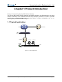
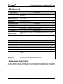
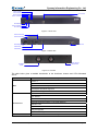
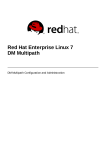
Synway SBO Series Gateway
SBO500 Gateway
Version 1.6.2
Synway Information Engineering Co., Ltd
www.synway.net
Synway Information Engineering Co., Ltd
Content
Content ..................................................................................................i
Copyright Declaration...........................................................................iii
Revision History....................................................................................iv
Chapter 1
1.1
1.2
1.3
1.4
Product Introduction ........................................................1
Typical Application ......................................................................................... 1
Feature List.................................................................................................... 2
Hardware Description .................................................................................... 2
Alarm Info ...................................................................................................... 4
Chapter 2
Quick Guide ......................................................................5
Chapter 3
WEB Configuration...........................................................7
3.1
3.2
System Login ................................................................................................. 7
Operation Info ................................................................................................ 8
3.2.1
3.2.2
3.2.3
3.3
SIP Settings ................................................................................................. 13
3.3.1
3.3.2
3.3.3
3.3.4
3.3.5
3.3.6
3.4
Whitelist ..................................................................................................................33
Blacklist ..................................................................................................................35
Number Pool...........................................................................................................36
Filtering Rule...........................................................................................................37
Number Manipulation................................................................................... 40
3.6.1
3.6.2
3.7
Routing Parameters ................................................................................................30
IP to IP ....................................................................................................................31
Number Filter ............................................................................................... 32
3.5.1
3.5.2
3.5.3
3.5.4
3.6
SIP Settings ............................................................................................................14
SIP Trunk ................................................................................................................17
SIP Register............................................................................................................20
SIP Account ............................................................................................................23
SIP Trunk Group .....................................................................................................25
Media Settings ........................................................................................................28
Route Settings ............................................................................................. 30
3.4.1
3.4.2
3.5
System Info...............................................................................................................8
IP Status .................................................................................................................10
Call Count ...............................................................................................................12
IP to IP CallerID ......................................................................................................40
IP to IP CalleeID .....................................................................................................42
System Tools ............................................................................................... 43
3.7.1
3.7.2
3.7.3
3.7.4
3.7.5
3.7.6
3.7.7
Network ..................................................................................................................44
Management...........................................................................................................45
IP Routing Table......................................................................................................46
SNMP Config ..........................................................................................................48
Configuration File....................................................................................................49
Signaling Capture ...................................................................................................50
Signaling Call Track ................................................................................................51
SMG SBO Series Gateway User Manual (Version 1.6.2)
Page i
Synway Information Engineering Co., Ltd
3.7.8
3.7.9
3.7.10
3.7.11
3.7.12
3.7.13
3.7.14
3.7.15
3.7.16
PING Test ...............................................................................................................52
TRACERT Test .......................................................................................................53
Modification Record ................................................................................................54
Backup & Upload ....................................................................................................55
Factory Reset .........................................................................................................55
Upgrade ..................................................................................................................56
Change Password ..................................................................................................56
Device Lock ............................................................................................................57
Restart ....................................................................................................................58
Chapter 4
Typical Applications .......................................................59
Appendix A Technical Specifications.................................................62
Appendix B Troubleshooting ..............................................................63
Appendix C Technical/sales Support .................................................64
SMG SBO Series Gateway User Manual (Version 1.6.2)
Page ii
Synway Information Engineering Co., Ltd
Copyright Declaration
All rights reserved; no part of this document may be reproduced or transmitted in any form or by
any means, electronic or mechanical, without prior written permission from Synway Information
Engineering Co., Ltd (hereinafter referred to as ‘Synway’).
Synway reserves all rights to modify this document without prior notice. Please contact Synway
for the latest version of this document before placing an order.
Synway has made every effort to ensure the accuracy of this document but does not guarantee
the absence of errors. Moreover, Synway assumes no responsibility in obtaining permission and
authorization of any third party patent, copyright or product involved in relation to the use of this
document.
SMG SBO Series Gateway User Manual (Version 1.6.2)
Page iii
Synway Information Engineering Co., Ltd
Revision History
Version
Date
Comments
Version 1.0.0
2015-05
Initial publication.
Version 1.6.2
2015-09
New revision
Note: Please visit our website http://www.synway.net to obtain the latest version of this document.
SMG SBO Series Gateway User Manual (Version 1.6.2)
Page iv
Synway Information Engineering Co., Ltd
Chapter 1 Product Introduction
Thank you for choosing Synway SBO Series Gateway!
The Synway SBO series gateway products (hereinafter referred to as ‘SBO gateway’) are mainly
used for connecting IP or enterprise PBX with the IP telephony network or IP PBX. It provides
such functions as transcoding, routing, number filtration, number manipulation and so on.
Currently, only SBO500 is available for you.
1.1 Typical Application
Internet
IMS Server
SBO
Gateway
IP PBX
IP Phone
IP Phone
Router
LAN
Figure 1-1 Typical Application
SMG SBO Series Gateway User Manual (Version 1.6.2)
Page 1
Synway Information Engineering Co., Ltd
1.2 Feature List
Basic Features
Description
IP Call
Call initiated from IP to a designated SIP trunk, via routing and number
manipulation.
Number Manipulation
Peels off some digits of a phone number from left/right, or adds a prefix/suffix to a
phone number.
VoIP Routing
Routing path: from IP to IP.
Signaling & Protocol
SIP Signaling
Description
Supported protocol: SIP V1.0/2.0, RFC3261
CODEC
DTMF Mode
Voice
G.711A, G.711U, G.729, G723, G722, AMR, iLBC
RFC2833, SIP INFO, INBAND
Network
Description
Network Protocol
Supported protocol: TCP/UDP, HTTP, ARP/RARP, DNS, NTP, TFTP, TELNET,
STUN
Static IP
IP address modification support
DNS
Domain Name Service support
Security
Admin Authentication
Description
Support admin authentication to guarantee the resource and data security
Maintain & Upgrade
Description
WEB Configuration
Support of configurations through the WEB user interface
Language
Chinese, English
Software Upgrade
Support of user interface, gateway service, kernel and firmware upgrades based
on WEB
Tracking Test
Support of Ping and Tracert tests based on WEB
SysLog Type
Three options available: ERROR, WARNING, INFO
1.3 Hardware Description
The SBO gateway features 1U rackmount design and integrates embedded LINUX system within
the POWERPC+DSP hardware architecture. It has 2 Kilomega-Ethernet ports (NET1 and NET2)
on the chassis. See the figures below for SBO500 appearance:
SMG SBO Series Gateway User Manual (Version 1.6.2)
Page 2
Synway Information Engineering Co., Ltd
LAN2 Indicator
LAN1 Indicator
Alarm Indicator
Power 1 Indicator
Console Port
Reset Button
Power 2 Indicator
Run Indicator
Figure 1-2 Front View
220V AC Power2
220V AC Power1
Network Port
Grounding Stud
Power1 Key
Power2 Key
Figure 1-3 Rear View
Screw Holes for
Foot Bracket
Ventilation
Holes
Figure 1-4 Left View
The table below gives a detailed introduction to the interfaces, buttons and LEDs illustrated
above:
Interface
Description
Amount: 2
Type: RJ-45
NET
Bandwidth: 10/100/1000Mbps
Self-Adaptive Bandwidth Supported
Auto MDI/MDIX Supported
Amount: 1
Type: RS-232
Baud Rate: 115200 bps
Console Port
Connector: RJ45 (See Figure 1-5 for signal definition)
Data Bits: 8 bits
Stop Bit: 1 bit
Parity Unsupported
Flow Control Unsupported
Button
SMG SBO Series Gateway User Manual (Version 1.6.2)
Description
Page 3
Synway Information Engineering Co., Ltd
Power Key
Reset Button
Power on/off the SBO gateway. You can turn on the two power keys at the same
time to have the power supply working in the hot-backup mode.
Restore the gateway to factory settings.
LED
Power Indicator
Description
Indicates the power state. It lights up when the gateway starts up with the power
cord well connected.
Run Indicator
Indicates the running status. For more details, refer to 1.4 Alarm Info.
Alarm Indicator
Alarms the device malfunction. For more details, refer to 1.4 Alarm Info.
Link Indicator
The green LED on the left of NET, indicating the network connection status.
ACT Indicator
The orange LED on the right of NET, whose flashing tells data are being
transmitted.
Note: The console port is used for debugging. While connection, the transmitting and receiving
lines of the gateway and the remote device should be cross-linked. That is, connect the
transmitting line of the gateway to the receiving line of the remote device, and vice verse. The
figure below illustrates the signal definition of the console port on the gateway.
Gateway RX
Gateway TX
GND
8
7
6
5
4
3
2
1
Figure 1-5 Console Port Signal Definition
For other hardware parameters, refer to Appendix A Technical Specifications.
1.4 Alarm Info
The SBO gateway is equipped with two indicators denoting the system’s running status: Run
Indicator (green) and Alarm Indicator (red). The table below explains the states and meanings of
the two indicators.
LED
Run Indicator
Alarm Indicator
State
Description
Go out
System is not yet started.
Light up
System is starting.
Flash
Device is running normally.
Go out
Device is working normally.
Light up
Flash
Upon startup: Device is running normally.
In runtime: Device goes abnormal.
System is abnormal.
Note:
z
The startup process consists of two stages: System Booting and Gateway Service
Startup. The system booting costs about 1 minute and once it succeeds, both the run
indicator and the alarm indicator light up. Then after the gateway service is successfully
started and the device begins to work normally, the run indicator flashes and the alarm
indicator goes out.
z
During runtime, if the alarm indicator lights up or flashes, it indicates that the device goes
abnormal. If you cannot figure out and solve the problem by yourself, please contact our
technicians for help. Go to Appendix C Technical/sales Support to find the contact way.
SMG SBO Series Gateway User Manual (Version 1.6.2)
Page 4
Synway Information Engineering Co., Ltd
Chapter 2 Quick Guide
This chapter is intended to help you grasp the basic operations of the SBO gateway in the
shortest time.
Step 1: Confirm that your packing box contains all the following things.
z
SBO Series Gateway *1
z
Angle Bracket *2, Rubber Foot Pad *4, Screw for Angle Bracket *8
z
220V Power Cord *2
z
Warranty Card *1
z
Installation Manual *1
Step 2: Properly fix the SBO gateway.
If you do not need to place the gateway on the rack, simply fix the 4 rubber foot pads. Otherwise,
you should first fix the 2 angle brackets onto the chassis and then place the chassis on the rack.
Step 3: Connect the power cord.
Make sure the device is well grounded before you connect the power cord. Check if the power
socket has the ground wire. If it doesn’t, use the grounding stud on the rear panel of the device
(See Figure 1-3) for earthing.
Note: Each SBO gateway has two power interfaces to meet the requirement for power supply hot
backup. As long as you properly connect and turn on these two power keys, either power supply
can guarantee the normal operation of the gateway even if the other fails.
Step 4: Connect the network cable.
Step 5: Log in the gateway.
Enter the original IP address (NET 1: 192.168.1.101 or NET 2: 192.168.0.101) of the SBO
gateway in the browser to go to the WEB interface. The original username and password of the
gateway are both ‘admin’. For detailed instructions about login, refer to 3.1 System Login. We
suggest you change the initial username and password via ‘System Tools Æ Change Password’
on the WEB interface as soon as possible after your first login. For detailed instructions about
changing the password, refer to 3.7.14 Change Password. After changing the password, you are
required to log in again.
Step 6: Modify IP address of the gateway.
You can modify the IP address of the gateway via ‘System Tools Æ Network’ on the WEB interface
to put it within your company’s NET. Refer to 3.7.1 Network for detailed instructions about IP
modification. After changing the IP address, you shall log in the gateway again using your new IP
address.
Step 7: Check the channel status.
You can check the status of the channels via ‘Operation Info Æ IP Status’. Refer to 3.2.2 IP Status
for detailed introductions.
Step 8: Set routing rules for calls.
Note: For your easy understanding and manipulation, all examples given in this step do not
involve registration.
Step 1: Configure the IP address of the remote SIP terminal which can establish conversations
with the gateway so that the calls from other terminals will be ignored. Refer to ‘SIP
Settings Æ SIP Trunk’ for detailed instructions. Click Add New to add a new SIP trunk,
SMG SBO Series Gateway User Manual (Version 1.6.2)
Page 5
Synway Information Engineering Co., Ltd
fill in ‘Remote IP’ and ‘Remote Port’ with the IP address and port of the remote SIP
terminal which will initiate calls to the gateway. You may use the default values for the
other configuration items.
Example: Provided the incoming IP address of the SIP trunk is 192.168.0.111 and the
port is 5060. Add SIP Trunk 0; set Remote IP to 192.168.0.111 and Remote Port to
5060. The outgoing IP address of the SIP trunk is 192.168.0.222 and the port is 5060.
Add SIP Trunk 1; set Remote IP to 192.168.0.222 and Remote Port to 5060.
Step 2: Add the IP address of the SIP trunks configured in Step 1 into the corresponding SIP
trunk group. Refer to SIP Settings Æ SIP Trunk Group’ for detailed instructions. Click
Add New to add the SIP trunk group. Select the SIP trunk configured in Step 1 as ‘SIP
Trunks’. You may use the default values for the other configuration items.
Example: Add SIP Trunk Group 0. Check the checkbox before 0 for SIP Trunks and
keep the default values for the other configuration items. Add SIP Trunk Group 1. Check
the checkbox before 1 for SIP Trunks and keep the default values for the other
configuration items.
Step 3: Add routing rules. Refer to ‘Route Settings Æ IPÆIP’ for detailed instructions. Select the
SIP trunk group 0 set in Step 2 as ‘Call Initiator’ and the SIP trunk group 1 set in Step 2
as ‘Call Destination’. You may use the default values for the other configuration items.
Example: Select SIP Trunk Group[0] as Call Initiator and SIP Trunk Group[1] as Call
Destination. Keep the default values for the other configuration items.
Step 4: Initiate a call from the SIP trunk 0 configured in Step 1 to the IP address and port of the
SBO gateway. Thus you can establish a call conversation via SIP trunk[1] with the IP
terminal. (Note: The format used for calling an IP address via SIP trunk is as follows:
username@IP address.)
Example: Provided the IP address of the SBO gateway is 192.168.0.101 and the port is
5060. Provided 123 is a number which conforms to the number receiving rule of the
remote device. Initiate a call from SIP trunk 0 to the IP address 192.168.0.101 (in the
format: [email protected]) and you can establish a call conversation via SIP trunk[1]
to the number 123.
Special Instructions:
z
The chassis of the SBO gateway must be grounded for safety reasons, according to
standard industry requirements. A simple way is earthing with the third pin on the plug or
the grounding studs on the machine. No or improper grounding may cause instability in
operation as well as decrease in lightning resistance.
z
As the device will gradually heat up while being used, please maintain good ventilation to
prevent sudden failure, ensuring that the ventilation holes (see Figure 1-4) are never
jammed.
z
During runtime, if the alarm indicator lights up or flashes, it indicates that the device goes
abnormal. If you cannot figure out and solve the problem by yourself, please contact our
technicians for help. Otherwise it may lead to a drop in performance or unexpected
errors.
SMG SBO Series Gateway User Manual (Version 1.6.2)
Page 6
Synway Information Engineering Co., Ltd
Chapter 3 WEB Configuration
3.1 System Login
Type the IP address into the browser and enter the login interface. See Figure 3-1.
Figure 3-1 Login Interface
The gateway only serves one user, whose original username and password are both ‘admin’. You
can change the username and the password via ‘System Tools Æ Change Password’ on the WEB
interface. For detailed instructions, refer to 3.7.14 Change Password.
After login, you can see the main interface as below.
Figure 3-2 Main Interface
SMG SBO Series Gateway User Manual (Version 1.6.2)
Page 7
Synway Information Engineering Co., Ltd
3.2 Operation Info
Operation Info includes three parts: System Info, IP Status and Call Count, showing the current
running status of the gateway. See Figure 3-3.
Figure 3-3 Operation Info
3.2.1 System Info
Figure 3-4 System Info Interface
See Figure 3-4 for the system info interface. You can click Refresh to obtain the latest system
information. The table below explains the items shown in Figure 3-4.
Item
SMG SBO Series Gateway User Manual (Version 1.6.2)
Description
Page 8
Synway Information Engineering Co., Ltd
MAC Address
IP Address
MAC address of NET 1 or NET 2.
The three parameters from left to right are IP address, subnet mask and default
gateway of NET 1 or NET 2.
DNS Server
DNS server address of NET 1 or NET 2.
Receive Packets,
The amount of receive/transmit packets after the gateway’s startup, including three
Transmit Packets
categories: All, Error and Drop.
Current Speed
The current speed of data receiving and transmitting.
The work mode of the network, including five options: 10 Mbps Half Duplex, 10
Work Mode
Mbps Full Duplex, 100 Mbps Half Duplex, 100 Mbps Full Duplex and 1000 Mbps
Full Duplex.
Runtime
Time of the gateway keeping running normally after startup. This parameter
updates every 2s.
Serial Number
Unique serial number of a SBO gateway.
WEB
Current version of the WEB interface.
Gateway
Current version of the gateway service.
Uboot
Current version of Uboot.
Kernel
Current version of the system kernel on the gateway.
Firmware
Current version of the firmware on the gateway.
SMG SBO Series Gateway User Manual (Version 1.6.2)
Page 9
Synway Information Engineering Co., Ltd
3.2.2 IP Status
Figure 3-5 IP Status Interface
See Figure 3-5 for the IP status interface which shows the real-time status of each IP channel on
the gateway.
Item
Channel No.
Description
The corresponding serial number of IP on the device.
z
Displays the channel state in real time. You can move the mouse onto the
channel state icon for detailed information about the channel and the call, such
State
as: call direction, calling party number and called party number. The channel
states include:
State
Icon
SMG SBO Series Gateway User Manual (Version 1.6.2)
Description
Page 10
Synway Information Engineering Co., Ltd
Idle
Wait Answer
The channel is available.
The channel receives the ringback tone and is waiting
for the called party to pick up the phone.
Ringing
The channel is in the ringing state.
Talking
The channel is in a conversation.
Pending
The channel is in the pending state
Dialing
The channel is dialing.
Wait Message
The channel is waiting for the message from remote
PBX.
Note: The gateway provides the fuzzy search feature on this interface. After you click any
characters on Figure 3-5 and press the ‘F’ button, the search box will emerge on the right top of
this page. Then you can input the key characters and the gateway will locate the channel on
which there is an ongoing call that conforms to the fuzzy search condition.
Take an example: As shown in Figure 3-6, after we input the character 114 to the search box, and
click the Search button, the gateway does a fuzzy search and locates that the ongoing call whose
CalledID contains the character 114 occurs on Channel 4 of Channel Group 1.
SMG SBO Series Gateway User Manual (Version 1.6.2)
Page 11
Synway Information Engineering Co., Ltd
Figure 3-6 Search Calls
3.2.3 Call Count
Figure 3-7 Call Count Interface
See Figure 3-7 for the call count Interface. The above list shows the detailed information about all
the calls counted from the startup of the gateway service to the latest open or refresh of this
SMG SBO Series Gateway User Manual (Version 1.6.2)
Page 12
Synway Information Engineering Co., Ltd
interface. You can click Refresh to obtain the latest call count information, click Download to
download the call count logs. The table below explains the items shown in Figure 3-7.
Item
Description
Release Cause
Reason to release the call.
Normal call clearing
Total number of the calls which are normally cleared.
Cancelled by calling
party
User busy
Total number of the calls which are cancelled by the calling party.
Total number of the calls which fail as the called party has been occupied and
replies a busy message.
No answer from
Total number of the calls which fail as the called party does not pick up the call in a
user
long time or the calling party hangs up the call before the called party picks it up.
Routing failed
Total number of the calls which fail because no routing rules are matched.
Resource
unavailable
Call failed
Total number of the calls which fail because no voice channel is available.
Total number of the calls which fail as the called party number does not conform to
the number-receiving rule or for relative reasons.
Others
Total number of the calls which fail because of other reasons.
Number
Total number of the calls on each state.
Percentage
The percentage of the calls with a release cause to total calls.
3.3 SIP Settings
SIP Settings includes six parts: SIP, SIP Trunk, SIP Register, SIP Account, SIP Trunk Group
and Media. See Figure 3-8. SIP is used to configure the general SIP parameters; SIP Trunk is
used to set the basic and register information of the SIP trunk; SIP Register is used for the
registration of SIP; SIP Account is used for registering SIP accounts to the SIP server; SIP Trunk
Group is to manage SIP trunks by group; and Media is to set the RTP port and the payload type.
Figure 3-8 SIP Settings
SMG SBO Series Gateway User Manual (Version 1.6.2)
Page 13
Synway Information Engineering Co., Ltd
3.3.1 SIP Settings
SMG SBO Series Gateway User Manual (Version 1.6.2)
Page 14
Synway Information Engineering Co., Ltd
SMG SBO Series Gateway User Manual (Version 1.6.2)
Page 15
Synway Information Engineering Co., Ltd
Figure 3-9 SIP Settings Interface
See Figure 3-9 for the SIP settings interface where you can configure the general SIP parameters.
After configuration, click Save to save your settings into the gateway or click Reset to restore the
configurations. If a dialog box pops up after you save your settings asking you to restart the
service, do it immediately to apply the changes. Refer to 3.7.16 Restart for detailed instructions.
The table below explains the items shown in Figure 3-9.
Item
Description
SIP Address of WAN
IP address of SIP signaling for WAN, using NET 1 by default.
Auto Change
The SIP address of WAN will automatically shift to another LAN if the default one is
Default Gateway
unavailable. By default, the feature is disabled.
SIP Signaling Port
Monitoring port of SIP signaling. Range of value: 5001~65535, with the default
value of 5060.
There are two optional ways to obtain the calling party number: from Username of
Obtain CallerID from
“From” Field or from Displayname of “From” Field. The default value is from
Username of “From” Field.
Obtain CalleeID
There are two optional ways to obtain the called party number: from “To” Field or
from
from “Request” Field. The default value is from “Request” Field.
NAT Traversal,
Sets whether to enable the NAT traversal. By default this feature is disabled. There
Traversal Type
is only one traversal type: Port Mapping.
LAN1 Mapping
Address, LAN2
Mapping Address
The mapping addresses of LAN1 and LAN2 in case the NAT traversal is enabled. If
the port mapping is selected as the traversal type, you are required to set the
mapping address and port on the router and fill in the corresponding information
here as well.
SIP Transport
There are two modes UDP and TCP available for running the SIP protocol. The
Protocol
default value is UDP.
SIP Encryption
Once this feature is enabled, you can encrypt the SIP signal following selecting an
encryption criterion and setting a key. By default it is disabled.
Encryption Criterion
The criterion used to encrypt the SIP signal. At present only VOS1.1 is supported.
Key
The key to encrypt the SIP signal.
RTP Encryption
Once this feature is enabled, you can encrypt the RTP package. By default it is
disabled.
When this feature is enabled, the RTP reception address or port carried by the
RTP Self-adaption
signaling message from the remote end, if not consistent with the actual state, will
be updated to the actual RTP reception address or port. By default, this feature is
disabled.
UDP Header
When this feature is enabled, the gateway will automatically calculate the check
Checksum
sum of the UDP header during RTP transmission.
Rport
DSCP
Voice Media
When this feature is enabled, a corresponding Rport field will be added to the Via
message of SIP. By default, it is disabled.
Sets whether to enable the DSCP differentiated services code point. By default, it is
disabled.
Sets the priority of the voice media for DSCP. The voice media with a bigger value
has a higher priority. The value range is 0~63, with the default value of 46.
SMG SBO Series Gateway User Manual (Version 1.6.2)
Page 16
Synway Information Engineering Co., Ltd
Signal Control
Sets the priority of the signal control for DSCP. The signal control with a bigger
value has a higher priority. The value range is 0~63, with the default value of 26.
Calls from SIP Trunk
Once this feature is enabled, the gateway will only accept the calls from the IP
Address only
addresses set in SIP Settings Æ SIP Trunk. By default, it is disabled.
Switch Signal Port if
SIP Registration
Failed
Working Period,
Period
If the SIP registration fails, the SIP signaling port N will switch to N+1 for a new
registration. It will continue until the registration succeeds.
The work period for the gateway. You can specify a certain period for the gateway to
make calls. By default, the gateway is allowed to make calls any time in the day (24
Hours).
Sets the maximum time for the SIP channel to wait for the answer from the called
Maximum Wait
party of the outgoing call it initiates. If the call is not answered within the specified
Answer Time
time period, it will be canceled by the channel automatically. The default value is 60,
calculated by s.
Sets the maximum time for the SIP channel to wait for the RTP packet. If no RTP
Maximum Wait RTP
packet is received within the specified time period, the channel will enter the
Time
pending state automatically and release the call. The default value is 0, calculated
by s.
3.3.2 SIP Trunk
By default, there is no available SIP trunk information. Click Add New to add a new SIP trunk.
See Figure 3-10 for the SIP trunk adding interface.
SMG SBO Series Gateway User Manual (Version 1.6.2)
Page 17
Synway Information Engineering Co., Ltd
Figure 3-10 Add New SIP Trunk
The table below explains the items shown in Figure 3-10.
Item
Index
Remote Address
Description
The unique index of each SIP trunk.
Address of the SIP trunk, i.e. the IP address or domain name of the remote SIP
terminal which will establish call conversation with the gateway.
Remote Port
Port of the SIP trunk.
Wan Option
Select the network port which used for WAN. The default setting is NET 1.
Transport Protocol
Max. Voice
Channels
SIP transport protocol, providing two modes UDP and TCP. The default value is
UDP.
Maximum number of voice channels allocated by the SIP trunk to the gateway.
Outgoing Voice
Maximum number of voice channels for the outgoing calls allocated by the SIP
Resource
trunk to the gateway.
SMG SBO Series Gateway User Manual (Version 1.6.2)
Page 18
Synway Information Engineering Co., Ltd
Incoming Voice
Maximum number of voice channels for the incoming calls allocated by the SIP
Resource
trunk to the gateway.
Working Period,
Period
The work period for the gateway, You can specify a certain period for the gateway to
make calls. By default, the gateway is allowed to make calls any time in the day (24
Hours).
Supported CODECs and their corresponding priorities for the SIP trunk to establish
a call conversation. The table below explains the sub-items:
Sub-item
Description
Priority for choosing the CODEC in an SIP conversation. The
Priority
smaller the value is, the higher the priority will be.
CODEC Priority
CODEC
Seven optional CODECs are supported: G711A, G711U, G729,
G722, G723, AMR and iLBC.
See 3.3.6 Media Settings for the detailed parameters for each CODEC.
The default CODEC for the SIP trunk is the same as that set in 3.3.6 Media
Settings.
After configuration, click Save to save the settings into the gateway or click Close to cancel the
settings. See Figure 3-11 for the SIP Trunk Settings Interface
Figure 3-11 SIP Trunk Settings Interface
Click Modify in Figure 3-11 to modify a SIP trunk. See Figure 3-12 for the SIP trunk modification
interface. The configuration items on this interface are the same as those on the Add New SIP
Trunk interface.
SMG SBO Series Gateway User Manual (Version 1.6.2)
Page 19
Synway Information Engineering Co., Ltd
Figure 3-12 Modify SIP Trunk
To delete a SIP trunk, check the checkbox before the corresponding index in Figure 3-11 and click
the Delete button. Check All means to select all available items on the current page; Uncheck
All means to cancel all selections on the current page; Inverse means to uncheck the selected
items and check the unselected. To clear all SIP trunks at a time, click the Clear All button in
Figure 3-11.
3.3.3 SIP Register
By default, there is no SIP register available on the gateway. Click Add New to add them manually.
See Figure 3-13.
SMG SBO Series Gateway User Manual (Version 1.6.2)
Page 20
Synway Information Engineering Co., Ltd
Figure 3-13 Add SIP Register Interface
The table below explains the items shown in the above figure.
Item
Description
Index
The unique index of each SIP register.
SIP Trunk No.
The number of the SIP trunk which registers to the SIP server.
When the gateway initiates a call to SIP, this item corresponds to the username of
Username
SIP; when the gateway initiates a call to IP, this item corresponds to the displayed
CallerID.
Password
Registration password of the gateway. To register the gateway to the SIP server,
both configuration items Username and Password should be filled in.
Register Address
Address of the SIP server to which the SIP trunk is registered.
Register Port
The signaling port of the SIP trunk.
Domain Name
Domain name of the gateway used for SIP registry.
SMG SBO Series Gateway User Manual (Version 1.6.2)
Page 21
Synway Information Engineering Co., Ltd
Validity period of the SIP registry. Once the registry is overdue, the gateway should
Register Expires
be registered again. Range of value: 10~3600, calculated by s, with the default
value of 3600.
Once this feature is enabled, the gateway will send signaling messages to the
corresponding externally bound address and port when it registers to the server.
IMS Network
Only when this feature is enabled will these items Externally Bound Address,
Externally Bound Port and Authentication Username be shown.
Externally
Bound
Address
Externally
Bound
Port
Authentication
Username
Externally bound IP address for registration.
Externally bound port for registration.
Authentication username for registration.
After configuration, click Save to save the settings into the gateway or click Close to cancel the
settings. See Figure 3-14 for the SIP Register Information List.
Figure 3-14 SIP Register Information List
Click Modify in Figure 3-14 to modify a SIP register. The configuration items on the SIP Register
Modification Interface are the same as those on the Add New SIP Register interface.
SMG SBO Series Gateway User Manual (Version 1.6.2)
Page 22
Synway Information Engineering Co., Ltd
Figure 3-15 SIP Register Modification Interface
To delete a SIP register, check the checkbox before the corresponding index in Figure 3-14 and
click the Delete button. Check All means to select all available items on the current page;
Uncheck All means to cancel all selections on the current page; Inverse means to uncheck the
selected items and check the unselected. To clear all SIP registers at a time, click the Clear All
button in Figure 3-14.
3.3.4 SIP Account
By default, there is no SIP account available on the gateway. Click Add New to add them
manually. See Figure 3-16.
SMG SBO Series Gateway User Manual (Version 1.6.2)
Page 23
Synway Information Engineering Co., Ltd
Figure 3-16 Add New SIP Account
The table below explains the items shown in above figures.
Item
Description
Index
The unique index of each SIP account.
SIP Trunk No.
The number of the SIP trunk to which the SIP account is registered.
Username
Password
The registration username of the SIP account. Once the SIP account is successfully
registered, the SIP server can initiate calls to the gateway via Username.
The registration password of the SIP account. To register the SIP account to the SIP
trunk, both configuration items Username and Password should be filled in.
The validity period of the SIP account registry. Once the registry is overdue, the SIP
Register Expires
account should be registered again. Range of value: 10~3600, calculated by s, with
the default value of 3600.
Register Status
The registration status of the SIP account. It is either Registered or Failed.
Authentication username of a port, used to register the port to the SIP server when
Authentication
IMS network is enabled.
Username
Note: This item appears only when IMS Network is enabled on the SIP trunk
corresponding to this SIP account.
Description
More information about each SIP account.
After configuration, click Save to save the settings into the gateway or click Close to cancel the
settings. See Figure 3-17 for the SIP Account Settings Interface
SMG SBO Series Gateway User Manual (Version 1.6.2)
Page 24
Synway Information Engineering Co., Ltd
Figure 3-17 SIP Account Settings Interface
Click Modify in Figure 3-17 to modify a SIP account. See Figure 3-18 for the SIP account
modification interface. The configuration items on this interface are the same as those on the Add
New SIP Account interface.
Figure 3-18 Modify SIP Account
To delete a SIP account, check the checkbox before the corresponding index in Figure 3-17 and
click the Delete button. Check All means to select all available items on the current page;
Uncheck All means to cancel all selections on the current page; Inverse means to uncheck the
selected items and check the unselected. To clear all SIP accounts at a time, click the Clear All
button in Figure 3-17.
3.3.5 SIP Trunk Group
By default, there is no SIP trunk group available on the gateway. Click Add New to add them
manually. See Figure 3-19.
SMG SBO Series Gateway User Manual (Version 1.6.2)
Page 25
Synway Information Engineering Co., Ltd
Figure 3-19 Add New SIP Trunk Group
The table below explains the items shown in Figure 3-19.
Item
Index
Description
Description
The unique index of each SIP trunk group, which is mainly used in the configuration
of routing rules and number manipulation rules to correspond to SIP trunk groups.
More information about each SIP trunk group.
When the SIP trunk group receives a call, it will choose a SIP trunk based on the
select mode set by this configuration item to ring. The optional values and their
corresponding meanings are described in the table below.
Option
Increase
SIP Trunk Select
Mode
Decrease
Description
Search for an idle SIP trunk in the ascending order of the
SIP trunk number, starting from the minimum.
Search for an idle SIP trunk in the descending order of
the SIP trunk number, starting from the maximum.
Provided SIP Trunk N is the available SIP trunk found last
Cyclic Increase
time. Search for an idle SIP trunk in the ascending order
of the SIP trunk number, starting from SIP Trunk N+1.
Provided SIP Trunk N is the available SIP trunk found last
Cyclic Decrease
time. Search for an idle SIP trunk in the descending order
of the SIP trunk number, starting from SIP Trunk N-1.
The SIP trunks in the SIP trunk group. If the checkbox before a SIP trunk is grey, it
SIP Trunks
indicates that the SIP trunk has been occupied. The ticked SIP trunks herein will be
displayed in the column ‘SIP Trunks’ in Figure 3-20.
After configuration, click Save to save the settings into the gateway or click Cancel to cancel the
settings. See Figure 3-20 for the SIP Trunk Group Setting Interface.
SMG SBO Series Gateway User Manual (Version 1.6.2)
Page 26
Synway Information Engineering Co., Ltd
Figure 3-20 SIP Trunk Group Settings Interface
Click Modify in Figure 3-20 to modify a SIP trunk group. See Figure 3-21 for the SIP trunk group
modification interface. The configuration items on this interface are the same as those on the Add
New SIP Trunk Group interface.
Figure 3-21 Modify SIP Trunk Group
To delete a SIP trunk group, check the checkbox before the corresponding index in Figure 3-20
and click the Delete button. Check All means to select all available items on the current page;
Uncheck All means to cancel all selections on the current page; Inverse means to uncheck the
selected items and check the unselected. To clear all SIP trunk groups at a time, click the Clear
All button in Figure 3-20.
SMG SBO Series Gateway User Manual (Version 1.6.2)
Page 27
Synway Information Engineering Co., Ltd
3.3.6 Media Settings
Figure 3-22 Media Settings Interface
See Figure 3-22 for the media settings interface where you can configure the RTP port and
payload type depending on your requirements. After configuration, click Save to save your
settings into the gateway or click Reset to restore the configurations. If a dialog box pops up after
you save your settings asking you to restart the service, do it immediately to apply the changes.
Refer to 3.7.16 Restart for detailed instructions. The table below explains the items shown in
Figure 3-22.
Item
Description
DTMF Transmit
Sets the mode for the IP channel to send DTMF signals. The optional values are
Mode
RFC2833, In-band and Signaling, with the default value of RFC2833.
RFC2833 Payload
Payload of the RFC2833 formatted DTMF signals on the IP channel. Range of
value: 90~127, with the default value of 101.
SMG SBO Series Gateway User Manual (Version 1.6.2)
Page 28
Synway Information Engineering Co., Ltd
Supported RTP port range for the IP end to establish a call conversation, with the
RTP Port Range
lower limit of 6000 and the upper limit of 60000 and the difference between larger
than 2048. The default value is 6000-10000.
Sets whether to send comfort noise packets to replace RTP packets or never to
send RTP packets to reduce the bandwidth usage when there is no voice signal
Silence
throughout an IP conversation. The optional values are Enable and Disable, with
Suppression
the default value of Disable.
Note: When G723 is selected as CODEC, this configuration setting will turn to
Enable automatically.
Noise Reduction
JitterMode
Once this feature is enabled, the volume of the noise accompanied with the line will
be reduced automatically. The default setting is Enable.
Sets the working mode of JitterBuffer. The optional values are Static Mode and
Adaptive Mode, with the default value of Static Mode.
Acceptable jitter for data packets transmission over IP, which indicates the buffering
capacity. A larger JitterBuffer means a higher jitter processing capability but as well
JitterBuffer
as an increased voice delay, while a smaller JitterBuffer means a lower jitter
processing capability but as well as a decreased voice delay. Range of value:
0~280, calculated by ms, with the default value of 100.
Sets the initial delay applied to received packets upon accepting packets later than
JitterUnderrunLead
the expected value set in JitterBuffer Item. Range of value: 0~280, calculated by
ms, with the default value of 100,
Note: Only when JitterMode is set to Static Mode will this item be shown.
Sets the beforehand time inserted if receiving packets is ahead of time (the time of
JitterOverrunLead
receiving is earlier than 300 minus the value set in JitterBuffer). Rnage of value:
0~280, calculated by ms, with the default value of 50,
Note: Only when JitterMode is set to Static Mode will this item be shown.
Sets the minimum delay that can be set by the adaptive jitter function. It must be
JitterMin
smaller than the value set in JitterBuffer. Range of value: 0~280, calculated by ms,
with the default value of 80.
Note: Only when JitterMode is set to Adaptive Mode will this item be shown.
Sets the rate of delay reduction under the adaptive mode. It defines the maximum
JitterDecreaseRatio
percentage of the silence that can be removed in delay reduction. Range of value:
0~100, with the default value of 50,
Note: Only when JitterMode is set to Adaptive Mode will this item be shown.
Sets the maximum delay increased during a silence period. Range of value: 0~280,
JitterIncreaseMax
calculated by ms, with the default value of 30,
Note: Only when JitterMode is set to Adaptive Mode will this item be shown.
Voice Gain Output
Adjusts the voice gain of call from IP to IP. The value must be a multiple of 3. Range
from IP
of value: -24~24, calculated by dB, with the default value of 0.
Sets CODECs for the IP end to establish a call conversation. The table below
CODEC Setting
explains the sub-items:
Sub-item
SMG SBO Series Gateway User Manual (Version 1.6.2)
Description
Page 29
Synway Information Engineering Co., Ltd
Priority
CODEC
Packing Time
Bit Rate
Priority for choosing the CODEC in an SIP conversation. The
smaller the value is, the higher the priority will be.
Seven optional CODECs are supported: G711A, G711U, G729,
G723, G722, AMR and iLBC.
Time interval for packing an RTP packet, calculated by ms.
The number of thousand bits (excluding the packet header) that
are conveyed per second.
By default, all of the seven CODECs are supported and ordered G711A, G711U,
G729, G723, G722, AMR and iLBC by priority from high to low. The CODECs set
here will be the default CODEC for the new added SIP trunks.
The packing time and bit rate supported by different CODECs are listed in the table
below. Those values in bold face are the default values.
COEDC
Packing Time (ms)
Bit Rate (kbps)
G711A
5 / 10 / 20 / 30 / 40 / 50 / 60
64
G711U
5 / 10 / 20 / 30 / 40 / 50 / 60
64
G729
20
8
G723
30 / 60 / 90
5.3 / 6.3
G722
5 / 10 / 20 / 30 / 40
64
AMR
20 / 40 / 60 / 80 / 100
iLBC
20 / 30 / 40 / 60
4.75 / 5.15 / 5.90 / 6.70 / 7.40 /
7.95 / 10.20 / 12.20
15.2
3.4 Route Settings
Route Settings is used to specify the routing rules for calls from IPÆIP. See Figure 3-23.
Figure 3-23 Route Settings
3.4.1 Routing Parameters
Figure 3-24 Routing Parameters Configuration Interface
See Figure 3-24 for the routing parameters configuration interface. On this interface, you can set
the routing rules for calls from IPÆIP to be routing before or after number manipulation. The
default value is Route before Number Manipulate.
SMG SBO Series Gateway User Manual (Version 1.6.2)
Page 30
Synway Information Engineering Co., Ltd
After configuration, click Save to save the above settings into the gateway.
3.4.2 IP to IP
By default, there is no IPÆIP routing rule available on the gateway. Click Add New to add them
manually. See Figure 3-25 for the IPÆIP routing rule adding interface.
Figure 3-25 Add New Routing Rule (IPÆIP)
The table below explains the items shown in the above figure.
Item
Description
The unique index of each routing rule, which denotes its priority. A routing rule with
Index
a smaller index value has a higher priority. If a call matches several routing rules, it
will be processed according to the one with the highest priority.
Call Initiator
SIP trunk group from where the call is initiated. This item can be set to a specific
SIP trunk group or SIP Trunk Group [ANY] which indicates any SIP trunk group.
A string of numbers at the beginning of the calling/called party number. This item
can be set to a specific string or “*” which indicates any string. These two
CallerID Prefix,
configuration items together with Call Initiator can specify the calls which apply to a
CalleeID Prefix
routing rule.
Note: Multiple rules are supported for CallerID/CalleeID prefix. They are separated
by “:”.
Call Destination
Number Filter
Description
SIP trunk group to which the call will be routed.
Number filter rule which will be applicable to this route. It is set in Number Filter.
See 3.5.4 Filtering Rule for details.
More information about each routing rule.
SMG SBO Series Gateway User Manual (Version 1.6.2)
Page 31
Synway Information Engineering Co., Ltd
After configuration, click Save to save the settings into the gateway or click Close to cancel the
settings. See Figure 3-26 for the IPÆIP Routing Rule Configuration Interface.
Figure 3-26 IPÆIP Routing Rule Configuration Interface
Click Modify in Figure 3-26 to modify a routing rule. See Figure 3-27 for the IPÆIP routing rule
modification interface. The configuration items on this interface are the same as those on the Add
New Routing Rule (IPÆIP) interface. Note that the item Index cannot be modified.
Figure 3-27 Modify Routing Rule (IPÆIP)
To delete a routing rule, check the checkbox before the corresponding index in Figure 3-26 and
click the Delete button. Check All means to select all available items on the current page;
Uncheck All means to cancel all selections on the current page; Inverse means to uncheck the
selected items and check the unselected. To clear all routing rules at a time, click the Clear All
button in Figure 3-26.
3.5 Number Filter
Number Filter includes four parts: Whitelist, Blacklist, Number Pool and Filtering Rule. See
Figure 3-28.
SMG SBO Series Gateway User Manual (Version 1.6.2)
Page 32
Synway Information Engineering Co., Ltd
Figure 3-28 Number Filter Interface
3.5.1 Whitelist
Figure 3-29 Whitelist Setting Interface
See Figure 3-29 for the Whitelist Setting Interface, which includes two parts: CallerID Whitelist
and CalleeID Whitelist.
A new CallerID/CalleeID whitelist can be added by the Add New button. See Figure 3-30, Figure
3-31 for CallerID/CalleeID whitelist adding interface.
Figure 3-30 Add New CallerIDs in Whitelist Interface
SMG SBO Series Gateway User Manual (Version 1.6.2)
Page 33
Synway Information Engineering Co., Ltd
Figure 3-31 Add New CalleeIDs in Whitelist Interface
The table below explains the items shown in above figures.
Item
Group
No. in Group
Description
The corresponding Group ID for CallerIDs/CalleeIDs in the whitelist. The value
range is 0~7.
The corresponding No. for different CallerIDs/CalleeIDs in a same group.
CallerID in the whitelist, which must be filled in with numbers or “*” (indicating any
CallerID
string) and can not be left empty. Example: 135*1 denotes any CallerIDs which start
from 135 and end with 1 will be accepted.
CalleeID in the whitelist, which must be filled in with numbers or “*” (indicating any
CalleeID
string) and can not be left empty. Example: 135*1 denotes any CalleeIDs which start
from 135 and end with 1 will be accepted.
After configuration, click Save to save the above settings into the gateway or click Close to cancel
the settings.
Click Modify in Figure 3-29 to modify the CallerID or CalleeID whitelist. See Figure 3-32, Figure
3-33 for CallerIDs/CalleeIDs on the Whitelist Modification interface. The configuration items on
this interface are the same as those on the Add New CallerIDs/CalleeIDs in Whitelist interface.
The item Group No. cannot be modified.
Figure 3-32 Modify CallerIDs in Whitelist
SMG SBO Series Gateway User Manual (Version 1.6.2)
Page 34
Synway Information Engineering Co., Ltd
Figure 3-33 Modify CalleeIDs in Whitelist
To delete a CallerIDs/CalleeIDs in the whitelist, check the checkbox before the corresponding
index in Figure 3-29 and click the ‘Delete’ button. To clear all CallerIDs/CalleeIDs in the whitelist
at a time, click the Clear All button in Figure 3-29.
Note: If a CallerID or CalleeID set in the whitelist is the same as one in the blacklist, it will go
invalid. That is, the blacklist has a higher priority than the whitelist. The total amount of numbers in
both whitelist and blacklist cannot exceed 5000.
3.5.2 Blacklist
Figure 3-34 Blacklist Setting Interface
The Blacklist Setting interface is almost the same as the Whitelist Setting interface; only the
whitelist changes to the blacklist. See Figure 3-34. The configuration items on this interface are
the same as those on the Whitelist Setting interface (Figure 3-30, Figure 3-31).
Note: The lacklist has a higher priority than the whitelist. That is, if the same number exists in both
blacklist and whitelist, the number in blacklist has priority.
SMG SBO Series Gateway User Manual (Version 1.6.2)
Page 35
Synway Information Engineering Co., Ltd
3.5.3 Number Pool
Figure 3-35 Number Pool Setting Interface
See Figure 3-35 for the Number Pool Setting interface. A new number pool can be added by the
Add New button on the bottom right corner of the list in the above figure. See Figure 3-36 for the
Number Pool adding interface.
Figure 3-36 Add New Number Pool
The table below explains the items shown in the above figure.
Item
Group
No. in Group
Starting Number
Number Amount
Description
The corresponding Group ID for numbers in the number pool. The value range is
0~15.
The corresponding No. for different numbers in a same group. It supports up to 100
number s in one group.
The starting number in a number Pool. It must be filled in with numbers and can not
be left empty.
The amount of the numbers in the number pool. The value range is 1~999999999.
After configuration, click Save to save the above settings into the gateway or click Close to cancel
the settings.
SMG SBO Series Gateway User Manual (Version 1.6.2)
Page 36
Synway Information Engineering Co., Ltd
Click Modify in Figure 3-35 to modify the number pool. See Figure 3-37 for the number pool
modification interface. The configuration items on this interface are the same as those on the Add
New Number Pool interface.
Figure 3-37 Modify Number Pool Interface
To delete a number pool, check the checkbox before the corresponding index in Figure 3-35 and
click the ‘Delete’ button. To clear all number pools at a time, click the Clear All button in Figure
3-35.
3.5.4 Filtering Rule
Figure 3-38 Filtering Rule Setting Interface
See Figure 3-38 for the Filtering Rule Setting Interface. A new filtering rule can be added by the
Add New button on the bottom right corner of the list in the above figure. See Figure 3-39 for the
Filtering Rule Adding interface.
SMG SBO Series Gateway User Manual (Version 1.6.2)
Page 37
Synway Information Engineering Co., Ltd
Figure 3-39 Add New Filtering Rule
The table below explains the items shown in the above figure.
Item
Description
No.
The corresponding number for a filtering rule. The value range is 0~99.
CallerID Whitelist
The Group No. of CallerIDs saved on the whitelist setting interface.
CalleeID Whitelist
The Group No. of CalleeIDs saved on the whitelist setting interface.
CallerID Blacklist
The Group No. of CallerIDs saved on the blacklist setting interface.
CalleeID Blacklist
The Group No. of CalleeIDs saved on the blacklist setting interface.
CallerID Pool in
Select a Group No. which is set in the whitelist from the number pool as the CallerID
Whitelist
pool in whitelist.
CallerID Pool in
Select a Group No. which is set in the blacklist from the number pool as the CallerID
Blacklist
pool in blacklist.
CalleeID Pool in
Select a Group No. which is set in the whitelist from the number pool as the CalleeID
Whitelist
pool in whitelist.
SMG SBO Series Gateway User Manual (Version 1.6.2)
Page 38
Synway Information Engineering Co., Ltd
CalleeID Pool in
Select a Group No. which is set in the blacklist from the number pool as the CalleeID
Blacklist
pool in blacklist.
Original CalleeID
Select a Group No. which is set in the whitelist from the number pool as the original
Pool in Whitelist
CalleeID pool in whitelist.
Original CalleeID
Select a Group No. which is set in the blacklist from the number pool as the original
Pool in Blacklist
CalleeID pool in blacklist.
Description
Remarks for the filtering rule. It can be any information, but can not be left empty.
After configuration, click Save to save the above settings into the gateway or click Close to cancel
the settings.
Click Modify in Figure 3-38 to modify the filtering rule. See Figure 3-40 for the filtering rule
modification interface. The configuration items on this interface are the same as those on the Add
New Filtering Rule interface.
Figure 3-40 Modify Filtering Rule Interface
To delete a filtering rule, check the checkbox before the corresponding index in Figure 3-38 and
SMG SBO Series Gateway User Manual (Version 1.6.2)
Page 39
Synway Information Engineering Co., Ltd
click the ‘Delete’ button. To clear all filtering rules at a time, click the Clear All button in Figure
3-38.
3.6 Number Manipulation
Number Manipulation includes two parts: IPÆIP CallerID and IPÆIP CalleeID. See Figure 3-41.
Figure 3-41 Number Manipulation
3.6.1 IP to IP CallerID
By default, there is no IPÆIP CallerID manipulation available on the gateway. Click Add New to
add them manually. See Figure 3-42 for the IPÆIP CallerID manipulation rule adding interface.
Figure 3-42 Add IPÆIP CallerID Manipulation Rule
SMG SBO Series Gateway User Manual (Version 1.6.2)
Page 40
Synway Information Engineering Co., Ltd
The table below explains the items shown in the above figure.
Item
Description
The unique index of each number manipulation rule, which denotes its priority. A
Index
number manipulation rule with a smaller index value has a higher priority. If a call
matches several number manipulation rules, it will be processed according to the
one with the highest priority.
Call Initiator
SIP trunk group from where the call is initiated. This item can be set to a specific
SIP trunk group or SIP Trunk Group[ANY] which indicates any SIP trunk group.
A string of numbers at the beginning of the calling/called party number. This item
CallerID Prefix,
can be set to a specific string or “*” which indicates any string. These two
CalleeID Prefix
configuration items together with Call Initiator and With Original CalleeID can
specify the calls which apply to a number manipulation rule.
With Original
CalleeID
Stripped Digits from
Left
Stripped Digits from
Right
Reserved Digits
from Right
If this item is set to Yes, it indicates that the number manipulation rule is only
applicable to the calls with original CalleeID/redirecting number. The default value is
No.
The amount of digits to be deleted from the left end of the number. If the value of
this item exceeds the length of the current number, the whole number will be
deleted.
The amount of digits to be deleted from the right end of the number. If the value of
this item exceeds the length of the current number, the whole number will be
deleted.
The amount of digits to be reserved from the right end of the number. Only when the
value of this item is less than the length of the current number will some digits be
deleted from left; otherwise, the number will not be manipulated.
Prefix to Add
Designated information to be added to the left end of the current number.
Suffix to Add
Designated information to be added to the right end of the current number.
Description
More information about each number manipulation rule.
Note: The number manipulation is performed in 5 steps by the order of the following
configuration items: Stripped Digits from Left, Stripped Digits from Right, Reserved Digits
from Right, Prefix to Add and Suffix to Add.
After configuration, click Save to save the settings into the gateway or click Close to cancel the
settings. See Figure 3-43 for IPÆIP CallerID Manipulation Interface.
Figure 3-43 IPÆIP CallerID Manipulation Interface
Click Modify in Figure 3-43 to modify a number manipulation rule. See Figure 3-44 for the IPÆIP
CallerID manipulation rule modification interface. The configuration items on this interface are the
same as those on the Add IPÆIP CallerID Manipulation Rule interface. Note that the item Index
cannot be modified.
SMG SBO Series Gateway User Manual (Version 1.6.2)
Page 41
Synway Information Engineering Co., Ltd
Figure 3-44 Modify IPÆIP CallerID Manipulation Rule
To delete a number manipulation rule, check the checkbox before the corresponding index in
Figure 3-43 and click the Delete button. Check All means to select all available items on the
current page; Uncheck All means to cancel all selections on the current page; Inverse means to
uncheck the selected items and check the unselected. To clear all number manipulation rules at a
time, click the Clear All button in Figure 3-43.
3.6.2 IP to IP CalleeID
The number manipulation process for IPÆIP CalleeID is almost the same as that for IPÆIP
CallerID; only the number to be manipulated changes from CallerID to CalleeID. See Figure 3-45
for IPÆIP CalleeID manipulation interface. The configuration items on this interface are the same
as those on IPÆIP CallerID Manipulation Interface (Figure 3-43).
Figure 3-45 IPÆIP CalleeID Manipulation Interface
SMG SBO Series Gateway User Manual (Version 1.6.2)
Page 42
Synway Information Engineering Co., Ltd
3.7 System Tools
System Tools is mainly for gateway maintenance. It provides such features as IP modification,
time synchronization, data backup, log inquiry and connectivity check. See Figure 3-46 for details.
Figure 3-46 System Tools
SMG SBO Series Gateway User Manual (Version 1.6.2)
Page 43
Synway Information Engineering Co., Ltd
3.7.1 Network
Figure 3-47 Network Settings Interface
See Figure 3-47 for the Network Settings interface. A gateway has two network ports, each of
which can be configured with independent IP address, subnet mask, default gateway and DNS
server. The Bond feature when enabled will make the information of LAN1 and LAN2 duplicated
and backed up so as to realize the hot-backup function for LAN1 and LAN2. By default, this
feature is disabled.
Note: 1. The two configuration items IP Address and Default Gateway cannot be the same
for NET 1 and NET 2.
2. By default, Speed and Duplex Mode is hidden, set to Automatic Detection. You can
click ‘F’ to let it display. We suggest you do not modify it because the non-automatic
detection may cause abnormity in network interface.
If the Network Detect feature is enabled, a ping test will automatically be initiated from this IP
address to the gateway to check the connection status between them. By default, this feature is
SMG SBO Series Gateway User Manual (Version 1.6.2)
Page 44
Synway Information Engineering Co., Ltd
disabled.
After configuration, click Save to save the above settings into the gateway or click Reset to
restore the configurations. After changing the IP address, you shall log in the gateway again using
your new IP address.
3.7.2 Management
Figure 3-48 Management Parameters Setting Interface
See Figure 3-48 for the Management Parameters Setting interface. The table below explains the
items shown in the above figure.
Item
WEB Port
Description
The port which is used to access the gateway via WEB. The default value is 80.
Sets the IP addresses which can access the gateway via WEB. By default, all IPs
Access Setting
are allowed. You can set an IP whitelist to allow all IPs within it to access the
gateway freely. Also can set an IP blacklist to forbid all IPs within it to access the
gateway.
SMG SBO Series Gateway User Manual (Version 1.6.2)
Page 45
Synway Information Engineering Co., Ltd
Sets whether to enable the gateway to be accessed via SSH, with the default value
SSH
of No.
SSH Port
The port which is used to access the gateway via SSH.
Remote Data
After this feature is enabled, you can obtain the gateway data via a remote capture
Capture
tool, with the default value of No.
SYSLOG
Sets whether to enable SYSLOG. It is required to fill in SYSLOG Server Address
and SYSLOG Level in case SYSLOG is enabled. By default, SYSLOG is disabled.
Server Address
Sets the SYSLOG server address for log reception.
SYSLOG Level
Sets the SYSLOG level. There are three options: ERROR, WARNING and INFO.
Sets whether to enable the NTP time synchronization feature. It is required to fill in
NTP
NTP Server Address, Synchronizing Cycle and Time Zone in case NTP is
enabled. By default, NTP is disabled.
NTP Server Address
Sets the Server address for NTP time synchronization.
Synchronizing Cycle
Sets the cycle for NTP time synchronization.
Daily Restart
Restart Time
System Time
Time Zone
Sets whether to restart the gateway regularly every day at the preset Restart Time.
By default, this feature is disabled.
Sets the time to restart the gateway regularly.
The system time. Check the checkbox before Modify and change the time in the
edit box.
The time zone of the gateway.
3.7.3 IP Routing Table
IP Routing Table is used to set the route for the LAN port when these two network ports both
transport SIP. Thus, the LAN can access some IPs in other different network segment. By default,
there is no routing table available on the gateway, click Add New to add them manually. See
Figure 3-49.
Figure 3-49 Routing Table Adding Interface
The table below explains the items shown in above figures.
Item
SMG SBO Series Gateway User Manual (Version 1.6.2)
Description
Page 46
Synway Information Engineering Co., Ltd
No.
The number of the routing for the LAN in routing table.
Destination
The network segment in which the IP address is accessible for the network port.
Subnet Mask
The subnet mask of the network segment.
Network Port
The corresponding network port of the routing.
After configuration, click Save to save the settings into the gateway or click Close to cancel the
settings. See Figure 3-50 for the Routing Table List.
Figure 3-50 Routing Table List
Click Modify in Figure 3-50 to modify a routing. See Figure 3-51 for the routing table modification
interface. The configuration items on this interface are the same as those on the Add Routing
Table interface. Note that the item No. cannot be modified.
Figure 3-51 Routing Table Modification Interface
To delete a routing, check the checkbox before the corresponding index in Figure 3-50 and click
the Delete button. To clear all number manipulation rules at a time, click the Clear All button in
Figure 3-50.
SMG SBO Series Gateway User Manual (Version 1.6.2)
Page 47
Synway Information Engineering Co., Ltd
3.7.4 SNMP Config
Figure 3-52 SNMP Configuration Interface
See Figure 3-52 for the SNMP configuration interface. If the SNMP feature is enabled, once the
gateway receives a request from the SNMP management software, it will collect relevant
information and reply to the SNMP management software. By default, the SNMP feature is
disabled. The available information includes kernel version, CPU usage, processes, memory
usage, startup information, NET status and etc. Currently, the gateway only provides the
community string for information acquisition.
The table below explains the configuration items shown in the above figure.
Item
Description
SNMP Server Address
IP address of SNMP.
Monitoring Port
Monitoring Port for SNMP on the gateway.
Read-only Community String
Community string used for information acquisition.
You can query OID (object identification trees) = .1.3.6.1.4.1.2021.51 at the SNMP Client to obtain
the signaling link status and the line synchronization information,
SMG SBO Series Gateway User Manual (Version 1.6.2)
Page 48
Synway Information Engineering Co., Ltd
3.7.5 Configuration File
Figure 3-53 Configuration File Interface
See Figure 3-53 for the Configuration File interface, including two files: SMGConfig.ini and
ShConfig.ini. You can check and modify the items in these configuration files through this
interface. Configurations about the gateway server, such as route rules, number manipulation,
number filter and so on, are included in SMGConfig.ini; Configurations about the board are
included in ShConfig.ini. You can modify these configurations on the interface directly, and then
click Save to save the above settings into the gateway or click Reset to restore the configurations.
SMG SBO Series Gateway User Manual (Version 1.6.2)
Page 49
Synway Information Engineering Co., Ltd
3.7.6 Signaling Capture
Figure 3-54 Signaling Capture Interface
See Figure 3-54 for the Signaling Capture interface. Data Capture is used to capture data on the
network interface you choose. Click Start to start capturing data (1024000 packets at most) on the
corresponding network interface. SIP and SysLog are supported at present. You can input a
destination address for syslog to which the syslog file will be sent. Click Stop to stop data capture
and download the captured packets.
IP Two-way Recording is used to make recording of a designated channel in a specified channel
group. Click Start to start recording data (maximum consecutively recording time: 1 minute). Click
Stop to stop data recording and download the recorded data.
Click Clean Data to clean all the recording files and captured packages. Click Download Log to
download such logs as core files, configuration files, error information and so on.
SMG SBO Series Gateway User Manual (Version 1.6.2)
Page 50
Synway Information Engineering Co., Ltd
3.7.7 Signaling Call Track
Figure 3-55 Call Track Interface
See Figure 3-55 for the Call Track Interface, including three modes: Filter CallerID, Filter CalleeID
and Filter None. This is mainly used to output and save call information, facilitating call trace and
problem debugging. Click Start to track calls, and the trace logs will be shown in the “Track
Message” field; click Stop to stop the call track; click Filter to filter the trace logs according to the
condition you set; click Clear to clear all trace logs; click download to download trace logs.
SMG SBO Series Gateway User Manual (Version 1.6.2)
Page 51
Synway Information Engineering Co., Ltd
3.7.8 PING Test
Figure 3-56 Ping Test Interface
See Figure 3-56 for the Ping Test interface. A Ping test can be initiated from the gateway on a
designated IP address to check the connection status between them. The table below explains
the configuration items shown in the above figure.
Item
Description
Source IP Address
Source IP address where the Ping test is initiated.
Destination Address
Destination IP address on which the Ping test is executed.
Ping Count
The number of times that the Ping test should be executed. Range of value: 1~100.
Package Length
Length of a data package used in the Ping test. Range of value: 56~1024 bytes.
Info
The information returned during the Ping test, helping you to learn the network
connection status between the gateway and the destination address.
After configuration, click Start to execute the Ping test; click End to terminate it immediately.
SMG SBO Series Gateway User Manual (Version 1.6.2)
Page 52
Synway Information Engineering Co., Ltd
3.7.9 TRACERT Test
Figure 3-57 Tracert Test Interface
See Figure 3-57 for the Tracert Test interface. A Tracert test can be initiated from the gateway on
a designated IP address to check the routing status between them. The table below explains the
configuration items shown in the above figure.
Item
Description
Source IP Address
Source IP address where the Tracert test is initiated.
Destination Address
Destination IP address on which the Tracert test is executed.
Maximum Jumps
Info
Maximum number of jumps between the gateway and the destination address,
which can be returned in the Tracert test. Range of value: 1~255.
The information returned during the Tracert test, helping you to learn the detailed
information about the jumps between the gateway and the destination address.
After configuration, click Start to execute the Tracert test; click End to terminate it immediately.
SMG SBO Series Gateway User Manual (Version 1.6.2)
Page 53
Synway Information Engineering Co., Ltd
3.7.10 Modification Record
Figure 3-58 Modification Interface
The Modification Record interface is used to check the modification record on the web
configuration. Click Check and the modification record will be shown on the dialog box. See
Figure 3-58. Click Download to download the record file.
SMG SBO Series Gateway User Manual (Version 1.6.2)
Page 54
Synway Information Engineering Co., Ltd
3.7.11 Backup & Upload
Figure 3-59 Backup & Upload Interface
See Figure 3-59 for the Backup and Upload interface. To back up data to your PC, you shall first
choose the file in the pull-down list and then click Backup to start. To upload a file to the gateway,
you shall first choose the file type in the pull-down list, then select it via Browse…, and at last
click Upload. The gateway will automatically apply the uploaded data to overwrite the current
configurations.
3.7.12 Factory Reset
Figure 3-60 Factory Reset Interface
See Figure 3-60 for the Factory Reset interface. Click Reset to restore all configurations on the
gateway to factory settings.
SMG SBO Series Gateway User Manual (Version 1.6.2)
Page 55
Synway Information Engineering Co., Ltd
3.7.13 Upgrade
Figure 3-61 Upgrade Interface
See Figure 3-61 for the upgrade interface where you can upgrade the WEB, gateway service,
kernel and firmware to new versions. Select the upgrade package “*.tar.gz” via Browse… and
click Update (The gateway will do MD5 verification before upgrading and will not start to upgrade
until it passes the verification). Wait for a while and the gateway will finish the upgrade
automatically. Note that clicking Reset can only delete the selected update file but not cancel the
operation of Update.
3.7.14 Change Password
Figure 3-62 Password Changing Interface
See Figure 3-62 for the Password Changing interface where you can change username and
password of the gateway. Enter the current password, the new username and password, and then
confirm the new password. After configuration, click Save to apply the new username and
password or click Reset to restore the configurations. After changing the username and password,
you are required to log in again.
SMG SBO Series Gateway User Manual (Version 1.6.2)
Page 56
Synway Information Engineering Co., Ltd
3.7.15 Device Lock
Figure 3-63 Device Lock Configuration Interface
See Figure 3-63 for the Device Lock Configuration interface. You can select at least one item as
the condition to judge whether to lock the gateway or not, that is, as long as an item in the
selected list is modified, the gateway will be locked. You shall enter the password which is
necessary for device unlock. After your setting, click Lock and the device lock interface will be
locked. See Figure 3-64. To unlock the interface, enter your password and click the Unlock
button.
Figure 3-64 Unlock Device Interface
As long as an item in the selected list in Figure 3-64 is modified, the gateway will be locked. See
Figure 3-65. In such case, only five pages including system info, network setting, change
password, device lock and restart are available. Calls will all be rejected. Enter the device unlock
interface (Figure 3-64) and input your password to unlock the device.
Figure 3-65 Device Lock Interface
SMG SBO Series Gateway User Manual (Version 1.6.2)
Page 57
Synway Information Engineering Co., Ltd
3.7.16 Restart
Figure 3-66 Service/System Restart Interface
See Figure 3-66 for the Restart interface. Click Restart on the service restart interface to restart
the gateway service or click Restart on the system restart interface to restart the whole gateway
system.
SMG SBO Series Gateway User Manual (Version 1.6.2)
Page 58
Synway Information Engineering Co., Ltd
Chapter 4 Typical Applications
Internet
IMS Server
SBO
Gateway
IP PBX
IP Phone
IP Phone
Router
LAN
Figure 4-1 Application 1
1.
Configure SIP Settings.
SMG SBO Series Gateway User Manual (Version 1.6.2)
Page 59
Synway Information Engineering Co., Ltd
Figure 4-2
2.
Add the IP addresses of the SIP terminal.
Figure 4-3
3.
Add the SIP trunks into the corresponding SIP trunk groups.
Figure 4-4
4.
Set routing parameters. You may adopt the default value ‘Route before Number Manipulate’
for both configuration items.
SMG SBO Series Gateway User Manual (Version 1.6.2)
Page 60
Synway Information Engineering Co., Ltd
Figure 4-5
5.
Set IPÆIP routing rules to route calls from different SIP trunk groups to the corresponding
SIP trunk groups.
Figure 4-6
6.
Set number manipulation rules. When the gateway receives a call from IP, it will first check
the CalleeID prefix. If the CalleeID prefix is 7 or 8, the gateway will delete it before routing the
call to the corresponding SIP trunk group.
Figure 4-7
SMG SBO Series Gateway User Manual (Version 1.6.2)
Page 61
Synway Information Engineering Co., Ltd
Appendix A Technical Specifications
Dimensions
3
440×44×267 mm
Weight
About 3.1 kg
Environment
Operating temperature: 0℃—45℃
Storage temperature: -20℃—85℃
Humidity: 8%— 90% non-condensing
Storage humidity: 8%— 90% non-condensing
NET
Amount: 2 (10/100/1000 BASE-TX (RJ-45))
Self-adaptive bandwidth supported
Auto MDI/MDIX supported
Console Port
Amount: 1 (RS-232)
Note: Follow the above settings to configure the
console port; or it may work abnormally.
Power Requirements
Input power: 100~240V AC
Maximum power consumption:≤22W
Signaling & Protocol
SIP signaling: SIP V1.0/2.0, RFC3261
Audio Encoding & Decoding
G.711A
64 kbps
G.711U
64 kbps
G.729
8 kbps
G723
5.3/6.3 kbps
G722
64 kbps
AMR
4.75/5.15/5.90/6.70/7.40/7.9
5/10.20/12.20 kbps
iLBC
15.2 kbps
Baud rate: 115200bps
Connector: RJ45 (See Hardware Description for
signal definition)
Data bits: 8 bits
Stop bit: 1 bit
Sampling Rate
8kHz
Safety
Lightning resistance: Level 4
Parity unsupported
Flow control unsupported
SMG SBO Series Gateway User Manual (Version 1.6.2)
Page 62
Synway Information Engineering Co., Ltd
Appendix B Troubleshooting
1.
What to do if I forget the IP address of the SBO gateway?
Long press the Reset button on the gateway to restore to factory settings. Thus the IP
address will be restored to its default value:
NET1: 192.168.1.101
NET2: 192.168.0.101
2.
In what cases can I conclude that the SBO gateway is abnormal and turn to Synway’s
technicians for help?
a)
During runtime, the run indicator does not flash or the alarm indicator lights up or flashes,
and such error still exists even after you restart the device or restore it to factory settings.
b)
Voice problems occur during call conversation, such as that one party or both parties
cannot hear the voice or the voice quality is unacceptable.
Other problems such as abnormal SIP trunk status, inaccessible calls, failed registrations and
incorrect numbers are probably caused by configuration errors. We suggest you refer to
Chapter 3 WEB Configuration for further examination. If you still cannot figure out or solve
your problems, please feel free to contact our technicians.
3.
What to do if I cannot enter the WEB interface of the SBO gateway after login?
This problem may happen on some browsers. To settle it, follow the instructions here to
configure your browser. Enter ‘Tools > Internet Options >Security Tab’, and add the current IP
address of the gateway into ‘Trusted Sites’. If you change the IP address of the gateway, add
your new IP address into the above settings.
SMG SBO Series Gateway User Manual (Version 1.6.2)
Page 63
Synway Information Engineering Co., Ltd
Appendix C Technical/sales Support
Thank you for choosing Synway. Please contact us should you have any
inquiry regarding our products. We shall do our best to help you.
Headquarters
Synway Information Engineering Co., Ltd
http://www.synway.net/
9F, Synway D&R Center, No.3756, Nanhuan Road, Binjiang District,
Hangzhou, P.R.China, 310053
Tel: +86-571-88860561
Fax: +86-571-88850923
Technical Support
Tel: +86-571-88864579
Mobile: +86-18905817070
Email: [email protected]
Email: [email protected]
MSN: [email protected]
Sales Department
Tel: +86-571-88860561
Tel: +86-571-88864579
Fax: +86-571-88850923
Email: [email protected]
SMG SBO Series Gateway User Manual (Version 1.6.2)
Page 64