1
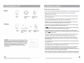
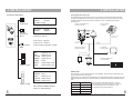
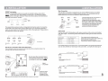
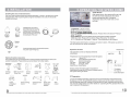
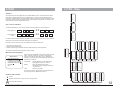
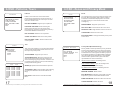
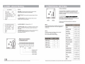
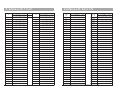
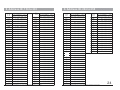
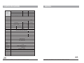
OKINA
High Speed Dome
Camera Series
User Manual
English
v2.33
WARNING
CONTENTS
TO REDUCE THE RISK OF FIRE OR ELECTRIC SHOCK, DO NOT EXPOSE THIS PRODUCT TO RAIN
OR MOISTURE. DO NOT INSERT ANY METALLIC OBJECTS THROUGH THE VENTILATION GRILLS OR
OTHER OPENINGS ON THE EQUIPMENT.
This symbol indicates that dangerous
voltage constituting a risk of electric
shock is present within this unit.
CAUTION: TO REDUCE THE RISK
OF ELECTRIC SHOCK, DO NOT
REMOVE COVER (OR BACK). NO
USER SERVICEABLE PARTS
INSIDE. JUST QUALIFIED
SERVICE PERSONNEL SHOULD
SERIVICE THE PRODUCT.
This symbol indicates that there are
important operating and maintenance
instructions in the literature
accompanying this unit.
FCC COMPLIANCE STATEMENT
FCC INFORMATION: THIS EQUIPMENT HAS BEEN TESTED AND FOUND TO COMPLY WITH THE
LIMITS FOR A CLASS A DIGITAL DEVICE, PURSUANT TO PART 15 OF THE FCC RULES. THESE
LIMITS ARE DESIGHEND TO PROVIDE REASONABLE PROTECTION AGAINST HAMRFUL
INTERFERENCE WHEN THE EQUIPMENT IS OPERATED IN A COMMERCIAL ENVIRONMENT. THIS
EQUIPMENT GENERATES, USES, AND CAN RADIATE RADIO FREQUENCY ENGERGY AND IF NOT
INSTALLED AND USED IN ACCORDANCE WITH THE INSTRUCTION MANUAL, MAY CAUSE
HARMFUL INTERFERENCE TO RADIO COMMUNICATIONS. OPERATION OF THIS EQUIPMENT IN A
RESIDENTIAL AREA IS LIKELY TO CAUSE HARMFUL INTERFERENCE IN WHICH CASE THE USER
WILL BE REQUIRED TO CORRECT THE INTERFERENCE AT HIS OWN EXPENSE.
1. Precaution......................................................
2. Features.........................................................
3. Packing list.....................................................
4. Installation.....................................................
5. Operating the Speed Dome..............................
6. OSD...............................................................
Map................................................................
System Setting................................................
Motion, Clear, Password..................................
Camera Setting...............................................
Preset, Scan...................................................
Platterns, Tours...............................................
Zones and Privacy Mask...................................
Alarm Setting...................................................
7. Protocol Setting...............................................
8. Address ID......................................................
9. Specifications.................................................
CAUTION: CHANGES OR MODIFICATIONS NOT EXPRESSLY APPROVED BY THE PARTY
RESPONSIBLE FOR COMPLIANCE COULD VOID THE USERS‘S AUTHORITY TO OPERATE THE
EQUIPMENT.
CE COMPLIANCE STATEMENT
WARNING: THIS IS A CLASS A PRODUCT. IN A DOMESTIC ENVIRONMENT THIS
PRODUCT MAY CAUSE RADIO INTERFERENCE IN WHICH CASE THE USER MAY BE
REQUIRED TO TAKE ADEQUATE MEASURES.
CAUTION: BEFORE ATTEMPTING TO CONECT OR OPERATE THIS PRODUCT, PLEASE
READ THE LABEL ON THE BOTTOM AND USER'S MANUAL CAREFULLY
Technical specification are subjects to change without
prior notification. Manual may contain mistakes or print errors.
All trade marks mentioned belong to their respective owners.
1
2
3
4
10
11
12
13
14
15
16
17
18
19
20
21
25
2.FEATURES
1.PRECAUTION
Refer all work related to the installaion of this product to qualified service
personnel or system installers.
Do not attemp to disassemble the appliance
To prevent electric shock, do not remove screws or cover. There are no userserviceable parts inside. Contact qualified service personnel for maintenance
Handle the appliance with Care
Do not strike or shake, as this may damage the appliance. It should be protected
against extreme pressure, vibration and humidity during transportation and storage.
Damages caused by improper transportation avoid the warranty.
Do not use strong or abrasive detergents when cleaning the appliance body and
transparent cover.
Use a dry cloth to clean the appliance when it is dirty. When the dirt is hard to remove,
use a mild detergent and wipe gently.
Do not operate the apliance beyond its speci?ed temperature, humidity or power
source ratings.
Do not use the dome camera in an extreme environment where high temperature or
high humidity exists.
Use the indoor models within -10°C to +50°C(14°F to 122°F) and a humidity below
90%. The input power source is 24V AC, 50/60Hz and requires 1000mA.
Use the outdoor models within -20°C to +60°C(-4°F to 140°F) and a humidity below
90%. The input power source is 24V AC, 50/60Hz and requires 2500mA.
Do not expose the indoor model of dome camera to water or moisture, not try to
operate it in wet areas.
Take immediate action when the indoor speed dome becomes wet. Turn off the power
and refer servicing to qulified service personnel. Moisture may damage the appliance
and cause eletric shock.
Do not point the camera lens directly to sunlight or any strong light source.
This will cause permanent damage to the camera and avoids the warranty.
Read this user's manual carefully before operating the appliance.
Make sure that local electric safty standard are followed when using or installing the
appliance
Do not install the camera in other orientation as designed.
And do not bend or squeez the sturctiure, as this may damage the mechanic sturcture
of the appliance and avoids the warranty.
The high speed dome camera series are designed for in- and outdoor video
surveillance application. The integrated, motorized pan-tilt mechanic allows user
to point the camera to any position( 360° horizontal and 180° vertical). Both series can
be equipped with digital zoom camera modules, which provide zooming functon from
18 to 36 times (optical) and advanced image features.
Key features:
- 360° Pan and 180° Tilt range (90° with auto-image-flip)
- Support most well-known camera modules
- 128 preset points memory (80 can be used for auto tour function)
- 4 pattern tours
- 4 Scan tour
- Basic setup directly from Keyboard.
- Advanced setup through OSD (On Screen Display) menu.
- up to 24 privacy masking zones ( despends on camera module)
- 7 alarm input & 2 outpu t ( 4 input & 1 output pre-wired)
- Multi-Protocol through RS485 or coaxial cable.
- Direction Indicator on screen
- Aluminum Alloy structure with high intensity and heat-sinking
- High-precision step-motor for flicker-less image during movement.
Camera Features:
-HighResolution with 520TVL and Wide-Dynamic*
- Auto-Focus
- Auto-Iris
- Auto- Brightness control,
- Auto-Balance
- IR cutter control, Day-Night mode switching. (Available in 36X only)
- Auto Slow-Shutter
Temperature monitoring and protection
- Alarm notification will be displayed once the inner temperature exceeds the limit
- In low temperature area, the dome camera will only start after the operation
temperature is reached.
- Cooling fan activity is managed by the CPU ( extends the duration)
Other features:
- Proportional pan for Focus / Speed on different zoom factor.
- Auto-resuming user-defined action, such as tour, pattern or scan after selectable idle
time.
- Power-up Action activates tour or pattern by default.
Do not touch the Cover with bare hands or any object.
These will scratch the serface and affect the image qulaity.
* depends on camera module type.
1
S o m e p r o d u c t s m a y n o t b e a v a i l a b l e i n y o u r c o u n t r y, p l e a s e c o n t a c t o u r d i s t r i b u t o r f o r m o r e d e t a i l s
S o m e p r o d u c t s m a y n o t b e a v a i l a b l e i n y o u r c o u n t r y, please contact our distributor for more details
2
4.INSTALLATION
4.INSTALLATION
Connector description
Power
Connector
Using optional accessories
RED
: AC 24V
BLACK
: AC 24V
To power supply
The speed dome camera series can be connected to various optional accessories
through the standard connector types, which simplifiy the cable handling and avoid
possible mistakes. All accessories are tested for max. Compatibility and best
performance.
Outdoor power adaptor box
AC 230V to AC 24V
3-Axis keyboard
controller
OK-P
TZ-K
RS 485
Connector
RJ-11
YELLOW
GREEN
: RS485 : RS485 +
AC 24 Power
supply
To keyboard or DVR devices for
telemetric control
RS 485
Telemetric control
camera setup
Alarm I/O
Video output
BNC
Alarm I/O (A)
Inner Conn : Signal +
Outer Conn : Ground
Video Output to monitor or DVR
: Alarm input 1
: Alarm input 2
: Alarm input 3
: Alarm input 4
: COM
: Alarm output - N.O.
: Alarm output - N.C.
AQUA
: N.C. 2
BROWN : N.O. 2
GRAY
: Alarm input 7
PURPLE : Alarm input 6
ORANGE : Alarm input 5
I/O interface to additional alarm
sensor or control devices
S o m e p r o d u c t s m a y n o t b e a v a i l a b l e i n y o u r c o u n t r y, p l e a s e c o n t a c t o u r d i s t r i b u t o r f o r m o r e d e t a i l s
21”High Res.
security monitor
AC 24 Power supply
Professional Real-time
16 Channel DVR
AC 230V
Power input
Video signal
RS485 cable
The telemetric control of the appliance uses RS485 serial communication with halfduplex transmission technology.
Depending on the cable type and baud rate, the transmission distance could vary. The
following table shows max. distances based on cable with 0,56mm (24AWG) twisted
pair:
Baud Rate
Alarm I/O (B)
5
RS 485
AC 230V
Power input
Indoor power adaptor
AC 230V to AC 24V
RED
PINK
YELLOW
GREEN
BLACK
WHITE
BLUE
B300
2400 bps
4800 bps
9600 bps
19200 bps
Max. Distance
1700m
1100 m
700m
Due the environmental interferences, such as
eletromagnetic and induction fields, or number of
connected appliance on the RS485 bus, the
transmission range may decrease.
400m
S o m e p r o d u c t s m a y n o t b e a v a i l a b l e i n y o u r c o u n t r y, please contact our distributor for more details
6
11
Symbols and indicator
Cursor.
Sub item is selected. use up or down to change value
Some products may not be available in your country, please contact our distributor for more details
MOTION
ON
ON
005
NONE
NONE
040
This item has subitem(s)
Some products may not be available in your country, please contact our distributor for more details
OLD PASSWORD :
NEW PASSWORD :
CONF PASSWORD :
BACK
EXIT
******
******
******
PASSWORD SETUP
CLEAR ALL ZONES
CLEAR ALL PRESETS
CLEAR ALL PATTERNS
CLEAR ALL TOURS
CLEAR ALL WINDOWS
FACTORY DEFAULTS
RESTART
BACK
EXIT
AUTO FLIP
PROPORTION PAN
PARK TIME
PARK ACTION
POWER UP ACTION
FAN
ENABLED
BACK
EXIT
OFF
OFF
OFF
OFF
OFF
OFF
LEFT:
DISPLAY SETUP
RIGHT:
- Moving between current menu items
- Changing the value in sub items
- Enter the selected menu item
- Confirm the value change and return to
item selection
- Exit from sub menu
DOME LABEL
PRESET LABEL
ZOOM LABEL
ZONE LABEL
DIRECTION LABEL
TEMPERATURE
LABEL
BACK
EXIT
UP, DOWN:
INFO
To solve this inability stop the operation and try again.
INITIAL
SYSTEM SETTING
CAMERA SETTING
FUNCTION SETTING
WINDOW BLANKING
ALARM
EXIT
SCAN
01
63
1
ZONES NUMBER
SET LEFT LIMIT
SET RIGHT LIMIT
CLEAR ZONE
E D I T Z O N E L A B E L→
BACK
EXIT
ZONES
TOUR NUMBER
E D I T T O U R→
RUN TOUR
CLEAR TOUR
BACK
EXIT
TOUR
1
PATTERN NUMBER
PROGRAM PATTERN
RUN PATTERN
CLEAR PATTERN
E D I T P A T T E R N L A B E L→
BACK
EXIT
PATTERNS
SCAN NUMBER
SCAN SPEED
SET LEFT LIMIT
SET RIGHT LIMIT
CLEAR SCAN
RUN SCAN
E D I T S C A N L A B E L→
BACK
EXIT
1
AUTO
SCAN
EDIT T O U R
P0-S- TM P0-S- TM
٠٠-٠- ٠٠ ٠٠-٠ - 00
٠٠-٠- ٠٠ ٠٠-٠ - 00
٠٠-٠- ٠٠ ٠٠-٠ - 00
٠٠-٠- ٠٠ ٠٠-٠ - 00
٠٠-٠- ٠٠ ٠٠-٠ - 00
LABEL: ZONE-1
BACK
EXIT
EDIT ZONE LABEL
P0-S- TM
٠٠-٠- ٠٠
٠٠-٠- ٠٠
٠٠-٠- ٠٠
٠٠-٠- ٠٠
٠٠-٠- ٠٠
BACK
EXIT
LABEL: PATTERN-1
BACK
EXIT
EDIT PATTERN LABEL
LABEL:
BACK
EXIT
EDIT SCAN LABEL
LABEL
Note that in some situations, it is not possible to access the OSD menu:
S P E E D D O M E V 2.33
P R O T O C O L : PELCO
DOME ADDRESS: 001
C O M M : 96 0 0 . N . 8 . 1
BACK
EXIT
Main Menu
After entering the OSD Menu, the screen will show menu
items . Use the controller’s joystick to navigate the
menu’s main and sub items by moving in the desired
direction. The angle mark on the beginning of every item
indicates the selection.
PRESET
1. The dome is running a tour
2. Performing PTZ operations
3. Dome is receiving a command other than OSD-request from the keyboard
EDIT
In case a DVR is used for operating the OSD, select “go to preset 95” or 2 X “go to preset 9”.
Please refer to the DVR’s operation manual for more details.
LABEL: PRESET-01
BACK
EXIT
Enter
001
9
PRESETS
Shot
PRESET NUMBER
SET PRESET
SHOW PRESET
CLEAR PRESET
E D I T P R E S E T L A B E L→
BACK
EXIT
2X
AUTO
N/A
N/A
N/A
AUTO
N/A
N/A
OFF
or
MODE
SHUTTER
IRIS
BRIGHT
WB MODE
R GAIN
B GAIN
HI-RESOLUION
BACK
EXIT
Enter
ADVANCE SETTING
5
AE
9
EDIT DOME LABEL
Shot
L A B E L : S P E E D D O M E 1.00
BACK
EXIT
With keyboard
WINDOW NUMBER
EDIT WINDOW
ENABLE WINDOW
CLEAR WINDOW
BACK
EXIT
ON
ALARMS
RESUME
RESET DELEY
ALARM CONTACT
ALARM SETTING→
BACK
EXIT
Enter
01
9
BLANKING
call
WINDOW
2X
SETTING
or
FUNCTION
To start the OSD Menu, you need to press the following sequence on the keyboard:
PRESETS→
SCAN→
PATTERNS→
TOUR→
ZONES→
BACK
EXIT
Enter
CAMERA SETTING
OFF
030
N/O
How to start the OSD Menu
ZOOM SPEED
HIGH
DIGITAL ZOOM
ON
BLC MODE
OFF
SLOW SHUTTER
ON
IR CUT FILTER
AUTO
LI)NE SYNC
OFF
WDR MODE
ON
ADVANCE SETTING →
BACK
EXIT
5
SETTING
9
SYSTEM
ALARM NUMBER
ALARN ACTION
ACTIVATE AUXT
BACK
EXIT
ALARMS SETTING
001
NONE
OFF
The speed dome are equipped with the new OSD Menu function. All operational functions
and camera related settings can be controlled here. In order to use the OSD function, a
telemetric controller device, such as keyboard, DVR or other devices with similiar functions,
is required. Please make sure that the device used is properly physically connected to the
dome and all connection parameters are set.
EDIT DOME LABEL →
INITIAL INFO →
DISPLAY SETUP →
MOTION →
CLEAR →
PASSWORD SETUP →
BACK
EXIT
Main menu and navigation
MENU
call
MAIN
(3-Axis)
With keyboard
SYSTEM SETTING →
CAMERA SETTING →
FUNCTION SETTING →
WINDOW BLANKING →
ALARMS →
EXIT
6.OSD
6.OSD - Map
OSD Menu
For more inforamtion, please refer to the illustration on
the next page for the OSD Menu structure.
12
6.OSD - System Setting
System Setting
SYSTEM SETTING
In the system setting menu, you can modify operation
and display settings, such as dome label, temperature
and display of various values on the operational
screen.
EDIT DOME LABEL
INITIAL INFO
DISPLAY SETUP
MOTION
CLEAR
PASSWORD SETUP
BACK
EXIT
6.OSD - Motion, Clear, Password
Motion control
MOTION
AUTO FLIP
PROPORTION PAN
PARK TIME
PARK ACTION
POWER UP ACTION
FAN ENABLED
BACK
EXIT
ON
ON
005
SCAN
AUTO
040
Dome Label:
EDIT DOME LABEL
LABEL: ENTRANCE
BACK
1.
2.
3.
4.
use
use
use
use
UP or DOWN to change the character.
RIGHT to move to next character.
RIGHT to move to last char. and to save.
Left to go to first char. and to cancel.
EXIT
CLEAR
INITIAL
INFO
Initial Info:
Shows the information about current settings.
FIRMWARE V 2:33
PROTOCOL:FACTORY
DOME ADDRESS:001
COMM:4800,N,8,1
BACK
EXIT
13
OFF
OFF
ON
OFF
ON
OFF
Enables the display for the on-screen info during
operaton mode.
Dome label: Name of the dome
Preset label: Shows the label of every preset
Zoom label: Shows zoom factor on screen
Zone label: Shows the zone name
Direction label: Shows the coordinates
Temperature label: Shows the current temp. in
the dome
Some products may not be available in your country, please contact our distributor for more details
Clear
You can clear setting’s memory or reset the camera to
factory default. The follwing functions are supported:
-
Clear all zones
Clear all presets
Clear all patterns
Clear all tours
Clear all windows
Factory defaults
Warning: The clear action cannot be undone.
Once an item is cleared it is impossible to
retrieve the deleted setting. Please make sure
that the requested clear action is desired.
Display Setup
DISPLAY SETUP
DOME LABEL
PRESET LABEL
ZOOM LABEL
ZONE LABEL
DIRECTION LABEL
TEMPRATURE LABEL
BACK
EXIT
CLEAR ALL ZONES
CLEAR ALL PRESETS
CLEAR ALL PATTERNS
CLEAR ALL TOURS
CLEAR ALL WINDOWS
FACTORY DEFAULTS
RESTART
BACK
EXIT
AUTO FLIP : Auto. image flip , tilt range from 90° to
180°.
PROPORTIONAL PAN: Depending on the zoom
factor, the dome will adjust the pan and tilt speed
automatically for comfortable viewing.
PARK TIME: Defines the idle time prior to start a
custom defined action (park action).The duration can
vary from 1 to 240 minutes. This function can
bedisabled by setting the minute to 0.
PARK ACTION: The action which will be started after
the idle time (park time). Selectable between Preset,
Scan, Pattern (Nr), Tour or None.
POWER UP ACTION: Action which starts after power
up and self test. Selectable between Auto, Preset 1,
Scan, Pattern (Nr), Tour or None. By selecting Auto,
the dome will resume the last action before power off.
FAN ENABLED : Defines the temperature limit (in °C)
at which the internal cooling starts operating. The
standard limit is 40°C.
PASSWORD SETUP
O LD PASSWORD : ******
NEW PASSWORD : ******
CONF PASSWORD : ******
ENABLE PASSWORD OFF
BACK
EXIT
Password setup
You can change password to access the OSD menu.
Default Password is 000000.
Some products may not be available in your country, please contact our distributor for more details
14
6.OSD - Patterns, Tours
Patterns
PATTERNS
Patterns record the user’s movement while
performing PTZ operations and stores them as a
track. The Speed Dome can record up to 4 tracks
with max. 180 sec. each.
PATTERN NUMBER 1
PROGRAM PATTERN
RUN PATTERN
CLEAR PATTERN
EDIT PATTERN LABEL
BACK
EXIT
PATTERN NUMBER: Supports up to 4 patterns.
6.OSD - Zones and Privacy Mask
ZONES
ZONE NUMBER
1
SET LEFT LIMIT
SET RIGHT LIMIT
CLEAR ZONE
EDIT ZONE LABEL
BACK
EXIT
PROGRAM PATTERN: Starts recording the
pattern when selected. You can perfom PTZ
movements for recording (not exceeding 180 sec.).
Press IRIS-OPEN to save the track.
Zones
You can define the zones in the whole PT range up to
8 zones. When the display setting “Zone Label” is
activated, its label will be displayed on the screen.
The defined ranges of the zones should not be
overlapping.
ZONE NUMBER: Supports up to 8 zones.
SET LEFT LIMIT: Left boarder of the current zone.
SET RIGHT LIMIT: Right boarder of the current zone.
CLEAR ZONE: Delet the current zone.
RUN PATTERN: Starts the current pattern.
EDIT ZONE LABEL : Changes the label (name) of the
current zone.
CLEAR PATTERN: Deletes the current pattern.
EDIT PATTERN LABEL : Sets the name for the
current pattern.
TOURS
TOUR NUMBER
EDIT TOUR
RUN TOUR
CLEAR TOUR
BACK
EXIT
Tour
1
Tour is an auto-operation running through selected
preset points with definable pause time. A tour can
store up to 24 preset points.
TOUR NUMBER: Supports up to 4 tours.
TOUR PRESETS (P0): Move the joystick up and
down to select the preset points by number and
save the settings by going to the left end of the line.
If a selected point has the value 0, all the following
preset points will be ignored.
EDIT
TOUR
PO-S-TM PO-S-TM PO-S-TM
00-0-00 00-0-00 00-0-00
00-0-00 00-0-00 00-0-00
00-0-00 00-0-00 00-0-00
00-0-00 00-0-00 00-0-00
00-0-00 00-0-00 00-0-00
00-0-00 00-0-00 00-0-00
00-0-00 00-0-00 00-0-00
00-0-00 00-0-00 00-0-00
BACK
EXIT
17
SPEED (S): Speed of the dome between 2 points.
WINDOW BLANKING
WINDOW NUMBER 01
EDIT WINDOW
ENABLE WINDOW OFF
CLEAR WINDOW
BACK
EXIT
Privacy Mask (Window Blanking)
Privacy Mask is used to protect the privacy area that
should not be displayed once the camera is pointed
on it, such as lavatory areas or the operation desk of
an ATM machine. This might be mandatory required
by local law regulations. The Speed Dome supports
up to 24 private masks (depending on the installed
camera module; please contact your local sales
representative for more information).
Hitachi camera modules : 8 masking areas
Sony Camera modules: up to 24 masking areas
(except the 45 series provides only 8)
LG,CNB Camera modules: no masking function
TOUR DWELL (TM): Pause duration after reaching
a preset point. Duration can be set between 0060(s).
RUN TOUR: Starts the tour and exits the OSD
Menu.
Some products may not be available in your country, please contact our distributor for more details
WINDOW NUMBER: Mask number.
EDIT WINDOW: Edit position of the mask using the
keyboard’s joystick. Presse IRIS-OPEN to save.
ENABLE WINDOW: Shows the mask on the screen.
CLEAR WINDOW: Deletes the mask.
Some products may not be available in your country, please contact our distributor for more details
18
8. Address ID, 1 to 67
ID
1
2
3
4
5
6
7
8
9
10
11
12
13
14
15
16
17
18
19
20
21
22
23
24
25
26
27
28
29
30
31
32
33
Switchnumber (Sw1)
Bit 1 2 3 4 5 6 7 8
00000000
10000000
01000000
11000000
00100000
10100000
01100000
11100000
00010000
10010000
01010000
11010000
00110000
10110000
01110000
11110000
00001000
10001000
01001000
11001000
00101000
10101000
01101000
11101000
00011000
10011000
01011000
11011000
00111000
10111000
01111000
11111000
00000100
10000100
8.Address ID, 68 to 135
ID
34
35
36
37
38
39
40
41
42
43
44
45
46
47
48
49
50
51
52
53
54
55
56
57
58
59
60
61
62
63
64
65
66
67
Switchnumber (Sw1)
Bit 1 2 3 4 5 6 7 8
01000100
11000100
00100100
10100100
01100100
11100100
00010100
10010100
01010100
11010100
00110100
10110100
01110100
11110100
00001100
10001100
01001100
11001100
00101100
10101100
01101100
11101100
00011100
10011100
01011100
11011100
00111100
10111100
01111100
11111100
00000010
10000010
01000010
11000010
Some products may not be available in your country, please contact our distributor for more details
ID
68
69
70
71
72
73
74
75
76
77
78
79
80
81
82
83
84
85
86
87
88
89
90
91
92
93
94
95
96
97
98
99
100
101
Switchnumber (Sw1)
Bit 1 2 3 4 5 6 7 8
00100010
10100010
01100010
11100010
00010010
10010010
01010010
11010010
00110010
10110010
01110010
11110010
00001010
10001010
01001010
11001010
00101010
10101010
01101010
11101010
00011010
10011010
01011010
11011010
00111010
10111010
01111010
11111010
00000110
10000110
01000110
11000110
00100110
10100110
ID
102
103
104
105
106
107
108
109
110
111
112
113
114
115
116
117
118
119
120
121
122
123
124
125
126
127
128
129
130
131
132
133
134
135
Switchnumber (Sw1)
Bit 1 2 3 4 5 6 7 8
01100110
11100110
00010110
10010110
01010110
11010110
00110110
10110110
01110110
11110110
00001110
10001110
01001110
11001110
00101110
10101110
01101110
11101110
00011110
10011110
01011110
11011110
00111110
10111110
01111110
11111110
00000001
10000001
01000001
11000001
00100001
10100001
01100001
11100001
Some products may not be available in your country, please contact our distributor for more details
8. Address ID, 204 to 255
8. Address ID, 136 to 203
ID
136
137
138
139
140
141
142
143
144
145
146
147
148
149
150
151
152
153
154
155
156
157
158
159
160
161
162
163
164
165
166
167
168
169
Switchnumber
Bit 1 2 3 4 5
00010
10010
01010
11010
00110
10110
01110
11110
00001
10001
01001
11001
00101
10101
01101
11101
00011
10011
01011
11011
00111
10111
01111
11111
00000
10000
01000
11000
00100
10100
01100
11100
00010
10010
(Sw1)
678
001
001
001
001
001
001
001
001
001
001
001
001
001
001
001
001
001
001
001
001
001
001
001
001
101
101
101
101
101
101
101
101
101
101
ID
170
171
172
173
174
175
176
177
178
179
180
181
182
183
184
185
186
187
188
189
190
191
192
193
194
195
196
197
198
199
200
201
202
203
Switchnumber
Bit 1 2 3 4 5
01010
11010
00110
10110
01110
11110
00001
10001
01001
11001
00101
10101
01101
11101
00011
10011
01011
11011
00111
10111
01111
11111
00000
10000
01000
11000
00100
10100
01100
11100
00010
10010
01010
11010
Some products may not be available in your country, please contact our distributor for more details
(Sw1)
678
101
101
101
101
101
101
101
101
101
101
101
101
101
101
101
101
101
101
101
101
101
101
011
011
011
011
011
011
011
011
011
011
011
011
ID
204
205
206
207
208
209
210
211
212
213
214
215
216
217
218
219
220
221
222
223
224
225
226
227
228
229
230
231
232
233
234
235
236
237
Switchnumber
(Bit)1 2 3 4 5
00110
10110
01110
11110
00001
10001
01001
11001
00101
10101
01101
11101
00011
10011
01011
11011
00111
10111
01111
11111
00000
10000
01000
11000
00100
10100
01100
11100
00010
10010
01010
11010
00110
10110
(Sw1)
678
011
011
011
011
011
011
011
011
011
011
011
011
011
011
011
011
011
011
011
011
111
111
111
111
111
111
111
111
111
111
111
111
111
111
ID
238
239
240
241
242
243
244
245
246
247
248
249
250
251
252
253
254
255
Switchnumber (Sw1)
(Bit)1 2 3 4 5 6 7 8
01110111
11110111
00001111
10001111
01001111
11001111
00101111
10101111
01101111
11101111
00011111
10011111
01011111
11011111
00111111
10111111
01111111
11111111
Some products may not be available in your country, please contact our distributor for more details
24
9.SPECIFICATION
Model
NOTES
OK-SEM18I-V48DN
OK-SEM26I-V48DN OK-SEMW36I-V53DN
OK-SEM18S-V48DN
OK-SEM26S-V48DN OK-SEMW36S-V53DN
OK-SEM18HB-V48DN
OK-SEM26HB-V48DN
OK-SEMW36HB-V53DN
Day / Night
Day / Night
Day / Night
Signal Format
PAL / NTSC
Progressive
Scanning
Image Sensor
1/4 inch Ex-View CCD
H. Resolution
48.0° (Wide end)
54.2° (Wide end)
2.8° (Tele end)
Zoom
Min. Illumination
Shutter Speed
Iris Control
57.8° (Wide end)
1.7° (Tele end)
2.2° (Tele end)
18× Opt. / 12× Digital
26× Opt. / 12× Digital
36× Opt. / 12× Digital
0.7 Lux (1/50 sec., Color)
Day: 0.7Lx (1/50), 0.1Lx (1/3)
Day: 2.0Lx (1/50), 0.14Lx (1/3)
Day: 1.4Lx (1/50), 0.1Lx (1/3)
-
Night: 0.01Lx (1/3)
Night: 0.7Lx (1/50), 0.05Lx (1/3)
Night: 0.01Lx (1/3)
Focus
White Balance
530 TVL
(High Resolution)
470 TVL, 440K Pixels (PAL)
Viewing Angle
Auto / Manual
Auto / Manual (ATW, Indoor, Outdoor, One Push WB, Manual WB)
Wide Dynamic Function (Sb36 / Wb36 models)
1 to 1/10,000 Sec.
1/3 to 1/10,000 Sec.
Auto / Manua/ Auto Slow Shutter
IR Cutter Control
N/A
Yes
Day/Night Mode
N/A
Yes
Gain Control
Auto / Manual (-3 to 28 dB, 2 dB steps, 16steps)
Video Output
VBS: 1.0Vp-p (Sync Negative), Y / C Output
S/N Ratio
More than 50 dB
Pan Speed
0.4° - 300° per Sec.
Tilt Speed
0.4° - 150° per Sec.
Pan Range
360°
Tilt Range
0 - 90°
Communication
Preset Positions
Auto Pan
Tour / Sequence
Alarm inputs
Operating Temp.
Power
25
RS485, multiple-protocol, coax
128 Presets
Yes, between 2 presets
4 progr. Tours with max 24 presets/ 4 Pattern up to 180s
7 inputs / 2 output
Outdoor: -40°C to 60°C / Indoor: -10℃ to50℃
24V AC / 24 -60 VA (outdoor)
Some products may not be available in your country, please contact our distributor for more details
26
Some products may not be available in your country, please contact our distributor for more details