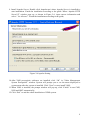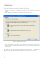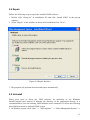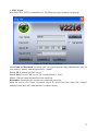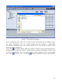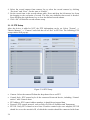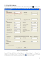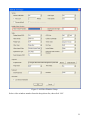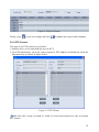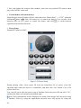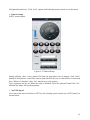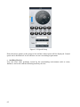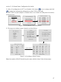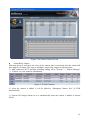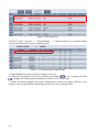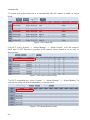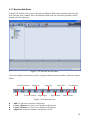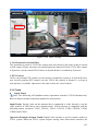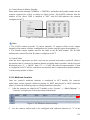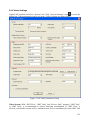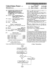
1
V2216
Network Video Management Software
Operation Manual
Revision History
Issue Date
Version
2012-02-17
2.23.01
2012-07-31
2.25.01
2012-10-24
2.25.04
Notes
1. Relevant description of decoding optimization is
added in Section 3.2.1 Video Playing and Section
3.2.5 Playback;
2. Chapter 2 Software Installation is newly added;
3. Section 1.3 System Configuration is newly added;
4. "Decode Optimize Type” is a newly added parameter
in Section 3.4.4 Video Settings.
1. Revise the default user name and password to
"Admin" and "123456" respectively;
2. ACS module is newly added;
3. Revise the descriptions of software installation and
uninstall in Chapter 2;
4. Section 3.1.17 Alarm Name Configuration is newly
added;
5. Section 4.4 V2216-R400 Network Video Management
Server (Optional) is newly added;
6. Revise parts of descriptions in section 4.2 FAQ;
7. The descriptions of alarm transmit are added in
section 3.1.21 Alarm Manage.
8. Section 3.1.11 CGI Tool is newly added;
9. Change the title of section 3.4.3 Device Detection to
3.4.3 System Setting, and the description of Resume
Default and Resume the Video Connection is newly
added.
10. Section 3.4.5 Instant Replay is newly added.
11. Revise the description of section 3.3.1 E-map.
12. Revise the description of section 3.4.4 Video
Settings.
13. Revise the description of section 3.2.3 PTZ Control.
14. In section 3.2.2 Video Switch, Display Setup is
newly added.
1. Revise the figures and description of section 3.1.7
SMT Setup and 3.1.8 NVR Setup.
2. Revise the figure of section 3.3.6 Alarm Contact.
Note
Copyright Statement
This manual may not be reproduced in any form or by any means used to create any
derivative such as translation, transformation, or adaptation without the prior written
permission of Infinova.
Infinova reserves the right to change this manual and the specifications without prior notice.
The most recent product specifications and user documentation for all Infinova products are
available on our web site http://www.infinova.com.
Trademarks
is a trademark of Infinova.
Copyright © 1993-2014 Infinova. All rights reserved.
All other trademarks that may appear belong to their respective proprietors.
About This Manual
This manual mainly introduces the system management and applications for V2216
Network Video Management Software. You can read every chapter as per sequence or you
can find the information you need through the Table of Contents.
This manual can be used together with V2216-LMC (Live Monitor Client) Quick Start
Guide for Users and V2216 Network Video Management Software Quick Start Guide for
Administrators.
Symbols and Conventions
Before using the V2216 system, please familiarize yourself with MS Windows system
operations, especially the mouse operations (click, double-click, right-click and wheel
button rotating) and program management (program installation, running and uninstall).
Icons
Note, to help you use the product more efficiently.
Warning, indicating that this may lead to hardware damage or data loss, and to suggest
how to prevent.
Prohibit, indicating that this may lead to loss of property, injury or death. Use with care.
Table of Contents
Chapter 1 About V2216 ...................................................................................................... 1
1.1 Overall Introduction.................................................................................................... 1
1.2 System Introduction.................................................................................................... 2
1.3 System Configuration ................................................................................................. 3
Chapter 2 Software Installation......................................................................................... 5
2.1 Install Database........................................................................................................... 5
2.2 Install VMS Software ................................................................................................. 7
2.3 Modification ............................................................................................................. 10
2.4 Repair........................................................................................................................ 11
2.5 Uninstall.................................................................................................................... 11
2.6 Remote Automatic Update ........................................................................................ 12
Chapter 3 System Functions ............................................................................................ 13
3.1 Basic System Configuration...................................................................................... 13
3.1.1 District and Device Organization ................................................................... 13
3.1.2 Authorization Information License ................................................................ 14
3.1.3 Logon............................................................................................................. 14
3.1.4 Area Setup...................................................................................................... 18
3.1.5 Area E-map Setup .......................................................................................... 19
3.1.6 Device Setup .................................................................................................. 19
3.1.7 SMT Setup ..................................................................................................... 22
3.1.8 NVR Setup..................................................................................................... 24
3.1.9 Name of Digital Devices and LMC Software ................................................ 25
3.1.10 SNMP Setup................................................................................................. 25
3.1.11 CGI Tool ...................................................................................................... 31
3.1.12 Auto-record Setup ........................................................................................ 33
3.1.13 PTZ Setup .................................................................................................... 34
3.1.14 User Setup.................................................................................................... 35
3.1.15 User Group Setup......................................................................................... 36
3.1.16 Assign User to User Group .......................................................................... 37
3.1.17 Link User Group with Area.......................................................................... 37
3.1.18 Alarm Name Configuration.......................................................................... 38
3.1.19 Set LMC to Monitor..................................................................................... 39
3.1.20 Backup and Restore Database ...................................................................... 40
3.1.21 Redundancy Function Setup ........................................................................ 40
3.1.22 Alarm Manage.............................................................................................. 42
3.2 Basic System Functions ............................................................................................ 48
3.2.1 Video Playing................................................................................................. 48
3.2.2 Video Switch.................................................................................................. 52
3.2.3 PTZ Control ................................................................................................... 59
3.2.4 Record ............................................................................................................64
3.2.5 Playback .........................................................................................................65
3.2.6 Encoding Device Alarm..................................................................................71
3.3 Advanced System Functions......................................................................................75
3.3.1 E-map .............................................................................................................75
3.3.2 Two-way Audio ..............................................................................................78
3.3.3 Access Control Alarm.....................................................................................84
3.3.4 Matrix Alarm ..................................................................................................86
3.3.5 V2431Alarm Interface Unit Alarm .................................................................88
3.3.6 Alarm Contact.................................................................................................89
3.3.7 Monitor Wall Mode ........................................................................................99
3.3.8 CMS Cascading............................................................................................101
3.3.9 Trunk ............................................................................................................107
3.3.10 Multicast Function...................................................................................... 115
3.4 Other Functions ....................................................................................................... 117
3.4.1 Exit ............................................................................................................... 117
3.4.2 Lock and Unlock Screen............................................................................... 119
3.4.3 System Setting..............................................................................................121
3.4.4 Video Settings...............................................................................................123
3.4.5 Instant Replay...............................................................................................124
3.4.6 Device Information Viewing ........................................................................125
3.4.7 Snapshot View ..............................................................................................125
3.4.8 Log View ......................................................................................................129
3.4.9 Alarm Manage ..............................................................................................131
3.4.10 WEB Introduction.......................................................................................132
Chapter 4 Appendix ........................................................................................................138
4.1 Time Synchronization Server Setup ........................................................................138
4.2 FAQ .........................................................................................................................139
4.3 Operating Environment ...........................................................................................148
4.4 V2216-R400 Network Video Management Server ..................................................150
Chapter 1 About V2216
1.1 Overall Introduction
The V2216 Network Video Management Software is graphical user interface software,
which consists of seven modules: Central Management Server (CMS), Alarm Center Server
(ACS), Stream Media Transmission (SMT), Network Video Recorder (NVR), Network
Configuration Tool (NCT), Live Monitor Client (LMC) and Multicast Player (MCP).
The V2216 software package includes 7 individual modules:
V2216-CMS: Central Management Server;
V2216-ACS: Alarm Center Server;
V2216-SMT: Stream Media Transmission;
V2216-NVR: Network Video Recorder;
V2216-NCT: Network Configuration Tool;
V2216-LMC: Live Monitor Client;
V2216-MCP: Multicast Player.
Infinova V2216 Network Video Management Software is Windows based and is designed
in modules. With Central Management Server as the core, flexible network construction,
the software can provide you with excellent network video surveillance solution. With
management of up to 9999 videos, the software can be applied in large, medium and small
applications.
The Stream Media Server module of V2216 software can solve the problems caused by
simultaneous access of many users or insufficient network bandwidth. The software
supports up to 100 Stream Media Servers, and each server supports transmission of up to
150 videos simultaneously, greatly improve the use of video resources.
V2216 can manage a maximum of 100 Network Video Recorders. Each recorder supports
recording of up to 100 videos as well as dynamic assignment of recording channels;
Manual recording, auto recording and pre-alarm recording functions are provided. And the
network video recorder supports ISCSI network disk array.
V2216 Alarm Center Server supports alarm input from third party alarm devices, and can
analyze the alarm information and realize alarm interaction, so as to control the third party
alarm devices.
V2216 supports multiple Live Monitor Clients, with maximum user number of 500. And
each client software provides viewing of 36 videos. And, multi-monitor output function is
available, which is very convenient for TV wall output and video viewing. Functions such
as searching, replay, map and virtual keyboard are also provided.
1
V2216 Matrix inherits major functions from Infinova video matrix switcher, such as system
tour, Salvo, event timer and alarm. With the software, Infinova digital and analog
surveillance systems can be integrated seamlessly. And the software allows network
keyboard to control the system. The operation of V2216 is as easy and convenient as analog
video matrix, meeting users’ operation practice.
1.2 System Introduction
Front-end: To meet different demands of actual surveillance environment, V2216 system
not only support platform management of all digital devices, but also can integrate the
existing analog devices with V2216 platform seamlessly. However, with the rapid
development of IP HD (high-definition) devices, EPON system can assure the bandwidth
and punctuality of HD video transmission.
Surveillance Area
z Area A: EPON transmission system is included to meet bandwidth requirement and
provide high real-time HD video;
z Area B: Full IP front-end network;
z Area C: The integration of analog matrixes with digital platform, to convert analog
signal to digital signal and integrate it into V2216 system.
Servers: It is responsible for the data management/storage and video transmission of the
whole surveillance system. All users’ access priority is verified via CMS, which also deal
with control signals from other modules; ACS supports alarm input from third party alarm
devices, can analyze the alarm information and realizes alarm interaction, so as to control
the third party alarm devices; live video and record video are transmitted via SMT;
centralized storage and video playback are performed via NVR and professional IPSAN
storage devices. A backup CMS is added to realize redundant function to assure system
stability. Besides, a router with multicast function is added to play multicast audio/video
stream by SMT and play video with MCP (multicast player) to save bandwidth.
2
Surveillance Center: As the surveillance center for the whole system, it provides the
functions of live viewing, PTZ control, Alarm, E-map, query and so on.
1.3 System Configuration
Recommended PC Configuration for Client-end PC (NCT/LMC)
CPU: ≥2.83GHz, Intel®Core™[email protected],3.40GHz is recommended to view
8*1080P videos simultaneously. User can configure CPU according to the videos needed.
Memory: ≥4G
Network Adapter: 1000Mbps, Ethernet
Independent Display Card: display memory ≥ 256M
Operating System: Windows XP (32 bits, ≥SP3)/ Windows7 (32 bits), support Chinese,
English and Traditional Chinese versions
Recommended PC Configuration for Servers
V2216 Professional (CMS/SMT/NVR)
CPU: ≥2.4GHz
Server Recommended: DELL R710
Memory: 4G
Network Adapter: ≥2000Mbps, Ethernet
Operating System: Windows 2003 Server (32 bits)/ 2008 Server (32 bits), support Chinese,
English and Traditional Chinese versions
Note: It is strongly recommended to install CMS, SMT and NVR in the same server, which
supports up to 128 videos.
V2216 Enterprise (CMS/SMT/NVR)
CMS Server: supports up to 9999 videos
CPU: ≥2.4GHz
Server Recommended: DELL R710
Memory: 4G
Network Adapter: 1000Mbps, Ethernet
Operating System: Windows 2003 Server (32/64 bits)/ 2008 Server (32/64 bits), support
Chinese, English and Traditional Chinese versions
SMT/NVR Server: SMT server supports up to 150 videos (D1, 2M code stream); NVR
server supports up to 100 videos (D1, 2M code stream).
CPU Nominal Frequency: ≥2.4GHz
Server Recommended: DELL R410/R710
Memory: 4G
Network Adapter: ≥2000Mbps, Ethernet
Operating System: Windows 2003 Server (32/64 bits)/ 2008 Server (32/64 bits), support
Chinese, English and Traditional Chinese versions
3
Note: It is strongly recommended to install CMS in a separate server, and then install SMT
and NVR in the same server. Multiple suits of SMT/NVR can be installed if there are many
surveillance sites
4
Chapter 2 Software Installation
The installation process includes “Install Database” and “Install VMS”. If CMS installation
is needed, Install database before install CMS. If not, just install VMS directly.
2.1 Install Database
VMS supports database of SQL Server 2008 and SQL Server 2005 Express.
Note: To avoid conflict, do not run these two database’s service at the same time when
installing database and running CMS.
If SQL Server is installed already, click “Install Database”, the following step 2, 3, and 4
will be skipped.
1. Double click “Setup.exe” in the installation file to display the installation window, as
shown below:
Figure 2-1 Installation Window
2. Click “Install Database” and system will give the prompt of “Database(Item) is not
5
installed”, then click “Yes” to move to the next step;
3. Install WindowInstaller3.1. If WindowsInstaller3.1 is not installed, system will prompt
you to install it according to the guide. If it is installed already, move to the next step
directly;
4. Enter Microsoft. NET Framework 2.0 installation programs. If it is not installed by user,
system will install it automatically. If it is already installed, user can select “Restore” to
install it or click “Cancel” to move to the next step directly;
5. SQL 2005 Express will be installed automatically. When the installation is finished, the
window that prompts you to install database will pop up, as shown below. Input correct
Server Name, User ID and Password, and then click “Ok” to start installation.
Figure 2-2 Install Database
6. System will prompt you that installation is successful after the database is installed. Click
“Exit” to exit the installation interface.
6
2.2 Install VMS Software
1. Run “Setup.exe” and click “Install VMS” in the installation window, select installation
language in language selection window, then click “Ok”;
Figure 2-3 Installation Language
2. Welcome interface will pop up, click “Next”;
3. Click “Yes” to accept installation protocol;
4. Select installation path for VMS software. If path modification is needed, click
“Browse” to set it, and then click “Next”;
5. In module selection window, as shown in Figure 2-4, select the modules to be installed,
then click “Next”;
Figure 2-4 Install Modules
7
Note: Only if CMS module is selected to install, system will perform installation
detection for prerequisite software. If prerequisite software is not installed, the window to
install it will pop up.
6. If CMS module is selected to be installed and prerequisite software of VMS is not
installed, the window to install prerequisite software will pop up, as shown below. Select
the link for the prerequisite software and run programs in the pop-up file. Finish the
installation according to the guide;
Figure 2-5 Install Prerequisite Softwares
7. Install WinPcap. Double click WinPcap.exe where WinPcap is installed to run
installation programs. Finish the installation according to the guide;
8. Install EnterSafe ePass2001. Double click ePass2001.exe where ePass is installed to run
installation programs. Finish the installation according to the guide;
8
9. Install Apache Server. Double click Aapache.msi where Apache Server is installed to
start installation. Finish the installation according to the guide. When “Apache HTTP
Server2.2” window pops up, as shown in Figure 2-6, input correct information and
select “’ for all users”. Finish the installation according to the guide;
Figure 2-6 Apache Setting
10.After VMS prerequisite softwares are installed, click “Ok” in “Video Management
System Prerequisite” window. System will prompt you to set the name displayed in
system menu after the system is installed. Click “Next” to start install VMS;
11.When VMS is installed, the prompt window will pop up, click “Finish” to run CMS,
NVR and SMT automatically;
12.Click “Exit” to end the whole installation of VMS system.
9
2.3 Modification
Follow the following steps to modify the installed VMS software:
1. Double click “Setup.exe” in installation file and click “Install VMS” in the pop-up
window;
2. Select “Modify” in the window as shown below and then click “Next”;
Figure 2-7 Modification Interface
3. Select the functions to be added in the function selection interface. Deselect the
functions which are installed but unneeded. Click “Next” and system will modify VMS
automatically.
Note: It is not suggested to modify VMS from “Control Panel” → “Add/Remove
Programs”. Otherwise, the “Add/Remove Programs” interface can not be operated.
10
2.4 Repair
Follow the following steps to repair the installed VMS software:
1. Double click “Setup.exe” in installation file and click “Install VMS” in the pop-up
window;
2. Select “Repair” in the window as shown below and then click “Next”;
Figure 2-8 Repair Interface
3. The program will perform detection and repair automatically.
2.5 Uninstall
When users need to delete the VMS software, do remember to use Windows
Install/Uninstall tools instead of deleting the directory of the application directly. It is
recommended to close the running VMS modules before uninstall it. Follow the following
three different means to uninstall VMS system.
1. In Windows system, click “Start” → “All Programs” → “Video Management System” →
11
“Uninstall”, uninstall VMS according to the guide.
2. Open “Control Panel” and click “Add or Remove Program”, select “VMS software” in the
Change or Remove Programs window. Click Change/Remove program button and the
VMS software will be removed.
3. Uninstall it via installation program. Click “Remove” button in Figure2-9 to uninstall it
according to the guide.
2.6 Remote Automatic Update
If you have already installed the old version of VMS and now need the new version of
VMS, remote automatic update function enables you to update quickly, the procedures are
shown below:
1. Uninstall the VMS software included in the server of old version of CMS module
(including backup CMS). If the old database needs to be reserved, please backup it in old
version;
2. Install new version of CMS module and the VMS software module uninstalled, and then
restart CMS server.
After the above procedures are finished, the CMS will update all other modules when they
log on CMS. No manual update for respective module is needed. The computer restarts
automatically after the NVR, SMT, NCT, ACS and/or LCM modules are updated.
Note: Only if the old and the new version both support Remote Automatic Update, can
this chapter be applicable.
12
Chapter 3 System Functions
3.1 Basic System Configuration
3.1.1 District and Device Organization
Note: This section is for reference only. Skip this section if you have your district and
devices well organized.
Area setup facilitates the management of encoders, decoders, matrix switchers, access
control systems, keyboards and software in an area of a security surveillance district. The
Area of V2216 is set to manage them in centralized way.
As shown in Figure 3-1, a surveillance district that is managed by V2216 software can be
divided into several areas, and each area can be divided into sub-areas. So, the surveillance
district should be well organized before V2216 system setup. When the district is well
configured, it is available to logon NCT module to perform area setup.
Figure 3-1 Surveillance District
13
3.1.2 Authorization Information License
Click “System Setting”, the current authorization information will be displayed in the
“Authorization Information” section, such as Figure 3-2.
Figure 3-2 "CMS" → "System Settings" → "Authorization Information"
If you have not bought INFINOVA V2216 authorization license, system permits you to
take a trial period of 30 days, with 16 camera licenses (camera of digital encoding
device).
If you have already bought INFINOVA V2216 authorization licenses, please insert USB
Key to USB port, the system will verify the authorization automatically.
If the INFINOVA V2216 authorization licenses you bought with 0 day left or the
permissive cameras are too limited, you can apply to buy new licenses. When you get the
new authorization files, click “Select”, and select the new authorization files on the
pop-up window, then click “Update”. After the successful update, the system will prompt
you to restart the computer, please restart the computer by hand to make the new
authorization files take effect.
z
z
z
3.1.3 Logon
If the NVR and SMT modules have already been added to NCT, user will logon them
automatically once the PC starts as well. If ACS doesn't start, user need click ACS
icon in the lower right corner of the window to start up. User has to logon NCT
and LMC modules by hand.
14
z NCT Logon
Start Infinova V2216 NCT Client to enter “Log On” interface, as shown below:
Figure 3-3 Log On Interface
User Name and Password: At initial state, the system provide super administrator only, its
user name is “admin” and the password is “admin”. After logon, super administrator can
enter User Manage of V2216 NCT, then modify the password, create administrators /
normal users, and define priority level for them.
Server IP: IP address of CMS server.
Server Port: Port of CMS server. The system default is “9981”.
Input the correct User Name, Password, Server IP, and Server Port, then click “Logon”
button to enter the NCT main interface, as shown below:
15
Figure 3-4 NCT Main Interface
16
LMC Logon
Start LMC after V2216 is installed well. The following logon window will pop up:
z
Figure 3-5 LMC Log On Window
User Name and Password: At initial state, the system provide super administrator only, its
user name is “admin” and the password is “admin”.
Server IP: IP address of CMS server.
Server Port: Port of CMS server. The system default is “9981”.
Clear: Clear the input information in the input box.
Remember: Remember the current user name and password.
Input the correct User Name, Password, Server IP, and Server Port, then click “Logon”
button to enter the LMC main interface, as shown below:
17
Figure 3-6 LMC Main Interface
Note: if LMC is set to TV Wall mode, user will logon LMC automatically when the PC starts.
3.1.4 Area Setup
Logon NCT and then select “System” →“Area Manage”. Right click “Area Manage” and
select “Add Area” from the drop-down list, the following interface will be displayed:
Figure 3-7 Add Area
Input area name and click “Ok” button. Then click
button to save all setup, and click
button to update the setup to other modules. The newly added son-area share the same
priority level as its father-area according to the default system..
To add son-area, just right click the node of father-area, and select “Add Area” from the
drop-down list. Then repeat above operatons. V2216 supports 200 area setups in 5 tiers at
most. User can also delete or rename the area by right click the area node.
18
3.1.5 Area E-map Setup
E-map can display the surveillance field intuitively, including landform, camera, and alarm
site position. V2216 supports E-map within 10MB of JPG or BMP formats. The steps to set
area E-map are as follows:
1. Such as Figure 3-8, click the icon or name of “System” → “Area Manage” from the tree
table in the left part of NCT interface;.
2. Click “Browse” button, select the e-map you need in the pop-up dialogue box;
3. Click “Upload” button;
4. Repeat step 1, 2, 3, until all area e-maps are configured.
5. Click
button in tool bar to save to all settings.
Figure3-8 Set E-map
3.1.6 Device Setup
Add devices by search
Click the search button
interface will be displayed:
z
in toolbar from the NCT main interface, and the following
Figure 3-9 Search Devices
Input the IP range and select the device type, then click “Search” button. Drag the device to
the corresponding area and click
button to save it, or click
button to update the
setup to other modules.
z
Add devices one by one
in NCT toolbar to add devices.The following figure will be displayed in
Click button
the information display window of NCT:
19
Figure 3-10 Add devices one by one
Input the device information in the above information box, and click “Add” button to add
button to save it, and click
button to update the setup to
devices one by one. Click
other modules.
Batch Adding
Click button
in NCT toolbar to add devices.The following figure will be displayed in
the information display window of NCT:
z
Figure 3-11 Batch Adding
Input the corresponding information in the above information box, and click “Add” button
to add devices by batch. Click
button to save it, and click
button to update the
setup to other modules.
Batch Leading-in
Click button
in NCT toolbar to download device information template.The following
figure will be displayed:
z
20
Figure 3-12 Download Template
After entering file name, click “Save” button to select saving path for the templates. Input
the device information after the system prompts that the template is downloaded
successfully, including device type, product model, device IP, and device edition. Then
Select the area to add devices.
Click icon
in toolbar and the following window will pop up. Select the finished device
information files and click “Browse” button, then the system will prompt you that it has
been led in successfully. The newly added devices will be displayed in the corresponding
area. Click
button to save it, and click
button to update the setup to other modules.
21
Figure 3-13 Lead in Devices
After the device is added, user can select "System" → "Matrix View" → "Camera" to view
information about camera. It is supported to sort camera lists by camera pseudo, camera
title, camera type, device IP and channel.
3.1.7 SMT Setup
SMT is used to receive data from front-end encoding devices, and distribute them to LMC,
Web Client, and NVR, so as to reduce use of system bandwidth, and the connection with
front-end encoding devices.
Warning!
1). It is strongly recommended to use SMT to distribute video, even though the LMC, Web
Client and NVR can directly access video data from front encoders, so as to prevent the
video viewing failure or record failure caused by access from too many users, because the
number of users to access a front video device simultaneously is limited.
2). SMT can transmit video data from digital video encoding devices and V2216 site
cameras only. It can not transmit video data from the cameras of analog matrix switcher.
3). Video data used for system cascading must be distributed by SMT.
22
Figure 3-14 SMT Setup
1. click the icon or name of SMT under Area;
2. In the Basic Information section, revise basic information. Of which the “SMT ID” and
“SMT IP” does not require change;
3. the system will add the camera to the camera list of “Managing Camera List” after the
device is added;
4. Click
button in tool bar to save all settings.
z
z
z
Notes:
Max video input and output can be changed in step 2 according to need
Video data can be transmitted though SMT and camera’s corresponding encoder/V2216
site are not in the same area
The SMT supports redundancy function, when one of the two works down, the video
data of cameras will be transmitted by another SMT. Configuration method of backup
SMT: add several SMT to the same area and set the same access control (select the same
cameras to the Devices Allowed list)
23
3.1.8 NVR Setup
Warning: NVR can only record videos from IP cameras of digital encoding type. It can
not record videos from analog matrix switchers or V2216 site cameras.
Click NVR in NCT section, and set NVR by following the steps shown below:
Figure 3-15 NVR Setup
1). Click the icon or name of NVR under Area
2). In the Basic Information section, revise basic information. Of which, the “NVR ID” can
not be changed, and the “NVR IP” does not require change
3).The system will add the camera to the “Managing Camera List” of NVR automatically
after the camera is added.
4). Click button
on the toolbar to save settings
z
24
Notes:
Click “Configure” button next to “Available SMT ID” to configure SMT, multiple
SMTs can be configured. And then select the SMT ID to transmit audio/video stream to
NVR. NVR will get video stream from SMT when SMT works normally; NVR will get
video stream from front-end encoding devices automatically when SMT works
abnormally or “Available SMT ID” is left blank.
z
z
z
Though NVR and camera’s corresponding encoder are not in the same area, it can also
record video.
The NVR supports redundancy function. We recommend using two NVR modules to
record the same camera, so as to prevent video record loss when the NVR fails to work.
Configuration method of backup NVR: add several NVRs to the same area and set the
same camera management(select the same cameras to the Managing Cameras List)
If “Max Pre-record” is set to 0, the pre-record function is closed.
3.1.9 Name of Digital Devices and LMC Software
V2216 system can not name the devices which are added via search and batch adding. So it
is recommended naming the devices to identify them. The steps to change the name of
digital devices and LMC software are as below:
1. Click the device icon or name in the NCT tree table;
2. Enter the new name of device and click “Modify” button in the device information list;
3. Repeat above two steps until all digital devices and LMC software are changed;
4. Click
button in tool bar to save to all settings.
3.1.10 SNMP Setup
SNMP can help user to set basic device parameters of digital decoders singly or by batch
set, so as to enhance debugging efficiency greatly. If the device isn't supported right now,
logon the device's web page to set directly is available. Click button
in NCT toolbar
and the following window will be displayed:
25
Figure 3-16 SNMP Window
Select the device from the left list and the selected device’s information will be displayed in
the right section. Click” logon” button to display the following window:
Figure 3-17 Device Information
26
Optional interfaces include System, Network, Channel, Alarm, SMTP/FTP, Camera and
User.
Different devices have different parameters in the interfaces, and we will introduce the
main parameters. The background color cannot be modified.
System
System Name: Name of device system
z Location: Device address
z Contact: Contact information of device manufacturer
z Time zone: Time zone that the device locates at
z
Network
z NTP Server: Address of time server
z Sub Mask: Subnet mask
z Gateway: Address of gateway
z Host Name: The name should be character string and user can set it according to
network license.
z Domain Name: The name of the domain where the device locates at
z DNS Server: Address of domain server and it should be IP address type data
z NTP Set: Whether to enable NTP, with “Enable” and “Disable” optional
z AlarmServer IP: IP address of alarm server, namely the IP address of ACS. Only support
by encoding devices and use to receive alarm information and startup alarm contact.
Channel
z Bit Rate: Bit rate of major stream, with vbr,256K,512K,1M,2M,3M optional
z Resolution: Resolution of major stream, with 4CIF,2CIF,CIF,QCIF optional
z Frame Rate: Frame rate of major stream with 30N/25P,2,4,6,8,10,12,15,20 optional
z Brightness: Bright level of devices
z Contrast: Contrast of devices
z Saturation: Saturation of device images
z Camera Number: ID number of camera lenses
z OSD: Text displayed on images
z I/P Rate: I/P rate of devices, with 1,2,10,50,100,200,300 optional
z Motion Sensitivity: Image sensitivity of devices
z Motion Detection: Whether to turn on motion detection function, with “Enable” and
“Disable” optional
z OSD Enable: Whether to turn on OSD function, with “Enable” and “Disable” optional
z Qos: Service quality, with Normal Service, Max Reliability, Max Throughput and Min
Delay optional
z Motion Area1:Scope of motion area 1
z Motion Area 2:Scope of motion area 2
z Motion Area 3:Scope of motion area 3
27
z
z
z
z
z
z
z
z
z
z
z
z
z
z
z
z
z
Motion Area 4:Scope of motion area 4
TimeOSD Enable: Whether to display time on images, with “Enable” and “Disable”
optional
Video Format: With “PAL” and “NTSC” optional
Ext_BitRate: Bit rate of minor stream, with vbr,256K,512K,1M optional
Ext_Resolution: Resolution of minor stream, with CIF,QCIF and close optional
Ext_FrameRate: Frame rate of minor stream with 30N/25P,2,4,6,8,10,12,15,20 optional
Ext_IP Rate: I/P rate of minor stream, with 1,2,10,50,100,200,300 optional
MJPEG_FrameRate:: Frame rate of MJPEG images, with major stream, minor stream
and close optional
Resolution_FrameRate:: Resolution of MJPEG images, with 2,4,5,10,15 optional
OSD_Time_Foramt: Time format displayed on images, such YYYY/MM/DD,
DD/MM/YYYY, MM /DD/YYYY
TimePosition_X: The position of time in X axis
TimePosition_Y: The position of time in Y axis
DatePosition_X: The position of date in X axis
DatePosition_Y: The position of date in Y axis
DateOSD Enable: Whether to display date on images, with “Enable” and “Disable” optional
Privacy Enable: Whether to permit setting privacy areas, with “Enable” and “Disable”
optional
Privacy Region: Scope of privacy area
Alarm
Select AlarmIn: Select alarm input
z AlarmIn Name: Name of alarm input
z AlarmIn Enable: Whether to allow alarm input alarm, with “Grounded Circuit” and
“Close Circuit” optional
z AlarmIn Response: Select response to alarm input system
z Select AlarmOut: Select alarm output
z AlarmOut Name: Name of alarm output
z AlarmOut Enable: Whether to allow alarm output, with “Enable” and “Disable” optional
z Select MotionArea: Scope of motion detection area
z MotionArea Name: Name of motion detection area
z Motion Enable: Whether to turn on motion detection function, with “Enable” and
“Disable” optional
z VideoCover Name: Name of video cover
z VideoCover Enable: Whether to turn on video cover, with “Enable” and “Disable”
optional
z Mail Name: Name of mail
z Mail Enable: Whether to allow sending emails, with “Enable” and “Disable” optional
z LocalSave Name: The local name of mail
z LocalSave Enable: Whether to allow local holding, with “Enable” and “Disable”
z
28
z
z
optional
FTP Name: Name of FTP
FTP Enable: Whether to allow FTP function, with “Enable” and “Disable” optional
SMTP/FTP
z Mail ServerIP: IP address of mail server
z Mail UserName: To verify whether the sender is legal
z Mail Password: Password of mail box
z Receiver: People who receives the mails
z Copy To: People who receives the copy
z Sender: People who sends mais
z FTP ServerIP: IP address of FTP server
z FTP UserName:: User name of FTP
z FTP Password: Password of FTP
Camera
z AES: Whether to turn on Automatical Electronical Shutter function, with “Enable” and
“Disable” optional
z AGC: Whether to turn on Auto Gain Control function, with “Enable” and “Disable”
optional
z FL: Whether to turn on Flickerless mode, with “Enable” and “Disable” optional
z BLCOFF: Whether to turn on Backlight Compensation function, with “Enable” and
“Disable” optional
z WB MODE: Whether to turn on White Balance mode, with “Enable” and “Disable”
optional
z R-GAIN: Adjust Red Gain of devices
z B-GAIN: Adjust Blue Gain of devices
User
z User Name: Name of user
z Auth Key: System verification code
z Priv Key: Private password of user
z Auth Level: User level, with user and administrator optional. Different devices have
different device information and allowable operations, user can set parameters in
“Device Information” window, and then perform different operations to view video or
set device parameters.
z Restore Factory Settings: Click this button to restore the selected device’s information to
original state.
z Reset: Click this button to restart the selected device
z Save to Flash: Click this button to save the settings in Flash chip.
29
Batch Set
Click this button and the “Batch Set” window will pop up, as shown below:
Figure 3-18 Batch Set
30
Only devices of the same type can be displayed in unselected list. Select the devices, then
click “Select” to select the devices. We can also click “Select All” to select all optional
devices. Click “Next” to display the following window:
Figure 3-19 Select Device Parameters
Select the parameters to be set or click “Choose All” to select all parameters. Click “Set”
button to end the batch setting.
Set
Click this button to save the settings in devices. For –L and –D series devices, click “Save
to Flash” after clicking “Set” to save the settings in devices.
Note: SNMP does not support configuration of -G series cameras. V2216 supports
remote restarting of servers and encoding/decoding devices except for –G series.
3.1.11 CGI Tool
CGI can help user to set basic device parameters of digital decoders singly or by batch set,
so as to enhance debugging efficiency greatly. If the device isn't supported right now, logon
31
the device's web page to set directly is available. Click
following window will be displayed:
button in NCT toolbar and the
Figure 3-20 CGI Tool Window
Select device IP from the left list or input device’s information manually in the right section,
and then click "Logon" to display the following window:
Figure3-21 Device Information
In the interface of Device Information, user can set device's system information, network
information, channel information, alarm information, etc., and can also click "Batch Set" to
perform batch set.
32
Note: Currently, CGI is mainly using for setting the parameters of G-series encoder devices
produced by our company.
3.1.12 Auto-record Setup
Note: Make sure the camera has been added to “Managing Camerea List” of NVR via
NCT and NVR has been logged on successfully.
1. Logon NCT and add encoding devices to it;
2. Select "System" → "Matrix Manage" → "Camera" from "System Manage" list, and the
camera information will be displayed in the right information display window, as shown
below:
Figure 3-22 Camera Information
3. Select the camera to set auto-record. Click the cell of “Set” in the “Scheme” list and the
following table will pop up:
Figure 3-23 Record Scheme
33
4. Select the record camera from camera list or select the record camera by clicking
“Previous” and “Next”. Set the state to “Enable”.
5. Set the record time in the record scheme table. Press and drag the left mouse key from
the begging to the end point of record. The blue area indicates that record is needed.
Press and drag the right mouse key to clear the defined record scheme.
6. Click “Ok” to finish the record scheme setup.
3.1.13 PTZ Setup
After the device is added to NCT, the PTZ information can be set. Select "System" →
"Matrix Manage" → "Camera" and click the cell of “Set” in PTZ list. The following PTZ
setup window will pop up:
Figure 3-24 PTZ Setup
z
z
z
z
z
34
Camera: Select the camera ID from the drop-down list to set PTZ
Control Style: PTZ control style of the connected front-end device, including “Control
unitive” and “Control alone.
PTZ address: PTZ control address number, it should be an integral data
Protocol: PTZ control protocol, such as Pelco-D, Pelco-P, Infinova and Transparent
PTZ IP: Unify PTZ control to save lines. If unitive control style were adopted, PTZ IP
should be set as the encoder's IP, of which the encoder should be connected with front
z
z
z
camera; while if alone control style were adopted, it needn't.
Baudrate: Buadrate of PTZ control signal, noncontinuous selection from 1200~57600
Preset: Double click the cell in the “Preset name” list to edit the preset name
Pattern: Double click the cell in the “Pattern name” list to edit the pattern name
Note: -L and –D series front-end devices and those –H, -M, -N, -K and -G series
front-end devices with unitive control style should set their PTZ address, protocol and baud
rate the same as analog dome camera/mini PTZ dome/PTZ, or they can't control PTZ; while
other series devices needn't.
3.1.14 User Setup
Select "System" → "User Manage" → "User" in the NCT navigation tree and the following
interface will pop up:
Figure 3-25 Add User
User Name: User ID to logon V2216 system;
Password & Confirm Password: The password to logon V2216 system and to confirm
password;
Real Name: The real name of the user;
E-mail: The E-mail address of the user, for e-mail notification in alarm scheme;
Repetitious Logon: Whether to permit repetitious logon;
Site: for CMS cascading. The site for the user in this system is "local site", while for the
user in cascading system is "2216 site";
User Type: Two kinds of users are provided: Administrator and Normal user; Administrator
can logon NCT while Normal user can not;
35
Level: PTZ control level for user. There are 64 levels totally. Level 64 is the highest level.
During PTZ control, user with higher level can take over control from user with lower level,
but can not take over control from users with the same level. And user with lower level may
resume control 10s after the user with higher level stops operation.
Notes: The software currently supports a maximum of 500 users.
Input the user information in the user information box and click “Add” button. Click
button to save the setup and click
button to update the setup to other modules.
3.1.15 User Group Setup
Select "System" → "User Manage" → "User Group" in the NCT navigation tree and the
following interface will pop up:
Figure 3-26 Add User Group
Input the group name in the “Group Name” box and click “Add” button to add new user
group. It is supported to sort the user of Unselected User and Selected User by user and
user type. Click
button to save the setup and click
button to update the setup to
other modules.
Notes: The software currently supports a maximum of 200 User Groups and
AdminGroups.
36
3.1.16 Assign User to User Group
Select "System" → "User Manage" → "User Group" in the NCT navigation tree and the
following interface will pop up:
Figure 3-27 Assign User to User Group
Select a User Group and select users from “Unselected User” list. Click “Select” button to
assign user to corresponding user group. Click
button to save the setup and click
button to update the setup to other modules.
3.1.17 Link User Group with Area
Select "System" → "Area Manage" in the NCT navigation tree, click the name or icon of
area and the following interface will pop up:
Figure 3-28 User Group Link
37
Click button
below “UserGroup” to select the user group in the cell, and then select the
corresponding operation purview. When the setup is finished, Click
button to save the
setup and click
button to update the setup to other modules.
Note: In V2216 software, there is a Super User Group “AdminGroup” generated and linked
with area automatically. All users in AdminGroup have all operation purviews by default.
3.1.18 Alarm Name Configuration
In 2216 software, there are two kinds of alarm name configurations; first is configuration
for encoding devices and DVR, while the second is configuration for access control, matrix
and other devices.
For alarm name configuration to encoding devices and DVR, the alarm name will display
automatically in the "Alarm Manage" → "Alarm Name" after related devices are added.
For other devices like access control and matrix, the configuration method is as below
(taking access control as example):
In NCT, add ACS to the area first. Left-click ACS node, then click
in "Shortcut
Toolbar", the following interface will be displayed:
Figure 3-29 Add Device
After entering device's information and adding the devices to ACS, click "Alarm Manage"
→ "Alarm Name" to select related device's type and alarm source, then adding alarm site is
finished. Beside, clicking
in toolbar to save the setting and clicking
to update the
setting to other modules are needed.
38
3.1.19 Set LMC to Monitor
to enter system
Logon LMC and open “System” interface, click “System Setup” button
setup dialog box. The detailed setup is shown below. Click “Ok” button to finish the setup.
Figure 3-30 Set LMC Mode
Logon NCT and add LMC to it. Select "System" → "Matrix Manage" → "Monitor", as
shown below. Set “Device Type” to “LMC”, then select Device IP, the system will display
all information of LMC monitor automatically. Click
to save the settings.
39
Figure 3-31 Set LMC to Monitor
3.1.20 Backup and Restore Database
Accident is unavoidable when the V2216 system works normally. To restore the system
quickly, it is strongly recommended to backup the database every time the system setup is
finished. When the system works abnormally because of some accidents, we can restore the
database by using the latest backup files. The steps to backup the database are shown
below:
In CMS interface:
a) Select the “Database” Tab;
b) Click “Browse…” button from “Configuration Information Management” to select the
path to store the backup files or use the default path;
c) Click “Backup” button from “Configuration Information Management”;
d) Click “Ok” button from the window that pops up.
Figure 3-32 Database
The steps to restore the database are shown below:
In CMS interface:
a) Select the “Database” Tab;
b) Click “Open…” button from "Configuration Information Management" to select the
backup files that need to be restored;
c) Click “Restore” button from "Configuration Information Management";
d) Click “Ok” button from the window that pops up.
3.1.21 Redundancy Function Setup
CMS redundancy function means to take one CMS for backup, whose information is
synchronized with the major CMS. When the major CMS breaks down, client procedures
(including LMC, SMT, NVR ACS and WEB) will switch to the backup CMS automatically
to keep the system stable. When the major CMS restores to normal status, the client
procedures will return to major CMS automatically and work normally.
40
1.
CMS Configuration: Set the IP address of the major CMS and backup CMS in the
following window.
Figure 3-33 Redundancy Function Setup
Since the system starts, the CMS in operation is taken as the major CMS. Make sure
that IP address of the backup CMS must be set in the major CMS, and IP address of the
major CMS must be set in the backup CMS.
2. Data configuration and update: NCT can only logon the major CMS to configure the
data. The data will be update to the backup CMS once the configuration is finished and
saved.
3. When the major CMS closes, fails or disconnects, client procedures (including LMC,
SMT, NVR, ACS, WEB and cascading CMS) will switch to backup CMS automatically.
All information in LMC including video playing, record and transmission will not
change after they are switched to backup CMS. When the major CMS restores to
normal status, the LMC will return to major CMS automatically and keep all
information unchanged.
4. The system will save the redundant information configured in CMS automatically once
LMC log on CMS successfully. LMC will try to log on the backup CMS which is
saved in the previous redundant information when it fails to log on CMS.
41
3.1.22 Alarm Manage
Alarm Group
Select “System” → “Alarm Manage” → “Alarm Group” in NCT module to display the
following window:
Figure 3-34 Alarm Group Configurations
Set alarm group information at the right part of the page:
Alarm Group ID: It is assigned by system automatically;
Alarm Group Name: Double click the blank box and enter the alarm group name;
Arm/Disarm Template: Select it from the drop-down list;
Associate User Group: Click “Set” and set it in the pop-up window as shown below:
42
Figure 3-35 Alarm Group associate with User Group
Select user group from “Unchecked User Group” and then click “Check” button to
add the selected user group to the “Checked User Group”. The alarm group will then
be associated with the user group. To cancel the association, select the user group from
the “Checked User Group” and click “Unchecked” button. Click “Confirm” button to
exit the window after the settings are finished.
43
Alarm Site Setup
Select “System” → “Alarm Manage” → “Alarm Name” in NCT module to display the
following window. User can set Level, Alarm Group, Arm/Disarm Template and Alarm
Attribute in the window.
Figure 3-36 Alarm Site Setup
z
z
z
z
44
Level: Select a number from the drop-down list. The greater the number is, the higher
the level will be. When multiple alarm sites in LMC module are triggered, E-map of
the alarm site with the highest level will pop up first. E-map of the alarm site with the
second highest level will pop up only if alarm of the highest level is confirmed.
Alarm Group: Select an alarm group from the drop-down list. After the alarm site is
associated with the alarm group, user can view and receive the associated user group’s
alarms in LMC module.
Arm/Disarm Template: Select a template from the drop-down list. The template
applies to the alarm group associated with the alarm site.
Alarm Attribute: Select a configured alarm attribute from the drop-down list. When
the alarm is triggered, user can view the alarm property prompt by clicking “Alarm
View” →”Active Alarm” in LMC module or double click the active alarm site in
E-map after the alarm is triggered.
Alarm Attribute
Select “System” → “Alarm Manage” → “Alarm Attribute” in NCT module to display the
following window:
Figure 3-37 Alarm Attribute
z
z
Alarm Attribute Name: Double click the blank box and enter the alarm attribute
name;
Alarm Manage: Double click the blank box and enter the alarm disposing plan.
Manual Arm/Disarm
Select “Alarm View” in LMC module, and then right click the alarm site to display the
following three options:
z
Scheme Armdisarm: Arm/disarm the alarm sites according to the selected arm/disarm
template;
z
Manual Arm: keep armed state all the time;
z
Manual Disarm: keep disarmed state all the time.
Different icon stands for different state. The red icon
stands for Scheme Arm/disarm;
the yellow icon
stands for Manual Arm; The green icon
stands for Manual Disarm.
Dual CMS modules provide state redundancy.
Note: V2216 series software is compatible with V3061 DVR and HIKVISION DVR.
45
Meanwhile, it supports video loss detection alarm, on/off alarm, motion detection alarm,
HD (hard disk) error alarm and HD expiration alarm. Among front-end devices, only
V2511-N and V2511-K support video loss detection alarm.
Arm/Disarm Template
Select “System”→ “Alarm Manage” → “Arm/Disarm Template” in NCT module to display
the following window:
Figure 3-38 Arm/Disarm Template
Set the Template ID and Name, and then select the beginning time in the diagram. Press
left mouse button and drag it to the end time. The dragging area will turn blue, which is
the arm/disarm time period.
Check All: Click this button, and then the whole area will be set to the arm/disarm
area.
z Clear All: Click this button, and then all the arm/disarm areas will be cleared.
z Restore: Click this button, and then the arm/disarm areas will be restored to previous
state.
z Time Arm/Disarm: Click this button to display the following window:
z
46
•
•
•
•
z
Figure 3-39 Time Arm/Disarm
Begin Time: Beginning time of arm/disarm
End time: End time of arm/disarm
All Month: The arm/disarm setup applies to each day of the month
In Date: The arm/disarm setup applies to the same time period of some days in a
month
Holiday Disarm: Click this button to display the following window:
Figure 3-40 Holiday Disarm
The dates selected means they are disarmed, and the dates deselected means they are armed.
Click “Confirm” to finish the settings.
Alarm Transmit
Select "System" → "Alarm Manage" → "Alarm Transmit" in NCT module to set the
device's alarm transmit, then the following figure will be displayed:
47
Figure 3-41 Alarm Transmit Setup
z
z
z
z
z
z
z
Type: select devices' type in the drop-down list.
Device IP/Name: device's IP address or name. After selecting device's IP/name, the
alarm code and alarm state will display automatically. If the device is encoding device
or DVR, IP address will be displayed; if the device is other alarm device, name will be
displayed.
Alarm Code: device's alarm code, including alarm input, motion detection etc.
Alarm State (1: Alarm, 0: Cancel): the alarm device's current state, 0 or 1 for
selecting.
Destination IP: destination device's IP of alarm transmit.
Port: destination port of alarm transmits.
Transmit Command (HEX): the command to transmit alarm, shown in HEX ASCII
code. If command's length were less than 18, 0 will be filled automatically after the
command, for example, if the command is "30 31", the command sent will be "30 31
00 00 00 00 00 00 00 00 00 00 00 00 00 00 00 00". If command's length were 18 or
above, the command sent will remain the same, for example, if the command is "20 20
20 20 20 20 20 20 20 20 20 20 20 20 20 20 20 20 20 20 20 20 20 20", the command
sent will be "20 20 20 20 20 20 20 20 20 20 20 20 20 20 20 20 20 20 20 20 20 20 20
20".
3.2 Basic System Functions
3.2.1 Video Playing
The steps to play video with V2216 are as follows:
1). Logon each module of V2216;
2). Add surveillance area in NCT;
3). Add surveillance devices in the surveillance area;
4). Add user and user group in NCT, then associate user with user group;
5). Associate user group with area, and set priority level for user group;
48
6). After all configuration in NCT are finished, click
to save settings and click
to update the setup to other modules;
7). Enter LMC main interface, open "Device Explorer", expand area node under camera
node and select one camera channel, and can also search device by proximity. Double
click the camera or drag it to the video images to play video, as shown below:
Figure 3-42 Play Video
When user put the mouse under video image, floating bar will be displayed, of which
including time bar, play button, record button, snapshot button and mouse state switching
button.
In real-time video image of LMC, the PTZ panel is hidden. User can left-click "PTZ" to
expand the panel, and click
to expand the whole PTZ panel, as shown below:
49
Figure 3-43 PTZ Panel
If user wants to hide PTZ, just click
and then click "PTZ".
Multiple-window setup
Open “System” interface and click system setup icon
window:
z
50
to display “System Settings”
Figure 3-44 Video Window Setup
Select video window number from the drop-down list, then click “Ok”.
51
Click
button in “Video” interface to select video window number:
Figure 3-45 Open Video Windows
User can set many video windows, and can switch any video in the video windows to the
TV wall via keyboard.
z
Video image setup
Click video switch icon in “Video” interface, the video image can switch
among1/4/6/8/9/16/25/36 photos, as shown below:
Figure 3-46 Image Setup
When the number of video image is more than 16, it shall be performed in system
setup. As shown in the above figure, when setting up 2 video windows, the number of video
image is 25 at the most; when setting up 1 video window, the number of video image is 36
at the most.
when the video image is set to major and minor code stream switch automatically, 3
conditions will happen: first, when LMC switches to 9 or more than 9 images, minor stream
will be called automatically; second, when LMC switches to 6 or 8 images, only the image
with bigger size calls major stream, and the image of smaller size calls minor stream; third,
when LMC switches to 1 or 4 images, major stream will be called automatically.
If the video image is set to major stream or minor stream, the entire image will call major
stream or minor stream only.
3.2.2 Video Switch
Video switch means to display camera video, tour or salvo on monitors via command sent
by keyboards.
z
Video switch priority setup
Video switch priority means “Matrix” priority in area priority setup, it is set by
administrator in NCT, please refer to Section 3.1.17 for detailed settings.
z
Physical connection and setup of keyboards
Keyboards can be classified to virtual keyboards, serial keyboards and network keyboards.
Virtual keyboard
Virtual keyboard refers to matrix keyboard in LMC. Open” Video” interface in LMC, and
click icon
in toolbar to open virtual keyboard, as shown below:
52
Figure 3-47 Virtual Keyboard
z
Serial Keyboard
V2216 is compatible with Infinova V2110, V2116 and V2117 keyboards, the setup is as
follows:
Physical Connection: connect the serial port of keyboard with the serial port of PC where
LMC is installed by serial cable.
V2110 Keyboard: No setup is needed.
V2116/V2117 Keyboard setup:
1) Turn the key to “Menu” position and enter keyboard menu: “System Setup”
→“COMM Setup” →“RS232 Baud Setup”, then select a baud rate. (Please refer to
keyboard manuals for detailed operation);
2) Turn the key to “Operate” position, and press “USER&1” to set the keyboard to
RS232 control mode.
V2216 LMC Setup: Click icon
in “System” interface of LMC to enter “System
Settings” window. Select the serial port connected with keyboard from the drop-down list
of “Serial Keyboard”, then select the baud rate the same as that of keyboard.( the baud rate
of V2110 is fixed at 1200). Finally, click “Ok” button.
z
Network Keyboard
Physical connection: Connect the keyboard to V2216 LAN (local area network).
V2216 is compatible with Infinova V2116 and V2117 keyboards.
The following settings should be performed by administrator in V2216 NCT:
1) Click icon
in NCT main interface to display basic device information interface;
2) Set device type to “Analog device”, and the product type should be the
53
corresponding V2116 or V2117. Input device name and IP. Associate a user with the
keyboard to perform PTZ control. Finally click “Add” button.
3) Click icon
to save settings and click icon
to update the setup to other
modules.
Figure 3-48 Add network keyboard manually
The following setup should be performed by network keyboard user.
V2116/V2117 Keyboard Setup:
1) Turn the key to “Menu” position and enter keyboard menu:” System Setup “→”COMM
Setup” → ” Ethernet IP Setup”, then set Local IP Address as Keyboard IP, and set
Matrix IP as IP of V2216 CMS, then set Gateway and Subnet mask.
2) Turn the key to “Operate” position, and press “USER&2” to set the keyboard to
network control mode.
z
Monitor Setup
Only after we set the video output channel of digital decoding devices and live video
window of LMC under decoding mode to monitors, can we switch video on it. Monitor
setup should be performed by administrator in NCT.
NCT will set each video output channel of decoding devices as a monitor automatically
after the digital decoding devices is added. Click the nodes in the left section of NCT
“System” →”Matrix Manage” →”Monitor” to display monitor list, as shown in Figure
3-49:
54
Figure 3-49 Monitor List
Note: V2216 system supports up to 512 monitors and the monitor ID can be set within
the range of 000001 to 999999. Monitor ID should be input for video switch, so monitor ID
modification is allowed for memory.
Double click the cell of Monitor ID and Monitor Title to modify it.
The LMC’s monitor should be configured manually after the digital deivces’ monitors are
modified, the steps are shown below:
1) Double click the cell of “Device Type” in the blank line of monitor list and select
“LMC”;
2) Double click the cell of “Device IP” in the same line to select LMC IP;
3) NCT will configure other information automatically; double click Monitor ID and
Monitor Title to modify them.
Note: Each LMC supports up to 64 monitors please set it according to actual needs.
After the setup is finished, click
to save the settings and click
to update the setup
to other modules.
Display Setup
After adding monitors, click the nodes in the left section of NCT "System" →"Matrix
Manage" →"Display", then display information will be displayed on the display list. If LMC
is set to be added by TV wall mode, it should be added manually, as shown in below figure:
z
Figure 3-50 Display List
Double click the cell of Display Pseudo and Display Name to modify it.
If user wants to switch video by display, he should modify the "Protocol Type" of LMC
information to "New Protocol", and then save the modification. For multi-window video
switching, it is more convenient to use display mode. For example, if user wants to switch
the third video of the second window, the operation on keyboard is "2+NEAR,
2+MON+3+CAM".
z
Camera Setup
Camera setup should be performed by administrator in NCT. Select “System” → “Matrix
55
Manage” → “Camera” in the NCT navigation tree, device information will be displayed as
shown below:
Figure 3-51 Camera List
Double click the cell of Camera Pseudo and Camera Title to modify it. Select the purpose
from the drop-down list, with “Normal” and “Trunk” optional. Meanwhile, user can click
the cell of “Scheme” and “PTZ” to modify it.
Note: V2216 system supports up to 9999 cameras and the camera ID can be set within
the range of 000000000001 to 999999999999. Camera ID should be input for video switch,
so camera ID modification is allowed for memory.
Tour Setup
Tour setup should be performed by administrator in NCT. Tour means to display multiple
live videos in turn on one monitor. Tour setup means to set the cameras to be displayed.
As shown in Figure 3-52, select “System” →“Matrix Manage” → “Tour” in the NCT
navigation tree to display tour setup interface. Of which, each line stands for a tour step.
V2216 system supports up to 128 tours and each tour includes 128 tour steps.
z
Figure 3-52 Tour Setup
Tour ID: To identify the Tour in V2216 system. Tour ID input is needed for video switch.
Tour Title: To make it convenient for the user to identify it.
Tour Step:
1) Camera Pseudo: Select it by double clicks. It is the camera ID to be displayed at the
tour step.
2) Camera Title: Not editable. It is the camera title corresponds with the camera ID at the
tour step.
3) Dwell Time: Input it after double clicks. It means the time for the camera to be
displayed on the monitor at the tour step, the unit is second. When time is out, it will
display the next tour step.
4) Preset: Select it after double clicks. It means to call the preset automatically at the tour
step. If it is set to zero, it will keep the camera’s current PTZ position.
5) Aux: Select it by clicking. It means that control command will be sent to the
56
corresponding encoding devices’ auxiliary switch automatically when the tour step
starts. No control command will be sent if it is deselected.
Finally, click
to save the settings and click
to update the setup to other modules.
After the tour setup is finished, user can select” Matrix View” → “Tour” in the LMC
interface, drag the tour site to the well configured monitor to play it.
z
Salvo Setup
Salvo setup should be performed by administrator in NCT. Salvo means to display a group
of cameras on a group of monitors in proportion of 1:1; each monitor displays a camera live
video. Salvo setup means to set the camera group to be displayed. As shown in Figure 3-53,
select “System” →“Matrix Manage” → “Salvo” in the NCT navigation tree to display salvo
setup interface. V2216 system supports up to 128 salvos and each salvo supports a
maximum of 32 cameras.
Figure 3-53 Salvo Setup
Salvo ID: To identify the Salvo in V2216 system. Salvo ID input is needed for video
switch.
Salvo Title: To make it convenient for the user to identify it.
1) Camera Pseudo: Select it by double clicks. It is the camera ID to be displayed.
2) Camera Title: Not editable. It is the camera title corresponds with the camera ID at the
same line.
3) Preset: Select it after double clicks. It means to call the preset automatically once the
salvo starts. If it is set to zero, it will keep the camera’s current PTZ position.
4) Aux: Select it by clicking. It means that control command will be sent to the
corresponding encoding devices’ auxiliary switch automatically when the tour step
starts. No control command will be sent if it is deselected.
5) CN: “Y” means cameras of the next line are also applicable in the current salvo; “N”
means it is the last camera of the salvo.
Finally, click
to save the settings and click
to update the setup to other modules.
After the salvo setup is finished, user can select” Matrix View” → “Salvo” in the LMC
interface, drag the salvo to the well configured monitor to play it.
z
Switch camera, tour and salvo
User can select” Video”→ “Matrix View” after logon LMC to view matrix information,
57
including monitor, camera, tour and salvo. User can also drag the well configured tour and
salvo to the monitor to play it.
Switch the designated camera to the designated monitor by pressing "Monitor ID → MON
→ Camera ID → CAM", for example, display No.2 camera’s video on No 1 monitor by
pressing “1 → MON → 2 → CAM”.
Switch the designated tour to the designated monitor by pressing "Monitor ID → MON →
Tour ID → RUN→ACK", for example, display No.2 tour’s video on No 1 monitor by
pressing “1 → MON → 2 → RUN→ACK”.
Press “Monitor ID → MON →HOLD” to suspend the operating tour. Press “Monitor ID →
MON → RUN” to run the suspended tour.
Press “Monitor ID → MON → Salvo ID → SAVLO” to set the monitor as the first monitor
of salvo. Press “2→MON→1→ SAVLO” means to start salvo from the No.2 camera, No.
N monitor displays No. N camera of the No.1 salvo. If the salvo starts from the designated
Monitor ID, and the monitor quantity is less than camera quantity of salvo, the latter
cameras’ video can not be displayed.
Note:
If monitor ID is already displayed on keyboard, then monitor ID input is not needed to
switch video to the monitor. Press “Camera ID → CAM” directly to switch camera, or
press “Tour ID →RUN→ACK” directly to switch tour, press “HOLD” to suspend the
operating tour, press “RUN” to run the suspended tour, press “Salvo ID → SALVO” to
switch salvo.
z Serial keyboards do not support salvo switch
z Keyboards used in V2216 system do not support return-code function.
z
Timing Tour
After the event timer is set by administrator in NCT, the designated tour will be switched to
designate monitor at the designated time automatically. The setup steps are as follows:
1. As shown in Figure 3-54, click “System” →”Matrix Manage” →”Event Timers”;
2. Select “Event Timer ID” (supports maximum 32 events);
3. Input event time;
4. Select “Enable”;
5. Input the tour ID to be switched automatically in the crossed cell of designated monitor
and designated week after double clicks on it. If the tour to be switched is the same as the
operating tour, tour ID input is needed as well.
z
58
Figure 3-54 Event Timers
Finally, click
to save the settings and click
to update the setup to other modules.
3.2.3 PTZ Control
The steps to set PTZ control are as follows:
1. Add the device to be controlled into area in NCT;
2. Set PTZ information, select the correct protocol, PTZ address and baud rate from the
drop-down list, as shown in figure below:
Figure 3-55 PTZ Setup
Note: The above setup is needed by -Land –D series front-end devices only to perform
PTZ control.
59
3. Save and update the setup to other modules, then user can perform PTZ control when
play video in LMC client-end.
Control domes with shortcut keys
Eight-direction control: Right click the video and select “Mouse State” → “PTZ”, when the
arrowhead turns to , click left mouse key to control the domes. User can also click
direction keys on PTZ panel to control the domes, and click
to swith between
eight-direction and four-direction.
z
Preset Setup
Expand PTZ panel on LMC:
z
Figure 3-56 Preset Setup
During playing video, select preset ID from the drop-down list of preset, select the
adjusting angle when the device is controllable, and then click “Set” button. Up to 254
presets can be set.
User can call preset after the preset setup is finished. Select the preset ID and click “Go”,
and then the dome will switch to the defined angle.
Note: Preset information will be displayed in certain video images after the preset setup
is finished. Select by using the upper/down direction keys and operate by using the
60
left/right direction keys. Click “Exit” option with left/right mouse button to exit the menu.
z
Pattern Setup
In PTZ control panel:
Figure 3-57 Pattern Setup
During playing video, select pattern ID from the drop-down list of pattern, click “Start”
button to start pattern, control the pattern path when the device is controllable via direction
keys. When it is finished, click “Set” button to save the pattern.
Up to 4 patterns can be set. When the setup is finished, select the pattern ID and click “Go”,
and then the dome will perform pattern.
z
Set PTZ Speed
User can set the speed of dome or PTZ by left-clicking speed control bar on PTZ panel, as
shown below:
61
Figure 3-58 Speed Setup
Place the mouse pointer at the progress bar and the control speed will be displayed. Control
speed can be divided to 8 levels and user can set it according requirement.
Auxiliary Devices
User can solve some problems caused by the surrounding environment such as water,
darkness, and so on with the following auxiliary devices.
z
62
Figure 3-59 Aux Devices
Zoom: click + and – of the middle of direction or rotate the mouse wheel
forward/backward to zoom in or out video image.
under "Focus" to focus on the close scene, and click button
Focus: click button
up to "Focus" to focus on the distant scene.
Iris: click
under "Iris" to minish iris, and click
up to "Iris" to augment iris.
Light: improve luminance when there is too dark.
Wiper: clean up the water to get clear image.
Heat: heat when the environment around PTZ is too cold.
z
Video Zoom
Right click the video and select “Mouse State” → “PTZ” to perform zoom operation.
Center Optical Zoom: rotate the mouse wheel forward/backward, right click the video and
select “Mouse State” → “Selected Zone Zoom In” to perform zoom operations.
Zone Selected Optical Zoom-in: Select a video window, hold left mouse button to select
an area, a blue rectangle is marked on the video, then release the mouse button, the marked
video will be zoomed in to the video frame, (applicable by second generation domes, with
protocol of Pelco-D and baud rate:2400).
Right click the video and select “Mouse State” → “Digital Zoom In” to perform digital
zoom operations.
Center Digital Zoom-In: rotate the mouse wheel forward/backward.
Selected Zone Digital Zoom-in: hold and drag left mouse button to select an area, the
marked video will be zoomed in.
63
Note: Username and priority level will be displayed in video image when user performs
PTZ control. Of which, nickname will be displayed as the first choice. Username will be
displayed if nickname is left blank. When the PTZ operation is stopped, the information
will keep displaying for 30 seconds; User will higher priority level will release its control
30 seconds later, and user with the same or lower level can’t get control priority within 30
seconds. The information will not be displayed if the front-end device does not support
such function. Only V2511-N supports such function by now.
During digital zoom-in, it is supported picture in picture, as shown in below figure.
Figure 3-60 Picture in Picture
The small picture on lower right corner displays the whole picture, while the big screen
displays the zoom in area. User can move any location on picture in picture to zoom in on it;
meanwhile, user can rotate mouse wheel forward/backward to zoom in or out video image.
3.2.4 Record
Note: Make sure the camera has been added to “Managing Camera List” of NVR by
administrator in NCT and the user has logon NVR successfully.
z
Auto record
When the auto-record setup is finished, the camera will start record automatically at the
designated time. The camera icon
means auto-record is on, and
means auto-record
is stopped.
64
z
Manual record
In LMC interface, select “Device Explorer”, right click the channel of encoding devices and
then select “Start Record” to start manual record. When the video is playing, user can also
start manual record by clicking icon
in toolbar, as shown below:
Figure 3-61 Record
Icon
means manual record is going on; Icon
means manual record is stopped.
z
Alarm record
Refer to Section 3.3.6 Alarm Contact for “Alarm Contact Record”. Icon
record is going on; while icon
means alarm record is stopped.
means alarm
3.2.5 Playback
Playback includes network playback (VOD) and local play. V2216 supports single channel
playback and sync multiple channel playback.
65
1. Open playback window
Logon LMC and open “PlayBack” interface to enter video playback interface, as shown in
figure below:
Figure 3-62 Playback
2. Network playback
Note:
is defaulted and it means to perform network playback, tick
to
peform local playback.
a) Select time range of record search
For example, play back video of Camera 0005 after the time of 11/27/2009/16:00:00, just
set the time to 11-27-2009 16:00:00 at the up-left corner of playback interface; Select
“Camera0005” from the drop-down list of channels. This is network playback mode and
single channel playback mode.
b) Playback
Click icon
in toolbar to play record; meanwhile, double click the color area to select
different time period and record files. Drag the progress bar to define time during playing.
Note:
A cell in the record distributing diagram stands for an hour, place the mouse pointer on
it to view detailed time information.
z Double click the color area means to play from the sharp hour.
z
3. Sync playback
a.
66
Start sync playback: Each playing window plays different record synchronously.
Right click any playing window and select “Synchronize Single” or “Synchronize
All” from the pop-up menu, as shown below:
Figure 3-63 Start Sync Playback
67
b.
Sync playback After the sync playback mode is started, set time in the up-left
corner of interface, and select cameras in each playing window. For example, To
play camera 0001,0002,0003 and 0004 in playing window 1,2,3 and 4
synchronously, click window 1 and select “Camera0001” from the drop-down list
of channels, then go on to click window 2 and select “Camera0002” from the
drop-down list of channels. Repeat it until all setup is finished. If “Synchronize
Single” is selected, click
in toolbar or right click video one by one and then
select “Play” to start playback. If “Synchronize All” is selected, all video will
start playback. The playing effect is shown below:
Figure 3-64 Sync Play
Note: During sync play, if there is no record file within the defined time range, the playing
window will display “No Video”.
68
4. Local playback: Download record files from NVR server before local playback starts
a. Download record files
Click icon
in playback interface to set saving path for record files. Select the cameras
which correspond to record files and set the record time range. Click “Download” to
download record files, as shown in Figure 3-65:
Figure 3-65 Download Record
b. Search and playback local files
After the record files are downloaded successfully, local playback is the same as network
playback. Note that “VOD” should be deselected.
Note: All record files are network record at the beginning, so download record files are
necessary for local playback even though record files and LMC are in the same PC.
69
c. Convert record files to AVI format
After record files are downloaded, they can be converted to AVI file, so that other video
player (such as Windows Media Player) can play the video. Select Convert AVI tab on the
Download Manager, define file saving path, select a camera, define time scope, and click
Convert to start video record conversion process, as shown in Figure 3-66:
Figure 3-66 Record Conversion
Note: Make sure that the file for conversion is downloaded before record file conversion.
70
3.2.6 Encoding Device Alarm
z
Alarm input alarm
The setup steps are as follow:
1. Add encoding devices to area in NCT;
2. Set alarm site. System will configure alarm site automatically under "Matrix Manage"
→ "Alarm Name" after the encoding device is added;
Figure 3-67 Set Alarm Site
3.
4.
Set alarm server for the encoding devices in “Network” interface of SNMP;
When the alarm is activated, select “Video” →”Alarm Explorer” → “Activing Alarm”,
then the alarm site will be displayed in the Activing Alarm list, as shown below:
Figure 3-68 Activing Alarm
71
Motion detection alarm
Set motion detection area in video, when there is moving object, the alarm will be activated.
The setup steps are as follows:
1. Add encoding devices to area in NCT;
2. Set alarm site. System will configure alarm site automatically under "System Manage"
→ "Alarm Name" after the encoding device is added;
z
Figure 3-69 Set Alarm Site
3. Set alarm server for the added encoding devices
4. Set motion detection area. Open alarm video in LMC and right click the video, then
select “Mouse State” → “Motion Area” from the drop-down list:
Figure 3-70 Set State
5. If motion detection area is already set, white detection frame will display in video. If
more detection areas are needed, left click and drag mouse button, new white detection
72
frames will appear. Up to 4 motion detection areas can be set in each video image.
Figure 3-71 Set Motion Detection Area
6. Start motion detection. Before start motion detection, user can right click video image
and select “Get Motion Status” from the drop-down list, as shown in Figure 3-72. If
motion detection is not started, right click the video image again and select “Start
Motion” to enable it. If motion detection is started, right click the video image again ,
and the gray level of “Start Motion” in the drop-down list cannot be set.
73
Figure 3-72 Start Motion Detection
7. Motion detection alarm. Once the motion detection is started, the alarm will be triggered if
there is any moving object within the motion detection area. In LMC “Video” interface,
select “Alarm Explorer” → “Actving Alarm”, then the corresponding motion detection
alarm sites’ alarm information will be displayed, as shown below:
Figure 3-73 Actving Alarm
74
3.3 Advanced System Functions
3.3.1 E-map
z
Add E-map
E-map can straightly display the surveillance field, including landform, camera, and alarm
site position. V2216 support E-map within 10MB of JPG or BMP formats. The steps to set
area E-map are as follows:
1). Such as Figure 3-74, click the icon or name of “System” → “Area Manage” from the
tree table in the left part of NCT interface;.
2). Click “Browse” button, select the e-map you need in the pop-up dialogue box;
3). Click “Upload” button;
4). Repeat step 1, 2, 3, until all area e-maps are configured.
5). Click
button in toolbar to save all settings and click
to update the setup to
other modules.
Figure 3-74 Set Area E-map
z
Update E-map
After the E-map is added, double click the area to be updated or right click the area to select
“Download map” in LMC “Area Explorer” to update the area’s E-map.
z
Edit E-map Icon
Open LMC”Map” interface to edit the icon in the displaying map. Click icon
edit the map icon, as shown below:
to start
75
Figure 3-75 Icon Edit Status
Drag the device icon to the map and right click it to edit it, as shown below:
Figure 3-76 Icon Property Edit
Confirm Alarm: It can be edited in Alarm Icon menu only.
Show Text: Text display is allowed. It will display camera title for encoding devices; it will
display alarm title for alarms; and it will display area title for areas.
Text Color: with red/green/blue/black/white optional.
Text Size: with big/medium/small optional.
Apply Text Color To All: Apply the selected color to all texts.
Apply Text Size to All: Apply the selected size to all texts.
Sight Type: Adjust the sight type of encoding devices, with sector and rotundity optional.
This option is only existed in menu of encoding devices.
Channel icons below nodes of CMS, NVR, SMT, DVR, Monitor and Encoder in "Area
View" can be dragged and displayed in E-map. Meanwhile, online status and alarm status
of devices can also be displayed in E-map. Moreover, Linked layers are supported by
E-map. The maximum linked layers are 3. User can return to previous map via clicking
.
After the map is edited click
to cancel map edit, as shown in Figure 3-77:
Figure 3-77 Cancel Edit Status
Note: Icon edit status should be cancelled before save the edited icon after the icon is
edited in map.
76
z
Video viewing on map
Live surveillance can be realized via the E-map sites. Double click the encoding device’s
icon on the E-map to play live video if the device is online, (supports up to 4 simultaneous
video playing) as shown in Figure 3-78:
Figure 3-78 Video Viewing on E-map
User can drag the device icon in the map to video image to play video. It is supported to
adjust video window size and location. Double click the left mouse button to display the
video in full-screen mode, and double click it again to restore.
Hawkeye is supported by E-map. Click
shown in below picture:
in toolbar to open or close Hawkeye, as
77
Figure 3-79 Hawkeye Function
Thumbnail is the panorama of current map, which can show the big picture's location in
panorama. Select thumbnail, hold down the Ctrl key, and rotate mouse wheel
forward/backward to increase or decrease the transparency.
z
Map Zoom In/Zoom Out
User can zoom in and zoom out the map. Click “Zoom In” icon
or “Zoom Out” icon
from the “Map” interface. Or double click the map with the left mouse button to zoom
in and with the right mouse button to zoom out.
3.3.2 Two-way Audio
The physical connection of two-way audio is shown below:
Audio terminals
on IP Device
PC in Control
Center
Audio Input
Talk
Audio Out
Microphone
Speaker
Network
Audio Output
Audio
Audio In
Speaker
Microphone
Figure 3-80 Physical Connection of Two-Way Audio
78
z
Audio
Application: Sound in monitoring site is transmitted to control center, or vice versa.
Steps:
1). Connect audio output device (such as speaker) to computer at control center; and
connect audio input device (such as Microphone) to Audio In terminal on device;
2). Start Talk on LMC. Open LMC live video window, and switch to video of the device
that requires talk;
Click the audio output button
on the video control bar to start audio output.
4) Input voice via microphone in control center, and then the speaker that locates at the
monitor center will receive the sound.
z
Talk
Application: Sound in monitoring site is transmitted to control center, or vice versa.
Steps:
1). Connect audio input device (such as Microphone) to computer at control center; and
connect audio output device (such as speaker) to Audio Out terminal on device;
2). Start Talk on LMC. Open LMC live video window, and switch to video of the device
that requires talk;
3). Click the audio talk button
on the video control bar to start talk.
4). Input voice via microphone in control center, and then the speaker that connects with
the Audio Out terminal of front-end IP device will play the sound.
z
Audio Broadcast
Audio Broadcast: V2216 software sends sound to multiple site cameras that have audio
output function simultaneously. The audio source for audio broadcasting can be microphone
input and audio file (such as MP3 file).
Note:
• The camera for audio broadcasting must be added to NCT and be well configured.
• Only -N series,-M series and Megapixel series products support audio broadcasting,
and the audio sampling rate must be set to 44K.
• Audio output device (such as speaker, earphone) must be connected to the camera.
• Audio file broadcasting supports MP3 file with bit rate of 128Kbps only. For MP3
files without bit rate 128Kbps, or other audio files (such as WAV, WMA), the audio files
should have its format converted.
Logon LMC and open “System” interface. Click the audio broadcast button
toolbar to open Audio Broadcast interface, as shown in Figure below:
on
79
Figure 3-81 Audio Broadcast Interface
The functions of buttons on the toolbar are (in sequence from left to right) Start Broadcast /
Pause Broadcast, Stop Broadcast, Previous, Next, Add, Mic /Files Input, Remove, Repeat
One / Repeat All, and Audio File Format Converter.
Note: Functions of previous, next repeat one / repeat all are available only for audio
file broadcast.
80
Audio file format conversion: Click audio file format converter and the following window
will pop up:
Figure 3-82 Audio File Format Converter
Click “Browse…” button to set target file saving path, and click “Add” button to add files
need to be converted, then click “Convert all” to convert audio files. Click “Close” button
after the conversion is finished to close the window.
81
Audio File Broadcast: Play audio file on the PC where the LMC is running and send it to
site camera for output.
1). Select File Input mode: Click button
in audio broadcast toolbar to select file input
mode;
2). Add audio file: Click the Add button
to add MP3 files, as shown in Figure below:
Figure 3-83 Add MP3 Files
82
3). Select the cameras which will receive broadcasting: Select the camera for broadcasting
from the Camera List, and then double-click audio file on the File List to start audio
broadcasting, as shown in Figure below:
Figure 3-84 File Input
83
Microphone Broadcast. On the PC where the LMC is running, input audio via microphone
and send it to site camera for output.
1). Select Mic Input mode: Click button
on the Audio Broadcast toolbar to select Mic
Input mode
2). Select the cameras which will receive broadcasting: Select the camera for broadcasting
from the Camera List, and then click the Start Broadcasting button
to start
broadcasting, as shown in Figure 3-85.
Figure 3-85 Mic Input
3.3.3 Access Control Alarm
1). Logon NCT and add access control devices by hand, as shown below:
84
Figure 3-86 Add Access Devices
2). After the access devices are added, set alarm site for those devices. Please refer to
section 3.1.18 Alarm Name Configuration for details.
3). After all configurations in NCT are finished, click button
to save settings and click
to update the settings to other V2216 client-ends.
4). Access Control System Web Page Configuration: Enter Access Control System web
page via WEB, select “Panel” → “Link Matrix” to configure access alarm, as shown
below:
Figure 3- 87 Access Control System Web Page Configuration
Set the Matrix IP to the IP address of CMS. Select Alarm 1 from the drop-down list
(make selection according to practical Access Control System). Select Any Alarm option
means the system will alert operator any alarm, such as force to open the door, or keep
85
the door open for too long time. “Alarm” indicates the alarm code configured in NCT
and must be set; Preset, Monitor and Camera can be set either at this window or in NCT.
5). Open “Alarm Explorer” interface in LMC, the triggered alarm site will be displayed in
the Actving Alarm list once the access alarm is triggered, as shown below:
Figure 3-88 Access Alarm
3.3.4 Matrix Alarm
1). Logon NCT and add analog matrix devices by hand, as shown below:
Figure 3-89 Add Analog Matrixes
2). After the analog matrixes are added, set alarm site for those matrixes. Please refer to
86
section 3.1.18 Alarm Name Configuration for details.
3). After all configuration in NCT are finished, click button
to save settings and click
to update the configuration information to other V2216 client ends
4). Take V2011A as an example to illustrate how to set remote site and protocol in matrix,
as shown below:
REMOTE SITE IP ADDRESS
MAIN SELECTION
SATELLITE CONFIGURATION
1 SYSTEM
2 MONITOR
3 CAMERA
4 PORTS
5 SATELLITE
6 BACKUP
1 LOCAL SITE NUMBER
2 VIDEO TRUNK ASSIGNMENT
3 REMOTE SITE IP ADDRESS
SITE
IP ADDRESS
PT
0001
0002
0003
0004
0005
0006
0007
0008
192.168.000.001
192.168.000.002
192.168.000.003
192.168.000.004
192.168.130.021
192.168.000.006
192.168.000.007
192.168.000.008
03
03
03
03
02
03
03
03
RETURN MAIN
PREVIOUS MENU
Figure 3-90 Set Remote Site and Protocol
5). The steps to set alarm contact in matrix are listed below:
MAIN SELECTION
……………………
1 SYSTEM
2 MONITOR
3 CAMERA
4 PORTS
5 SATELLITE
6 BACKUP
1 SET
2 SET
3 SET
4 SET
5 SET
6 SET
7 SET
SYSTEM
TIME AND DATE
SYSTEM TOURS
SYSTEM SALVOS
EVENT TIMERS
ALARM
SOURCE GROUPS
PRIORITY AND USERS
SET ALARM
1 SET
2 SET
3 SET
4 SET
RETURN MAIN
PREVIOUS MENU
ALARM CONTACT SETUP
ACN
0001
0002
0003
0004
0005
0006
0007
0008
RACN
0001
…
…
…
…
…
…
…
TE
01Y: 005
00N:…
00N:…
00N:…
00N:…
00N:…
00N:…
00N:…
PREVIOUS MENU
MONITOR ARM TYPES
ALARM CONTACTS
MONITOR CONTACTS
ALARM TITLE
ALARM CONTACT SETUP
PAGE RIGHT
ACN
0001
0002
0003
0004
0005
0006
0007
0008
CAM
0001
0002
0003
0004
0005
0006
0007
0008
DWL
PRE
02
000
02
000
02
000
02
000
02
000
02
000
02
000
02
000
PREVIOUS MENU
AUX
00000000-
CN
N
N
N
N
N
N
N
N
Figure 3-91 Set Matrix Alarm Contact
Note: the number of RACN should stay the same with the Alarm Code of alarm name.
87
6). Open “Alarm Explorer” interface in LMC, the triggered alarm site will be displayed in
the Actving Alarm list once the alarm is triggered, as shown below:
Figure 3-92 Matrix Alarm
3.3.5 V2431Alarm Interface Unit Alarm
1). Connect V2431 to PC via serial ports. Logon NCT and left-click ACS node, then click
in "Shortcut Toolbar", and then input device's information, as shown in below figure.
Figure 3-93 Add V2431
88
2). After adding V2431, select "System" → "Alarm Manage" → "Alarm Name" in NCT
and select Device Type and Device IP manually to add V2431 alarm site.
3). After all configuration in NCT are finished, click button
to save settings and click
to update the configuration information to other V2216 client ends.
4). Open “Alarm Explorer” interface in LMC, the triggered V2431 alarm site will be
displayed in the Actving Alarm list once the alarm is triggered, as shown below:
Figure 3-94 V2431 Actving Alarm
3.3.6 Alarm Contact
Alarm contact record
1). Add alarm record cameras in NCT, as shown below:
z
Figure 3-95 Add Cameras
2). After the camera is added, it will be added to “Managing Camera List” of NVR
automatically.
89
3). System will assign alarm site to it automatically after the camera is added, as shown
below:
Figure 3-96 Alarm Site
4).In NCT, select “System” → “Alarm Manage” → “Alarm Contact” to set alarm contact,
as shown below:
Figure 3-97 Alarm Contact Record Setup
5). Set alarm server in SNMP;
6). After all configuration in NCT are finished, click button
to save settings and click
to update the configuration information to other V2216 client ends
7). When the alarm triggered, its associated camera will start alarm record, V2216 system
supports multiple alarm contact record, such as Motion Detection Alarm, Alarm Relay
Alarm, Access Alarm, and Matrix Alarm. Alarm contact record status can be viewed by
selecting “Channel” interface in NVR, as shown below:
90
Figure 3-98 Alarm Contact Record
Alarm Relay Output
When an alarm is activated, the relay of the camera that is associated with the alarm will
have high level output. The steps to configure alarm relay output are shown below:
1). Add cameras in NCT, and after finishing adding, select "System" → "Matrix Manage"
→ "Camera" to view camera's information;
z
Figure 3-99 Add Cameras
2). After the camera is added, it will be added to “Managing Camera List” of NVR
automatically.
3). System will assign alarm site to it automatically after the camera is added, as shown
below:
91
Figure 3-100 Alarm Site
4).In NCT, select “System” → “Alarm Manage” → “Alarm Contact” to set alarm contact
camera and alarm relay output, as shown below:
Figure 3-101 Alarm Relay Output Setup
5). Open SNMP tools and set device’s alarm server in it;
6). After all configuration in NCT are finished, click button
to save settings and click
to update the configuration information to other V2216 client ends;
7). When the alarm triggered, the device connected to alarm relay output will have level
changes, such as alarm sound, alarm light on/off and so on, as shown below:
92
Figure 3-102 Alarm Relay Output
Alarm Video Switched to Alarm Monitor
When an alarm is activated, the alarm associated monitor will switch the video of the
camera associated with the alarm. If the camera belongs to the device with PTZ function,
such as dome camera, mini dome camera and Pan/Tilt system, the preset view of the video
will be switched and stay for a specific period of time.
z
We will set LMC’s decoding mode as monitor to give an example.
1). Logon on LMC client-end, and set LMC to TV Wall mode;
2). Add LMC to area in NCT. Select “System” → “Matrix Manage” → “Monitor” to add
LMC to monitor list by hand and set its arming type to SSI, as shown below:
Figure 3-103 Add LMC
3). Add cameras in NCT, as shown below:
Figure 3-104 Add Cameras
4). After the camera is added, it will be added to “Managing Camera List” of NVR
93
automatically.
5). System will assign alarm site to it automatically after the camera is added, as shown
below:
Figure 3-105 Alarm Site
6).In NCT, select “System” → “Alarm Manage” → “Alarm Contact” to set the camera’s
dwell time. If PTZ function is provided to the camera, preset should be set as well, as
shown below:
Figure 3-106 Alarm Contact Setup
7).In NCT navigation tree, select “System” → “Alarm Manage” → “Alarm Monitor” to
associate the alarm site with alarm monitor, as shown below:
Figure 3-107 Alarm Monitor Setup
94
8). Open SNMP tools in NCT to set the device’s alarm server
9). After all configuration in NCT are finished, click button
to save settings and click
to update the configuration information to other V2216 client ends
10). When the alarm is triggered, the monitor will switch to the video of the cameras which
are associated with the alarm site, as shown blow:
Figure 3-108 Alarm Monitor Switch to Alarm Video
Alarm Contact Voice And Alarm Video Delay
If alarm video switched to alarm monitor is configured, we can also configure contact voice
and alarm video delay on this basis.
In NCT module, select “System” → “Alarm Manage” → “Alarm Contact”, choose
“Contact Voice” “Video Delay” for the corresponding alarm sites and save it, then the
configuration is finished.
z
Figure 3-109 Contact Voice and Alarm Video Delay
When the alarm is triggered, if the alarm video is switched to LMC, and also “Contact
95
Voice” is chosen in NCT Module, then the PC installed with LMC will sound “Du…Du…”.
If “Video Delay” is selected, the alarm video will keep indicated on LMC monitor when the
alarm is canceled.
Alarm Contact Mode
It refers to such circumstance. There are over 2 alarm sites in alarm contact. When one of
the alarms is activated, its associated camera configuration will come into effect, so will
other associated camera’s configuration from other alarm sites. By selecting association
mode, we can associate the current alarm site to other alarm sites as we want.
In NCT module, select “System” → “Alarm Manage” → “Alarm Contact”, set alarm
contact in “CN Mode” list.
z
Figure 3-110 Alarm Contact
Five CN modes are provided: Y, N, S, W and T.
When “Y” is selected, the alarms which are set to “Y” and are contiguous in down
sequence will be activated. When the last alarm entry is set to “N” “S” or or “T”, this alarm
will be activated. When the last alarm entry is set to “W”, this alarm will not be activated.
When “N” “S” or “T” is selected, only the alarms which are set to “W” and are
contiguous in up sequence will be activated. When the last alarm entry is not set to “W”,
this alarm will not be activated.
When “W” is selected, the alarms which are set to “W” and are contiguous in up sequence
will be activated, and stops at the last alarm that is set to “W”. In down sequence, the
alarms which are set to “W” and are contiguous will be activated. When the next alarm (of
the last “W”) entry is set to “N” or “S”, this alarm will be activated too. When the last
alarm entry is set to “Y”, this alarm will not be activated.
CN mode can associate with record, alarm relay output, and alarm video switched to alarm
monitor via CN mode setup.
z
Alarm Scheme
Associate V2216 user group with alarm sites, when the alarm is activated, the users with
email address configured in the user group will receive the mail activated by the alarm.
1). Logon NCT module and click button
in toolbar, set the sender’s e-mail information
96
in the pop-up window, as shown below:
Figure 3-111 E-mail Setup
2). Configure users of the user group, receiver’s information should be set as well.
Figure 3-112 Add User
3). Configure associated user group and add user to the user group, as shown below:
Figure 3-113 Add User Group
97
4). After the camera is added in NCT module, system will assign alarm site automatically.
Select “System” → “Alarm Manage” → “Alarm Contact”, set alarm contact information, as
shown below:
Figure 3-114 Alarm Contact Setup
5). Open SNMP tools in NCT to set the device’s alarm server
6). After all configuration in NCT are finished, click button
to save settings and click
to update the configuration information to other V2216 client ends
7). When the alarm is triggered, the corresponding alarm site can be displayed in “Actving
Alarm” list of “Alarm Explorer” interface in LMC. The associated user group’s users will
receive alarm email sent by system automatically.
98
3.3.7 Monitor Wall Mode
Logon NCT module, the system will generate Monitor Wall node automatically below the
area once the area is added. Select the Monitor Wall node, the following interface will be
displayed in the right part:
Figure 3-115 Monitor Wall Window
User can configure the monitor wall by using the shortcut icons in toolbar, which are shown
below:
Create 4 Pictures
Add
Align Left
Align Top
Create 9 Pictures Align Right
Same Size
Align Bottom
Set Monitor
Delete Picture
Figure 3-116 Shortcut Icon
z
z
z
z
Add: To add a new monitor wall picture
Create 4 Pictures: Create 4 new monitor wall pictures
Create 9 Pictures: Create 9 new monitor wall pictures
Align Left: Align the monitor wall pictures to left
99
z
z
z
z
z
z
Align Right: Align the monitor wall pictures to right
Align Top: Align the monitor wall pictures to top
Align Bottom: Align the monitor wall pictures to bottom
Same Size: Keep the monitor wall pictures the same size
Delete Picture: Delete monitor wall pictures
Set Monitor: Select and associate the monitor wall pictures with corresponding
monitors.
The steps to configure monitor wall pictures in NCT module are shown below:
Figure 3-117 NCT Monitor Wall
100
After the monitor wall is configured, logon LMC module and open “Monitor Wall”
interface. Monitor wall pictures configured in NCT will be displayed in LMC monitor wall
synchronously. The pictures are associated with monitors, and user can operate the monitors
via operating the pictures.
Figure 3-118 LMC Monitor Wall Pictures
Locate the mouse cursor on the monitor wall pictures. When the cursor turns to arrowhead
type, user can operate the pictures by clicking left mouse button, or via PTZ control
window.
3.3.8 CMS Cascading
CMS Cascading Functions
In practical applications, a V2216 system may need to view videos of another V2216
system. Then, these two V2216 systems can be cascaded, so that videos of another system
can be accessed.
z
As shown in Figure below, there are two V2216 systems. When they are configured to be
cascaded, system A can access videos of system B, and vice versa.
101
V2216 SystemA
IP Camera
V2216 SystemB
IP mini Dome IP Dome
Encoder
Camera
NCT
NVR
SMT
IP mini Dome IP Dome
Ethernet
Ethernet
CMS
IP Camera
LMC
WEB
Encoder
Camera
Ethernet
CMS
NCT
NVR
SMT
LMC
WEB
Figure 3-119 Video Access between Systems
As shown in Figure 3-119, there are two V2216 systems. To make videos of system B
available for access from system A, CMS cascading must be configured on NCTs of both
System A and System B.
1). on system B, configure V2216 site user, to assign System A an account for cross-system
access.
2) On System B, add the cameras for System A’s access to the SMT Devices Allowed list in
system B.
3). On system A, add system B’s CMS and configure the account for System B access.
4). On system A, configure V2216 site cameras, and add them to the SMT Devices Allowed
list on System A.
z
CMS Cascading Configuration
1. System B Setup
1). Add Camera
Add the cameras for System A’s access to System B’s NCT.
Figure 3-120 Cameras of System B
2). Add Camera to SMT Devices Allowed List
On system B, add the cameras for System A’s access to the SMT Devices Allowed list. The
SMT will distribute videos of System B to System A. As shown in Figure 3-121.
102
Figure 3-121 Add Camera to SMT Devices Allowed List
3) Add CMS Site User and Associate it to User Group
On system B, add system A’s site, and select user site to V2216 Site.
Figure 3-122 Add V2216 Site User
4) Add the site user to the user group associated with area, as shown below:
103
Figure 3-123 Add the Site User to the User Group
5) Save
Finish the above steps and system B is configured well. Click button
and click
to update the settings to other V2216 client-ends.
to save settings
2. System A Setup
1). Add users to System A and Add the Users to a Group
(a) On System A, add all the users which need to access System B, and distribute the
users to a user group;
(b) Add CMS of System B to Area of System A;
(c) Add CMS of System B. Set the User Name and Password of the System B’s CMS
the same as that of V2216 Site configured in System B (the Site configured in step
3 of System B Setup), as shown in Figure 3-124:
Figure 3-124 Add CMS of System B
104
2) After the System B’s CMS is added to Area, a V2216 Site will be configured
automatically in System A’s NCT, as shown in Figure below:
Figure 3-125 Set V2216 Site
3). Configure V2216 Site Camera (Cascading Camera)
Enter Cameras page through System => Matrix Manage => Cameras, and then configure
V2216 Site cameras. Select IP address the same as that of System B’s CMS, and on the
Channel, input the serial number (the number before Camera ID) of the cameras for
cascading on System B’s camera table. As shown in Figure 3-126.
Figure 3-126 Configure V2216 Site Camera
105
4). Add V2216 Site Camera for SMT Transmission
Add the V2216 Site cameras to the SMT Devices Allowed list. As shown in Figure 3-127.
Figure 3-127 Add V2216 Site Camera for SMT Transmission
5). Save
The configuration for System A is finished after the above steps are done. Press the Save
button
to save, then the settings will take effect. Press the Save All button
to
update the new settings to all other V2216 modules.
z
CMS Cascading Video Viewing
After the cascading configurations are done, logon System A’s LMC; then, user can view
video of V2216 Site camera and control its PTZ actions.
1. View Video Directly
As shown in Figure 3-128, on the Matrix View window, the
icon indicates a local
camera and the
icon indicates a V2216 Site camera. Select the site camera to play and
view video.
106
Figure 3-128 Video Viewing
2. Use Keyboard to Switch Video
The operation to switch a V2216 Site camera with a keyboard is the same as that to switch
a local camera. Please note that, user should input the camera ID of the V2216 Site camera
in System A, not the camera ID of camera in System B that is cascaded by System A.
3. PTZ Control
If user can perform PTZ control over the camera cascaded by System A in System B, then,
user can also perform PTZ control over the V2216 Site camera in System A, so long as
such priority is available. Operation is the same as that for a local camera.
3.3.9 Trunk
z
Input Trunk
Note: The following will introduce matrix operations related to V2216 functions only.
Refer to matrix switcher instruction manual for more details.
Input Trunk: Switch video on the monitor that is connected to video decoder or on the
video window of LMC that is set to decoder mode. V2216 software is compatible with the
following matrix switchers: V2011, V2011A, V2015, V2015A, V2020, V2020A, V2040,
V2040A and V2060.
Operation Principle of Input Trunk: Digital video encoder is used to connect matrix to
V2216 system. When the V2216 system requires analog video from matrix switcher, the
107
analog video will be switched to video channel of digital encoding device to be input to
V2216 system from the monitor channel of the matrix.
Setup Steps (V2011A matrix is used as an example):
1. Input Trunk Connection
Connect a video channel of an encoding device (for example V2511-K) to the monitor
channel of a matrix switcher with a video cable, as shown in Figure below.
Example: The video channel 1 of Video Encoder V2511-K is connected to monitor channel
2 of the matrix switcher with a video cable.
…
Analog Video
…
…
Analog Video Video Encoder
ALARMS
CAMERAS
1
3
5
7
9
11 13
15 17 19
21
23 25
27 29
31
RELAYS
9 1011121314 15 16
1 2 3 4 5 6 7 8
NONCCM NONCCM
MONITORS
1
2
3
4
RS 232 PORTS
5
6
7
8
ETHERNET
MANCHESTER CODE
2
4
6
8
10
12
14
16
18
20
22
24
26
28
30
RS485 PORT
32
1
2
3
4
B WS B WS B WS B WS
T+ T- GND
V2011
Figure 3-129 Input Trunk Connection
Warning: It is not recommended to connect the video encoder to monitor channel 1 of
the matrix switcher, which is generally used for matrix switcher menu programming
monitor.
2. Matrix Switcher Configuration
Note: For matrix switchers with V400 series firmware (including V2011A, V2015A,
V2020A, and V2040A) and V2060 matrix switcher, remote site and protocol must be
defined. And only Protocol 2 is supported. For matrix switchers with V300 series firmware
(including V2011, V2015, V2020, V2040), only remote site setup is required.
1). Remote Site Setup
Enter matrix menu and define IP address (the IP address of CMS module) at Remote Site IP
Address, as shown in Figure 3-130. Enter matrix menu through SATELLITE => REMOTE
SITE IP ADDRESS, and type in the IP address of CMS. As shown in the example,
“192.168.170.19” is set in Site 0005, and the protocol “2” is selected.
108
Figure 3-130 Remote Site Setup
2). Monitor Channel Setup
Enter matrix menu through MONITOR => FUNCTION, set the USE of the monitor
channel 2 where the video encoder is connected to “CHL”, as shown in Figure 3-131.
MAIN
SELECTION
MONITOR
1 SYSTEM
2 MONITOR
3 CAMERA
4 PORTS
5 SATELLIT
6 EBACKUP
1 ATTRIBUTE
2 FUNCTION
3 STATUS
4 RELAYS
RETURN
MAIN
ENT
001
002
003
004
005
006
007
008
SELECT
FUNCTION
MON USE KEYG CAMG
001:001 MON ALL
ALL
001:002 CHL
ALL
ALL
001:003 MON ALL
ALL
001:004 MON ALL
ALL
001:005 MON ALL
ALL
001:006 MON ALL
ALL
001:007 MON ALL
ALL
001:008 MON ALL
ALL
PREVIOUS
MENU
Figure 3-131 Monitor Channel Setup
3. V2216 NCT Configuration
1). Add Analog Matrix Switcher in NCT by hand, as shown below:
Figure 3-132 Add Analog Matrix Switcher
2).Add encoder which is connected to matrix monitor to NCT module. Select “System” →
“Matrix Manage” → “Cameras” in NCT to set the purpose of encoders as trunk. And
configure the analog matrix’s camera channels which need to be switched in V2216
system’s monitors, as shown in Figure below:
109
Figure 3-133 Camera Setup
3). set the purpose of analog matrix monitor as Trunk, and expand "System" → "Matrix
Manage" → "Monitor", as shown below:
Figure 3-134 Monitor Setup
4). Configure Trunk
Enter Trunk through Matrix Manage and configure the trunk for physical connection. It is
used to record the physical connection between video encoder’s camera channel and analog
matrix switcher’s monitor channel. Configure the camera channel of the local CMS site (the
site that the video encoder’s camera channel locates) and the monitor channel of analog
matrix switcher site to be trunk, and select relevant user group, as shown in Figure 3-135:
Figure 3-135 Trunk Setup
Note:
1. CMS site (local site) and analog matrix switcher site will be configured automatically in
Site of Matrix Manage.
2. It is recommended to define a user group for the trunk. Only one user group can be
specified to all the trunks configured here.
3. The Monitor ID and Camera ID will be displayed on the Trunk list only after their
purposes are configured to Trunk on the Monitors and Cameras of Matrix Manage.
110
4. Save
When configuration is done, click the Save buttons (
) on the toolbar.
Logon LMC, and open “Video” interface to display camera list of “Matrix View”, cameras
in red frame are available to play.
Figure 3-136 Live Video Window
Note: One trunk can be used to switch only one analog matrix video at a time. More trunks
are required to be configured if more analog matrix videos are needed.
z
Output Trunk
Output Trunk: Switch IP video to the monitor that is connected to monitor channel of an
analog matrix switcher. V2216 software is compatible with the following matrix switchers:
V2011, V2011A, V2015, V2015A, V2020, V2020A, V2040, V2040A and V2060.
Operation Principle of Output Trunk: Digital video decoder is used to connect matrix to
V2216 system. When the matrix switcher requires IP video from V2216 system, the IP
video will be switched from V2216 system to camera channel of analog matrix switcher via
digital video decoder, and then the video is fed to monitor.
Setup Steps (V2011A matrix is used as an example):
Note: The following will introduce matrix operations related to V2216 functions only.
Refer to matrix switcher instruction manual for more details.
1. Output Trunk Connection
Connect a video channel of a video decoder (for example V2521-N) to the camera channel
111
of a matrix switcher with a video cable, as shown in Figure 3-137.
Example: The Video Decoder V2521-N is connected to camera channel 16 of the matrix
switcher with a video cable.
…
Analog Video
…
…
Analog Video
ALARMS
CAMERAS
1
3
5
7
9
11 13
15 17 19
21
23 25
27 29
31
1 2 3 4 5 6 7 8
RELAYS
9 1011121314 15 16
NONCCM NONCCM
MONITORS
1
2
3
4
RS 232 PORTS
5
6
7
8
ETHERNET
MANCHESTER CODE
2
4
6
8
10
12
14
16
18
20
22
24
26
28
30
RS 485 PORT
32
1
2
3
4
B W S B WS B WS B W S
T+ T-
GND
V 2011
Video Decoder
Monitor
Figure 3-137 Output Trunk Connection
2. NCT Configuration
1). Add Analog Matrix Switcher in NCT, as shown below:
Figure 3-138 Add Analog Matrix Switcher
2). Add decoder in NCT, and the digital decoder will be added to “Matrix Manage” →
“Monitor” automatically after it is added to area, as shown below:
112
Figure 3-139 Configure Monitor
3). Configure Camera
Add camera on NCT. Configure camera on “Cameras” of “Matrix Manage “for analog
matrix video switch application, as shown in Figure below:
Figure 3-140 Configure Camera
Note:
1. V2011A provides 32 camera channels. To prevent the Pseudo number from using the
existing camera channel, it is recommended to start Pseudo number from 33 or the latter.
2. After encoders are added to Area, they will be configured as cameras in the Cameras of
Matrix Manage automatically. If the ID of the camera configured automatically is not larger
than 32, change the ID of the camera to be larger than 32.
3. Matrix Switcher Configuration
1). Remote Site Setup
Figure 3-141 Remote Site Setup
2). Monitor Channel Setup
Configure the decoder channel that is connected to the camera channel of matrix switcher
113
to the matrix switcher.
Example: Enter matrix menu through MONITOR => FUNCTION, make configuration
from ENT 009, as shown in Figure below, set the MON to “005:007”, and se the USE to
“CHL”.
MAIN SELECTION
2 MONITOR
1 ATTRIBUTE
3 CAMERA
2 FUNCTION
4 PORTS
3 STATUS
5 SATELLITE
SELECT FUNCTION
MONITOR
1 SYSTEM
4 RELAYS
6 BACKUP
ENT
009
010
011
012
013
014
015
016
RETURN MAIN
MON
005:007
001:002
001:003
001:004
001:005
001:006
001:007
001:008
USE
CHL
MON
MON
MON
MON
MON
MON
MON
KEYG
ALL
ALL
ALL
ALL
ALL
ALL
ALL
ALL
CAMG
ALL
ALL
ALL
ALL
ALL
ALL
ALL
ALL
PREVIOUS MENU
Figure 3-142 Monitor Setup
Note:
1. The V2011A matrix provides 8 monitor channels. To negative effect on the monitor
channels of the matrix switcher, configuration for decoders begins from ENT 009.
2. The “005” under MON indicates the number of the site where CMS is installed; and the
“007” indicates the Monitor ID of the decoder channel in NCT, and this decoder channel is
connected to the cameral channel of a matrix switcher.
3). Trunk Setup
Enter matrix menu through SATELLITE => VIDEO TRUNK ASSIGNMENT, and
configure the physical connection between IP video decoder output channel and analog
matrix switcher camera channel. As shown in Figure below, one ENT 0001, set the site and
monitor for output to 005 and 007 respectively; and set the site and camera for input to 001
and 016 respectively. The “005” under MON indicates the number of the site where CMS is
installed. The “007” indicates the Monitor ID of the decoder monitor channel which is
connected to matrix camera channel in NCT. The “001” indicates the site number of the
matrix switcher; the default is 001. The “016” indicates the camera channel ID of monitor
channel where matrix is connected with V2216 decoder.
MAIN SELECTION
SATELLITE CONFIGURATION
1 SYSTEM
2 MONITOR
1 LOCAL SITE NUMBER
3 CAMERA
2 VIDEO TRUNK ASSIGNMENT
3 REMOTE SITE ADDRESS
4 PORTS
5 SATELLITE
6 BACKUP
RETURN MAIN
Figure 3-143 Trunk Setup
114
ENT
001
002
003
004
005
006
007
008
VIDEO TRUNK ASSIGNMENT
OUT
IN
SITE
MON
SITE
005
007
001
------------------------------------------PREVIOUS MENU
CAM
016
---------------
4). Camera Setup in Matrix Switcher
Enter matrix menu through CAMERA => PSEUDO, and define the Pseudo number for the
cameras required for switch, as shown in Figure below. The R-SITE indicates that the
number of site where CMS is installed is “005”; and R-CAM indicates the cameras
configured in NCT.
ASSIGN PSEUDO CAMERAS
CAMERA
1 PSEUDO
2 TITLE
3 KEYBOARD/CAMERA
4 BATCH PSEUDO
5 CLEAR SETTING
RETURN MAIN
REAL
0001
0002
0003
0004
0005
0006
0007
0008
PSEUDO
0033
0034
0035
0036
0037
0038
0039
0008
R-SITE
005
005
005
005
005
005
005
---
R-CAM
0033
0034
0035
0036
0037
0038
0039
----
PREVIOUS MENU
Figure 3-144 Camera Setup in Matrix Switcher
Note:
1. The V2011A matrix provides 32 camera channels. To negative effect on the camera
channels of the matrix switcher, configuration for pseudo cameras begins from number 33.
2. The Pseudo camera number must be the same as the R-CAM number. The R-CAM
indicates the camera ID of the IP camera configured on NCT.
5). Switch Video
After the above operations are done, user can use network keyboard to switch IP video to
the monitor that is connected to monitor channel of analog matrix switcher. On the Network
Keyboard, press “1” → “MON”, then “33” → “CAM”, the video of camera number 33 that
is configured on NCT will be switched to the monitor that is connected to monitor number
1 of the analog matrix switcher.
3.3.10 Multicast Function
Once the camera’s multicast function is configured in NCT module, the camera’s
audio/video stream supports multicast playing by SMT and played by MCP (multicast
player). Follow the following steps to configure multicast function:
1. After the cameras are added in NCT module, select “System” → “Matrix Manage” →
“Cameras” to display the following camera information:
Figure 3-145 Multicast Function Setup
2.
Set the cameras which need to be configured with multicast function to “Y” in the
115
“Multicast” list. Only if the multicast function is configured successfully, the camera’s
audio/video stream supports multicast playing.
3.
The multicast cameras will be displayed in the “Play List” of MCP after the
configuration in NCT module is finished. Click left mouse button to select the camera,
and then click
button to perform multicast playing. User can also click
icon
to perform audio broadcast at the same time.
Figure 3-146 Multicast Playing
Note:
When the multicast function is active and there are multiple CMS servers in the network,
user need to open “MultCastPlayer.ini” file which is located at the installation path of
V2216 software to set IP address of CMS. Otherwise the “Play List” in MCP will refresh all
the time.
116
3.4 Other Functions
3.4.1 Exit
z
LMC
The steps to exit LMC are shown below:
at the upper right corner of LMC title bar or icon
1. Click button
page;
2. In the "Exit System" dialog box that pops up:
a) Enter correct user name and password;
b) Click “Exit” button.
in “System”
Figure 3-147 Exit LMC
z
NCT
The steps to exit NCT are shown below:
at the upper right corner or click buton
1. Click button
of “Exit” from “System” in menu bar ;
in toolbar,or select option
117
2. In the "Exit System" dialog box that pops up:
a) Enter correct user name and password;
b) Click “Exit” button.
Figure 3-148 Exit NCT
z
CMS, ACS, NVR and SMT
Click button
at the upper right corner and click “Ok” in the pop-up dialog box to exit
CMS, NVR or SMT. Right-click the ACS icon at the bottom right corner, and choose "exit
ACSServer Manager" to exit ACS.
Switch User
1)
Open “System” page in LMC client end, then click switch user icon
following dialog box will pop up:
Figure 3-149 Switch User
118
and the
2)
Click “Ok” button and LMC will restart; the following logon window will pop up:
3)
Figure 3-150 Log On
Enter new user name and password, then click “Log On” to logon LMC client end.
3.4.2 Lock and Unlock Screen
To prevent unauthorized operation from others, it is recommended to lock the screen before
the surveillance staff leaves. The steps to lock screen are shown below:
1.Click “System” tab from "Function Options";
2. Click button
in the toolbar.
z
NCT
Click “System” → “Lock” option in menu bar or click button
following dialog box:
in toolbar to display the
Figure 3-151 Lock
119
User can select “Auto Lock” and set the specified time, system will lock automatically after
a certain time period. To lock the screen now, click “Lock Now”.
z
LMC
Select “System” → “System Setting” option in menu bar to display the following dialog
box:
Figure 3-152 Auto Lock
120
User can set the desired idle time for system auto lock according to practical requirement,
or just click the “Lock Now” button to lock the system immediately.
User can select “Auto Lock” and set the specified time, system will lock automatically after
a certain time period. User can set the desired idle time for system auto lock according to
practical requirement. To lock the screen now, click
in toolbar.
Note: Auto Lock is not effective under LMC decoder mode.
3.4.3 System Setting
Device Detection
User is allowed perform online device state detection. Click “System Settings” in “System”
page to display the following window:
121
Figure 3-153 Information Setup
Select “Lost Device Information” and click “Ok” button. If there is any offline device,
prompt information will pop up.
Resume Default and Resume the Video Connection
In the interface of System Settings, to check "Resume default" means video layout will be
resumed after closing and re-starting the system; to check "Resume the video connection"
means last video connection will be resumed. While only after "Resume default" is checked,
"Resume the video connection" is available.
122
3.4.4 Video Settings
Logon LMC module and select “System” tab. Click “System Settings” icon
to enter the
dialog box. Video parameters can be set in the “Video”section. As shown below:
Figure 3-154 Video Parameters Setup
Video Stream: With “SMT First”, “SMT Only” and “Device Only" optional. “SMT First”
or “SMT Only” is recommended to reduce front-end consumption. If “SMT First” is
selected, video/audio stream will be obtained from devices automatically when SMT fails
123
to apply for video/audio stream. If “SMT Only” is selected, video/audio stream will not be
obtained from devices when SMT fails to apply for video/audio stream;
OSD Font: Size and color of characters displayed on video image;
Display OSD: Whether to display characters in video image ;
Camera code length: Code length of the added cameras;
Video Type: With “Video First” and “Fluency First” optional;
Stream Type: With “Adaptive Stream” “Major Stream” and “Minor Stream” optional;
Replay Type: With NVR and DVR optional.
Net Type: The network type that user uses to access V2216 system, with “LAN” and
“Internet” optional.
Video Aspect Ratio: Size mode of playing video in video image, including "Window
Aspect Ratio" and "Video Aspect Ratio".
Instant Replay: whether to enable instant replay, with "Open" and "Close" optional.
Digital Zoom Type: the digital zoom type of video image, with "Any Ratio", "Windows
Ratio" and "Video Ratio" optional.
Max Emap Video Window Numbers: maximum number of video images in E-map.
Data Information OSD: whether to display video's detail information in video image.
3.4.5 Instant Replay
Logon LMC module and enter into the interface of "System Settings", select "Open" in
"Instant Replay" of Video parameters to enable instant replay. During playing video in
real-time video image of LMC, instant replay will be available as shown in below figure.
Figure 3-155 Instant Replay
In progress bar, light purple refers to replay progress, while grey refers to the play progress
of real-time video. User can drag the progress bar to define time during playing.
124
3.4.6 Device Information Viewing
Logon LMC module, expand area node under camera node in "Device Explorer", and
right-click channel to select "PTZ Information" from the drop down options, the following
window will pop up:
Figure 3-156 Device Information Viewing
User can select different sub-tab in this interface to view PTZ Information, NVR
Information, SMT Information, Salvo Information, and can also right-click SMT and NVR
node under SMT and NVR node to select "Device Information", and then enter the
interface of device information as shown in above figure.
3.4.7 Snapshot View
V2216 software supports live video snapshot and playback snapshot.
Live video snapshot: Logon LMC and click snapshot button
in live video window or
right click matrix video and select “Snapshot”. Saving path is displayed in “System
Settings”
window,
with
“X:\Program
Files\VMS\Video Management
System\LMC\Snapshot\” defaulted. (X is software installation tray)
Playback snapshot: Logon LMC and click snapshot button
in playback window or
right click matrix video and select “Snapshot”. Saving path “X:\Program
125
Files\VMS\Video Management System\LMC\Snapshot\Player” is defaulted. (X is
software installation tray)
Follow the following steps to view snapshot:
1. In LMC module, select “System” page and click snapshot view button
the following window:
to display
Figure 3-157 Snapshot View
Of which
Path: The directory where snapshots are saved.
Camera: To select camera ID for snapshot
From/To: To define time scope for snapshot search.
Search: To search snapshots as per the defined conditions.
Export Root: To define the directory for snapshot exportation.
Interval: To define the display duration for the snapshot in loop play.
Loop From/To: To Define the range of snapshots for loop play.
Export: Select one or several snapshots on the search result list and click “Export” to
export the selected snapshots to the Export Root.
Picture List: Search result list
Picture View Area: Picture display area for viewing
Note: The snapshot will be displayed on the bottom right corner of Snapshot Management
window. Double-click a snapshot on the search result list, and the snapshot will be
displayed on the bottom right corner.
126
2. Click “Search” after the searching conditions are defined, and the search result will be
displayed in Picture List, as shown below:
Figure 3-158 Picture List
127
3. After the conditions of snapshots for loop play are defined, click “Loop Play” to view
picture in Picture View Area.
Figure 3-159 View Picture
128
3.4.8 Log View
V2216 software provides log view function. Log Management provides log information
searching and printing functions. Use can open log management interface via logon LMC,
NCT, NVR or CMS module, as shown below:
Figure 3-160 Log Management
129
Define time scope, user type and major type of log, then click “Search” button to display
detailed log information. User can also click “Print” to display the following window:
Figure 3-161 Log Print Setting
z
z
z
z
z
z
130
“Select>>”: To move the selected item on the left section to the right.
“All>>”: To move all items on the left section to the right.
“<<Unselect”: To move the selected item on the right section to the left.
“<<Reset”: To move all the items on the right section to the left.
“OK”: To confirm and enter print preview window (user can define the width of
column on preview window).
“Cancel”: To cancel print setting.
3.4.9 Alarm Manage
Logon LMC module and select “System” page, click alarm management button
display the following window:
to
Figure 3-162 Alarm Manage
Define time scope, Alarm ID, Type, Device IP and Alarm Name, then click “Search” button
to display the detailed log information in the left section. User can also click “Print” to
display the print setting window.
131
3.4.10 WEB Introduction
V2216 permits access via WEB. If such function is needed, open “Windows Firewall” from
control panel; perform setup for options of “General” or “Exceptions”. Please refer to the
following figures for details.
Figure 3-163
132
Figure 3-164
Figure 3-165
133
Figure 3-166
Figure 3-167
134
Figure 3-168
135
Perform IE setting after the firewall is set. Open “Internet Options” window from tool menu
of IE. Follow the following detailed instructions.
1
2
3
1. open the page
2. select the icon。
3. click the button
Figure 3-169
136
4
5
4. set all items to “Enable”
5. click this button to end the setup
Figure 3-170
After the above settings are finished, user can access V2216 via WEB to view live video,
perform audio broadcast and manual record, set motion detection, set PTZ control, take
snapshot, set alarm and device parameters, view system log and so on.
137
Chapter 4 Appendix
4.1 Time Synchronization Server Setup
User can adopt NTP (Network Time Protocol) technology to synchronize the time of V2216
system’s front-end devices and V2216 modules, please follow the following steps:
1. After LAN (local area network) of V2216 system is established, the network
administrator shall set up a time synchronization server in LAN, which is recommended to
set in CMS server; please visit Microsoft official web site for the NTP setup method.
Please set the PC’s time synchronize with the time of time synchronization server, and this
setup is applicable to all PCs besides the PC where the time synchronization server is
installed. Input time of NTP server in the NTP time synchronization server settings, as
shown below:
Figure 4-1 Time Settings
2. As for the front-end digital devices (encoding/decoding devices) of V2216 system, enter
the web page and select “Time Setting” from the option of “Settings”, then select “Time
Synchronization” and “Time Synchronization with NTP Server”, finally enter the IP
address of time synchronization server.
138
4.2 FAQ
Problem 1: If the user wants to use SQL Server 2005 or other type database server, instead
of using SQL Server 2005 Express, what can the user do?
Solution:
Take the following steps in the computer as CMS server:
1. If it does not install database instance, please install it first, but please note that:
1) The instance can be a default instance or a named instance, while if it is a
named instance, please remember the instance's name.
2) The authentication method must be Windows+SQL Server hybrid
authentication, please remember the password of System Admin.
2. Make sure it doesn't install and start two or above SQL Server databases.
3. Run "Setup.exe" in installation disk, click "Install V2216 "directly to install CMS
module, without clicking "Install Database".
4. Install 2216 database:
Run "InstallDatabase.exe" under CMS installation path.
1)
2)
Input:
a) SQL Server: if default instance were installed, please input
computer's name here; if not, please input computer's
name+"\"+instance's name, for example, if computer's name is
"PC100", while instance's name is "Instance 2", please input
"PC100\Instance2".
b) SQL User: "sa".
c) SQL Password: the password of System Admin input during
installing data instance.
3)
Click "Install", and wait until the installation status indicating success.
4)
Click "Cancel" or "×" to close dialog box.
5. Run CMS, enter "Database" → "Database Configuration" interface, input SQL
Server, SQL User and SQL Password, and then click "save" to save those
information.
Problem 2: If the user wants to use SQL Server 2005 Express database server, but it doesn't
install SQL Server 2005 Express's instance automatically during installing V2216 database,
what can the user do?
Cause: Other type database instance has been installed in the computer, like SQL Server
2008.
Solution:
1. Stop all the services related to Microsoft SQL database instance installed right
now.
2. Install SQL Server 2005 Express instance manually:
1)
Run "Prerequisites\Express-Cn\SQL EXPRESS.EXE" under the
installation disk.
2)
In "End User License Agreement" interface, tick off "I accept the licensing
terms and conditions", and then click "Next".
139
In "Installing Prerequisites" interface, click "Install".
In "Welcome to the Microsoft SQL Server Installation Wizard" interface,
click "Next".
5)
In "System Configuration Check" interface, click "Next".
In "Registration Information" interface, unselect "Hide advanced
6)
configuration options", and then click "Next".
7)
In "Feature Selection" interface, click "Next"
8)
In "Instance Name" interface, select "Default instance" or "Named
instance", while if you select "Named instance", you need input instance
name. Then click "Next". Please remember that if you select "Default
instance", you should input computer's name to corresponding "SQL
Server" during installing V2216 database and CMS database
configuration; if not, you should input computer's name+"\"+instance's
name.
In "Service Account" interface, click "Next".
9)
10) In "Authentication Mode" interface, select "Mixed Mode" and input sa
logon password, then click "Next". Please remember that corresponding
"SQL User" should input "sa" and SQL Password should input sa's logon
password here when you install V2216 and configure CMS database.
11) Then operate according the system show.
12) In "Completing Microsoft SQL Server 2005 Setup" interface, click
"Finish".
Install V2216 database in SQL Server 2005 Express instance:
Run "Setup. exe" in the installation disk.
1)
2)
Click "Install Database"
Input SQL Server, SQL User, SQL Password.
3)
4)
Click "install", and wait until the installation status indicating success.
In CMS, enter "Database" → "Database Configuration" interface, input SQL
Server, SQL User and SQL Password, and then click "Save" to save those
information.
3)
4)
3.
4.
Problem 3: After running CMS, it prompts "It doesn't connect database".
Cause 1: Without install database.
Solution 1:
a)
Use default SQL Server 2005 Express database server:
i. Run "Setup.exe" in installation disk.
ii. Click "Install Database".
iii. If setup process of SQL Server 2005 Express pop-up, wait until it
finishes installation; if not, click to next step directly.
iv. Click "Install", and wait until the installation status indicating
success
Without using default SQL Server 2005 Express database server: Please
b)
refer to problem 1.
Cause 2: Services related to database instance do not start.
Solution 2: click "Run" from "Start" menu, and input "services.msc" to open "services",
and then start the services related to database instance.
140
Cause 3: Database authentication information is wrong. Other type database server other
than SQL Server 2005 Express may be used, or database authentication information may be
revised, or database configuration saved in CMS may be revised.
Solution 3: In CMS, enter "Database" → "Database Configuration" interface, input SQL
Server, SQL User and SQL Password, and then click "Save" to save those information.
Problem 4: It prompts service start-up failure after the Apache is installed.
1.
Cause 1: Relevant server information is not filled in on the "Server
Information" window as per required during Apache installation.
Solution: It is required to remove and re-install Apache software.
2.
Cause 2: Port 80 in the computer of CMS has been occupied by other
programs.
Solution: Click "Start → All Program → Apache HTTP 2.2 → Configure
Apache Server → Edit the Apache httpd.conf Configuration File" to open the
file, search "Listen 80" in the open file, revise port 80 to an useful port number
(like 8080), save and close the file, and then choose "All Program → Apache
HTTP 2.2 → Control Apache Server → Restart".
141
Problem 5: It prompts web file copy process failure during Apache installation.
Cause: Choose the wrong option of "only for the Current User, on Port 8080, when stared
Manually." in the "Server Information" interface during Apache installation.
Solution: Re-install Apache software, choose "for All Users, on Port 80, as a Service -Recommended" in the "Server Information" interface, and copy all the file under CMS\web
directory to Apache directory (\Apache Software Foundation\Apache2.2\htdocs) manually.
Figure 4-2
Problem 6: User can not logon SMT or NVR.
Cause and Solution:
1)
The SMT/NVR is not added to NCT. Add the SMT/NVR to NCT, and then
assign priority for the user and save the settings.
2)
Wrong information is filled during logon. Please check if the logon information
is identical to the configuration in NCT, including user information and SMT
ID/NVR ID. Please note that the CMS port is "9981".
Cause: One SMT / NVR is added to several V2216 systems, and the automatic
3)
logon information record in SMT / NVR's current configuration file is not the
information needed logon CMS. Solution: Make sure SMT / NVR of this IP is
only added to one V2216 system, logout SMT / NVR, delete "SMTSystem.ini /
NVRSystem.ini" file in SMT / NVR installation path, then restart SMT / NVR.
142
Problem 7: live video is not available in LMC or Web client.
Cause and Solution:
1)
The video device at front-end does not work. Please check front-end video
device and ensure that it works well.
2)
There is network failure between the software and video device. Run "ping +
device IP address" on the computer with the software installed, to check if the
network between the software and the device is fine. Please check the network
connection if the network is not through.
3)
The camera for live video viewing is not configured in NCT. Check if the
camera is configured or not in "Camera" of "Matrix Management" on NCT.
4)
"SMT Transmission" is selected for audio and video stream setting in LMC, or
the "SMT" is selected for Web client, while the SMT is not configured or the
SMT is not started. To preview the real-time video, select "SMT" option in the
website page, or configure and logon the SMT. For detailed instructions, please
refer to SMT part of Manual.
The number of analog videos switched via trunk exceeds the number of trunks.
5)
For example, if the configured trunks number is N, you can then switch analog
videos on N monitor(s) at the same time. If you want to switch analog videos on
the monitor after N, you must switch videos of digital devices or camera with
V2216 networking style from any one of the switched N monitors. This helps to
release the occupied trunks.
6)
Computer dose not start hardware acceleration and DirectX rightly, and the
video screen looks gray.
Solution:
a)
Right-click table to select "Setup → Senior → TroubleShooting", set
"Hardware Acceleration" to the maximum (right-most), and save the
setting.
Click "Run" from the "Start" menu, input "dxdiag" and press enter button,
b)
then open DirectX diagnostic tool. Make sure the version of DirectX is
9.0c or above in "System" tab, and in "Display" tab, enable DirectDraw
acceleration, Direct3D acceleration, AGP texturing speed in DirectX
utilities panel. Then save the setting.
Problem 8: Can not start record manually.
Cause and Solution:
1)
The camera for video recording is not configured in NVR. For detailed
instructions, please refer to NVR part of the Manual.
2)
The NVR is not started or logged on.
143
Problems 9: Alarm can not be activated and alarm recording can not be started.
Cause and Solution:
1)
Alarm is not properly configured in NCT. Please check if the information is
correctly configured in "Alarm Name" of Alarm Manage tree. For example, to
enable motion detection alarm for encoder, but the encoder does not have motion
detection enabled in Alarm Name. Possible cause for the situation that no
recording is started would be no camera is selected in "Alarm Camera" or the
alarm camera is not configured in NVR.
2)
Check if the device to be activated by alarm has alarm server defined or nor.
Open "Device Parameter" on LMC or web client and define the IP address of
CMS to the "Alarm Server IP" option.
3)
Alarm event is not enabled. For example, to enable motion detection, right-click
the live video and then select "Start Motion" on the pop-up menu.
4)
If this problem happens in motion detection alarm, there might be lack of
pre-defined detection area. Here are steps to set the detection area: play the
real-time video in LMC, right click the video and select "Set Detection Area"
from the pop-up menu. Press Ctrl button and select the detection area with white
frame by pressing the left key of the mouse.
Problem 10: No record file is found during playback search.
Cause and Solution:
The NVR does not log on CMS. (For network record file search only. For local
1)
search, it dose not require NVR logon.)
2)
The record file is not downloaded to local. For local search, the remote record
file should be downloaded to local. All the record files generated by NVR are
defaulted as remote record files. Even if the PC for local search and the NVR
machine are the same PC, for local search operation, the record file must be
downloaded to local.
No recorded file that meets search condition exists in the disk. Please confirm if
3)
there is record file at the defined time period for the camera.
Problem 11: The camera and monitor channels of analog matrix can not be configured.
Cause and Solution:
The maximum input and output for analog matrix are not defined. Currently, NCT supports
manual or batch matrix adding operation only. If default value is used during matrix adding
operation, the maximum input and output of the added analog matrix are both "1". Then,
the matrix can only be configured with 1 Camera/Monitor. Configure the maximum input
and output of the analog matrix according to the matrix's actual condition.
Problem 12: Client-end can not control dome camera.
Cause and Solution:
1)
The baud rate, protocol and PTZ address configured for the camera in NCT is
not identical to those of the front-end video device. Make sure the baud rate,
protocol and PTZ address set for the camera in "Matrix Management" →
"Cameras" → "Camera Config" → "PTZ" of NCT is the same as those in the
144
2)
3)
4)
front-end device.
The baud rate, protocol and PTZ address of the encoding device is not identical
to those in dome camera. Right-click device in LMC or web client to open
"Device Parameter" and make sure the baud rate, protocol and PTZ address is
the same as those in dome camera.
The front-end device has no control cable connected. Check front-end device
control cable connection.
when the domes connected to different channels of V2505 series video encoder
are controlled by different clients, it needs a certain time (10s by default, which
can be set via SNMP) to release connection, so there will be a short time in
which only one channel can be controlled and other channels can't.
Problem 13: The icon can not be added to the map of LMC or the edited icon can not be
saved.
Cause and Solution:
1)
The cause that the icon can not be added or edited is the "Icon Edit" on the
"Map" menu is not enabled. Access the Map menu and make the "Icon Edit"
option enabled.
The cause that the edited icon can not be saved is the "Icon Edit" on the "Map"
2)
menu is not disabled. Access the Map menu and make the "Icon Edit" option
disabled.
Problem 14: The alarm e-mail sending does not work.
Cause and Solution:
1)
The E-Mail setting is not properly set in CMS. Check if the relevant information,
such as Sender E-Mail Address, SMTP Server Address, is properly configured in
the "Email setting" section of "System Setting" in CMS.
2)
The user for the alarm scheme does not fill in his e-mail information. Check if
the relevant user has fill in his e-mail information in "User" of "User
Management" in NCT.
Anti-virus software or firewall software has restricted the SMTP port. Check the
3)
setting of anti-virus software or firewall software on the PC.
Problem 15: Some setup information can not be saved in NCT.
Cause and Solution:
The setup can not be saved is because the cursor is still left in the information editing place,
which make the setup information unrecognizable to the software. For example, during
dwell time setup for tour step, save the setup directly after the time is changed. At this
moment, the time can not be saved successfully.
145
Problem 16: How to open 36-window display on LMC?
Cause and Solution:
Select "System Setting" from "Tool" on the Menu bar of LMC to open "System Settings"
window, on which set the Max Channel to "36" (the default is "16"). Or set the "Video
Windows Number" to be "4" (the default value is "1").
Problem 17: How to get multi-monitor display work?
Cause and Solution:
Make sure the computer display card where LMC is installed support auxiliary monitor.
And after the display card drive is installed, connect the drive to monitors by VGA/DVI
cable or any other cables matched with display card. Drag the left mouse key in "Desktop"
→ "Property" → "Settings" to adjust the monitor position, all monitor icons must be listed
in a row, and set the monitor which corresponds to the first icon as the chief monitor. Set
LMC to multi-window display after monitor configuration.
Figure 4-3
Problem 18: V2116/V2117 keyboard fails to switch the video or V2216 can't receive
matrix alarm.
Cause and Solution:
There is something wrong for the configuration, including camera and monitor of V2216,
V2116/V2117 keyboard, alarm and matrix setting. Please refer to detailed instruction in the
user manual for parameter configuration.
146
The host computer with 2216 is installed with multiple net cards. To solve the problem,
stop the unused network cards on the CMS computer and keep the running cards. Here are
operation steps: enter: "Network Connection" in "Control Board", right click the unused
network connection and select "Stop". If the keyboard still fails to switch the video or can't
receive the matrix alarm, just restart the CMS. Please note that you need to restart the
computer after you "Stop" the connection in case of wireless network card.
Problem 19: V2216 interface layouts chaos.
Cause and Solution:
Cause: font size setting problems of the computer.
Solution: right-click computers desktop, open "Property", choose "Appearance", and set
the font size to "Normal"
147
4.3 Operating Environment
The operating environment of V2216 series network video surveillance software is as
follows:
1.
Operating System
V2216Version
2.
148
Windows
Windows
Windows
Windows
XP
7
2003
2008
V2.12
Y
Y
Y
Y
V2.20
Y
Y
Y
Y
V2.21
Y
Y
Y
Y
V2.22
Y
Y
Y
Y
V2.23
Y
Y
Y
Y
V2.24
Y
Y
Y
Y
V2.25
Y
Y
Y
Y
Database
V2216 Version
SQL Server 2008
SQL Server 2005 EXPRESS
V2.12
Y
Y
V2.20
Y
Y
V2.21
Y
Y
V2.22
Y
Y
V2.23
Y
Y
V2.24
Y
Y
V2.25
Y
Y
3.
4.
Prerequisite Software before V2216 Installation
Software Name
Software Version
Microsoft .NET Framework
2.0
WindowsInstaller
3.1
ePass2001
2001
WinPcap
4.1.1
Apache HTTP Server
2.2
Browser supported by V2216 software
V2216 Version
IE6
IE7
IE8
V2.12
Y
Y
Y
V2.20
Y
Y
Y
V2.21
Y
Y
Y
V2.22
Y
Y
Y
V2.23
Y
Y
Y
V2.24
Y
Y
Y
V2.25
Y
Y
Y
Note: Y= Support
149
4.4 V2216-R400 Network Video Management Server
Description
V2216-R400 series Network Video Management Server is a powerful, ultra-dense 2-socket
1U server, which offers the performance of Intel®Xeon® processor 5620 series, 4GB
memory and 500GB hard disk (3.5'').
V2216-R400 network video management server adopts the layout of rack door latch release
and well prepared connection port, which makes the installation easier. And it also adopts
optimum chassis depth of 24'', which is easy deployment and is very suitable for data center
with limited space.
V2216-R400 series Network Video Management Server was developed with a
customer-inspired design, energy-optimized technology, advanced virtualization
capabilities, and simplified systems management, which can work together with V2216
SMT or NVR modules to offer you transferring and storage functions.
Designed to work with V2216 system, V2216-R400 network video management server can
integrate with CMS, NVR and SMT of V2216 system, and supports functions like
store-and-forward function.
Features
y Specially designed to reduce system complexity showcasing clutter-free cable routing
for more efficient airflow and easier maintenance.
y Energy-tuned
technologies
performance capacity.
that
reduce
power
consumption
while
increasing
y Newly DDR3 memory bandwidth technology is more advanced and lower in power
consumption. Meanwhile, more memory sockets to accommodate smaller and cheaper
DIMM.
y Rack server has small dimension, quiet operation and high flexibility, and True x16
Gen2 PCIe socket configured can enhance I/O performance.
y Compatible with V2216 software and system.
y Offer the performance of Intel®Xeon® processor 5620 series, 4GB memory and 500GB
hard disk (3.5'').
y Chassis depth (24 inches) design is easy deployment and is very suitable for data center
with limited space.
150
Models
This manual applies to below products:
V2216-R400A Network video management server, without operation system
V2216-R400W Network video management server, with operation system of Windows
Server 2008 and SP2 optional
Specification
Form Factor:
1U Rack-mount
Processor:
Intel®Xeon® Processor E5620 2.40GHz, 12MB cache, 5.86 GT/s
QPI, Turbo, HT, 4C
Chipset:
Intel®5500 chipset
Processor Sockets:
2
Memory:
4GB (2×2GB) 1333MHz
single array of LV RDIMM
Hard disk:
500GB7.2K RPM SATA
3.5 inches hot-swap hard disk
Control card:
SAS 6/iR
Cable:
SAS 6/iR cable applied in hot-swap chassis
Power supplies:
Non-redundancy, 480W
Bay:
Bay without TPM mainboard
Network controller:
Dual-port 1000M Ethernet controller
Operating system:
Windows Server 2008 SP2 (optional)
Temperature:
Operating: 50°F -95°F (10°C-35°C)
Storage:-40°F -149°F (-40°C-65°C)
Humidity:
Operating: 20%-80%;
Storage: 5%-95%
151
Installation
Warning!
Before install V2216-R400, make sure the device is disconnected with the power to protect
your device from any damage and assure personnel safety.
Select a suitable location for installing V2216-R400 network video storage server where the
equipment is not subject to extreme temperatures or humidity. The ambient temperature
must lie between -40°F (-40°C) and +140°F(60°C). The relative humidity should not
exceed 95%. The unit generates heat during operation. Ensure that there is adequate
ventilation and also that there is enough clearance between the unit and heat-sensitive
objects or equipment.
Make sure the following conditions for installation are complied with:
z
Do not mount the unit close to heaters or other heat sources
z
Avoid locations subject to direct sunlight
z
Allow sufficient space for running cables
z
Ensure that the unit has adequate ventilation
z
Use only the cables supplied for connection or appropriate cables, which are also
shielded against electromagnetic interference
z
Position and run all cables so that they are protected from damage, and provide
strain relief where needed
Connection
z
USB port
4 USB ports are provided which comply with USB2.0 specifications, and support plug and
play of the USB compatible devices.
z
Network port
2 network ports are provided with each V2216-R400 Server. Use a standard UTP Category
5 cable with RJ-45 connectors to connect the unit to a 10M/100M/1000M Base-T network
directly.
152
Warning!
Make sure to refer to necessary documentation before installing and operating which
includes safety indicating and use information.
z
Connect to Power Supply
V2216-R400 network video storage server uses self-adaptive power supply at voltage scope
from 100VAC to 240VAC. Connect the proper power supply to V2216-R400 power supply
port with power supply line.
Note: Check to confirm the power cable is connected firmly before powering the device.
Warning!
Connect network video encoder with power supply after finish the other connections.
If network connection is normal, RJ-45 self-port network status indicator turns light. If the
indicator begins to twinkle, it shows that data is transferring via network. Installation
should be proceeded by professional technicians, and comply with local electronic
regulation.
153
Infinova
51 Stouts Lane,
Monmouth Junction, NJ 08852, U.S.A.
Tel: 1-888-685-2002 (USA only)
1-732-355-9100
Fax: 1-732-355-9101
[email protected]
V3.0 1211