1
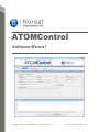
ATOMControl
Software Manual
Copyright © Norsat International Inc. All rights reserved.
Norsat P/N: INS001085_r1.0
NOTICE: Norsat International Inc. ("Norsat") assumes no responsibility for errors or
omissions that may appear in this publication. Norsat reserves the right to change this
publication at any time, without notice.
NORSAT ATOMControl – Software Manual. Copyright © 2014.
Norsat International Inc. All rights reserved.
All materials contained in this user guide are the property of Norsat International Inc.
except as noted here below:
All materials in this user guide are protected by United States and international copyright
laws. The compilation of all content in this user guide is the exclusive property of Norsat.
110 – 4020 Viking Way | Richmond | British Columbia | Canada V6V 2L4
[email protected] | Tel: +1.604.821.2800 | Toll Free: +1.800.644.4562
www.norsat.com
Printed in Canada
- 1 -
TABLE OF CONTENTS
PREFACE ........................................................................................................................................ 3
Purpose and Scope of the User Guide ............................................................................... 4
Audience ............................................................................................................................. 4
Revision History .................................................................................................................. 4
1
ATOMCONTROL BASICS ....................................................................................................... 5
Overview ............................................................................................................................. 6
Launching ATOMControl .................................................................................................... 7
ATOMControl User Interface .............................................................................................. 8
Initializing Communication .................................................................................................. 8
Deinitializing Communication ............................................................................................. 9
2
MONITORING DEVICE INFORMATION ................................................................................ 10
Monitoring Device Information .......................................................................................... 11
3
CONTROLLING ATOM DEVICES ......................................................................................... 14
Controlling the Mute State ................................................................................................ 15
Sending Custom Commands............................................................................................ 23
TABLE OF FIGURES
Figure 1: ATOMControl Start-Up Screen ........................................................................................ 7
Figure 2: The Device Info Tab ....................................................................................................... 11
Figure 3: Mute Tab Controls .......................................................................................................... 15
Figure 4: Mute State Logic ............................................................................................................ 16
Figure 5: Hardware-Based Muting Controls .................................................................................. 18
Figure 6: Fault-Based Muting Controls .......................................................................................... 20
Figure 7: Software-Based Muting Controls ................................................................................... 21
Figure 8: Mute State ...................................................................................................................... 22
Figure 9: The Custom Commands Tab ......................................................................................... 23
Figure 10: Command and Response Strings Showing <CR> and <LF> ...................................... 25
Figure 11: Command and Response Strings Without <CR> and <LF> ........................................ 25
TABLE OF TABLES
Table 1: Product Type Values ....................................................................................................... 12
Table 2: Detectable Faults ............................................................................................................. 12
Table 3: Number of Expected Power Modules for Each ATOM Device Type ............................... 13
Table 4: Hardware-Based Muting .................................................................................................. 17
Table 5: Fault-Based Muting ......................................................................................................... 19
- 2 -
Preface
- 3 -
Preface
Purpose and Scope of the User Guide
The user guide explains the usage of the Norsat ATOMControl monitor and control
application for ATOM Series Block UpConverters (BUCs) and Solid-State Power
Amplifiers (SSPAs).
This user guide is specifically written for the ATOMControl application. Additional
information can be found in the ATOM Series BUC or SSPA User Manual.
Audience
The guide will be of interest to the following personnel:
Field users
Systems administrators (or IT; Lifecycle/Sustainment Managers)
Revision History
Date
May 2014
Nature of Revision
Initial Release
Release
1.0
READ THE MANUAL BEFORE USING
THE ATOMControl APPLICATION
- 4 -
Preface
1 ATOMControl Basics
- 5 -
1 ATOMControl Basics
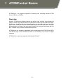
ATOMControl is a program designed for monitoring and controlling Norsat’s ATOM
Series of BUCs and SSPAs.
Overview
Norsat’s ATOMControl software features an intuitive User Interface that provides the
ability to monitor and control Norsat’s ATOM Series of Block Up-Converters and SolidState Power Amplifiers. Basic device information can be monitored along with fault,
temperature, and RF power data. ATOMControl also provides full control over an ATOM
Series device’s mute state, and gives users the ability to communicate directly with the
BUC or SSPA using a custom communication protocol.
ATOMControl is a stand-alone application that communicates with ATOM Series BUCs
and SSPAs using a serial RS-485 connection via a COM Port on a host PC or laptop
computer.
ATOMControl is currently supported on Windows® XP and 7.
- 6 -
1 ATOMControl Basics
Launching ATOMControl
ATOMControl should be launched like any other standard application: by double-clicking
on the application’s EXE file. ATOMControl does not require any Administrator-level
privileges to run, and can thus be run by any user on the host PC.
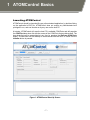
At startup, ATOMControl will scan the host PC’s available COM Ports and will populate
the COM Port drop-down list with the names of the COM Ports that are discovered. The
drop-down list can be repopulated at any time by pressing the Re-Scan COM Ports
button. ATOMControl will not attempt to communicate with the BUC or SSPA until the
Initialize button is pressed.
Figure 1: ATOMControl Start-Up Screen
- 7 -
1 ATOMControl Basics
ATOMControl User Interface
ATOMControl’s User Interface is made up of three main sections: the Configuration
section, the Controls section, and the Log Output section. Additionally, the application’s
version number is displayed at the top of the application window in the title bar.
The Configuration section provides controls that let the user configure the
communication settings that allow ATOMControl to communicate with an ATOM BUC or
SSPA. The user has the ability to select the COM Port that will be used for
communication, repopulate the drop-down list of available COM Ports, initialize the
communication interface, and deinitialize the communication interface.
The Controls section provides controls that facilitate the monitoring and control of an
ATOM Series BUC or SSPA. A tabbed interface provides controls related to Device
Information, Mute controls, and Custom Commands that can be sent to the BUC or
SSPA.
The Log Output section contains a text field that will display messages related to
ATOMControl operations performed on the ATOM BUC or SSPA. Any errors
encountered by the application will result in error messages being printed in this text
field. Status information may also be printed in the text field. Text may be copied from
this field so that it can be pasted into a text editor; the text field can also be cleared using
the Clear Log Output button.
Initializing Communication
Communication with the ATOM BUC or SSPA cannot be established unless the BUC or
SSPA is physically connected to the Host PC (or laptop) running ATOMControl. Since
most PCs and laptops lack an RS-485 serial port connection, it is recommended that a
4-Wire RS-485-to-RS-232 adapter be used to connect the ATOM device to the Host PC.
A 4-Wire RS-485-to-USB adapter may also be used to facilitate the connection.
The Host PC’s operating system should map the BUC or SSPA connection to a COM
Port that can be used by ATOMControl to communicate with the ATOM device.
ATOMControl will display the available COM Ports in the COM Port drop-down list in the
Configuration section of the User Interface. The list of available COM Ports can be
repopulated by pressing the Re-Scan COM Ports button. This allows the appropriate
COM Port to be selected even if the ATOM BUC or SSPA is connected to the Host PC
after the ATOMControl application has been launched.
Once a COM Port has been selected in the COM Port drop-down list, communication
with the BUC or SSPA can be established by pressing the Initialize button. ATOMControl
will automatically detect the type of device it is communicating with (BUC or SSPA, plus
the maximum output power of the device) and use this information to facilitate proper
- 8 -
1 ATOMControl Basics
communication with the ATOM BUC or SSPA. The controls in the Controls section of the
User Interface will also be enabled.
If communication cannot be established with the BUC or SSPA, an error message
explaining the problem will be printed in the text field in the Log Output section of the
User Interface. Successful communication will also be indicated in this text field. If
communication with the BUC or SSPA is successfully established, the COM Port dropdown list, the Re-Scan COM Ports button, and the Initialize button will be disabled and
the Deinitialize button will be enabled.
Deinitializing Communication
Deinitializing the ATOMControl communication interface halts all communication with the
BUC or SSPA, and allows the settings in the Configuration section of the User Interface
to be changed. The communication interface can be deinitialized by pressing the
Deinitialize button in the Configuration section of the User Interface. If the
communication interface is successfully deinitialized, the COM Port drop-down list, the
Re-Scan COM Ports button, and the Initialize button will be enabled and the
Deinitialize button will be disabled. A status message will also be printed in the text field
in the Log Output section of the User Interface. If the communication interface could not
be deinitialized, an error message will be printed in the text field in the Log Output
section of the User Interface.
ATOMControl has been configured to automatically deinitialize the communication
interface when the application is closed.
- 9 -
2 Monitoring Device Information
- 10 -
2 Monitoring Device Information
This chapter explains how to use ATOMControl to monitor identification,status, fault, and
temperature data for an ATOM Series BUC or SSPA.
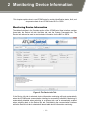
Monitoring Device Information
The tabbed interface in the Controls section of the ATOMControl User Interface contains
three tabs: the Device Info tab, the Mute tab, and the Custom Commands tab. The
Device Info tab can be used to monitor basic information for the BUC or SSPA.
Figure 2: The Device Info Tab
If the Device Info tab is selected, device information monitoring will begin automatically
when the ATOMControl communication interface is successfully initialized. Monitoring is
automatically disabled when switching to a different tab, and is automatically enabled
when switching back to the Device Info tab. Deinitializing the communication interface
while the Device Info tab is selected will also disable device information monitoring.
- 11 -
2 Monitoring Device Information
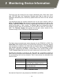
The Device Info tab contains five sets of data: Identification data, Status data, Faults
data, SAT-7200 data, and Temperature Readings data. Data for each set will be
populated automatically and continuously updated while the Device Info tab remains
selected.
The Identification data set contains information that can be used to identify a BUC or
SSPA. The Serial Number field will list the unique serial number for the device. The
Product Type field indicates the maximum output power and the device type; possible
values are provided in Table 1 below. The Device Type field indicates the type of
Distribution Board used in the ATOM device, and can be set to either SAT-7500 or SAT9000. The Firmware Version field provides the four-part version number for the
firmware running on the ATOM device’s Distribution Board.
Type of BUC
KU 25W BUC
KU 40W BUC
KU 50W BUC
KU 100W BUC
Type of SSPA
KU 25W SSPA
KU 40W SSPA
KU 50W SSPA
KU 100W SSPA
Table 1: Product Type Values
The Status data set contains basic status information for the ATOM BUC or SSPA. The
Fault Status field indicates whether any fault has been detected on the device; detailed
fault information is available in the Faults data set described below. The Temperature
field indicates the system temperature for the device. This is the temperature of Power
Module 8 for 100W BUCs and SSPAs, or Power Module 2 for all other ATOM devices.
The RF Forward Power field shows the current output power for the device in dBm.
Detailed fault information is provided in the Faults data set. A checkbox is shown for
each of the four faults that can be detected for a device. If the checkbox is checked, then
the corresponding fault has been detected. Table 2 below shows the detectable faults
and their cause:
Fault
Over Temperature
Power
PLL
Mute
Cause
The system temperature exceeds 90°C
The Voltage Monitor has detected that
one of the input voltages is too low.
At least one Phase Lock Loop (PLL)
Lock has been lost
The device has been muted
Table 2: Detectable Faults
Note that the Power fault is only detected on 100W BUCs and SSPAs.
- 12 -
2 Monitoring Device Information
Also note that the PLL Fault is only detected for BUCs, not SSPAs.
The SAT-7200 data set provides version information for the SAT-7200 Synthesizer
board used with ATOM BUCs. This information is only available for BUCs; SSPAs do not
use the SAT-7200 and thus do not provide any version information. The Hardware
Version field shows the hardware version for the SAT-7200 board, while the Firmware
Version field shows the version of the firmware running on the board.
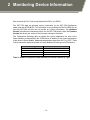
The Temperature Readings data set shows the current temperature for each of the
Power Modules contained within the ATOM device in addition to the current temperature
of the device’s Driver Module. Measured temperatures range from -40°C to 125°C. Table
3 below shows the expected number of Power Modules for each type of ATOM device:
Device Type
KU 25W BUC or SSPA
KU 40W BUC or SSPA
KU 50W BUC or SSPA
KU 100W BUC or SSPA
Number of Power Modules
2 + 1 Driver Module
4 + 1 Driver Module
4 + 1 Driver Module
8 + 1 Driver Module
Table 3: Number of Expected Power Modules for Each ATOM Device Type
- 13 -
3 Controlling ATOM Devices
- 14 -
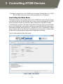
3 Controlling ATOM Devices
This chapter explains how to use ATOMControl to configure the Mute State of an ATOM
BUC or SSPA, and how to send custom commands to an ATOM device.
Controlling the Mute State
The tabbed interface in the Controls section of the ATOMControl User Interface contains
three tabs: the Device Info tab, the Mute tab, and the Custom Commands tab. The Mute
tab can be used to monitor and control the Mute configuration for the BUC or SSPA.
If the Mute tab is selected, then Mute Configuration monitoring will begin automatically
when the ATOMControl communication interface is successfully initialized. Monitoring is
automatically disabled when switching to a different tab, and is automatically enabled
when switching back to the Mute tab. Deinitializing the communication interface while
the Mute tab is selected will also disable Mute Configuration monitoring.
Figure 3 below shows the Mute tab controls:
Figure 3: Mute Tab Controls
- 15 -
3 Controlling ATOM Devices
An ATOM Series device’s Mute State is controlled by one hardware input signal, four
user-controllable software parameters, and three fault indicators. ATOMControl monitors
the values of all of these and displays them in the Mute Tab of the User Interface.
The signals are:
Mute Input:
The hardware input line corresponding to pin D of the MIL-C26482 control interface
Mute Invert:
Determines which value of the Mute Input line represents
Mute and which value represents Unmute
Mute Bias:
Determines the value of the Mute Input line if the hardware
input is left floating
Mute Command:
Software mute setting
Mute On Fault:
Indicates whether the device will be muted if a fault is
detected
Muting can thus be caused by three potential sources: a hardware-based mute triggered
through the Mute Input hardware signal, fault-based muting triggered by one of three
faults, and software-based muting triggered using the Mute Command parameter.
Software-based muting will override both fault-based muting and hardware-based
muting. Fault-based muting will also override hardware-based muting.
The hardware signal, four software parameters, and three faults interact with each other
to produce the overall Mute State as shown in Figure 4 below:
Figure 4: Mute State Logic
- 16 -
3 Controlling ATOM Devices
Hardware-Based Muting
Hardware-based muting is controlled by three values: the Mute Input hardware line, the
Mute Invert software parameter, and the Mute Bias software parameter. The Mute Input
line allows external devices to control whether the ATOM Series BUC or SSPA is muted
or unmuted. The signal value required to mute or unmute the ATOM device is
determined by the value of the Mute Invert parameter. If Mute Invert is 0, then setting
Mute Input to 0V will unmute the device and setting Mute Input to 5V will mute the
device. If Mute Invert is 1, then setting Mute Input to 0V will mute the device and setting
Mute Input to 5V will unmute the device.
The Mute Bias signal controls the value of the Mute Input hardware line if the hardware
line is left floating. If Mute Bias is 0, then a floating Mute Input line will be pulled down to
0V. If Mute Bias is 1, then a floating Mute Input line will be pulled up to 5V.
By default, both Mute Bias and Mute Invert are set to 0.
The hardware-based muting parameter interactions are summarized in Table 4 below:
Mute Input
Voltage
0V
0V
0V
0V
5V
5V
5V
5V
Floating
Floating
Floating
Floating
Mute Input
Logical Value
0
0
0
0
1
1
1
1
Z
Z
Z
Z
Mute Invert
Logical Value
0
0
1
1
0
0
1
1
0
0
1
1
Mute Bias
Logical Value
0
1
0
1
0
1
0
1
0
1
0
1
Hardware
Mute Result
Unmuted
Unmuted
Muted
Muted
Muted
Muted
Unmuted
Unmuted
Unmuted
Muted
Muted
Unmuted
Table 4: Hardware-Based Muting
ATOMControl shows all of the values relevant to hardware-based muting in the top-left
groupbox in the Mute tab in the Controls section of the User Interface. The logical value
of the Mute Input line, the Mute Invert parameter, and the Mute Bias parameter are all
displayed along with buttons that allow the Mute Invert and Mute Bias signal values to be
toggled between 0 and 1. Figure 5 below shows the hardware-based muting controls:
- 17 -
3 Controlling ATOM Devices
Figure 5: Hardware-Based Muting Controls
The value represented in the Mute Input field depends on the type of device that
ATOMControl is monitoring. If the device is a 25W, 40W, or 50W BUC or SSPA, then the
Mute Input field will display the value of the Mute Input hardware line. A value of 0
represents 0V, and a value of 1 represents 5V. For 100W BUCs and SSPAs, the value
shown will represent the overall Mute State, with 0 indicating that the device is unmuted
and 1 indicating that the device is muted.
- 18 -
3 Controlling ATOM Devices
Fault-Based Muting
Fault-based muting automatically mutes the device if one of three faults is detected on
the ATOM Series BUC or SSPA. A PLL Fault, a Power Fault, and an Over Temperature
Fault can all trigger automatic muting. These faults will only mute the device, however, if
the Mute On Fault software parameter is set to 1. If Mute On Fault is set to 0 then the
device will not be automatically muted if a fault is detected on the device. By default, the
Mute On Fault parameter is set to 1.
Table 5 below shows the interaction of the fault-based muting signals:
Mute On Fault
0
0
0
0
0
0
0
0
1
1
1
1
1
1
1
1
Power Fault
0
0
0
0
1
1
1
1
0
0
0
0
1
1
1
1
OverTemp Fault
0
0
1
1
0
0
1
1
0
0
1
1
0
0
1
1
PLL Fault
0
1
0
1
0
1
0
1
0
1
0
1
0
1
0
1
Fault Mute Result
Unmuted
Unmuted
Unmuted
Unmuted
Unmuted
Unmuted
Unmuted
Unmuted
Unmuted
Muted
Muted
Muted
Muted
Muted
Muted
Muted
Table 5: Fault-Based Muting
ATOMControl shows all of the values relevant to fault-based muting in the top-right
groupbox in the Mute tab in the Controls section of the User Interface. The value of the
Mute On Fault parameter is displayed along with a button that allows the Mute On Fault
value to be toggled between 0 and 1. Additionally, the groupbox contains three read-only
checkboxes that indicate whether each of the three mute-inducing faults has been
detected. Figure 6 below shows the hardware-based muting controls:
- 19 -
3 Controlling ATOM Devices
Figure 6: Fault-Based Muting Controls
- 20 -
3 Controlling ATOM Devices
Software-Based Muting
Software-based muting is controlled by a single parameter that overrides all other muting
controls: the Mute Command parameter. If Mute Command is set to 1 then the ATOM
Series device will be muted. If the Mute Command signal is set to 0 then the device will
be unmuted (assuming it is not muted by hardware or by faults). By default, the Mute
Command parameter is set to 0.
ATOMControl shows all of the values relevant to software-based muting in the bottomleft groupbox in the Mute tab in the Controls section of the User Interface. The value of
the Mute Command parameter is displayed along with a button that allows the Mute
Command value to be toggled between 0 and 1. Figure 7 below shows the softwarebased muting controls:
Figure 7: Software-Based Muting Controls
- 21 -
3 Controlling ATOM Devices
Unmuting the Device
ATOM Series devices are unmuted only if nothing is causing them to be muted. The
parameters for hardware-based muting, fault-based muting, and software-based muting
must all be in a state that does not cause the BUC or SSPA to be muted in order for the
device to be in an unmuted state. ATOMControl displays the overall Mute State below
the Software-Based muting groupbox in the Mute tab in the Controls section of the User
Interface as shown in Figure 8 below:
Figure 8: Mute State
- 22 -
3 Controlling ATOM Devices
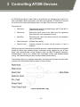
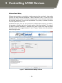
Sending Custom Commands
The tabbed interface in the Controls section of the ATOMControl User Interface contains
three tabs: the Device Info tab, the Mute tab, and the Custom Commands tab. The
Custom Commands tab can be used to communicate with the ATOM BUC or SSPA
directly using a series of command strings that follow the ATOM Communication
Protocol.
Figure 9: The Custom Commands Tab
ATOM Series BUCs and SSPAs are controlled using character-based command strings
sent over a serial interface. ATOMControl provides users with the ability to send
command strings to an ATOM Series device and to see the corresponding response
string received from the device. A single response string will be generated for all
commands sent to the device, but improperly-formatted or invalid command strings will
produce error response strings. Response strings are typically received immediately
- 23 -
3 Controlling ATOM Devices
after sending the command string, though some response strings are received only after
a short delay.
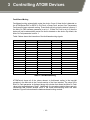
All command strings follow the same basic format: a Command Name, followed by zero
or more pairs of Command Parameters and Values, followed by a terminating Carriage
Return character. Sample commands include:
getident<CR>
setmute cmd 1<CR>
setmute value 0<CR>
All response strings also follow a common format: a Carriage Return character and a
Line Feed character at the start of the response, followed by a status string, followed by
zero or more pairs of Response Parameters and values, followed by a terminating
Carriage Return character and Line Feed character. Sample response strings (and the
commands that generated them) are as follows:
getstatus<CR>
<CR><LF>ok fault 0x0 fwdpwr +17.3 revpwr -15.8 temp 42<CR><LF>
setmute cmd 1<CR>
<CR><LF>ok<CR><LF>
bad command<CR>
<CR><LF>err "Invalid Command"<CR><LF>
Please consult the ATOM device’s Operator Manual for more details concerning the
command strings that can be sent down and the expected corresponding response
strings.
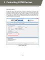
ATOMControl provides two sets of controls that can be used to send command strings to
an ATOM Series BUC or SSPA. The Send a Single Command text field allows the user
to type in a single command string to be sent to the device. Pressing the Enter key while
in this field will send the contents of the field to the device along with a terminating
Carriage Return character. Pressing the Up or Down Arrow keys while in this field will
cycle backwards or forwards through the history of previously-sent command strings.
Multiple commands can be sent one after the other using the Send Multiple
Commands multi-line text field. Commands may be typed into this field, copied-andpasted into this field, or loaded into the field from a text file using the Load Commands
From File button. All text can be removed from the field using the Clear Commands
button. Pressing the Execute Commands button will send each non-blank line in the
field down to the device, automatically adding a terminating Carriage Return character to
each command string.
- 24 -
3 Controlling ATOM Devices
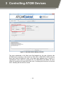
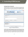
Command strings that are sent to an ATOM BUC or SSPA will be displayed in the Log
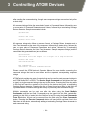
Output text field, as will the corresponding response string. If the Show <CR> and <LF>
in the Log Output checkbox is checked, then both the command string and the
response string will show the Carriage Return and Line Feed characters used in the
ATOM Communication Protocol. If the checkbox is unchecked, then the Carriage Return
and Line Feed characters will be stripped out of the command and response strings,
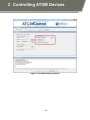
leaving only the content of the outgoing or incoming messages. Figure 10 and Figure 11
show sample command and response strings with and without the Carriage Return and
Line Feed characters displayed:
Figure 10: Command and Response Strings Showing <CR> and <LF>
Figure 11: Command and Response Strings Without <CR> and <LF>
- 25 -