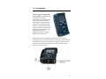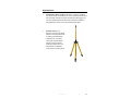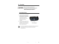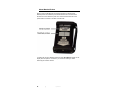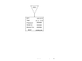
1
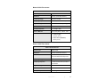
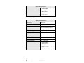
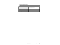
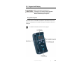
HI-2200
RF Survey Meter
User Manual
ETS-Lindgren L.P. reserves the right to make changes to any product described
herein in order to improve function, design, or for any other reason. Nothing
contained herein shall constitute ETS-Lindgren L.P. assuming any liability
whatsoever arising out of the application or use of any product or circuit
described herein. ETS-Lindgren L.P. does not convey any license under its
patent rights or the rights of others.
© Copyright 2003–2009 by ETS-Lindgren L.P. All Rights Reserved. No part
of this document may be copied by any means without written permission
from ETS-Lindgren L.P.
Trademarks used in this document: The ETS-Lindgren logo and ProbeView are
trademarks of ETS-Lindgren L.P.; Microsoft and Windows are registered
trademarks of Microsoft Corporation in the United States and/or other countries.
Revision Record | HI-2200, RF Survey Meter, Manual | Part #H-600095, Rev. D
Revision
Description
Date
A
Initial Release
December, 2003
B
Update Application section and
April, 2007
overall style
C
Update Model H210 H-Field Probe
September, 2008
specifications; rebrand
D
Updated dynamic range for
Model C300 E-Field Probe
ii
|
June, 2009
Table of Contents
Notes, Cautions, and Warnings .............................................. vii
1.0 Introduction .......................................................................... 9
Control / Meter Module Features ................................................................. 10
Harness ....................................................................................................... 10
Standard Configuration ................................................................................ 10
Optional Items .............................................................................................. 11
ETS-Lindgren Product Information Bulletin ................................................. 12
2.0 Maintenance ....................................................................... 13
Battery Replacement ................................................................................... 13
Annual Calibration ....................................................................................... 13
Replacement and Optional Parts ................................................................. 14
Service Procedures ..................................................................................... 14
3.0 Specifications..................................................................... 15
Meter Specifications .................................................................................... 15
Probe Specifications .................................................................................... 15
Model E100 E-Field Probe................................................................... 15
Model H200 H-Field Probe .................................................................. 16
Model H210 H-Field probe................................................................... 17
Model C300 E-Field Probe .................................................................. 17
Model C310 E-Field Probe .................................................................. 18
Physical Specifications ................................................................................ 19
4.0 Assembly and Installation ................................................ 21
Installing the Batteries ................................................................................. 21
5.0 Keypad and Display ........................................................... 23
Keypad Description ...................................................................................... 23
Screens Description ..................................................................................... 25
Monitoring and Top Level Navigation Screen ...................................... 25
6.0 Operation ............................................................................ 27
Connecting the Probe .................................................................................. 27
About Matched Probes ................................................................................ 28
Powering Up ................................................................................................ 29
|
iii
Possible Error Messages at Start Up................................................... 29
Probe Units .................................................................................................. 29
Units for the E-Field Probe .................................................................. 29
Units for the H-Field Probe .................................................................. 30
Units for the Conformal Field Probes................................................... 30
Setup ........................................................................................................... 30
Log Mode ............................................................................................. 30
Alarm Point .......................................................................................... 31
Audio.................................................................................................... 31
Graph Style .......................................................................................... 32
Avg Window ......................................................................................... 32
Display Mode ....................................................................................... 33
Number Digits ...................................................................................... 34
AVG Mode ........................................................................................... 34
Data ............................................................................................................. 34
Log View .............................................................................................. 34
Log Upload .......................................................................................... 35
Log Delete ........................................................................................... 35
Miscellaneous .............................................................................................. 36
Reset ................................................................................................... 36
Download ............................................................................................. 36
7.0 Application ......................................................................... 37
Begin Logging .............................................................................................. 37
Probe Support Structures ............................................................................ 38
Averaging ..................................................................................................... 38
8.0 Upload Utility ...................................................................... 41
Install Upload Utility ..................................................................................... 41
Start Upload Utility ....................................................................................... 41
Upload Data ................................................................................................. 42
View Data .................................................................................................... 42
9.0 Download Utility ................................................................. 43
Install Download Utility ................................................................................. 43
Start Download Utility .................................................................................. 43
Download the File ........................................................................................ 44
Appendix A: Warranty ............................................................. 45
iv
|
Appendix B: Menu Tree ........................................................... 47
Appendix C: EC Declaration of Conformity .......................... 53
|
v
This page intentionally left blank.
vi
|
Notes, Cautions, and Warnings
Note: Denotes helpful information intended to
provide tips for better use of the product.
Caution: Denotes a hazard. Failure to follow
instructions could result in minor personal injury
and/or property damage. Included text gives proper
procedures.
Warning: Denotes a hazard. Failure to follow
instructions could result in SEVERE personal injury
and/or property damage. Included text gives proper
procedures.
See the ETS-Lindgren Product Information Bulletin for safety,
regulatory, and other product marking information.
|
vii
This page intentionally left blank.
viii |
1.0 Introduction
The ETS-Lindgren Holaday HI-2200
RF Survey Meter is designed for basic
radio frequency (RF) safety
measurements. The survey meter is a
compact measurement system with
interchangeable probes that provides
testing flexibility. Applications include
broadcast, commercial radio, television,
mobile communication, and health care
facilities. Electric and magnetic probes
are sold separately; see the
specifications section for a detailed
description of available probes.
The front panel of the HI-2200 includes an LCD display and a keypad; for a
description of the keys, see Keypad Description on page 23. A probe connection
is located at the top of the unit. At the bottom of the unit is a serial I/O connector
configured as a mini DIN, and a receptacle for mounting the unit on a tripod,
dielectric handle, or the harness.
Introduction
|
9
Control / Meter Module Features
•
Data logging capability
•
Interchangeable field probes
•
Easy to use space and temporal averaging
•
Lightweight, hand-held design
•
Large graphical display
•
Adjustable alarm threshold
•
User selectable meter units
•
RS-232 data interface
•
Greater than 20 hour battery life for four, AA, replaceable alkaline
batteries
•
Reversible hand strap for right or left hand use
Harness
The HI-2200 harness is designed to assist in carrying the unit in the field. The
purpose of the harness is to provide hands-free movement. It is not intended to
be a climbing harness. Above ground level, use proper personal safety
equipment while climbing.
Standard Configuration
10
•
RF Survey Meter
•
RS-232 Cable, Mini-DIN to D89
•
Upload/Download Software
•
Harness
•
Carrying Case
•
AA Alkaline Batteries (4)
|
Introduction
Optional Items
•
H-651020 Fiber Optic Link Kit—ProbeView II™ software combined
with the Fiber Optic Link Kit allows the user to optically link the HI-2200
with a personal computer for remote monitoring and data logging. The
use of the optical interface and fiber cable reduces the possibility of
field disturbances as seen when using traditional wire cables.
•
H-491009 Tripod—This
Dielectric Tripod is the preferred
method for mounting field probes
for making unperturbed field
measurements. It includes a
1/4–20 UNC threaded stud for
mounting any ETS-Lindgren
probe with a tripod mount. It is
designed with an adjustable
center post and a rotating mount.
Introduction
|
11
ETS-Lindgren Product Information Bulletin
See the ETS-Lindgren Product Information Bulletin included with your shipment
for the following:
12
•
Warranty information
•
Safety, regulatory, and other product marking information
•
Steps to receive your shipment
•
Steps to return a component for service
•
ETS-Lindgren calibration service
•
ETS-Lindgren contact information
|
Introduction
2.0 Maintenance
Before performing any maintenance, follow
the safety information in the ETS-Lindgren
Product Information Bulletin included with
your shipment.
Maintenance of the HI-2200 is limited to
external components such as cables or
connectors.
If you have any questions concerning
WARRANTY
maintenance, contact ETS-Lindgren
Customer Service.
Battery Replacement
The HI-2200 requires four AA batteries. See Specifications on
page 15 for additional battery specifications.
If the HI-2200 RF Survey Meter fails to power on, the batteries may be depleted.
To replace the batteries, follow the steps in Installing the Batteries on page 21 to
remove the battery tray from the HI-2200 and install new batteries.
Annual Calibration
See the Product Information Bulletin included with your shipment for information
on ETS-Lindgren calibration services.
Maintenance
|
13
Replacement and Optional Parts
Following are the part numbers for ordering replacement or optional parts for the
HI-2200.
Part Description
Part Number
RF Survey Meter
HI-2200
RS-232 Cable, Mini-DIN to D89
H-220110
Upload/Download Software
H-491196
Harness
H-470588
Carrying Case
H-491243
AA Alkaline Batteries (4)
400032
Fiber Optic Link Kit
H-651020
Tripod
H-491009
Service Procedures
For the steps to return a system or system component to ETS-Lindgren for
service, see the Product Information Bulletin included with your shipment.
14
|
Maintenance
3.0 Specifications
Meter Specifications
Internal Memory:
>65,000 data points
User Selectable Units
V/m, μW/cm , mW/cm , W/m A/m,
(Probe Dependent):
mA/m
Battery:
Four AA
2
2
2
(1.2–1.5 V Nominal Alkaline or
Nickel-Metal Hydride or
Nickel-Cadmium)
Operating Life:
Approximately 20 hours
(with new alkaline batteries)
o
o
Operating Temperature:
-10 C to 50 C
Connector:
RS-232 I/O serial interface six-pin
mini DIN
Probe Specifications
Probes must be calibrated or matched prior to using them with the
HI-2200. For more information, see Matched Probes on page 28.
The following tables represent probes that are designed to be used with the
HI-2200 RF Survey Meter.
MODEL E100 E-FIELD PROBE
Model E100 E-Field Probe
Sensor Type:
Electric Field
Detection:
Isotropic (Total Field Indication)
Frequency Range:
100 kHz – 5 GHz
Frequency Response:
± 1 dB (1 MHz to 4 GHz)
Dynamic Range:
0.3 V/m to 800 V/m (Single Range)
Specifications
|
15
Model E100 E-Field Probe
Overload Withstand:
>1200 V/m
Isotropic Response:
± 0.7 dB @ 400 MHz
Units of Measure:
V/m, µW/cm mW/cm , W/m
E-Field Probe Dimension:
• Overall Length:
2,
2
2
260 mm (10.3 in)
• Sensor Cover:
60 mm x 71.1 mm
2.4 in x 2.8 in
MODEL H200 H-FIELD PROBE
Model H200 H-Field Probe
Sensor Type:
Magnetic Field
Detection:
Isotropic (Total Field Indication)
Frequency Range:
5 MHz to 300 MHz
Frequency Response:
± 1 dB (10 MHz to 100 MHz)
± 2.5 dB (5 MHz to 300 MHz)
Dynamic Range:
30 mA/m – 10 A/m (Single Range)
Overload Withstand:
20 A/m
Isotropic Response:
± 0.7 dB @ 100 MHz
Units of Measure:
A/m, mA/m µW/cm mW/cm , W/m
E-Field Probe Dimension:
• Overall Length:
2,
2
260 mm (10.3 in)
• Sensor Cover (Diameter):
60 mm (2.4 in)
16
|
Specifications
2
MODEL H210 H-FIELD PROBE
Model H210 H-Field Probe
Sensor Type:
Magnetic Field
Detection:
Isotropic (Total Field Indication)
Frequency Range:
300 kHz to 30 MHz
Frequency Response:
± 0.8 dB (300 kHz to 30 MHz)
Dynamic Range:
0.3 A/m to 30 A/m (Single Range)
Overload Withstand:
60 A/m
Isotropic Response:
± 0.7 dB @ 27 MHz
Units of Measure:
A/m, mA/m µW/cm mW/cm , W/m
E-Field Probe Dimension:
• Overall Length:
2,
2
2
260 mm (10.3 in)
• Sensor Cover (Diameter):
60 mm (2.4 in)
MODEL C300 E-FIELD PROBE
Model C300 E-Field Probe
Sensor Type:
Electric Field
Detection:
Isotropic (Total Field Indication)
Conformance:
FCC radio Frequency Exposure Limits
Occupational/Controlled Exposures
Frequency Range:
100 kHz to 8 GHz
Frequency Response:
± 3 dB to actual limits as specified in
the standard
Dynamic Range:
<1%–999% of FCC Standard
Resolution:
Limited to 1%
Isotropic Response:
± 0.7 dB @ 400 MHz
Specifications
|
17
Model C300 E-Field Probe
E-Field Probe Dimension:
• Overall Length:
260 mm (10.3 in)
• Sensor Cover:
60 mm x 71.1 mm
(2.4 in x 2.8 in)
MODEL C310 E-FIELD PROBE
Model C310 E-Field Probe
Sensor Type:
Electric Field
Detection:
Isotropic (Total Field Indication)
Conformance:
International Commission on
Non-Ionizing Radiation Protection
(ICNIRP) Occupational levels
Frequency Range:
100 kHz to 8 GHz
Frequency Response:
± 3 dB to actual limits as specified in
the standard
Dynamic Range:
<1%–999% of ICNIRP Standard
Resolution:
Limited to 1%
Isotropic Response:
± 0.7 dB @ 400 MHz
E-Field Probe Dimension:
• Overall Length:
260 mm (10.3 in)
• Sensor Cover:
60 mm x 71.1 mm
(2.4 in x 2.8 in)
18
|
Specifications
Physical Specifications
Control / Meter Module:
85 mm x 160 mm x 30 mm
3.3 in x 6.3 in x 1.2 in
Weight:
0.64 kg (0.29 lb)
Mounting:
1/4–20 UNC Internal Thread
Specifications
|
19
This page intentionally left blank.
20
|
Specifications
4.0 Assembly and Installation
Before connecting any components, follow the
safety information in the ETS-Lindgren
Product Information Bulletin included with your
shipment.
Installing the Batteries
The batteries for the HI-2200 RF Survey Meter are shipped uninstalled. To install
the batteries, retrieve the battery tray with the four AA batteries from the HI-2200
carrying case, and then follow these instructions:
1.
Remove the end cap and bottom panel by unscrewing the four Phillips
head screws.
2.
Remove the washers, the protective end cap, and the metal cover.
3.
Slide the battery tray, including the batteries, into the meter case so
the posts align with the contacts inside.
4.
Replace the bottom panel and end cap.
5.
With a washer around each screw, re-insert the screws to secure the
bottom panel and end cap into place.
Assembly and Installation
|
21
This page intentionally left blank.
22
|
Assembly and Installation
5.0 Keypad and Display
Before connecting any components or
operating the unit, follow the safety information
in the ETS-Lindgren Product Information
Bulletin included with your shipment.
Keypad Description
The front panel of the HI-2200 RF Survey Meter is comprised of two basic user
areas: the LCD display and the keypad. Following is a description of the keys on
the keypad.
For additional information, see Menu Tree on page 47.
Keypad and Display
|
23
Key
Description
POWER
Turns the unit on and off.
Function keys (4)
• The four function keys select submenus displayed
at the bottom of each screen.
• These keys are also used for setting specific
values.
• The function of each key will change as different
screens are viewed.
BACK
• Navigates back one menu level.
• This key also functions as an Enter key after
settings have been selected or changed.
• If BACK is pressed when in the monitoring screen,
the MAX and AVG values displayed on the
monitoring screen will be reset. This may also be
accomplished by holding the key down for
approximately four seconds.
• When viewing a data file, press BACK to return
the display to the main menu.
LOG keys (2)
• The two LOG keys each perform the same
function. They are positioned on the left and right
to accommodate left-handed and right-handed
use.
• The default logging function is single point logging
(one data point is logged or saved with each log
key operation).
• Other logging functions are explained in Setup on
page 30.
24
|
Keypad and Display
Screens Description
When the RF Survey Meter is initially turned on, the screen displays contact
information for ETS-Lindgren. In addition to the contact information the model
number and most recent software revision date are provided. After the initial
screen, the monitoring screen is displayed. The following sections explain the
different monitoring and logging screens.
For additional information, see Menu Tree on page 47.
MONITORING AND TOP LEVEL NAVIGATION SCREEN
1 Linear/Logarithmic bar graph
6 Current field value and units selected
2 Data file number
7 Function keys; see
Keypad Description on page 23 for a
description of functions keys
3 Data point number
8 RDG indicates that the main number
displayed is the current reading
4 Elapsed time since the
9 Maximum field value measured
beginning of the new log file
5 Average field value
Keypad and Display
|
25
The monitoring screen displays the current field reading, the maximum value, an
average of the values, the length of time the meter has been on, or the time since
the beginning of a new log file, the log file and data point number, and the four
options available to the function keys.
In the default state data is not recorded until the log key is pressed.
The options available to the four function keys are displayed at the bottom of the
screen.
The main area of the screen give details regarding the present field reading
(RDG) in large digits, along with the units of measure currently selected. When
no probes are attached this area will display NO PROBE. When a probe that is
not calibrated for the meter is attached, this area will display NO CALIB.
26
|
Keypad and Display
6.0 Operation
Before connecting any components or
operating the unit, follow the safety information
in the ETS-Lindgren Product Information
Bulletin included with your shipment.
Connecting the Probe
1. Connect the probe to the receptacle
located at the top of the HI-2200
RF Survey Meter. To avoid damage
to the connection, align the
indexing marks and pins on the
probe connector with the
receptacle.
2. Turn the connector sleeve until it is
finger tight to secure the probe into
place. Do not use any mechanical
means to tighten the probe.
Do not connect a probe to the HI-2200 while the meter is powered on.
The HI-2200 must be powered off before it will recognize a
newly-added probe.
Operation
|
27
About Matched Probes
When a probe is calibrated with the HI-2200 it becomes a matched probe.
Matched probes are indicated by the barcode labels found on the back of the
HI-2200 and on the shaft of the probe. The number below the barcode on the
probe matches a number on the back of the HI-2200.
If a probe has not been calibrated with the HI-2200, NO CALIB will appear on the
display while the probe is connected. If you receive this message, contact
ETS-Lindgren Customer Service.
28
|
Operation
Powering Up
Press POWER on the HI-2200. The start up screen will display briefly, followed
by the initial monitoring screen.
POSSIBLE ERROR MESSAGES AT START UP
Error Message
Description
No Probe
A probe is not connected to the HI-2200.
No Calib
The attached probe is not matched to the HI-2200.
Low Field
The probe indication is less than 0.3 V/m.
If a probe is attached while the HI-2200 is powered on, turn the meter
off and then on again to recognize the probe.
Probe Units
From the monitoring screen press the function key under Units to step through
the options for the attached probe.
UNITS FOR THE E-FIELD PROBE
Field Intensity:
V/m—Volts per meter
2
• μW/cm —Microwatts per
square centimeter
2
• mW/cm —Milliwatts per
Plane Wave Equivalent
Power Density:
square centimeter
2
• W/m —Watts per square
meter
Operation
|
29
UNITS FOR THE H-FIELD PROBE
• A/m—Amps per meter
Field Intensity:
• mA/m—Milliamps per meter
2
Plane Wave Equivalent
mW/cm —Milliwatts per square
Power Density:
centimeter
UNITS FOR THE CONFORMAL FIELD PROBES
The ETS-Lindgren Conformal Field Probes provide a measure of field intensity
tailored to conform to the industry standard. The sum of the resulting
contributions is displayed as a percent of the allowable exposure limits.
Logged data will indicate the unit of measure that was selected during logging
Setup
Under the Setup menu there are many options that will assist in configuring the
attached probe. The options are explained here; for additional information, see
Menu Tree on page 47.
LOG MODE
Log Mode allows the selection of single point, continuous, or spatial logging.
•
Single point logging will collect one data point each time the log key is
pressed (not more than one point per second).
•
Continuous logging will log one data point per second beginning when
the log key is pressed and ending when the log key is pressed again.
•
Spatial averaging mode changes the default settings so the meter is
set to collect a running average. The display mode is updated so the
primary number displayed is the AVG value. When spatial averaging is
activated a new log file must be created for each set of data collected.
The append feature is not available in this mode. The meter logs one
data point per second beginning when the log key is pressed and
ending when log is pressed again.
30
|
Operation
In spatial averaging, a series of measurements are taken during a
relatively short period of time (usually not more than two to three
minutes). At the end of the period, the average value is the answer.
The measurement is used to monitor compliance with standards,
based on the whole-body average maximum permissible exposures
(MPE). The average field is measured over the space occupied by the
subject’s body.
For more information about averaging see Averaging on page 38.
ALARM POINT
Alarm Point allows the user to set a field level above which an alarm will
indicate/sound. The range is 0.00 to 1000 units. Audio must be set to Alarm for
an audible tone to sound when the alarm level is reached. If the alarm level is set
higher than the range of the probe, the alarm will not indicate/sound. Setting the
alarm level to 0.00 will turn the alarm off.
AUDIO
Audio is an audio annunciator that is provided to signal various functions on the
HI-2200. Options include None, Alarm, Cadence, and Both.
•
None turns off all sounds excluding the startup tone.
•
Alarm causes the unit to emit a tone when the alarm level set under
the Alarm Point option is exceeded.
•
Cadence enables a pulsing tone to assist in measuring consistently
over a distance. This tone sounds every second during logging in
continuous or spatial log mode.
•
Both enables the alarm point tone and the cadence tone at the same
time. In addition to the pulse tone, a continuous tone will sound when
the alarm level is reached
Operation
|
31
GRAPH STYLE
Graph Style enables the style of graph that will be displayed at the top of the
screen.
Linear Graph Scale
•
Linear produces a graph displayed that is directly proportional to the
measured field intensity. The display will indicate from 0% to 100% of
the full scale.
Log Graph Scale (flip)
•
Log produces a graph that is proportional to the log of the measured
field intensity from 10% to 100%.
When in spatial mode, SPATIAL AVG text replaces the graph.
AVG WINDOW
Avg Window allows for the selection of the time interval used to calculate the
moving average. Moving average is an average of readings taken over a
selected period of time. Moving average readings assume that exposure has
been zero until the beginning of the averaging period. For example, to obtain a
true three minute moving average in an existing field, the meter must log data for
at least three minutes
Average Intervals
Description
3 MIN MOV
3 minute moving average
6 MIN MOV
6 minute moving average
12 MIN MOV
12 minute moving average
30 MIN MOV
30 minute moving average
A running average of all the data points
RUNNING
32
collected
|
Operation
Theoretical Sample of 6-Minute Average
DISPLAY MODE
Display Mode selects the value that will be displayed as the primary number on
the LCD display.
Values
Description
RDG (Reading)
The current field reading.
Displays the maximum value measured since
MAX (Maximum)
the settings were changed or the MAX was
reset.
An average of the measured values. The
AVG (Average)
AVG SIZE setting allows for the selection of
the time interval used to calculate a moving
average.
Operation
|
33
Theoretical Sample of Charging Field
NUMBER DIGITS
Number Digits allows the selection of the number of digits, either three or four,
to be displayed.
AVG MODE
AVG Mode allows the selection between MEAN and RMS (root mean square).
•
Mean is the average of the observed values from the beginning of the
averaging interval.
•
RMS refers to the square root of the mean of the squared value of a
function. The RMS average field intensity value is proportional to the
power density of the field. When logging in power density units, the
RMS and mean values are equal.
For more information on averaging see Averaging on page 38.
Data
Options under the data menu include: Log View, Log Upload, and Log Delete.
LOG VIEW
Log View displays the logged data files stored in the unit.
34
|
Operation
1.
Navigate to the Log View menu option and select Yes.
2.
Select a file to view using the UP ARROW and DOWN ARROW keys.
3.
With the file number you wish to view displayed on the screen, press
the key below the View option to begin viewing the file.
4.
The arrow options that appear display one data point at a time when
one of the right/left keys below a single arrow is pressed.
5.
To view the entire data file press one of the keys below the double
arrows.
6.
Press a double arrow key to sequence through the entire file.
7.
Press the Back key to exit.
LOG UPLOAD
See Upload Utility on page 41 for information.
LOG DELETE
A deleted file cannot be recovered.
Log Delete removes files from memory in the meter. When Yes is selected
under the Log Delete option, a new screen will appear that allows the selection of
files to be removed.
1.
Use the UP ARROW and DOWN ARROW keys to navigate to the file
number to be deleted.
2.
Press the key under the Mark option to select the file to be deleted,
and then press the key under Delete.
You may mark multiple files then press Delete once to remove the
files.
To delete all log files, press the Delete key at the Select Files. At the
message Delete all files are you sure, press the key under Yes to
delete the files. Press the Back key to avoid deleting all of the files.
Operation
|
35
Miscellaneous
The MISC screen shows battery voltage, temperature, probe meter serial
number, probe serial number, and meter serial number. From this screen you
may also Reset and Download.
•
Probe Meter Serial Number—Serial number of the meter that the probe
was calibrated for.
•
Probe Serial Number—Serial number of the probe.
•
Meter Serial Number—Serial number of the HI-2200.
RESET
Reset will return the meter to its default state, and all stored data will be cleared.
Use this option carefully.
DOWNLOAD
Download is used when new firmware needs to be added to the probe. See
Download Utility on page 43 for information.
36
|
Operation
7.0 Application
Begin Logging
From the main navigational menu use the UNITS key to select the unit of
measure to use for logging. The unit of measure cannot be changed while
logging is in progress.
•
Verify that all settings are configured according to your test plan. On
the Setup menu, select Log Mode, and then select Single,
Continuous, or Spatial (see Setup on page 30 for more information).
Selecting any of these settings will create a new log file.
•
Data points must be saved or appended into a file before another new
log file can be created.
•
Press the Back key to exit the Setup menu.
•
Press one of the LOG keys to begin logging.
•
For single point logging: The LOG key must be operated to save or log
each data point.
•
For continuous logging: Press the LOG key once to begin logging and
again to stop the logging process
Once logging is complete, the available options are to Save, Append, Delete, or
View the data logged
•
Save—The logged data will be saved in the new file and the function
key menu will become available at the bottom of the screen.
•
Append—The most recent data is added to the same (current) file.
This option is not available in Spatial Log mode.
•
Delete—Removes the current data points from memory
•
View—Allows the data to be seen before choosing to save or delete.
Application
|
37
Probe Support Structures
It is very important to keep conductive objects away from the HI-2200 RF Survey
Meter while measuring. Any conductive objects in the proximity of the probe may
distort the field and compromise measurement accuracy. If the application
requires measurements from a fixed position, always mount the probe on a
non-metallic platform using non-metallic screws. The optional ETS-Lindgren
Holaday H-491009 Tripod provides an adjustable, dielectric support for the
H-2200. See Optional Items on page 11 for more information.
Averaging
When evaluating electromagnetic field measurements, proper averaging of data
is an important part of the measurement process. Two aspects of averaging
when measuring electromagnetic fields should be considered.
First, how is the data actually averaged? In simple or LINEAR averaging, each
value of a group of field intensity readings is summed and the sum divided by the
total number of readings in the group. This type of averaging is more typically
used for lower frequency measurements (below about 100 kHz) when a safety
guideline or standard allows averaging.
At higher frequencies (typically above about 100 kHz), the primary metric of
interest is the energy absorption into the body. To most accurately define these
exposures, it is necessary that averaging be proportional to power density (more
accurately plane-wave-power-density) which is proportional to the square of the
field intensity (field-strength-units-squared). With the HI-2200, this type of
averaging is described as RMS (root mean square) averaging. In this mode,
each of the individual field intensity values is squared and these squared values
summed. This sum is divided by the total number of values and the square root
of this result calculated to indicate field strength values. The resulting number is
the RMS average value. When the displayed units are in power density, linear
and RMS averaging provide the same results.
38
|
Application
Second, when averaging electromagnetic field measurement data, many safety
standards allow for a process called time-averaging or temporal-averaging. This
process allows for the effect of field intensity exposure variations on the thermal
mass or thermal lag time of the human body. When the EMF exposure varies in a
sufficiently predictable manner, it may be possible to incorporate time averaging
into the exposure evaluation. When time averaging is applied, the field exposure
values are averaged over a moving window in time. The window width is
generally specified by the standard. At typical RF frequencies, this value is often
six minutes.
Again, for most RF exposure evaluations, RMS averaging is recommended. The
six-minute average value is the RMS average of the field intensity values
measured during the previous six minutes (or whatever averaging window time is
selected). With the HI-2200, averaging times of three, six, twelve, and 30 minutes
can be selected.
It is important to note that when using interval or moving averaging, a true
time-average is not displayed until readings have been averaged over at least
one interval (six minutes in our example). Moving averaging assumes that, prior
to beginning the averaging process, the exposure has been negligible (zero) and
that for the first averaging interval, a portion of the averaged data will be zero.
This feature is helpful in that, if the exposure is excessive during the
measurement, it is possible to exceed the full six-minute average in less than
six minutes. For example, if the fields were four times the exposure limit, the
six-minute time averages would be exceeded in approximately 90 seconds.
The moving six-minute average function of the HI-2200 provides this information
to the user in a timely manner. The six-minute average data in combination with
the alarm function can be used in this situation. To alarm on the time-averaged
value, this value must be the primary display value. Take care that personnel are
not exposed to levels that exceed recommended limits.
For Spatial Averaging and similar applications, a Running Average can be
selected. This is the familiar means in which all readings are averaged beginning
from the start of the averaging process and continuing indefinitely until the
averaging function is reset (press the BACK key three times to reset the average
and MAX values).
Application
|
39
The HI-2200 provides a useful feature described as Spatial Averaging. Safety
standards often specify maximum exposure levels in terms of Whole-Body
Average values. This means that the exposure levels must be averaged over the
whole body space occupied by the subject. This is accomplished by slowly
moving (at a constant rate) the probe head through the space occupied by the
subject (with the subject not present) and recording the average value during this
movement. The Spatial Averaging function automatically calculates the averages
as the probe is moved through this space. As has been noted, the RMS average
values should be used for higher frequencies (typically above 100 kHz). The
RMS average is the default selection for the spatial averaging function and
running average values are displayed and recorded.
When in the Spatial Averaging mode, the running average is the primary value
displayed. At the end of a spatial average measurement, the final, whole-body
average is displayed as the primary value and the MAX value is the highest
reading observed during the measurement. The spatial average data logged into
data files includes the spatial average, the maximum value, and the individual
values measured at one-second intervals.
40
|
Application
8.0 Upload Utility
Log file data can be uploaded to a personal computer using the RS-232
connector. To use the RS-232 connector, attach the RS-232 cable between the
HI-2200 RF Survey Meter and the computer.
Install Upload Utility
The following installation instructions are intended for use with one of the
Microsoft® Windows® operating systems.
1.
Download Upload Utility from the ETS-Lindgren website,
www.ets-lindgren.com. Point to Resources, click Software/Firmware,
and then click Upload Utility. Follow the instructions to download.
2.
To begin the installation program, click Setup.exe.
Start Upload Utility
1.
Click Start, All Programs, and then click HIupload. The Upload Utility
splash screen displays.
2.
Select the default communications port you will be connecting to.
3.
Upload Utility is now running with the Incoming Data tab highlighted.
Verify that the proper communication settings are selected. Following
are the default settings:
Baud:
9600
Parity:
None
Data Bits:
8
Stop Bit:
1
You are now ready to upload log file data to the computer.
Upload Utility
|
41
Upload Data
1.
Connect the HI-2200 to the computer using the RS-232 port. Start
Upload Utility on the computer.
2.
On the HI-2200, select the function key under DATA on the main
screen, and then use the up arrow key and down arrow key to move to
LOG UPLOAD. Select YES.
3.
Select the files for upload using the MARK function key.
4.
With the files for upload marked, press the UPLOAD function key.
The HI-2200 will display UPLOADING while the files are transferred to
the computer. When the upload is complete, the HI-2200 will return to
the LOG screen.
Selecting UPLOAD without any marked files will upload all files.
View Data
To view the data, highlight one of the file headers in the Incoming Data window,
and then click View. The data will be loaded into the Data window. The data can
be viewed in Upload Utility, or can be saved as a Microsoft Office Excel® file by
clicking the File menu, and then clicking Save As. Choose a file name and
location and click Save.
42
|
Upload Utility
9.0 Download Utility
Updated software for the HI-2200 RF Survey Meter can be downloaded using
Download Utility from a computer to an HI-2200 through the RS-232 connector.
To use the RS-232 connector, attach the RS-232 cable between the HI-2200 and
the computer.
Before downloading software updates, you must install Download Utility onto the
computer.
Install Download Utility
The following installation instructions are intended for use with one of the
Microsoft® Windows® operating systems.
1.
Obtain Download Utility from the ETS-Lindgren website,
www.ets-lindgren.com. Point to Resources, click Software/Firmware,
and then click Download Utility. Follow the instructions to download.
2.
To begin the installation program, click Setup.exe.
Start Download Utility
1.
Click Start, All Programs, and then click HIdownload. The
Download Utility splash screen displays.
2.
Download Utility is now running. Click Browse, navigate to the file to
download, and then click Open.
Download Utility
|
43
Download the File
When downloading new software to the HI-2200,
all logged data in the HI-2200 will be erased.
Before downloading new software to the
HI-2200, make sure to upload all logged data to
your computer.
Before downloading new software to the
HI-2200, make sure the battery is completely
charged.
1.
Press the function key under MISC on the main logging screen.
2.
Press the function key under DOWNLOAD, and then answer Yes at
the Are you sure? message.
3.
In Download Utility, select the correct communications port, 1 or 2. The
Progress area should display the message Device Found. You are
now ready to download new software.
To stop a download in progress, select the
Abort key on the computer screen. Aborting the
download process leaves the previous revision
of software on the HI-2200 running, but all data
is erased.
4.
Select the Download key and the software will download to the
HI-2200. When the download is complete, the HI-2200 will restart.
44
|
Download Utility
Appendix A: Warranty
See the Product Information Bulletin included with your shipment for
the complete ETS-Lindgren warranty for your HI-2200 RF Survey
Meter.
DURATION OF WARRANTIES FOR HI-2200
All product warranties, except the warranty of title, and all remedies for warranty
failures are limited to one year.
Product Warranted
Duration of Warranty Period
HI-2200 RF Survey Meter
1 Year
Warranty
|
45
This page intentionally left blank.
46
|
Warranty
Appendix B: Menu Tree
Menu Tree
|
47
Units available are probe-dependent.
48
|
Menu Tree
Menu Tree
|
49
50
|
Menu Tree
Menu Tree
|
51
This page intentionally left blank.
52
|
Menu Tree
Appendix C: EC Declaration of Conformity
EC Declaration of Conformity
|
53