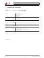
1
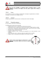
Installation- and user manual LCS-KD04 LC-Products B.V. tel. +31 (0)88 8111000 fax. +31 (0)88 8111009 email: [email protected] website: www.lc-products.nl ©LC-Products B.V. All rights reserved. No part of this publication may be reproduced in any form or by any means without permission of LC-Products B.V. Copyright © 2013 LC-Products B.V. LC-Products B.V. Installation- and user manual LCS-KD04 Content 1 Introduction..........................................................................................................3 1.1 Operation LCS-KD04 unit..................................................................................................................3 1.2 Connecting LCS units........................................................................................................................3 1.3 Communication..................................................................................................................................3 2 User interface........................................................................................................4 2.1 Display & Key ...................................................................................................................................5 2.2 LED indicators...................................................................................................................................6 3 Installation LCS-KD04...........................................................................................7 3.1 Tools and materials...........................................................................................................................7 3.2 Connection points of the LCS-KD04..................................................................................................7 3.2.1 Power.........................................................................................................................................8 3.2.2 Contrast......................................................................................................................................8 3.2.3 Connecting sensors....................................................................................................................8 3.2.4 Additional modules...................................................................................................................11 3.2.5 Use of the potential free contacts to related relais...................................................................12 3.3 Relais output functions....................................................................................................................13 3.4 Combine multiple LCS-KD04 units to 1 system..............................................................................15 3.4.1 Wired connection to a PC/laptop..............................................................................................15 3.4.2 Use of a virtual com port..........................................................................................................15 4 LCS Configuration software.................................................................................16 4.1 LCS Configuration...........................................................................................................................16 4.1.1 Application................................................................................................................................16 4.1.2 RS232 connection....................................................................................................................17 4.2 Main screen.....................................................................................................................................18 4.3 Settings and information..................................................................................................................19 4.3.1 Tank/sensor number................................................................................................................19 4.3.2 Tank settings/dimensions.........................................................................................................19 4.3.3 Sensor type & multi relais functionality (MR)...........................................................................21 4.3.4 Sensor parameters...................................................................................................................22 4.3.5 Alarm settings...........................................................................................................................24 4.3.6 General.....................................................................................................................................24 4.3.7 LCS Modem settings (system settings)...................................................................................25 4.3.8 Modem connection...................................................................................................................26 4.3.9 Actual information.....................................................................................................................26 4.3.10 Actual barometer info.............................................................................................................27 4.4 Tank overview..................................................................................................................................27 5 Technical specifications LCS-KD04......................................................................31 5.1 LCS-KD04........................................................................................................................................31 5.2 Configuration software.....................................................................................................................31 5.3 Extra hardware................................................................................................................................31 6 Declaration of confirmation.................................................................................32 Installation- and user manual: LCS-KD04 Version: 1.4 Page 2 of 32 Copyright © 2013 LC-Products B.V. LC-Products B.V. Installation- and user manual LCS-KD04 1 Introduction LCS-KD04 is an advanced and accurate system to measure fluid heights in storagetanks. The system can exist out of multiple units and every unit can accept a maximum of 4 sensors each. This manual is based on the firmware version 3.07, servicenumber 16 and LCS Configurator version 4.09, Servicenumber 16. New functionality is not mentioned in this manual. 1.1 Operation LCS-KD04 unit The main functions of the waTch LCS-KD04 unit are: • Monitor the fluid height (due several different sensors) • Switch on/off external equipment by relais • Generate alarms If an alarm is actuated (level, defect sensor, etc.) the unit can generate an alarm so the user is warned about the situation. 1.2 Connecting LCS units A maximum of 16 LCS-KD04 units can be connected together, to monitor 64 tanks. In section 3.4 is explained the procedure how to connect LCS-KD04 units into 1 total system. 1.3 Communication Each unit can be connected to a pc. Directly by using the RS232 or serial connector, or wireless by using a modem. If multiple units are connected, they all must be connected to the master unit nr.1. The other units can be readressed with LCS Adress configuration tool. Unit 2 will get Adress nr.2, unit 3 will get Adress nr.3, etc. Wireless connection by modem must be done by using an analogue modem (GSM or GPRS). Installation- and user manual: LCS-KD04 Version: 1.4 Page 3 of 32 Copyright © 2013 LC-Products B.V. LC-Products B.V. Installation- and user manual LCS-KD04 2 User interface This chapter will describe the user interface of the LCS-KD04. Display High – low indication Type Key Power indicator Picture 1: LCS-KD04 frontview Installation- and user manual: LCS-KD04 Version: 1.4 Page 4 of 32 Copyright © 2013 LC-Products B.V. LC-Products B.V. Installation- and user manual LCS-KD04 2.1 Display & Key The display shows information about the tankcontent off the (connected) tanks en de relais positions. 1. In standard mode the actual information (content in %, temperature in °C or switch position) is shown for all 4 tanks in once. Behind the sensornumber the relais position is shown. – = relais closed, / = relais open. 1 - 0% 2 / 18ºC 3 - 100% 4 / _/ _ 2. By pressing the key information of the next group of 4 sensors is shown (if present, sensor 5,6,7,8). The relais position is not mentioned in this mode. Only the : sign so you know it's infomation of the next LCS-KD04 unit connected in the system. 5: 9% 6: 89% 7: 99% 8: 43% 3. By double click the key, more detailed information is profided of tank 1 (tanknumber, relais position, content in litres, content in %, alarm if set and fluid heigth in mm). Press again the key to show the same information for tank 2, etc. After tank 4 the unit will go back to the original mode. 1- 13 L LOW 0% 5mm 4. Using the double click for the next 4 tanks will display the same information as mentioned in step 3. Instead of the relais position you see : so you know you have information of an other LCS-KD04 in the system. 5: 120 L 9% 70 mm 5. When the LCS-KD04 is equiped with a modem, you can press the key till you see the information of the provider and the signal strength. The * sign will pop up if there is connection by modem with the unit. Repressing the key or a time lap of 1 minute is enough to go back to the standard mode setting. KPN * 92 When an alarm level is reached (high- or low level) the buzzer can go off if set. Pressing the key will stop the buzzer. Installation- and user manual: LCS-KD04 Version: 1.4 Page 5 of 32 Copyright © 2013 LC-Products B.V. LC-Products B.V. Installation- and user manual LCS-KD04 2.2 LED indicators The LCS-KD04 is provided with 9 led indicators. Power (green led): When power is available the green led is shining. A flashing green led means the barometer is in error. Level indication (red leds): Every tank can be configured with minimum and maximum levels (soft-alarm and hard-alarm values). When a setted soft-alarm (prewarning) value is reached, the red led will flash. Lower led is minimum level, upper led is maximum level. When a setted hard-alarm (warning) value is reached, the red led will shine continuously. Lower led is minimum and upper led is maximum level. Maximum level Flashing = soft alarm Continuously = hard alarm Minimum level Flashing = barometer error Power Continuously = power available Drawing 1: determination leds When both red leds are flashing a sensor error is indicated. Sensor is defect or incorrect connected. Installation- and user manual: LCS-KD04 Version: 1.4 Page 6 of 32 Copyright © 2013 LC-Products B.V. LC-Products B.V. Installation- and user manual LCS-KD04 3 Installation LCS-KD04 This chapter will describe the installation of the LCS-KD04. Also building a system out of multiple units is mentioned and how to connect a sensor to a unit. 3.1 Tools and materials For using a LCS-KD04 you need at least the following materials and software: - Sensor - Probe - Configuration software with RS232 cable 3.2 Connection points of the LCS-KD04 Removing the access cover (picture 2) will reveal all connection points. A sticker inside the access cover is showing important information. See below the schematic details: Picture 2: access cover Picture 3: connection scheme Installation- and user manual: LCS-KD04 Version: 1.4 Page 7 of 32 Copyright © 2013 LC-Products B.V. LC-Products B.V. Installation- and user manual LCS-KD04 Make sure the LCS-KD04 is powerless before connecting sensors or other equipment. So remove the adapter from the power supply before making a connection. 3.2.1 Power The LCS-KD04 is powered by an adapter 230VAC/24VDC. This adapter is supplied with the LCS-KD04. The adapter is connected to the 24V/GND connector. 3.2.2 Contrast Turning the potentiometer (“contrast” picture 3) will adjust the contrast of the display. 3.2.3 Connecting sensors You can connect 4 sensors per LCS-KD04 unit. The follwing type of sensors can be connected: • Analogue pressure sensor: measuring the content level due pressure • Digital pressure sensor: measuring the content level due pressure (digital interface is needed) • Vacuum sensor: measuring the vacuum (gap between outher shell-inner shell of tank or piping) • Ultrasonic sensor: measuring level fluid due sound waves • Floatswitch: switch contact on a set level • Analogue temperature sensor: measuring the temperature, as an extra protection of your installation • Digital temperature sensor: measuring temperature (digital interface is needed) • Capacitive sensor: measuring fluid levels based on fluid contact to the tube Pressure sensors must always be fixated due a probe supplied by LC-Products. Without this probe no garantee is granted. Installation- and user manual: LCS-KD04 Version: 1.4 Page 8 of 32 Copyright © 2013 LC-Products B.V. LC-Products B.V. Installation- and user manual LCS-KD04 Explanation of different sensor types: 3.2.3.1 No sensor Sensor type No sensor 3.2.3.2 Led status Deactivated Analogue pressure sensor Sensor type Relative pressure 4..20mA Absolute pressure 4..20mA comp->volume Led status Activated while alarm Activated while alarm Activated while alarm Absolute pressure 4-20mA comp->presurre Activated while alarm Absolute pressure 4..20mA 3.2.3.3 Description No sensor is connected Description Relative analogue pressure sensor Absolute analogue pressure sensor Absolute analogue pressure sensor. Measuring compensating volume of other absolute analogue pressure sensor Absolute analogue pressure sensor. Measuring compensating pressure of other absolute analogue pressure sensor Digital pressure sensor Digital sensors must be connected to a RS485 sensor interface, see paragraph 3.2.4.2 . RS485 sensor interface (partnumber 5.14.006). Sensor type Led status Description Keller Serie30 pressure (rs485#1) comp->volume Activated while alarm Absolute digital pressure sensor, connected to #1 of the RS485 sensor interface. Measuring also for compensating volume of other absolute digital pressure sensor Keller Serie30 pressure (rs485#1) comp-> pressure Activated while alarm Absolute digital pressure sensor, connected to #1 of the RS485 sensor interface. Measuring also for compensating pressure of other absolute digital pressure sensor Keller Serie30 pressure (rs485#2) comp->volume Activated while alarm Absolute digital pressure sensor, connected to #2 of the RS485 sensor interface. Measuring also for compensating volume of other absolute digital pressure sensor Keller Serie30 pressure (rs485#2) comp-> pressure Activated while alarm Absolute digital pressure sensor, connected to #2 of the RS485 sensor interface. Measuring also for compensating pressure of other absolute digital pressure sensor Installation- and user manual: LCS-KD04 Version: 1.4 Page 9 of 32 Copyright © 2013 LC-Products B.V. LC-Products B.V. Installation- and user manual LCS-KD04 3.2.3.4 Vacuumsensor Sensor type Vacuum 4..20mA 3.2.3.5 Led status Activated while alarm for vacuum measuring, Ultrasonic sensor Sensor type Ultrasonic 4-20mA (max..min) Ultrasonic 4-20mA (min..max) 3.2.3.6 Description Analogue sensor leakage detection Led status Activated while alarm Activated while alarm Description Ultrasonic sensor with 4-20mA output. 4mA = maximum beam, 20mA is minimum beam Ultrasonic sensor with 4-20mA output. 4mA = minimum beam, 20mA is maximum beam Switch Remark: If a switch is used, only one level can be detected. If a second level detection is needed than you have to connect a second switch to a second connection. Sensor type Led status Switch Normally Open → Relais Activated while alarm Switch Normally Closed → Activated while Relais alarm Switch Normally Open → Alarm Activated while alarm Switch Normally Closed → Activated while Alarm alarm 3.2.3.7 this this this this Temperature sensor Sensor type Temp 4..20mA Led status Activated while alarm Keller Serie30 temp. (rs485#1) Activated while alarm Keller Serie30 temp. (rs485#2) Activated while alarm 3.2.3.8 Description Floatswitch, type normaly open. With setting an equal relais funtion is activated Floatswitch, type normaly closed. With setting an equal relais funtion is activated Floatswitch, type normaly open. With setting only the alarm is activated Floatswitch, type normaly closed. With setting only the alarm is activated Description Analogue temperature sensor 4-20mA. Equal to PT100 sensor. PT100 interface is needed. (Paragraph: 3.2.4.1 : PT100 interface). Digital temperature sensor type Keller, connected to #1 of the RS485 sensor interface (see digital pressure sensors) Digital temperature sensor type Keller, connected to #2 of the RS485 sensor interface (see digital pressure sensors) Capacitive sensor Sensor type Capacitive sensor 4-20mA (mn..mx) Led status Activated while alarm Installation- and user manual: LCS-KD04 Description Capacitive sensor with 4-20mA output. 4mA = minimum , 20mA is maximum Version: 1.4 Page 10 of 32 Copyright © 2013 LC-Products B.V. LC-Products B.V. Installation- and user manual LCS-KD04 3.2.4 3.2.4.1 Additional modules PT100 interface For using a PT100 sensor, a PT100 interface is needed. This interface can be ordered at LC-Products (partnumber: 5.01.014 “Interface for temperature sensor PT-100”). See picture 4 how to connect the PT100 sensor to a convertor: There are multiple kinds of PT100 sensors available, all with different connections. Picture 4 is showing the type with 2 connections. – – A PT100 sensor with 3 wires is to be connected so that the wires with the same colour are connected to 1&2. The other wire is to connect to 3&4. A PT100 sensor with 4 wires is to be connected so that the wires with the same colour are connected to 1&2. the other wires with the same colour connect to 3&4. 3.2.4.2 RS485 sensor interface (partnumber 5.14.006) Digital sensors can be connected to the LCS-KD04 by using a RS485 sensor interface. This interface has a flat cable which fits to the controller unit (below the front panel). The RS485 interface can only be mounted in a LCS-KD04 with unitadress 2 or higher and without a modem. If your LCS-KD04 has a modem, please use a second LCS-KD04 to connect the digital sensors and interface. Picture 5: waTch LCS RS485 sensor interface Picture 5 shows a RS485 interface. Two connectors (input #1 & input #2) for digital sensors, with 3 contactpoints: A, B and ground. A&B is used for data communication. GND is not used. Mount the interface according picture 6. Picture 6: Mounting position interface into LCS-KD04 Installation- and user manual: LCS-KD04 Version: 1.4 Page 11 of 32 Copyright © 2013 LC-Products B.V. LC-Products B.V. Installation- and user manual LCS-KD04 3.2.5 Use of the potential free contacts to related relais Every tank (sensor) input has 1 related relais output. This potential free output can be used in 2 different ways: normally open (NO) or normally closed (NC). (see the scheme according picture 3: connection scheme) Attention: the standard relais position is when the unit is powerless. Equal to an alarmlevel is reached (high or low level, depending on set relais function). A more detailed description of relais functions is mentioned in paragraph 3.3. The alarm levels and the relais functions can be configurated with our configuration software (see chapter 4). Installation- and user manual: LCS-KD04 Version: 1.4 Page 12 of 32 Copyright © 2013 LC-Products B.V. LC-Products B.V. Installation- and user manual LCS-KD04 3.3 Relais output functions If the LCS-KD04 is off power, the relais is switched to normally closed. The relais functions can be configured in multiple settings: Off: Relais is not activated, standard in NC position. Afbeelding 7: Relais functie LCS Configurator On: between min. and max. (AAN: tussen min. en max.) The tank is configurated with one of the optional sensors. The related output (tank 1 = relais 1, etc) will switch as follows: Measured level is inbetween the minimum and maximum hard alarm level, the relais switches to NO. Measured level is below the minimum hard alarm level, the relais is switched to NC. Measured level is above the maximum hard alarm level, the relais is switched to NC. On: above max. Off: below min. (AAN: hoger max. UIT: lager min.) The tank is configurated with one of the optional sensors. The related output (tank 1 = relais 1, etc) will switch as follows: Measured level is above the maximum hard alarm level, the relais is switched to NO. Measured level is below the minimum hard alarm level, the relais is switched to NC. On: below min. Off: above max. (AAN: Lager min, UIT: hoger max.) The tank is configurated with one of the optional sensors. The related output (tank 1 = relais 1, etc) will switch as follows: Measured level is below the minimum hard alarm level, the relais is switched to NO. Measured level is above the maximum hard alarm level, the relais is switched to NC. Installation- and user manual: LCS-KD04 Version: 1.4 Page 13 of 32 Copyright © 2013 LC-Products B.V. LC-Products B.V. Installation- and user manual LCS-KD04 The valve of the overfill protection must be connected in such a way that the valve is closed when the relais is in NC position. The alarm levels, configured with our LCS Configuration software (see paragraph 4.3.5), are only used to activate the buzzer, send a sms by modem, etc. The relais function will not be defined by these levels. In case of the overfill protection function the relais functions are strictly defined. Special: Overfill protection valve (Overvulbeveiliging afsluiter) – – – – When the unit is off power, the relais is switched to NC (and the valve is closed) When the sensor is defect, the relais is switched automatically to NC (and the valve is closed) When the measured level is less than 95%, the relais is switched to NO When the measured level is more than 95%, the next cycle will start: ● Relais will switch to NC (valve closed) ● After 30 seconds the relais will switch to NO (valve open) ● After 140 seconds the relais will switch to NC again (valve closed) ● Relais remains in the NC position till the measured content is below 80%. Than relais will switch to NO (valve open) Special: Overfill protection pump (Overvulbeveiliging pomp (afgewerkte olie)) – – – – When the units is off power, the relais is switched to NC (and the valve is closed) When the sensor is defect, the relais is switched automatically to NC (and the valve is closed) When the measured level is less than 95%, the relais is switched to NO When the measured level is more than 95%, the next cycle will start: ● Relais will switch to NC (pump off) ● Relais remains in the NC position till the measured level is below 80%. Than relais will switch to NO (pump on) Above mentioned switch levels and cycle times are different in the LCS-KD04 KIWA overfill protection unit. For these setting see our manual LCS-KD04 KIWA. Installation- and user manual: LCS-KD04 Version: 1.4 Page 14 of 32 Copyright © 2013 LC-Products B.V. LC-Products B.V. Installation- and user manual LCS-KD04 3.4 Combine multiple LCS-KD04 units to 1 system In total 16 LCS-KD04 units can be combined to 1 system. Communication off all data is through the master LCS-KD04 (allways unit 1). Data is available from a distance by serial or modem connection. LCS-KD04 units can be connected together by using the RS485 connector. Connect the A-pole of the 1st unit to the A-pole of the 2nd unit. Also connect the B-pole of the 1st unit to the B-pole of the 2nd unit. The ground (GND) is not used. Every unit has to have a unique unit number before realize the fysical connection. The unit numbers can be set by using LCS Adress config-software. Also only unit 1 can have a active barometer. Therefore you have to disconnect to barometers from unit 2,3,4, etc. to avoid conflicts. This can be done by disconnecting the wires from the controllerboard. The LCS Address software is available on our website: www.lc-products.nl After installing the software on your computer you can make a connection with the unit by using the RS232 interface cable. In the software you select: change unitadress, for making Picture 8: Barometer connection press “connect”. The unit adress number and also the firmware version- / productnumber will pop up. This unit adress number can be changed from 1-16. After clicking “enter” the new adress number is saved in the LCS-KD04. 3.4.1 Wired connection to a PC/laptop A wired connection between PC/laptop and LCS-KD04 can be realised by using the RS232 connector. You need to use a special cable (partnumber 6.04.009). When the PC/laptop has no serial entry, than use an additional RS232-USB convertor (partnumber N0.00.020). 3.4.2 Use of a virtual com port LC-Products delivers also RS232-TCP/IP converters, for serial communication with your local network. (ethernet, TCP/IP). Doing this virtual com-ports will be created on the PC. For more details please check our Installation manual of the Nport (partnumber 9.06.006: waTch TCP/IP module). To use this converter you connect it to a standard computer cable from your local network. Between the TCP/IP converter and the LCS-KD04 unit you can use the RS232 (see paragraph 3.4.1). Installation- and user manual: LCS-KD04 Version: 1.4 cable. Page 15 of 32 Copyright © 2013 LC-Products B.V. LC-Products B.V. Installation- and user manual LCS-KD04 4 LCS Configuration software This chapter is explaining how the unit must be configured. The configuration software is available on our website www.lc-products.nl. 4.1 LCS Configuration 4.1.1 Application LCS configurator software is available on our website: www.lc-products.nl. Software is self-installing and ready for use. After starting the application the tank overview will pop up of all 64 tanks/sensors. Picture 9: Overview tanks LCS-configurator Double clicking on a tank or on the icon tankparameters. (see paragraph: 4.2) you will enter the configuration page to adjust the Installation- and user manual: LCS-KD04 Version: 1.4 Page 16 of 32 Copyright © 2013 LC-Products B.V. LC-Products B.V. Installation- and user manual LCS-KD04 4.1.2 RS232 connection Effectuate a connection with the LCS-KD04. Either a direct connection (RS232) or by modem. The connector on the PCA (printed circuit assembly) is marked with a label “RS232” (see paragraph 3.2 picture 3: connection scheme). To ensure Select Select Select a correct coupling, the related com-port is to be set in the LCS configuration software. <configuration> and than <settings> <communication> the correct com-port to be used Picture 10: LCS configuration–communication settings To achieve a modem-connection click the box “use modem”. A √ will appear. How to fill in the cellphone number of the M2M simcard is explained in paragraph 4.3.8 . In the right bottom corner 2 squares are visible. The right square refers to the com-port setting and the left square to the connection with the unit. If the squares turn from red into green you have online connection with the LCS-KD04 unit. Picture 11: Status connection Installation- and user manual: LCS-KD04 Version: 1.4 Page 17 of 32 Copyright © 2013 LC-Products B.V. LC-Products B.V. Installation- and user manual LCS-KD04 4.2 Main screen 4.3.1 4.3.7 4.3.6 4.3.2 4.3.3 4.3.8 4.3.4 4.3.10 4.3.5 4.3.9 Picture 12: Configuration screen In picture 12 you see 10 numbered fields. In paragraph 4.3 you will find the explanation with more detailed information. Installation- and user manual: LCS-KD04 Version: 1.4 Page 18 of 32 Copyright © 2013 LC-Products B.V. LC-Products B.V. Installation- and user manual LCS-KD04 4.3 Settings and information 4.3.1 Tank/sensor number In this box you can select the tank/sensor to configure (1 – 64). 4.3.2 Tank settings/dimensions Picture 13: Tank/sensor selection Different tank shapes can be configured: • Vessel (cilindrical vessel, flat bottom) • Cylinder (horizontal cylinder, flat sides) • Cube • Prism • Horizontal cylinder (convex sides) • Vertical cylinder (convex sides) Picture 14: Tank settings • Truncated cone • Tank with contentlist: every fluid height refers to content in litres. In between values is based on linear interpolation. Per tank shape all necesarry dimensions can be set. (for example: hight, width, length, diameter, etc). Type tank Vessel Parameters Cylinder Installation- and user manual: LCS-KD04 Version: 1.4 Page 19 of 32 Copyright © 2013 LC-Products B.V. LC-Products B.V. Installation- and user manual LCS-KD04 Type tank Cube Parameters Prism Horizontal cylinder with convex sides Vertical cylinder convex sides with Installation- and user manual: LCS-KD04 Version: 1.4 Page 20 of 32 Copyright © 2013 LC-Products B.V. LC-Products B.V. Installation- and user manual LCS-KD04 Type tank Truncated cone Parameters Tank with contentlist If your tank is different than the standard shapes, you can use a contentlist from the tankproducer. This list can be used in a LCS-KD04 unit. For more detailed information please contact LC-Products B.V. 4.3.3 Sensor type & multi relais functionality (MR) Multiple sensors can be connected to a LCS-KD04 unit: 1 Relative or absolute analogue pressure sensors, 4-20mA for content measuring 2 Vacuumsensor 4-20mA, for measuring vacuum pressure between outher shell and inner shell of tanks and pipings 3 Ultrasonic sensor for content measuring, without fluidcontact 4 Temperature sensor 5 Floatswitch (normally open or normally closed) 6 Digital pressure/temperature sensor (combined) See paragraph 3.2.3 for detailed info of the sensors. Depending of the type of sensor different parameters can be set. Picture 15: Type sensor to select The multi relais functionality makes it possible to use outputs of different relais combined with 1 sensor. So theoretical you can control 64 relais (hard alarm levels) using only 1 sensor. Selecting the square MR will activate the multi relais functionality and you can choose the correct reference sensor. It will also deactivate the responding sensor input. So you can use the responding relais (tank 1 = relais 1, tank 2 = relais 2, etc.)and combine it with different sensor input numbers. To do this you select the button in the pop up <choose sensor> (Kies meetsensor). Now select the sensor you want to use as a reference. Installation- and user manual: LCS-KD04 Version: 1.4 Page 21 of 32 Copyright © 2013 LC-Products B.V. LC-Products B.V. Installation- and user manual LCS-KD04 Picture 16: Multi relais functionality The selected sensor will pop up with default settings. You can not alterate it. The relais functionality can be altered in the setting you need, and also the hard- and soft alarm levels can be set. Activating the multi relais functionality, it will be displayed as relais 2 is connected to sensor 1. 4.3.4 Sensor parameters Depending of the type of sensor, different parameter fields will appear. The following fields can appear: Pressure max. (mbar): The maximum pressure level of the sensor in mbar Picture 17: Sensor parameters Pressure min. (mbar): The minimum pressure level of the (vary per sensor type) sensor in mbar. Bottom-correction (mm): Distance between the sensortip and the bottom in mm millimeters. Sensortip on the bottom = 20 mm. Max. hight (mm): Maximum value pressure of the sensor in millimeters. Min. hight (mm): Minimum value pressure of the sensor in millimeters. Span max. (mm): Distance between bottom of the tank and ultrasonic sensor in millimeters. Density (gram/liter): Density of the fluid in the tank in gram/litre. Max. Temperature (ºC): Maximum value of the sensor in degrees Celsius. Min. Temperature ( ºC): Minimum value of the sensor in degrees Celsius. Max. level (%): Maximum value of the sensor in percentage. Min. level (%):Minimum value of the sensor in percentage. Tolerance (%): Tolerance (margin of error) off the sensor in percentage. Choose comp. sensor: Here you choose a compansation sensor to calculate a absolute value. Check table of the next page for parameter setting per sensor. Installation- and user manual: LCS-KD04 Version: 1.4 Page 22 of 32 Copyright © 2013 LC-Products B.V. LC-Products B.V. Installation- and user manual LCS-KD04 Sensor No sensor Relative pressure 4..20mA Ultrasonic 4-20mA (max..min) Ultrasonic 4-20mA (min..max) Absolute pressure 4..20mA Absolute pressure 4-20mA comp->volume Absolute pressure 4-20mA comp->pressure Temp 4..20mA Keller Serie 30 pressure (RS485#1) comp->volume Keller Serie 30 pressure (RS485#1) comp->pressure Keller Serie 30 pressure (RS485#2) comp->volume Keller Serie 30 pressure (RS485#2) comp->pressure Keller Serie 30 temp (RS485#1) Keller Serie 30 temp (RS485#2) Switch Normally Open → Relais Switch Normally Closed → Relais Switch Normally Open → Alarm Switch Normally Closed → Alarm Vacuum 4..20mA Capacitive sensor 4..20mA (min..max) Installation- and user manual: LCS-KD04 Parameters – – Pressure max – Tolerance – Bottom correction – Density – Heigth max. – Height min. – Span max. – Heigth max. – Heigth min. – Span max. – Pressure max. – Pressure min. – Bottom correction – Density – Pressure max. – Pressure min. – Bottom correction – Density – Choose compensation sensor – – – – – – – – – – – – – - Pressure max. Pressure min. Choose comp. sensor Max. Temperature Min. Temperature Bottom correction Density Choose comp. sensor Choose comp. sensor Bottom correction Density Choose comp. sensor Choose comp. sensor – – – – Pressure max. Pressure min. Max. heigth Min. heigth Version: 1.4 Page 23 of 32 Copyright © 2013 LC-Products B.V. LC-Products B.V. Installation- and user manual LCS-KD04 4.3.5 Alarm settings 2 types of alarm can be set in the LCS-KD04 unit: soft alarm and hard alarm. The soft alarm is a pre warning (led will flash), meaning that a undesirable situation is comming up (hard alarm). The hard alarm (led burns continuously) is activating the buzzer if set, or activates the relais or will send a sms by modem. Picture 18: alarm settings The relais functionality between min. and max. will give a bandwidth (hysteresis) to set. This is an extra boundary before the relais will switch again after the hard alarm triggering. This avoids lapping of the relais. Below the alarmsetting also the relais function can be selected. See paragraph 3.3 Relais output functions for a more detailed description of all relais functions. Attention: the relais will only be activated on the configured hard alarm levels. Exceptions are the temperature sensors. Temperature sensors activate the relais also on the soft alarm levels. 4.3.6 General In this field information is given about the firmware release and product number. The firmware release exist out of a letter (picture 19: K....) which reflects the type of modem on board. See below table: No GPRS GPRS No modem K k Modem type 1 L l Modem type 2 M m Modem type 3 N n After the letter a number will follow (picture 19: .. 2.3.7). 2 = to the KD04 (2= KD04, 3= KD04 KIWA). 3.7 = to the firmware release. Picture 19: General If a GSM/GPRS modem is mounted, and the simcard is placed, information about the provider (name) and the GSM/GPRS signal strength will be shown (0-100%). Installation- and user manual: LCS-KD04 Version: 1.4 Page 24 of 32 Copyright © 2013 LC-Products B.V. LC-Products B.V. Installation- and user manual LCS-KD04 4.3.7 LCS Modem settings (system settings) Modem: The modem of the LCS-KD04, can be set in 4 modes when the simcard is installed. – No modem – Analogue modem – GSM modem – GSM/GPRS modem LCS ID: Identification of the LCS-KD04. Normally the cellphone number is used to identify the unit. Picture 20: System settings Tel.nr. Out / Server IP: Telephone number to communicate with when a hard low alarm level is reached. (the LCS-KD04 will make a call to this number). To achieve and receive this call a special application is needed and can be applied by LC-Products. When a data modem is used the IP adress of the server can be added to achieve a communication. SMS centrale: Fill in the cellphone number of the SMS service station of your provider. Without this number SMS messages can not be send when a hard-alarm occurs. For your help: KPN = +31653131313 Vodafone = +316540881000 T-Mobile = +31624000000 Ben = +31624000000 Telfort = +31626000230 SMS Tel.nr: Fill in the cellphone number of the receiver of the sms message. Barometer: The barometer is always activated. When the barometer is defect, a SMS message will be send when this square is selected. (see: 4.3.10 ). SMS Alarm: Selecting this square will send a SMS message when a hard alarm level is reached (see SMS Tel.nr.). When the SMS service station + SMS tel nr are filled in correctly a SMS message will be send, independent if the “SMS” alarm is selected or not, when a sensor is defect. The LCS-KD04 will send out this warning for security reasons only. Buzzer: Selecting this square will active the buzzer when a hard alarm level is reached. Settings in the LCS-KD04 configurator will be activated and stored after clicking <apply> (Toepassen). The set values will disappear for a short period of time, and than appear again on your screen. All settings are saved now in the LCS-KD04. Attention: for using the GSM modem, always deactivate the PIN code of the GSM/GPRS sim-card!! Installation- and user manual: LCS-KD04 Version: 1.4 Page 25 of 32 Copyright © 2013 LC-Products B.V. LC-Products B.V. Installation- and user manual LCS-KD04 4.3.8 Modem connection Actual information about the connection with the LCS-KD04 is shown. A text will appear when there is a good connection with the LCS-KD04. For wireless configuration the square “modem” is to be selected in the communication settings. In the config screen fill in the cellphone number of the LCS-KD04. You can also select a cellphone number out of the telephone book (use ‘<<’). The cellphone numbers are stored in your PC. Not in the LCS-KD04. Picture 21: status connection The connection will be established after selecting “calling” (BELLEN). The connection will be disabled after selecting “break” (Verbreken). 4.3.9 Actual information Actual information depends on the selected type of sensor. So the textblock name can change in: actual tankinformation, actual switch positions or actual temperature. Actual tankinformation Indication of the present content in liters, fluid level in mm and content in percentage or pressure in millibar. Actual switch position With switch positions only alarm and errors are shown as: normal, error, to low and to high. Actual temperature Indication of temperature in degrees Celsius Error and alarm warnings are always visible in this field: Normal: normal level Error: sensor error Picture 22: actual tankinfo Te low: level is to low (beneath the hard alarm setting) Te high: level is to high (above the hard alarm setting) Actual alarm: When a sensor or barometer generates an alarm, both can be resetted by clicking the square and press reset. Installation- and user manual: LCS-KD04 Version: 1.4 Page 26 of 32 Copyright © 2013 LC-Products B.V. LC-Products B.V. Installation- and user manual LCS-KD04 4.3.10 Actual barometer info The barometer will compensate the local airpressure to achieve an accurate measuring. This box shows the local airpressure and the software release of the barometer. Evenso the use of a relative pressure sensor is possible. Normal: barometer controller is operating correctly. Error: barometer controller is not active or defect. The green power led will flash when this occurs. Picture 23: Barometer info 4.4 Tank overview Press this button and the tank overview screen will start up. This is an overview of all tanks or sensors. Names of tanks can be altered by clicking the right mouse button when you point the cursor on the tank. In the pop up you can change the name. Picture 24: Select tanks 1. Image → Present all tanks: all tanks are tagged and shown. 2. Image → Deselect all: all tanks are de-tagged. Now you can select those tanks you want to view as standard. 3. Image → present all tanks with a tag: Only the tagged tanks will appear. Installation- and user manual: LCS-KD04 Version: 1.4 Page 27 of 32 Copyright © 2013 LC-Products B.V. LC-Products B.V. Installation- and user manual LCS-KD04 Extra explanation about the tankoverview in the LCS configurator. Picture 25: Tankoverview LCS-configurator Symbol Description Temperature or pressure value Horizontal beam Measuring contents Vertical cylindrical tank High alarm level (hard) H: <value> Low alarm level (hard) L: <value> Installation- and user manual: LCS-KD04 Version: 1.4 Page 28 of 32 Copyright © 2013 LC-Products B.V. LC-Products B.V. Installation- and user manual LCS-KD04 Actual value, normal situation Coloured Blue Actual value, alarming situation Coloured Red Sensor error Exclamation mark Sensor is not defined or unit of the sensor is not present Cross Installation- and user manual: LCS-KD04 Version: 1.4 Page 29 of 32 Copyright © 2013 LC-Products B.V. LC-Products B.V. Installation- and user manual LCS-KD04 Graph By selecting “graph” an extra program will start up. This program shows a detailed graphic overview of the contents history. To use this feature you have to create a database. 1. For this go to settings in the LCS Configurator and select a database directory. The frequence of datastacking can be set. 2. Start the program again for actualisation of the settings. 3. Data from the sensors is stacked now in the database. 4. By clicking the “graph” button the stored info is visualised in a graph. Installation- and user manual: LCS-KD04 Version: 1.4 Page 30 of 32 Copyright © 2013 LC-Products B.V. LC-Products B.V. Installation- and user manual LCS-KD04 5 Technical specifications LCS-KD04 5.1 LCS-KD04 Power LCS-KD04: adapter 230 VAC 50/60Hz in, 24 VDC out, 6 Watt Operating temperature: 0-55 ºC Humidity: 0-90% relative humidity, not condensating Inputs: • 4-20mA sensor (pressure, temperature, vacuum, ultrasonic) • Switch (on/off) Accuracy: • Analogue pressure sensor and vacuum sensor: 0,5% of the full scale • Digital pressure sensor: 0.1% of the full scale User interface: • 2 red leds for every sensor; flashing means soft alarm, continuously means hard alarm • Green led is power indication, flashing means barometer error • 2 x 16 characters LCD Output: • 4x potential free contacts, max. 5A/230VAC; functionality depends on settings Outside dimensions: 215 x 210 x 95 mm Protection class : IP54 5.2 Configuration software Min. system requirements: depends on Windows operating system. Pentium-II, minimal 64 Mb RAM, minimal 10 Mb free hard disk space. Operating system: Windows 95/98®, Windows NT4®, Windows 2000®, Windows Server 2003®, Windows XP®, Windows VISTA®, Windows 7®. PC-link: free RS-232 port, USB-RS232 convertor; for local network a TCP/IP module is used. Modem communication: based on a analogue modem. Phoneline or wireless (GSM/GPRS). 5.3 Extra hardware A LCS-KD04 system can be extended with the following modules: waTch Extern display: This module shows the fluid height in mm of 1 sensor. WaTch Connection box Fuelpos: this module is interfacing with a FuelPos system of Tokheim. WaTch Connection box 4-20 mA: this module will generate the fluid height % into a 4-20 mA signal. 4mA = 0%, 20mA = 100%. For more information about these modules please contact LC-Products or visit our site: www.lc-products.nl. Installation- and user manual: LCS-KD04 Version: 1.4 Page 31 of 32 Copyright © 2013 LC-Products B.V. LC-Products B.V. Installation- and user manual LCS-KD04 6 Declaration of confirmation Declaration of confirmation 89/392/CEE Name: LC-Products BV. Bedrijvenpark Twente 30 7602 KB Almelo Netherlands +31 (0)88 8111000 +31 (0)88 8111009 [email protected] Telephone: Fax: Email: Declares that this product: Product name: Product number(s): Power adapter: waTch LCS-KD04 9.01.033 LCS-KD04 basic unit (equiped with relais and barometer) 9.01.034 LCS-KD04 basis unit (equiped with a GSM/GPRS modem) Model GSU15E-6 Is produced according the following standards: EMC and safety EN 61000-6-3 (2001) EN 61000-6-2 (2001) EN 61000-3-2 (1995) + A1 (1998) + A2 (1998) EN 61000-3-3 (1995) We declare with all accountability the product is produced according the directive 89/392/CEE and the subsequent directions. Almelo, 2012 Installation- and user manual: LCS-KD04 Version: 1.4 Page 32 of 32 Copyright © 2013 LC-Products B.V.