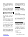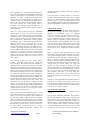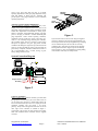
1
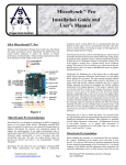
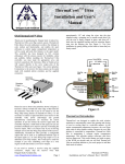
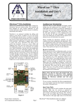
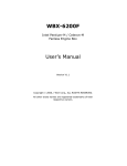
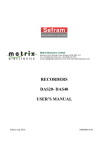
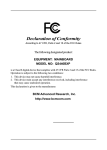
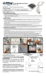
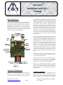
TM AutoGlow Installation and User’s Manual OSA AutoGlow™ Thank you for purchasing the Oregon Scale Aviation Inc. AutoGlow automatic glow plug control system. AutoGlow allows the model aviation enthusiast to achieve outstanding performance and functionality, while providing an unprecedented level of safety in the operation of glow engine powered model aircraft. This controller has been designed by R/C aviation enthusiasts with the utmost concern for reliability, safety and usability. Ground Blk/Brn +5V Red/Red Signal Yel/Or Receiver Input LED Reversed Throttle Servo Out Throttle Servo Out Glow Temperature Adjustment Automatic Mode Velocity Sensing EEPROM Glow temperature monitoring and controlling insures that long periods of idle will not extinguish the glow plug and cause an engine stoppage or loss of performance during take-off or landing due to a cold or cool plug. AutoGlow also includes a stick acceleration sensing feature that automatically sets the glow current to the full power setting when the stick is rapidly moved from a low throttle setting to a high throttle setting. This condition can occur when the pilot aborts a final landing approach and advances the throttle from a near idle position to a high throttle setting. It can also occur anytime in a flight routine where rapid stick movement occurs. This feature insures consistent engine performance during the critical final approach and landing phase of flight. The user can program 3 setpoints in memory. The first is a point above which AutoGlow will not provide any current to the glow plug. This is usually set at about the ¾ throttle position to insure that during high speed flight, the onboard glow battery is conserved. The second is a point below which the AutoGlow will provide full power to the glow plug. It is typically set slightly above the normal idle position. This is useful for both engine start-up and insuring a hot plug during final approach and landing. Finally a third setpoint allows the user to set a “kill point” Any throttle stick position below this point will prohibit AutoGlow from providing power to the glow plug. This is useful in stopping the engine using a kill switch or trim tab setting. AutoGlow even includes a throttle output connector and a reversed throttle output connector eliminating the need for Y-Connectors during installation. Engine Ground Glow Plug 1.2V Battery 1.2V Battery - + Figure 1 AutoGlow Introduction There are no pre-flight stick movements or settings required by AutoGlow. Simply turn on the transmitter, turn on the receiver, start the engine and fly with confidence knowing that AutoGlow is constantly monitoring the glow plug temperature. AutoGlow Installation AutoGlow was designed to provide on-board glow for engine startup and to automatically maintain a minimum glow plug temperature throughout the flight envelope. Oregon Scale Aviation Inc. www.oregonscaleaviation.com In summary, AutoGlow serves as an On-Board glow for engine start-up, an in-flight glow plug temperature controller and a full power glow heater during rapid stick acceleration or while on final approach and landing! Page 1 Before installing AutoGlow, it is recommended that you complete the “normal” installation of the throttle servo and radio in your aircraft. You should complete all full throttle and idle adjustments (both mechanical and transmitter AutoGlow Installation and User’s Manual Doc # 108101 adjustments), and as a safety measure, insure that you can stop the engine by reducing the throttle stick and throttle trim tab to their lowest positions or through the use of a kill switch on the transmitter. Once you have completed the aircraft radio and servo installation and throttle adjustments, you can proceed with the AutoGlow installation. Connect the receiver throttle output to the AutoGlow input as shown in Figure 2. This requires a female to female connector for your radio system. If you cannot purchase a female to female connector, you can build one using an aileron extender and the supplied connector. Please refer to the “Connector Installation” section at the end of this document for details. Always insure correct polarity as shown in Figure 1. Please insure that the power and ground leads are properly connected to AutoGlow before applying power to the system. Reversing power and ground may damage the AutoGlow controller and void your warranty. Connect the Throttle servo to the “Throttle Out” connector on the AutoGlow controller. The reversed output is generally not used in a single engine installation, but may be required if more than one AutoGlow is used in an aircraft. This can occur in twin or multi-cylinder installations. Next mount the LED in a location of your choice insuring that it is visible during engine start-up and operation while the aircraft is in the “pit”. Some builders prefer to mount the LED in the cockpit so that it is visible through the clear canopy and is shaded from direct sunlight. Plug the LED into the AutoGlow controller referring to Figure 1. Connect the engine glow plug to the “Glow Plug” wire on the AutoGlow controller. This can be accomplished using a commercially available glow plug connector. Connect the engine ground to the “Engine Ground” wire on the AutoGlow controller. Insure that the receiver ground wire is not connected to the engine in any way. Finally, connect a 1.2V glow battery to the “Battery +” and “Battery –“ wires of the AutoGlow, being careful to observe all polarities. In general a lightweight 2000mAH NiMH cell will provide adequate capacity for about 40 minutes of continuous glow at full power. This should be adequate for 5 flights or more (assuming reasonably timely startup, taxi and landing times). If you feel you need more flight time capability, simply increase the size of the glow battery remembering that the average glow plug consumes about 3A of current when fully lit. It is highly recommended that you also add a switch in either the Battery + or the Glow Plug wire as a safety measure to insure that the glow plug cannot be lit while hand cranking the engine. It is also recommend that you add a connector or charging jack to the 1.2V battery to allow it to be conveniently charged. The 1.2V battery should be disconnected from the AutoGlow unit during charging if attempting to charge both the Oregon Scale Aviation Inc. www.oregonscaleaviation.com Page 2 receiver battery and the glow battery at the same time. Most battery chargers and cyclers cannot charge two or more batteries installed in an aircraft if their grounds are in any way connected. AutoGlow connects the ground of the receiver battery to the ground of the 1.2V battery. See Figure 2. System Connection Diagram for correct wiring. Configuring the Input Signal Insure that the LED, throttle servo and the throttle output from the receiver are connected to the AutoGlow unit, and check the polarities one last time before applying power. Input Signal Configuration will normally only have to be performed once. However, it must be repeated if you later decide to reverse the throttle servo throw from the transmitter. With the AutoGlow controller and receiver turned off, move Switch 3 and Switch 4 to the “On” position. These switches are labeled as “Velocity Sensing” and “EEPROM” in Figure 1. Moving switches 3 and 4 to the “On” position forces AutoGlow to enter “Input Setup Mode” when it is powered up. Turn on the transmitter and then turn on AutoGlow by switching on the receiver. Move the throttle stick to the idle position. The LED will flash if the input is correctly configured. If the LED is not flashing, move Switch 1 (Automatic Mode) to the “On” position. The LED should now flash. If it does not, turn off the Receiver and AutoGlow and check all connections for proper polarity and insure your receiver and transmitter batteries are charged. You may have to adjust throttle throw on the transmitter if you cannot otherwise get the LED to blink. Repeat the above sequence until you see the blinking LED. Next, move (Switch 4) to the “Off” position. You have now completed configuring the input signal! Turn the receiver off and move all switches to the “Off” position. Final Mechanical and Transmitter Adjustments Now that the throttle servo is connected and the input has been configured, make final fine-tuning adjustments to insure that the throttle servo endpoints are correct. Adjust the transmitter settings or mechanical linkages to achieve full throttle throw and correct idle position just as you would for any standard radio/engine installation. The carburetor barrel should rotate to a full open position without binding and without stalling the throttle servo. The barrel should also fully close without binding and without stalling the servo. When the throttle stick and throttle trim tab is completely lowered, the barrel should move to a position that guarantees the engine will stop. You should be able to establish a reliable idle with the throttle stick in the fully lowered position by adjusting the trim tab. Programming Throttle Setpoints Next, you will set the three AutoGlow throttle setpoints in the following order; 1) High cut-off position 2) Low Throttle full-on position 3) Engine shutdown position AutoGlow Installation and User’s Manual Doc # 108101 This programming is a one-time set-up step and will not have to be repeated unless you significantly change the Full Throttle or Idle settings on the transmitter or you move AutoGlow to another aircraft with different throttle settings. These three adjustments must be performed as a group, and cannot be programmed individually. Do not turn off the power during this programming operation. This section assumes the receiver throttle output is connected to the AutoGlow input, the throttle servo is connected to the AutoGlow Throttle output and that the LED is connected. With your receiver turned off, move the “EEPROM” switch (Switch 4) to the “On” position and all other switches to the “Off” position. Now turn on the transmitter and then the receiver. The LED should flash once and then pause. It will repeat this single flash sequence until you have programmed the “High Throttle Cut-Off” position. This setting is used to tell AutoGlow the position above which you do not want the glow plug to receive any additional power from the glow battery. This is used to conserve the on-board glow battery. It is usually set at 2/3 – ¾ throttle. At this point most engines are running at a high enough RPM that additional current from the on-board glow battery is not required. If you do not want to use this feature, you can simply move the stick to the full throttle position. Once you have moved the stick to the desired “High Throttle Cut-Off” position, move Switch 4 to the “Off” position. Next you will program the “Low Throttle Full-On Position”. Any throttle setting below this position (but above the Engine Kill position) will force AutoGlow to apply full battery power to the glow plug. This insures that during final approach and landing, the glow plug is fully lit and also insures that during engine start-up the glow plug is receiving full power. In general this is set slightly above idle. Move the transmitter stick to the “Low Throttle FullOn” position that you desire. Note that this setting must be above the Engine Kill position and below the High Throttle Cut-Off position. Move Switch 4 to the “On” position. The LED will blink twice, pause and then repeat the “2-flash” sequence. Now move Switch 4 to the “Off” position. The LED should turn off. If instead, it blinks a 10-flash sequence, it means that the Low Throttle Full-On position sensed by the controller was higher than the “High Throttle Cut-Off” position. This can occur if you did not correctly configure the input. In this case, turn the system off and repeat the input configuration step. Finally, you will program the Engine Kill position. At this stick position or below, the AutoGlow will not provide any power to the glow plug. This aids in reliably shutting off the glow engine from the transmitter. Move the transmitter stick to the desired Engine Kill position. This is generally achieved with the stick at the bottom and the trim tab at 50%. Move Switch 4 to the “On” position and note that the LED blinks a 3-flash sequence. Now move Switch 4 to the “Off” position. If the LED turns off, you have successfully completed programming AutoGlow and Oregon Scale Aviation Inc. www.oregonscaleaviation.com Page 3 should turn the receiver off and proceed to the Configuring the Switches step. If the LED blinks a 10-Flash sequence, it means that AutoGlow sensed an Engine Kill Position that was higher than the Low Throttle Full-On or High Throttle Cut-Off position. In this case, power down the system and repeat the Programming Throttle Setpoints step, insuring that each position programmed is lower than the preceding setpoint. Configuring the Switches There are only 2 switches that require setting. The first is the AutoGlow operating mode switch. If you want to use AutoGlow to automatically control the minimum temperature of the glow plug during flight, move Switch 1 to the “On” position. If Switch 1 is left in the “Off” position, AutoGlow will enter SoftGlow mode. In this mode, the glow power applied to the plug is dependent on the stick position. It will be at full power when the stick is in the Idle position, and gradually reduces the glow plug power as the stick position is increased until it finally reaches zero power at the High Throttle Cut-Off point. Move Switch 1 now to configure the AutoGlow operating mode. Switch 3 is used to enable the Stick Velocity Sensing feature. When enabled, this feature constantly monitors the stick position, and applies full glow power for 4 seconds if rapid movement occurs from below ½ throttle to above ½ throttle. This feature is useful in avoiding an engine flameout after a prolonged period of idling followed by rapid movement to a high throttle setting. This is common for example during an aborted landing. The long final approach can cause the engine to “load-up” with fuel. When the pilot realizes the landing approach is not correct, he/she often advances the stick rapidly resulting in a flameout due to a rich charge of fuel extinguishing the glow plug. AutoGlow will insure a hot plug during this challenging condition. If you want to enable the Stick Velocity Sensing feature, move Switch 3 to the “On” position. AutoGlow is now programmed and configured. Install the controller in your model. Ensure that you provide easy access to the Glow Temperature Adjustment if you elected to use the AutoGlow mode. If you use the SoftGlow mode, no access to the controller is required. Glow Temperature Adjustment This adjustment is necessary only if AutoGlow mode is enabled. Turn the Glow Temperature Adjustment fully clockwise and turn on the transmitter and the receiver. Notice that the LED is fully lit. Start your model and allow the engine to warm up to normal operating temperature. Advance the throttle to about 1/3 of full throttle (make sure it is above the “Low Throttle Full-On” position). Now turn the Glow Temperature Adjustment counterclockwise until the LED just turns off. At this setting, AutoGlow will provide no AutoGlow Installation and User’s Manual Doc # 108101 power to the glow plug when the plug is at normal operating temperatures. If the glow plug temperature drops from fuel loading or during start-up, AutoGlow will provide power to the plug to maintain a correct minimum operating temperature. Retention Slots Retention Finger Crimp Wire AutoGlow Operation and Recommendations: Once programmed, AutoGlow is remarkably easy to use. Simply power-up the transmitter and receiver. Turn on the Glow Plug switch and start the engine. Perform the normal needle valve adjustments at full throttle to insure proper mixture. AutoGlow will automatically monitor and apply power to the plug to maintain a constant minimum glow plug temperature. Under normal operating conditions, AutoGlow will not provide any power to the plug. As a result, it is an extremely energy efficient glow controller, only providing power when it is necessary. It also insures full power is applied to the glow plug under stressful conditions and during the engine start-up (when the throttle stick is at or below the Full-On point). In the event that the glow battery is depleted, AutoGlow will flash the LED at a rate of approximately once a second, serving as glow battery voltage monitor as well. Figure 3. If you need to connect to the receiver using the supplied connector, simply strip the wires back approximately 1/8” and crimp each wire into the pin supplied using a crimping tool or needle nosed pliers. Be sure the wire is firmly crimped in place, and insert all 3 leads into the supplied housing until the retention fingers snap into the housing slot (see Figure 3). Test your installation by gently pulling on the leads to insure they are firmly seated. System Connection Diagram Receiver LED Throttle Servo Reversed Throttle Servo Engine Ground 5A Switch Glow Plug 1.2V Batt Figure 2 Connector Installation: Before installing your AutoGlow controller, you must make the appropriate connections to your servos and receiver. If you are using a JR, Airtronics or Futaba radio system, the servos will connect directly to the servo output pins of the AutoGlow controller unit (see Figure 1 for correct polarity). Always insure that ground connections are on the outer edge of the controller as outlined in Figure 1. Connections to the receiver for these systems can be easily made with standard aileron extenders and the supplied connector. Oregon Scale Aviation Inc. www.oregonscaleaviation.com Page 4 AutoGlow Installation and User’s Manual Doc # 108101 AutoGlow Features Automatically monitors and maintains a constant minimum glow plug temperature. Monitors glow battery and alerts a low voltage condition. Monitors transmitter stick movement and applies full glow power under rapid stick movement conditions (useful during takeoff, aborted landings and “Touch & Go” landings) SoftGlow feature varies glow power based on stick position (user configurable for AutoGlow or SoftGlow modes) Programmable low throttle “Full-On” point. Applies full glow power during landings and engine start-up. Energy Miser Technology only applies power when plug cools down below user adjustable minimum temperature. Programmable high throttle “Full-Off” position prevents applying glow power when stick is above user programmable stick position. Compatible with all major brand radio systems High quality multi-layer circuit board Reliable surface mount technology Designed and manufactured in the U.S.A. MicroSynch Specifications Voltage Range Current Consumption Input Signal Swing Operating Temp. 4.5V – 8.5V < 30ma 2.0V Min, 5.3V Max 0C - 70C Warranty OSA warrants the AutoGlow controller to be free from defects in materials and workmanship for a period of 90 days from the date of purchase. If your unit is defective, return to OSA and we will repair or replace the unit as deemed appropriate by OSA. This warranty does not include damage due to accidents, misuse, improper installation, tampering, radio interference, unauthorized repair or acts of God. OSA will not be responsible or pay for loss of time, loss of use, inconvenience, incidental, consequential or property damages due to the use of this product. Oregon Scale Aviation Inc. www.oregonscaleaviation.com Page 5 AutoGlow Installation and User’s Manual Doc # 108101 Oregon Scale Aviation Inc. www.oregonscaleaviation.com Page 6 AutoGlow Installation and User’s Manual Doc # 108101