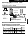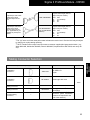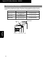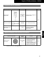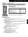
1
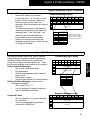
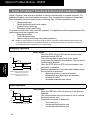
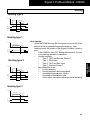
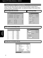
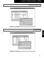
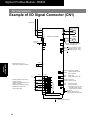
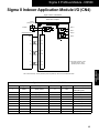
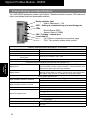
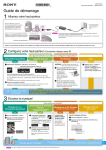
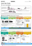
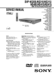
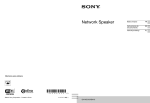
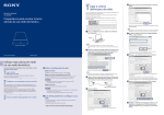
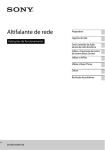
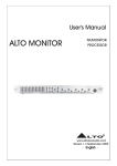
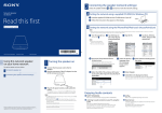
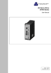
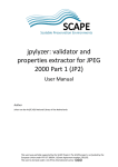
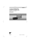
Sigma II Profibus Module - NS500 SIGMA II - Profibus DP¥ Connectivity for Single-Axis Positioning Used for a wide variety of applications, including: • • • Point-to-Point Positioning Precise Velocity Control Conditional Profile Execution in response to an external input For Additional Information . 40 Profibus DP™ Communication 42 Functional Features and Capabilities 46 Software Utility I/O Connections 48 50 Indexer Ratings and Specifications 51 Indexer Selection/Ordering Information 75 Indexer Application Module Dimensions Servomotor and Amplifier Ratings & Selections *Sigma II Servo System Product Catalog Supplement G-MI#99001x-Sigma II Page(s) - 41 45 47 49 * 55 82 For more information about Profibus¥, visit www.profibus.com 1. 2. 3. 4. 5. Simplified Control System • Conformance Tested Profibus DP¥ (EN50170), Device type: Generic I/O • Supports Profibus¥ cyclic data transfer • Baud Rates: Autobaud detect sets the application module speed to 9600bps to 12Mbps Easy to Set Up and Use • Just snap the JUSP-NS500 application module onto any Sigma II SGDH servo amplifier • No programming required: Configure with Profibus¥ conformance tested GSD file Various Motion Control Functions • Point table positioning • Edit up to 50 positions and corresponding speeds to the NS500’s set of parameters via either Profibus¥ or Yaskawa’s NSXXX pc setup utility • External input positioning • Station number input (indexing a rotary table) • Positioning moves with up to 16 stages of speed changes • Homing: choice of four styles Applications • Semiconductor fabrication, test, and assembly equipment • Food processing and packaging • Pharmaceutical packaging and test equipment • Automotive assembly and test equipment • Material handling, pick and place, linear motor • Machine tool (tool changers, sheet feeders, etc.) Certified International Standards • UL, cUL recognized (File #: E165827), CE compliance 39 JUSP-NS500 Indexer Design Features Sigma II Profibus Module - NS500 Sigma II Profibus Communication The Sigma II Indexer is a compact, cost-effective solution for the needs of both the machine OEM and the end user. All servo loops and positioning functions are included in a self-contained servo amplifier/indexer package. Machine controller to servo axis interfacing simplifies to Profibus DP¥ communications and wiring. Control System Architecture I/O FIELDBUS Master Module PLC or PC Actual Position, Speed Position, Speed, Acceleration, Deceleration Data transfer I/O connection SGDH- YASKAWA Servo amplifier slave Inverter Profibus Protocol • The Profibus DP¥ specification divides network transmissions into three phases: • Parameterization: specifies DP services. • Configuration: the master transfers application setup files to each node. • Data transfer: cyclic data exchange • Data transfer communication messages are suitable for time-critical, control-oriented data. • The Sigma II messages are eight bytes long, embedded within the data unit of the Profibus¥ FDL Frame Format. Profibus¥ FDL Frame Overview Profibus¥ FDL Frame Format JUSP-NS500 Indexer SD DA/SA FC DATA UNIT FCS ED FDL Telegram Where: SD = Start Delimiter Data Link DA SA = Source Address FC DATA_UNIT=Data Field Length FCS ED = End Diameter CRC = Cyclic Redundancy Code = Destination Address = Function Code = Frame Check Sequence Using the Eight-Byte Data Field • Sigma II with Profibus¥ accepts two types of messages in the Data Unit Field for positioning applications: • Move commands (monitor and control) • Set/Read commands (setup and troubleshooting) Sigma II Move Commands Command Message Format Byte Bit 7 0 1 2 3 4 5 6 7 0 Bit 6 Bit 5 Bit 4 Bit 3 Bit 2 Bit 1 Bit 0 0 ALRST ESTP 0 0 SVON C_STRT Response type Command code HOME PTBL STN STEP FEED 0 HOLD CANCEL 0 0 0 0 0 0 DIR INC Command data Refer to the Profibus¥ Interface Unit User’s Manual (SIE-C718-8) for a detailed description of the command bits. 40 Using move command messages • Initiate positioning or speed control moves • Communicate positioning move variables • Activate point tables of index moves • Activate homing, alarm reset, emergency stop, feed hold, and servo amplifier functions • Example of Command Execution: • Set the positioning command code and data • Change the Command Start(C-Start), byte 0, bit 0, from 0 to 1 Positioning Command Codes 0000 0001 0010 0011 0100 Operation No operation Simple positioning External positioning Positioning with notch signal outputs Multi-speed positioning Sigma II Profibus Module - NS500 Sigma II Responses to Move Commands Response Messages • Reports the status of the current positioning move , i.e., in position, near position, home, overtravel, alarm, etc. • Move data can be collected in the response. See the response type table at the right. • The data requirements in the response message are specified in the command message, byte 1, bits 4 through 7, (as shown on the Command Message Format table on the previous page). • Response codes are returned in the response message (byte 1, bits 4 through 7) along with the data. Response Message Format Byte Bit 7 0 1 2 3 4 5 6 7 0 Bit 6 Bit 5 Bit 4 Bit 3 Bit 2 Bit 1 Bit 0 READY PWRON ESTP_R ALRM WARN SVON_R C_STRT_R Response type Command code HOME_R PTBL_R STN_R STEP_R FEED_R 0 HOLD_R PRGS POT NOT INPOS NEAR HOME_P 0 DIR_R INC_R Response data Response Data Reference Units (RU) Response Type 0000 0001 0010 0011 0100 0101 1010 1011 Command position (RU) Current position (RU) Following error (RU) Command speed (1000RU/ min.) Current speed (1000RU/min.) Torque (%) Station number Point table number Refer to the Profibus DP¥ Interface Unit User’s Manual (SIE-C718-8) for a detailed description of the status bits. Sigma II Set/Read Commands and Command Codes Command Message Format Byte Bit 7 0 1 2 3 4 5 6 7 Bit 6 Bit 5 1 0 Bit 4 Bit 3 Bit 2 Bit 1 Bit 0 ALRST ESTP 0 0 0 SVON C_STRT Command code JUSP-NS500 Indexer Set/Read messages enable user friendly network routines that can reconfigure machine positioning variables, initialize setup routines, enable autotuning, source alarm and warning data, etc. These functions are available to any master on the network. Uses of Set/Read Messages • Set up and configuration data • Edit parameters • Set/edit preprogrammed point tables of index moves • Report alarm codes • Use with data transfer I/O communication Defining Set/Read Messages (versus move command messages) • Set by byte 0, bit 7 = 1 • It is not necessary to specify response type for Set/Read commands Command number Command message Command Code 0000 1000 1001 1010 1011 1100 1110 Operation No operation Read parameter Write parameter Set current position Set zero point Read alarm Reset Unit Response Message Format Command Codes • Set "No Operation" to prevent execution of commands. • Out-of-range parameters generate a setting error (WARN bit) Byte Bit 7 0 1 2 3 4 5 6 7 1 Bit 6 Bit 5 Bit 4 READY PWRON ESTP_R 0 Bit 3 ALRM Bit 2 Bit 1 Bit 0 WARN SVON_R C_STRT_R Command code Command number response data 41 Sigma II Profibus Module - NS500 Sigma II Profibus¥ Functional Features and Capabilities Sigma II Profibus¥acts as a servo position or velocity controller slave to a master controller. For application flexibility, use a data transfer connection from the applications software to dynamically load incremental or absolute point-to-point positioning data. For these applications use: • Simple positioning • Simple positioning with notch outputs • External input positioning • Multistage velocity positioning For precise velocity control only, use Feed operation. For applications where the parameters of the positioning moves can be preset, use: • Stepping operation • Point-table positioning • Station number positioning (rotary table operation) Note: Establish or change parameters of a preset move with an GSD file configuration, Yaskawa’s Windows NSXXX software utility, or a dynamic Sigma II data transfer of Set/Read Commands. For more permanent settings, recycle the power or issue a unit reset command (to move the parameters into non-volatile memory). Stepping Operation Velocity v Step distance Step distance Time JUSP-NS500 Indexer STEP DIR STEP bit: Refer to the Move Command message format, byte 2, bit 4. DIR bit: Refer to the Move Command message format, byte 3, bit 1. How it works: • When the STEP bit turns ON, the axis moves in the specified direction (DIR bit). • Use command data to select one of four preset parameters that define the step distance. Moves can be incremental or absolute. • When the STEP bit turns OFF during movement, step movement is cancelled. • Additional parameters to help define the stepping operation are preset to determine: • Approach velocity (v) and acceleration/ deceleration type (eight types are available, including S-curve) • Acceleration/deceleration values Feed Operation Velocity v Time FEED DIR FEED bit: Refer to the Move Command message format, byte 3, bit 3. 42 How it works: • While the FEED bit is ON, the axis jogs in the direction specified. • Use command data during movement to set or override the preset velocity feed. • Parameters are preset to determine: • Feed velocity (v) • Acceleration/deceleration type • Acceleration/deceleration rate Sigma II Profibus Module - NS500 Point Table Positioning PRESET INDEX MOVES How it works: • Use command data to select point table number and then the PTN bit to initiate positioning. • Fifty positioning points are available. • Point table parameters are preset to determine: • Target position • Positioning velocity POINT TABLE NUMBER TARGET POSITION POSITIONING VELOCITY 1 : 50 X1 — X50 V1 — V50 Velocity Time PTN PTN bit: Refer to the Move Command message format, byte 2, bit 6. Simple Positioning Velocity Movement distance Time C_STRT C-STRT bit: Refer to the Move Command message format, byte 0, bit 0. * Refer to the Move Command Message Format on page 40. Positioning with Notch/Zone (PLS) Outputs How it works: • Use the same procedure as simple positioning, except the positioning command code is to 0011. • Two settable notch signal outputs are available. • Notch signal output ON and OFF positions can be incremental or absolute. Velocity Notch signal output position Time C_STRT Output NOTCH1 Output NOTCH2 External Input Positioning How it works: • Use the same procedure as simple positioning, except the positioning command code is 0010. • When the EXTP (external input signal) is activated during a move, the system will perform the final positioning. • Parameters determine: • External positioning distance • External positioning velocity Velocity External positioning movement distance Time C_STRT Input EXTP 43 JUSP-NS500 Indexer How it works: • Use simple positioning to receive target position data from a Profibus¥ master controller’s application software. • When the C_STRT bit turns ON, the system moves from the current position to the target position. • Communicate target positions with a move command message* using the positioning command code (set to 0001) and command data set with the target position. • Velocity, acceleration type, and acceleration rate work the same way as in stepping operation. Sigma II Profibus Module - NS500 Multi-Stage Velocity Positioning Velocity Step2 Step1 Time C_STRT C_STRT bit: Refer to the Move Command message format, byte 0, bit 0. How it works: • Use the same procedure as simple positioning, except the positioning command code is 0100. • During axis movement, after reaching the parameter’s initial target position, the axis switches to the next speed and moves to the position specified in the next step. • A maximum of 16 steps are available. • Parameters set: • The number of steps • Reference velocity • Acceleration/deceleration Station Number Positioning 1 2 8 3 7 JUSP-NS500 Indexer 4 6 5 Velocity Time STN DIR STN bit: Refer to the Move Command message format, byte 2, bit 5. 44 How it works: • The system will index to the prescribed station number when the STN command bit is turned ON. The target station is defined with command data in the move command message (refer to page 36). • Define (by parameter) up to 32,767 equidistant stations per rotation. • Set the direction of rotation with the DIR bit or set the system (by a parameter) to automatically select the shortest distance. • Set acceleration and deceleration with parameters. • Accommodate rotary systems with gearing or belt ratios with parameters for electronic gear ratios. Sigma II Profibus Module - NS500 Homing Homing type 0 Velocity approach speed creep speed Time HOME Encoder Phase C DEC Velocity approach speed creep speed Time HOME Zero Input Homing type 2 Velocity approach speed creep speed Time HOME Zero Input DEC How it works: When the HOME bit turns ON, the system returns to the home position at the programmed speed and direction. After reaching home, the position of the Sigma II Profibus¥resets to zero. • If the HOME bit turns OFF during the procedure, the rest of the homing operation is cancelled. • Homing methods: • Type 0: DEC and Encoder Phase C • Type 1: Zero Input • Type 2: DEC and Zero Input • Type 3: Encoder Phase C • Use parameters to set: • Homing direction • Homing approach and creep speed • Acceleration/deceleration velocity • Acceleration/deceleration type • Home offset (zero-point return final travel distance). Homing type 3 Velocity approach speed creep speed Time HOME Encoder Phase C 45 JUSP-NS500 Indexer Homing type 1 Sigma II Profibus Module - NS500 Sigma II Profibus¥ Software Utility The Electronic Data Sheet (GSD) file is the recommended setup utility to configure Sigma II Profibus¥from the networksoftware manager. Use Yaskawa’s NSXXX software for local setup of the Sigma II Profibus¥ via personal computer. The following are examples of this software and the utilities available through the GSD file. Monitoring/Setup Software Point Table Positioning Setup JUSP-NS500 Indexer Settings and Parameters Editing 46 Positioning Setup Sigma II Profibus Module - NS500 Overtravel Configuration JUSP-NS500 Indexer Homing Setup 47 Sigma II Profibus Module - NS500 I/O Connections Example of I/O Signal Connector (CN1) Main Power 1MC V W L1C L2C 1 2 Be sure to ground Optical encoder SGDH Servo Amplifier 1CN 37 ALO1 Alarm code maximum output: Operating voltage: 30VDC ALO3 Operating current: 20mADC 39 ALO3 38 BAT (+) 21 JUSP-NS500 Indexer Backup battery 2.8 to 4.5V (When using an absolute encoder) P BAT (-) 22 25 26 +24VIN +24V Home position signal Be sure to properly prepare the end of the shielded wire. 1CN 6 Optional Home position near PG 2CN FG 10 External positioning move function Positive overtravel (Forward run prohibited when OFF) Negative overtravel (Reverse run prohibited when OFF) A (1)Servomotor B (2) M C (3) D (4) U L1 L2 + 47 3.3k: 27 28 40 - /EXT1 44 P-OT 42 N-OT 43 /DEC 41 /EXT2 45 /COIN+ Positioning completed (ON when positioning has /COINbeen completed) /BK+ Brake output /BK- (Brake released when ON) 29 /S-RDY+ Servo ready 30 /S-RDY- (ON when ready) 31 ALM+ 32 ALM- 3CN 46 Servo alarm output (OFF with an alarm) Photocoupler maximum output: Operating voltage: 30VDC Operating current: 50mADC Sigma Win (Used for data tracing and highly accurate auto-tuning only). CN10 Dual Port RAM Sigma II Indexer JUSP-NS500 P: Indicates twisted wire pairs. 48 Sigma II Profibus Module - NS500 Sigma II Indexer Application Module I/O (CN4) Sigma II Indexer JUSP-NS500 SGDH Servo Amplifier 24VDC (sinking or sourcing) CN10 Dual Port RAM 4CN 11 EmSTOP 9 Optional External PG* A 16 PA /A 17 /PA B 18 PB /B 19 /PB C 14 PC /C 15 /PC Notch 1+ 13 Notch 1- 10 Notch 2+ 20 Notch 2- Photocoupler maximum output: Operating voltage: 30VDC Operating current: 50mADC JUSP-NS500 Indexer GND 1, 2, PG 0V 3 12 *Use for "Full Closed Loop " function (alternative position loop feedback). Refer to the User’s Manual for details. Sigma II Indexer with Profibus¥ JUSP-NS500 Pin Number Signal Description Pin Number Signal 1 PG0V signal ground 11 +24V 2 PG0V signal ground 12 NOTCH1+ 24V shared terminal for external inputs Notch output 1 3 4 PG0V — signal ground — 13 14 NOTCH1PC Phase C input 5 6 — — — — 15 16 /PC PA Phase B input 7 8 — — — — 17 18 /PA PB Phase A input 9 EMSTOP 19 /PB 10 NOTCH2+ 20 NOTCH2- Description — — — — Notch output 2 49 Sigma II Profibus Module - NS500 Indexer Ratings and Specifications The JUSP-NS500 application module uses Profibus¥Standard network connector, LED status indicators, and address and baud rate settable switches. Rotary switches (two) • Station Addresses 0 - 126 CN11: Setting up, commissioning, and monitoring port LEDs • Module Status (ERR) • Network Status (COMM) CN6: Profibus¥network port Local node I/O • CN1 (Refer to connections on previous page) • CN4: Two optically isolated notch outputs Profibus¥Application Module Specifications: JUSP-NS500 Power Supply Method Power Consumption Consumption Current External Dimensions (w, h, d) inches (mm) Approximate Mass in lb. (kg) Supplied from the SGDH power supply. 1.3W 250mA 0.79 u 5.59 u 5.04 (20 u 142 u 128) 0.441 (0.2) Local Node Inputs and Outputs (Combined with the Amplifier’s I/O) JUSP-NS500 Indexer Digital Inputs Digital Outputs Six optically isolated 24VDC inputs: Emergency Stop (E Stop), latch, home near (DEC) switch, forward overtravel, reverse overtravel, and inputs for an optional full closed loop feedback. Ten optically isolated 24VDC outputs: alarm out, servo-ready, servo warning, holding brake, in-position, 3 alarm codes, and 2 notch settable outputs. Also included: a scalable encoder position output. Servo System Specifications Motor feedback resolution / standard Motor feedback resolution / optional Linear motor feedback resolution / standard Choice of Amplifier sizes 13-bit incremental encoder (8,192PPR) for motors below 1hp 17-bit incremental encoder (16,384PPR) for motors above 1hp 16-bit absolute encoder for motors below 1hp 17-bit incremental/absolute for motors above 1hp 0.078 micron (using 20 micron linear scale pitch) 115 Vac single-phase, 30 to 200W 230 Vac single-phase, 30W to 1.5kW 230 Vac three-phase, 500W to 15kW 480 Vac three-phase, 500W to 15kW Environmental Ambient/Storage Temperature Global Safety Certifications 50 0° to 55°C / -20° to 85°C UL, CUL, CE, TUV Sigma II Profibus Module - NS500 Selecting Your Sigma II Indexer System Specify part number JUSP-NS500, the indexer add-on application module. Use the tables beginning on the following page to specify choice of indexer interface cables, mating connectors only, set-up and monitoring tools, and software. System Configuration Setup and mounting software (B) SGDH Amplifier Sigma II Application Module NSXXX x11CN setup software mating connector or cable xProfibus¥ network connector GSD Software File x1CN I/O cable or connector x4CN I/O cable or connector (A) Sigma II servomotor, linear motor, or direct drive motor. Power Components (E) Additional regeneration resistor capacity (if necessary), optional DC reactor, etc. (C) Pre-wired power and feedback cables or Profibus¥ Interface Unit Users Manual: SIE-C718-8 Linear Motor Users Manual: YEA-SIA-S800-39.11 (Manual provided at no charge with a purchase order, but must be requested). Power Components (motor, amplifier, and connections for power and feedback) Select the required power components (servomotor, power and feedback connectors or pre-wired cables, amplifier, regenerative packs, etc.) from the following catalog pages. Use this table or the Yaskawa publications referenced below to determine which catalog section describes the best servomotor for the application. Application Requirements (Maximum) Speed (rpm) 5000 5000 3000 5000 3000 5000 6000 2000 System Voltage and Sigma II Servomotor Series Number Selection Guide for Power Components 100Vac 200Vac 200Vac 480Vac Rated Torque Peak Torque of Motor Page Number * oz • in [lb • in] oz • in [lb • in] Sizes Single-phase Single-phase Three-phase Three-phase 338 676 [845] [140] [845] [140] [43] [1240] 1010 2027 [1988] [422] [1988] [422] [190] [6120] 6 5 10 6 10 6 2 5 SGMAH SGMPH — — — — — — SGMAH SGMPH — — — — — — — — SGMGH SGMSH — — — — — — — — SGMGH SGMSH SGMUH SGMBH 11 29 57 85 127 139 139 165 * Yaskawa publication: Sigma II Servo System Product Catalog Supplement G-MI#99001x-Sigma II, Linear Motor Catalog KAE-S800-39.10, Direct Drive Motor Catalog YEA-KAA-DDM-1. 51 JUSP-NS500 Indexer Specify a technical manual, if it is needed, on your servo system purchase order: (D) Connector kits for local cable assembly Sigma II Profibus Module - NS500 Sigma II Indexer Selection Use the servomotor and amplifier selection of this catalog for specification and selection of Sigma II servomotor and servo amplifier. Component Description Sigma II Add-on Indexer Application Module Part Number Comments Item Class JUSP-NS500 Mounting hardware requirements: one ground strap mounting screw. (See supplementary information on the next page.) Stock Use the Sigma II Application Module Mounting Dimensions on pages 75 to 82 for determining overall indexer panel space requirements. For 480VAC large capacity amplifiers (22 - 55kW), refer to the Sigma II catalog for amp dimensions. Indexer I/O Interface Cable Selection Component Description (E) Input/Output 1CN Cable & Transition Terminal Block JUSP-NS500 Indexer Input/Output 1CN Cable with Pigtail Leads Input/Output 4CN Cable with Pigtail Leads 52 Part Number Comments JUSP-TA50P 35mm DIN rail mountable; the cable length is 0.5m. JZSP-CKI01-(A)* Use the following key to specify required cable length (last digit of the part number): 1: 1m (standard) 2: 2m 3: 3m CKI-NS300- Use the following key to specify required cable length (last two digits of the part number): 01: 1m (standard) 02: 2m 03: 3m Item Class Stock Sigma II Profibus Module - NS500 Use the following key to specify required cable length (last two digits of the part number): Input/Output 1CN Cable Cable with Female D-Sub output Connector* JZSP-CKI0D-** Input/Output 1CN+4CN Cable with Female D-Sub output Connector* Applicable only for SGDH-1E (15 kW) and below. CKI-NS300D-** (for use with NS500 Indexer) D50: 01: 02: 03: 0.5m 1m (standard) 2m 3m Use the following key to specify required cable length (last two digits of the part number): D50: 01: 02: 03: 0.5m 1m (standard) 2m 3m * The “(A)” at the end of the cable part number indicates the revision level. Revision level may be subject to change prior to this catalog reprinting. ** 50 Pin Female D-Sub output connector mates to customer supplied third party terminal block. (e.g., Wago #289-449, Weidmuller #919658, Phoenix #2283647, Amphenol/Sine #20-51039, and many others). Component Description (E) Part Number 1CN Mating Connector JZSP-CKI9 4CN Mating Connector DE-9406973 Comments Item Class for SGDH I/O 50-pin Solder type with cover Stock 3CN Peripheral Mating Connector — YSC-1 CN11 Setup Software Mating Connector — DE9404559 Profibus Mating Connector — — Strongly advised: YS-16 cable (next page) Standard 9-pin male D-Sub connector. (Note: termination resistors are required for the end of the network.) 53 JUSP-NS500 Indexer Mating Connector Selection Sigma II Profibus Module - NS500 Supplementary Information For grounding, connect the ground wire of the Sigma II Indexer application module to the point marked "G" on the SGDH servo amplifier. Refer to the following table for the proper screw size. Servo Amplifier "G" Screw M3 x 10 (round head phillips with split lock washer and flat washer M4 x 10 (round head phillips with split lock washer and flat washer M4 x 8 (round head phillips with split lock washer and flat washer SGDH-A3-02BE SGDH-A3-10AE SGDH-15-50AE SGDH-15-50DE SGDH-60-1EAE SGDH-60-1EDE SERVOPACK SGDH- NS600 MODE/SET JUSP-NS500 Indexer POWER Example: For SGDH (30W to 5.0kW) 54 One supplied with NS500 One supplied with NS500 One supplied with NS500 Use front panel side screw hole. GROUND WIRE "G" CHANGE Comments Sigma II Profibus Module - NS500 Peripheral Device Selection Component Description (E) Hand-held Digital Operator Panel Part Number Comments JUSP-OP02A-1 and JZSP-CMS00-1 Portable unit with 1m adapter cable for Sigma II Indexer Item Class Stock Setup Software Interface Cable for CN10 JZSP-BA01 — YS-16 3.6V, 1000mAh (lithium battery) Pre-wired 1.5m cable with 9-pin connector (RS232) for NSXXX software Sigma II Network Tools and Documentation Component Description (E) Publication Number* Comments Item Class • Yaskawa’s NSXXX monitoring and set-up software for Windows 95, Windows 98, and Windows NT. • Electronic Data Sheet (GSD) software for Profibus¥ configuration software manager. • NS500 User’s Manual.pdf. Stock Includes : Fieldbus Tools and documentation* YEA-CD-S80034.1 *Available by request. Contact: [email protected]. 55 JUSP-NS500 Indexer Absolute Encoder Battery Sigma II Profibus Module - NS500 NOTES JUSP-NS500 Indexer 56 Sigma II Application Modules Dimensions in inches (mm) SGDH-A3AE to -02AE (200V Single-phase, 30 to 200W) and SGDH-A3BE to -01BE (100V Single-phase, 30 to 100W) SERVOPACK SGDH YASKAWA 88888 MODE/SET DATA/ CHARGE POWER C N 3 L2 1 A 6.30 (160) L1 2 L1C C N 1 L2C B1 B2 U V 2.17 (55) C B C N 2 W 2.95 (75) D 5.12 (130) 2 x M4 screw holes 5.89 (149.5) ±0.020 (0.5) (Mounting pitch) 0.22 (5.5) Mounting Hole Diagram 0.20 (5) • • Sigma II Modules SGDH Servo Amplifier/Application Modules Part Number JUSP-NS100 JUSP-NS300 JUSP-NS310 JUSP-NS500 JUSP-NS600 JUSP-FC100 MP940 * ** *** 0.67 (17) 0.20 1.97 (50) (5) SGDH Option Description Mechatrolink Indexer with DeviceNet¥ Indexer with DeviceNet¥ Profibus Indexer Full Closed Loop Single Axis Control A B 5.59 (142) 0.35 (9) 5.67 (144) 0.32 (8) 5.59 (142) 0.35 (9) C 0.79 (20) D Approximate Mass** lb (kg) 5.08 (129) 0.44 (0.2) 5.24 (133)** 0.7 (0.32) 5.08 (129) 1.22 (31)*** 0.44 (0.2) 0.89 (0.40) Option card only. Add 0.75in (19mm) to front end of card for micro connector. Add approx. 0.75in (19mm) for optional back-up battery. 75 Sigma II Application Modules • • • SGDH-04AE (200V Single-phase, 400W), SGDH-02BE (100V Single-phase, 200W) and SGDH-04FE (100V Single-phase, 400W) Sigma II Modules SERVOPACK SGDH YASKAWA 88888 MODE/SET DATA/ POWER C N 3 L1 L2 1 2 L1C A 6.30 (160) CHARGE C N 1 L2C B1 B2 U V C N 2 2.95 (75) C B W D 2.95 (75) 5.12 (130) 2 x M4 screw holes 0.20 (5) 5.89 (149.5) ±0.020 (0.5) (Mounting pitch) 0.22 (5.5) Mounting Hole Diagram Part Number JUSP-NS100 JUSP-NS300 JUSP-NS310 JUSP-NS500 JUSP-NS600 JUSP-FC100 MP940 * ** *** 76 0.47 12) 0.67 (17) 2.48 (63) SGDH Option Description Mechatrolink Indexer with DeviceNet¥ Indexer with DeviceNet¥ Profibus Indexer Full Closed Loop Single Axis Control A B 5.59 (142) 0.35 (9) 5.67 (144) 0.32 (8) 5.59 (142) 0.35 (9) Option card only. Add 0.75in (19mm) to front end of card for micro connector. Add approx. 0.75in (19mm) for optional back-up battery. C 0.79 (20) D Approximate Mass** lb (kg) 5.08 (129) 0.44 (0.2) 5.24 (133)** 0.7 (0.32) 5.08 (129) 1.22 (31)*** 0.44 (0.2) 0.89 (0.40) Sigma II Application Modules Sigma II Modules SGDH-05AE to -10AE (200V Three-phase, 0.5 to 1.0kW) SGDH-08AE-S (200V* Single-phase, 750W) 2-)0.20 ()5) holes YASKAWA SERVOPACK SGDH— 88888 MODE/SET DATA/ CHARGE POWER 6.30 (160) L1 C N 3 L2 L3 2 A 1 C N 1 L1C L2C B1 B2 B3 T V C N 2 C 2 2.95 (75) W C D B U 2.95 (75) 5.12 (130) 2 x M4 screw holes 5.89 (149.5) ±0.020 (0.5) (Mounting pitch) 0.22 (5.5) Mounting Hole Diagram 0.20 (5) • • Part Number JUSP-NS100 JUSP-NS300 JUSP-NS310 JUSP-NS500 JUSP-NS600 JUSP-FC100 MP940 * ** *** 0.47 12) 0.67 (17) 2.48 (63) SGDH Option Description Mechatrolink Indexer with DeviceNet¥ Indexer with DeviceNet¥ Profibus Indexer Full Closed Loop Single Axis Control A B 5.59 (142) 0.35 (9) 5.67 (144) 0.32 (8) 5.59 (142) 0.35 (9) C 0.79 (20) D Approximate Mass* lb (kg) 5.08 (129) 0.44 (0.2) 5.24 (133)** 0.7 (0.32) 5.08 (129) 1.22 (31)*** 0.44 (0.2) 0.89 (0.40) Option card only. Add 0.75in (19mm) to front end of card for micro connector. Add approx. 0.75in (19mm) for optional back-up battery. * Rating 200 to 230Vac +10% -5% 77 Sigma II Application Modules • • SGDH-15AE (200V Three-phase, 1.5kW) SGDH-05DE (400V Three-phase, 0.5kW to 1.5kW) Sigma II Modules SGDH YASKAWA 88888 DATA/ 6.30 (160) MODE/SET CHARGE L1 POWER C N 3 L2 1 2 L1C C N 1 L2C B1 B2 U V C N 2 4.33 (110) C D 7.09 (180) B W 2.95 (75) 0.20 (5) Part Number JUSP-NS100 JUSP-NS300 JUSP-NS310 JUSP-NS500 JUSP-NS600 JUSP-FC100 MP940 * ** *** 78 2 x M4 screw holes (Mounting pitch) 0.20 (5) 5.89 (149.5) ±0.020 (0.5) 0.22 (5.5) Mounting Hole Diagram Cooling fan 3.94 (100) ±0.020 (0.5) (Mounting pitch) 0.20 (5) SGDH Option Description Mechatrolink Indexer with DeviceNet¥ Indexer with DeviceNet¥ Profibus Indexer Full Closed Loop Single Axis Control A B 5.59 (142) 0.35 (9) 5.67 (144) 0.32 (8) 5.59 (142) 0.35 (9) Option card only. Add 0.75in (19mm) to front end of card for micro connector. Add approx. 0.75in (19mm) for optional back-up battery. C 0.79 (20) D Approximate Mass** lb (kg) 5.08 (129) 0.44 (0.2) 5.24 (133)** 0.7 (0.32) 5.08 (129) 1.22 (31)*** 0.44 (0.2) 0.89 (0.40) Sigma II Application Modules SGDH-20AE, 30AE (200V Three-phase, 2.0kW, 3.0kW) SGDH-15AE-S (200V Single-phase, 1.5 kW)* SGDH-20DE, 30DE (400V Three-phase, 2.0kW, 3.0kW) YASKAWA SERVOPACK Sigma II Modules SGDH 88888 2-)0.24 ()6) holes MODE/SET CHARGE DATA/ POWER CN3 9.84 (250) CN1 CN2 C B2 B B3 U V W 4.33 (110) D 2.95 (75) 7.09 (180) 4 x M5 screw holes (Mounting pitch) 9.39 (238.5) ±0.020 (0.5) 0.24 (6) Mounting Hole Diagram 0.22 (5.5) • • • (100°) 1.57 (40) 3.94 (100) 0.20 (5) ±0.020 (0.5) (Mounting pitch) Part Number JUSP-NS100 JUSP-NS300 JUSP-NS310 JUSP-NS500 JUSP-NS600 JUSP-FC100 MP940 * ** *** SGDHG Option Description Mechatrolink Indexer with DeviceNet¥ Indexer with DeviceNet¥ Profibus Indexer Full Closed Loop Single Axis Control Cooling fan 0.20 (5) A B 5.59 (142) 3.9 (99) 5.67 (144) 3.86 (98) 5.59 (142) 3.9 (99) C 0.79 (20) D Approximate Mass** lb (kg) 5.08 (129) 0.44 (0.2) 5.24 (133)** 0.7 (0.32) 5.08 (129) 1.22 (31)*** 0.44 (0.2) 0.89 (0.40) Option card only. Add 0.75in (19mm) to front end of card for micro connector. Add approx. 0.75in (19mm) for optional back-up battery. * Rating: 200 to 230Vac +10%, -5% 79 Sigma II Application Modules • • SGDH-50AE (200V Three-phase, 5.0kW) SGDH-50DE (400V Three-phase, 5.0kW to 1.5kW) 2 )0.24 ()6) hole YASKAWA SERVOPACK 200V SGDH-50AE Sigma II Modules Ver. L1 L2 MODE/SET DATA/ CHARGE POWER L3 C N 3 A 1 2 9.84 (250) C N 1 L1C L2C C N 2 B1 B1 B1 C V B U W D 5.31 (135) 2.95 (75) 9.06 (230) Mounting Hole Diagram 9.39 (238.5) ±0.020 (0.5) Mounting pitch 0.24 (6) 4 x M5 screw holes (10 0°) 0.22 (5.5) 3.27 (8.3) 0.20 (5) Part Number JUSP-NS100 JUSP-NS300 JUSP-NS310 JUSP-NS500 JUSP-NS600 JUSP-FC100 MP940 ** ** *** 80 4.92 (125) (Mounting pitch) Description Mechatrolink Indexer with DeviceNet¥ Indexer with DeviceNet¥ Profibus Indexer Full Closed Loop Single Axis Control 0.20 (5) A B 5.59 (142) 3.9 (99) 5.67 (144) 3.86 (98) 5.59 (142) 3.9 (99) Option card only. Add 0.75in (19mm) to front end of card for micro connector. Add approx. 0.75in (19mm) for optional back-up battery. C 0.79 (20) D Approximate Mass** lb (kg) 5.08 (129) 0.44 (0.2) 5.24 (133)** 0.7 (0.32) 5.08 (129) 1.22 (31)*** 0.44 (0.2) 0.89 (0.40) Sigma II Application Modules SGDH-60AE, SGDH-75AE (200V Three-phase, 6.0kW, 7.5kW) SGDH-60DE, SGDH-75DE (400V Three-phase, 6.0kW, 7.5kW) Sigma II Modules SERVOPACK 200V SGDHVer. CN8 CN5 A maximum 13.78 (350) CN3 CN2 CN1 B C L1 L2 L3 + - B1 B2 U V W D maximum 9.06 (230) 9.25 (235) View A 0.30 (7.5) Mounting Hole Diagram 3.54 (90) 13.19 (335) (Mounting pitch) 5.71 (145) 4 x M5 screw holes View A 0.30 (7.5) • • Part Number JUSP-NS100 JUSP-NS300 JUSP-NS310 JUSP-NS500 JUSP-NS600 JUSP-FC100 MP940 * ** *** 0.98 (25) 7.09 (180) (Mounting pitch) SGDH Option Description Mechatrolink Indexer with DeviceNet¥ Indexer with DeviceNet¥ Profibus Indexer Full Closed Loop Single Axis Control 0.98 (25) A B 5.59 (142) 4.5 (114.5) 5.67 (144) 4.47 (113.5) 5.59 (142) 4.5 (114.5) C 0.79 (20) D Approximate Mass* lb (kg) 5.08 (129) 0.44 (0.2) 5.24 (133)** 0.7 (0.32) 5.08 (129) 1.22 (31)*** 0.44 (0.2) 0.89 (0.40) Option card only. Add 0.75in (19mm) to front end of card for micro connector. Add approx. 0.75in (19mm) for optional back-up battery. 81 Sigma II Application Modules • • SGDH-1AAE, SGDH-1EAE (200V Three-phase, 11.0kW, 15.0kW) SGDH-1ADE, SGDH-1EDE (400V Three-phase, 11.0kW, 15.0kW) Cooling fan Air flow Sigma II Modules SERVOPACK 200V SGDH— Ver. YASKAWA 5.51 (140) CN3 maximum 17.72 (450) 8. 8. 8. 8. 8. A DATA CN1 CN2 B C L1 L2 L3 B1 B2 +1 +2 U V W 10.55 (268) D 11.12 (285) 0.295 (7.5) View A Mounting Hole Diagram 0.295 (7.5) 17.13 (435) 5.59 (142) 8.23 (209) 8.74 (2.22) 10.67 (271) View A: Part Number JUSP-NS100 JUSP-NS300 JUSP-NS310 JUSP-NS500 JUSP-NS600 JUSP-FC100 MP940 * ** *** 82 1.18 0.28 (7) (30) 7.87 (200) SGDH Option Description Mechatrolink Indexer with DeviceNet¥ Indexer with DeviceNet¥ Profibus Indexer Full Closed Loop Single Axis Control 1.18 (30) A B 5.59 (142) 4.5 (114.5) 5.67 (144) 4.47 (113.5) 5.59 (142) 4.5 (114.5) Option card only. Add 0.75in (19mm) to front end of card for micro connector. Add approx. 0.75in (19mm) for optional back-up battery. C 0.79 (20) D Approximate Mass* lb (kg) 5.08 (129) 0.44 (0.2) 5.24 (133)** 0.7 (0.32) 5.08 (129) 1.22 (31)*** 0.44 (0.2) 0.89 (0.40) Sigma II Indexer Application Modules Yaskawa . . . A World of Automation Solutions Yaskawa Electric America, Inc. Chicago-Corporate Headquarters 2121 Norman Drive South Waukegan, Illinois 60085 1-800-YASKAWA http://www.yaskawa.com Yaskawa Electric America, Inc. November 2003 Yaskawa Electric Europe Am Kronberger Hang 2, 65824 Schwalbach, Germany 49-6196-569-300 http://www.yaskawa.de Yaskawa Electric Corporation New Pier Takeshiba South Tower, 1-16-1 Kaigan Minatoku, Tokyo 105 Japan 81-3-5402-4511 http://www.yaskawa.co.jp G-MI#00008F Printed In U.S.A.