1
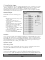
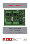
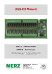
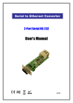
ELECTRONICS
The SPO-RL8 provides 8 relay and 4 optically isolated inputs for control and sensing applications. It is
controlled via a serial port using a set of simple text commands. Connection to the real world is via
“pluggable type” screw terminal blocks. Power can be supplied via a 9-12V DC power supply, such as
a wall adaptor rated at 500mA minimum. The SPO-RL8 comes with a simple Windows compatible
program to set the state of the relays and to display input status.
Specifications
Relays
•
•
•
8 Form C change-over relays
Contact rating resistive load – 15A 24VDC, 15A
120VAC, 10A 240VAC
Contact rating inductive load – 5A 24VDC, 5A 120VAC,
5A 240VAC
Isolated Inputs
•
•
•
•
4 isolated inputs
minimum voltage 5V DC (5mA)
maximum voltage 24V DC (25mA)
Isolation – 2500V peak, 1775 RMS (1 second)
General
•
•
•
•
•
Power 9-12V @ 500mA via 2.1mm DC power socket –
centre pin +ve
Data and Power LED’s
Dimensions – 140mm x 110mm x 35mm (excluded screw terminals)
Serial port – 3-way – pin 2→ pin 2, pin 3→ pin3, pin 5→ pin 5, maximum cable length >100m
Format - 9600 baud, 8 data, 1 stop, no parity –
Operation
There are 3 ways to communicate with the SPO-RL8 from your computer:
1. Using a terminal emulator program such as “Hyper Terminal”
2. The supplied Windows Program
3. Writing your own software.
Audon Electronics 123 High Road, Chilwell, Nottingham, NG9 4AT UK
Phone +44 (0)115 925 8412 Fax +44 (0) 115 925 9757 email [email protected]
Page 1
1. Terminal Emulator Program
If you are running Windows then one is supplied with the operating system. In Windows 3.1 it is called
“Terminal” and in Windows 95/98 it is called “HyperTerminal”. Of course there are a number of third
party terminal emulator programs that will work just as well. When using these programs the
communication parameters need to be set for 9600 baud, 8 data bits, 1 stop bit, no parity and no flow
control. Simply type the commands as detailed later.
2.Windows Program
The SPO-RL8 comes with a Windows program.
Features;
•
•
•
•
•
•
•
•
•
•
Manual control of each relay through use of
“Toggle” switch
Timer function - each relay can be
independently made to switch on or off at
timed periods
Unlimited on/off times can be programmed
Different times for each day if required
Time settings can be saved in a setup file
Virtual LED display of inputs
Inputs can be logged to a ASCII text data file
– view in Notepad or Excel
Adjustable log rate from 1 to 1000'
s seconds
For use with any COMM port
Compatible with Win 95/98/Me/2000/XP
Installation
Create a directory on your PC and copy all the files from the CD in the folder SPO-RL8 into it. Run the
program SPO_RL8.exe. The screen as shown above will be displayed, and the program will default to
using COMM port 1. To change to another COMM port, click on the “Hardware Configuration” button
at the top right of the window, or press the F6 function key. A window will appear with 3 Serial port
listings. You must change all 3 by clicking on the “Modify” button.
Operation - Outputs
Manual Relay operation
Move the mouse to a toggle switch and click. You will see the toggle switch change position, and the
corresponding LED will illuminate to indicate that the Relay has been activated.
Timed Operation
A timed weekly sequence can be set up for each relay. Double click on the grey Timer panel to bring
up the Timer window. NOTE – the toggle switch must be set to OFF for the timed output to work.
Audon Electronics 123 High Road, Chilwell, Nottingham, NG9 4AT UK
Phone +44 (0)115 925 8412 Fax +44 (0) 115 925 9757 email [email protected]
Page 2
Click the Add button to add a new on/off time. You can set the event day, time and whether the event is
an on or off event. The timed events are automatically listed in chronological order. Complete timed
sequences can be saved to a file by clicking on the “Save Settings” button on the main program
window. Likewise, previously stored sequences can be recalled by clicking on the “Load Setting”
button.
Operation – Inputs
The Software checks the status of the inputs twice a second, and illuminates an appropriate LED if an
input signal is detected. The software also includes a data logger, where the inputs are logged to a file
called “Digin.log” along with the date and time. This is an ASCII text file, which can be viewed in
Notepad or Excel (the file uses the “;” parameter separator character)
•
•
•
Start/Stop button – starts or stops data logging
Reset File – erases any existing data in Digin.log
Log Rate – enter a log rate value in seconds
3. Writing You Own Software
The supplied program is written using ProfiLab software package available form Audon Electronics.
This is a low cost graphical programming package aimed at non-programmers. A Demo version is
available on the supplied CD.
Visual Basic
A VB example is also included on the CD. The component Mscomm must be installed for this example
to work. Mscomm is freely available from the Microsoft web site.
Audon Electronics 123 High Road, Chilwell, Nottingham, NG9 4AT UK
Phone +44 (0)115 925 8412 Fax +44 (0) 115 925 9757 email [email protected]
Page 3
Commands
A set of simple text commands are used to control the relays, return their status or read the inputs. Each
command consists of a string of ASCII characters followed by carriage return (Enter ↵). The ‘#’
character is output as a prompt to indicate the SPO-RL8 is waiting for a command. Each character
received is echoed back. On completion of each command, good or bad, a carriage return/line feed
combination is output followed by the ‘#’ prompt. If the command or parameter is invalid, the
command is ignored and a ‘?’ is output before the next ‘#’ prompt.
Note:
• Commands are not processed until the carriage return character is received.
• Commands can be in upper or lower case.
• Relays are numbered 1 to 8. Relay number ‘0’ (zero) indicates ALL relays.
• Inputs are numbered 1 to 4. Input number ‘0’ (zero) indicates ALL inputs.
• Where a hex byte is used, each bit within the byte indicates its corresponding relay or input. Bit 0
indicates relay or input 1, bit 1 indicates relay or input 2, etc.
Nx – Turn a relay ON (where x = relay number)
Eg.
“N3” – turn on relay 3
“N0” – turn on ALL relays
Fx – Turn a relay OFF (where x = relay number)
Eg.
“F3” – turn off relay 3
“F0” – turn off ALL relays
Tx – TOGGLE a relay on/off (where x = relay number) Changes the state of a relay (ON to OFF,
OFF to ON)
Eg.
“T3” – toggle relay 3
“T0” – toggle ALL relays
Rhh – Set ALL relays directly “hh” is a hexadecimal byte. Each bit within the byte indicates whether
the corresponding relay is operated or not. If the bit is ‘1’ then the relay is operated, if the bit is ‘0’ then
the relay is released.
Eg.
“R55” – relays 1,3,5,7 ON, all others OFF
“R0F” – relays 1-4 ON, all others OFF
Sx – relay STATUS (where x = relay number) A ‘0’ (zero) is returned if the relay is released, ‘1’ if
operated. The command “S0” returns the status of ALL relays. In this case a hex byte is returned. Each
bit within the byte indicates the status of the corresponding relay.
Eg.
“S3” – returns the status of relay 3
“S0” – returns the status of ALL relays
Ix – INPUT status (where x = input number) A ‘1’ is returned if the input is enabled, ‘0’ otherwise.
The command “I0” returns the status of ALL inputs. As with the ‘S’ command, a hex byte is returned.
Bits 0-3 indicate the status of inputs 1-4. Bits 4-7 are unused and are set to ‘0’.
Eg.
“I1” – returns the status of input 1
“I0” – returns the status of ALL inputs
A special command, ‘?’, will print the software date.
Audon Electronics 123 High Road, Chilwell, Nottingham, NG9 4AT UK
Phone +44 (0)115 925 8412 Fax +44 (0) 115 925 9757 email [email protected]
Page 4