1
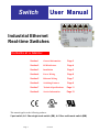
Instruction Manual
CI-ControlWave
Wave IES
Issue: 07/2001
TM
Industrial Ethernet Real-time Switches
5 Port Switch:
BB-GT-5ES-1
4+1 Fiber Single-mode Switch (SM): BB-GT-5ES-2CS
4+1 Fiber Multi-mode Switch (MM):
BB-GT-5ES-3SC
Bristol Babcock
NOTICE
Copyright Notice
The information in this document is subject to change without notice. Every effort has been
made to supply complete and accurate information. However, Bristol Babcock assumes no
responsibility for any errors that may appear in this document.
Request for Additional Instructions
Additional copies of instruction manuals may be ordered from the address below per
attention of the Sales Order Processing Department. List the instruction book numbers or
give complete model number, serial or software version number. Furnish a return address
that includes the name of the person who will receive the material. Billing for extra copies
will be according to current pricing schedules.
ControlWaveTM is a trademark of Bristol Babcock. Other trademarks or copy-righted
products mentioned in this document are for information only, and belong to their respective
companies, or trademark holders.
Copyright (c) 2001 Bristol Babcock, 1100 Buckingham St., Watertown, CT 06795. No part of
this manual may be reproduced in any form without the express written permission of
Bristol Babcock.
IMPORTANT! READ INSTRUCTIONS BEFORE STARTING!
Be sure that these instructions are carefully read and understood before any
operation is attempted. Improper use of this device in some applications may result
in damage or injury. The user is urged to keep this book filed in a convenient
location for future reference.
These instructions may not cover all details or variations in equipment or cover
every possible situation to be met in connection with installation, operation or
maintenance. Should problems arise that are not covered sufficiently in the text, the
purchaser is advised to contact Bristol Babcock for further information.
EQUIPMENT APPLICATION WARNING
The customer should note that a failure of this instrument or system, for
whatever reason, may leave an operating process without protection. Depending
upon the application, this could result in possible damage to property or injury to
persons. It is suggested that the purchaser review the need for additional backup
equipment or provide alternate means of protection such as alarm devices, output
limiting, fail-safe valves, relief valves, emergency shutoffs, emergency switches, etc.
If additional information is required, the purchaser is advised to contact Bristol
Babcock.
RETURNED EQUIPMENT WARNING
When returning any equipment to Bristol Babcock for repairs or evaluation,
please note the following: The party sending such materials is responsible to ensure
that the materials returned to Bristol Babcock are clean to safe levels, as such levels
are defined and/or determined by applicable federal, state and/or local law
regulations or codes. Such party agrees to indemnify Bristol Babcock and save
Bristol Babcock harmless from any liability or damage which Bristol Babcock may
incur or suffer due to such party's failure to so act.
ELECTRICAL GROUNDING
Metal enclosures and exposed metal parts of electrical instruments must be
grounded in accordance with OSHA rules and regulations pertaining to "Design
Safety Standards for Electrical Systems," 29 CFR, Part 1910, Subpart S, dated: April
16, 1981 (OSHA rulings are in agreement with the National Electrical Code).
The grounding requirement is also applicable to mechanical or pneumatic
instruments that include electrically-operated devices such as lights, switches, relays,
alarms, or chart drives.
Bristol Babcock 1100 Buckingham Street, Watertown, CT 06795
Telephone (860) 945-2200
WARRANTY
A.
Bristol warrants that goods described herein and manufactured by Bristol are free
from defects in material and workmanship for one year from the date of shipment
unless otherwise agreed to by Bristol in writing.
B.
Bristol warrants that goods repaired by it pursuant to the warranty are free from
defects in material and workmanship for a period to the end of the original warranty
or ninety (90) days from the date of delivery of repaired goods, whichever is longer.
C.
Warranties on goods sold by, but not manufactured by Bristol are expressly limited
to the terms of the warranties given by the manufacturer of such goods.
D.
All warranties are terminated in the event that the goods or systems or any part
thereof are (i) misused, abused or otherwise damaged, (ii) repaired, altered or
modified without Bristol's consent, (iii) not installed, maintained and operated in
strict compliance with instructions furnished by Bristol, or (iv) worn, injured or
damaged from abnormal or abusive use in service time.
E.
THESE WARRANTIES ARE EXPRESSLY IN LIEU OF ALL OTHER
WARRANTIES EXPRESS OR IMPLIED (INCLUDING WITHOUT LIMITATION
WARRANTIES AS TO MERCHANTABILITY AND FITNESS FOR A PARTICULAR
PURPOSE), AND NO WARRANTIES, EXPRESS OR IMPLIED, NOR ANY
REPRESENTATIONS, PROMISES, OR STATEMENTS HAVE BEEN MADE BY
BRISTOL UNLESS ENDORSED HEREIN IN WRITING. FURTHER, THERE ARE
NO WARRANTIES WHICH EXTEND BEYOND THE DESCRIPTION OF THE
FACE HEREOF.
F.
No agent of Bristol is authorized to assume any liability for it or to make any written
or oral warranties beyond those set forth herein.
REMEDIES
A.
Buyer's sole remedy for breach of any warranty is limited exclusively to repair or
replacement without cost to Buyer of any goods or parts found by Seller to be
defective if Buyer notifies Bristol in writing of the alleged defect within ten (10) days
of discovery of the alleged defect and within the warranty period stated above, and if
the Buyer returns such goods to Bristol's Watertown office, unless Bristol's Watertown office designates a different location, transportation prepaid, within thirty (30)
days of the sending of such notification and which upon examination by Bristol
proves to be defective in material and workmanship. Bristol is not responsible for
any costs of removal, dismantling or reinstallation of allegedly defective or defective
goods. If a Buyer does not wish to ship the product back to Bristol, the Buyer can
arrange to have a Bristol service person come to the site. The Service person's
transportation time and expenses will be for the account of the Buyer. However,
labor for warranty work during normal working hours is not chargeable.
B.
Under no circumstances will Bristol be liable for incidental or consequential damages
resulting from breach of any agreement relating to items included in this quotation
from use of the information herein or from the purchase or use by Buyer, its
employees or other parties of goods sold under said agreement.
How to return material for Repair or Exchange
Before a product can be returned to Bristol Babcock for repair, upgrade, exchange, or to
verify proper operation, form (GBU 13.01) must be completed in order to obtain a RA
(Return Authorization) number and thus ensure an optimal lead time. Completing the form
is very important since the information permits the Bristol Babcock Repair Dept. to
effectively and efficiently process the repair order.
You can easily obtain a RA number by:
A. FAX
Completing the form (GBU 13.01) and faxing it to (860) 945-3875. A BBI Repair
Dept. representative will return call (or other requested method) with a RA number.
B. E-MAIL
Accessing the form (GBU 13.01) via the Bristol Babcock Web site
(www.bristolbabcock.com) and sending it via E-Mail to [email protected].
A BBI Repair Dept. representative will return E-Mail (or other requested method)
with a RA number.
C. Mail
Mail the form (GBU 13.01) to
Bristol Babcock Inc.
Repair Dept.
1100 Buckingham Street
Watertown, CT 06795
A BBI Repair Dept. representative will return call (or other requested method) with
a RA number.
D. Phone
Calling the BBI Repair Department at (860) 945-2442. A BBI Repair Department
representative will record a RA number on the form and complete Part I, then send
the form to the Customer via fax (or other requested method) for Customer
completion of Parts II & III.
A copy of the completed Repair Authorization Form with issued RA number should be included with the product being returned. This will allow us to quickly track, repair, and
return your product to you.
Bristol Babcock Inc. Repair Authorization Form
(Providing this information will permit BBI to effectively and efficiently process your return. Completion is required to
receive optimal lead time. Lack of information may result in increased lead times.)
Date___________________
RA #___________________SH_
Standard Repair Practice is as follows: Variations to this is
practice may be requested in the “Special Requests” section.
· Evaluate / Test / Verify Discrepancy
· Repair / Replace / etc. in accordance with this form
· Return to Customer
Part I
Line No.____________
Please be aware of the Non warranty standard charge:
· There is a $100 minimum evaluation charge, which is
applied to the repair if applicable (Ö in “returned” B,C,
or D of part III below)
Please complete the following information for single unit or multiple unit returns
Address No.
(office use only) Address No.
(office use only)
Bill to :
Ship to:
Purchase Order:
Contact Name:____________________________________
Phone:
Fax:
Part II
E-Mail:
Please complete Parts II & III for each unit returned
Model No./Part No.
Description
Range/Calibration
S/N
Reason for return :
1.
Failure
Upgrade
Verify Operation
Other
Describe the conditions of the failure (Frequency/Intermittent, Physical Damage, Environmental Conditions,
Communication, CPU watchdog, etc.)
(Attach a separate sheet if necessary)
2.
Comm. interface used:
3.
What is the Firmware revision? _____________________
Standalone
RS-485
Ethernet
Other:______________
Modem (PLM (2W or 4W) or SNW)
What is the Software &version?
Part III If checking “replaced” for any question below, check an alternate option if replacement is not available
A. If product is within the warranty time period but is excluded due
to BBI’s warranty clause, would you like the product:
repaired
returned
replaced
scrapped?
B. If product were found to exceed the warranty period,
would you like the product:
repaired
returned
replaced
scrapped?
C. If product is deemed not repairable would you like your product:
returned
replaced
scrapped?
D. If BBI is unable to verify the discrepancy, would you like the product:
returned
replaced
*see below?
* Continue investigating by contacting the customer to learn more about the problem experienced? The person to contact that
has the most knowledge of the problem is:
_______________________________ phone
If we are unable to contact this person the backup person is: _________________________ phone
Special Requests:
Ship prepaid to: Bristol Babcock Inc., Repair Dept., 1100 Buckingham Street, Watertown, CT 06795
Phone: 860-945-2442
Fax: 860-945-3875
Form GBU 13.01
Rev. A
Bristol Babcock
Training
GET THE MOST FROM YOUR BRISTOL
BABCOCK INSTRUMENT OR SYSTEM
● Avoid Delays and problems in getting your system on-line
● Minimize installation, start-up and maintenance costs.
● Make the most effective use of our hardware and software.
● Know your system.
As you know, a well-trained staff is essential to your operation. Bristol Babcock offers a full
schedule of classes conducted by full-time, professional instructors. Classes are offered
throughout the year at four locations: Houston, Birmingham, Orlando and our Watertown,
CT headquarters. By participating in our training, your personnel can learn how to install,
calibrate, configure, program and maintain any and all Bristol Babcock products and realize
the full potential of your system.
For information or to enroll in any class, contact our training department in Watertown at
(860) 945-2269. For Houston classes, you can also contact our Houston office, at (713) 6856200.
BLANK PAGE
A Few Words About Bristol Babcock
For over 100 years, Bristol7 has been providing innovative solutions for the measurement
and control industry. Our product lines range from simple analog chart recorders, to
sophisticated digital remote process controllers and flow computers, all the way to turnkey
SCADA systems. Over the years, we have become a leading supplier to the electronic gas
measurement, water purification, and wastewater treatment industries.
On off-shore oil platforms, on natural gas pipelines, and maybe even at your local water
company, there are Bristol Babcock instruments, controllers, and systems running year-in
and year-out to provide accurate and timely data to our customers.
Getting Additional Information
In addition to the information contained in this manual, you may receive additional assistance in using this product from the following sources:
Contacting Bristol Babcock Directly
Bristol Babcock's world headquarters are located at 1100 Buckingham Street, Watertown,
Connecticut 06795, U.S.A.
Our main phone numbers are:
(860) 945-2200
(860) 945-2213 (FAX)
Regular office hours are Monday through Friday, 8:00AM to 4:30PM Eastern Time,
excluding holidays and scheduled factory shutdowns. During other hours, callers may leave
messages using Bristol's voice mail system.
Telephone Support - Technical Questions
During regular business hours, Bristol Babcock's Application Support Group can provide
telephone support for your technical questions.
For technical questions about TeleFlowÔ products call (860) 945-8604.
For technical questions about ControlWave call (860) 945-2244 or (860) 945-2286.
For technical questions regarding Bristol’s OpenEnterprise product, call (860) 945-2501 or
e-mail: [email protected]
For technical questions regarding ACCOL products, Open BSI Utilities, as well as
Bristol's Enterprise Server7/Enterprise Workstation7 products, call (860) 945-2286.
For technical questions about Network 3000 hardware, call (860) 945-2502.
You can e-mail the Application Support Group at: [email protected]
The Application Support Group also maintains a service area within our main web site.
Technical information, as well as software updates are available in this area. To access our
web site, go to: bristolbabcock.com/services/techsupport/
For assistance in interfacing Bristol Babcock hardware to radios, contact Communication
Technologies in Orlando, FL at (407) 629-9463 or (407) 629-9464.
Telephone Support - Non-Technical Questions, Product Orders, etc.
Questions of a non-technical nature (product orders, literature requests, price and delivery
information, etc.) should be directed to the nearest sales office (listed below) or to your
Bristol-authorized sales representative.
Major U.S. Sales Offices
Major International Sales Offices:
Watertown, CT (860) 945-2262
Birmingham, AL (205) 980-2010
Ontario, CA (909) 923-8488
Farmington, NM (505) 327-3271
Houston, TX (713) 685-6200
Richardson, TX (972) 238-8935
Bristol Babcock Ltd (UK): (441) 562-820-001
Bristol of Canada: (416) 675-3820
Bristol Babcock Asia Pacific 61 8-9455-9955
BBI, S.A. de C.V. (Mexico) (525) 254-2131
Please call the main Bristol Babcock number (860-945-2200) if you are unsure which office
covers your particular area.
Visit our Site on the World Wide Web
For general information about Bristol Babcock and its products, please visit our site on the
World Wide Web at: www.bristolbabcock.com
Switch
User Manual
Industrial Ethernet
Real-time Switches
Contents at a Glance:
Section 1
General Information
Page 3
Section 2
LED Indicators
Page 4
Section 3
Installation
Page 5
Section 4
Power Wiring
Page 6
Section 5
Ethernet Wiring
Page 7
Section 6
Switching Features
Page 9
Section 7
Technical Specifications
Page 11
Section 8
Service Information
Page 13
This manual applies to the following products:
5 port switch, 4+1 fiber single-mode switch (SM), 4+1 fiber multi-mode switch (MM)
Page 1
07/03/01
INSTALLATION AND HAZARDOUS AREA WARNINGS:
These products should not be used to replace proper safety interlocking. No software-based device (or any other solid-state
device) should ever be designed to be responsible for the maintenance of consequential equipment or personnel safety. In
particular, no responsibility for damages, either direct or consequential, that result from the use of this equipment in any
application will be taken by the distributor of this product.
All power, input and output (I/O) wiring must be in accordance with Class I, Division 2 wiring methods and in accordance with
the authority having jurisdiction.
WARNING (EXPLOSION HAZARD) -
SUBSTITUTION OF COMPONENTS MAY IMPAIR SUITABILITY FOR
CLASS 1, DIVISION 2.
WARNING (EXPLOSION HAZARD) -
WHEN IN HAZARDOUS LOCATIONS, DISCONNECT POWER BEFORE
REPLACING OR WIRING UNITS.
WARNING (EXPLOSION HAZARD) -
DO NOT DISCONNECT EQUIPMENT UNLESS POWER HAS BEEN
SWITCHED OFF OR THE AREA IS KNOWN TO BE NONHAZARDOUS.
FCC Statement:
This equipment has been tested and found to comply with the limits for a Class B digital device, pursuant to Part 15 of the FCC
Rules. These limits are designed to provide reasonable protection against harmful interference in a residential installation. This
equipment generates, uses and can radiate radio frequency energy and, if not installed and used in accordance with the
instructions, may cause harmful interference to radio communications. However, there is no guarantee that interference will not
occur in a particular installation. If this equipment does cause harmful interference to radio or television reception, which can
be determined by turning the equipment off and on, the user is encouraged to try to correct the interference by one or more of
the following measures: Reorient or relocate the receiving antenna; Increase the separation between the equipment and receiver;
Connect the equipment into an outlet on a circuit different from that to which the receiver is connected; Consult the dealer or an
experienced radio/TV technician for help.
Copyright & Trademarks:
Copyright ã 2001, All Rights Reserved.
Note: All information in this document is subject to change without notice.
Switch User Manual
Page 2 of 13
Section 1
General Information
Overview
This manual will help you install and maintain the Industrial Ethernet Switches. These unmanaged
switches are extremely easy to install and operate because little or no user configuration is
required. Once the Ethernet connections are made and the unit is powered up it will immediately
begin to operate.
Operation
Unlike an Ethernet hub that broadcasts all messages out all ports, the Industrial Ethernet Switches
will intelligently route Ethernet messages only out the appropriate port. The major benefits of this
are increased bandwidth and speed, reduction or elimination of message collisions, and
deterministic performance when tied with real-time systems.
The Industrial Ethernet Switches support both 10BaseT (10 Mbps) and 100BaseTx (100 Mbps) on
their RJ45 ports. Each of these ports will independently auto-sense the speed, allowing you to
interface to regular or fast Ethernet devices. Some models also have a 100BaseFX (100 Mbps)
fiber optic port.
Refer to Section 6 for more information on Industrial Ethernet Switch operation and features.
Performance
Specifications
These general specifications apply to the Industrial Ethernet Switches. Refer to Section 7 for
complete technical specifications.
Ports (models vary)
Required Voltage
Ethernet Standards
Ethernet Protocols
Speed Per Port
Ethernet Isolation
Operating Temp.
Humidity
Screw Terminals
Standards
and Safety
10/100BaseT(x) (Shielded RJ45), 100BaseFX (SC connectors)
10 - 30 VDC (see Section 7 for current draw for each model)
IEEE 802.3 (10BaseT), 802.3u (100BaseTX), 802.3x (Full Duplex)
All standard IEEE 802.3 protocols supported
RJ45: 10 or 100 Mbps (half duplex), 20 or 200 Mbps (full duplex)
Fiber: 100 Mbps (half duplex), 200 Mbps (full duplex)
1200 Volts RMS (for 1 minute)
-40 to 85 °C
5 to 95% (non-condensing)
5 port switch: 14 AWG max. (tighten to 3.48 in-lbs. max.)
5 port fiber switch: 12 AWG max. (tighten to 5.3 in-lbs. max.)
The Industrial Ethernet Switch meets the following standards:
Electrical safety - UL 508, CSA C22/14; EN61010-1 (IEC1010)
EMI emissions - FCC part 15, ICES 003, EN55022; Class B
EMC immunity – EN61326-1(EN61000-4--2, 3, 4, and 6)
Hazardous locations – UL 1604, CSA C22.2/213 (Class 1, Div. 2), Groups A, B, C, D;
Cenelec EN50021 (Zone 2)
Install the Industrial Ethernet Switch in accordance with local and national
electrical codes.
Lightning Danger: Do not work on equipment during periods of lightning activity.
Do not connect a telephone line into one of the Ethernet RJ45 connectors.
Switch User Manual
Page 3 of 13
Section 2
Overview
LED Indicators
The Industrial Ethernet Switches have communication LEDs for each port and a power LED. Refer
to the pictures below for the typical location of these LEDs. The exact location of these LEDs may
vary between the different models.
FIVE PORT SWITCH
FIVE PORT WITH FIBER SWITCH
Power
LED
This LED will be on solid when proper power has been applied to the unit.
ACT / LNK
LEDs
The activity (ACT) and link (LNK) indication is combined into one LED on the Industrial Ethernet
Switches. There is one of these LEDs per port.
OFF – This would indicate that there is not a proper Ethernet connection (Link) between the port
and another Ethernet device. Make sure the proper cable type is in use and that it has been plugged
securely into the ports at both ends. See section 5 for proper Ethernet cabling.
ON Solid (not flashing) – This would indicate that there is a proper Ethernet connection
(Link) between the port and another Ethernet device, but no communications activity is detected.
Flashing - This would indicate that there is a proper Ethernet connection (Link) between the port
and another Ethernet device, and that there is communications activity.
10 / 100
LEDs
This LED indicates what speed of communications is detected on the port. There is one of these
LEDs per RJ45 port. (The fiber optic port does not have one of these LEDs because its speed is
fixed at 100 Mbps.)
OFF – A 10 Mbps (10BaseT) connection is detected.
ON – A 100 Mbps (100BaseTx) connection is detected.
(Mbps = Megabits per Second)
Switch User Manual
Page 4 of 13
Section 3
Overview
Installation
The Industrial Ethernet Switch can be snapped onto a standard DIN rail (EN50022) or screwed
directly to a flat panel. Refer to the mechanical drawings below.
Note: The Ethernet connections for the 5 port switch come out the face of the unit. However, the
Ethernet connections for the 5 port fiber switch come out the top. Make sure to allow enough room
to route your Ethernet cables.
5 port switch
4+1 fiber port switch
Switch User Manual
Page 5 of 13
Section 4
Power Wiring
Overview
Industrial Ethernet Switches can be powered from the same DC source that is used to power your
I/O devices. 10 to 30 VDC needs to be applied to terminals 2 and 3. Refer to the wiring diagram
below.
Screw Torque
The screw terminals should be tightened as follows:
For the 5 port switch, tighten screw terminals to a maximum 3.48 in-lbs (0.4 Nm).
For the 5 port fiber switch, tighten screw terminals to a maximum 5.3 in-lbs (0.6 Nm).
Switch User Manual
Page 6 of 13
Section 5
Overview
Ethernet Wiring
The Industrial Ethernet Switches provides connections to Ethernet devices on the factory floor.
Typically the uplink port or fiber port is used to connect to another Ethernet switch or hub that is
connected to the main Ethernet backbone. The other four Ethernet ports are then connected to
Ethernet devices such as PLCs, Ethernet I/O, or industrial computers. Electrical isolation is
provided on the Ethernet ports for increased reliability. Please follow normal 10/100BaseT(x)
and 100BaseFX Ethernet wiring practices when installing the Industrial Ethernet Switch.
Typical Industrial
Ethernet Switch
Installation
Ethernet
RJ45 Wiring
Guidelines
Ethernet RJ45 Cable Type
Use data-quality (not voice-quality) twisted pair cable rated category 5 with standard RJ45
connectors. For best performance use shielded cable. Please note that these cables are available as
straight-thru or cross-over configurations. The following is a guide for when to use each type:
Ethernet Switch
Cable Type
Ethernet Switch
Cable Type
STANDARD Port to
to Use
UPLINK Port to
to Use
PC card
Straight-thru
PC card
Cross-over
Ethernet I/O
Straight-thru
Ethernet I/O
Cross-over
PLC
Straight-thru
PLC
Cross-over
Other Ethernet enabled
Straight-thru
Other Ethernet enabled
Cross-over
devices
devices
* Straight-thru
* Uplink port on another
Standard port on another
Straight-thru
(see note)
switch or hub
switch or hub
* Note: Some Ethernet switches and hubs have a settable switch on their Uplink port that
will change how the port is internally wired. Make sure this switch is set in the
“To Hub/Switch (MDI)” position as opposed to the “To PC (MDI-X)” position.
Straight-thru Cable Wiring
Pin 1
Pin 1
Pin 2
Pin 2
Pin 3
Pin 3
Pin 6
Pin 6
Switch User Manual
Cross-over Cable Wiring
Pin 1
Pin 3
Pin 2
Pin 6
Pin 3
Pin 1
Pin 6
Pin 2
Page 7 of 13
Ethernet Connector
Pin Positions
Pin #
1
2
3
6
Assignment
TX+
TXRX+
RX-
Ethernet Connector
Pin Assignments
Cable Distance
The maximum cable length for 10/100BaseT(x) is typically 100 meters (328 ft.). Refer to the
following chart for some general guidelines.
From
To
Maximum Distance
100 meters (328 feet)
Switch
Switch or Hub
10Mbps Hub
10Mbps Hub
100 meters (328 feet)
100Mbps Hub
100Mbps Hub
5 meters (16 feet)
PLC, Ethernet I/O, PC, etc.
100 meters (328 feet)
Switch or Hub
Note: Hubs and Switches are different devices. Hubs simply broadcast all messages out all ports.
Switches intelligently route messages only out the appropriate port. All the devices described in
this manual are Switches.
Ethernet
Fiber Wiring
Guidelines
The 5 port fiber MM has one pair of FX multimode SC connectors that support a maximum
segment length of 2 km. The 5 port fiber SM has one pair of FX singlemode SC connectors that
support a maximum segment length of 15 km.
The fiber optic port on the switch is comprised of a pair of SC connectors which are labeled with
“RX” and “TX”. When making your fiber optic connections, make sure that the transmit (TX) port
of the switch connects to the receive (RX) port of the other device, and the receive (RX) port of the
switch connects to the transmit (TX) port of the other device.
The ACT/LNK LED will be ON solid when you have made a proper connection.
Full or Half
Duplex
Operation
The RJ45 ports will auto-sense for Full or Half duplex operation. No user configuration is
necessary. The fiber optic port has a movable slide-switch that allows you to select either Full or
Half duplex operation. This slide-switch is located next to the fiber optic connector. See diagram.
Note: You must cycle power to the switch after changing the slide-switch position.
Top View of the
5 port w/ fiber
Switch User Manual
Full Duplex
Half Duplex
Page 8 of 13
Section 6
Switching
Features
Switching Features
Here’s a brief explanation of the features found in the Industrial Ethernet Switches documented by
this manual.
10BaseT and 100BaseTx Autodetection
Standard Ethernet (10BaseT) has a maximum speed of 10 Mbps (megabits per second). Fast
Ethernet (100BaseTx) has a maximum speed of 100 Mbps. The RJ45 ports on the Industrial
Ethernet Switches automatically support both types.
100BaseFX (multimode and singlemode) fiber optic port
The fiber optic port found on some models is classified as 100BaseFX and supports 100 Mbps
operation only. Both multimode and singlemode models are available. Multimode allows for
multiple wavelengths over a cable with a core diameter of typically 50 or 62.5 microns. The
maximum distance for multimode is 2 km. Singlemode uses a single wavelength and cable core
diameter of around 10 microns which allows for a maximum distance of 15 km or more.
1.4 Gbps combined bandwidth
With full duplex and 100BaseTX or 100BaseFX communications, each port can provide a full 200
Mbps of data throughput.
1K MAC addresses with automatic learning, aging and migration
Each Ethernet device inserts its unique “MAC” address into each message it sends out. The port on
the switch used for a given MAC address is automatically learned when a frame is received from
that address. Once an address is learned, the switch will route messages to only the appropriate
port, instead of broadcasting messages out all ports like a hub. A time stamp is also placed in
memory when a new address is learned. This time stamp is used with the aging feature, which will
remove unused MAC addresses from the table after 300 seconds. If a device moves, the associated
port on the switch will be changed (migrated) as needed. Up to 1,024 MAC addresses can be stored
and monitored at any time.
Auto-sensing speed and flow control
The RJ45 ports of the Industrial Ethernet Switches will auto-negotiate with the connected device to
determine the optimal speed (10 Mbps vs. 100 Mbps) and flow control for each port.
Automatic power saving
If there is no cable on a port, most of the circuitry for that port is disabled to save power.
Backoff operation
The Industrial Ethernet Switch will drop a packet after 16 collisions.
Back pressure for half-duplex
The Industrial Ethernet Switch will apply “back pressure” when necessary with half-duplex
operation. This “back pressure” will reduce congestion on busy networks.
Broadcast storm protection
Broadcasts and multicasts are limited to 25% of the available bandwidth.
Buffering
SRAM is used for buffering the messages. There are 1024 (128 bytes each) buffers available. Each
port is allocated 205 buffers.
Switch User Manual
Page 9 of 13
Unmanaged operation
The Industrial Ethernet Switch requires no supervisory processor to operate properly.
Flow control
The Industrial Ethernet Switch automatically supports flow control frames on both the transmit and
receive sides.
Forwarding
The Industrial Ethernet Switch supports store and forward mode. It will forward messages with
known addresses out only the appropriate port. Messages with unknown addresses, broadcast
messages, and multicast messages will get forwarded out all ports except the source port. The
Industrial Ethernet Switch will not forward error packets, 802.3x pause frames, or “local” packets.
Full/Half duplex operation
The RJ45 ports of the Industrial Ethernet Switch automatically support (auto-sense) both full and
half duplex flow control. The fiber optic port has a slide-switch, which allows you to select the
desired operation.
Illegal frames
Illegal frames as defined by IEEE 802.3 will be dropped. This includes short frames, long frames,
and FCS error frames.
IEEE 802.3 compliant
The Industrial Ethernet Switch strictly abides to the IEEE 802.3 standard for 10BaseT and
100BaseTX Ethernet communications.
Late collision
If a packet experiences collisions after 512 bit times of transmission, the packet will be dropped.
Plug and play
This means that most functions or features of the Industrial Ethernet Switch are automatic and that
there are minimal or no optional parameters that need to be set. Just plug in your Ethernet cables,
apply power, and the unit will immediately begin to operate.
Protocol independent
The Industrial Ethernet Switch will work with all popular Ethernet protocols and networks such as
TCP/IP, the Internet (IP), UDP, NetBEUI, and many more. It is compatible with all protocols that
run over standard Ethernet (IEEE 802.3). In fact, it will support packets of different protocols
simultaneously.
Switch User Manual
Page 10 of 13
Section 7
Technical
Specifications
Technical Specifications
Here are the technical specifications for the Industrial Ethernet Switches covered by this manual.
10/100BaseT(x) Ports:
10/100BaseT(x) ports
Protocols supported
Ethernet compliancy
Auto-sensing operation
Auto-negotiating
Flow control
Ethernet isolation
Plug and play
Cable requirements
Max. cable distance
Shielded RJ45
All standard IEEE 802.3
IEEE 802.3
Full and half duplex
10BaseT and 100BaseTX
Automatic
1200 VRMS 1 minute
Yes
Twisted pair (Cat. 5) (shielded recommended)
100 meters
4+1 fiber port switch MM: (multimode)
100BaseFX ports
Fiber port mode
Fiber port connector
Optimal fiber cable
Center wavelength
TX output power
RX input sensitivity
Maximum distance
Half and full duplex
Ethernet compliance
Eye safety
1
Multimode
Duplex SC
50/125, 62.5/125 µm
1300 nm
-14 dBm to –22 dBm
-31 dBm peak min.
2 km on multimode fiber
Switch selectable
100BaseFX
IEC 60825-1, Class 1; FDA 21 CFR 1040.10 and 1040.11
4+1 fiber port switch SM: (singlemode)
100BaseFX ports
Fiber port mode
Fiber port connector
Optimal fiber cable
Center wavelength
TX output power
RX input sensitivity
Maximum distance
Half and full duplex
Ethernet compliance
Eye safety
Switch User Manual
1
Singlemode
Duplex SC
9/125, 10/125 µm
1300 nm
-8 dBm to –15 dBm
-31 dBm peak min.
15 km on singlemode fiber
Switch selectable
100BaseFX
IEC 60825-1, Class 1; FDA 21 CFR 1040.10 and 1040.11
Page 11 of 13
General:
Forwarding mode
Memory bandwidth
MAC addresses
Address learning
Address aging
Address migration
Backoff operation
Back pressure
Broadcast storm protection
Buffering
Illegal frames
Late collisions
Store and forward
1.4 Gbps
1K
Automatic
Remove old address after 300s
Automatic
Drops after 16 collisions
Automatic for half-duplex
Limits to 25% of bandwidth
113 (9port) or 205 (5port) buffers per port (128 bytes per buffer)
Dropped per 802.3
Dropped after 512 bit times
Environmental:
Required supply voltage
Power consumption
Power saving
Max. screw
terminal torque
Max. wire gauge
Operating temp. range
Storage temp. range
Humidity
Flammability
Electrical safety
EMI emissions
EMC immunity
Surge withstand
Vibration
Hazardous locations
Dimensions
Mounting
Switch User Manual
10 – 30 VDC
1.9 W (5port), 3.2 W (5 port fiber)
Automatic
5 port switch: 3.48 in-lbs (0.4 Nm).
4+1 fiber port switch: 5.3 in-lbs (0.6 Nm)
12 AWG
-40 to 85 C
-40 to 85 C
5 to 95 % (non-condensing)
UL 94V-0 materials
UL508, CSA C22/14; EN61010-1 (IEC1010), CE
FCC part 15, ICES 003, EN55022; Class B; CE
EN61326-1 (EN61000-4-2, 3, 4, and 6), CE
IEEE-472 (ANSI C37.90)
IEC68-2-6
UL1604, CSA C22.2/213 (Class 1, Div. 2), Cenelec EN50021 (Zone 2)
3.25” x 4.75”
DIN rail or panel direct
Page 12 of 13
Section 8
Service
Information
Product
Support
Service Information
Refer to the following sections of this manual when troubleshooting communication problems
associated with a ControlWave Industrial Ethernet Real-time Switch:
Section 2 - LED Indicators
Section 4 - Power Wiring
Section 5 - Ethernet Wiring
During regular business hours, Bristol Babcock’s Application Support Group can provide telephone
support for your technical questions.
For technical assistance in troubleshooting a ControlWave Industrial Ethernet Real-time Switch
call (860) 945-2244 or (860) 945-2286.
You can e-mail the Application Support Group at: [email protected].
The Application Support Group also maintains a service area within our main web site. Technical
information, as well as software updates are available in this area. To access our web site, go to
bristolbabcock.com/services/techsupport/.
Switch User Manual
Page 13 of 13
BLANK PAGE
READER RESPONSE FORM
Please help us make our documentation more useful to you! If you have a complaint, a
suggestion, or a correction regarding this manual, please tell us by mailing this page with your
comments. We are dedicated to providing you correct, complete, and useful documentation.
DOCUMENT NUMBER:
CI-ControlWaveIES
TITLE: ControlWave Industrial Ethernet Real-time Switches - Customer Instruction Manual
ISSUE DATE:
JULY, 2001
COMMENT/COMPLAINT:
______________________________________________________________________________
______________________________________________________________________________
______________________________________________________________________________
______________________________________________________________________________
______________________________________________________________________________
______________________________________________________________________________
______________________________________________________________________________
______________________________________________________________________________
______________________________________________________________________________
______________________________________________________________________________
______________________________________________________________________________
______________________________________________________________________________
______________________________________________________________________________
______________________________________________________________________________
______________________________________________________________________________
______________________________________________________________________________
______________________________________________________________________________
Mail this page to:
Bristol Babcock Inc.
1100 Buckingham Street
Watertown, CT 06795
Attn: Technical Publications Group, Dept. 315
Customer Instruction Manual
CI-ControlWaveIES
(Issue: 7/2001)
Industrial Ethernet
Real-time Switches
Bristol Babcock Inc.
an FKI company
1100 Buckingham Street
Watertown, CT 06795
Telephone: (860) 945-2200