1
ContiPressureCheck™
The system for permanent tire pressure monitoring
GB
USA
User manual
Hand-held tool
Table of Contents
Contents
1General..................................................................................................................................7
1.1 Information on this user manual.................................................................................. 7
1.2 Liability disclaimer.............................................................................................................. 7
1.3Copyright................................................................................................................................. 7
1.4Abbreviations......................................................................................................................... 8
1.5 Explanation of symbols..................................................................................................... 8
1.6Warnings.................................................................................................................................. 9
1.7 Manufacturer's address..................................................................................................... 9
1.8 Warranty terms...................................................................................................................10
1.9 After-sales service.............................................................................................................10
1.9.1 Eliminating errors...............................................................................................10
1.9.2Repairs.....................................................................................................................10
1.9.3Updates...................................................................................................................10
2Safety..................................................................................................................................11
2.1 General safety instructions...........................................................................................11
2.2 Electric shock hazard.......................................................................................................12
2.3 Spare parts and accessories.........................................................................................12
2.4 Intended use.........................................................................................................................13
3 Technical data.................................................................................................................14
4Description.......................................................................................................................15
4.1 Description of function...................................................................................................15
4.2 Tool overview.......................................................................................................................16
4.2.1 Operating elements...........................................................................................16
4.2.2Underside...............................................................................................................17
4.2.3Connections..........................................................................................................18
4.2.4 Slot for SD memory card.................................................................................18
4.3 Menu structure....................................................................................................................19
CPC hand-held tool
2
Table
of Contents
4.4 Menu control........................................................................................................................21
4.4.1 Calling a menu function..................................................................................21
4.4.2 Changing a selection........................................................................................21
4.4.3 Scroll symbol........................................................................................................21
4.5 Type plate..............................................................................................................................22
5Commissioning..............................................................................................................23
5.1 Checking contents and packaging............................................................................23
5.2 Charging the hand-held tool.........................................................................................24
5.2.1 Charging state display.....................................................................................24
5.3 Changing the memory card..........................................................................................25
5.4 Switch the hand-held tool ON/OFF............................................................................27
5.5 Setting up the hand-held tool.......................................................................................28
6Operation..........................................................................................................................30
6.1 General instruction............................................................................................................30
6.2 Handling the hand-held tool.........................................................................................30
6.2.1 Reading an accessible sensor.......................................................................31
6.2.1.1 Problem when reading - communication failed................31
6.2.1.2 Problem when reading - other sensor in range.................32
6.2.2 Fetching a sensor fitted in the tire..............................................................32
6.2.2.1 Problem when fetching - 2 different sensors......................33
6.3 Screen displays ..................................................................................................................34
6.4 Tire Sensor menu...............................................................................................................37
6.4.1 Check sensor........................................................................................................38
6.4.2 Activate Sensor...................................................................................................40
6.4.3 Deactivate Sensor..............................................................................................41
6.4.4 Actions on tire......................................................................................................42
6.4.4.1 Select axle configuration..............................................................42
6.4.4.2 Fetching tire sensors......................................................................43
6.4.4.3 Communicating with the sensors............................................44
CPC hand-held tool
3
Table of Contents
6.4.5 Check all tires.......................................................................................................46
6.4.5.1 Enter vehicle name..........................................................................47
6.4.5.2 Select vehicle configuration.......................................................48
6.4.5.3 Read/fetch tire sensors.................................................................49
6.4.5.4 Display the tire sensor data.........................................................51
6.4.6 Sniffing Tool..........................................................................................................52
6.4.7 Trigger Tool...........................................................................................................53
6.5 Initialization of the installed CPC system ..............................................................54
6.5.1 Enter vehicle name............................................................................................55
6.5.2 Select vehicle configuration..........................................................................56
6.5.2.1 Special case "MARRIED"................................................................58
6.5.3 Define axle-specific characteristics...........................................................59
6.5.3.1 Nominal pressure.............................................................................59
6.5.3.2 Nominal pressure at ATL..............................................................60
6.5.3.3 Lift axle.................................................................................................61
6.5.4 Fetching tire sensors........................................................................................62
6.5.5 Transfer of the configuration to the CPC system................................64
6.5.6 Log file.....................................................................................................................66
6.5.7 Possible problems..............................................................................................67
6.5.7.1 Sensor not found after 2 attempts...........................................67
6.5.7.2 2 Different sensors found simultaneously...........................69
6.5.7.3 Sensors not activated....................................................................70
6.5.7.4 Further termination criteria during the fetching process....71
6.5.7.5 Configuration transfer not possible........................................71
6.5.7.6 Transferred configuration not accepted...............................72
6.6 Resume initialization........................................................................................................73
6.6.7.1 Identification name belongs to vehicle.................................73
6.6.7.2 Identification name does not belong to vehicle................73
CPC hand-held tool
4
Table
of Contents
6.7 Test drive................................................................................................................................74
6.7.1 Test drive for truck/bus or MARRIED........................................................76
6.7.2 Trailer test drive..................................................................................................81
6.7.3 Possible error codes during test drives...................................................84
6.7.3.1Warnings..............................................................................................84
6.7.3.2 No CAN data.......................................................................................85
6.7.3.3Time-out...............................................................................................86
6.7.3.4Failed......................................................................................................87
6.7.3.5 Pressure check indicator..............................................................89
6.8 Modify Installation.............................................................................................................90
6.8.1 Modify existing installation...........................................................................90
6.8.1.1 Checking the installation..............................................................92
6.8.1.2 Modify Parameters..........................................................................93
6.8.1.3 Modify Sensor IDs............................................................................95
6.9 Deactivate/activate ContiPressureCheck system...............................................96
6.9.1 Deactivate CPC....................................................................................................96
6.9.2 Activate CPC.........................................................................................................97
6.10Diagnosis................................................................................................................................98
6.10.1 DTCs (error codes).............................................................................................98
6.10.1.1Read global error codes (DTCs)..............................................101
6.10.1.2Read tire-releated error codes (DTCs).................................107
6.10.1.3Erase all error codes (DTCs).....................................................111
6.10.1.4Save error codes (DTCs).............................................................112
6.10.2 Software updates............................................................................................113
6.10.2.1Available software on the hand-held tool..........................114
6.10.2.2Truck/bus:.........................................................................................115
6.10.2.3Trailer..................................................................................................117
6.10.2.4Errors during a software update............................................119
CPC hand-held tool
5
Table of Contents
7 SD memory card.........................................................................................................120
7.1 General instructions on the SD memory card...................................................120
7.2 Handling data on the SD memory card................................................................121
7.3 Directory structure.........................................................................................................122
7.4 Log files................................................................................................................................122
8Maintenance.................................................................................................................124
8.1 Software update for the hand-held tool...............................................................124
8.2 Connection to the PC....................................................................................................125
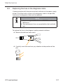
8.3 Replacing the fuse in the diagnosis cable...........................................................127
8.4Cleaning...............................................................................................................................128
8.5Storage.................................................................................................................................128
9Troubleshooting.........................................................................................................128
9.1Resetting.............................................................................................................................128
10Disposal..........................................................................................................................129
10.1Electrical/electronic components...........................................................................129
11EC Declaration of Conformity..............................................................................129
12Homologation..............................................................................................................130
12.1Overview.............................................................................................................................130
12.2Canada.................................................................................................................................130
13Index................................................................................................................................131
CPC hand-held tool
6
General
1
1.1
General
Information on this user manual
This user manual is part of the TPM-02 hand-held tool and provides important instructions on the intended use, safety, startup and operation
of the hand-held tool.
The user manual must be read and utilized by every person who operates this hand-held tool and troubleshoots the hand-held tool.
Store the user manual and give it the any new owner together with the
hand-held tool.
1.2
Liability disclaimer
The manufacturer assumes no liability for damage and operational
faults resulting from:
■■ failure to observe this user manual,
■■ use for other than the intended purpose,
■■ improper repairs,
■■ unauthorized modifications or
■■ use of non-approved spare parts
1.3
Copyright
This user manual is copyrighted.
The user manual may not be duplicated in whole or in part for other
purposes without the express permission of Continental Reifen Deutschland GmbH.
CPC hand-held tool
7
General
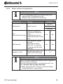
1.4
Abbreviations
The following abbreviations are used in this user manual:
Abbreviation Meaning
1.5
CCU
Central Control Unit
CPC
ContiPressureCheckTM
CSW
CAN switch - switching module (integrated into the
CCU trailer)
DSP
Display
DTC
Diagnostic Trouble Code
HHT
Hand-Held-Tool
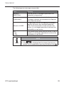
Explanation of symbols
Warnings in this user manual are also indicated by warning symbols.
The following warning symbols are used in this user manual:
Symbol
Meaning
General warning
Warning of electric current
General instructions and useful suggestions on
handling
Note on observing environmental regulations for
disposal
Electric/electronic components with this symbol
may not be disposed of in the normal household
waste.
CPC hand-held tool
8
General
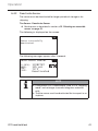
1.6
Warnings
In the current user manual, the following warnings are used:
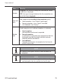
WARNING
A warning of this hazard level indicates a hazardous
situation.
If the hazardous situation is not avoided, it can result in
serious injuries.
►► Follow the instructions in this warning to avoid serious
injuries to persons.
ATTENTION
A warning of this hazard level indicates potential damage to equipment.
If the situation is not avoided, it can result in equipment
damage.
►► Follow the instructions in this warning to avoid the
equipment damage.
NOTE
►► A note draws attention to additional information of
importance for the further work or which simplifies the
work step described.
1.7
Manufacturer's address
Continental Reifen Deutschland GmbH
Büttnerstraße 25
30165 Hannover
Germany
www.contipressurecheck.com
CPC hand-held tool
9
General
1.8
Warranty terms
The statutory warranty terms apply, with the exception of possible contractual agreements.
The current version can be obtained from:
www.contipressurecheck.com
1.9
After-sales service
1.9.1 Eliminating errors
NOTE
►► If the handling instructions in this user manual do
not lead to the elimination of the fault, contact the
after-sales service of the respective country.
All necessary information can be obtained from:
www.contipressurecheck.com
1.9.2 Repairs
In the event of repair of the hand-held tool, a used replacement tool will
be made available. This generally takes place within 24 hours of receiving the defective tool but no later than 72 hours.
Calculation of the costs of replacement takes place according to the
relevant regulations of the warranty (see section „1.8 Warranty terms“
on page 10).
1.9.3 Updates
The current version of this user manual and further information can be
obtained from
www.contipressurecheck.com
CPC hand-held tool
10
Safety
2
2.1
Safety
General safety instructions
Observe the following general safety instructions to ensure safe handling of the hand-held tool:
■■ Check all parts of the hand-held tool for visible damage before use. Do not use a damaged hand-held tool.
■■ Do not allow the hand-held tool to fall down or subject it to
hard knocks.
■■ With the exception of the slot for the SD memory card, do not
open the hand-held tool. There are no maintenance-relevant
parts inside the hand-held tool.
■■ The rechargeable battery of the hand-held tool can not be
replaced.
■■ Only allow the manufacturer to repair the hand-held tool.
Improper repairs or opening the tool will invalidate the guarantee.
■■ Protect the hand-held tool against humidity or penetration of
liquids or objects. If the tool comes into contact with liquids,
disconnect it from the power supply immediately.
CPC hand-held tool
11
Safety
2.2
Electric shock hazard
WARNING
Danger to life from electric current!
Contact with live wires or components can lead to serious
injury or even death!
►► Only use the power adapter supplied otherwise the
hand-held tool could be damaged.
►► Doe not use the hand-held tool if the connecting cable
or the housing or the power adapter is damaged.
►► Never open the housing of the power adapter. Danger
from electric shock if live connections are touched
and/or the electrical and mechanical configuration is
changed.
►► Never immerse the hand-held tool or the mains plug
into water or other liquids.
2.3
Spare parts and accessories
ATTENTION
Damage and malfunctions due to incorrect spare parts
and accessories.
The hand-held tool or vehicle components can be damaged or malfunction if wrong or non-original spare parts
are used.
►► Use original parts only.
►► Only use the original diagnosis cable for transferring
data between the hand-held tool and the CPC system
otherwise data transfer errors can occur.
CPC hand-held tool
12
Safety
2.4
Intended use
The hand-held tool is intended to be used only
■■ for communicating with and setting the tire sensors,
■■ for reading the pressure and temperature values,
■■ for setting up/adjusting the CPC system on the vehicle,
■■ for checking the system performance,
■■ for error diagnostics,
■■ for transferring data between the PC and the hand-held tool
and
■■ updating the software.
Use for any other purpose is not considered as intended use.
WARNING
Hazard from use for other than the intended purpose!
If used for other than its intended purpose, the hand-held
tool can be a source of danger and cause damage to
equipment.
►► Use the hand-held tool only for its intended purpose.
No claims of any kind will be accepted for damage resulting from use for
other than the intended purpose.
In such cases, the risk must be borne solely by the user.
CPC hand-held tool
13
Technical data
3
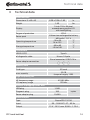
Technical data
Hand-held tool
Dimensions (L x W x H)
Weight
Display
6.29 x 3.54 x 1.49
in.
1.65
lbs
3-inch 128 x 64 pixel
monochrome graphic LCD
with backlighting
Degree of protection
Power pack
Operating temperature
Storage temperature
IP 54
Lithium-ion rechargeable battery
850 mAh / 11.1 V
-10 to 50
°C
14 to 122
°F
-40 to 85
°C
-40 to 185
°F
Connections
USB 2.0 (PC)
of diagnostic cable
Type A
Hirose, 24-pole
Barrel connector, 0.05/0.14 in.
Power adapter connection
Memory card
Card type
max. capacity
SD card
32 GB
(scope of supply 1 GB)
High-frequency part
HF frequency range
433.92 MHz
LF frequency range
125 kHz
Number of plugging cycles, min.
USB plug
Diagnosis plug
Power adapter plug
1,000
100
cycles
10,000
Power adapter
Type
Sinpro SPU 15-106
Input
90 ... 264 VAC / 47 ... 63 Hz
Output
CPC hand-held tool
13 V - 16 V / max. 0.94 A - 1.15 A
14
Description
4
4.1
Description
Description of function
The TPM-02 hand-held tool is a configuration and diagnostics device
with the following functions:
■■ Tire sensor check,
■■ Tire pressure and temperature measuring,
■■ Tire sensor activation/deactivation,
■■ New Installation on the vehicle/trailer,
■■ Checking and changing the existing configuration,
■■ Checking the system performance (test drive),
■■ Reading of error codes (DTCs),
■■ Updating firmware for the display (DSP), CCU and switching
module (CSW),
■■ Logging vehicle and configuration data,
■■ Communication between the PC and the hand-held tool.
CPC hand-held tool
15
Description
4.2
Tool overview
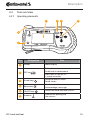
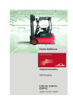
4.2.1 Operating elements
1
2
3
4
6
5
Pos
1
Designation
Screen
Task
Menu display.
Exit a sub-menu.
Scroll back in some menus.
2
ESC key
3
Arrow keys
Navigate within a menu.
Setup values
4
Return key
Confirm selection.
Acknowledge a message.
5
ON/OFF key
Switch the hand-held tool ON/OFF.
6
Antenna
Antenna for quering the
tire sensors.
CPC hand-held tool
Press the ESC key for 3 s.
= cancel an action.
16
Description
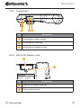
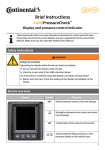
4.2.2 Underside
1
Continental
17340230000
A2C81336600
2
Handheld tool
www.contipressurecheck.com
Tested To Comply with FCC ID: IFKTMP
XXXX
IC ID: XXXX-XXXXXXXX
FCC Standards.
RLVTETP13
RLVTETP13-1125
Other homologation
XXXX
Anatel:: XXXX-XX-XXXX
see owner-manual
CONTAINS LI ION POLYMER BATTERY.
BATTERY BATTERY
MUST BE RECYCLED OR DISPOSED OF PROPERLY.
PROPERLY
Made in Italy
Serial No. T121150XXX
N136
5
Pos
4
3
Designation
1
Slot for SD memory card
2
Type plate
3
Cover for power adapter connection sockets
4
Cover for USB and diagnosis cable connection sockets
5
CPC hand-held tool
Fixing for carrying strap*
*not included in the scope of supply
17
Description
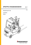
4.2.3 Connections
2 3
1
Pos
Designation
1
Connection for power adapter
2
Connection for USB cable
3
Connection for diagnosis cable
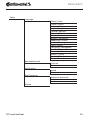
4.2.4 Slot for SD memory card
1
2
Continental
17340230000
A2C81336600
Handheld tool
www.contipressurecheck.com
Tested To Comply with FCC ID: IFKTMP
XXXX
IC ID: XXXX-XXXXXXXX
FCC Standards.
RLVTETP13
RLVTETP13-1125
Other homologation
XXXX
see owner-manual
Anatel:: XXXX-XX-XXXX
CONTAINS LI ION POLYMER BATTERY.
BATTERY BATTERY
MUST BE RECYCLED OR DISPOSED OF PROPERLY.
PROPERLY
Pos
Made in Italy
Serial No. T121150XXX
Designation
1
Cover for SD memory card slot
2
Fixing screw for cover
CPC hand-held tool
N136
18
Description
4.3
Menu structure
Tire sensor
Check sensor
Activate Sensor
Deactivate Sensor
Actions on Tire
Show
Check
Activate
Deactivate
Check all tires
Sniffing Tool
Trigger Tool
Installation
New Installation
Resume installation
Test drive
Modification
Modify Installation
Check Installation
Modify Parameters
Modify Sensor IDs
Activate CPC
Deactivate CPC
Diagnosis
DTC (error code)
Global DTCs
Tire related DTCs
Erase all DTCs
Save DTCs
SW Update
CCU (control unit)
DSP (display)
CSW (switching module integrated into the CCU trailer)
Connection to the PC
CPC hand-held tool
19
Description
Setup
Language
Česky / Czech
Dansk / Danish
Deutsch / German
English / English
Español / Spanish
Français / French
Italiano / Italian
Magyar / Hungarian
Nederlands / Dutch
Norske / Norwegian
Polski / Polish
Português / Portuguese
Româna / Rumanian
Slovenský / Slovak
Soumi / Finnish
Svenskt / Swedish
Türkçe / Turkish
Measurement unit
Pressure
Temperature
Sound setup
Sound
Vibration
Tool Properties
Automatic power-off
Date/time
Use date
Release
CPC hand-held tool
20
Description
4.4
Menu control
Operating the hand-held tool takes place menu-driven via the keys of
the tool. The following lists the possible operating steps:
4.4.1 Calling a menu function
Use the arrow keys
to select the desired menu item.
and call up the menu
Confirm selection with the Return key
item.
If the menu includes submenus, use the arrow keys to select the
desired menu item and confirm selection with the Return key .
Press the ESC key
to return to the previous menu level.
Press the ESC key
for 3 s to cancel an action.
4.4.2 Changing a selection
Use the arrow keys
to select between the settings/options.
Confirm selection with the Return key
.
4.4.3 Scroll symbol
If the space on the screen is not sufficient to display all entries, a scroll
symbol
or
appears on the right-hand side. All entries can be called
with the arrow keys .
CPC hand-held tool
21
Description
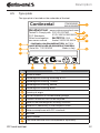
4.5
Type plate
The type plate is located on the underside of the tool.
Continental
17340230000
A2C81336600
Handheld tool
www.contipressurecheck.com
Tested To Comply with FCC ID: IFKTMP
IC ID: XXXX-XXXXXXXX
FCC Standards.
RLVTETP13
RLVTETP13-1125
Other homologation
Anatel: XXXX-XX-XXXX
see owner-manual
14
CONTAINS LI ION POLYMER BATTERY.
BATTERY BATTERY
MUST BE RECYCLED OR DISPOSED OF PROPERLY
PROPERLY.
13
Serial No. T121150XXX
Made in Italy
1
2
3
4
5
6
12
N136
11
Pos
10
9
8
7
Meaning
1
Article number
2
Homologation marking according to FCC
3
Homologation marking, Canada
4
Homologation marking, Mexico
5
Homologation marking, Brazil
6
Country of origin
7
Do not dispose of in the household garbage
8
Contains materials that can be recycled
9
Note on the Homologation marking, Australia
10
Note on CE conformity in the European Union
11
Note on compliance with FCC standards
12
Barcode
13
Serial number
14
The hand-held tool must be disposed of separately.
CPC hand-held tool
22
Commissioning
5
5.1
Commissioning
Checking contents and packaging
As standard, the hand-held tool is supplied with the following components:
■■ Hand-held tool (incl. 1 GB SD memory card)
■■ Diagnosis cable
■■ USB cable
■■ Power adapter
■■ 4 power plugs EU (European Union), UL (USA),
UK (England), AU (Australia)
■■ CD-ROM
■■ Brief instructions
■■ Homologation certificate
■■ 2 replacement fuses for the diagnosis cable
■■ Transport case
NOTE
►► Check for visible signs of damage or missing items on
delivery. Report an incomplete or damaged delivery to
your supplier/retailer immediately.
CPC hand-held tool
23
Commissioning
5.2
Charging the hand-held tool
Switch on the hand-held tool.
Remove the cover for the connection socket of the power adapter.
Connect the connecting cable of the power adapter and plug the
power adapter into a mains socket.
After approx. 10 seconds, the tool switches itself off automatically
and a charging symbol
is displayed on the screen.
NOTE
or charging symbol
is
►► If an adapter
not displayed during charging, the tool is not being
charged sufficiently.
NOTE
►► Only use the power adapter supplied.
►► The charging process takes approx. 7 hours.
►► For accreditation reasons, the hand-held tool may not
be operated when the mains adapter is connected.
5.2.1 Charging state display
■■ If the hand-held tool is running on battery power, the
charging state is displayed by a battery symbol
in the
top right corner of the screen. The level indicated on the
battery symbol corresponds to the charging state of the
rechargeable batteries
.
■■ If the hand-held tool is connected via the power adapter, a
plug symbol appears in the upper right corner of the screen
.
CPC hand-held tool
24
Commissioning
5.3
Changing the memory card
The files required for updating the firmware of the display, CCU and the
switching module (CSW) are stored on the SD memory card built into
the hand-held tool.
The data for the system languages is also stored on the SD memory card
serves as storage location for the log files created by the hand-held tool.
NOTE
►► An SD memory card is supplied with the hand-held tool
by default.
►► For communicating with the SD memory card, the
hand-held tool is connected to the PC/Laptop via a
USB cable, see section „8.2 Connection to the PC“ on
page 125. The SD memory card remains in the handheld tool.
►► Do not erase or modify the data on the memory card
as this leads to malfunctions or even total failure of the
hand-held tool.
►► The log files are an exception!
These can be erased without influencing the system.
CPC hand-held tool
25
Commissioning
1
2
Continental
17340230000
A2C81336600
Handheld tool
www.contipressurecheck.com
Tested To Comply with FCC ID: IFKTMP
XXXX
IC ID: XXXX-XXXXXXXX
FCC Standards.
RLVTETP13
RLVTETP13-1125
Other homologation
XXXX
Anatel:: XXXX-XX-XXXX
see owner-manual
CONTAINS LI ION POLYMER BATTERY.
BATTERY BATTERY
MUST BE RECYCLED OR DISPOSED OF PROPERLY.
PROPERLY
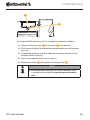
To replace the SD memory card if it is defective, proceed as follows:
Serial No. T121150XXX
Made in Italy
LoosenN136
the fixing screw 2 of the cover 1 and remove it.
Push the card lightly to release the locking mechanism of the memory card.
Change the memory card. Pay attention to proper location of the
contacts when inserting.
Push in the memory card until it snaps in.
Replace the cover 1 and tighten the fixing screw 2 .
NOTE
►► Information on setting up the new SD memory card
is available on the website www.contipressurecheck.
com.
CPC hand-held tool
26
Commissioning
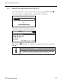
5.4
Switch the hand-held tool ON/OFF
The hand-held tool is switched on or off by pressing the ON/OFF key
.
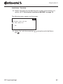
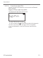
The start screen is displayed for 3 seconds after switching on.
Conti PressureCheck
by
CONTINENTAL
The following main menu then appears:
CPC
Tire Sensor
Installation
Modification
Diagnosis
Setup
dd-mmm-yyyy
Pressing the
tool off.
hh:mm
key again for approx. 3 seconds switches the hand-held
NOTE
►► The date and time display can be activated in the main
menu under Setup - Tool Properties - Use Date.
CPC hand-held tool
27
Commissioning
5.5
Setting up the hand-held tool
Fundamental tool settings such as language, units etc. are determined
in the "Setup" menu.
Menu item
Language
Meas. unit
Sound setup
Meaning
Selection
Danish. German, English,
Finnish, French, Italian,
Operating language
Dutch, Norwegian, Polish,
of the screen
Portuguese, Rumanian,
Swedish, Slovak, Spanish,
Czech, Turkish, Hungarian
Pressure
bar/psi
Unit for pressure
and temperature
Temperature °C/°F
Signal output
Sound
On/off
as sound and/or
Vibration
On/off
vibration
Time, after which
the hand-held tool
is switched off
automatically.
Tool Properties
Release
CPC hand-held tool
Automatic
switch-off
Off
5min
10min
15min
System date
and time
Data and time setting. Date
format can be selected.
Use date and time (yes / no).
Use date
——Display in the main menu
Information on the
firmware
——Use with log files
Display of the FW version
and the serial number
28
Commissioning
Select the desired menu item with the arrow keys
and confirm with the Return key
.
Navigate between the menu items with the arrow keys and
.
change the values / settings with the arrow keys
. The selection is stored
Confirm selection with the Return key
and you are returned to the next highest level of the menu.
The submenu is exited by pressing the ESC key
"Setup" menu without making any changes.
and to the
NOTE
►► The menu begins with the main setting in English. Select the desired language by following the menu path:
"SETUP/LANGUAGE".
►► If no SD memory card is inserted in the hand-held tool
or it is defective, only "ENGLISH" is available.
CPC hand-held tool
29
Operation
6
6.1
Operation
General instruction
For trouble-free operation, pay attention to the following instructions:
■■ Always operate the hand-held tool with fully-charged batteries so that full transmission power is ensured.
■■ Keep the cover of the hand-held tool closed so that not dirt
particles or fluids can penetrate the hand-held tool.
6.2
Handling the hand-held tool
In order to communicate with the tire sensors, the hand-held tool is
equipped with an antenna. The following describes the procedure for
communication that is used in all menus.
NOTE
►► Always hold the antenna in the direction of the sensor
in order to ensure the best possible communication.
►► If sound and/or vibration was switched during setup,
a corresponding signal is emitted after successful
reading.
►► The read operation takes place via 3 steps with
increasing transmission power. If communication beyond that is still not possible, the process is aborted.
CPC hand-held tool
30
Operation
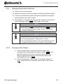
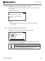
6.2.1 Reading an accessible sensor
In the event that the sensor is easily accessible, proceed as follows for
reading:
Hold the hand-held tool with antenna
sensor as illustrated.
directly in front of the
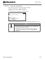
6.2.1.1 Problem when reading - communication failed
If communication with the sensor is not possible, the following message
appears::
Communication
failed.
Refer to manual.
Remedy:
1. Check the charging state of the hand-held tool and charge if necessary.
2. Repeat the procedure with another tire sensor.
►►If communication is possible, the 1st tire sensor is defective.
►►If communication is still not possible, contact after-sales service.
CPC hand-held tool
31
Operation
6.2.1.2 Problem when reading - other sensor in range
If a further sensor is within radio range, the sensor to be checked cannot
be safely read.
The following appears:
OTHER SENSORS IN RANGE!
MOVE THE SENSOR AND CHECK
AGAIN.
Remedy:
Put the sensor out of range of the other sensors or sources of
interference.
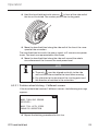
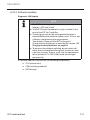
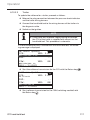
6.2.2 Fetching a sensor fitted in the tire
When fetching the tire sensors, the following is displayed:
PWR: XX%
1/3
In the animation, the marker point moves along the side wall in a specified direction and at a specified speed.
NOTE
►► The percentage indicates the current pending transmission power (PWR) of the query signal.
CPC hand-held tool
32
Operation
Hold the hand-held tool with antenna
in front of the side wall of
the tire as illustrated. The marker point is the starting point.
Move the hand-held tool along the side wall of the tire at the same
speed of the animation.
The hand-held tool transmits the query signals at 3 transmission power
levels. The levels are represented on the screen.
Move the hand-held tool along the side wall around the whole
circumference of the tire once for each power level.
NOTE
must be aligned vertically to the side
►► The mark
wall and the antenna below the tread when moving.
►► Pay attention to the location of the starting point and
the direction of rotation in the animation.
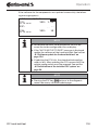
6.2.2.1 Problem when fetching - 2 different sensors
If the hand-held tool reaches 2 different sensors, the following message
appears:
MORE THAN ONE SENSOR
RECEIVED!
MOVE TOOL WITH SPEED
SHOWN IN ANIMATION.
Repeat the fetching procedure for this tire.
CPC hand-held tool
33
Operation
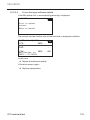
6.3
Screen displays
Vehicle depiction:
H CO 123
Shows the vehicle configuration from the top.
Axle depiction:
Choose config.
←
→
Shows the axle/tire configuration at a part of the vehicle.
CPC hand-held tool
34
Operation
Tire depiction:
To visualize the tire sensor data, the color and the content of the tire
symbol changes.
Illustration
Meaning
Existing tires.
Fetched sensor with data:
1. Tire pressure.
X.X
or
2. number of telegrams or RSSI (see „6.7 Test drive“ on
page 74).
Faulty sensor.
Show details on faults:
!
■■
Select tire with the corresponding arrow keys.
(tire marked with "[ ]").
■■
Confirm selection with the
Return key
.
(for possible faults, see chart in section „6.4.1 Check sensor“ on page 38)
X.X
Fetched, deactivated sensor (shipping mode)
Sensor not found.
Tire are shown in this way when the focus is on the axle
A tire symbol marked with "[ ]" is focused in the menu.
CPC hand-held tool
35
Operation
To visualize additional information in the case of error codes (DTC), the
tire symbol could be displayed inverted or flashing.
Illustration
X.X
Meaning
The following applies when indicating errors:
Symbol is flashing:
active DTCs pending.
Symbol not flashing:
passive DTCs pending.
(see „6.10.1.2 Read tire-releated error codes (DTCs)“ on
page 107)
CPC hand-held tool
36
Operation
6.4
Tire Sensor menu
Sensors can be checked, activated and deactivated in "Tire sensor"
menu. Tire-related sensors can be queried for a specific vehicle under
the submenu items "Actions on tire" and "Check all tires". Furthermore,
the surroundings of the hand-held tool can be checked for existing sensors and what power transmission level of the query signal is required
for them to respond.
CPC hand-held tool
37
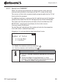
Operation
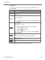
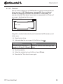
6.4.1 Check sensor
Tire sensor - Check sensor
Read sensor as described in section „6.2.1 Reading an accessible
sensor“ on page 31.
The following is displayed on the screen:
Check Sensor
ID (HEX):
PRESS:
TEMP:
STATE:
1C28F787
125 psi
73°F
Activated
Field
Meaning
ID (hex)
Identification number of the sensor.
PRESSURE
Tire pressure (in a dismantled state, 0 bar/0 psi).
TEMP
Ambient temperature of the sensor.
activated
= park mode
Sensor is at idle. A telegram is transmitted every 2 minutes.
deactivated
= shipping mode
Sensor only transmits telegrams when
specifically queried.
START mode
Beginning at a speed of approx. 30
km/h (18 mph), a telegram is transmitted 40-times every 16 seconds.
DRIVE mode follows.
DRIVE mode
Sensor is moving. A telegram is transmitted every 2 minutes.
STATUS
CPC hand-held tool
38
Operation
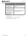
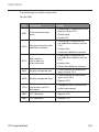
The following error messages are possible:
Error
Meaning
Sensor is
DEFECTIVE
The tire sensor is no longer operational. Replace with a new sensor.
LOW battery
The capacity of the battery in the tire sensor is
no longer sufficient for continued use. Replace
with a new tire sensor.
Sensor is LOOSE
It is possible that the tire module has become
loose in the tire or was mounted head over
heels. If this error occurs in the case of a tire
sensor, it is no longer operational and must be
replaced by a new sensor.
ACC
>5g
< -5 g
If this error occurs when the tire sensor is not in
motion, it is no longer operational and must be
replaced by a new sensor.
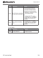
NOTE
►► If the
is displayed on the screen, the test procedure can be repeated by pressing the Return key
.
CPC hand-held tool
39
Operation
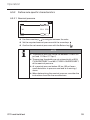
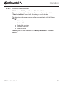
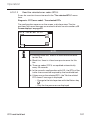
6.4.2 Activate Sensor
By default, the sensor is deactivated and does not transmit any telegrams automatically. In order to be able to operate the sensor at the
vehicle, it must be activated.
Tire Sensor - Activate Sensor
Read sensor as described in section „6.2.1 Reading an accessible
sensor“ on page 31.
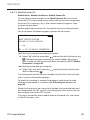
The following is displayed on the screen:
Sensor successfully
activated.
The following messages appears after 3 seconds:
Activate Sensor
ID (HEX):
PRESS:
TEMP:
STATE:
CPC hand-held tool
1C28F787
125 psi
73°F
Activated
40
Operation
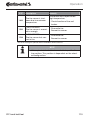
6.4.3 Deactivate Sensor
The sensor must be deactivated for longer periods of storage or for
shipping.
Tire Sensor - Deactivate Sensor
Read sensor as described in section „6.2.1 Reading an accessible
sensor“ on page 31.
The following is displayed on the screen:
Sensor successfully
deactivated.
The following messages appears after 3 seconds:
Deactivate Sensor
ID (HEX):
PRESS:
TEMP:
STATE:
1C28F787
125 psi
73°F
Deactivated
NOTE
►► If the sensor is in a "deactivated" state, it is in "shipping
mode" and no longer transmits telegrams automatically.
►► The tire sensor must be deactivated for transport in an
airplane.
CPC hand-held tool
41
Operation
6.4.4 Actions on tire
For tire-related query/operation of sensors installed in a vehicle, the
sensors with their associated tires must be fetched first.
Tire sensor - Actions on tire
Query of the tires takes place in 3 steps:
1. Selection of the axle configuration.
2. Fetching the tire sensors
3. Specific communication with the tire sensors.
6.4.4.1 Select axle configuration
The following is displayed on the screen:
Choose config.
←
→
Move between the axle configurations with the arrow keys
Confirm selection with the Return key
CPC hand-held tool
.
.
42
Operation
6.4.4.2 Fetching tire sensors
Now each individual sensor can be fetched. The current tire to be
fetched is marked on the screen by "[ ]":
The following is displayed on the screen:
Read sensors:
Read the sensor with the hand-held tool as described in the section
„6.2.2 Fetching a sensor fitted in the tire“ on page 32.
When the sensor is found in the marked tire, the tire pressure at the time
of fetching tire is displayed in the tire symbol and the next tire to be
fetched is displayed.
Fetch all tires as specified on the screen. The following message appears
for the last tire to be fetched:
Read sensors:
119
122
When the fetching procedure including the last tire is completed, the
individual sensors can be addressed specifically.
NOTE
►► Remedy possible errors during fetching of the tire
sensors as described in the sections 6.5.7.1, 6.5.7.2,
6.5.7.3 and 6.5.7.4.
►► If a sensor is not acquired, fetching will be aborted.
Fetching will continued for the next tire.
CPC hand-held tool
43
Operation
6.4.4.3 Communicating with the sensors
For specific communication with the tire sensors.:
to navigate between the tires.
Use the arrow keys
to navigate between the 4 menu items.
Use the arrow keys
Execute the selected action by pressing the Return key
.
The following is displayed on the screen:
Actions on Tire
↑ Show
Check
←
Activate
↓ Deactiv.
119
119
→
122
Menu item
Meaning
SHOW
Shows the previously read sensor data for 15
seconds.
Data output as in section „Check sensor“ on
page 38.
CHECK
Query the tire sensor again and to show the
current sensor data for 15 seconds.
Data output as in section „6.4.1 Check sensor“
on page 38
ACTIVATE
Activates the selected sensor. Corresponds to
the function in section „6.4.2 Activate Sensor“
on page 40.
DEACTIVATE
Deactivates the selected sensor. Corresponds
to the function in section „6.4.3 Deactivate
Sensor“ on page 41.
CPC hand-held tool
44
Operation
To exit the "Actions on tire" menu, press the ESC key
seconds.
for 3
The following screen appears.
Exit from
Actions on Tire?
← → No
Select "Yes" with the arrow keys
key
.
CPC hand-held tool
and confirm with the Return
45
Operation
6.4.5 Check all tires
This menu item is used for querying the sensor data in the case of vehicles without their own CCU and display. The entire vehicle configuration
must be fetched.
Tire sensor - Check all tires
Querying the tires takes place in 5 steps:
1. Name of the vehicle
2. Selection of the vehicle configuration
3. Read/fetch the tire sensors
4. Create a log file
5. If required: display details of the sensor data
CPC hand-held tool
46
Operation
6.4.5.1 Enter vehicle name
The vehicle name serves to identify the vehicle and the associated configuration. The vehicle name is stored in the log file.
See also „7.4 Log files“ on page 122.
VEHICLE NAME
1
Q
Z
2
A
W
X
3
S
E
C
4
D
R
V
5
F
T
B
6
G
Y
N
7
H
Use the arrow keys
U
M
8
J
I
9
K
O
0
P
L
OK
to select the numbers and letters.
Confirm selection with the Return key
.
Select "OK" and confirm with the Return key
name is complete.
when the vehicle
NOTE
►► 19 characters - max. length of the vehicle name.
►► If an individual name is not entered, "NO VEHICLE
NAME" is used as vehicle name.
►► As an example for this description, "H CO 123" was
used as the vehicle name.
CPC hand-held tool
47
Operation
6.4.5.2 Select vehicle configuration
Characteristic
Meaning
Selection
Vehicle type
Type of vehicle
Number of axles
The selection options depend on the vehicle type.
Truck/Bus:
Trailer
1-6
When selection is complete, the birds-eye-view of a possible vehicle
appears:
H CO 123
← → to scroll
Use the arrow keys
to move between the configurations.
Confirm selection with the Return key
CPC hand-held tool
.
48
Operation
6.4.5.3 Read/fetch tire sensors
Now each individual sensor can be read/fetched. The current tire to be
fetched is marked on the screen by "[ ]":
H CO 123
↵ to proceed
Take the hand-held tool and go to the marked tire on the vehicle.
Start the fetching process by pressing the Return key
.
An animation of the fetching process appears on the screen:
PWR: XX%
1/3
Read the sensor with the hand-held tool as described in the section
„6.2.2 Fetching a sensor fitted in the tire“ on page 32.
NOTE
►► Pay attention to the starting point and the direction of
rotation in the animation.
Fetched tires are illustrated as in section „6.3 Screen displays“ on
page 34.
CPC hand-held tool
49
Operation
NOTE
►► Remedy possible errors during fetching of the tire
sensors as described in the sections 6.5.7.1, 6.5.7.2,
6.5.7.3 and 6.5.7.4.
►► If a sensor is not acquired, fetching will be aborted.
Fetching will continued for the next tire.
After completion of reading/fetching, a log file is created automatically
and stored to the SD memory card. See also section „7.4 Log files“ on
page 122.
The following is displayed on the screen:
Report file stored.
Vehicle Name_ _ _ _
_V_YYYYMMDD_hhmmss
↵ TO PROCEED
Exit display of the log file with the Return key
.
The overall view of the vehicle appears on the screen.
CPC hand-held tool
50
Operation
6.4.5.4 Display the tire sensor data
Now any tire senor can be selected.
H CO 123
129
122
122
125
125
← → ↑↓ ↵
129
Select the desired tire sensor with the arrow keys
.
Confirm selection of the tire sensor with the Return key
.
The data of the selected tire sensor is displayed. See section „6.4.1
Check sensor“ on page 38.
To return to the overall view of the vehicle:
Press the Return button
or the ESC key
.
Returning to the overall view takes place automatically after
15 seconds.
To exit the menu item:
Press the ESC key
for 3 seconds.
When prompted to exit the menu item, use the arrow keys
press the Return key
and confirm with "Yes".
CPC hand-held tool
and
51
Operation
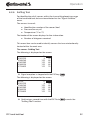
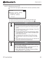
6.4.6 Sniffing Tool
For identification of all sensors within the transmitting/receiving range
of the hand-held tool, data can be collected via the "Signal Collector"
menu.
The sensors transmit:
■■ Identification number of the sensor (hex)
■■ Pressure (bar or psi)
■■ Temperature (°C or °F)
The header of the screen displays further information:
■■ Number of telegrams received
This menu item can be used to identify sensors that are unintentionally
located within the work area.
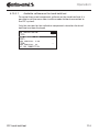
Tire sensor - Sniffing Tool
The following is displayed on the screen:
1C451F3D
1C989F4D
1C46258E
1C498156
1C75483E
5
0
125
125
125
122
70
68
68
66
70
Signal reception is stopped with the ESC key
.
The following is displayed on the screen:
STOP
1C451F3D
1C989F4D
1C46258E
1C498156
1C75483E
5
0
125
125
125
122
70
68
68
66
70
Confirming a second time with the ESC-Taste
"Sniffing Tool" function .
CPC hand-held tool
cancels the
52
Operation
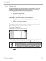
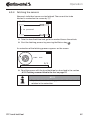
6.4.7 Trigger Tool
A signal with defined transmission power can be emitted to query the
sensors surrounding the hand-held tool. The sensors in the radius of
action of the signal responds with the following data:
■■ Identification number of the sensor (hex)
■■ Status of the sensor (hex)
■■ Specification of the duration between two response telegrams received (in ms).
The header of the screen displays further information:
■■ Transmission power of the querying signal as a percentage (%)
■■ Number of telegrams received
The trigger analysis is able to recognize the proportional transmission
power required in order for the sensor to respond.
Tire sensor - Trigger Tool
The following is displayed on the screen:
Power
1C451F3D
1C989F4D
1C46258E
1C498156
1C75483E
1C468756
1C125F2E
4%
Dh
9h
Dh
Dh
9h
Dh
Dh
15
40
1690
720
80
140
1230
20
The proportional transmission power of the querying signal can be
increase or decreased with the arrow keys .
NOTE
►► When starting the function, the proportional transmission power is 0% and must be increased as described.
Querying is stopped and the function canceled with the ESC
.
key
CPC hand-held tool
53
Operation
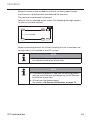
6.5
Initialization of the installed CPC system
NOTE
►► Before initializing the system, make sure that all tire
sensors are activated.
Initialization of the system takes place in 6 steps:
1. Name of the vehicle
2. Selection of the vehicle configuration
3. Definition of axle-specific characteristics
4. Fetching the tire sensors
5. Transfer of the configuration to the CPC system
6. Create a log file
NOTE
►► The installation process can be canceled at any time
by pressing the ESC key
for 3 seconds.
►► It is possible to resume the installation process from
the point where it was aborted via the "Resume installation" menu item.
See section „6.6 Resume initialization“ on page 73.
Installation - New Installation
NOTE
►► By selecting the "Installation" item in the main menu,
the charging state of the battery is checked. If this is
not sufficient, the following message appears:
"Low battery! Power on the HHT to charge it.“
Charge the hand-held tool as described in section „5.2
Charging the hand-held tool“ on page 24.
CPC hand-held tool
54
Operation
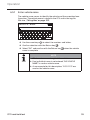
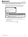
6.5.1 Enter vehicle name
The vehicle name serves to identify the vehicle and the associated configuration. The vehicle name is stored in the CCU and in the log file.
See also „7.4 Log files“ on page 122.
VEHICLE NAME
1
Q
Z
2
A
W
X
3
S
E
C
4
D
R
V
5
F
T
B
6
G
Y
N
7
H
Use the arrow keys
U
M
8
J
I
9
K
O
0
P
L
OK
to select the numbers and letters.
Confirm selection with the Return key
.
Select "OK" and confirm with the Return key
name is complete.
when the vehicle
NOTE
►► 19 characters - max. length of the vehicle name.
►► If an individual name is not entered, "NO VEHICLE
NAME" is used as vehicle name.
►► As an example for this description, "H CO 123" was
used as the vehicle name.
CPC hand-held tool
55
Operation
6.5.2 Select vehicle configuration
NOTE
►► A list of recommended vehicle configurations and
types for the CPC equipment can be
viewed at www.contipressurecheck.com.
Characteristic
Meaning
Selection
Truck/Bus:
Vehicle type
Type of vehicle
Trailer
Married
Automatic recognition
of the newly-connected
ATL
trailer.
(AutoTrailerLearning) (selection only with selected vehicle type "Truck/
Bus")
Add. Receiver
Is an additional receiver
installed.
(Automatic function
when "ATL" is activated
or vehicle type "Married"
selected.)
Number of axles
The selection options depend on the vehicle type.
Yes
No
Yes
No
1-6
NOTE
The CPC system automatically detects when a single tire
with tire sensor is replaced.
Also see: ContiPressureCheck -Installation manual- section "Automatic Wheel Change Detection".
►► When selecting the ATL function, "Automatic Wheel
Change Detection" is deactivated!
CPC hand-held tool
56
Operation
When selection is complete, the birds-eye-view of a possible vehicle
appears:
H CO 123
← → to scroll
Use the arrow keys
tions.
to move between the vehicle configura-
Confirm selection with the Return key
CPC hand-held tool
.
57
Operation
6.5.2.1 Special case "MARRIED"
Select this vehicle type when the tire sensors of the trailer are to be
received and indicated in the display of the CPC system of the truck.
The sensors of the trailer are permanently programmed into the CCU of
the truck for this purpose.
An additional receiver is necessary for this vehicle type and is therefore
automatically linked into the CPC configuration by the hand-held tool.
The trailer must be permanently married to the truck otherwise "NO
RECEPTION” is displayed in the display for the trailer sensors
(see user manual for display)
For the "Married" vehicle type, the number of axles for the respective
truck and trailer is selected separately.
Altogether, it is not possible to select more than 6 axles.
H CO 123
Number of Axles
← →
3 Truck/Bus
2 Trailer
Modify the selection with the arrow keys
Confirm selection with the Return key
.
.
NOTE
►► The "ATL" function cannot be selected with this configuration.
►► "Automatic Wheel Change Detection" is active.
Also see: ContiPressureCheck Installation manual section "Automatic Wheel Change Detection".
CPC hand-held tool
58
Operation
6.5.3 Define axle-specific characteristics
6.5.3.1 Nominal pressure
H CO 123
119 116
116
Use the arrow keys
to navigate between the axles.
Set the required nominal pressure with the arrow keys .
Confirm the set nominal pressures with the Return key
.
NOTE
►► The nominal pressure can be set between 1.8 bar (26
psi) and 11.9 bar (173 psi ).
►► The warning thresholds are set automatically at 90%
("LOW PRESSURE“) and 80% ("VERY LOW PRESSURE“)
of the nominal pressure.
►► At a nominal pressure below 4.5 bar (65 psi) even
small deviations in pressure can lead to a warning /
alarm.
►► When determining the nominal pressure, consider the
instructions from the tire manufacturer.
CPC hand-held tool
59
Operation
6.5.3.2 Nominal pressure at ATL
This menu item only appears when the ATL function is previously selected.
H CO 123
Nominal press.(ATL)
- valid for all
trailer axles.
← →
116 psi
Set the required nominal pressure with the arrow keys
Confirm the set nominal pressure with the Return key
.
.
NOTE
►► Only one nominal pressure can be defined for all axles!
►► The nominal pressure applies to all newly-connected
trailers!
►► The nominal pressure can be set between 1.8 bar (26
psi) and 11.9 bar (173 psi ).
►► The warning thresholds are set automatically at 90%
("LOW PRESSURE“) and 80% ("VERY LOW PRESSURE“)
of the nominal pressure.
►► At a nominal pressure below 4.5 bar (65 psi) even
small deviations in pressure can lead to a warning /
alarm.
►► When determining the nominal pressure, consider the
instructions from the tire manufacturer.
NOTE
The CPC system automatically detects when a single tire
with tire sensor is replaced.
Also see: ContiPressureCheck -Installation manual- section "Automatic Wheel Change Detection".
►► When selecting the ATL function, "Automatic Wheel
Change Detection" is deactivated!
CPC hand-held tool
60
Operation
6.5.3.3 Lift axle
Depending on the vehicle type, an axle can also be defined as a lift axle.
H CO 123
-
✓
Use the arrow keys
-
to navigate between the axles.
Change the status with the arrow keys :
„✓“ = lift axle
„-“ = no lift axle
Confirm selection with the Return key
.
General conditions:
■■ If the selected configuration only has 2 axles (a truck or drawbar trailer) or only 1 axle (semitrailer), the page for determining the lift axle is not displayed.
■■ In the case of trucks or drawbar trailers, at least 2 ales may
not be lift axles and in the case of the semitrailer only 1 axle.
■■ In the case of a truck or drawbar trailer, the 1st axle can not
be set as lift axle.
■■ Altogether for each installation, a maximum of 2 axles from
possible 6 can be set as lift axle (if the vehicle type is selected
as "MARRIED", this is considered as one installation).
NOTE
►► Lift axle setup must be made carefully.
►► If the lift axles are wrongly determined, correct function of the CPC system cannot be ensured.
CPC hand-held tool
61
Operation
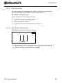
6.5.4 Fetching tire sensors
Now each individual sensor can be fetched. The current tire to be
fetched is marked on the screen by "[ ]":
H CO 123
↵ to proceed
Take the hand-held tool and go to the marked tire on the vehicle.
Start the fetching process by pressing the Return key
.
An animation of the fetching process appears on the screen:
PWR: XX%
1/3
Read the sensor with the hand-held tool as described in the section
„6.2.2 Fetching a sensor fitted in the tire“ on page 32.
NOTE
►► Pay attention to the starting point and the direction of
rotation in the animation.
CPC hand-held tool
62
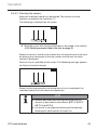
Operation
When the sensor in the marked tire is found, the tire symbol changes
and the entry is displayed with the detected tire pressure.
The next tire to be fetched is displayed.
Fetch all tires as specified on the screen. The following message appears
for the last tire to be fetched:
H CO 123
122
129
↵ to proceed
129
125
125
When the fetching process for all tires including the last is complete, the
configuration is transmitted to the CPC system.
NOTE
►► To fetch the tire sensor of the inner twin tires, the tool
can remain on the outer of twin tires.
NOTE
►► If the fetching process is aborted, the fetching process
must be restarted from the beginning via the "Resume
installation" menu item.
►► All tires must be fetched again.
See section „6.6 Resume initialization“ on page 73.
CPC hand-held tool
63
Operation
6.5.5 Transfer of the configuration to the CPC system
In order for the data to be transferred to the CPC system, the hand-held
tool must be connected to the CPC system via the diagnosis cable.
The following message appears on the screen of the hand-held tool:
H CO 123
CONFIGURATION COMPLETED.
CONNECT TOOL WITH DISPLAY.
IGNITION ON.
START UPLOAD.
NOTE
►► To ensure safe transfer of the configuration, do not
switch off the hand-held tool during data transfer or
interrupt data transfer.
To transfer the configuration for a truck/bus, proceed as follows:
Connect the hand-held tool to the plug socket of the display via the
diagnosis cable.
Switch on the ignition.
Start transmission with the Return key
CPC hand-held tool
.
64
Operation
To transfer the configuration for a trailer, proceed as follows:
Release the plug connection between the pressure check indicator
and the trailer wiring harness.
Connect the hand-held tool to the wiring harness via the diagnosis
cable.
Switch on the ignition.
Start transmission with the Return key
.
NOTE
►► If the trailer has no power supply during installation,
the CCU of the trailer is supplied with current via the
hand-held tool. This procedure is automatic.
The following message appears during transfer:
H CO 123
Upload in progress.
Please wait...
CPC hand-held tool
65
Operation
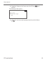
6.5.6 Log file
To complete transmission of the configuration data to the CPC system, a
log file is created automatically and stored on the SD memory card. See
also section „7.4 Log files“ on page 122.
The following is displayed on the screen:
Report file stored.
Vehicle Name_ _ _ _
_I_YYYYMMDD_hhmmss
↵ TO PROCEED
After successful data transmission, the following appears:
H CO 123
Upload completed!
NOTE
►► The previously-set configuration is always stored on
the hand-held tool. The advantage of this is that initialization of several vehicles with the same configuration
is easier.
NOTE
►► During every software update or every parameter
modification on the CCU (“New Installation“, “Modify
Parameters“, “Modify Sensor IDs“) all saved DTCs (error
codes) are erased!
See also section „6.10 Diagnosis“ on page 98
CPC hand-held tool
66
Operation
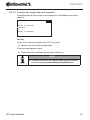
6.5.7 Possible problems
6.5.7.1 Sensor not found after 2 attempts
Sensor was not found after the first fetching attempt. The following
message appears on the screen:
H CO 123
NO SENSOR FOUND!
MOVE THE TOOL WITH SPEED
SHOWN IN THE ANIMATION.
Repeat the fetching process of the tire.
If the hand-held tool does not find the sensor after the second attempt,
the fetching process is stopped and the following message appears:
H CO 123
NO SENSOR FOUND!
TEACH-IN STOPPED.
CHECK IF SENSOR IS PRESENT
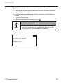
IN TIRE.
Acknowledge the message with the Return key
CPC hand-held tool
.
67
Operation
Remedy:
1. Check the charging state of the hand-held tool.
►►The charging state must be at least 40%.
►►If the charging state is sufficient, there is no sensor in the tire,
the sensor is not operational or is defective.
2. Dismantle the tire for exact checking.
3. In the case of some tires and special vehicles, it is possible that the
strength of the querying signal is not sufficient. Contact after-sales
service for adjustment.
4. To initialize the CPC system, proceed as described in the section
„6.6 Resume initialization“ on page 73.
CPC hand-held tool
68
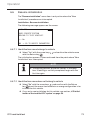
Operation
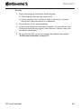
6.5.7.2 2 Different sensors found simultaneously
The following message appears on the screen:
H CO 123
MORE THAN ONE SENSOR
RECEIVED!
MOVE TOOL WITH SPEED
SHOWN IN ANIMATION.
Repeat the fetching process of the tire.
If the hand-held tool finds 2 sensor again, the fetching process is
stopped and the following message appears:
H CO 123
MORE THAN ONE SENSOR
RECEIVED!
TEACH-IN STOPPED.
REFER TO MANUAL.
Acknowledge the message with the Return key
.
Remedy:
Check wether additional sensors are located within a range of 2 m of the
tires.
►►If yes, remove the sensors from the communication range and
repeat the fetching procedure.
►►If no, move the vehicle approx. 1 m forwards or backwards and
repeat the fetching procedure.
CPC hand-held tool
69
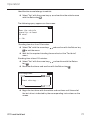
Operation
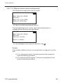
6.5.7.3 Sensors not activated
The following message appears on the screen:
H CO 123
SENSOR NOT ACTIVATED!
MOVE THE TOOL WITH SPEED
SHOWN IN THE ANIMATION.
Acknowledge the message with the Return key
.
PWR: 180%
1/3
Repeat the fetching process of the tire.
NOTE
►► The sensor is automatically reset to park mode and
fetched.
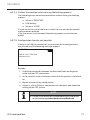
H CO 123
128
Fetch the next sensor.
CPC hand-held tool
70
Operation
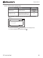
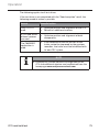
6.5.7.4 Further termination criteria during the fetching process
The following errors constitute termination criteria during the fetching
process:
■■ Sensor is DEFECTIVE
■■ LOW battery
■■ Sensor is LOOSE
If a tire sensor has one of the errors stated, the tire must be dismantled
and the sensor replaced.
If the tire sensor is not renewed, the fetching process cannot be completed.
6.5.7.5 Configuration transfer not possible
If there is no CAN bus connection, transmission of the configuration is
not possible and the following message appears.
H CO 123
Check the CAN bus
connection.
Remedy:
1. Check the connection between the hand-held tool, the diagnosis
cable and the CPC components.
2. In the case of a truck installation, check that the ignition is switched
on.
3. Repeat transfer of the configuration.
4. If there is still no CAN bus connection, exit the menu and check the
cabling of the CPC system.
NOTE
►► Further instructions on troubleshooting can be found
on the homepage www.contipressurecheck.com.
CPC hand-held tool
71
Operation
6.5.7.6 Transferred configuration not accepted
If configuration of the system is not successful, the following message
appears:
H CO 123
Error in upload
process!
Refer to manual.
Remedy:
In this case, communication to the CCU has failed.
Repeat transfer of the configuration.
If the message appears again:
Check the entire cabling and replace if necessary.
NOTE
►► Further instructions on troubleshooting can be found
on the homepage www.contipressurecheck.com.
CPC hand-held tool
72
Operation
6.6
Resume initialization
The "Resume installation" menu item is only active when the "New
Installation" procedure was interrupted.
Installation - Resume installation
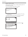
The following message appears on the screen:
H CO 123
DOES IDENTIFICATION
BELONG TO THIS VEHICLE?
← → No
NO -> GO TO MODIFY PARAMETERS
6.6.7.1 Identification name belongs to vehicle
Select "Yes" with the arrow keys
with the Return key
.
and confirm the vehicle name
The initialization process is then continued from the point where "New
Installation" was interrupted.
NOTE
►► The fetching process of the tire sensors is an exception. If fetching is not fully completed, begin with the
first tire again.
6.6.7.2 Identification name does not belong to vehicle
Select "No" with the arrow keys
and confirm with the Return
key
to exit the menu item otherwise a wrong configuration is be
installed for this vehicle.
Carry out a new installation for this vehicle, see section „6.5 Initialization of the installed CPC system“ on page 54.
CPC hand-held tool
73
Operation
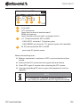
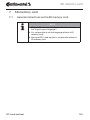
6.7
Test drive
The "Test drive" menu item is used for checking the reception quality of
the CPC system built into the vehicle.
For this purpose, the following data is acquired:
1. The number of telegrams from the individual sensors received.
2. The signal strength of the individual sensors acquired by the
receiver.
The data received is evaluated by the hand-held tool and the result
output in in 3 steps:
■■ Good reception
■■ Enough reception
■■ Just sufficient
NOTE
►► In order to be able to check the reception quality of all
installed tire sensors, all lift axles must be lowered.
►► The sensors of raised lift axles are not taken into consideration during the test drive.
►► When the ATL function is activated, the tires of the
trailer are not taken into consideration during the test
drive.
NOTE
►► A route should be selected for the test drive that
allows a speed of at least 30 km/h (18 mph).
NOTE
►► The "Test drive" can by stopped at any time by pressing the ESC key
for 3 seconds.
CPC hand-held tool
74
Operation
The following applies to all test drives:
If the test drive is not completed with the "Good reception" result, the
following remedial action is possible:
Variant
Remedial action
Only a CCU is
used.
■■
Optimize position and alignment of the CCU.
■■
Retrofit an additional receiver
■■
Optimize position and alignment of both
components.
■■
If the reception of the tire sensors of the
trailer cannot be improved by the previous
remedies, the trailer must be retrofitted with
its own CPC system.
A CCU and an additional receiver
are used
The "MARRIED"
application is
used.
NOTE
►► Examples of suitable position and alignment of the
CCU and additional receiver can be obtained from the
homepage: www.contipressurecheck.com
CPC hand-held tool
75
Operation
6.7.1 Test drive for truck/bus or MARRIED
In order to enable the data to be transmitted from the CPC system to the
hand-held tool, a connection must be established with the diagnostics
cable.
Connect the hand-held tool to the plug socket of the display via the
diagnosis cable.
Switch on the ignition.
NOTE
►► If the vehicle is moved, it must stand still for at least
20 min. before the test drive can be started.
Installation - Test drive
The following message appears on the screen:
H CO 123
DOES IDENTIFICATION
BELONG TO THIS VEHICLE?
← → No
NO -> GO TO MODIFY PARAMETERS
Check the identification name of the vehicle
Identification name does not belong to vehicle
Select "No" with the arrow keys
and confirm with the Return key
. The menu changes automatically to the "Modify Parameters"
item in order to adjust the vehicle data, see section „6.2.1.1 Problem when reading - communication failed“ on page 31.
CPC hand-held tool
76
Operation
Identification name belongs to vehicle
Select "Yes" with the arrow keys
with the Return key .
and confirm the vehicle name
The following query appears on the screen:
Does the vehicle
stand for atleast
20 mins?
← → No
Standing time less than 20 minutes:
Select "No" with the arrow keys
to exit the menu.
and confirm with the Return key
Wait for the required standing time and restart the "Test drive"
menu.
Standing time at least 20 minutes:
Select "Yes" with the arrow keys
key
.
and confirm with the Return
Read the disclaimer and confirm with the Return key
#Telegrams
Start driving...
Begin the test drive with the vehicle and continue until the end of
the test drive is indicated by the corresponding instructions on the
screen.
CPC hand-held tool
77
Operation
The following display appears on the screen during the test drive:
#Telegrams
In progress...
The test drive is completed and the hand-held tool creates a log file:
Report file stored.
H CO 123_ _ _ _
_T_YYYYMMDD_hhmmss
↵ TO PROCEED
Following the message for creating the log file:
Press the Return key
For example, the following information appears:
#Telegrams
15
↑↓
17
12
16
12
Good reception
14
RSSI
155
↑↓
180
121
178
125
Good reception
153
CPC hand-held tool
78
Operation
Area
Header
Meaning
Telegram: the number of telegrams received per sensor
in the tires is displayed.
RSSI: the signal strength detected for the respective sensor in the tires is displayed.
In the case of the RSSI display, the tire symbols change
their appearance according to the reception quality.
Tire symbols
■■
Good reception - tire is "white" (see image)
■■
Enough reception - tire is "black" (inverted)
■■
Just sufficient - tire "flashes"
The result of the test drive is displayed here.
Good, enough or just sufficient reception is indicated.
Middle
row
■■
Good reception
No reception disturbance is expected.
■■
Enough reception
In rare cases, it is possible that reception for the tires
displayed could be disturbed (radio disturbance;
extreme weather conditions).
■■
Just sufficient
Frequent disturbances to reception for the tires displayed are possible.
NOTE
►► Generally, the higher the RSSI value the better the
reception.
NOTE
►► If a lift axle was raised during the test drive, no figures
are displayed in the tire symbols for the lift axles.
CPC hand-held tool
79
Operation
Switch between the "Telegram" and "RSSI" display with the arrow
keys .
In the case of the "MARRIED" vehicle type, it is possible to switch
between truck and trailer with the arrow keys
.
Confirm the result of the test drive with the Return key
.
If the test drive is completed with a "Good reception" result, remedial
action is possible. See section „6.7 Test drive“ on page 74.
NOTE
If an error occurs when the log file is stored:
►► Make sure that the SD memory card is inserted in the
tool. See section „5.3 Changing the memory card“ on
page 25
►► Check access to the SD memory card with "Diagnose/
Connection to the PC". See section „8.2 Connection to
the PC“ on page 125
CPC hand-held tool
80
Operation
6.7.2 Trailer test drive
In order to carry out a test drive for a CPC system installed in a trailer,
the CCU of the trailer must be set to a "Test drive mode".
Contrary to the truck, the following must be done for the trailer for the
test drive:
1. Activate the trailer system for the test drive (with the hand-held
tool).
2. Carry out test drive (WITHOUT hand-held tool).
3. Evaluate the results of the test drive (with hand-held tool).
For steps 1 and 3, the following must be considered:
Release the plug connection between the pressure check indicator
and the trailer wiring harness.
Connect the hand-held tool to the wiring harness via the diagnosis
cable.
Switch on the ignition.
(if the vehicle power supply is not present, the hand-held tool supplies the CCU on the trailer.)
NOTE
►► If the CSW software version is <10, a test drive for the
trailer is not possible.
►► Please update the CSW software accordingly.
See section „6.10.2 Software updates“ on page 113
CPC hand-held tool
81
Operation
Installation - Test drive
Process the query for the identification number of the vehicle as in
section „6.7.1 Test drive for truck/bus or MARRIED“ on page 76.
The following query appears on the screen:
Activate test-drive
on the vehicle?
← → No
Select "Yes" with the arrow keys
key
.
CPC hand-held tool
and confirm with the Return
82
Operation
The hand-held tool confirms with a corresponding message that the
trailer system is activated for the test drive
Disconnect the hand-held tool and establish the plug connection to
the pressure check indicator.
Begin the test drive with the vehicle and continue until the pressure check indicator emits an optical signal (lights up continuously
for 60 seconds).
Connect the hand-held tool with the vehicle as described and
restart the "Test drive" menu, evaluate the data.
Evaluation takes place automatically and assessment takes place
analogous to sect. „6.7.1 Test drive for truck/bus or MARRIED“ on
page 76.
NOTE
►► If the vehicle is moved, it must stand still for at least
20 min. before the test drive can be started.
►► As long as the qualifying criteria for the test drive are
not reached, the pressure control indicator flashes
with a special code (double flash every 2 seconds).
CPC hand-held tool
83
Operation
6.7.3 Possible error codes during test drives
If an error occurs during the test drive, the test drive process is canceled. If not mentioned particularly, the error messages described in
this section apply to the following variants: Truck/Bus, Trailer, MARRIED.
After elimination of the error, the test drive must be started again from
the beginning.
NOTE
►► If the vehicle is moved, it must stand still for at least
20 min. before the test drive can be restarted.
6.7.3.1 Warnings
If a warning occurs during the test drive (such as LOW PRESSURE), the
test drive is aborted and the following message is displayed on the
screen:
#Telegrams
8
↑↓
7
12
16
8
Warnings
6
A log file is created automatically and stored on the SD memory card.
In this case:
Stop the test drive.
Acknowledge the message with the Return key
.
Read the error codes via the menu described in section „6.10.1
DTCs (error codes)“ on page 98 and remedy the error correspondingly.
Allow the vehicle to stand still for at least 20 min.
Execute the "Test drive" menu again.
CPC hand-held tool
84
Operation
6.7.3.2 No CAN data
NOTE
►► The error message can only occur during "Truck/Bus
test drive"!
If CAN communication is interrupted during the test drive, the test drive
is aborted and the following message is displayed on the screen:
#Telegrams
8
↑↓
7
12
16
8
No CAN data
6
A log file is created automatically and stored on the SD memory card.
In this case:
Stop the test drive.
Acknowledge the message with the Return key
.
Error elimination according to the instructions in sect. „Transferred
configuration not accepted“ on page 72.
Allow the vehicle to stand still for at least 20 min.
Execute the "Test drive" menu again.
CPC hand-held tool
85
Operation
6.7.3.3 Time-out
The tire sensor telegrams in STARTmode are used to evaluate the test
drive (see sect. „6.4.1 Check sensor“ on page 38). If an insufficient
number of telegrams per wheel are received in “STARTmode” 20
minutes after the "Test drive" menu item was executed, the "Time out"
message is displayed on the screen.
#Telegrams
9
↑↓
13
6
12
7
Time out
8
A log file is created automatically and stored on the SD memory card.
In this case:
Stop the test drive.
Acknowledge the message with the Return key
.
Possible causes:
Remedy
Vehicle moved too long at a
speed of < 30 km/h (18 mph)
Move the vehicle faster during a new
drive.
Park the vehicle
Allow the vehicle to stand still for at least 20 min.
Execute the "Test drive" menu again.
CPC hand-held tool
86
Operation
6.7.3.4 Failed
Only tire sensor telegrams in STARTmode are used to evaluate the test
drive (see sect.„6.4.1 Check sensor“ on page 38). If a telegram for one
wheel in DRIVEmode is received, before sufficient number of telegrams
per wheel in “STARTmode” are received, the "Failed" message is displayed on the screen.
Telegrams
15
↑↓
17
12
16
9
Failed
14
A log file is created automatically and stored on the SD memory card.
In this case:
Stop the test drive.
Acknowledge the message with the Return key
.
NOTE
►► If a lift axle was raised during the test drive, no figures
are displayed in the tire symbols for the lift axles.
NOTE
►► It is possible to switch between the "Telegram" and
"RSSI" display with the arrow keys (see also section „6.7.1 Test drive for truck/bus or MARRIED“ on
page 76.
CPC hand-held tool
87
Operation
Possible causes:
Remedy
Test drive with vehicle was
started although the vehicle
was moved previously for
less than 20 minutes.
Allow the vehicle to stand still for at
least 20 min. before beginning the
test drive.
The CCU and / or the additional receiver was unsuitably mounted or unsuitably
aligned so that an insufficient
number of telegrams form
some wheel positions could
be received in STARTmode.
These wheel positions are
displayed inverted in the
"TELEGRAM" screen.
Check the position and alignment of
the CCU and the additional receiver
and change if necessary.
Park the vehicle
Check the error source according to the table and eliminate the
error if necessary.
Allow the vehicle to stand still for at least 20 min.
Execute the "Test drive" menu again.
CPC hand-held tool
88
Operation
6.7.3.5 Pressure check indicator
If the defined flashing code is not displayed after activating the pressure
check indicator (short double flash every 2 seconds), do not start the
test drive with the trailer.
Possible causes:
Remedy
Activation failed.
Repeat activation.
Pressure check indicator
defective
Connect the hand-held tool to the
components via the diagnosis cable.
Switch on the hand-held tool.
Check whether the pressure control
indicator lights up.
No power supply to the
CPC trailer system from the
vehicle.
Establish power supply.
CPC hand-held tool
89
Operation
6.8
Modify Installation
NOTE
►► By selecting the "Modification" item in the main menu,
the charging state of the battery is checked. If this is
not sufficient, the following message appears:
"Low battery! Power on the HHT to charge it.“
Charge the hand-held tool as described in section „5.2
Charging the hand-held tool“ on page 24.
6.8.1 Modify existing installation
Modification - Modify Installation
This menu item contains the following submenu items:
■■ Check Installation
■■ Modify Parameters
■■ Modify Sensor IDs
CPC hand-held tool
90
Operation
Requirements for using the submenu items:
■■ To communicate with the CCU, the hand-held tool must be
connected to the CPC system.
NOTE
►► If communication between the hand-held tool and the
CCU is not possible, the process is aborted and a corresponding message is displayed. Remedy:
»» See section „6.10.2.4 Errors during a software
update“ on page 119
NOTE
►► During every parameter modification on the CCU
(“New Installation“, “Modify Parameters“, “Modify Sensor IDs“) all saved DTCs (error codes) are erased!
See also section „6.10 Diagnosis“ on page 98
CPC hand-held tool
91
Operation
6.8.1.1 Checking the installation
Modification - Modify Installation - Check Installation
The parameters of the existing installation are displayed under the
"Check Installation" menu item. No changes can be made.
The following information can be called consecutively with the Return
key
:
■■ Vehicle type
■■ Option: ATL
■■ State: Add. receiver
■■ Nominal pressures
■■ State: lift axles
Following the lift axle overview, the "Modify Installation" sub-menu
appears.
CPC hand-held tool
92
Operation
6.8.1.2 Modify Parameters
Modification - Modify Installation - Modify Parameters
The following parameters can be changed in the "Modify Parameters"
menu item:
■■
Vehicle name
■■
ATL (can only be selected when axle
number <5)
Yes/No
■■
Add. Receiver
Yes/No
■■
Lift axle
Yes/No
■■
Nominal pressure
NOTE
The CPC system automatically detects when a single tire
with tire sensor is replaced.
Also see: ContiPressureCheck -Installation manual- section "Automatic Wheel Change Detection".
►► When selecting the ATL function, "Automatic Wheel
Change Detection" is deactivated!
After selecting the menu item, the vehicle name is queried first.
VEHICLE NAME
H CO 123
1
Q
Z
2
A
W
X
3
S
E
C
4
D
R
V
5
F
T
B
6
G
Y
N
7
H
U
M
8
J
I
9
K
O
0
P
L
OK
As described in section „6.5.1 Enter vehicle name“ on page 55, it is
possible to enter or modify the vehicle name via the virtual keyboard or
confirm the existing name with the Return key
.
CPC hand-held tool
93
Operation
After the parameters are modified, they can be transferred to the CCU.
The following messages appear:
H CO 123
CONFIGURATION COMPLETED.
CONNECT TOOL WITH DISPLAY.
IGNITION ON.
START UPLOAD.
Start the upload with Return key
.
H CO 123
Upload in progress.
Please wait...
If data transfer was not successful proceed as in sect. „6.5.7.5 Configuration transfer not possible“ on page 71 or in sect. „6.5.7.6
Transferred configuration not accepted“ on page 72. Otherwise the
"Modify Installation" submenu appears.
A log file is created for parameter modification and stored on the SD
memory card.
CPC hand-held tool
94
Operation
6.8.1.3 Modify Sensor IDs
Modification - Modify Installation - Modify Sensor IDs
It is possible to make changes in the "Modify Sensor IDs" menu item
when the CPC system setup remains the same and only the assignment
of sensor IDs is necessary (e. g., after several wheel changes or swapping the tire positions).
Before modifying the sensor IDs, the vehicle name must be confirmed.
For this purpose, the following query appears on the screen:
H CO 123
DOES IDENTIFICATION
BELONG TO THIS VEHICLE?
← → Yes
NO -> GO TO MODIFY PARAMETERS
Identification name does not belong to vehicle
and confirm with the Return key
Select "No" with the arrow keys
. The menu changes automatically to the "Modify Parameters"
item in order to adjust the vehicle data, see section „6.8.1.2 Modify
Parameters“ on page 93.
Identification name belongs to vehicle
Select "Yes" with the arrow keys
with the Return key
.
and confirm the vehicle name
The configuration of the vehicle is loaded and after that, the hand-held
tool is ready for the fetching process.
To fetch the tire sensors, remove the diagnosis cable from the handheld tool and proceed as in section „6.5.4 Fetching tire sensors“ on
page 62.
When the tire sensors are successfully fetched, the hand-held tool must
be connected to the CPC system via the diagnosis cable to transmit the
new configuration to the CPC system.
A log file is created for every modification of the sensor IDs and stored
on the SD memory card.
CPC hand-held tool
95
Operation
6.9
Deactivate/activate ContiPressureCheck system
6.9.1 Deactivate CPC
In the case that the CPC system exhibits a malfunction that could disturb the driver and cannot be quickly remedied, it is possible to temporarily deactivate the CPC system.
Connect the hand-held tool to the CPC system via the diagnosis
cable.
Modification - Deactivate CPC
The menu item deactivates the entire system.
The following message appears:
CPC deactivated
successfully.
When the CPC system is successfully deactivated, the is indicated at
system level as follows:
■■ Truck: display message "SYSTEM NOT ACTIVE"
■■ Trailer: pressure control indicator without function.
Even in the case of "Ignition on", the display does not light
up for 15 seconds.
NOTE
►► If communication between the hand-held tool and the
CCU is not possible, the process is aborted and a corresponding message is displayed. Remedy:
»» See section „6.10.2.4 Errors during a software
update“ on page 119
CPC hand-held tool
96
Operation
6.9.2 Activate CPC
To activate the CPC system in the vehicle,
Connect the hand-held tool to the CPC system via the diagnosis
cable.
Modification - Activate CPC
This menu item activates the entire system in the vehicle.
The following message appears:
CPC activated
successfully.
After successful activation, the CPC system is fully functional again.
NOTE
►► If communication between the hand-held tool and the
CCU is not possible, the process is aborted and a corresponding message is displayed. Remedy:
»» See section „6.10.2.4 Errors during a software
update“ on page 119
CPC hand-held tool
97
Operation
6.10 Diagnosis
6.10.1 DTCs (error codes)
In the case of the following menu items, an query is transmitted to
check whether the identification number of the vehicle is correct.
Handle the query as in section „6.8.1.3 Modify Sensor IDs“ on
page 95.
NOTE
►► Max. 20 active DTCs are stored for each system component.
►► During every software update or every parameter
modification on the CCU (“New Installation“, “Modify
Parameters“, “Modify Sensor IDs“) all saved DTCs (error
codes) are erased!
NOTE
►► By selecting the "DTCs (error codes)" item in the main
menu, the charging state of the battery is checked. If
this is not sufficient, the following message appears:
"Low battery! Power on the HHT to charge it.“
Charge the hand-held tool as described in section „5.2
Charging the hand-held tool“ on page 24.
CPC hand-held tool
98
Operation
Diagnosis - DTC (error code)
In the case of error messages, there is a difference between global and
tire related error messages.
First of all, the connection to the CAN bus is checked.
If there is no connection, the message appears:
H CO 123
Check the CAN bus
connection.
Check CAN bus communication to the components (CCU, display
and CAN switch).
If connected, the vehicle name is queried. A message subsequently
appears with the status information of all components:
Connected:
CCU - Yes
DSP - Yes
CSW - No
↵ TO READ DTCs
Call the "DTC (error code)" submenu with the Return key
.
DTC (failure code)
Global DTCs
Tire related DTCs
Erase all DTCs
Save DTCs
CPC hand-held tool
99
Operation
NOTE
If the "Error reading DTCs!" message appears during reading although the CCU, DSP or CSW components indicate a
"Connected" status, then:
►► Check whether the software for these components
was correctly installed. See also section „Errors during
a software update“ on page 119“.
CPC hand-held tool
100
Operation
6.10.1.1
Read global error codes (DTCs)
Diagnosis - DTC (error code) - Global DTCs
Global error codes can be read for the following components:
■■ CCU (control unit)
■■ CSW (switching module)
■■ DSP (display)
All errors are listed. All listed messages can be viewed with the arrow
keys .
NOTE
►► The error codes (DTCs) are updated automatically
every 30 seconds.
►► If there are no global DTCs, the "No global DTCs found"
message is displayed.
CPC hand-held tool
101
Operation
CCU: Global DTCs
9C12 - MEM A:112 M:32
Add. receiver:
Line is open or
short-circuited.
1
2
3
4
1/4
1 Error code
2 ACT: active error
(error exists and must be eliminated.)
MEM: passive error
(error existed in the past and is no longer active.)
3 A: 112 (not counted for DTCs to DSP)
- if M=0 (ACT): active for 112 ignition cycles
- if M>0 (MEM): was active for 112 ignition cycles until remedied
4 M: 32 (not counted for DTCs to DSP)
- passive for 32 ignition cycles
Note on eliminating error:
Before a component is replaced, all DTCs must be stored and then
erased.
Switch off the CPC system and start again after one minute.
Check DTCs again 2 minutes after restarting the CPC system.
If the corresponding DTC occurs again, the components must be
replaced.
NOTE
►► If a component is replaced, the corresponding DTC
must always be notified or the DTC log file transmitted.
CPC hand-held tool
102
Operation
The following error codes are possible:
For the CCU:
DTC
9C01
Description
CAN communication
error.
Remedy
»» Check plug-in connector on the
display and the CCU.
»» Check cable.
»» Check CCU.
9C10
No communication with
additional receiver.
»» Check plug-in connector on
the additional receiver and the
CCU.
»» Check cable.
»» Check the additional receiver.
9C12
Add. receiver:
Line is open or
short-circuited.
»» Check plug-in connector on
the additional receiver and the
CCU.
»» Check cable.
»» Check the additional receiver.
9A01
Supply voltage too low.
9A02
Supply voltage too high.
»» Check whether on board voltage is at least 12 V.
»» Check whether on board voltage is max. 28 V.
»» Replace CCU.
1F16
Data reception from
tire sensors via RF is
disturbed.
»» Change location (indication of
radio interference).
9B02
CCU defective.
»» Replace CCU.
9B03
CCU defective.
»» Replace CCU.
CPC hand-held tool
103
Operation
DTC
9F15
Description
Remedy
»» Use the hand-held tool to
check whether tire sensors
are really installed. For this
purpose, carry out the fetching process according to sect.
No Tire Sensors mounted
„6.4.5 Check all tires“.
or they are not activated. or
»» Configure the CPC system
according to sect. „6.5 Initialization of the installed CPC
system“.
9F13
CPC system not configured.
»» Configure the CPC system
according to sect. „6.5 Initialization of the installed CPC
system“.
For the display:
DTC
9B04
CPC hand-held tool
Description
Remedy
Display defective.
»» Replace display.
104
Operation
For the switching module (CSW):
DTC
Description
Remedy
9F02
CCU trailer defective.
»» Replace CCU.
»» Check plug-in connector on
the CCU.
9F03
CAN communication error.
»» Check cable between CCU
and pressure check indicator.
»» Check CCU.
9F04
External power supply too
low.
»» Check whether on board
voltage is at least 12 V.
9F05
External power supply too
high.
»» Check whether on board
voltage is max. 28 V.
9F06
Internal power supply too
low.
»» Check whether on board
voltage is at least 12 V.
9F07
Internal power supply too
high.
9F08
Power supply for additional receiver too low.
9F09
Power supply for additional receiver too high.
»» Check whether on board
voltage is max. 28 V.
»» Replace CCU.
»» Check whether on board
voltage is at least 12 V.
»» Check whether on board
voltage is max. 28 V.
»» Replace CCU.
»» Check cable between CCU
and pressure check indicator.
9F0A
CPC hand-held tool
Short circuit at Pressure
check indicator.
»» Check whether the pressure
check indicator is intact.
(Connect the hand-held tool
to the components via the
diagnosis cable.
Switch on the hand-held tool.
Check whether the pressure
check indicator lights up.)
105
Operation
DTC
Description
Remedy
»» Check cable between CCU
and pressure check indicator.
9F0B
CPC hand-held tool
Open circuit at Pressure
check indicator.
»» Check the pressure check
indicator with the hand-held
tool (see instructions on the
DTC 9F0A)
If the diagnosis plug on the
pressure check indicator
remains open for 5 minutes
without DTC query, this DTC
(9F0B) is activated.
106
Operation
6.10.1.2
Read tire-releated error codes (DTCs)
Errors for a certain tire can be read in the "Tire-releated DTCs" menu
item.
Diagnosis - DTC (error code) - Tire-releated DTCs
The configuration appears on the screen as bird-eye-view. The tire
positions with error message are marked in black: see also section „6.3
Screen displays“ on page 34.
Tire related DTCs
125
128
128
126
125
128
NOTE
►► Flashing, black tire: there is at least one active error
for this tire.
►► Black tire: there is at least one passive error for this
tire.
►► The error codes (DTCs) are updated automatically
every 30 seconds.
►► In the case of a configuration with ATL, the DTCs of the
trailer tires cannot be acquired by the hand-held tool.
►► If there are no tire-releated DTCs, the "No tire related
DTCs found." message is displayed.
»» Change to the bird-eye-view with the Return key
.
»» Only the tire pressures are displayed.
CPC hand-held tool
107
Operation
Select the desired tire with the arrow keys
. The selected tire is
indicated by "[ ]".
(In the case of the "Married"“ configuration is possible to go to the
axles of the trailer or the truck by pressing the arrow keys
.)
Press the Return key
or flashing tires).
to display the error (only possible for black
NOTE
►► The numbers in the tire symbols indicate the current
tire pressures in bar or psi.
►► It can take up to 2 minutes until the pressures of all
tires are displayed.
►► If no pressure values are displayed after 2 minutes, the
tire sensor is located at an unfavorable position and
can not be received or it is defective.
TIRE RELATED DTCs
1404 - ACT A:2 M:0
VERY LOW PRESSURE
Second warning
level reached.
1
2
3
4
2/3
1 Error code:
14 - identifies the type of error
04 - CPC-internal coding of the tire position
2 ACT: active error
(error exists and must be eliminated.)
MEM: passive error
(error existed in the past and is no longer active.)
3 A: 2 - active for 2 ignition cycles
4 M: 0 - DTC is still active
CPC hand-held tool
108
Operation
The following error codes are possible:
DTC
Description
Remedy
Poor reception
90##
NO SIGNAL
No reception of tire sensor data.
91##*
WHEEL JAMMED
»» Check whether the wheel can
be freely rotated.
92##
Tire sensor battery is
low.
»» Replace tire sensor.
13##
LOW PRESSURE
First warning level
reached.
»» Increase tire pressure to recommended value.
14##
VERY LOW PRESSURE
Second warning level
reached.
15##
FAST PRESS. LOSS
The tire is loosing pressure very fast.
16##
TEMPERATURE
The tire sensor has detected a critical temperature.
97##
SENSOR DEFECT
The tire sensor is
defective.
CPC hand-held tool
»» Check installed position and
alignment of the CCU and/or
additional receiver.
»» Check for damage.
»» If the tire is undamaged, increase the tire pressure to the
recommended value.
»» Check tire, valve and wheel rim
for leaks.
Tire sensor was subject to too
high temperature.
»» Check function of tire and
brakes.
»» Replace the tire sensor.
109
Operation
DTC
Description
Remedy
Tire sensor was subject to too
high temperature.
18##
The tire sensor is shutdown due to maximum
temperature.
19##
CHECK SENSOR
The tire sensor is mounted in wrongly.
»» Dismantle tire.
Renew tire sensor.
1D##
CHECK SENSOR
The tire sensor lost contact in tire.
»» Dismantle tire.
Renew tire sensor.
»» Check function of tire and
brakes.
* This error message is optional and not available in all CPC versions.
NOTE
►► ## is a placeholder for the hex code that specifies the
tire position. This position is dependent on the selected configuration.
CPC hand-held tool
110
Operation
6.10.1.3
Erase all error codes (DTCs)
The error messages of all components can be erased in the "Erase all
DTCs" sub-menu.
Diagnosis - DTC (error code) - Erase all DTCs
The following message appears on the screen:
H CO 123
Do you want to
erase all DTCs?
← → No
Select "YES" with the arrow keys
Press the Return key
.
to erase the error codes of all components.
The "DTCs successfully erased“ message or "DTCs not completely
erased" message appears. In the case of the latter, repeat the erase
process.
CPC hand-held tool
111
Operation
6.10.1.4
Save error codes (DTCs)
Error messages can be saved using this menu item.
Diagnosis - DTC (error code) - Save DTCs
The following message appears on the screen:
Report file stored.
Vehicle Name_ _ _ _
_D_YYYYMMDD_hhmmss
↵ TO PROCEED
A log file was created automatically and stored on the SD memory card.
NOTE
►► If there are not DTCs, the "No DTCs found. Report not
created." message is displayed.
►► Saving DTCs is only possible when the SD memory
card is inserted. See also section „7.4 Log files“ on
page 122“.
CPC hand-held tool
112
Operation
6.10.2 Software updates
Diagnosis - SW Update
NOTE
►► The CSW (switching module) component is only available for a CPC with trailer.
►► The DSP (Display) component is only available in the
case of the CPC for Truck/Bus.
►► The charging state of the rechargeable batteries is
checked before the software update starts. If this is not
sufficient, the following message appears:
"Low battery! Power on the HHT to charge it.“
Charge the hand-held tool as described in section „5.2
Charging the hand-held tool“ on page 24.
►► To ensure safe software updating, do not switch off
either the hand-held tool during data transfer or interrupt data transfer. There is a risk that the components
to be updated (CCU, DSP, CSW) could be damaged
permanently.
A software update is possible for the following components:
■■ CCU (control unit)
■■ CSW (switching module)
■■ DSP (display)
CPC hand-held tool
113
Operation
6.10.2.1
Available software on the hand-held tool
To control the current component software on the hand-held tool, it is
possible to call the menu item in offline mode (without connection to
the CPC system).
Only the versions for the individual components stored on the handheld tool are then displayed.
SW available:
CCU:-NEW VERSION: 1.09
DSP:-NEW VERSION: 3.00
CSW:-NEW VERSION: 10
NO CAN CONNECTION.
CPC hand-held tool
114
Operation
6.10.2.2
Truck/bus:
To update the software for a truck/bus, proceed as follows:
Connect the hand-held tool to the plug socket of the display via the
diagnosis cable.
Switch on the ignition.
If a new software version is available on the hand-held tool, the following message is displayed:
Software Update
CCU:
VER: 1.07
NEW VERSION: 1.09
DSP:
NEW VERSION: 3.00
VER: 2.24
CSW:---
PRESS ↵ TO UPDATE
NOTE
►► During updating of the CCU software, it is possible that
"SYSTEM ERROR" appears in the display.
This is not displayed after successful updating of the
CCU.
Start the software transmission for the CCU with the Return key
.
Software Update
CCU:
VER: 1.09
UP-TO-DATE
DSP:
NEW VERSION: 3.00
VER: 2.24
CSW:---
PRESS ↵ TO UPDATE
Start software transmission for the display with the Return key
CPC hand-held tool
.
115
Operation
If the software for the components was updated successfully, the following message appears:
Software Update
VER: 1.09
CCU:
UP-TO-DATE
DSP:
UP-TO-DATE
VER: 3.00
CSW:---
NOTE
►► No software versions are displayed for the CSW because the CCU for Truck/Bus does contain a CSW.
►► If the "HHT IS NOT UP TO DATE" message is displayed,
update the software of the hand-held tool. See section
„8.1 Software update for the hand-held tool“ on
page 124
►► If updating the CCU fails, the stored vehicle configuration is lost. After updating the CCU successfully, the
vehicle configuration must be renewed. See section
„6.5 Initialization of the installed CPC system“ on
page 54
NOTE
►► Pressing the ESC key
returns to the diagnosis
menu from every software update page.
CPC hand-held tool
116
Operation
6.10.2.3
Trailer
To update the software for a trailer, proceed as follows:
Release the plug connection between the pressure check indicator
and the trailer wiring harness.
Connect the hand-held tool to the wiring harness of the trailer via
the diagnosis cable.
Switch on the ignition.
NOTE
►► If the trailer has no power supply during installation,
the CCU of the trailer is supplied with current via the
hand-held tool. This procedure is automatic.
If a new software version is available on the hand-held tool, the following message is displayed:
Software Update
CCU:
VER: 1.07
NEW VERSION: 1.09
DSP:---
CSW:VER:
NEW VERSION: 10
08
PRESS ↵ TO UPDATE
Start the software transmission for the CCU with the Return key
.
Software Update
CCU:
VER: 1.09
UP-TO-DATE
DSP:---
CSW:VER:
NEW VERSION:10
08
PRESS ↵ TO UPDATE
Start software transmission for the CSW (switching module) with
the Return key
.
CPC hand-held tool
117
Operation
If the software for the components was updated successfully, the following message appears:
Software Update
VER: 1.09
CCU:
UP-TO-DATE
DSP:---
CSW:VER:
UP-TO-DATE
10
NOTE
►► No software versions are displayed for the DSP because the trailer configuration has no display.
►► If the "HHT IS NOT UP TO DATE" message is displayed,
update the software of the hand-held tool. See section
„8.1 Software update for the hand-held tool“ on
page 124.
►► If updating the CCU fails, the stored vehicle configuration is lost. After updating the CCU successfully, the
vehicle configuration must be renewed. See section
„6.5 Initialization of the installed CPC system“ on
page 54.
NOTE
►► Pressing the ESC key
returns to the diagnosis
menu from every software update page.
CPC hand-held tool
118
Operation
6.10.2.4
Errors during a software update
If the SW update fails, a corresponding warning is displayed.
H CO 123
Error in update
process.
Refer to manual.
The current version number can not be read and is displayed as follows.
Software Update
CCU:
VER:
NEW VERSION: 1.09
--
DSP:---
CSW:VER:
NEW VERSION: 10
08
PRESS ↵ TO UPDATE
In this case:
Repeat the software update.
If the error occurs again:
Replace components.
CPC hand-held tool
119
SD memory card
7
7.1
SD memory card
General instructions on the SD memory card
NOTE
►► Without SD memory card, the hand-held tool only has
the "English menu language"!
►► It is not possible to set the language without a SD
memory card!
►► Storing of DTCs and log files is not possible without a
SD memory card.
CPC hand-held tool
120
SD memory card
7.2
Handling data on the SD memory card
Access to the SD memory card takes place via a USB connection to the
PC, see section „8.2 Connection to the PC“ on page 125.
■■ The directory structure and names may not be changed.
■■ The contents of all files as well as their names may not be
changed.
■■ Do not erase any files on the memory card!
The "Log Files" in the "REPORT" directory are an exception
and may be copied and erased.
ATTENTION
Failure of the system due to incorrect handling of files
on the SD memory card!
Not following the procedure for “Handling data on the SD
memory card” can:
—— lead to total failure of the hand-held tool.
—— lead to incorrect functionality or total failure of the
CPC system.
—— make log files for further processing unusable.
►► Follow the instructions on "Handling data on the SD
memory card" to avoid damage to property.
CPC hand-held tool
121
SD memory card
7.3
Directory structure
SD MEMORY CARD
CONFIG
LANGUAGE
REPORT
TEMP
UPDATE
7.4
Log files
The log files that are created when working with the hand-held tool are
stored in the "REPORT" directory on the SD memory card, see section
„7.3 Directory structure“.
To identify the individual log files, unique names are automatically
assigned. These consist of the following data:
■■ Vehicle name
■■ Code letter for the menu function executed
T = Test drive
D = DTC
I = Installation
V = "Check all tires"
■■ Consecutive counter or date and time
NOTE
►► The use of date and time can be activated under
Setup - Tool Properties - Use Date.
In this case:
——the file name, date and time are used instead of the
consecutive counter.
——the date and time are stored in the log files.
CPC hand-held tool
122
SD memory card
The log files can be transmitted to the PC (see sect. „8.2 Connection to
the PC“ on page 125) and erased if required.
NOTE
►► Storing of DTCs and log files is not possible without an
SD memory card! An error message appears.
Remedy:
»» Make sure that the SD memory card is inserted in
the tool. See section „5.3 Changing the memory
card“ on page 25
»» Check access to the SD memory card with "Diagnose/Connection to the PC". See section „8.2 Connection to the PC“ on page 125
NOTE
►► A software program is offered for evaluating the log
files (see www.contipressurecheck.com).
CPC hand-held tool
123
Maintenance
8
8.1
Maintenance
Software update for the hand-held tool
To update the software of the hand-held tool, follow the instructions on
the homepage:
www.contipressurecheck.com
NOTE
►► The menu begins with the main setting in English. Select the desired language by following the menu path:
"SETUP/LANGUAGE".
►► If no SD memory card is inserted in the hand-held
tool or it is no longer responding, only "ENGLISH" is
available.
NOTE
►► Check the website regularly for software updates.
CPC hand-held tool
124
Maintenance
8.2
Connection to the PC
The menu item allows communication between the SD memory card
and a PC/Laptop in order to:
■■ transmit the log files to the PC/Laptop.
Diagnosis - Connection to PC
For communication (data transfer) with the SD card, the SD card can
remain in the hand-held tool. Communication with the PC/laptop takes
place via the USB cable.
To establish communication, proceed as follows:
Select the "Diagnosis/Connection to PC" menu item and press
to confirm.
Return key
The following appears:
CPC hand-held tool
125
Maintenance
NOTE
If the SD memory card is missing or does not respond,
language setting is not possible.
►► Follow the menu path "Diagnosis/Connection to PC"
to connect the hand-held tool to the PC.
Connect the hand-held tool to the PC/laptop via the USB cable.
The following appears:
NOTE
►► This procedure can take a little longer the first time
until the hand-held tool is recognized.
►► The connection procedure can take place in reverse
order:
Connect the USB cable first and then run "Diagnosis/
Connection to PC".
The log files in the REPORT directory can be copied or moved to
the PC/Laptop.
After completing data transfer, log the hand-held tool out of Windows and remove the USB cable.
CPC hand-held tool
126
Maintenance
8.3
Replacing the fuse in the diagnosis cable
If communication with the pressure check indicator or the power supply
of the CCU of the trailer system via the diagnosis cable is not possible,
the fuse in the diagnosis cable must be replaced.
NOTE
►► Only use original 315 mA series 373 TR5 fuses from
Wickmann.
►► Two replacement fuses are provided for the hand-held
tool.
To replace the fuse in the diagnosis cable, proceed as follows:
Remove the old fuse (see arrow).
Carefully insert the new fuse, pay attention to the position of the
pins.
CPC hand-held tool
127
Troubleshooting
8.4
Cleaning
If dirty, clean the housing of the hand-held tool with a slightly damp, lintfree cloth. Do not use cleaners containing solvents.
8.5
Storage
The following regulations apply for storage:
■■ Store in a dry place. Maximum relative humidity: 80%,
non-condensing
■■ Protect against direct sunlight. Keep storage temperature
between -40 … +85 °C/-40...185 °F.
NOTE
►► After using, store the hand-held tool in the transport case supplied.
9
9.1
Troubleshooting
Resetting
If the hand-held tool should not longer react despite charged batteries,
it must be reset. To reset the hand-held tool, press in the reset key next
to the connecting sockets with a ball-point pen tip or the tip of straightened paper clip.
CPC hand-held tool
128
Disposal
10 Disposal
10.1 Electrical/electronic components
This tool may not be disposed of in the domestic refuse.
The hand-held tool contains a lithium battery that is cast into the housing and cannot be replaced. After reaching the end of its service life, the
tool must be disposed of in accordance with all current local, regional
and national laws and regulations. The tool can be taken to collection
points for electrical/electronic component or the CPC sales partner. It
can also be sent back to the following CPC collection point.
Address of the central CPC collection point:
Continental Trading GmbH
"Abteilung Entsorgung"
VDO-Straße 1,
Gebäude B14,
64832 Babenhausen
Germany
11 EC Declaration of Conformity
The full original Declaration of Conformity can be found on the CD
under “CE-Certificate_HHT_Vxx.pdf“ (xx = placeholder for the current
version no.) or under www.contipressurecheck.com.
CPC hand-held tool
129
Homologation
12 Homologation
12.1 Overview
An overview of the existing homologations can be obtained from the
corresponding supplementary sheet (Homologation/Certificate Handheld-Tool Art.No. 17340490000). In addition, it can be found on the CD
under “Overview_HHT_Homologation_VXX.pdf“ (xx = placeholder for the
current version no.) or under www.contipressurecheck.com.
12.2 Canada
■■ Canada, Industry Canada (IC) Notices
“This device complies with Industry Canada license-exempt
RSS standard(s). Operation is subject to the following two
conditions:
(1) this device may not cause interference,
and
(2) this device must accept any interference, including interference that may cause undesired operation of the device.“
■■ Canada, avis d‘Industry Canada (IC)
“Le présent appareil est conforme aux CNR d‘Industrie Canada applicables aux appareils radio exempts de licence.
L‘exploitation est autorisée aux deux conditions suivantes :
(1) l‘appareil ne doit pas produire de brouillage,
et
(2) l‘utilisateur de l‘appareil doit accepter tout brouillage radioélectrique subi, même si le brouillage est susceptible d‘en
compromettre le fonctionnement.“
This Class B digital apparatus complies with Canadian ICES-003 plus the
RES-GEN, 003 (2010-12) and RSS210, issue 8 (2010-12).
CPC hand-held tool
130
Index
13 Index
A
M
Abbreviations . . . . . . . . . . . . . . . . . . . . . 8
Manufacturer’s address . . . . . . . . . . . 9
After-sales service . . . . . . . . . . . . . . 10
Menu control . . . . . . . . . . . . . . . . . . . 21
Eliminating errors . . . . . . . . . . . . . 10
Repairs . . . . . . . . . . . . . . . . . . . . . . . 10
Menus
Diagnosis
DTCs . . . . . . . . . . . . . . . . . . . . . . . . 98
Updates . . . . . . . . . . . . . . . . . . . . . . 10
C
Software updates . . . . . . . . . . . 113
Installation
Charging state . . . . . . . . . . . . . . . . . . 24
Continue installation . . . . . . . . 73
Cleaning . . . . . . . . . . . . . . . . . . . . . . . 128
Commissioning . . . . . . . . . . . . . . . . . 23
New Installation . . . . . . . . . . . . . 54
Modification
Charge tool . . . . . . . . . . . . . . . . . . . 24
Check Installation . . . . . . . . . . . 92
Set up tool . . . . . . . . . . . . . . . . . . . . 28
Modify Parameters . . . . . . . . . . 93
Switch tool ON/OFF . . . . . . . . . . . 27
Modify Sensor IDs . . . . . . . . . . . 95
Connections . . . . . . . . . . . . . . . . . . . . 18
Tire sensor . . . . . . . . . . . . . . . . . . . . 37
Connection to the PC . . . . . . . . . . . 125
Activate Sensor . . . . . . . . . . . . . . 40
Check Sensor . . . . . . . . . . . . . . . . 38
D
Clear LOOSE state . . . . . . . . . . . 42
Declaration of Conformity . . . . . . 129
Description of functions . . . . . . . . . 15
Disposal . . . . . . . . . . . . . . . . . . . . . . . 129
H
Homologation . . . . . . . . . . . . . . . . . 130
I
Intended use . . . . . . . . . . . . . . . . . . . . 13
L
Deactivate Sensor . . . . . . . . . . . 41
Menu structure . . . . . . . . . . . . . . . . . 19
Modify Installation . . . . . . . . . . . . . . 90
O
Operating
Fetch sensor . . . . . . . . . . . . . . . . . . 32
Handling the tool . . . . . . . . . . . . . 30
Read sensor . . . . . . . . . . . . . . . . . . 31
Operating elements . . . . . . . . . . . . . 16
Liability disclaimer . . . . . . . . . . . . . . . . 7
Log files . . . . . . . . . . . . . . . . . . . . . . . 122
CPC hand-held tool
131
Index
R
Replacing the fuse in the
diagnosis cable . . . . . . . . . . . . . . . . 127
Reset . . . . . . . . . . . . . . . . . . . . . . . . . . 128
S
Safety . . . . . . . . . . . . . . . . . . . . . . . . . . . 11
Scope of supply . . . . . . . . . . . . . . . . . 23
SD memory card
Change card . . . . . . . . . . . . . . . . . . 25
Slot . . . . . . . . . . . . . . . . . . . . . . . . . . . 18
Software Update for the
hand-held tool . . . . . . . . . . . . . . . . . 124
Storage . . . . . . . . . . . . . . . . . . . . . . . . 128
Symbols . . . . . . . . . . . . . . . . . . . . . . . . . . 8
T
Technical data . . . . . . . . . . . . . . . . . . 14
Type plate . . . . . . . . . . . . . . . . . . . . . . 22
W
Warnings . . . . . . . . . . . . . . . . . . . . . . . . . 9
Warranty . . . . . . . . . . . . . . . . . . . . . . . . 10
CPC hand-held tool
132
Continental Reifen Deutschland GmbH
Büttnerstraße25
30165 Hanover
Germany
www.contipressurecheck.com
www.continental-truck-tires.com
RF Testing Device
Tool No. 040072
BH_HHT_0214_A1_EN
www.continental-corporation.com