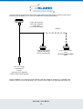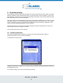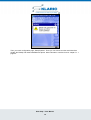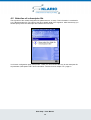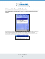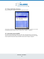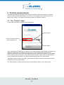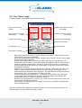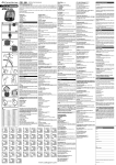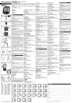
1
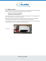
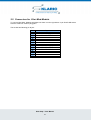
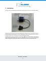
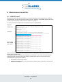
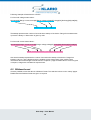
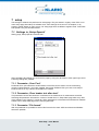
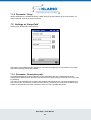
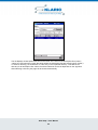
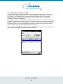
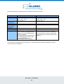
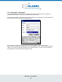
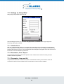
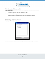
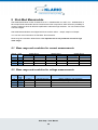
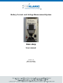
Battery Current- and Voltage Measurement-System
Klari-Amp
User manual
Version: 0.5
Date: 27.10.2004
Autor: Martin Hötger
History
Version
0.1
0.2
0.3
0.4
0.5
Date
10.11.2003
26.11.2003
02.12.2003
09.01.2004
27.10.2004
Autor
Mho
Mho
Mho
Mho
Mho
Description
First release
chapter „operating elements and connectors“ inserted
trademark measurement modul darkened
Reinserted Trademark
Renamed to Klari-Amp. Software version 1.05 and later
Table of content
1
INTRODUCTION
4
2
OPERATION ELEMENTS AND CONNECTORS
5
2.1
Battery monitor
6
2.2
Operation mode „Measurement“
7
2.3
Betriebszustand „Laden“
7
2.4
Holdings PDA
7
2.5
Connectors for Klari-Mod-Module
8
3
INSTALLATION
4
COMMISSIONING
11
4.1
Initial connection
11
4.2
Selection of a descriptor file
13
4.3
Auswahl der Messmodul-Konfiguration
14
4.4
Setup destination directory
15
4.5
Information about datafile
15
PERFORM MEASUREMENTS
16
5
9
5.1
The “Control” page
16
5.2
The “Show” page
17
6
6.1
MEASUREMENT RESULT FILE
18
ASCII-Format
18
Klari-Amp – User Manual
2
6.2
7
DIAdem-format
19
SETUP
20
7.1
Settings in ‚Setup-Special’
7.1.1
Parameter „Com. Port“
7.1.2
Parameter „Clear header text after start“
7.1.3
Parameter “File format”
7.1.4
Parameter “Delay”
20
20
20
20
21
7.2
Settings at ‚Setup-Path’
7.2.1
Parameter „Description path“
7.2.2
Parameter „Sensor config“
7.2.3
Parameter „Data path“
21
21
23
25
7.3
Settings at ‚Setup-Data’
7.3.1
Header-lines
7.3.2
Parameter „Desc. Separ.“
7.3.3
Parameter „Lines per file“
7.3.4
Parameter „Filename prefix“
26
26
26
26
27
7.4
Settings at “Setup-Analog”
27
KLARI-MOD MEASMODULE
28
8
8.1
Meas range and resolution for current measurements
28
8.2
Meas range and resolution for voltage measurements
28
Klari-Amp – User Manual
3
1 Introduction
Klari-Amp is a system to measure and record electrical current and electrical voltage. It is used mainly
in vehicle environment. It is thinkable to use also in other environments like solar devices. The system
consists of three components :
1. current and voltage meas module Klari-Mod (meas module)
2. The supply- and record unit based on a PDA (base unit)
3. a cable tree to connect the components.
The measurement modul of type Klari-Mod contains a current meas shunt and an input for voltage
meas. It could be configured via serial interface (RS232). There are a lot of setups related to data rate
etc. possible. More deeper information could be found in Klari-Mod documentation. Measurement are
also send via serial interface. There are Klari-Mod -Modules with different resistor values or current
meas ranges. More information in chapter 8 page 28.
The base unit consist mainly of a 12 V accumulator and a PDA, that are mounted in one housing. 12 V
accu supplies PDA and measurement module (over cable tree). On PDA is installed Klari-Amp
software.This software is responsible fort he configuration of the measurement modul by using a
configuration file. It collects the values of the meas module and calculates a loading balance (Ah
counter). All meas values are displayed by software and stored in an ascii file. Storage destination
could be any storage type of the PDA, e.g. SD card or a CF card.
Klari-Amp – User Manual
4
2 Operation elements and connectors
In this chapter will be described the operating elements and connectors of the base unit. After opening
the cover you find following components :
PDA with Klari-Ampsoftware
PDA-holding
LED of the battery monitor
Switch for operation mode:
„Meas“ or „Load“
Key of the battery monitor
At the side are following connectors :
Loading socket:
Red = Plus,
Blue = Minus
(14.4 V / 800mA)
Additional sockets for
external connection of the
PDA
15pin. Sub-D-HDsocket
connection to
Klari-Mod-Module
Klari-Amp – User Manual
5
2.1 Battery monitor
With help of the key on the left side of the front plate you could activate the battery monitor. By holding
pressed the key you could monitor the Loading state of the 12V accumulator :
-
LED is dark: Accu empty, load immediate
LED is red: Accu nearly empty. Load soon
LED is green: Accu loading state is ok
The remaining operation time could not be seen by display. It is dependent of accus history. But with a
green LED a measure time of 24h should be possible.
Battery monitor is active, independent of the operational mode of the base unit. But it shouldn’t be
used to stop a loading session. For more information to load an accu see chapter 2.3.
If the LED is dark and no loading of the accu is possible the fuse may be blown. In this case check the
fuse and probably replace it. To change the fuse open the base unit :
Fuse holder
Klari-Amp – User Manual
6
2.2 Operation mode „Measurement“
Using the switch on the right side of the front plate the operation mode „measurement“ could be
activated.
This means the PDA and an externally connected Klari-Mod-Module are supplied of 12V accu. If you
want to measure with Klari-Mod-System then the base unit has to be driven in this operation mode. If
you switch into this state, or a Klari-Amp-Modul in this state is connected with the base unit it may bet
hat PDA will try to connect to a host PC. Terminate this trial always. Only in this case Klari-AmpSoftware can access serial interface.
In this state loading sockets are disabled. Loading the accu at the same time is not possible.
2.3 Betriebszustand „Laden“
Using the switch on the right side of the front plate the operation mode „loading“ could be activated.
In this state the supply of the PDA and an externally connected Klari-Mod -Modul is disabled. The
PDA uses its internal accu. The loading sockets are connected via a diode with the internal accu. To
load the accu you should use a supply with current limitation. You shoud setup the supply before it’s
connected to the loading sockets !
-
voltage: 14.5 V
maximal current: 800mA
Pay attention off the proper connectio. Red socket = plus and blue socket = minus. Loading session is
finished when the current is less than 30mA.
2.4 Holdings PDA
Before removing PDA you should unscrew the holding. There is a small lever on PDA’s left side. This
could be damaged when you try to remove PDA without dismounting the holding !
Klari-Amp – User Manual
7
2.5 Connectors for Klari-Mod-Module
To connect Klari-Mod -Modules with base unit there is on the right side a 15 pin Sub-D-HD socket.
Here the cable tree must be plugged in.
The socket has following pin layout :
Pin
1
2
3
4
5
6
7
8
9
10
11
12
13
14
15
Signal
Klari-Mod -supply GND
PDA-RS232 GND
PDA-RS232 DTR
Klari-Mod -supply +
PDA-RS232 RxD
PDA-RS232 TxD
Klari-Amp – User Manual
8
3 Installation
First you should install Klari-Mod -Measmodule. Following photo shows such a Klari-Mod -Modul:
Connectors for current measurement
(GND for measurement)
15 pin. Sub-Dconnector with
meas, data and
supply lines
With the two connectors the current meas module will be inserted into the current loop. There are
different adapters available (pole connectors, brass poles, cable lug). Note that the left connecter
where the cable comes out represents the internal GROUND potential.
Attention! This connector is directly connected to GND of the serial interface.! Pay attention
not to create a short circuit! This could bet he case when you connect the module at the positive
battery pole and then a PDA supplied from the same battery without a potential interruption.
Klari-Amp – User Manual
9
Via 15-pin Sub-D connector the cable fort he base station will be connected. There are cable trees in
different length available (2 m or 4 m). The cables have at least following lines :
15 pin, Sub-D-socket
with meas, data and
supply lines
(connect to Klari-Mod)
optional
15 pin. Sub-D-HD-pin
RS232 and supply
(connect to base unit)
9 pin. Sub-D-socket
CAN
(do not connect to base
unit)
Line for voltage
mearuement
(violet)
reference ist he internal
GND of Klari-Mod-Module
During installation you connect the violet meas line with the voltage to measure (e.g. pluspole of the
battery in vehicle). 15 pin Sub-D-HD-pin you connect to the socket on the right side of the base unit.
Klari-Amp – User Manual
10
4 Commissioning
After installing of meas module, cable and base unit the first commissioning of the system could start.
Switch to operation mode “measurement mode” by using the switch on the front plate. In some case
PDA searches a connection to a host PC after switching on this state. This has to be aborted to allow
Klari-Amp-Software to access serial interface.
Then Klari-Amp.exe will be started first time on PDA. The software is delivered on CF-card. It‘s inside „
Klari-Mod “ directory. You can start this program directly there.It’s more easy to launch out of “Start
menu“ of the PDA. To do so you should copy file „Klari-Amp.exe“ from directory „ Klari-Mod “ of CFCard to „My device/Windows/Startmenu“ (if not yet done).
After the first start up you should do some base settings that could be changed later at every time.
This settings are stored in registry of the PDA.
The procedure after start up is the following :
4.1 Initial connection
After start up software tries to establish a connection via serial RS232-interface COM1 to
measurement module. There are two possibilities :
A measmodule could be found :
In diesem Beispiel wird ein Messmodul mit der Signatur 0x00010205 erkannt. Anhand der Signatur ist
festgelegt, um welche Art Modul es sich handelt, welche Parameter dieses Modul besitzt und wie sie
zu programmieren sind.
If no module could be found you will see following message :
Klari-Amp – User Manual
11
Then you reach configuration page „Setup-Special“. There you can choose an other serial interface
(COM1 bis COM9) and restert establishment phase. More information could be found in chapter 7.1.1
page 20.
Klari-Amp – User Manual
12
4.2 Selection of a descriptor file
The signature of the module designates the parameters etc. to setup. This information is contained in
a so called descriptor file. The name of the file is partially build of the signature. After first start up you
should specify where this descriptor file could be found on PDA :
You’ll reach configuration page „Setup-Path“. There you can enter the directory for the descriptor file
as parameter „Description Path“. More information could be found in chapter 7.2.1 page 21.
Klari-Amp – User Manual
13
4.3 Auswahl der Messmodul-Konfiguration
Klari-Mod-Module is an universal device to perform multiple kinds of measurements. There are a lot of
parameters to do that. To help the user to configure his Klari-Amp-Measurement-System CF-card
contain already different configuration files on delivery. So one of them could be the base of users
application :
After pressing „Ok“-Buttons you reach „Setup-Path“ page. Using the parameters „Sensor config“ you
could select a configuration file. More information could be found in chapter 7.2.2 page 23.
After selecting a configuration file the meas module will be setted up. This may take a short while.
During this time a WAIT message is displayed in the title of the frame :
Klari-Amp – User Manual
14
4.4 Setup destination directory
Next you’ll be asked for a destination directory for measurement results :
After pressing „Ok“-Buttons you reach „Setup-Path“ page. Using parameter „Data path“ you can enter
the destination directory. More information could be found in chapter 7.2.3 page 25.
4.5 Information about datafile
After setting up most important directories you’ll reach again „Setup-Data“ page. This is always the
case not only during the first startup. At this page you can enter header line information for the ASCII
file and a prefix for the file name. More information could be found in chapter 7.3 page 26.
Klari-Amp – User Manual
15
5 Perform measurements
After startup and leaving setup page you’ll reach main window of Klari-Amp-Software. The main
window consists of three different pages. To select one of the pages use the page-register at the
bottom of the window. The pages are described in detail in the following chapters.
5.1 The “Control” page
On this page you find the controls for the measurement:
„Reset“-Button
“Start“ and „Stop“- Button to
control measurement
„Setup“-Button
Using „Start“-Button a measurement is started. A new meas result file will be created and header lines
defined in „Setup-Data“ are inserted. After that for every new measurement a new line will be
appended The received meas values are displayed on screen. Note that the display is not so fast like
the real storage. During recording no setup data could be changed. „Setup“-Button is deactivated. A
running measurement recording is visualized by a black background of the „Start“-Button.
„Stop“-Butten will terminate the recording. Measurement file will be closed. Now setup data could be
changed by pressing „Setup“-Button.
The “Reset”-Button is used zu reset the minimum and maximum values on the “Show”-page.
Klari-Amp – User Manual
16
5.2 The “Show” page
This page displays all measured values during a recording.
range for current and
voltage
measurement value for current
and voltage
minimum value of current
and volateg
maximum value for current
and voltage
Ampere-hours (load)
Ampere-hours (discharge)
Ampere-hours (total)
Timestamp (in sec.)
Received frames
Free space on storage
-
-
-
-
Range and measurement value of current: „Range I“ and „Value I“. Here the actual current
value and the actual range is displayed.
Range and measurement value of voltage: „Range U“ and „Value U“. Here the actual voltage
and the actual range is displayed.
Minimal- and maximal value of current and voltage: „Minimum I/U“ and „Maximum I/U“.
Minimal and maximal values of current and voltage are displayed here. The values could be
resetted by pressing „Reset“-Button, also during measurement recording. It is possible to
specify a delay time for the reset on the “setup”-pages. In this case, the reset don’t happen
immediately but delayed.
Ampere-hours for charge, discharge and total sum: „Charge“, „Discharge“ and „Total“. The
positive current measurements are integrated in in field „Charge“. The negative current
measurements are integrated in field „Discharge“. The arithmetical sum of this two values is
shown in field „Total“. A charge scale o. or other is not used.
Timestamp of last current measurement : „Timestamp“. The timestamp of the last single
current measurement is displayed in seconds. This time is related to the startup of the
software after switch on. It will be resetted after switch off.
Number of the received frames: „Frames“. The number of received frames since start of the
measurement is displayed in this filed.
Free memory of the storage device: „Free MB“. The amount of free MB on actual storage
device is displayed here
Using the „Ok“-Buttons the application will be terminated. An evtl. Running measurement will be
stopped and the the measurement result file is closed.
Klari-Amp – User Manual
17
6 Measurement result file
6.1 ASCII-Format
Measurement values are stored as ASCII in csv-format. Each day a new subdirectory is created in
meas data path. The filename is build of „Filename prefix“, defined in „Setup-Data“ and the time of file
creation. More information could be found in chapter 7.3.4 page 27.
On every received meas data frame is created a new line in meas data file
Example:
Header-lines
Table-Info
Meas values
blue: voltage
red: current
Klari-Amp Unlicensed Version, only for evaluation!
Version V1.01, (c) Fa. Klaric GmbH & Co. KG
vehicle;test car 1
Date;10.11.2003
Name;mho
div;Test Klari-Amp
timestamp[s];Range current;current[A];Range
voltage;voltage[V];charge[Ah];discharge[Ah];total[Ah]
20285.1660;;;1;0.002;;;;
20285.2109;3;-0.005;;;0.000;0.000;0.000;
20286.3105;;;1;0.002;;;;
20286.3555;3;-0.005;;;0.000;0.000;0.000;
20287.4570;;;1;0.002;;;;
20287.5020;3;-0.005;;;0.000;0.000;0.000;
20288.6016;;;1;0.002;;;;
20288.6465;3;-0.005;;;0.000;0.000;0.000;
20289.7480;;;1;0.002;;;;
20289.7930;3;-0.005;;;0.000;0.000;0.000;
20290.8926;;;1;0.002;;;;
20290.9375;3;-0.005;;;0.000;0.000;0.000;
20292.0391;;;1;0.002;;;;
20292.0820;3;-0.005;;;0.000;0.000;0.000;
20293.1836;;;1;0.002;;;;
20293.2285;3;-0.005;;;0.000;0.000;0.000;
The informations of the header lines could be entered in „Setup-Data“, also decimal delimiter of meas
values (here: decimal point).
The single columns of a result line are separated by a semicolon. The content of the columns are
described in table info lines. Only those columns are filled when there is a new meas or a new
calculated result. There are two reasons :
1. saves space on the storage device
2. Artefacts (stair steps) in the curves are avoided. Artefacts will be created when inserting old
values in the coulumns.
Klari-Amp – User Manual
18
Following example will describe the columns :
For lines with voltage meas values :
timestampl[s];Range current;current[A];Range voltage;voltage[V];charge[Ah];discharge[Ah];total[Ah]
20285.1660;;;1;0.002;;;;
Timestamp represents the number of seconds since startup of the device. Range for measurements
up to 20V is always 1. Meas value is given by volts.
For lines with current meas values :
timestamp[s];Range current;current[A];Range voltage;voltage[V];charge[Ah];discharge[Ah];total[Ah]
20285.2109;3;-0.005;;;0.000;0.000;0.000;
Also here timestamp represents the number of seconds since startup of the device. Range lies
between 0 and 3. 0 is the biggest and 3 the smallest current meas range of the module. More
information about meas ranges could be found in chapter 8.1 page 28. Meas value of current is given
in Ampere, charges are calculated in Ampere hours.
6.2 DIAdem-format
It is also possible to store the data in a DIAdem-Format. The selection is done on the “setup”-pages.
Details about the DIAdem-format are given on request.
Klari-Amp – User Manual
19
7 setup
The settings of software are performed on setup page. They are stored in registry of the PDA. You’ll
reach setup page after starup of software when some settings are incorrect or incomplete, or by
pressing „Setup“-Button on main screen. On setup page there are different register cards : Data, Path
and Special. They are described below.
7.1 Settings in ‚Setup-Special’
Setting page „Setup-Special“ looks like that :
After completing all settings you can leave the page by using the „Ok“-Button at the upper right corner.
Following settings are possible :
7.1.1 Parameter „Com. Port“
Parameter Com. port selects the serial interface of the PDA, that is used to connect measuring
module. Values between 1 and 9 are possible. Using Axim X5 Basic PDA you have to use alwys 1
because this ist he only interface accessible from outside.
7.1.2 Parameter „Clear header text after start“
This parameter controls the behaviour of software fort he header lines of measurement result file.
Activating this parameter will erase the content of header lines in „Setup-Data“ page after every start
of the software. (see chapter 7.3 page 26). When parameter is not activated the software will maintain
header lines of setup data page fort he next program start.
7.1.3 Parameter “File format”
With this parameter it is possible to select a file format for the data. ASCII-text-format and DIAdemformat are possible.
Klari-Amp – User Manual
20
7.1.4 Parameter “Delay”
Wit this parameter it is possible to specify a delay time for the reset-button on the main window. If a
delay is desired, it has to be given in minutes.
7.2 Settings at ‚Setup-Path’
Setting page „Setup-Path“ looks like that :
After setting up all parameters like wished you can leave this page with the „Ok“-Button on the upper
right side. Following settings are possible :
7.2.1 Parameter „Description path“
This parameter defines the source directory for the description files of the measurement modul.
Description file defines which parameter are relevant for the measurement module and how they could
be setted up.
The name of the description file is build of the signature transmitted during connection establishment
with meas modul. The directory couldn’t be setup directly. Instead of you could press the button right
beside the text field and you reach a dialog to select one of the possible directories.
Klari-Amp – User Manual
21
The list displays all description files found in the PDA. The names of the description files (column
“name”) are not important, but the directories where the description files are stored (column “folder”).
To select a directory you should klick on a file entry in the requested directory. This defines the
directory for all description files. Which file will be loaded at runtime is dependent on the signature.
After selecting a directory the page will be closed automatically.
Klari-Amp – User Manual
22
7.2.2 Parameter „Sensor config“
This parameter defines the configuration fort he operatation during measurement. To define the
configuration you should select on of the list. A couple of cofigurations are shipped on CF-Card. You
can create such y configuration file by using configuration tool KoWin. But you’ll need a deep
knowledge of Klari-Mod -Firmware. On request co. Klaric GmbH & Co. KG can customize the
configuration file for a user application.
The configuration files are used because of following reason: Firmware of Klari-Mod -Measmodul is
scalable for a lot of different measurement jobs. This results in a big number of settings. With the help
of configuration files the user can use all features by creating different profiles by himself. For daily
measurement jobs you can used predefined configurations. In this way the meas modul is always
proper configured. Errors and bad measurements are minimized.
The selection of a configuration files is done with the help of the button right beside text field „Sensor
config“. After pressing the button following window is displayed:
Klari-Amp – User Manual
23
As standard following configuration files are shiped for vehicle environment:
configuration
Name
Mean calc.
Datarate
valuepairs/sec.
Dead time-relation
Sampling period
(Reaction time,
autorange)
Size
Runtime 512MB
Description
Small dead time
SHORT_DEADTIME
Ext_Ave = 1
Chan_I_Ave = 1024
Chan_A_Ave = 1
15
Short reaction time
SHORT_TS
Ext_Ave = 8
Chan_I_Ave = 128
Chan_A_Ave = 1
14
1,3 %
66 ms
9,6 %
9 ms
4,5MB/h
4,75 days
This configuration represents a good
relation of meas or integration time to
total time for current measurements.
(dead time relation)
This config is good for measurements
where charging balance with small
currents is impolrtant, (e.g.
measurements of base currents).
4,1MB/h
5 days
The desd time relation in this configuration is
worst, but the reaction time on autorange
events is better.This config is good if base
currents and starter current are measured in
sequence.
You can select a configuration file by klicking on it. The window will be closed automatically and meas
module could be reconfigured.
Klari-Amp – User Manual
24
7.2.3 Parameter „Data path“
This parameter defines root directory for measurement storage. Inside this directory subdirs are
created by a date relation. There are stored measurement value files.
The selection of root directory is done by pressing the button on the right side of text field „Data path“.
After pressing this button is displayed following window:
In this window you define the root directory with the help of fileds „Location“ and „Folder“.
With „Location“ you select the storage device, e.g. main storage of PDA , CF-Card or SD-Card. With
„Folder“ you can specify optionally a subdir in these storage devices. You have to notice that KlariAmp-Software will create date related subdirs by itself.
Klari-Amp – User Manual
25
7.3 Settings at ‚Setup-Data’
Setup page „Setup-Data“ looks like that :
After all settings are done you can leave the page with the „Ok“-Button on the upper right side.
Following settings are possible :
7.3.1 Header-lines
With the 4 described text fields you can specify the header lines that are inserted in a measurement
file. It is possible to modify the text in the input frames. In addition you can change the descritption by
pressing with the pen on them. In the measurement files description will appear in the first column and
the text in the second devided by semicolon.
7.3.2 Parameter „Desc. Separ.“
This parameter specifies the decimal separator of the measurement values. Decimal point and
decimal comma are possible.
7.3.3 Parameter „Lines per file“
This parameter defines the maximum number of measurement values per file. When a files will
contain this number of meas values the file is closed and a new one will be created.
Klari-Amp – User Manual
26
7.3.4 Parameter „Filename prefix“
This parameter will influance the names of meas value files. Basically measurement values are stored
in date related subdirs :
„yyyy-mm-dd“ with yyyy = year, mm = month and dd = day.
File names are build of „Filename prefix“ and actual time:
„<Filename_prefix>-hh-mm-ss.txt” with hh = hour, mm = minute and ss = second
7.4 Settings at “Setup-Analog”
Setup page „Setup-Analog“ looks like that :
With this checkboxes it is possible to invert the analog channels, i. e. change the sign of the values.
Klari-Amp – User Manual
27
8 Klari-Mod Measmodule
Klari-Mod Measmodule consist of Meas-Shunt of co. Isabellenhütte, an ASIC of co.. Isabellenhütte, a
Microchip-PIC-Microkontroller and div interfaces and other components. ASIC offers the possibility to
measure voltage at shunt at different amplification scales with high resolution. You can measure other
external voltages.
Klari-Mod Measmoduleare are shipped with three resistor values. : 100µO, 200µO und 500µO.
You can find more informations in Klari-Mod -Documentation.
Meas range and resolution alisted below. It is important not to use permanent current for high
meas range!
8.1 Meas range and resolution for current measurements
Range
0
1
2
3
PGA
Gain
4.8
24
50
100
100µO-Shunt
Meas range
resolution
+/- 1500A
45.7764 mA
+/- 300A
9.15527 mA
+/- 150A
4.57764 mA
+/- 75A
2.28882 mA
200µO-Shunt
Meas range
resolution
+/- 750A
22.8882 mA
+/- 150A
4.57764 mA
+/- 75A
2.28882 mA
+/- 37.5A
1.14441 mA
500µO-Shunt
Meas range
resolution
+/- 300A
9.15527 mA
+/- 60A
1.83105 mA
+/- 30A
0.915527 mA
+/- 15A
0.457764 mA
8.2 Meas range and resolution for voltage measurements
Range
0
1
2
3
PGA
Gain
4.8
24
50
100
Meas range
resolution
Description
+/- 60 V
+/- 20 V
+/- 10 V
+/- 5 V
3.051757813 mV
0.6103515625 mV
0.3051757813 mV
0.1525878906 mV
Battery voltage in 42V systemen
Battery voltage in 12V systemen
Not used
Not used
Klari-Amp – User Manual
28