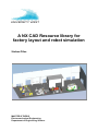
1
A NX CAD Resource library for factory layout and robot simulation Stefaan Pillen MASTER’S THESIS Electromechanical Engineering Department of Engineering Science MASTER’S THESIS A NX CAD resource library for factory layout and robot simulation Summary Online programming, manually teaching a robot a trajectory by a pendent, is a very time consuming and costly job. Another approach should be considered in order to remain competitive with the low-wage countries. A solution for this could be found in offline programming. Offline programming gives the possibility to program the robot from the comfort of a personal office. This could be done while the robot is being installed, reducing the start-up time dramatically. By reducing the start-up time, the costs are cut as well. In order to program offline properly, an accurate model of the robot cell, preferably the whole machine hall, has to be available. The goal of this thesis was to find a way to program offline with the help of Siemens NX. Not directly doing the offline programming with NX but first creating a resource library, adding kinematics to the models, creating a robot simulation, and then transferring this to Process Simulate in order to load the program to the robot. This thesis project reflects on the possibilities to program offline with NX, and highlights the numerous problems that occurred. It includes a solution for the encountered problems, making use of the possibilities of Process Simulate. A user manual that serves as a guideline to add kinematics in NX has been added in the appendix to help getting the reader started with motion simulation in NX. Author: Examiner: Advisor: Programme: Subject: Date: Keywords Stefaan Pillen Dr. Fredrik Danielsson MSc. Anders Appelgren Electromechanical Engineering Master’s thesis Engineering Level: Advanced level Mai 21, 2012 Offline programming, Siemens NX, Process Simulate, Library, Factory Layout, Robot Simulation, Laserscanning, Kinematics, Motion Simulation, Accuracy Publisher: University West, Department of Engineering Science, S-461 86 Trollhättan, SWEDEN Phone: + 46 520 22 30 00 Fax: + 46 520 22 32 99 Web: www.hv.se ii A NX CAD resource library for factory layout and robot simulation Preface To complete my masters in industrial engineering, I wrote my master’s thesis on creating a NX CAD resource library for factory layout and robot simulation. But as a student, an Erasmus student in a foreign country, it is hard to solve a difficult problem by your own. So the help of experienced people was very welcome. That is why I would like to thank the necessary people in this way. First of all I would like to thank my parents, they have made the effort so I could study and complete my masters. I would also like to thank my promoter Ir. Monserez, my advisor MSc. Appelgren and my examiner dr. Danielsson. With their help, this thesis has become what it now is. My teaching staff at the KHBO and University West. They were always ready to help me with some questions. Also many thanks go to my girlfriend Eva Vermeire, my family and friends, for the needed support to complete this project. For me, going on Erasmus and finishing my masters abroad, was a broadening experience and a great closing to my master’s program. iii A NX CAD resource library for factory layout and robot simulation Contents Summary ............................................................................................................................................... ii Preface.................................................................................................................................................. iii Contents............................................................................................................................................... iv List of symbols ................................................................................................................................... vi List of figures .....................................................................................................................................vii List of tables .......................................................................................................................................vii 1 Introduction .................................................................................................................................. 1 2 Background information ............................................................................................................. 2 3 Litarature study ............................................................................................................................. 2 3.1 Robot simulation ................................................................................................................... 2 3.2 Offline programming ............................................................................................................ 3 3.3 Siemens NX ............................................................................................................................ 3 3.4 Process Simulate .................................................................................................................... 3 3.5 Laserscanning ......................................................................................................................... 4 3.5.1 Accuracy ........................................................................................................................ 4 3.5.1.1 Accuracy of 3D Laser scanning .................................................................... 5 3.5.1.2 Accuracy of distance measurements ............................................................ 6 3.5.1.3 Accuracy of inclination compensation ........................................................ 7 3.5.1.4 Influence of the laser beam’s angle of incidence on 3D accuracy .......... 7 3.5.2 Reflections .................................................................................................................... 8 3.6 Manual measuring .................................................................................................................. 8 3.7 Robot measuring .................................................................................................................... 8 3.8 Draw wire displacement ....................................................................................................... 9 3.9 JT file .....................................................................................................................................10 4 Library in NX..............................................................................................................................10 4.1 Accuracy ................................................................................................................................11 4.2 Structure ................................................................................................................................13 4.3 Kinematics ............................................................................................................................15 5 Transferring NX library to Process Simulate ........................................................................15 6 Library in Process Simulate ......................................................................................................17 6.1 The operation library...........................................................................................................17 6.2 The station resource library ...............................................................................................18 6.2.1 Robot ...........................................................................................................................19 6.2.2 Fence............................................................................................................................19 6.2.3 Fixture .........................................................................................................................19 6.2.4 Equipment ..................................................................................................................19 6.2.5 Device ..........................................................................................................................19 6.3 The part library.....................................................................................................................19 iv A NX CAD resource library for factory layout and robot simulation 6.4 The resource library.............................................................................................................20 6.4.1 Fixture .........................................................................................................................20 6.4.2 FPack ...........................................................................................................................20 6.4.3 FPack components ....................................................................................................21 6.4.3.1 Cable packages ...............................................................................................21 6.4.3.2 Positioners ......................................................................................................21 6.4.3.3 Robots .............................................................................................................21 6.4.3.4 Spindels ...........................................................................................................21 6.4.3.5 Tool changer ..................................................................................................21 6.4.3.6 Track motion .................................................................................................21 6.4.3.7 Gripper............................................................................................................21 6.4.3.8 Guns ................................................................................................................22 6.4.3.9 Robot base......................................................................................................22 6.4.4 Station equipment......................................................................................................22 6.4.4.1 Fence ...............................................................................................................22 6.4.4.2 Equipment ......................................................................................................22 6.4.4.3 Device .............................................................................................................22 6.4.4.4 Conveyer .........................................................................................................22 6.4.4.5 Sensor ..............................................................................................................22 6.4.4.6 Robot cabinet.................................................................................................22 6.5 The study folder ...................................................................................................................23 7 Simulation ....................................................................................................................................23 8 Conclusions .................................................................................................................................25 References ..........................................................................................................................................26 Appendices A. User manual for kinematics v A NX CAD resource library for factory layout and robot simulation List of symbols 3D Three-dimensional ATV Automated transfer vehicle CAD Computer Aided Design CAE Computer Aided Engineering CAM Computer Aided Manufacturing GPS Global Positioning System OLP Offline Programming PLM Product Lifecycle Management TBM Time Based Measuring VAC Volvo Aero Corporation VCC Volvo Car Corporation vi A NX CAD resource library for factory layout and robot simulation List of figures Figure 1: Overview of the process Figure 3.5.1.1: Distribution of differences between scanned distances and reference distances, from [7] Figure 3.5.1.2: Comparison of the differences between scanning and reference distances, from [7] Figure 3.5.1.3: Test of inclination sensor: Differences between scanned spheres and horizontal XY plane, from [7] Figure 3.5.1.4: Influence of angle of incidence, from [7] Figure 3.8: Draw wire displacement sensors Figure 4.1: Accuracy Figure 4.2-1: Lean cell Figure 4.2-2: The assembly of the fence Figure 4.2-3: A part of the fence Figure 5-1: Export to JT Figure 5-2: Import JT Figure 6: Overview structure Figure 6.1: The operation library Figure 6.2: The station resource library Figure 6.3: The part library Figure 6.4: The resource library Figure 7-1: Simulation Lean cell Figure 7-2: PTC line List of tables Table 1: Summary of technical specifications according to the manufacturer, from [7] Table 2: Comparison of 3D distances between laser scanner and reference in the 3D test field, from [7] Table 3: Simulation requirements, from [2] Table 4: Installation requirements, from [2] vii A NX CAD resource library for factory layout and robot simulation 1 Introduction Online programming [3] is a very time consuming and costly job. A solution for this is offline programming (OLP). OLP [10] can reduce the start-up time dramatically [4], and by reducing the start-up time, the costs are cut as well. To be able to program offline, an accurate model has to be available. This thesis will focus on the possibilities on how to use Siemens NX as a base for 3D models. These models will be used for purposes such as OLP. The idea is not to use NX directly for the OLP, but first transfer the model with kinematics from NX to Process Simulate which is a dedicated software for robot simulation and OLP. From the OLP the robot programme can be downloaded to the real robot, see figure 1. Figure 1: Overview of the process To be able to transfer the CAD library made in NX to Process Simulate, which is the central theme of the thesis, the library should be accurate enough for OLP. Chapter 3.1 will go deeper into the needed accuracy. If kinematics is added to the models, it is necessary that the kinematics can be transferred to Process Simulate. The library should also contain a certain structure, this structure should be user friendly and synoptic. It is important that the structure remains the same after transferring the library. This would make it possible to easily retrieve a single component, as well as the whole assembly, import and export components and assemblies into other programs and use the library for many other purposes. In general the thesis will concentrate more on the modelling for OLP rather than the actual OLP. The modelling consists of creating an accurate model, adding kinematics in NX and transferring the model to Process Simulate. 1 A NX CAD resource library for factory layout and robot simulation 2 Background information This thesis focusses on the possibilities on how to use Siemens NX as a base for 3D models. The central theme is transferring the CAD library made in NX to Process Simulate. This can be of importance for factory layout, robot simulation, offline programming,… The key of a useful library, is a good structure. A good structure makes it possible to retrieve assemblies, objects and parts in a fast and easy way. This decreases the searching time and by doing so, costs are cut as well. This work should give the reader an idea of how to create the models in a structured way. Creating the structure from the beginning makes it easier to obtain a good structure. 3 Literature study 3.1 Robot simulation Instead of buying an expensive robot and doing the testing with this robot, a robot simulation can be made. With the simulation extensive testing of the robot and its functions can be done without any chances of injuries or damage. [17] A fast process can be slowed down to observe the actions in slow motion, by this optimizing the cycle time. By doing extensive testing, necessary changes after constructing the robot cell, can be minimized, saving huge amounts of time and resources. [4] Robot simulation makes it possible to study the structure, characteristics and the function of a robot system at different levels of details, each posing different requirements for the simulation tools. As the complexity of robotics increases, robot simulation becomes more and more important. In short: robot simulation is used to figure out what the best robot is to use, to verify the reach and access of the robot, to configure the tooling and equipment around the robot. It is used as a quicker and simpler method for testing out ideas, theories and software. [17] 2 A NX CAD resource library for factory layout and robot simulation 3.2 Offline programming Manual online programming [3] refers to teaching a robot a trajectory by a pendent. This kind of programming has some disadvantages: it is very slow, could take weeks, needs the robot to be available, and requires an operator with knowledge of the specific robot language and the used equipment. These actions stop the production for a long time, therefore it is very expensive. A solution could be found in Offline programming (OLP). [10] OLP refers to the ability to program your robot from a computer instead of at the robot itself. So the programmer can do the programing from his comfortable office. [15] In able to program, the 3D models of both the entire cell and the products in process should be available. Once the 3D models are acquired, a virtual work floor can be created. In most cases the existing CAD data can be used for the programming. Now the robot process can be built with the computer. The OLP makes it possible to program the process during the welding of the cell, reducing the start-up time tremendously. The expensive robot will be used at its full potential, not standing idle during programing. [9] Also the OLP itself is a lot faster than jogging the robot around in the cell. Instead of losing weeks, the whole programming can now be done in a few days. 3.3 Siemens NX Siemens NX is an advanced CAD/CAM/CAE software package, developed by Siemens PLM software. [12] It helps making an engineer focus more on the engineering part of the job, than on the designing part. This way the engineer can fully focus on his real job, instead of on the time consuming parts. Siemens NX is developed for industrial design and styling, package design, mechanical design, electromechanical design, mechatronics concept design, mechanical simulation, electromechanical simulation, tooling and fixture design, machining and quality inspection. [14] It is possible to use Siemens NX for other purposes as well. 3.4 Process Simulate Process Simulate [1], a product of Siemens, has been developed to manufacture process verification in a 3D environment. Most often it is not the starting point. The project layout, libraries, connections, resources etc. are created in another application such as Process Designer. The usual work order is: opening a new study, creating an operation, creating a sequence of operations, analysing and modifying a path and outputting deliverables and collaboration. 3 A NX CAD resource library for factory layout and robot simulation 3.5 Laser scanning Because of the vast use of 3D laser scanning to make a 3D model, a brief statement of the basics of laser scanning systems is at its place. Laser scanning refers to a method of measuring a point cloud using laser technology. [12] The acquired data can then be used to create a digital 2 or 3D model. There are 2 ways to declare the coordinate system, by indirect registration and by direct registration, for more details see reference [16]. The advantage of laser scanning is the ability to measure a huge amount of points with a high accuracy within a short time span. The laser scanning technology can be divided in two; the static and the dynamic laser scanning. Scanning from a fixed location is called static laser scanning. This type of scanning is more accurate. Static laser scanning is of importance for OLP. When the scanner is mounted on a mobile platform, it is called dynamic laser scanning. Additional positioning systems, like GPS, are necessary. There are two main methods of scanning; measuring with triangulation and time based measuring (TBM). TBM is the most important method for OLP, and can be divided into pulse based (time of flight) and phase based scanners. In general the phase based scanners are faster but less accurate than the pulse based scanners. [16] A comparison of the most used laser scanners and their accuracy, based on [7], will be discussed in detail in the following section 2.5.1. 3.5.1 Accuracy The following laser scanners have been investigated: Trimble GX, Leica ScanStation 1, Leica ScanStation 2, Leica HDS 6000, Faro LS 880, IMAGER 5006 from Zoller & Fröhlich, and RIEGL LMSZ420i. Most of these scanners use spheres to obtain the reference positions. The diameter of the used sphere is 145mm. A summary of the specifications according to the manufacturers: 4 A NX CAD resource library for factory layout and robot simulation Scanner Trimble GX Scan Time of method flight based Field of view (°) 360 x 60 Scan distance (m) 350 Scanning speed (pts/sec) ≤5000 Angular V 0,0018 resolution (°) H 0,0018 3D scan precicsion 12mm/100m Camera Inclination sensor integrated Leica ScanStation 1 Time of flight based Leica ScanStation 2 Time of flight based Riegl LMSZ420i Time of flight based FARO LS 880 HE Phase based Phase based 360 x 270 360 x 270 360 x 80 360 x 320 360 x 310 300 300 1000 <76 <79 ≤4000 0,0023 ≤50000 0,0023 ≤11000 0,002 ≤120000 0,009 ≤500000 0,0018 0,0023 0,0023 0,0025 0,00076 0,0018 6mm/50m 6mm/50m integrated integrated Z+F IMAGER 5006 10mm/50m 3mm/25m 10mm/50m add-on add-on add-on option option option compensator compensator compensator compensator yes yes Table 5: Summary of technical specifications according to the manufacturer, from [7] If the scan speed and the scan distance are compared, it is clearly that the phase based scanners are much faster, but measure shorter distances. 3.5.1.1 Accuracy of 3D Laser scanning Using the sphere with a diameter of 145mm, the following results were obtained from a controlled test with 53 reference points which can be set up with prisms, spheres or targets [7]: Scanner Leica ScanStation 1 Z+F IMAGER 5006 Trimble GX Faro LS 880 HE 3D points Distances ∆l min (mm) ∆l max (mm) Span min/max (mm) Syst. shift 38 38 38 38 703 703 703 703 -2,3 -7,4 -16 -41,1 9,2 6,6 27,6 30,7 11,5 14 46,6 71,8 3,6 -0,3 6 0,1 Table 6: Comparison of 3D distances between laser scanner and reference in the 3D test field, from [7] 5 A NX CAD resource library for factory layout and robot simulation Figure 3.5.1.1: Distribution of differences between scanned distances and reference distances, from [7] In contrast of the good results from the Leica and the IMAGER 5006, the span of the Trimble GX and the Faro scanner shows a huge value, which demonstrates that these scanners have problems with some 3D distances. [7] The average value of all differences was less than +1mm for the Faro and the IMAGER 5006, +4mm for the Leica and +6 for the Trimble GX, which yields a systematic shift, which is illustrated in Figure 3.5.1.1. 3.5.1.2 Accuracy of distance measurements A test of distance measurements using reference distances derived from a precise total station were performed in distance ranges from 10m to 100m in steps of 10m. [7] An overview of the results is given in figure 3.5.1.2: Figure 3.5.1.2: Comparison of the differences between scanning and reference distances, from [7] These results show when a scanner is accurate. For example the Trimble acquires an accuracy of ± 2mm between 10m and 60m, when the distance increases the accuracy decreases. It must be stated that the number of hits is not high enough for distances beyond 50m to allow a precise fitting of sphere geometry. [7] 6 A NX CAD resource library for factory layout and robot simulation 3.5.1.3 Accuracy of inclination Compensation All the scanners in the test are equipped with an inclination sensor, making it possible to level the scanner during measurements. [7] The results of an outdoor test field using 12 spheres in steps of 30° on the circumference of a circle with a radius of 50m. Figure 3.5.1.3: Test of inclination sensor: Differences between scanned spheres and horizontal XY plane, from [7] The Faro and the IMAGER 5006 are influenced by the sphere fitting error due to the scanning noise on the longer distances, see figure 3.5.1.3. 3.5.1.4 Influence of the laser beam’s angle of incidence on 3D accuracy To investigate the influence of the laser beam’s angle a planal white stone slab was mounted in a metal frame and could be swivelled in this frame. [7] Figure 3.5.1.4: Influence of angle of incidence, from [7] When the angle is less than 45°, the results of the Faro and the IMAGER 5006 are influenced dramatically, see figure 3.5.1.4. 7 A NX CAD resource library for factory layout and robot simulation 3.5.2 Reflection Though the idea of using a laser scanner for measuring objects, and for example the machine hall, sounds good, a lot of things must be taken into consideration. At what distance will the measurement take place, what is the needed accuracy, and many more. In this test it could be demonstrated that the range value varied from 11,5mm to 71,8mm. The accuracy test of distance measurements showed that the results met the specifications of the manufacturer. It could be seen in the outdoor tests, that signal to noise ratio rises in daylight conditions for longer distances. The inclination of time of flight based scanners is successfully compensated, while the phase based scanners show effects resulting from inclination of the vertical axis. A trunnion axis error could not be proven. The influence of angle of incidence in 3D accuracy can be neglected for time of flight based scanners, while phase based scanners show significant deviations, if the angle of incidence is less than 45°. All investigations showed that the tested scanners are influenced by instrumental errors, which might be reduced by instrument calibration. Therefore, it is necessary to define standards for investigations and tests of laser scanning systems to derive simple calibration methods for the scanners as is usual for total stations and which can be applied by the user. [7] 3.6 Manual measuring Another possibility of measuring robot cells is the manual measuring. As the name states, manual measuring refers to manually measuring the distances, positions and parts. The measurer has a big influence on the measuring precision. Manual measuring is cheaper than laser scanning. But it takes more time, and in general is less accurate. The most suitable measuring method depends on the application itself. If the application requires a high accuracy, laser scanning is more suitable. If the accuracy is not that critical, and time is not an issue, then manual measuring is more suitable. 3.7 Robot measuring Another method of measuring robot cells is using the robot itself. By jogging the robot to the corner of a fixture and saving the position. This is a very accurate measuring method, depending on the type of robot an accuracy of ±0,02mm can be reached [18]. But it has one big disadvantage. With this method it is only possible to measure the position of objects within the reach of the robot. This measuring method together with the manual measuring method can be a wide spread measuring system. 8 A NX CAD resource library for factory layout and robot simulation 3.8 Draw wire displacement sensors One more possibility of measuring positions is measuring with draw wire displacement sensors. Draw wire displacement sensors measure linear movements using a highly flexible steel cable. The cable drum is attached to a sensor element which provides a proportional output signal [21]. Draw wire displacement sensors have a range between 50 and 50000mm [20]. Depending on the sensor, they have an accuracy up to 0,1% FSO [19]. This means that a sensor with a range of 1000mm can obtain an accuracy of up to 1mm. This measuring method is less accurate than robot measuring but it makes it possible to measure positions that the robot can’t reach. By placing three sensors on three reference positions, all the positions in the cell can be measured, see figure 3.8. Figure 3.8: Draw wire displacement sensors This measuring method could be an addition to the robot measuring and the manual measuring. Measuring the positions that the robot can reach and that are critical, with the robot and measuring the rest of the cell with the draw wire displacement sensors. 9 A NX CAD resource library for factory layout and robot simulation 3.9 JT files A JT file is a 3D model format developed by Siemens PLM Software. The format is used in PLM software programs by engineers and other professionals that need to analyse complex products. [5] The structure of the format makes it possible to load, shade and manipulate a large number of components in real-time. All major 3D CAD formats are supported which makes it possible to make combinations in a JT assembly. This has led to the term multi CAD. [5] JT is a lightweight file format that is ideal for internet sharing, since JT files have about 1 to 10% the size of a CAD file. [5] The JT file format has a widespread use in the automobile and aerospace industries. It can be used for any similar manufacturing industry application. [6] Most CAD software support JT files, for the software that doesn’t support JT files, for example CATIA, convertors exist. A drawback of the JT file format is the fact that it isn’t an independent format type. It is developed by Siemens. This could be the reason that not all CAD software support JT files. [13] If the other CAD software developers would use JT files they would become dependent of Siemens, since they are competitors this is not wanted. 4 Library in NX To create a useful library, the following should be considered: - Accuracy - Structure - Kinematics These will now be discussed in detail in the following sections 3.1, 3.2 and 3.3. 10 A NX CAD resource library for factory layout and robot simulation 4.1 Accuracy The first step in creating a library is doing some research about the necessary accuracy. In able to use the library for OLP, a given accuracy must be achieved. The level of accuracy depends on the process itself. [10] For some processes 1cm is enough, for others an accuracy of 0,1mm isn’t sufficient. According to Volvo car corporation (VCC), the simulation requirements to become an adequate simulation are the following [2]: Simulation requirements (mm) Process positions Various positions 5 25 Table 7: Simulation requirements, from [2] This means that objects smaller than 5mm can be ignored for process positions and objects smaller than 25mm can be ignored for other positions. According to VCC, the installation requirements are the following [2]: Installation requirements (mm) Robot installation Non-cell aligned robot equipment Other cell equipment ±3 ±10 ±50 Table 8: Installation requirements, from [2] This means that the robot installation should have an accuracy of ± 3mm. The robot installation includes everything the robot can reach, an example of how the accuracy can be calculated is given in figure 4.1. [2] 11 A NX CAD resource library for factory layout and robot simulation Figure 4.1: Accuracy If, for example, the automatic tool measurement has an accuracy of ± 0,85mm, the robot calibration an accuracy of ± 0,45mm, the precision of the project equals ± 0,5mm and the cell alignment ± 1mm, then the robot installation has an accuracy of ± 2,8mm. These figures can be considered as a guideline. To accomplish a high accuracy, laser scanners are used. With the scanners a complete and accurate 3D model can be achieved. In this project, the cost outweighed the benefits of scanning. Though the idea of the library remains the same. 12 A NX CAD resource library for factory layout and robot simulation 4.2 Structure In order to become a useful library, a good structure has to be made. The structure intended is one with different divisions and subdivisions, made by folders. Further details of the wanted structure are mentioned later in section 6. The models have been made according to reality. This means that all the parts are constructed and then assembled. For example: the table in the Lean cell consists of many parts, these parts were constructed separately and then assembled to become the table. This has been done for every object in the cell, the table, the fence, the crane, the robot,… When all the objects have been created, an assembly of the whole cell is created, see figure 4.2-1. This is a simple manner of drawing the parts and is useful for making assemblies. Figure 4.2-1: Lean cell A reference coordinate system is not so important for the objects. All the objects are placed with constraints, so a reference system is not needed. For the whole robot cell, an easy accessible, important and accurate place has been chosen as the reference system. This makes it easier to use the cell in other programmes. It is not possible to construct the wanted structure in NX. The possibility that NX offers to make a library is to have suitable names for all the parts and assemblies. All the parts of an assembly must be in the same folder. This leaves no possibility for the wanted library. The obtained structure consists of the parts, objects and the whole robot cell. This is useful for exporting the assembly. 13 A NX CAD resource library for factory layout and robot simulation For example the assembly of the fence, see figure 4.2-2. The assembly of the fence consist of many objects and parts, the objects, like Fence 1.86x18 (in blue) consists of many parts, see figure 4.2-3. Figure 4.2-2: The assembly of the fence Figure 4.2-3: A part of the fence Siemens has other software, specially developed for these kinds of problems, for example Process Simulate. The ability exists to create libraries in Process Simulate. 14 A NX CAD resource library for factory layout and robot simulation 4.3 Kinematics Because creating models is easier in NX then in Process Simulate, NX is used for modelling, and the models are imported into Process Simulate. The consequence of this is, that if changes have to be made to the model, the model has to be reimported from NX to Process Simulate. If the kinematics could be added in NX, time would be saved. The kinematics would remain the same, only the adaptions to the model would be necessary. If the kinematics is created in Process Simulate, the kinematics has to be recreated from the beginning. The kinematics in NX is typically used for motion evaluation of interference between parts. This means the influences of parts to other parts, and the motion that the parts induces. Today it is not possible to build the kinematics in NX and transfer to PS. Siemens says it will be possible to transfer the kinematics from NX to PS in the next version of NX. 5 Transferring NX library to Process Simulate For the moment it is impossible to transfer the kinematics from NX to Process Simulate. According to NX it will be possible with the new version of NX, NX 8.5. But this version has not yet been released, so only premature conclusions can be drawn concerning the possibilities of this new version of NX. The wanted structure can’t be created in NX but Process Simulate offers the possibility to create the wanted structure. The structure that can be transferred is the structure of the assembly, the objects and the parts. This means that when an assembly is transferred from NX to Process Simulate, the assembly is divided into the objects, and the objects are divided into the parts. The parts that have been created in NX can easily be transferred into Process Simulate. In order to do so, the parts should first be exported to a JT file, see figure 51. 15 A NX CAD resource library for factory layout and robot simulation Figure 5-1: Export to JT The folder containing the JT file should then be copied into the folder in which the other files used by Process Simulate are stored. Then the JT file can be loaded into Process Simulate, by importing a CAD file and then choosing the correct JT file and defining the file as a source or a part, see figure 5-2. Figure 5-2: Import JT Then the file should be added into the study folder and then the study folder should be loaded in standard mode. Now it is possible to place the part in the correct position in the machine hall, and place the folder in the correct library. In order to place the part in the correct position the original reference system, created in NX, can be used, or a new reference system can be created. Sometimes a new reference system can be very useful to easily place the part. 16 A NX CAD resource library for factory layout and robot simulation 6 Library in Process Simulate The idea is to create a library, so it is easy to retrieve the needed part, or object. To be able to easily retrieve the objects, the following structure, see figure 6, that is similar to that of the structure suggested by VAC, has been chosen and will now be discussed in detail in section 5.1, 5.2, 5.3, 5.4 and 5.5. Figure 6: Overview structure The structure shall be structured according to the following specifications and shall contain following items. An operation library (operations instance library) A station resource library (resource instant library) A part library (product instance library) A resource library (product instance library) A folder structure for the robcad studies 6.1 The operation library The operation library, containing the operations per station, has the following structure, see figure 6.1: Figure 6.1: The operation library The operation library is divided into the different stations of the machine hall. Under the stations, there are the divisions of the projects. This way, multiple operations, projects are possible at the same station, containing a good structure. 17 A NX CAD resource library for factory layout and robot simulation 6.2 The station resource library The station resource library, containing the resources per station, has the following structure, see figure 6.2: Figure 6.2: The station resource library The station resource library is divided into the different stations of the machine hall. Under the stations, there are the following divisions: - Robot - Fence - Fixture - Equipment - Device The idea is that all the parts of the station are situated under the folder of the station, divided in the mentioned subdivisions. 18 A NX CAD resource library for factory layout and robot simulation 6.2.1 Robot The first subdivision, named robot, should contain all the robots and its tools, for example a gripper. 6.2.2 Fence The second subdivision, named fence, should contain all the fences of the station. 6.2.3 Fixture The third subdivision, named fixture, should contain all the fixtures, for example a table where parts or items are placed on or fixated on. 6.2.4 Equipment The forth subdivision, named equipment, should contain all the equipment, from fuse boxes to additional panels. 6.2.5 Device The fifth subdivision, named device, should contain all the devices, for example an ATV. 6.3 The part library The part library, containing the parts per station, has the following structure, see figure 6.3: Figure 6.3: The part library The part library is divided into the different stations of the machine hall. Under the stations, there are the divisions of the products. All the parts of the station should be situated here. 19 A NX CAD resource library for factory layout and robot simulation 6.4 The resource library The resource library, containing the resources of the machine hall, has the following structure, see figure 6.4: Figure 6.4: The resource library The resource library is divided into different subdivisions. The subdivisions are the following: - Fixtures - FPack - FPack components - Station equipment 6.4.1 Fixtures The first subdivision, named fixtures, should contain all the fixtures, for example a table where parts or items are placed on or fixated on. 6.4.2 FPack The second subdivision, named FPack, is divided into another subdivision named robot. This subdivision should contain all the different assembled robots. For example a part of robot x with gripper a, a part of robot x with gripper b, … This way the user can just pick the robot assembly needed for the requested action. 20 A NX CAD resource library for factory layout and robot simulation 6.4.3 FPack Components The third subdivision, named FPack components is divided into several subdivisions: - Cable packages - Positioners - Robots - Spindels - Tool changers - Track motion - Grippers - Guns - Robot base 6.4.3.1 Cable packages The first subdivision, named cable packages, should contain all the cable packages of the robots. 6.4.3.2 Positioners The second subdivision, named positioners, should contain all the positioners and turn tables of the machine hall. 6.4.3.3 Robots The third subdivision, named robots, should contain all the robots of the machine hall. 6.4.3.4 Spindels The forth subdivision, named spindels, should contain all the spindels of the machine hall. 6.4.3.5 Tool changer The fifth subdivision, named tool changer, should contain all the tool changers of the machine hall. 6.4.3.6 Track motion The sixth subdivision, named track motion, should contain all the prototypes of the different tracks. 6.4.3.7 Gripper The seventh subdivision, named grippers, should contain all the grippers. A gripper is a tool of the robot that can grip objects. 21 A NX CAD resource library for factory layout and robot simulation 6.4.3.8 Guns The eighth subdivision, named guns, should contain all the guns. A gun is a tool of the robot that for example is used for metal deposition. 6.4.3.9 Robot base The ninth subdivision, named robot base, should contain the robot bases. A robot base is the base on which the robot is standing. 6.4.4 Station equipment This subdivision is divided into stations, the stations are divided into the following subdivisions: - Fence - Equipment - Device - Conveyer - Sensor - Robot Cabinet 6.4.4.1 Fence The first subdivision, named fence, should contain all the fences of the station. 6.4.4.2 Equipment The second subdivision, named equipment, should contain all the equipment, from fuse boxes to additional panels. 6.4.4.3 Device The third subdivision, named device, should contain all the devices, for example an ATV. 6.4.4.4 Conveyer The forth subdivision, named conveyer, should contain all the conveyers of the station. 6.4.4.5 Sensor The fifth subdivision, named sensor, should contain all the sensors, for example a light sensor. 6.4.4.6 Robot Cabinet The sixth subdivision, named robot cabinet, should contain all the robot cabinets, for example the robot control box. 22 A NX CAD resource library for factory layout and robot simulation 6.5 The study folder This folder should contain the robcad studies. When a new model has been added into Process Simulate, it must be placed in this folder. This way it becomes possible to load the model into the machine hall and place it in the correct place. 7 Simulation A simulation of the lean cell has been made. The simulation must be as similar as possible to the intended purpose. The process has been divided in different steps: 23 A NX CAD resource library for factory layout and robot simulation During this simulation it became obvious that performing a simulation, see figure 7-1, can be very helpful for understanding the process and perfecting the actions. Figure 7-1: Simulation Lean cell In addition the PTC line has been updated, see figure 7-2, so simulations can be made of this robot cell as well. Figure 7-2: PTC line 24 A NX CAD resource library for factory layout and robot simulation 8 Conclusions The conclusion drawn from this thesis, is that NX is not suitable for making the wanted library at the moment. A new version could bring the solution, but drawing conclusions for an unreleased version would be premature. It is not possible to make an adequate library in NX. The structure attended makes use of folders. In NX only clear names can be chosen to create the wanted structure. The structure that is imported from NX consists of the division of parts, objects and assemblies. NX is not suitable to create the kinematics needed for robot simulation. The needed accuracy depends on the process itself, so this has to be evaluated for every single process. The kinematics can’t be transferred to Process Simulate due to the inability of the software. A good structure can be created in Process Simulate itself. This is not ideal. When changes are made to a model, the structure has to be recreated. The kinematics can be made in Process Simulate as well. The same problem occurs that when changes are made to a model, the kinematics have to be recreated from scratch. Making a simulation is very helpful for understanding a process and makes it possible to perfect the process. When problems occur in the simulation, they are easier to solve then when problems occur in the real process. 25 A NX CAD resource library for factory layout and robot simulation References [1] Course: Process Simulate Basics. (2009). Trollhättan: University West. Bartschies, C., & Komarla, N. (2011). Modeling and Kinematic Simulation of the linkage KoU-02. Bergische Universität Wuppertal. [2] Bolmsjö, G. (2012, Mai 16). Digital plants - programming the equipment. (S. Pillen, Interviewer) Bordas Vicent, M., Boehler, W., & Marbs, A. (2003). Investigating laser scanner accuracy. Mainz: Instite for spatial information and surveying technology. [3] Bottazzi, V., & Fonseca, J. (n.d.). Off-line Programming Industrial Robots Based in the Information Extracted From Neutral Files Generated by the commercial CAD Tools. Portugal: Department of Industrial Electronis, University of Minho. [4] Brumson, B. (2009, Februari 11). Robotic Simulation and off-line Programming: From academia to industry. Robotics online. [5] Hollander, A., & Sappei, S. (2011). Virtual preparation of Tetra Pak Filling Machine. Göteborg: Chalmers University of Technology. [6] JT file. (n.d.). Retrieved Mai 6, 2012, from http://whatis.techtarget.com/fileextension/JT-FileFormat.html [7] Kersten, T. P., Mechelke, K., Lindstaedt, M., & Sternberg, H. (2008). Geometric accuracy investigations of the latest terrestrial laser scanning systems. Germany. [8] Mitrovic, D. (2006). Learning motor control for simulated robot arms. Edinburgh: University of Edinburgh. [9] Mitsi, S., Bouzakis, K. D., Mansour, G., & Sagris, D. (2002). Off-line programming of an industrial robot for manufacturing. Springer-Verlag London Limited 2004, 6. NX, S. (n.d.). NX cast 7.0. Offline programming. (n.d.). Retrieved April 2, 2012, from http://www.almacam.com/Products/CAM-software-for-robot-welding/actweld Offline Programming- A powerful tool to help you increase productivity. (n.d.). Retrieved April 2, 2012, from http://www.kmtroboticsolutions.com/support-europe/offlineprogramming.html [10] (n.d.). Off-line Programming specification at PSA Peugeot Citroën. Dynalog. Sackman, H., Erikson, W. J., & Grant, E. E. (n.d.). Exploratory Experimental Studies Comparing Online and Offline Programming Performance. Santa Monica, California: System Development Corporation. [11] Seokbae, S., Hyunpung, P., & Kwan, L. H. (2002). Automated laser scanning system for reverse engineering and inspection. International Journal of Machine Tools & Manufacture, 9. [12] Shih, R. H. (2006). Parametric modeling with UGS NX4. Oregon: Schroff Development Corporation. [13] Sman, R. (2008). PLM opnieuw gedefinieerd. CAD Magazine. [14] Stevenson, B., Samuel, S., & Weeks, E. (2008). Advanced simulation using nastran NX5/NX6. United States of America: Design Visionaries. [15] Swary, A. (2012, March 9). Offline programming and simulation in robotic welding. The Fabricators & Manufacturers Association. [16] Verhelst, S., & Van Genechten, B. (2008). Theorie en praktijk bij Terrestriële Laser Scanning. [17] Zlajpah, L. (n.d.). Robot simulation for control design. Slovenia: Jozef Stefan Institute. 26 A NX CAD resource library for factory layout and robot simulation [18] (n.d.). Retrieved June 5, 2012, from www.kuka.com [19] (n.d.). Retrieved June 14, 2012, from http://www.altheris.nl/products/displacement-sensors-draw-wiresensors.htm [20] (n.d.). Retrieved June 14, 2012, from http://www.microepsilon.com/displacement-position-sensors/draw-wire-sensor/index.html [21] (n.d.). Retrieved June 14, 2012, from http://www.spaceagecontrol.com/s054j.htm 27 A NX CAD resource library for factory layout and robot simulation A. User manual for kinematics Objective The user manual is written for people, who are new to motion simulation. This manual should create the opportunity to explore the options of motion simulation in NX. Especially the kinematic possibilities in NX. It is impossible to write a solution for every problem and every step. Therefore this manual is more like a starting point that helps you explore motion simulation. Appendix A:1 A NX CAD resource library for factory layout and robot simulation Contents Objective .............................................................................................................................................. 1 Contents................................................................................................................................................ 2 1 Workflow ....................................................................................................................................... 3 1.1 Motion Simulation ................................................................................................................. 3 1.1.1 Kinematics .................................................................................................................... 6 1.1.2 Dynamics ...................................................................................................................... 6 1.2 Creating links .......................................................................................................................... 7 1.3 Creating joints ........................................................................................................................ 8 1.4 Creating a solution ...............................................................................................................12 Appendix A:2 A NX CAD resource library for factory layout and robot simulation 1 Workflow 1.1 Motion Simulation “Motion simulation shows the physical positions of all the parts of a mechanism, with respect to time, as the mechanism goes through a cycle. This type of analysis determines the range of values for displacement, velocity, acceleration, and the reaction forces on constraints.” (NX cast 7.5) When the model is finished, you press start and click on Motion Simulation. This will allow you to add the kinematics. Figure: NX kinematics manual 1 Appendix A:3 A NX CAD resource library for factory layout and robot simulation Then you define the roles. For this example we need Advanced with full menus. Figure: NX kinematics manual 2 Then you reset the preferences. You first press the tab preferences, then user interface, then reset dialog box settings and you confirm by pressing ok. Figure: NX kinematics manual 3 Appendix A:4 A NX CAD resource library for factory layout and robot simulation Figure: NX kinematics manual 4 The next step is making a new simulation. This can be done by a right mouse click on the model name in the Motion Navigator bar. Figure: NX kinematics manual 5 Appendix A:5 A NX CAD resource library for factory layout and robot simulation Now a new window pops up and you have the choice between kinematics and dynamics. After deciding which is useful for your purpose, you confirm by pressing ok. The difference will be explained in the following section. Figure: NX kinematics manual 6 1.1.1 Kinematics In a kinematics simulation: Gravity and mass properties are not considered. External loads and inertial forces affect reaction forces at constraints but do not affect motion. Bodies and joints are assumed to be rigid. Bushings and contacts are not available. The mechanism cannot have greater than zero degrees of freedom. This type of analysis is typically used to evaluate motion for interference between components, such as assembly sequences of a complex mechanical system. 1.1.2 Dynamics In a dynamics simulation: Gravity and mass properties are considered. External loads, forces, and torques (linear and nonlinear) can generate motion. Bushings are available for simulating compliant joints. The mechanism can have greater than zero degrees of freedom. Flexible Body Dynamics, Motor control and MATLAB Simulink co-simulation features are available. This is used to show the influence of realtime affects to the motion. Appendix A:6 A NX CAD resource library for factory layout and robot simulation 1.2 Creating links The make the parts move, the parts first have to be defined. You can define the parts by making links. First you press the link button. Then you choose the object you want to define. According to the picked simulation mode, you add the mass. You give the link a suitable name and confirm by pressing ok. Figure: NX kinematics manual 7 You can define the massm the inertia, the material properties and the initial rotation velocity. Appendix A:7 A NX CAD resource library for factory layout and robot simulation The result for this example is the following: Figure: NX kinematics manual 8 1.3 Creating joints First of all a general overview will be given of all the joint types. Degrees of freedom removed Joint type Revolute Slider Cylindrical Screw Universal Spherical Planar Fixed Constant Velocity Atpoint Inline Inplane Orientation Parallel Perpendicular Appendix Translation Rotation 3 2 2 n/a 3 3 1 3 3 3 2 1 0 0 0 2 3 2 n/a 1 0 2 3 1 0 0 0 3 2 1 A:8 A NX CAD resource library for factory layout and robot simulation After creating the links, you need to create the joints. This means defining where, and how the links are connected, and how the rotate or move. Figure: NX kinematics manual 9 Appendix A:9 A NX CAD resource library for factory layout and robot simulation You begin be difining the type of joint. Then you select the link, the origin and the rotation. When doing this, you achieve the following for this example: Figure: NX kinematics manual 10 Appendix A:10 A NX CAD resource library for factory layout and robot simulation We select the CRANK as driver. In this case it is possible to do this by dubbel clicking on joint 1. Then select the tab driver and then choose the wanted rotation form and the wanted values. Confirm by clicking ok. Figure: NX kinematics manual 11 Appendix A:11 A NX CAD resource library for factory layout and robot simulation 1.4 Creating a solution You make sure that RecurDyn is selected. You can find this by right clicking on motion_1, and go to solver. Figure: NX kinematics manual 12 Appendix A:12 A NX CAD resource library for factory layout and robot simulation By right clicking on specified movement, in this case motion_1, it is posible to create a new solution. Figure: NX kinematics manual 13 Appendix A:13 A NX CAD resource library for factory layout and robot simulation After clicking on new solution, you have to define the time and steps of the movement. Choose an adequate name and confirm by pressing ok. Figure: NX kinematics manual 14 Then you right click on the solution, in this example Solution_1 and click on solve. Figure: NX kinematics manual 15 Appendix A:14 A NX CAD resource library for factory layout and robot simulation Now you receive the solution. You can play the animation by pressing play, and finish the animation by clicking on the chequered flag. Figure: NX kinematics manual 16 Appendix A:15