1
USER-MANUAL
RFID SYSTEM
INSTALLATION
OF THE BL ident®
HF-SYSTEM
Sense it! Connect it! Bus it! Solve it!
1
About this manual
1.1
Explanation of used symbols ................................................................................................................ 2
1.2
Introduction ........................................................................................................................................... 2
1.3
General instructions............................................................................................................................... 2
1.3.1
1.3.2
Intended use ................................................................................................................................................................................................3
Instructions for project planning/product installation.................................................................................................................3
2
The TURCK-BL ident® system
2.1
BL ident® – Modular RFID system............................................................................................................ 2
2.1.1
2.1.2
2.1.3
2.1.4
BL ident®– Flexibility for your application; security for your investment! ..............................................................................2
BL ident® – Data carriers............................................................................................................................................................................2
BL ident® – Read/write heads..................................................................................................................................................................2
BL ident® – Interfaces .................................................................................................................................................................................3
– Interfaces for the fieldbus connection: Sets and single components ................................................................................4
– Compact fieldbus stations with interfaces for fieldbus connection................................................................................... 8
2.2
Schematic display of the identification system BL ident® .................................................................... 11
2.2.1
2.2.2
Support for BL ident®-projects............................................................................................................................................................. 12
Networking with BL ident®-systems.................................................................................................................................................. 12
2.3
Identification systems with radio frequency technology (RFID).......................................................... 13
2.4
Performance characteristics and applications of the BL ident® system................................................ 13
2.4.1
2.4.2
2.4.3
2.4.4
2.4.5
Protection class ........................................................................................................................................................................................ 13
Life-cycle..................................................................................................................................................................................................... 14
Transmission frequency ........................................................................................................................................................................ 14
Model types............................................................................................................................................................................................... 14
– Data carriers ......................................................................................................................................................................................... 14
– Read/write heads ............................................................................................................................................................................... 14
Memory capacity ..................................................................................................................................................................................... 15
2.5
User data ranges of the data carrier versions ...................................................................................... 16
2.5.1
2.5.2
Overview of the HF-TURCK data carriers ........................................................................................................................................ 16
Overview of the UHF-TURCK data carriers ..................................................................................................................................... 19
2.6
Read/write time in the data collection range of the HF read/write head ............................................. 20
2.6.1
2.6.2
2.6.3
EEPROM-I-Code-SL2 data carriers ..................................................................................................................................................... 21
EEPROM-I-Code-SL1 data carriers ..................................................................................................................................................... 23
FRAM data carrier .................................................................................................................................................................................... 25
2.7
Data carrier speed to the read/write head for HF-RFID-systems ......................................................... 27
2.7.1
2.7.2
2.7.3
Read/write distances.............................................................................................................................................................................. 28
BL ident®-Simulator for HF-RFID ......................................................................................................................................................... 28
BL ident®-Simulator for UHF-RFID (Ray-Tracer) ............................................................................................................................. 30
2.8
Compatibility ....................................................................................................................................... 31
2.9
Application examples .......................................................................................................................... 32
D101583 1212 - BL ident®
III
3
BL ident® system planning
3.1
Selection criteria for data carriers, read/write heads, and interface module ........................................ 2
3.2
Transmission range and read/write distance......................................................................................... 2
3.2.1
3.2.2
3.2.3
3.2.4
3.2.5
3.2.6
3.2.7
Length of the HF transmission range LSr and width offset ......................................................................................................... 3
Minimum distance of data carrier to read/write head ................................................................................................................. 3
Permissible moving direction and alignment of data carriers .................................................................................................. 3
Read/write operation in the static operating mode with HF..................................................................................................... 3
Read and write in the dynamic operating mode (on the fly)..................................................................................................... 3
Dwell period of the data carrier Td....................................................................................................................................................... 3
Calculation of the maximum number of user data in the dynamic operating mode with HF and
use of a single data carrier...................................................................................................................................................................... 4
Minimum distance between two adjacent data carriers in stand-alone operating mode ............................................. 4
Minimum distance between two adjacent data carriers in multi-access operating mode ............................................ 5
3.2.8
3.2.9
4
Installation guidelines
4.1
Overview ................................................................................................................................................ 2
4.2
Minimizing interferences caused by metal ............................................................................................ 2
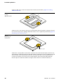
4.3
Mounting of several read/write heads on metal frames or metal carriers............................................. 3
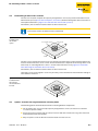
4.4
No mounting of data carriers on metal .................................................................................................. 5
4.5
Upshot – Transmission range interference caused by metal ................................................................. 5
5
EMC guidelines
5.1
Who should use these EMC guidelines? ................................................................................................. 2
5.2
Propagation of an electromagnetic interference .................................................................................. 2
5.3
What can interfere with RFID? ............................................................................................................... 3
5.4
Coupling distances................................................................................................................................. 3
5.5
What does EMC mean? ........................................................................................................................... 4
5.6
Basic rules for safeguarding EMC........................................................................................................... 5
5.6.1
5.6.2
5.6.3
5.6.4
Assembly of a switching cabinet.......................................................................................................................................................... 6
Avoiding sources of interference......................................................................................................................................................... 6
Potential equalization .............................................................................................................................................................................. 6
Shielding of cables .................................................................................................................................................................................... 7
6
BL ident® – Data carriers for the HF-band
6.1
Functionality.......................................................................................................................................... 2
6.1.1
6.1.2
6.1.3
Memory component................................................................................................................................................................................. 2
Data carrier electronics............................................................................................................................................................................ 2
Data carrier antenna ................................................................................................................................................................................. 2
6.2
Overview of data carrier model types.................................................................................................... 3
IV
D101583 1212 - BL ident®
7
BL ident® – Read/write heads for the HF-band
7.1
Functionality.......................................................................................................................................... 2
7.1.1
7.1.2
Read/write head electronics...................................................................................................................................................................2
Read/write head antenna........................................................................................................................................................................2
7.2
Connection of the read/write heads....................................................................................................... 3
7.3
Overview of read/write head model types............................................................................................. 4
7.4
Premoulded cables for connecting interface and read/write heads .................................................... 39
8
Operating data of the read/write heads with corresponding data carriers
8.1
Instructions related to operating data................................................................................................... 2
8.1.1
Distances up to 500 mm ..........................................................................................................................................................................3
8.2
Operating data....................................................................................................................................... 4
9
Accessories
9.1
General description of accessories ........................................................................................................ 2
9.2
Accessories for data carriers with Ø 30 mm and Ø 50 mm...................................................................... 3
9.2.1
9.2.2
Spacer DS-R30 .............................................................................................................................................................................................3
Spacer DS-R50 .............................................................................................................................................................................................3
9.3
Accessories for cylindrical read/write heads, type M18......................................................................... 4
9.3.1
9.3.2
9.3.3
9.3.4
9.3.5
9.3.6
Fixing clamp BS18 ......................................................................................................................................................................................4
Fixing clamp BSN18...................................................................................................................................................................................4
Fixing clamp with stopper BST-18B.....................................................................................................................................................5
Fixing clamp without stopper BST-18N .............................................................................................................................................5
Quick-mount bracket QM-18 ................................................................................................................................................................6
Protective cap SKN/M18 ..........................................................................................................................................................................6
9.4
Accessories for cylindrical read/write heads, type M30......................................................................... 7
9.4.1
9.4.2
9.4.3
9.4.4
Fixing clamp with stopper BST-30B.....................................................................................................................................................7
Fixing clamp without stopper BST-30N .............................................................................................................................................7
Quick-mount bracket QM-30 ................................................................................................................................................................8
Protective cap SKN/M30 ..........................................................................................................................................................................8
9.5
Shared accessories for cylindrical read/write heads of types M18 and M30.......................................... 9
9.5.1
9.5.2
9.5.3
Mounting aid for BST fixing clamps BST-UH.....................................................................................................................................9
Mounting aid for BST fixing clamps BST-UV .....................................................................................................................................9
Name plates for BST fixing clamps BST-BS..................................................................................................................................... 10
9.6
Accessories for rectangular read/write heads of type CK40 ................................................................ 11
9.6.1
9.6.2
9.6.3
9.6.4
9.6.5
Protective bracket MF-CK40-1S.......................................................................................................................................................... 11
Protective bracket MF-CK40-2S.......................................................................................................................................................... 11
Protective bracket MF-CK40-3S.......................................................................................................................................................... 11
Protective housing SG40 ...................................................................................................................................................................... 12
Protective housing SG40/2 .................................................................................................................................................................. 12
D101583 1212 - BL ident®
V
9.6.6
9.6.7
9.6.8
Adjusting rail JS 025/037.......................................................................................................................................................................13
Protective cap T-CK40-T-FC..................................................................................................................................................................14
Protective cap T-CK40-D-FC.................................................................................................................................................................14
9.7
Handheld with accessories................................................................................................................... 15
9.7.1
9.7.2
9.7.3
Handheld-Computer PD-Ident ...........................................................................................................................................................15
Handheld-Computer PS-Ident-WLAN with WLAN functionality ............................................................................................15
Handheld accessories.............................................................................................................................................................................16
10
VI
Glossary
D101583 1212 - BL ident®
Warning!
Before commencing the installation
Switch device off.
Protect device from accidentally switching it on.
Determine whether device is free of voltage.
Grounding and short-circuiting.
Cover or enclose adjacent parts which remain under voltage.
The instructions provided for mounting the device must be followed.
Only personnel qualified per EN 50 110-1/-2 (VDE 0105 Section 100) are permitted to handle and
operate this device/system.
In regards to the installation, please ensure that you follow the statical discharge procedure on your
person prior to touching the device.
The function earth (FS) must be connected to the protective earth (PE) or the potential equalization.
The establishment of this connection is the responsibility of the installer.
Connection and signal cables must be installed in such a way that inductive and capacitive
interspersions may not impact the automation functions.
Automation technology equipment and their operating elements must be installed in such a way
that they are protected from accidental operation.
In order to prevent undefined states in the automation equipment caused by cable and wire
breakage on the signal side, respective safety measures must be implemented on the hardware and
software side when establishing the I/O-connection.
Please ensure the safe isolation of low voltage in connection with a 24-Volt supply. Use only power
supply units which meet the requirements per IEC 60 364-4-41 or rather
HD 384.4.41 S2 (VDE 0100 Section 410).
Fluctuations or rather deviations of the power supply voltage from the nominal value may not
exceed tolerances listed in the technical data otherwise operating failures and dangerous situations
can not be excluded.
Emergency-Off equipment per IEC/EN 60 204-1 must remain in effect in all operating modes of the
automation equipment. Release of the Emergency-Off equipment must not cause a restart.
Built-in devices for enclosures or cabinets must only be operated and maintained when installed;
tabletop devices or portables only when the housing is closed.
Measures must be taken to ensure that an interrupted program can be restarted according to
specifications following voltage drops and failures. Here, no dangerous operating states including
brief ones must occur; if necessary force Emergency-Off.
External measures must be taken at locations where failures of the automation equipment may
cause damage to persons and property; these external measures must ensure or rather force safe
operation even when failures or interferences occur (e.g. with the help of independent limit
switches, mechanical locks, etc.).
The electrical installation must be completed according to relevant specifications (e.g. cable
diameters, fuses, connection of earth conductor).
Only qualified personnel is permitted to complete all work related to transportation, installation,
start-up and maintenance. (Adhere to IEC 60 364 or rather HD 384 or DIN VDE 0100 and national
accident prevention rules).
All covers and doors must be closed during operation.
D101583 1212 - BL ident®
VII
VIII
D101583 1212 - BL ident®
1
About this manual
1.1
Explanation of used symbols ................................................................................................................ 2
1.2
Introduction ........................................................................................................................................... 2
1.3
General instructions............................................................................................................................... 2
1.3.1
1.3.2
Intended use ................................................................................................................................................................................................3
Instructions for project planning/product installation.................................................................................................................3
D101583 1212 - BL ident®
1-1
About this manual
1.1
Explanation of used symbols
Danger
Certain risk of personal injury
Proceed with special caution.
This symbol is shown next to warnings, indicating a potential source of danger.
This refers to personal injury or death that are almost certain if warning instructions are not
observed.
Attention
Risk of damage to devices
Proceed with special care.
This symbol is shown next to warnings, indicating a potential source of danger.
This refers to possible damage to systems (hardware and software) and installations.
Note
Important information and description of a particular procedure
This symbol is placed next to general instructions that indicate important information on the
procedure for one or several operations. The relevant instructions may simplify the work and
help for example to avoid additional work caused by incorrect actions.
1.2
Introduction
This manual contains all information for the professional installation of the BL ident®-system, especially
in regards to data carriers and read/write heads.
The following chapters provide an overview of the BL ident®-system, how to plan a BL ident®-system,
show the required installation guidelines and provide a short overview of the EMC guidelines.
In addition, the manual describes functional principles of the data carriers and the read/write heads,
technical data, and operating data, as well as available accessories.
1.3
General instructions
Attention
Please read this section carefully. Safety aspects cannot be left to chance when handling
electrical devices.
This manual contains the required information for the start-up of the TURCK BL ident®-system.
It was specifically developed for qualified professional personnel with the required technical knowhow.
1-2
D101583 1212 - BL ident®
General instructions
1.3.1
Intended use
Danger
The devices described in this manual must be used only in applications outlined in this
manual and the respective technical descriptions, and only in connection with devices and
components from certified third-party manufacturers.
The prerequisites for perfect and save operation of the devices are proper transportation, storage,
assembly and installation, as well as careful operation and maintenance.
1.3.2
Instructions for project planning/product installation
Danger
It is imperative that the safety and accident protection guidelines are heeded in regards to
each application.
The prerequisites for perfect and save operation of the devices are proper transportation, storage,
assembly and installation, as well as careful operation and maintenance.
Danger
It is imperative that the safety and accident protection guidelines are heeded in regards to
each application.
D101583 1212 - BL ident®
1-3
About this manual
1-4
D101583 1212 - BL ident®
2
The TURCK-BL ident®-system
2.1
BL ident® – Modular RFID-System........................................................................................................... 2
2.1.1
2.1.2
2.1.3
2.1.4
BL ident®– Flexibility for your application; security for your investment! ..............................................................................2
BL ident® – Data carriers............................................................................................................................................................................2
BL ident® – Read/write heads..................................................................................................................................................................2
BL ident® – Interfaces .................................................................................................................................................................................3
– Interfaces for the fieldbus connection: Sets and single components ................................................................................4
– Compact fieldbus stations with interfaces for fieldbus connection ...................................................................................8
2.2
Schematic display of the identification system BL ident® .................................................................... 11
2.2.1
2.2.2
Support for BL ident®-projects............................................................................................................................................................. 12
Networking with BL ident®-systems.................................................................................................................................................. 12
2.3
Identification systems with radio frequency technology (RFID).......................................................... 13
2.4
Performance characteristics and applications of the BL ident® system................................................ 13
2.4.1
2.4.2
2.4.3
2.4.4
2.4.5
Protection class ........................................................................................................................................................................................ 13
Life-cycle..................................................................................................................................................................................................... 14
Transmission frequency ........................................................................................................................................................................ 14
Model types............................................................................................................................................................................................... 14
– Data carriers ......................................................................................................................................................................................... 14
– Read/write heads ............................................................................................................................................................................... 14
Memory capacity ..................................................................................................................................................................................... 15
2.5
User data ranges of the data carrier versions ...................................................................................... 16
2.5.1
2.5.2
Overview of the HF-TURCK data carriers ........................................................................................................................................ 16
Overview of the UHF-TURCK data carriers ..................................................................................................................................... 19
2.6
Read/write time in the data collection range of the HF read/write head ............................................. 20
2.6.1
2.6.2
2.6.3
EEPROM-I-Code-SL2 data carriers ..................................................................................................................................................... 21
EEPROM-I-Code-SL1 data carriers ..................................................................................................................................................... 23
FRAM data carrier .................................................................................................................................................................................... 25
2.7
Data carrier speed to the read/write head for HF-RFID-systems ......................................................... 27
2.7.1
2.7.2
2.7.3
Read/write distances.............................................................................................................................................................................. 28
BL ident® simulator for HF-RFID .......................................................................................................................................................... 28
BL ident®-simulator for UHF-RFID (Ray-Tracer).............................................................................................................................. 30
2.8
Compatibility ....................................................................................................................................... 31
2.9
Application examples: ......................................................................................................................... 32
D101583 1212 - BL ident®
2-1
The TURCK-BL ident®-system
2.1
BL ident® – Modular RFID system
BL ident® is a complete RFID-system which showcases its special characteristics, especially in the
industrial environment. The system's modular design is based on the I/O-systems BL67 (field
installation) and BL20 (switching cabinet installation) or rather on the compact fieldbus modules
BL compact (field mount).
Each BL ident®-system can be assembled as a custom RFID solution by freely combining data carriers,
read/write heads, connectivity technology, and interfaces (gateway and RFID-module).
Available are not only extremely fast FRAM data carriers with almost unlimited write capacity but also
high temperature versions up to 240 °C which are suitable for a paint finishing line application.
Another feature: BL ident® can be integrated very easily into existing system configurations.
2.1.1
BL ident®– Flexibility for your application; security for your investment!
The RFID-system BL ident® provides on all levels the flexibility you need for your application:
From the selection of the data carriers to the read/write heads, including connection to the control
level. You will always have the opportunity to perfectly configure the system in order to meet your
specific application needs.
BL ident® is save for the future and interoperable because it is based on international, worldwide
standards. Thus you will enjoy a high level of investment security.
2.1.2
BL ident® – Data carriers
Special, small design (Ø 7.5 mm for HF)
EEPROM data carrier for high piece numbers
FRAM data carrier for high speeds and a high number of write cylces
High temperature carrier for continuous process control at -40…+240 °C
Autoclave data carrier for an application with approx. 130 °C hot steam under pressure
Direct mounting on metal
Open and worldwide standards (ISO 15693 and ISO 18000-6C)
2.1.3
BL ident® – Read/write heads
Industry-suitable and robust design
Fully casted read/write heads (HF)
Read/write distances of up to 1000 mm, depending on environmental conditions (HF) or several
meters (UHF)
Suitable for food and beverage applications, wash-down (IP69K)
2-2
D101583 1212 - BL ident®
BL ident® – Modular RFID system
2.1.4
BL ident® – Interfaces
Modular design (BL20 and BL67) with up to 16 channels per gateway depending inter alia on the
kind of fieldbus, system parameter and performance of the periphery
BL ident® for switching cabinet installation
BL67 for direct field installation
BL compact for direct field installation (in part with integrated I/Os)
Cable length to read/write head up to 50 m
Possible alternating operation of HF and UHF read/write heads on the same interface modules
Versatile and user-friendly fieldbus connections (PROFIBUS-DP, DeviceNet™, CANopen,
PROFINET IO, Ethernet Modbus TCP, EtherNet/IP™, EtherCAT)
Programmable gateways for decentralized and autarkic control tasks
Additional integration of I/O-modules on the same gateway or rather bus node
Modules for space-saving and user-friendly mounting in the field (BL compact)
D101583 1212 - BL ident®
2-3
The TURCK-BL ident®-system
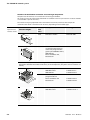
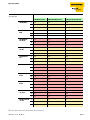
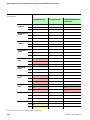
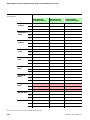
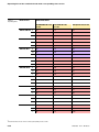
Interfaces for the fieldbus connection: Sets and single components
Complete sets of interfaces are available for connecting the fieldbus.
An existing set may be retroactively fitted with an additional channel (an electronic and basic module
are needed for a pair of channels).
The interfaces may be populated with a maximum of 8 channels; interfaces with simple I/Ocommunication allow a maximum of 16 channels, depending on the fieldbus type.
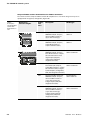
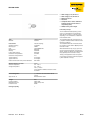
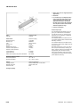
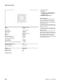
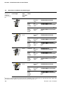
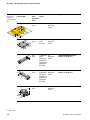
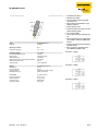
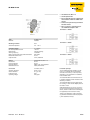
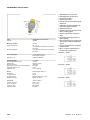
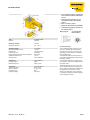
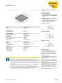
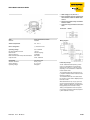
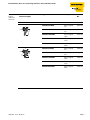
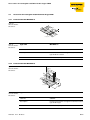
Table 1:
Expansion and
interfaces in IP20
Dimensions/
enclosure lengths
Protection
class
Description
Model type
IP20
BL20 basic module
BL20-S4T-SBBS
IP20
RFID electronic module for
use with function blocks or
rather with programmable
gateway for PROFIBUS-DPV1,
PROFINET IO,
Ethernet Modbus TCP,
EtherNet/IP™
BL20-2RFID-A
128,9
12,6
LED
74,1
55,4
12,6
Interfaces in 2-, 4-, 6- and 8-channel designs are available (the last digit of the model type
description identifies the number of channels; in the example here, only the 2-channel versions are
shown).
128,9
IP20
74,1
LED
IP20
74,4
72,5 85,1 97,7 110,3
IP20
129,5
74,1
Interfaces (sets) for
PROFIBUS-DPV1
PROFINET IO
TI-BL20-DPV1-2
TI-BL20-EN-PN-2
Interfaces (sets) –
programmable for
Ethernet Modbus TCP
EtherNet/IP™
TI-BL20-PG-EN-2
TI-BL20-PG-EIP-2
Interfaces (sets) ECONOMY for
PROFIBUS-DPV1
TI-BL20-E-DPV1-2
LED
75
55,4 68 80,6 93,2
2-4
D101583 1212 - BL ident®
BL ident® – Modular RFID system
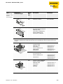
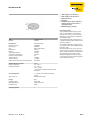
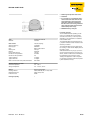
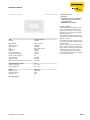
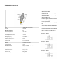
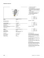
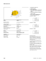
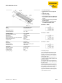
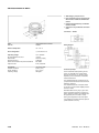
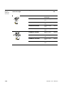
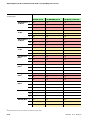
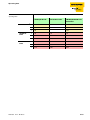
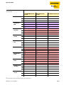
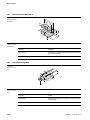
Table 2:
Expansion and
interfaces in IP20
for basic
communication
Dimensions/
enclosure lengths
Protection
class
Description
Model type
IP20
BL20 basic module
BL20-S4T-SBBS
IP20
RFID electronic module for
basic I/O-communication for
PROFIBUS-DPV1,
DeviceNet™, PROFINET IO,
Ethernet Modbus TCP,
EtherNet/IP™, CANopen
BL20-2RFID-S
128,9
12,6
LED
74,1
55,4
12,6
Interfaces in 2-, 4-, 6- and 8-channel designs are available (the last digit of the model type
description identifies the number of channels; in the example here, only 2-channel versions are
shown).
128,9
IP20
74,1
LED
74,4
Interfaces (sets) for basic
communication
PROFIBUS-DPV1
DeviceNet™
Ethernet Modbus TCP
PROFINET IO
EtherNet/IP™
TI-BL20-DPV1-S-2
TI-BL20-DN-S-2
TI-BL20-EN-S-2
TI-BL20-EN-PN-S-2
TI-BL20-EIP-S-2
72,5 85,1 97,7 110,3
IP20
Interfaces (sets) –
programmable for
Ethernet Modbus TCP
EtherNet/IP™
IP20
129,5
74,1
LED
75
Interfaces (Sets) ECONOMY
for basic communication
PROFIBUS-DPV1
DeviceNet™
CANopen
EtherCAT
TI-BL20-PG-EN-S-2
TI-BL20-PG-EN-2
TI-BL20-PG-EIP-S-2
TI-BL20-PG-EIP-2
TI-BL20-E-DPV1-S-2
TI-BL20-E-DN-S-2
TI-BL20-E-CO-S-2
TI-BL20-E-EC-S-2
55,4 68 80,6 93,2
D101583 1212 - BL ident®
2-5
The TURCK-BL ident®-system
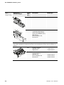
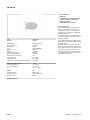
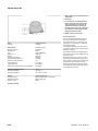
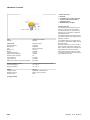
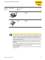
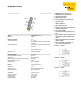
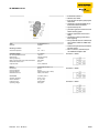
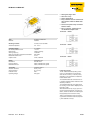
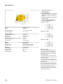
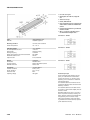
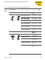
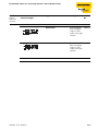
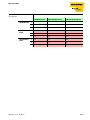
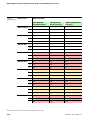
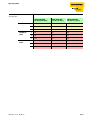
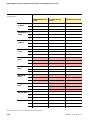
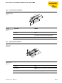
Table 3:
Expansion and
interfaces in IP67
Dimensions/
enclosure lengths
LED
32
Protection
class
Description
Model type
IP67
BL67 basic module
BL67-B-2M12
IP67
RFID electronic module for
use with function blocks or
rather with programmable
gateway for PROFIBUS-DPV1,
PROFINET IO,
Ethernet Modbus TCP,
EtherNet/IP™
BL67-2RFID-A
91
77,5
13
145
Interfaces in 2-, 4-, 6- and 8-channel designs are available (the last digit of the model type
description identifies the number of channels; in the example here, only 2-channel versions are
shown).
IP67
LED
32
13
Interfaces (sets) for
PROFIBUS-DPV1
PROFINET IO
TI-BL67-DPV1-2
TI-BL67-EN-PN-2
Interfaces (sets) –
programmable for
PROFIBUS-DP
Ethernet Modbus TCP
EtherNet/IP™
TI-BL67-PG-DP-2
TI-BL67-PG-EN-2
TI-BL67-PG-EIP-2
77,5
IP67
145
2-6
108 140 172 204
D101583 1212 - BL ident®
BL ident® – Modular RFID system
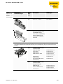
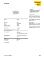
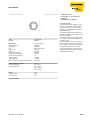
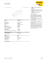
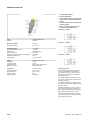
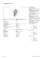
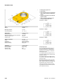
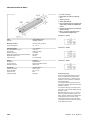
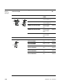
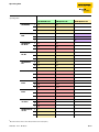
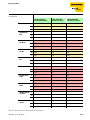
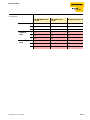
Table 4:
Expansion and
interfaces in IP67
for basic
communication
Dimensions/
enclosure lengths
LED
32
Protection
class
Description
Model type
IP67
BL67 basic module
BL67-B-2M12
IP67
RFID electronic module for
basic I/O-communication
for PROFIBUS-DPV1,
DeviceNet™, PROFINET IO,
Ethernet Modbus TCP,
EtherNet/IP™, CANopen,
EtherCAT
BL67-2RFID-S
91
77,5
13
145
Interfaces in 2-, 4-, 6- and 8-channel designs are available (the last digit of the model type
description identifies the number of channels; in the example here, only 2-channel versions are
shown).
IP67
LED
32
13
77,5
145
Interfaces (sets) for basic
communication
PROFIBUS-DPV1
DeviceNet™
PROFINET IO
PROFINET IO + AIDA
108 140 172 204
EtherNet/IP™
Multi protocol
(Ethernet Modbus TCP +
EtherNet/IP™)
IP67
Interfaces (sets) for basic
communication,
programmable for
PROFIBUS-DP
Ethernet Modbus TCP
EtherNet/IP™
D101583 1212 - BL ident®
TI-BL67-DPV1-S-2
TI-BL67-DN-S-2
TI-BL67-EN-PN-S-2
TI-BL67-PN-AC-2
TI-BL67-PN-AC-S-x
TI-BL67-EIP-S-2
TI-BL67-EN-S-2
TI-BL67-PG-DP-S-2
TI-BL67-PG-EN-S-2
TI-BL67-PG-EN-2
TI-BL67-PG-EIP-S-2
2-7
The TURCK-BL ident®-system
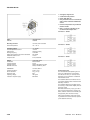
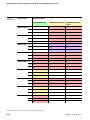
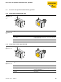
Compact fieldbus stations with interfaces for fieldbus connection
The interfaces of the compact fieldbus stations BL compact have a 2-channel design and in part are
equipped with integrated, configurable, digital I/Os.
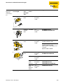
Table 5:
BL compact –
Compact fieldbus
stations with
RFID interface in
IP67
Dimensions/
enclosure lengths
Protection
class
Description
Model type
IP67
Compact fieldbus station for
PROFIBUS-DP (BL compact,
advanced RFID interface =
azyclic data exchange)
BLCDP-2M12MT2RFID-A
IP67
Compact fieldbus station for
PROFIBUS-DP (BL compact,
simple RFID interface =
simple communication)
BLCDP-2M12MT2RFID-S
IP67
Compact fieldbus station for
PROFIBUS-DP (BL compact,
basic RFID interface = simple
I/O-communication and 8
digital inputs (outputs,
configurable, PNP with
diagnostic function)
BLCDP-6M12LT2RFID-S-8XSG-PD
IP67
Compact fieldbus station for
DeviceNet™ (BL compact,
simple RFID Interface = simple
I/O communication) 8 digital
inputs/outputs, configurable,
PNP, with diagnostic function)
BLCDN-6M12LT2RFID-S-8XSG-PD
IP67
Compact fieldbus station for
PROFIBUS-DP (BL compact,
advanced RFID interface =
acyclic data exchange)
8 digital inputs, PNP, with
diagnostic function)
BLCDP-6M12LT2RFID-A-8DI-PD
IP67
Compact fieldbus station for
PROFIBUS-DP (BL compact,
advanced RFID interface =
acyclic data exchange)
8 digital inputs/outputs,
configurable, PNP, with
diagnostic function)
BLCDP-6M12LT2RFID-A-8XSG-PD
44,5
32,5
71
102 ±1
113
44,5
32,5
71
157 ±1
168
2-8
D101583 1212 - BL ident®
BL ident® – Modular RFID system
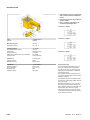
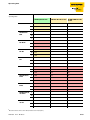
Table 5:
BL compact –
Compact fieldbus
stations with
RFID interface in
IP67
Dimensions/
enclosure lengths
Protection
class
Description
Model type
IP67
Compact fieldbus station for
PROFIBUS-DP (BL compact,
simple RFID interface = simple
I/O communication) 8 digital
inputs, PNP, with diagnostic
function)
BLCDP-6M12LT2RFID-S-8DI-PD
IP67
Compact fieldbus station for
DeviceNet™ (BL compact,(
simple RFID interface = simple
I/O communication)
8 digital inputs/outputs,
configurable, PNP, with
diagnostic function)
BLCDN-6M12LT2RFID-S-8XSG-PD
IP67
Compact fieldbus station for
CANopen (BL compact, simple
RFID interface = simple I/O
communication) 8 digital
inputs/outputs, configurable,
PNP, with diagnostic function)
BLCCO-6M12LT2RFID-S-8XSG-PD
IP67
Compact fieldbus station for
CANopen (BL compact, simple
RFID interface = simple I/O
communication)
BLCCO-4M12L-2RFIDS-2RFID-S
IP67
Compact fieldbus station for
Multi protocol = Ethernet
Modbus TCP + EtherNet/IP™
(BL compact,simple RFID
interface =
simple I/O-communication)
BLCEN-2M12LT2RFID-S
IP67
Compact fieldbus station for
Multi protocol = Ethernet
Modbus TCP + EtherNet/IP™
(BL compact, simple RFID
interface = simple I/Ocommunication), 8 digital
inputs/outputs, configurable,
PNP, with diagnostic function)
BLCEN-6M12LT2RFID-S-8XSG-PD
IP67
Compact fieldbus station for
Multi protocol = Ethernet
Modbus TCP + EtherNet/IP™
(BL compact,simple RFID
interface = simple I/Ocommunication), RS232 serial
interface
BLCEN-3M12LT1RS232-2RFID-S
44,5
32,5
71
157 ±1
168
D101583 1212 - BL ident®
BLCEN-4M12LT2RFID-S-2RFID-S
2-9
The TURCK-BL ident®-system
Table 5:
BL compact –
Compact fieldbus
stations with
RFID interface in
IP67
Dimensions/
enclosure lengths
Protection
class
Description
Model type
IP67
Compact fieldbus station for
DeviceNet™ (BL compact,
simple RFID interface =
simple I/O-communication)
BLCDN-2M12S2RFID-S
IP67
Compact fieldbus station for
CANopen (BL compact, simple
RFID interface = simple I/O
communication)
BLCCO-2M12S2RFID-S
44,5
32,5
71
82 ±1
93
2-10
D101583 1212 - BL ident®
Schematic display of the identification system BL ident®
2.2
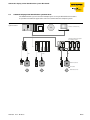
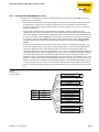
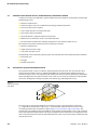
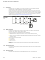
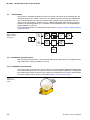
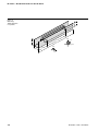
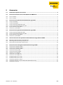
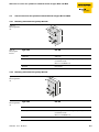
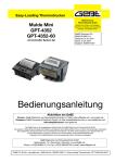
Schematic display of the identification system BL ident®
The TURCK BL ident®-system consists of multiple layers. Each layer offers different variations.
It is possible to retrofit the application so that it accommodates the complete system.
Figure 1:
System overview
PLC/PC for commissioning
Interface module for integration
in the fieldbus systems
D
IP67
IP20
IP67
Read/write devices
Air Interface
Mobile data carriers
D101583 1212 - BL ident®
2-11
The TURCK-BL ident®-system
2.2.1
Support for BL ident®-projects
The following software and documents will provide additional help for project planning, installation,
and start-up:
To simulate and optimize an application, please go to http://www.turck.com. where you may access
the "BL ident®-Simulator" for free.
D101581 - "Interface Module for Fieldbus Connection." This manual describes the professional
operation of BL ident®-interface modules.
D101579 - "Start-up with PROFIBUS-DP"
D101640 - "Start-up with CoDeSys for Programmable Gateways"
D101642 - "Start-up with DeviceNetTM"
D101644 - "Start-up with EtherNet/IPTM"
D101648 - "Start-up with PROFINET"
D101763 - "Start-up with CANopen"
D101831 - "Installation of the BL ident®UHF-System"
D101606 - This manual contains a software description of a so-called "Handheld" (programming
device) which is used to read and write data independent of the location.
D101584 - This manual contains a hardware description of a so-called "Handheld" (programming
device) which is used to read and write data independent of the location.
The listed manuals can be downloaded from the internet.
2.2.2
Networking with BL ident®-systems
Based on the possibility to integrate BL ident®-systems into (existing) bus systems, a network of multiple
BL ident®-systems can be established.
Please follow the guidelines for maximum expansion concerning the bus system in use.
For example, without repeater a PROFIBUS-DP-system can comprise a maximum of 31 stations and a
master.
2-12
D101583 1212 - BL ident®
Identification systems with radio frequency technology (RFID)
2.3
Identification systems with radio frequency technology (RFID)
RFID is the abbreviation for radio frequency identification.
A RFID-system comprises a data carrier, a device to read from and write to a data carrier, as well as other
devices which are used to transfer and process data.
The transmission of data from the data carrier to the read/write head occurs free of contact via
electromagnetic waves. This type of transmission is insensitive to mechanical contamination by dirt or
temperature fluctuations.
The data carriers may be directly affixed to an object. This is why the term "mobile data carrier" is used
as well. Other terms for the data carrier are TAG or transponder. The data content may consist of
production and manufacturing data. Important here are those data which identify the product. Thus
the description "identification system".
Additional opportunities exist because the data content can be changed by writing to the data carrier.
Thus production/manufacturing processes can be retraced. Logistics/distribution can be optimized.
The "identification systems" can be integrated into (existing) fieldbus automation systems
(e. g. PROFIBUS-DP). Connection to the respective fieldbus system occurrs via a suitable interface
module.
Standardized software components (e.g. the Proxy Ident Function Block for PROFIBUS-DP) allows userfriendly system integration and start-up.
2.4
Performance characteristics and applications of the BL ident® system
In order to meet the demands of different application environments, the TURCK BL ident® system offers
numerous combinations from data carriers to read/write heads, as well as interface modules and
automation systems (e.g. PROFIBUS-DP). Software components allow user-friendly integration and
start-up.
The following describes the performance characteristics of the TURCK BL ident®-System:
2.4.1
Protection class
Some data carriers, including the respective read/write heads have a high protection class (e.g. IP69K)
and thus are suitable for use in the harshest, industrial environments.
The read/write heads are also available in IP69K (wash-down design).
Connection to a fieldbus system is realized with a suitable TURCK interface module. The interface
modules for CANopen are available in protection class IP20. TURCK connection cables with the
respective protection class complete the identification system.
Temperature-resistant data carriers up to 240°C are available for the high temperature range.
D101583 1212 - BL ident®
2-13
The TURCK-BL ident®-system
2.4.2
Life-cycle
The life-cycle is a result of the data carriers' possible read/write operations.
FRAM data carriers can guarantee a unlimited number of read operations and 1010 write operations.
EEPROM data carriers can guarantee a unlimited number of read operations and 104 or 105 write
operations.
The data carriers do not require a battery.
2.4.3
Transmission frequency
The TURCK BL ident® system operates with a transmission frequency of 13.56 MHz in the HF range or
with a country-specific transmission frequency in the UHF range (860-960 MHz) between the data
carriers and the read/write heads.
HF: Systems which operate with this transmission frequency are mostly insensitive to electromagnetic
interference. This is why the transmission frequency of 13.56 MHz is now standard for many RFID
applications.
UHF: Systems with this frequency range reach longer read/write distances compared to HF, typically
several meters. The carrier frequencies are country specific; in Europe they are between 865 and
868 MHz, for example.
2.4.4
Model types
Data carriers
HF: TURCK offers round, flat data carriers, e.g. with 16, 20, 30 and 50 mm diamters, for the HF operating
frequency.
The high temperature data carriers have a cylinder design (e.g. 22 x 125 mm).
Inlays and stickers have foil thickness (e.g. size 49 x 46 mm).
Special designs are suitable for mounting on metal. Other data carrier designs have glas cylinder
housing, or flat check card format. Some data carriers have holes so that they can be affixed with screws.
UHF: UHF-suitable data carriers have different designs and can be mounted in various ways; they are
either optimized for small housing dimensions or long data transmission distances. Data carriers with
high protection class, also for external applications, are available, including data carriers for direct
mounting on metal or printable labels.
TURCK delivers customer-specific data carrier solutions upon request.
Read/write heads
HF: The read/write heads are available in different designs from standard M18 and M30 thread to
cuboid designs Q14, CK40, Q80, S32XL, including Q80L400 and Q350 for long distances of up to
1000 mm.
UHF: Different cuboid designs are available, e.g. compact read/write heads in a housing with approx.
170 mm or 280 mm edge length for long data transmission distances of up to several meters.
2-14
D101583 1212 - BL ident®
Performance characteristics and applications of the BL ident® system
2.4.5
Memory capacity
The memory capacity of the data carriers for the HF range is 64 or 128 byte (48 or 112 Byte user data)
with an EEPROM-memory and 2 or 8 Kbyte (2000 or 7936 byte user data) with a FRAM-memory.
EEPROM data carriers with up to 110 byte (94 byte user data) are available for the UHF range.
FRAM: (Ferroelectric Random Access Memory), non-volatile, longer life-cycle because of a larger
number of read/write operations and faster write operations compared to EEPROM.
EEPROM: (Electrically Eraseable Programmable Read Only Memory), non-volatile.
The data carriers for HF operating frequency meet the ISO 15693 communication standard.
The data carriers for the UHF frequency range meet the ISO 18000-6C and EPCglobal Class 1 Gen 2
communication standard.
D101583 1212 - BL ident®
2-15
The TURCK-BL ident®-system
2.5
User data ranges of the data carrier versions
2.5.1
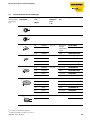
Overview of the HF-TURCK data carriers
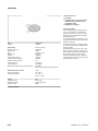
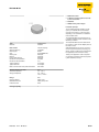
The HF data carriers type I-Code SL2 are writable and readable, starting with byte No. 0 to Byte No. 111.
Table „Data structure of the I-Code SL2 data carriers” page 2-16 describes the data structure of the data
carriers:
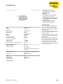
TW-I14-B128
TW-L43-43-F-B128
TW-L82-49-P-B128
TW-R16-B128
TW-R20-B128
TW-R30-B128
TW-R50-B128
TW-R50-90-HT-B128
...
Table 6:
Data structure of
the I-Code SL2
data carriers
2-16
Byte No.
(StartAddress)
Content
Access
Block No.
-16 to -9
UID
Read only
-4 to -3
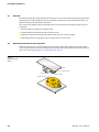
-8 to -5
Tag information
-2
-4 to -1
Conditions for write
access
Read only via special
commands
0 to 111
User data range
Read/write
0 to 27
(one block
comprises
4 Byte)
-1
D101583 1212 - BL ident®
User data ranges of the data carrier versions
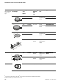
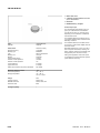
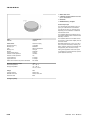
The HF data carriers type I-Code SL1 are readable and writable, starting with byte No. 19 to Byte No. 64.
Table „Data structure of the I-Code SL1 data carriers” page 2-17 describes the data structure of the data
carriers:
TW-R16-B64
TW-R22-HT-B64
...
Table 7:
Data structure of
the I-Code SL1
data carriers
Byte No.
(StartAddress)
Content
0 to 8
UID
Read only
0 to 1
9 to 12
Conditions for write
access
Read only via special
command
2
13 to 16
Special functions (e.g.
EAS / QUIET)
Read/write via special
commands
3/4
17
Family code
18
Application identifier
19 to 64
User data range
Read/write
4/5 to 15
D101583 1212 - BL ident®
Access
Block No.
(one block
comprises
4 Byte)
2-17
The TURCK-BL ident®-system
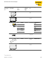
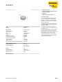
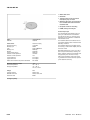
The HF data carriers type FRAM are readable and writable, starting with byte No. 0 to Byte No. 1999.
Table „Data structure of the FRAM data carriers” page 2-18 describes the data structure of the data
carriers:
TW-R20-K2
TW-R30-K2
TW-R50-K2
TW-R50-90-HT-K2
...
Table 8:
Data structure of
the FRAM data
carriers
Byte No.
(StartAddress)
Content
Access
Block No.
0 to 1999
User data range
Read/write
0 to 249
2000 to 2007
UID
Read only via
250
2008 to 2015
AFI, DSFID, EAS
Read/write (with
limitations) via special
command
251
2016 to 2047
Special functions (e.g.
EAS / QUIET)
Read only via special
command
252 to 255
(one block
comprises
8 Byte)
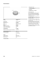
The HF data carriers type FRAM are readable and writable, starting with byte No. 0 to Byte No. 7935.
TW-R50-K8
The data carrier applies of 248 blocks (00Hex up to F7Hex) with 32 Bytes each.
2-18
D101583 1212 - BL ident®
User data ranges of the data carrier versions
2.5.2
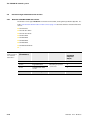
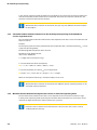
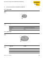
Overview of the UHF-TURCK data carriers
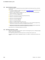
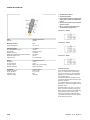
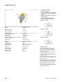
The UHF data carrier memory hierarchy is divided into four logical banks per ISO 18000-6C and can
accommodate several blocks.
Reserved area: Among other things (depending on the type of data carrier) this bank contains the
passwords for memory access and memory deactivation. The passwords for the deactivation
function are stored in the memory addresses 00hex to 1Fhex. Memory access occurs via separate
protocol commands.
EPC (Electronic Product Code) or UII (Unique Item Identifier): This bank contains the basic
identification data of the transponder. Thus a clear identification is later possible during operation
if the data is different. In the first data word (2 Bytes) there are the specific protocol control bytes for
the data carrier (from address 0x0000 on). The second word contains the 16 bit check sum (CRC) in
the memory addresses from 0x0002 on. The data range of the EPC begins with address 0x0004.
The data carriers vary on the basis of the first 8 bytes of the data range (addresses 0x0004 up to
0x000C.
TID (Data Carrier Identification): This bank contains one of three class-identifier values (E0hex, E2hex
or E3hex) per ISO/IEC 15963 in the memory addresses 00hex to 07hex. The class-identifier does not
specify the application. If the class-identifier is E0hex, TID contains a 48 bit serial number, the
composite 64 bit data carrier ID is unique among all data carrier classes defined in ISO/IEC 15963 and
locked by manufacturer. If the class-identifier is E2hex, TID contains a 12 bit mask-designer identifier
a vendor-defined 12 bit data carrier model number, and the usage from addresses above 1Fhex is
defined in version 1.5 and above of the EPCglobal data standards. If the class identifier is E3hex, TID
contains an 8 bit manufacturer identifier followed by 2 byte user memory present and size data, the
48 bit serial number, the 1 bit XTID and 15 bit XTID header data. The composite 80 bit data carrier ID
is unique among all classes of data carriers defined in ISO/IEC 15963 and locked by manufacturer.
User area: This bank is optional and contains a memory with various capacity for open, user-specific
use.
Figure 2:
UHF data carrier
memory hierarchy
MSB
00hex
MSB
10hex
00hex
MSB
Bank 11
User
Bank 10
TID
Bank 01
EPC/UII/...
Bank 00
Reserved
220hex
210hex
20hex
10hex
00hex
MSB
30hex
20hex
10hex
00hex
D101583 1212 - BL ident®
..
.
Word 0 of Block 0
..
.
TID [15:0]
TID [31:16]
..
.
Optional XPC_W2 [15:0]
Optional XPC_W2 [15:0]
..
.
EPC/UII/... [15:0]
..
.
EPC/UII/... [N:N-15]
PC [15:0]
CRC [15:0]
..
.
Access Passwd [15:0]
Access Passwd [31:16]
Kill Passwd [15:0]
Kill Passwd [31:16]
LSB
0Fhex
LSB
1Fhex
0Fhex
LSB
22Fhex
21Fhex
2Fhex
1Fhex
0Fhex
LSB
3Fhex
2Fhex
1Fhex
0Fhex
2-19
The TURCK-BL ident®-system
2.6
Read/write time in the data collection range of the HF read/write head
The time that the data carrier must remain in the data collection range of the read/write head in order
to savely read and write all needed data depends on the following factors:
Command type (read or write)
Data carrier with memory type EEPROM or FRAM
Data volume
Expansion of the data detection range (depends on the combination of the type of read/write head
and the data carrier
Note
Please observe the recommended distances between the data carrier and the read/write
head.
You may find the specifications for "recommended" and "maxium distance" in the chapter
"Operating Data."
Data detection may be interrupted by the following interferences:
Electromagnetic interferences
Strong reflexions on metal parts in the direct environment of the data detection range
The following sections show the required time for the read/write functions of a specific data volume.
The required time depends on the memory type of the data carrier.
Currently BL ident® offers HF data carriers with the following memory types:
EEPROM-I-Code SL1
EEPROM-I-Code SL2
FRAM
Currently BL ident® offers UHF data carriers with the following memory types:
EEPROM-U-Code G2
EEPROM-Monza
EEPROM-Higgs
2-20
D101583 1212 - BL ident®
Read/write time in the data collection range of the HF read/write head
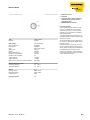
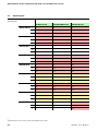
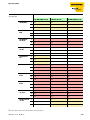
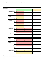
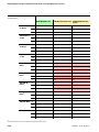
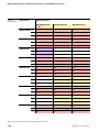
EEPROM-I-Code-SL2 data carriers
The EEPROM data carrier is divided into data blocks. Each data block comprises:
4 byte
The start address and length of the byte to be read from and written to can be freely selected within the
user data range („Data structure of the I-Code SL2 data carriers” page 2-16).
For examining the required read/write times it should be observed that access to the user data range
always occurs block by block. For example, time is not shortened when the length of the byte to be read
is less than 4 byte. The start addresses of the blocks are 0,4,8,12...
Two blocks are processed when the selected start address is "5" and the length of the byte to be read is
"4".
For time-critical applications, please observe the two instructions below:
Note
As start address and length of the byte to be read, please only enter multiple of "4"!
The start address and length of the byte to be read are attributes of the read/write
commands!
Note
Please select small addresses when selecting the data memory range!
Attention
The following two diagrams are valid when the instructions for time-critical applications are
followed!
D101583 1212 - BL ident®
2-21
The TURCK-BL ident®-system
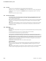
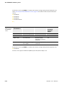
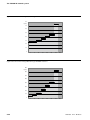
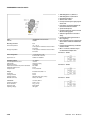
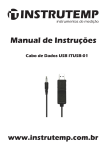
Figure 3: Pause times when reading a data carrier type "EEPROM-I-Code-SL2“.
80
t [ms]
75,8
70
60
50
47,0
40
41,6
36,6
30
27,2
28,6
4
8
31,3
20
10
0
16
32
48
64
112
128
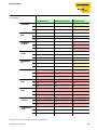
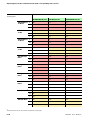
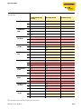
Figure 4: Pause times when writing a data carrier type "EEPROM-I-Code-SL2“.
400
t [ms]
372,6
350
300
250
220,6
200
171,6
150
119,6
100
70,2
50
34,3
0
2-22
4
46,0
8
16
32
48
64
112
128
D101583 1212 - BL ident®
Read/write time in the data collection range of the HF read/write head
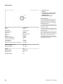
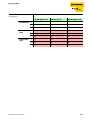
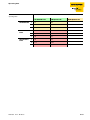
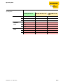
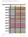
EEPROM-I-Code-SL1 data carriers
The EEPROM data carrier is divided into data blocks. Each data block comprises:
4 byte
The start address and length of the Byte to be read from and written to can be freely selected within the
user data range („Data structure of the I-Code SL1 data carriers” page 2-17.)
For examining the required read/write times it should be observed that access to the user data range
always occurs block by block. For example, time is not shortened when the length of the byte to be read
is less than 4 byte. The start addresses of the blocks are 16, 20, 24, 28...
Two blocks are processed when the selected start address is "19" and the length of the byte to be read
is "4".
For time-critical applications, please observe the two instructions below:
Note
As start address and length of the byte to be read from and written to, please enter multiple
of "4" only!
The start address and length of the byte to be read from and written to are attributes of the
read/write commands!
Note
Please select small addresses when selecting the data memory range!
Attention
The following two diagrams are valid when the instructions for time-critical applications are
followed!
D101583 1212 - BL ident®
2-23
The TURCK-BL ident®-system
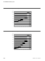
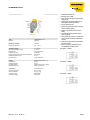
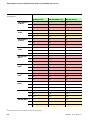
Figure 5: Pause times when reading from a data carrier type "EEPROM-I-Code-SL1“.
80
t [ms]
75,8
70
60
50
47,0
40
41,6
36,6
30
27,2
28,6
4
8
31,3
20
10
0
16
32
48
64
112
128
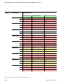
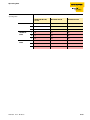
Figure 6: Pause times when writing to a data carrier type "EEPROM-I-Code-SL1“.
400
t [ms]
372,6
350
300
250
220,6
200
171,6
150
119,6
100
70,2
50
34,3
0
2-24
4
46,0
8
16
32
48
64
112
128
D101583 1212 - BL ident®
Read/write time in the data collection range of the HF read/write head
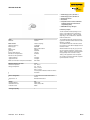
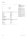
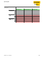
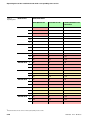
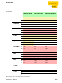
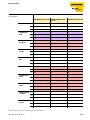
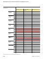
FRAM data carrier
The FRAM data carrier is divided into data blocks. Each data block comprises:
8 byte
The start address and length of the Byte to be read from and written to can be freely selected within the
user data range („Data structure of the FRAM data carriers” page 2-18)
For examining the required read/write times it should be observed that access to the user data range
always occurs block by block. For example, time is not shortened when the length of the byte to be read
is less than 8 byte. The start addresses of the blocks are 8, 16, 24, 32...
Two blocks are processed when the selected start address is "19" and the length of the byte to be read
is "8".
For time-critical applications, please observe the two instructions below:
Note
As start address and length of the byte to be read from and written to, please enter multiple
of "8" only!
The start address and length of the byte to be read from and written to are attributes of the
read/write commands!
Note
Please select small addresses when selecting the data memory range!
Attention
The following two diagrams are valid when the instructions for time-critical applications are
followed!
D101583 1212 - BL ident®
2-25
The TURCK-BL ident®-system
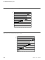
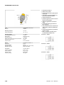
Figure 7: Pause times when reading from the data carrier type "FRAM“.
90
t [ms]
80
81,4
75,6
70
60
50
40
30
45,6
42,0
36,7
28,8
28,8
4
8
31,5
20
10
0
16
32
48
64
112
128
Figure 8: Pause times when writing from the data carrier type "FRAM“.
140
t [ms]
120
116,6
104,6
100
80
67,8
60
56,2
44,8
40
29,7
20
0
2-26
4
8
33,7
16
32
48
64
112
128
D101583 1212 - BL ident®
Data carrier speed to the read/write head for HF-RFID-systems
2.7
Data carrier speed to the read/write head for HF-RFID-systems
Note
The speed with which the data carrier can move by the read/write head is impacted by the
data volume to be processed and varies depending on the selected read/write head and data
carrier combination.
Thus numerical data for maximum speed and data volume are always only examples!
For example, the speed with which the data carrier can move by the read/write head can be increased
up to 2.5 m/s for 8 byte at a distance of 36 mm when the data carrier TW-R50-K2 and the read/write
head TN-CK40-H1147 are used. The application parameters "speed, data volume, and distance" can be
variegated with the "BL ident®-Simulator". The best read/write head and data carrier combination for
the respective application can be seen in the simulator.
The simulator can be found online at http://www.turck.com.. In any case, please pay attention to the
instructions and the limits explained in this section.
Note
Next to the data processing time of the read/write head, the processing time of the entire
identification system should be taken into consideration as well („System overview” page
2-11). The time it takes to transfer and process data within the entire identification system
can vary from application to application!
If your application requires a fast sequence of data carriers, it might be necessary to decrease
the speed with which the data carriers move by the read/write heads.
In case of doubt we recommend an empirical determination of the possible speed.
Note
The transmission curves (maximum read/write distance, length of transmission range) only
represent typical values under laboratory conditions.
The reachable distances may vary by 30 % because of component tolerances, installation
issues involving the application, environmental conditions, and interference caused by
materials (especially metals).
This is why the application should be tested under realistic conditions (especially when the
read/write functions are active).
In addition, the recommended distance between the data carrier to the read/write head
should be observed if at all possible in order to reach perfect read/write processes despite
potential distance variations.
Depending on the actual transmission curve of the respective application, the parameters,
reachable traversing speed (read/write on the fly) and the maximum transmittable data
volume change as well.
D101583 1212 - BL ident®
2-27
The TURCK-BL ident®-system
2.7.1
Read/write distances
The reachable read/write distances depend on the combination of data carrier and read/write head.
The possible read/write distance is impacted by the data volume to be read and written and by the
speed with which the data carrier moves by the read/write head. Read/write heads with UHF operating
frequences reach a distance of several meters. Read/write heads with 13.56 MHz (HF) transmission
frequency reach short distances. Here, the longest distance (approx. 1000 mm) is reached with the
model type TNLR-Q350-H1147, e.g. when the data carrier TW-L86-54-C-B128 is used.
2.7.2
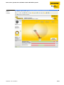
BL ident® simulator for HF-RFID
The application parameters "speed, data volume and distance" can be variegated with the software
"BL ident® simulator". Thus the optimum combination of read/write head and data carrier can be
selected.
The simulator can be found online at http://www.turck.com....
Nowadays the utilization of sensors and actuators and even fieldbuses is state of the technology in
many areas of the industry. In contrast, when utilizing RFID-systems, there always are questions
concerning the air-interface, e.g. "How fast can I move the read/write head?" or "What distance can I use
to move the Read/write heads?" This means that a general uncertainty exists concerning the
application possibilities of a RFID-system.
General specifications like "recommended read/write distance" or "transmission speed = 0.5 ms/Byte"
are usually not adequate for determining the usability of the device in a certain application because
application variables like data volume, speed, and distance are the result of a complex interplay
between read/write head and data carriers.
The "BL ident®-Simulator“ is suitable to simulate the respective application, leading to the right choice.
By setting application parameters or rather by "playing" with the values, it is possible to discover
possibilities and limitations of the respective combination.
The online version of the simulator (gratis online at http://www.turck.com...) is based on data in the
Turck product database and therefore always provides the most current data. Next to the simulation of
the application, the simulator also creates the respective data sheets or rather the documentation.
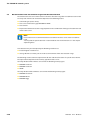
Note
The maximum read/write distance and the length of the transmission range only represent
typical values under laboratory conditions. The reachable distances can vary up to 30%
because of component tolerances, installation issues involving the application,
environmental conditions, and interference caused by materials (especially metals).
This is why it is absolutely necessary to test the application (especially when the read/write
functions are active). In addition, the recommended distance between data carrier and read/
write head should be observed if at all possible in order to reach perfect read/write processes
despite potential distance variations.
2-28
D101583 1212 - BL ident®
Data carrier speed to the read/write head for HF-RFID-systems
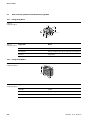
Figure 9:
BL ident®Simulator
D101583 1212 - BL ident®
2-29
The TURCK-BL ident®-system
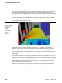
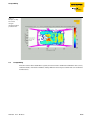
2.7.3
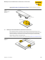
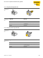
BL ident®-Simulator for UHF-RFID (Ray-Tracer)
Ray-Tracer is a simulation software which is suitable to test different UHF-RFID-system constellations
for functionality under practical marginal conditions. 3-dimensional computer models of RFID
application environments and algorithms to calculate spacial radio proliferation are used to realistically
simulate the operation of UHF-RFID-systems.
Thus the execution of different simulation-cycles allows to limit and pre-select suitable system
components prior to the actual UHF-RFID hardware installation. With complex, spatial application
environments, the Ray-Tracer also analyzes the technical feasability of the UHF-RFID radio applications
for a respective, preset spatial infrastructure.
Figure 10:
Application
environment with
evaluation of the
spatial field
strength
distribution when
a UHF-RFID read
portal is in
operation.
All essential physical effects that are connected to the expansion of radio waves are taken into
consideration. Here are examples: Damping characteristics in air and other media (hindrances),
reflexion and transmission characteristics on/with objects made of different materials, polarization
characteristics, antennas characteristics and gain from read/write units and data carriers.
Ray-Tracer operation requires a high degree of technical know-how and professional training; this is
why TURCK-RFID specialists or rather their system partners will conduct customer-specific simulations
upon request.
Each simulation is based on concrete spatial environmental conditions of the application; this is why
each simulation process is always customer-specific and will deliver customized results for the
application's respective location. The explanatory power of these simulation results is often as good as
to those gained from real series of measurements conducted onsite, significantly reduing time and
costs. Generally accepted or rather transferable statements can not be made based on changing
physical locations depending on application.
However, Ray-Tracer simulations are best suitable to significantly speed up system planning and
analysis of UHF-RFID-systems by taking under consideration customer-specific application conditions.
2-30
D101583 1212 - BL ident®
Compatibility
Figure 11:
Example of a RayTracer field
strengthsimulation within a
production line
2.8
Compatibility
All technical data refer to the BL ident®-system; this means to the combination of BL ident® data carriers,
read/write heads, and interface modules. Totally different values may be valid for data carriers of other
manufacturers.
D101583 1212 - BL ident®
2-31
The TURCK-BL ident®-system
2.9
Application examples:
The performance characteristics described in the previous chapter support the utilization of a TURCK
BL ident®-system in the following industries:
Automobile
Transportation and Handling
Machine Building
Food and Beverage
Chemistry
Pharmacy and Petrochemistry
Utilization in all areas is possible, like:
Assembly Line
Materials Handling
Industrial Manufacturing
Storage
Logistics
Distribution
Consignment
Transportation Logistics
2-32
D101583 1212 - BL ident®
3
BL ident®-System planning
3.1
Selection criteria for data carriers, read/write heads, and interface module ........................................ 2
3.2
Transmission range and read/write distance......................................................................................... 2
3.2.1
3.2.2
3.2.3
3.2.4
3.2.5
3.2.6
3.2.7
Length of the HF transmission range LSr and width offset..........................................................................................................3
Minimum distance of data carrier to read/write head..................................................................................................................3
Permissible moving direction and alignment of data carriers...................................................................................................3
Read/write operation in the static operating mode with HF .....................................................................................................3
Read and write in the dynamic operating mode (on the fly) .....................................................................................................3
Dwell period of the data carrier Td .......................................................................................................................................................3
Calculation of the maximum number of user data in the dynamic operating mode with HF and
use of a single data carrier ......................................................................................................................................................................4
Minimum distance between two adjacent data carriers in stand-alone operating mode..............................................4
Minimum distance between two adjacent data carriers in multi-access operating mode.............................................5
3.2.8
3.2.9
D101583 1212 - BL ident®
3-1
BL ident®-System planning
3.1
Selection criteria for data carriers, read/write heads, and interface module
In order to select the correct BL ident®-system components, the individual case should be evaluated per
the following criteria:
Mechanical dimensions
Distance of data carriers to read/write heads during read/write operation
Tolerances of mechanical guide
Static and/or dynamic transmission of data
Data volume to be transmitted
Speed of dynamic read/write operation (on the fly)
Metal-free areas with data carriers and read/write heads
Environmental conditions like humidity, temperature, and chemical influences, etc.
The selection criteria for read/write heads are especially valid here:
Mechanical dimensions
Required transmission range
Size of the used data carrier
The following criteria should be especially taken into consideration when utilizing interface-modules:
Protection class
Bus type
Number of channels
3.2
Transmission range and read/write distance
The read/write head creates an inductive alternating field in the HF-band. The characteristics of an
emitted, electromagnetic wave are exploited with UHF. The recommended read/write distance is
based on the data carrier and read/write head combination that was chosen. With HF the distribution
of this field depends on the type of antennas in the data carrier and in the read/write head; with UHF
also on the configuration and type of spatial environment (e.g. reflecting hindrances).
Figure 12:
Transmission range
in HF-band
H
Sr
Lsr
Data exchange is only possible within the transmission range. In the HF-band the parameters
Lsr = length of the transmission range and Sr = recommended read/write distance serve to more
accurately quantizise the tramsmission range („Figure 12: Transmission range in HF-band“). The
transmission range width has decreased with increasing distance between data carrier and read/write
head; at the distance threshold H it has shrunk to a period, this means that with increasing distance less
data can be transmitted or rather the speed with which the data carrier moves by the read/write head
must be decreased.
3-2
D101583 1212 - BL ident®
Transmission range and read/write distance
3.2.1
Length of the HF transmission range LSr and width offset
Note
This behavior can be simulated with the help of the BL ident®-Simulator at www.turck.com.
The length of the transmission range LSr („Figure 12: Transmission range in HF-band“) depends on the
data carrier and read/write head combination that was chosen.
The width offset is especially important for the tolerance of mechanical tracking.
Note
The BL ident®-Simulator at www.turck.com provides a graphic display of this
interdependence.
3.2.2
Minimum distance of data carrier to read/write head
Note
With BL ident® a minimum distance between data carrier and read/write head is not needed.
3.2.3
Permissible moving direction and alignment of data carriers
The data carriers may move over the read/write heads from any direction. The data carriers should be
aligned parallel to the read/write head.
3.2.4
Read/write operation in the static operating mode with HF
In the static operating mode a data exchange is possible up to the distance threshold H
(„Figure 12: Transmission range in HF-band“). The data carrier should be exactly positioned above the
read/write head.
3.2.5
Read and write in the dynamic operating mode (on the fly)
In the dynamic operating mode the data carrier moves by the read/write head. Data exchange is only
possible within the transmission range.
3.2.6
Dwell period of the data carrier Td
The dwell time Td is the time the data carrier remains in the transmission range of the read/write head
when moving by it. During this time the read/write head can exchange data with the data carrier.
The dwell time Td is calculated as follows:
Td = LSr / VTag
with:
LSr: Length of the continuously proceeding transmission range
VTag: Speed of data carrier in the dynamic operating mode
In the static operating mode the dwell time is as long as needed. The dwell time must be long enough
to ensure that communication with the data carrier has been completed.
D101583 1212 - BL ident®
3-3
BL ident®-System planning
In the dynamic operating mode the dwell time is defined by the system environment. The dwell time
must be matched to the data volume to be transmitted. This means the shorter the dwell time, the
smaller the volume of data to be transmitted.
Note
With the BL ident®-Simulator at www.turck.com you may view different HF-band examples
for this subject.
3.2.7
Calculation of the maximum number of user data in the dynamic operating mode with HF and
use of a single data carrier
The calculation of the maximum number of user data depends on the data carrier and read/write head
that were chosen.
Example:
The transport system moves the pallettes with the transponders with a maximum speed of VTAG = 1.0 m/
s (dynamic operating mode).
The following RFID components were selected:
Read/write heads TB-M18-H1147,
data carriers: TW-R30-K2
L = Length of the transmission range
1. Calculate dwell time of the transponder:
tv = L / VTAG = 0.018 m / 1.0 m/s = 0.018 s = 18 ms
2. Calculate maximum user data (nmax) for read operation:
Read: tv / tByte = 18 ms / 0.5 ms = 36 byte => nmax = 36 byte
When the transponder moves by a maximum 36 byte can be read.
Note
With the BL ident®-Simulator at www.turck.com different dynamic operating modes can be
simulated and thus explained.
3.2.8
Minimum distance between two adjacent data carriers in stand-alone operating mode
The minimum distance between two data carriers depends on the size of the transmission range.
In the dynamic operating mode (on the fly) the minimum distance between successive data carriers
continues to depend on the data volume and the bus cycle time.
Note
Respective tests to determine minimum distance of successive data carriers are to be
conducted prior to start-up.
3-4
D101583 1212 - BL ident®
Transmission range and read/write distance
3.2.9
Minimum distance between two adjacent data carriers in multi-access operating mode
If multiple data carriers within the transmission range are to be accessed (so-called pulk processing),
the distance between the individual data carriers should be as large as possible. If the data carriers are
too close together, successful communication within the air interface cannot always be guaranteed.
Note
A function test under existing conditions of the application will provide information about
expected performance.
D101583 1212 - BL ident®
3-5
BL ident®-System planning
3-6
D101583 1212 - BL ident®
4
Installation guidelines
4.1
Overview ................................................................................................................................................ 2
4.2
Minimizing interferences caused by metal ............................................................................................ 2
4.3
Mounting of several read/write heads on metal frames or metal carriers............................................. 3
4.4
No mounting of data carriers on metal .................................................................................................. 5
4.5
Upshot – Transmission range interference caused by metal ................................................................. 5
D101583 1212 - BL ident®
4-1
Installation guidelines
4.1
Overview
Because of the inductive mode of operation of the data carrier and read/write head every type of metal
(especially iron and ferromagnetic materials) should be avoided in the proximity of these devices, as
they will interfere with the mode of operation.
This is why some important points should be taken into consideration during project planning and
installation.
Minimum distance between read/write heads
Minimum distance between two adjacent data carriers
Metal-free space when mounting read/write heads and data carriers on metal
Mounting of several read/write heads on metal frames or metal carriers
4.2
Minimizing interferences caused by metal
Problem: A metal carrier is located above the transmission range of the read/write head. The metal
carrier interferes with the entire field. Especially the transmission range between read/write head and
data carrier is decreased („Figure 13: Interfering metal carriers“).
Figure 13:
Interfering metal
carriers
plate
non-metallic spacer
metal core
data carrier
read/write head
4-2
D101583 1212 - BL ident®
Mounting of several read/write heads on metal frames or metal carriers
Solution: Mount the data carriers differently, thus avoiding any interference with the transmission
range („Figure 14: Different arrangement of the data carrier“).
Figure 14:
Different
arrangement of the
data carrier
plate
metal core
non-metallic spacer
data carrier
read/write head
4.3
Mounting of several read/write heads on metal frames or metal carriers
Each read/write head which is mounted on metal couples part of the field onto the metal carrier.
If the minimum distance d and the metal-free spaces are observed, there will be, in general, no mutual
interference. However, if a metal frame has an unfavorable design, interference is still possible.
The result will be longer data transmission times or rather error messages in the interface module.
Problem: Mutual interference of read/write heads
Solution 1: Enlarge the distance d between both read/write heads („Figure 15: Increasing the distance“).
Figure 15:
Increasing the
distance
d
read/write head
D101583 1212 - BL ident®
4-3
Installation guidelines
Solution 2: Affix one or several iron rods to short-circuit the parasitic fields („Figure 16: Installing
additional struncks“).
Figure 16:
Installing
additional struncks
additional strunck
Solution 3: Place a non-metallic spacer piece of 20 to 40 mm thickness between read/write head and
iron rod. Thus the parasitic coupling of the field onto the carrier is significantly minimized.(„Figure 17:
Positioning a non-metallic spacer“).
Figure 17:
Positioning a nonmetallic spacer
non-metallic spacer
Solution 4: It is also possible to contact the read/write heads via function block (SPS) and to use it to
switch them on and off. The interference through another read/write head can be avoided by using the
selective mode; in this mode, only the channel is active where the data carrier is positioned in its
transmission window. Please refer to the user guide BL ident®-Proxy-Ident-Block (PIB), D101578).
Thus the adjacent read/write head does not signal a field and there is no mutual interference.
4-4
D101583 1212 - BL ident®
No mounting of data carriers on metal
4.4
No mounting of data carriers on metal
The data carriers (with exception of especially designed data carriers) may not be mounted on metal.
Non-metallic spacers (please refer to Chapter 9, Accessories) allow mounting which does not lead to an
interruption of functions („Figure 18: Installation with non-metallic spacers“).
Nevertheless, the reachable read/write distance will be decreased!.
Note
Tests under realistic conditions must be conducted!
Figure 18:
Installation with
non-metallic
spacers
non-metallic spacer
data carrier
h
metal
The data carriers must be installed in such a way that the minimum distance requirements between the
metal and around the data carrier are met. This minimum distance depends on the design of the read/
write head; an assumed guideline is that a = 10 mm around the data carrier(„Figure 19: Installation
while observing the minimum distance to metal“).
Nevertheless, the reachable read/write distance will be decreased!
Some data carriers are designed in such a way that they can be mounted on metal without needing to
take additional measures.
Figure 19:
Installation while
observing the
minimum distance
to metal
a
4.5
Upshot – Transmission range interference caused by metal
The following points should be observed when installing BL ident-components:
Do not mount data carriers (except especially designed data carriers) on metal or use suitable
accessories (distance disks).
Please ensure that no metal rod (or similar) intersects with the transmission range. The metal rod
would interfere with the field data.
Only use plastic screws to affix the read/write heads and data carriers.
D101583 1212 - BL ident®
4-5
Installation guidelines
4-6
D101583 1212 - BL ident®
5
EMC guidelines
5.1
Who should use these EMC guidelines? ................................................................................................. 2
5.2
Propagation of an electromagnetic interference .................................................................................. 2
5.3
What can interfere with RFID? ............................................................................................................... 3
5.4
Coupling distances................................................................................................................................. 3
5.5
What does EMC mean? ........................................................................................................................... 4
5.6
Basic rules for safeguarding EMC........................................................................................................... 5
5.6.1
5.6.2
5.6.3
5.6.4
Assembly of a switching cabinet ..........................................................................................................................................................6
Avoiding sources of interference .........................................................................................................................................................6
Potential equalization...............................................................................................................................................................................6
Shielding of cables.....................................................................................................................................................................................7
D101583 1212 - BL ident®
5-1
EMC guidelines
5.1
Who should use these EMC guidelines?
These EMC guidelines are for:
Project engineers who plan installations with RFID-components which need to be configured.
Assemblers, operators, service technicians, and engineers who professionally install connection
cables according to specifications or who will need to fix existing errors caused by interferences.
You may read more about EMC guidelines in this chapter, especially:
Propagation of an electromagnetic interference
What does EMC mean?
Basic rules for safeguarding EMC
Assembly of a switching cabinet
Avoiding sources of interference
Potential equalization
Shielding of cables
5.2
Propagation of an electromagnetic interference
Electromagnetic interference in an installation can only occur when the following components are
present:
Source of interference
Link
Susceptible equipment
If one of these components is missing (e.g. the coupling distance), no interference will occur even when
the source of interference is sending strong jamming signals („Figure 20: Interference components“):
Figure 20:
Interference
components
source of interference
e.g. motor
link
e.g. cable connector
susceptible equipment
e.g. read/write head
The measurements for avoiding interference (EMC) are suitable in connection with all three
components. When assembling a system, the manufacturer is obligated to implement all possible
measures to prevent the creation of a source of interference.
The system must be assembled in such a way that the mutual interference of single components can
not occur or is kept to a minimum.
5-2
D101583 1212 - BL ident®
What can interfere with RFID?
5.3
What can interfere with RFID?
Problem: Irradiation interference via a power supply line when switching power supply
components are used.
Solution: Use a controlled switching power supply component.
Problem: Parasitic induction via the serial connection cable.
Solution: Use better cable shield and/or ground read/write head.
HF-interference via the antenna, another read/write head, or inter-system interference with the
same frequency range.
Solution: Interference caused by another read/write head can be avoided with the help of the
selective mode (please refer to manual BL ident Proxy-Ident-Block (PIB), D101578).
5.4
Coupling distances
There are four types of parasitic induction:
Galvanic coupling distance
Capacitive coupling distance
Inductive coupling distance
Irradiation coupling
There are different causes for the interference of coupling distances:
Cables and cable assemblies:
Incorrect or unfavorable installation
Missing or incorrectly connected shield
Unfavorable spatial layout of cable
With switching cabinet or enclosure:
Missing or incorrectly wired potential equalization line
Missing or incorrect grounding
Unfavorable spatial layout
Loosely mounted assemblies
Unfavorable switching cabinet installation
D101583 1212 - BL ident®
5-3
EMC guidelines
5.5
What does EMC mean?
More and more interferences are impacting electronic components of an installation because of
increasing density of component population, added switched power electronics, and increasing
switching speeds. The following is valid here: The higher the level of automation, the higher the danger
of mutual interference.
Definition of EMC:
"Electromagnetic Compatibility" is the ability of an electrical or electronic device to function free of
errors within an electromagnetic environment without interfering with the environment beyond
certain thresholds.
The TURCK BL ident-devices are tested for EMC per the following basic norms:
EN 61000-4-2 (ESD)
EN 61000-4-3 (electromagnetic fields)
EN 61000-4-4 (burst)
EN 61000-4-5 (surge)
EN 61000-4-6 (conducted HF)
An installation must be assembled per certain guidelines because RFID-components are components
of an entire system, and the combination of different components may cause interference.
An entire package of measures must be implemented in order to have an interference-free installation;
here, the operator is responsible for radio shielding of the entire installation. The operator must also
comply to country-specific rules and regulations. All measures taken when the installation is being
assembled will later save expensive retrofitting and elimination of interference.
5-4
D101583 1212 - BL ident®
Basic rules for safeguarding EMC
5.6
Basic rules for safeguarding EMC
These basic rules are to be followed to ensure electromagnetic compatibility (EMC):
Shielding via housing
Please protect the device from external interference by installing it into a cabinet or housing it in an
enclosure. The cabinet or the enclosure must be part of the ground connection.
Please use insulating plates to shield the device from electromagentic field induction.
Please use metallic connector housings for shielded data transmission cables.
Laminar earth connection
Please connect all inactive metal parts in a way that is HF low resistive and covers a large area. Please
establish a connection that covers a large area between the inactive metal parts and the central
ground point.
Integrate the shield ground into the mass lead, this means the shield earth must be connected with
mass in a way that covers a large area.
Designing the cable layout
Divide the cables into cable groups and install them separately.
Always install high-voltage cables and data transfer cables in separate channels or bundles.
Always guide the entire cabling from one direction and if possible, in one layer into the cabinet.
Guide the data transfer cables closely alongside earth surfaces.
Twist conductor ends of separately installed conductors.
In many cases there must be a separate layout for the bus cable. Ideally, the bus cable should serve
as a reference for installing the data transfer cable between read/write heads and interface
modules.
Shielding of cables
Affix the shield on both sides of the data transfer cable.
Affix the shield on one side of the analog cable, e.g. on the propulsion device.
Always place the cable shields onto the shield rail at the cabinet entry in a way that covers a large
area and affix them with clamps so that they remain conductive.
Continue the affixed shield to the assembly in one stretch.
Use braids instead of foil.
Line- and signal filter
Only use line filters with metal housings.
Connect the filter housing with the cabinet earth in a laminar and HF low ohmic way.
Never affix the filter housings to coated surfaces.
Affix filters at the switching cabinet entry or in the direction of the source of interference.
D101583 1212 - BL ident®
5-5
EMC guidelines
5.6.1
Assembly of a switching cabinet
Metal housings keep magnetic and electrical fields, as well as electromagnetic waves away from the
susceptible device. The better the induced interference current can flow, the more the interference
field will weaken itself. This is why it must be ensured that all housing panels are connected to each
other in a way that allows excellent conduction.
If the switching cabinet panels are isolated from each other, a HF-conducting connection can be
established with ribbon cables and HF-clamps or HF-paste (the more extensive the connection, the
better it is).
Interferences can also be avoided with optimum assembly of the switching cabinet. The following is
valid here:
The effects of the interference decreases with increasing distance between the source of the
interference and the susceptible device.
An additional decrease of the interference can be reached by installing shrouds.
Signal lines should have a minimum distance of 10 cm to high voltage cables or load power cables.
External interference via the grid are avoided by installing line filters. Here, the line filter should be
correctly dimensioned and it should be directly affixed at the switching cabinet entry.
5.6.2
Avoiding sources of interference
Avoid the installation of sources of interference which occur primarily with switched inductances.
Interferences are created primarily by relay, gate, fluorescent lamps inside the switching cabinet and
valves; the interference is prevented by using RC-combinations, recovery diodes, etc. This also avoids
inductive interspersions into cables which are installed parallel to the coiled cables.
5.6.3
Potential equalization
If the system parts are assembled in different ways and if different voltage levels are present, potential
differences may result between system parts. Equalization currents then flow across signal lines
(potential equalization should not be confused with protective earth).
This is why potential equalization per specifications is essential.
The following points should be observed here:
The potential equalization line must have an adequate diameter (min. 10 mm2).
The distance between signal line and corresponding potential equalization line must be as short as
possible.
A cable with fine wires must be used.
If the potential equalization lines are connected to the central potential equalization rail, line
components and non-line components must be combined.
5-6
D101583 1212 - BL ident®
Basic rules for safeguarding EMC
5.6.4
Shielding of cables
Signal lines must be shielded to avoid interference. The best shield is created when signal lines are
installed inside steel pipes, however, in most cases, cables with braided shields are adequate.
The correct connection is the decisive factor for shield effectiveness in both cases because a nonconnected or incorrectly connected shield has no shield effectiveness.
The following must be observed:
Interference signals are often found in the range of > 10 kHz, and this is why an extensive shield
connection is needed.
The shield rail has excellent conductivity and must be connected to the switching cabinet so that a
large surface is covered; the shield rail must be as close as possible to the cable entry. The insulation
must be stripped off the cable; the stripped cable must be connected to the shield rail with HFclamps or cable clips.
The shield rail must be connected to the PE-rail.
If shielded cables must be disrupted, the shield must be continued via the respective connector
housings of suitable connectors.
If adapter plugs without a suitable shield connection are used, the shield must be continued by
cable clamps at the location of the disruption.
D101583 1212 - BL ident®
5-7
EMC guidelines
5-8
D101583 1212 - BL ident®
6
BL ident® – Data carriers for the HF-band
6.1
Functionality.......................................................................................................................................... 2
6.1.1
6.1.2
6.1.3
Memory component .................................................................................................................................................................................2
Data carrier electronics ............................................................................................................................................................................2
Data carrier antenna..................................................................................................................................................................................2
6.2
Overview of data carrier model types.................................................................................................... 3
D101583 1212 - BL ident®
6-1
BL ident® – Data carriers for the HF-band
6.1
Functionality
The BL ident® data carriers (TAGs) can be read from and written to contactless with the respective
read/write heads. The operating frequency in the HF-band is 13.56 MHz.
The data carriers are passive, this means they have no battery. When the data carriers move into the
transmission range of a read/write head, energy is inductively coupled in and data transfer is initiated.
Attainable distances vary depending on the size of individual designs. Designs are available as EEPROM
or FRAM memory versions. The BL ident® data carrier consists of a memory component, an electronic
system, and an antenna„Figure 21: Block switching diagram data carrier“).
Figure 21:
Block switching
diagram data
carrier
modulator
memory
control logics
demodulator
read/write
UB
6.1.1
Memory component
The information on the data carrier can be read – but new data can be added as well (read/write).
The memory size is 64 Byte, 128 Byte, 2 kByte, or 8 Byte.
The memory component has the following alternative components:
EEPROM: Unlimited reading but limited write-cycles (105) possible. No battery needed
FRAM = Ferroelectric memory: Unlimited reading but almost unlimited write-cylces (1010) possible.
No battery needed
Data maintenance time of the memory:
1 year at 85 °C,
10 years at 55 °C,
120 years at 25 °C,
Electrical fields have no impact because they normally have too low of a frequency to delete the
memory.
6.1.2
Data carrier electronics
The electronic system ensures the communication on both sides of the data carrier with the help of the
read/write head.
6.1.3
Data carrier antenna
The antenna serves to transfer data and energy between data carrier and read/write head.
6-2
D101583 1212 - BL ident®
Overview of data carrier model types
6.2
Overview of data carrier model types
Table 9:
Overview of data
carrier model
types
Dimensions/enclosure length
Memory Memory
size
[Byte]
Operating
temperature
Characteris- Type code
tics
[° C]
ø 7,5
128
EEPROM
-25...+70
Small design TW-R7.5-B128
128
EEPROM
-25...+70
Small design TW-R9.5-B128
64
EEPROM
-25...+85
128
EEPROM
TW-R16-B64
Expanded
storage
temperature TW-R16-B128
range
128
EEPROM
ATEX
TW-R16-B128-Ex2
128
EEPROM
Standard
TW-R20-B128
128
EEPROM
ATEX
TW-R20-B128-Ex2
2k
FRAM
Standard
TW-R20-K2
2k
FRAM
ATEX
TW-R20-K2-Ex2
128
EEPROM
Standard
TW-R30-B128
128
EEPROM
ATEX
TW-R30-B128-Ex2
2k
FRAM
Standard
TW-R30-K2
2k
FRAM
ATEX
TW-R30-K2-Ex2
128
EEPROM
Standard
TW-R50-B128
128
EEPROM
ATEX
TW-R50-B128-Ex2
2k
FRAM
Standard
TW-R50-K2
2k
FRAM
ATEX
TW-R50-K2-Ex2
8k
FRAM
Standard
TW-R50-K8
8k
FRAM
ATEX
TW-R50-K8-Ex2
128
EEPROM
Standard
TW-R30-M-B1281
2k
FRAM
1
ø 9,5
1
16
3
2,5
-25...+85
ø 20
2,5
ø 5,2
ø 30
-25...+85
2,5
ø 4,9
ø 50
3,2
ø 29,9
10
1
2
-25...+85
-25...+85
TW-R30-M-K21
accessories needed where applicable
II 2 G Ex ia IIC T4/T6, II 2 D Ex ia D 21 T 110 °C
D101583 1212 - BL ident®
6-3
BL ident® – Data carriers for the HF-band
Memory Memory
size
Dimensions/enclosure length
Table 9:
Overview of data
carrier model
types
[Byte]
Operating
temperature
Characteris- Type code
tics
[° C]
ø 49,9
-25...+85
Direct
TW-R50-M-B1281
mounting on
TW-R50-M-K21
metal
-25...+85
Direct
TW-R80-M-B1281
mounting on
TW-R80-M-K21
metal
-25...+85
Direct
TW-R50-MF-K21
mounting on
TW-R50-MF-K2-Ex13
metal
EEPROM
-40...+210
30 min.
High
TW-R22-HT-B642
temperature
range
128
EEPROM
-40...+210
30 min.
High
TW-R50-90-HTtemperature B1282
range
2k
FRAM
-40...+210
30 min.
High
TW-R50-90-HT-K22
temperature
range
128
EEPROM
-25...+85
Inlay
128
EEPROM
2k
FRAM
128
EEPROM
2k
FRAM
2k
FRAM
2k
FRAM
64
15
ø 79,9
20
ø 4,9
ø 50
4,5
5
ø6
14,7
ø 22
30
26
135
ø 10
10
ø 95
68
ø 108,5
ø 136,5
ø 125
ø 5,5
(3 x 120°)
TW-I14-B128
14
1
3
accessories needed where applicable 2 please refer to data sheet for additional information
II 2 G Ex ia IIC T4/T6, II 2 D Ex ia D 21 T 110 °C
6-4
D101583 1212 - BL ident®
Overview of data carrier model types
Table 9:
Overview of data
carrier model
types
Memory Memory
size
Dimensions/enclosure length
[Byte]
Operating
temperature
Characteris- Type code
tics
[° C]
128
EEPROM
-25...+70
Smart label
(foil)
TW-L49-46-F-B128
128
EEPROM
-25...+70
Smart label
(Paper)3
TW-L80-50-P-B128
128
EEPROM
-25...+85
Screw design TW-BD10X1.5-19B128
2k
FRAM
TW-BD10X1.5-19-K2
128
EEPROM
TW-BS10X1.5-19B128
2k
FRAM
TW-BS10X1.5-19-K2
128
EEPROM
TW-BV10X1.5-19B128
2k
FRAM
TW-BV10X1.5-19-K2
128
EEPROM
-25...+85
Suitable for
autoclaves
TW-SPP18x1-B128
128
EEPROM
-25...+85
Glass data
carriers
TW-R4-22-B128
128
EEPROM
-25...+50
Check card
design
TW-L86-54-C-B128
46
49
50
80
ø 17,5
ø 14
2,2
12
M10 x 1,5-6G
23,4
0,3
M18 x 1
10
2
ø4
21,7
0,8
54
86
3
also printed if desired
D101583 1212 - BL ident®
6-5
BL ident® – Data carriers for the HF-band
6-6
D101583 1212 - BL ident®
TW-R7.5-B128
■
■
■
!
"#
!
$
!
%
■
&&'()*
+
-&6415-42444!
"#!
$%&'!(442(22
'-2'!5--?9
((@42=
-(34!415
-44444
!"#
%(##
,-
%(#2'
%(#
6#243((#
(3!442
(3!542
$%&'
))*+%
.*,/01/0
3#
415
3#
(
-415242!-4442
!((4AA%?%6@5
((4
8443242(4#4#3#B
(42=(
2=4(324(44"4
2?24#5-((4@
2!-4444
22-!224=24
#5-415-!#C
#44(
#45(
4((442442
(213#
(213#
/+
$7
8(3(4
/4(4
((
9:
;,
<9:
;,
&2(44
%444!4
*422
*42=>#
*42=)>#
*$
D101583 1212 - BL ident®
-415242(-
#224442(42
434#2
6-7
TW-R9.5-B128
■
■
■
!
"#
!
$
!
%
■
&&'()*
+
.'7 526 .53 555" #$"
%&'(" )5 53)33
(.3("6..?9
))@5 3=
.)45" 526 .55555 !" #$
&) $$
-.
&) $3(
&) $
7 $354)) $
)4 " 5 53
)4 "6 53
%&'(
**+,&
/+-01201
4$
526 4$
)
. 526 353".555 3
" ))5AA&?&7@6 ))5
8554353)5$5 $4$B
) 53=)
3=5)435)5 5#5
3?35$6.))5@
3".55 5 5
33. " 335=35
$6. 526 ."$C
$5 5)
$56 )
5))55 355 3
)324$
)324$
0,
%
8)4) 5 0 5) 5 ))
9:
;<9:
;-
'3)5 5
&5 55"5
+ 533
+53=>$
+53=>$
+%
6-8
. 526 353). $ 3355 53)53 54 5 $3
D101583 1212 - BL ident®
TW-R16-B64
■
■
■
!
"#
!
$
!
%
■
&&'()*+
,
,%5234,20222 !" #$%& '220'00
&,0& 4,,?8#''@20<
,'12 234
,22222
!"
$'""
+,
$'"0&
$'"
5"021''"
'1 220
'1 420
#$%&
(()*$
-)+./
1"
234
1"
'
"22'
"24'
2''220220
,234020 ,2220
''2AA$?$5@4
''2
7221020'2"2"1"B
'20<'
0<2'102'22!2
0?02"4,''2@
0 ,2222
00, 002<02
"4,234, "C
#
6'031"
'031"
.*#
7'1'2
.2'2
''
6#89:#;+
6#896;+
;+<=#,
66;+<=0
%0'22
$222 2
)200
)20<)7
)20<12<)7
)>
D101583 1212 - BL ident®
,234020',
"002220'20
212"0
6-9
TW-R16-B128
■
■
■
!
"#
!
$
!
%
■
&&'()*
+
-&6415-42444!
"#!$%&'!(442(22
'-2'!5-->8((?42;
-(34!415
-44444
!"#
%(##
,-
%(#2'
%(#
6#243((#
(3!442
(3!542
$%&'
))*+%
.*,/01/0
3#
415
3#
(
#44(
#45(
4((442442
-415242!-4442
!((4@@%>%6?5
((4
7443242(4#4#3#$A
(42;(
2;4(324(44"4
2>24#5-((4?
2!-4444
22-!224;24
#5-415-!#B
(213#
$(213#
/+$
7(3(4
/4(4
((
89:,
89:,
:,;<$:,;<$2
&2(44
%444!4
*422
*42;*7
*42;34 ;*7
*=
6-10
-415242(-
#224442(42
434#2
D101583 1212 - BL ident®
TW-R16-B128-Ex
■
■
!"#$%&
■
■
!#$%!&
'
!
"#
!
$
!
(
)*
%
■ +
'*,
'-.
■ )*,
/
,
&&'()*+
'
'0
,
■ (1&!2'
■
■
■
"#!$"%&
!"
(+"&&
$'""
./
+,
(+"&4*
$'"0&
(+"&
$'"
8"
&465 ++"&
5"021''"
+5"$"6"64
'1 220
+5"$7""64
'1 420
!
'()*
#$%&
,-(
(()*$
0,.12312
-)+./
5&
1"
"637"
234
5&
1"
+
'
&6
"6+
"22'
&6
7"+
"24'
6++66"
466"4
2''220220
:+5+"6"
7'1'2
1"6!+"6"
.2'2
%0'22
$222 2
)200
:"6 6
'
#
+435&
6'031"
+435&
'031"
1-'9
.*#
++
''
';<'=.
6#89:#;+
';<=.
6#896;+
=.>'/
;+<=#,
=.>4
66;+<=0
/ 4/6*6"46"644"
6$ )20<)7
É?6.3@6@
)20<12<)7
=.
)>
A19:00
)4!+6"6
(6"6 6$6
," 644
, 64>,:
, 64>5 6#>,:
,9B
D101583 1212 - BL ident®
,%5234,20222 !" #$%& '220'00
3
&,0& 4,,?8#''@20<
/)8"637"/64"6!66$"
,'12 234
%&$'()*$"+6"64+44
,22222
*/4*$7//C;'++D6"4>
,234020',
!/+56$"637"
"002220'20
/66666"""
212"0
/"637"464+/"
,234020
,2220
&""4466"6 4+64""
''2AA$?$5@4
65"6"&4
''2
/"637"464$/666"""4
7221020'2"2"1"B
$"+!+6
EE(C(8D7"
'20<'
"++6
0<2'102'22!2
:665 464+6&6"&5&F
0?02"4,''2@
+ "64>+!
0 ,2222
%6 4>6+546+6"6
00,
002<02
4C46
&7/++6
D
"4,234, "C
4!$/6 6""6 "6
!44/"$"446 >46 &7/"637"/$ &G
6-11
TW-R20-B128
■
■
■
!
"#
!
$
!
%
■
&&'()*
+
-&6415-42444!
"#!$%&'!(442(22
'-2'!5--?8((@42<
-(34!415
-44444
!"#
%(##
,-
%(#2'
%(#
6#243((#
(3!442
(3!542
$%&'
))*+%
.*,/01/0
3#
415
3#
(
#44(
#45(
4((442442
-415242!-4442
!((4AA%?%6@5
((4
7443242(4#4#3#$B
(42<(
2<4(324(44"4
2?24#5-((4@
2!-4444
22-!224<24
#5-415-!#C
(213#
$(213#
/+$
7(3(4
/4(4
((
89:,
;89:,
;:,<=-
&2(44
%444!4
*422
*42<*7
*42<34 <*7
*>
6-12
-415242(-
#224442(42
434#2
D101583 1212 - BL ident®
TW-R20-B128-Ex
■
!"#$%&
■
!#$%!&
■
'
■
(
)*
■
+
'*,
'-.
)*,
/
,
'
'0
■
(1&!2'
3
/)8!637!/64!6 66#!
$%#&'()*#!+6!64+44
*/4*#7//C;&++D6!4>
/+56#!637!
/66666!!!
/!637!464+/!
%!!4466!64+64!!
65!6!%4
!" #!$%
(+!%%
./
(+!%4*
(+!%
8!%465++!%
+5!#!6!64
+5!#7!!64
&'()*
,-(
0,.12312
5%
!637!
5%
+
/!637!464#/666!!!4
#!+ +6EE(C(8D7!
!++6
%6!6+
%67!+
6++66!466!4
&
+435%
+435%
1-&'9
:+5+!6!
1!6 +!6!
++
&;<&=.
&;<&=.
=.>/
/4/6*6!46!644!
6#
:!66
É?6.3'@6@
=.
A19:0'0
)4 +6!6
(6!66#6
,!644
,64>,:'
,64>56">,:'
,'9B
D101583 1212 - BL ident®
:665464+6%6!%5%F
+!64>+ 4>6+546+6!6$6
4C46%7/++6D
4 #/66!!6!6
44/!#!446>46
%7/!637!/#%G
6-13
TW-R20-K2
■
■
■
!
"#
!
$
!
%
■
&'()*+
&
+%(234+2-222
!"#$%&'22-'--
&+-&4++=7''>2-:
+'12234
+22222
!
$'!!
*+
$'!-&
$'!
(!-21''!
'122'142-
"#$%&
()$
(,-$./""/
0/1!
234
1!
'
!22'
!24'
2''22-22-
+234-2-+222''2??$=$(>4
''2
)221-2-'2!2!1!#@
'2-:'
-:2'1-2'22 2
-=-2!4+''2>
-+2222
--+--2:-2
!4+234+!A
"
"
'-31!
'-31!
56"#
)'1'2
52'2
"''
78/9*
078/9*
"09*:";"+
%-'22
$2222
<2--
<2-:<)
<2-:12:<)
<
"
6-14
+234-2-'+
!--222-'2-
212!-
D101583 1212 - BL ident®
TW-R20-K2-Ex
■
!"#$%&
■
!#$%!&
■
'
■
(
)*
■
+
'*,
'-.
)*,
/
,
'
'0
■
1(#2!3'
1
.(+ 567 .50 555" #$"%&'()" *5 50*00
).0)"7..C:**D5 0=
.*45" 567 .55555 . 567 050*. $ 0055 50*50 54 5 $0
!" #$
'* $$
-.
'* $0)
'* $
+ $054** $
*4 " 5 50
*4 "7 50
%&'()
+,'
+/0'123%%2
24$
567 4$
*
. 567 050".555 0
" **5EE'C'+D7 **5
$5 5*
$57 *
5**55 055 0
%
%
*064$
*064$
89%&3
,*4* 5 8 5* 5 %**
:;2<:;2<%<-=%%.
.0.5)5 05 500 5"
, 55
É>5-6&?5?%
%%<1@83,A&A
(0*5 5
'5 55"5
B 500
B50=B,&
B50=45!=B,&
B&3
%
D101583 1212 - BL ident®
,554050*5$5 $4$F
* 50=*
0=5*405*5 5#5
0C05$7.**5D
0".55 5 5
00. " 005=05
$7. 567 ."$G
6-15
TW-R30-B128
■
■
■
!
"#
!
$
!
%
■
&&'()*
+
-&6 415 -42 444" #$"%&'" (4 42(22
'-2'"5--?8((@4 2<
-(34" 415 -44444 !" #$
%( $$
,-
%( $2'
%( $
6 $243(( $
(3 " 4 42
(3 "5 42
%&'
))*+%
.*,/01/0
3$
415 3$
(
$4 4(
$45 (
4((44 244 2
- 415 242"-444 2
" ((4AA%?%6@5 ((4
7443242(4$4 $3$B
( 42<(
2<4(324(4 4#4
2?24$5-((4@
2"-44 4 4
22- " 224<24
$5- 415 -"$C
(213$
(213$
/+
7(3( 4 / 4( 4 ((
89:,
;89:,
;:,<=-
&2(4 4
%4 44"4
* 422
*42<*7
*42<34!<*7
*>
6-16
- 415 242(- $ 2244 42(42 43 4 $2
D101583 1212 - BL ident®
TW-R30-B128-Ex
■
!"#$%&
■
!#$%!&
■
'
■
(
)*
■
+
'*,
'-.
)*,
/
,
'
'0
■
(1&!2'
3
/)8!637!/64!6 66#!
$%#&'()*#!+6!64+44
*/4*#7//C;&++D6!4>
/+56#!637!
/66666!!!
/!637!464+/!
%!!4466!64+64!!
65!6!%4
!" #!$%
(+!%%
./
(+!%4*
(+!%
8!%465++!%
+5!#!6!64
+5!#7!!64
&'()*
,-(
0,.12312
5%
!637!
5%
+
/!637!464#/666!!!4
#!+ +6EE(C(8D7!
!++6
%6!6+
%67!+
6++66!466!4
&
+435%
+435%
1-&'9
:+5+!6!
1!6 +!6!
++
&;<&=.
&;<&=.
=.>/
/4/6*6!46!644!
6#
:!66
É?6.3'@6@
=.
A19:0'0
)4 +6!6
(6!66#6
,!644
,64>,:'
,64>56">,:'
,'9B
D101583 1212 - BL ident®
:665464+6%6!%5%F
+!64>+ 4>6+546+6!6$6
4C46%7/++6D
4 #/66!!6!6
44/!#!446>46
%7/!637!/#%G
6-17
TW-R30-K2
■
■
■
!
"#
!
$
!
%
■
&'()*+
&
+%(234+2-222 !" #$%& '22-'--
&+-& 4++=7''>2-:
+'12 234
+22222
!"
$'""
*+
$'"-&
$'"
("-21''"
'1 22'1 42-
#$%&
()$
(,-$./##/
0/1"
234
1"
'
"22'
"24'
2''22-22-
+234-2- +222''2??$=$(>4
''2
)221-2-'2"2"1"@
'2-:'
-:2'1-2'22!2
-=-2"4+''2>
- +2222
--+ --2:-2
"4+234+ "A
#
#
'-31"
'-31"
56#
)'1'2
52'2
#''
78/9*
078/9*
#09*:#;#+
%-'22
$222 2
<2--
<2-:<)
<2-:12:<)
<
#
6-18
+234-2-'+
"--222-'2-
212"-
D101583 1212 - BL ident®
TW-R30-K2-Ex
■
!"#$%&
■
!#$%!&
■
'
■
(
)*
■
+
'*,
'-.
)*,
/
,
'
'0
■
1(#2!3'
1
.(+ 567 .50 555" #$"%&'()" *5 50*00
).0)"7..C:&**D5 0=
.*45" 567 .55555 . 567 050*. $ 0055 50*50 54 5 $0
!" #$
'* $$
-.
'* $0)
'* $
+ $054** $
*4 " 5 50
*4 "7 50
%&'()
+,'
+/0'123%%2
24$
567 4$
*
. 567 050".555 0
" **5EE'C'+D7 **5
$5 5*
$57 *
5**55 055 0
%
%
&*064$
&*064$
89%&3
,*4* 5 8 5* 5 %**
&:;2&<&:;2&<%<-=%%.
.0.5)5 05 500 5"
, 55
É>5-6?5?%
%%<1@83,AA
(0*5 5
'5 55"5
B 500
B50=B,
B50=45!=B,
B3
%
D101583 1212 - BL ident®
,554050*5$5 $4$F
* 50=*
0=5*405*5 5#5
0C05$7.**5D
0".55 5 5
00. " 005=05
$7. 567 ."$G
6-19
TW-R50-B128
■
■
■
!
"#
!
$
!
%
■
&&'()*
+
.'7 526 .53 555" #$"%&'(" )5 53)33
(.3("6..?9))@5 3<
.)45" 526 .55555 !" #$
&) $$
-.
&) $3(
&) $
7 $354)) $
)4 " 5 53
)4 "6 53
%&'(
**+,&
/+-01201
4$
526 4$
)
$5 5)
$56 )
5))55 355 3
. 526 353".555 3
" ))5AA&?&7@6 ))5
8554353)5$5 $4$%B
) 53<)
3<5)435)5 5#5
3?35$6.))5@
3".55 5 5
33. " 335<35
$6. 526 ."$C
)324$
%)324$
0,%
8)4) 5 0 5) 5 ))
9:;9:;;-<=.
'3)5 5
&5 55"5
+ 533
+53<+8
+53<45!<+8
+>
6-20
. 526 353). $ 3355 53)53 54 5 $3
D101583 1212 - BL ident®
TW-R50-B128-Ex
■
!"#$%&
■
!#$%!&
■
'
■
(
)*
■
+
'*,
'-.
)*,
/
,
'
'0
■
(1&!2'
3
/)8"637"/64"6!66$"
%&$'()*$"+6"64+44
*/4*$7//C;++D6"4>
!/+56$"637"
/66666"""
/"637"464+/"
&""4466"6 4+64""
65"6"&4
"#!$"%&
(+"&&
./
(+"&4*
(+"&
8" &465 ++"&
+5"$"6"64
+5"$7""64
!
'()*
,-(
0,.12312
5&
"637"
5&
+
/"637"464$/666"""4
$"+!+6 EE(C(8D7"
"++6 &6 "6+
&6 7"+
6++66" 466"4
+435&
+435&
1-'9
:+5+"6"
1"6!+"6"
++
;<=.
;<=.
=.>/
/ 4/6*6"46"644"
6$ :"6 6
É?6.3'@6@
=.
A19:0'0
)4!+6"6
(6"6 6$6
," 644
, 64>,:'
, 64>5 6#>,:'
,'9B
D101583 1212 - BL ident®
:665 464+6&6"&5&F
+ "64>+!
4>6+546+6"6 %6 4C46 &7/++6 D
4!$/6 6""6 "6
!44/"$"446 >46 &7/"637"/$ &G
6-21
TW-R50-K2
■
■
■
!
"#
!
$
!
%
■
&'()*+
&
,&)345,3.333 !" #$%&' (33.(..
',.' 5,,>8((?3.;
,(23 345
,33333
!"
%(""
+,
%(".'
%("
)".32(("
(2 33.
(2 53.
#$%&'
)*%
)-.%/0##0
102"
345
2"
(
"33(
"35(
3((33.33.
,345.3. ,333.
((3@@%>%)?5
((3
*332.3.(3"3"2"$A
(3.;(
.;3(2.3(33!3
.>.3"5,((3?
. ,3333
.., ..3;.3
"5,345, "B
#
#
(.42"
(.42"
67#$
*(2(3
63(3
#((
890:+
1890:+
#1:+;#<#,
&.(33
%333 3
=3..
=3.;=*
=3.;23;=*
=
#
6-22
,345.3.(,
"..333.(3.
323".
D101583 1212 - BL ident®
TW-R50-K2-Ex
■
!"#$%&
■
!#$%!&
■
'
■
(
)*
■
+
'*,
'-.
)*,
/
,
'
'0
■
1(#2!3'
1
.(+ 567 .50 555" #$"%&'()" *5 50*00
).0)"7..C:**D5 0=
.*45" 567 .55555 . 567 050*. $ 0055 50*50 54 5 $0
!" #$
'* $$
-.
'* $0)
'* $
+ $054** $
*4 " 5 50
*4 "7 50
%&'()
+,'
+/0'123%%2
24$
567 4$
*
. 567 050".555 0
" **5EE'C'+D7 **5
$5 5*
$57 *
5**55 055 0
%
%
*064$
*064$
89%&3
,*4* 5 8 5* 5 %**
:;2<:;2<%<-=%%.
.0.5)5 05 500 5"
, 55
É>5-6&?5?%
%%<1@83,A&A
(0*5 5
'5 55"5
B 500
B50=B,&
B50=45!=B,&
B&3
%
D101583 1212 - BL ident®
,554050*5$5 $4$F
* 50=*
0=5*405*5 5#5
0C05$7.**5D
0".55 5 5
00. " 005=05
$7. 567 ."$G
6-23
TW-R50-K8
■
■
■
!
"#
!
$
!
%
■
&'()
&
,&)123,1.111 !" #$%&' (11.(..
',.' 3,,?8((@1.<
,(01 123
,11111
!"
%(""
+,
%(".'
%("
)".10(("
(0 11.
(0 31.
#$%&'
)*%
--
#/0"
123
/$0"
(
"11(
"13(
1((11.11.
,123.1. ,111.
((1--%?%)@3
((1
*110.1.(1"1"0"A
(1.<(
.<1(0.1(11!1
.?.1"3,((1@
. ,1111
.., ..1<.1
"3,123, "B
#
#
(.20"
(.20"
45#$/
1.."..03,67.
*(0(1
41(1
#((
89:+
;89:+
#;:+<#=#,
&.(11
%111 1
>1..
>1.<>*$
>1.<01<>*$
>$/
#
6-24
,123.1.(,
"..111.(1.
101".
D101583 1212 - BL ident®
TW-R50-K8-Ex
■
!"#$%&
■
!#$%!&
■
'
■
(
)*
■
+
'*,
'-.
)*,
/
,
'
'0
■
1(23'
1
0*-"456"042"4!44$"
%&$'()*+$",4"42,22
+02+$600D;,,E4"2>
!0,34$"456"
044444"""
0"456"242,0"
&""2244"4 2,42""
43"4"&2
"#!$"%&
),"&&
/0
),"&2+
),"&
-" &243 ,,"&
,3"$"4"42
,3"$6""42
!
'()*+
-.)
"#11
'3&
"456"
(3&
,
0"456"242$0444"""2
$",!,4 11)D)-E6"
",,4 &4 "4,
&4 6",
4,,44" 244"2
'
'
,253&
,253&
78'(
422 &223 609:2
.,3,"4"
7"4!,"4"
',,
;<=/
;<=/
'=/>''0
0 204+4"24"422"
4$ ."4 4
É?4/5(@4@'
''=/
9A7.B(B
*2!,4"4
)4"4 4$4
C" 422
C 42>C.(
C 42>3 4#>C.(
C(
'
D101583 1212 - BL ident®
.443 242,4&4"&3&F
, "42>,!
2>4,324,4"4 %4 2D24 &60,,4 E
2!$04 4""4 "4
!220"$"224 >24 &60"456"0$ &G
6-25
TW-R30-M-B128
■
■
■
!
"
■
##!$%&'
(
-&6415-42444!
"#!$%
&'!(442(22
'-2'!5--?9$((@42=
-(34!415
-44444
-415242(-
#224442(42
434#2
-415242!-4442
!((4AA
?
6@5
((4
!"#
(##
,-
(#2'
(#
6#243((#
(3!442
(3!542
$%
&'
))*+
.*,/01/0
3#
415
3#
(
8443242(4#4#3#B
(42=(
2=4(324(44"4
2?24#5-((4@
#44(
#45(
4((442442
$
(213#
(213#
/+$%7
8(3(4
/4(4
((
$9:$;,
<$9:$;,
<;,=>-
&2(44
444!4
*422
*42=*)
*42=34 =*)
*%
6-26
2!-4444
22-!224=24
#5-415-!#C
D101583 1212 - BL ident®
TW-R30-M-K2
■
■
■
!
"
■
#!$%&'
#
+%(345+3-333 !" #$
%& '33-'--
&+-& 5++?8$''@3-;
+'23 345
+33333
+345-3-'+
"--333-'3-
323"-
+345-3- +333''3AA
?
(@5
''3
!"
'""
*+
'"-&
'"
("-32''"
'2 33'2 53-
#$
%&
()
(,-
./0##/
1/2"
345
2"
'
)332-3-'3"3"2"B
'3-;'
-;3'2-3'33!3
-?-3"5+''3@
"33'
"35'
3''33-33-
#
#
$'-42"
$'-42"
67#$0
)'2'3
63'3
''
$89/$:*
1$89/$:*
#1:*;#<#+
%-'33
333 3
=3--
=3-;=>
=3-;23;=>
=/
#
D101583 1212 - BL ident®
- +3333
--+ --3;-3
"5+345+ "C
6-27
TW-R50-M-B128
■
■
■
!
"
■
##!$%&'
(
.'7!526!.53!5 55#!
$%#&
'(#!)5!53)33
(.3(#6..?9))@5!3=
.)45#!526!
.55555!!!
.!526!353).!
%!!3355!53)53!!
54!5!%3
.!526!353#.555!!!3
#!) )5AA
?
7@6!
!))5
!" #!$%
)!%%
-.
)!%3(
)!%
7!%354))!%
)4!#!5!53
)4!#6!!53
&
'(
**+,
/+-01201
4%
!526!
4%
)
8554353)5%5!%4%B
)!53=) 3=5)435)5!5$5
3?35%6.))5@
%5!5)
%56!)
5))55!355!3
)324%
)324%
0,&
8)4)!5!
0!5 )!5!
))
9:;<9:;<;-=>.
'3 )5!5
5!55#5
+!533
+53=+*
+53=45"=+*
+&
6-28
3 #.55!!5!5
33.!#!335=35
%6.!526!.#%C
D101583 1212 - BL ident®
TW-R50-M-K2
■
■
■
!
"
■
#!$%&'
#
,&)345,3.333!
"#!$%
&'!(33.(..
',.'!5,,?8((@3.;
,(23!345
,33333
,345.3.(,
#..333.(3.
323#.
,345.3.!,333.
!((3AA
?
)@5
((3
!"#
(##
+,
(#.'
(#
)#.32((#
(2!33.
(2!53.
$%
&'
)*
)-.
/0$$0
102#
345
2#
(
*332.3.(3#3#2#B
(3.;(
.;3(2.3(33"3
.?.3#5,((3@
#33(
#35(
3((33.33.
$
$
(.42#
(.42#
67$%
*(2(3
63(3
((
890:+
1890:+
$1:+;$<$,
&.(33
333!3
=3..
=3.;=>
=3.;23 ;=>
=%0
$
D101583 1212 - BL ident®
.!,3333
..,!..3;.3
#5,345,!#C
6-29
TW-R80-M-B128
■
■
■
!
"
■
##!$%&'
(
-&6415-42444!
"#!$%
&'!(442(22
'-2'!5--?9$((@42=
-(34!415
-44444
-415242(-
#224442(42
434#2
-415242!-4442
!((4AA
?
6@5
((4
!"#
(##
,-
(#2'
(#
6#243((#
(3!442
(3!542
$%
&'
))*+
.*,/01/0
3#
415
3#
(
8443242(4#4#3#B
(42=(
2=4(324(44"4
2?24#5-((4@
#44(
#45(
4((442442
$
(213#
(213#
/+$%7
8(3(4
/4(4
((
$9:$;,
<$9:$;,
<;,=>-
&2(44
444!4
*422
*42=*)
*42=34 =*)
*%
6-30
2!-4444
22-!224=24
#5-415-!#C
D101583 1212 - BL ident®
TW-R80-M-K2
■
■
■
!
"
■
#!$%&'
#
,&)345,3.333!
"#!$%
&'!(33.(..
',.'!5,,?8((@3.;
,(23!345
,33333
,345.3.(,
#..333.(3.
323#.
,345.3.!,333.
!((3AA
?
)@5
((3
!"#
(##
+,
(#.'
(#
)#.32((#
(2!33.
(2!53.
$%
&'
)*
)-.
/0$$
12#
345
2#
(
*332.3.(3#3#2#B
(3.;(
.;3(2.3(33"3
.?.3#5,((3@
#33(
#35(
3((33.33.
$
$
(.42#
(.42#
67$%0
*(2(3
63(3
((
89:+
189:+
$1:+;$<$,
&.(33
333!3
=3..
=3.;=>
=3.;23 ;=>
=%
$
D101583 1212 - BL ident®
.!,3333
..,!..3;.3
#5,345,!#C
6-31
TW-R50-MF-K2
■
■
■
! "#$
$
■
# $
■
%
■
&'#()*
&
!"#
(##
*+
(#-'
(#
#-32((#
(2!33(2!53-
$%
&'
)
,-
./0$$/
1/2#
345
2#
(
#33(
#35(
3((33-33-
$
$
(-42#
(-42#
67$%0
)(2(3
63(3
((
89/:*
189/:*
$1:*;$<$+
&-(33
333!3
=3--
=3-;=)%
=3-;23 ;=)%
=%0
$
6-32
+&345+3-333!
"#!$%
&'!(33-(--
'+-'!5++>8((?3-;
+(23!345
+33333
+345-3-(+
#--333-(3-
323#-
+345-3-!+333!((3@@
>
?5
((3
)332-3-(3#3#2#A
(3-;(
-;3(2-3(33"3
->-3#5+((3?
-!+3333
--+!--3;-3
#5+345+!#B
D101583 1212 - BL ident®
TW-R50-MF-K2-Ex
■
!"#$%&
■
!#$%!&
■
'
■
(
)*
■
+
'
,+-#.
.
■
+
+#+
+
'
'
*
+
)*+
.
■
/
*
■
0(#1!2'
0
#$"%#&'
,#'' ./
,#'1+
,#'
#!'154!,,#'
,4#%#5 #51
,4#%7# #51
!"
()
*+
-
01
23((
4'
#567#
4'
!,
' 5!#5,
' 5!7#,
5,,55 #!155#1
(
(
,164'
,164'
89()3
-,4, #5#
8#5", #5#
,,
:;<.
:;<.
(<.=((/
/ !1/5+5#15#511#
!5%!
É>5.6)?5?(
((<.
2@83-A)A
-
#5!5
*1",5#5!
5#5!5%5
B#!511
B!51=B-)
B!51=4!5$=B-)
B)3
(
D101583 1212 - BL ident®
/*#567#/51 #5"55%#
&'%()
*+%#,5#51,11
+/1+%7//C:,,D5#1=
"/,45%#567#
/55555###
/#567#151,/#
!'# #1155#5!1,51##
!54#5#'1
/#567#151%/555###1
%#,",5!EE
C
D7#
#,,5!
-554!151,5'5#'4' F
, !#51=,"
1=5,415,5#5!&5!
1C1 5!!'7/,,5!D
1"%/5 !5##5! #5
"11/#%#115!=1 5!
!'7/#567#/%!'G
6-33
TW-R22-HT-B64
■
■
■
!
"# $
%
"
■
&'(
)
!"#
$&##
*+
$&#/%
$&#
4#/10&&#
&0!11/
&0!31/
$%
''()$
,(*-.
0#
123
0#
&
#11&
#13&
1&&11/11/
5
&/20#
&/20#
-)6
7&0&1
-1&1
5&&
58965:*
5895:*;5&
/&11
$111!1
(1//
++&1
(1/;(72;$;65;<45
(1/;01 ;(7
(=
6-34
+4123+1/111!
"#!$%!&11/&//
%+/%!3++>5855&&?1/;
+&01!123
+11111
+123/1/&+
#//111/&1/
101#/
+123/1/!+111/
!&&1@@$>$4?3
&&1
7110/1/&1#1#0#5A
&1/;&
/;1&0/1&11"1
/>/1#3+&&1?
/!+1111
//+!//1;/1
#3+123+!#B
D101583 1212 - BL ident®
TW-R50-90-HT-B128
■
■
■
!
"# $
%
"
■
&&#'()
*
"#!$"%&
')"&&
-.
')"&3(
')"&
7" &354 ))"&
)4"$"5"53
)4"$6""53
!
'(
**+,'
/+-01201
4&
"526"
4&
)
&5 "5)
&5 6")
5))55" 355"3
)324&
)324&
0,
8)4)"5"
0"5!)"5"
))
9:
;9:;-<)
3!)5"5
'5"5 5$5
+" 533
.!.)"5"
+ 53<+82<'<
<=7
+ 53<4 5#<+8
+
>
D101583 1212 - BL ident®
.7"526".53"5!55$"
%&$'($")5"53)33
(.3($6..?9))@5"3<
!.)45$"526"
.55555"""
."526"353)."
&""3355"5 3)53""
54"5"&3
."526"353$.555"""3
$")!)5 AA'?'7@6"
"))5 8554 353)5&5"&4&B
) "53<)!
3<5)435)5"5 %5 3?35 &6.))5 @
3!$.5 5""5 "5
!33."$"335 <35 &6."526".$ &C
6-35
TW-R50-90-HT-K2
■
■
■
!
"# $
%
"
■
&'$()*
&
!" #$
&( $$
+,
&( $.'
&( $
) $.21(( $
(1 " 2 2.
(1 "4 2.
%&'
)*&
)-.&/0
0
01$
234 1$
(
$2 2(
$24 (
2((22 .22 .
(.31$
(.31$
56%
*(1( 2 5 2( 2 ((
78
9+
789+:(
.(2 2
&2 22"2
; 2..
,,( 2 ;2.:;*%3%:&:
:<)
;2.:12!:;*%
;%
6-36
,) 234 ,2. 222" #$"%&'" (2 2.(..
',.'"4,,=7((>2 .:
,(12" 234 ,22222 , 234 .2.(, $ ..22 2.(2. 21 2 $.
, 234 .2.",222 .
" ((2??&=&)>4 ((2
*221.2.(2$2 $1$@
( 2.:(
.:2(1.2(2 2#2
.=.2$4,((2>
.",22 2 2
.., " ..2:.2
$4, 234 ,"$A
D101583 1212 - BL ident®
TW-I14-B128
■
■
■
!
"#
■
$$!%&'(
)
.&7526.53555!
"#!$%&'!(553(33
'.3'!6..>9((?53<
.(45!526
.55555
.526353(.
#335553(53
545#3
!"#
%(##
-.
%(#3'
%(#
7#354((#
(4!553
(4!653
$%&'
))*+,%
/*-01201
4#
526
4#
(
#55(
#56(
+5((553553
8554353(5#5#4#$A
(53<(
3<5(435(55"5
3>35#6.((5?
3!.5555
33.!335<35
#6.526.!#B
(324#
$(324#
0,$
8(4(5
05(5
((
9:;9:;;-<=$.
;-<=$3
&3(55
*533
5#
=#
*
D101583 1212 - BL ident®
.526353!.5553
!((5+@@%>%7?6
((5
6-37
TW-L49-46-F-B128
■
■
■
!
"#
!
$
!
%
■
&&'()*
+
1)"748"175"7!77$"
%&$'
()*$"+7"75+55
*15*$811>:'++?7"5=
!1+67$"748"
177777"""
"#!$"%&
(+"&&
01
(+"&5*
(+"&
" &576 ++"&
+6"$"7"75
+6"$8""75
!
'
()*
,,-./(
2-0343
6&
"748"
6&
+
1"748"575$1777"""5
$"+!+7 .@@(>(?8"
"++7 9776 575+7&7"&6&A
+ "75=+!
5=7+657+7"7 %7 5>57 &81++7 ?
5!$17 7""7 "7
!551"$"557 =57 &81"748"1$ &B
'
&7 "7+
&7 8"+
.7++77" 577"5
+546&
+546&
3/'
9+6+"7"
3"7!+"7"
++
:;<0
:;<0
)5!+7"7
(7"7 7$7
-" 755
3+7"76
- 75=-,
-
6-38
1"748"575+1"
&""5577"7 5+75""
76"7"&5
D101583 1212 - BL ident®
TW-L80-50-P-B128
■
■
■
!
"#
!
$
!
%
■
&&'()*
+
/(7!526!/53!5 55#!
$%#
&'()#!*5!53*33
)/3)#6//>9
**?5!3<
/*45#!526!
/55555!!!
!" #!$%
'*!%%
./
'*!%3)
'*!%
7!%354**!%
*4!#!5!53
*4!#6!!53
&'()
++,-'
0.121
4%
!526!
4%
*
/!526!353#/555!!!3
#!* *5,@@'>'7?6!
!**5
8554353*5%5!%4%A
*!53<* 3<5*435*5!5$5
3>35%6/**5?
3 #/55!!5!5
33/!#!335<35
%6/!526!/#%B
%5!5*
%56!*
,5**55!355!3
*324%
*324%
1-
&
8*4*!5!
1!5 *!5!
**
9:;.
9:;.
(3 *5!5
'5!55#5
!533
1*5!54
53<+
5!
=
D101583 1212 - BL ident®
/!526!353*/!
%!!3355!53*53!!
54!5!%3
6-39
TW-BD10X1.5-19-B128
■
■
■
!
"#
!
$
!
%
■
&&'()*
+
0(8"637"064"6!66$"
%&$'()$"*6"64*44
)04)$700?
;
**@6"49
!0*56$"637"
066666"""
"#!$"%&
'*"&&
/0
'*"&4)
'*"&
8" &465 **"&
*5"$"6"64
*5"$7""64
!
'()
++,-.'
,/12312
5&
"637"
5&
*
0"637"464$0666"""4
$"*!*6 -AA'?'8@7"
"**6 :665 464*6&6"&5&
B
* "649*!
496*546*6"6 %6 4?46 &70**6 @
4!$06 6""6 "6
!440"$"446 946 &70"637"0$ &C
&6 "6*
&6 7"*
-6**66" 466"4
*435&
*435&
1.
:*5*"6"
1"6!*"6"
94"765 *6
;<=/
;<=/
(4!*6"6
'6"6 6$6
," 644
>
, 649,.'
, 649& 79,.'
,
6-40
0"637"464*0"
&""4466"6 4*64""
65"6"&4
D101583 1212 - BL ident®
TW-BD10X1.5-19-K2
■
■
■
!
"#
!
$
!
%
■
&'()*+
&
/(+"456"/41"4!44$"
%&$'()$"*4"41*11
)/1)$6//?
:
**@4"19
!/*34$"456"
/44444"""
"#!$"%&
'*"&&
./
'*"&1)
'*"&
+" &143 **"&
*3"$"4"41
*3"$6""41
!
'()
+,-'
+01',
23&
"456"
3&
*
/"456"141$/444"""1
$"*!*4 ,AA'?'+@6"
"**4 -443 141*4&4"&3&
B
* "419*!
194*314*4"4 %4 1?14 &6/**4 @
1!$/4 4""4 "4
!11/"$"114 914 &6/"456"/$ &C
&4 "4*
&4 6"*
,4**44" 144"1
*153&
*153&
78
-*3*"4"
7"4!*"4"
9444"""431"6*4 :;<.
2:;<.
(1!*4"4
'4"4 4$4
>" 411
=
> 419>8'
> 419& 6
>
D101583 1212 - BL ident®
/"456"141*/"
&""1144"4 1*41""
43"4"&1
6-41
TW-BS10X1.5-19-B128
■
■
■
!
"#
!
$
!
%
■
&&'()*
+
/'6!415!/42!4 44#!
$%#&'(#!)4!42)22
(/2(#5//A
:
))B4!27
/)34#!415!
/44444!!!
!" #!$%
&)!%%
./
&)!%2(
&)!%
6!%243))!%
)3!#!4!42
)3!#5!!42
&'(
**+,-&
+.010
3%
!415!
3%
)
/!415!242#/444!!!2
#!) )4,CC&A&6B5!
!))4
9443242)4%4!%3%
D
)!427) 274)324)4!4$4
2A24%5/))4B
2 #/44!!4!4
22/!#!224724
%5/!415!/#%E
%4!4)
%45!)
,4))44!244!2
)213%
)213%
-
9)3)!4!
!4 )!4!
78444!!!432!5)4
:;<.
=:;<.
'2 )4!4
&4!44#4
+!422
>
&41427?,@10.+
+427%570.+@6
+
6-42
/!415!242)/!
%!!2244!42)42!!
43!4!%2
D101583 1212 - BL ident®
TW-BS10X1.5-19-K2
■
■
■
!
"#
!
$
!
%
■
&'()*+
&
/(+"456"/41"4!44$"
%&$'()$"*4"41*11
)/1)$6//B
:
**C4"18
!/*34$"456"
/44444"""
"#!$"%&
'*"&&
./
'*"&1)
'*"&
+" &143 **"&
*3"$"4"41
*3"$6""41
!
'()
+,-'
+01',
23&
"456"
3&
*
/"456"141$/444"""1
$"*!*4 ,DD'B'+C6"
"**4 -443 141*4&4"&3&
E
* "418*!
184*314*4"4 %4 1B14 &6/**4 C
1!$/4 4""4 "4
!11/"$"114 814 &6/"456"/$ &F
&4 "4*
&4 6"*
,4**44" 144"1
*153&
*153&
7
-*3*"4"
"4!*"4"
89444"""431"6*4 :;<.
2:;<.
(1!*4"4
'4"4 4$4
A" 411
=
'4 5 418>,[email protected]
A 418& 6
A
D101583 1212 - BL ident®
/"456"141*/"
&""1144"4 1*41""
43"4"&1
6-43
TW-BV10X1.5-19-B128
■
■
■
!
"#
!
$
!
%
■
&&'()*
+
/'7!526!/53!5 55#!
$%#&'(#!)5!53)33
(/3(#6//@
;
))A5!38
/)45#!526!
/55555!!!
!" #!$%
&)!%%
./
&)!%3(
&)!%
7!%354))!%
)4!#!5!53
)4!#6!!53
&'(
**+,-&
+.01201
4%
!526!
4%
)
/!526!353#/555!!!3
#!) )5,BB&@&7A6!
!))5
:554353)5%5!%4%
C
)!538) 385)435)5!5$5
3@35%6/))5A
3 #/55!!5!5
33/!#!335835
%6/!526!/#%D
%5!5)
%56!)
,5))55!355!3
)324%
)324%
0-
:)4)!5!
0!5 )!5!
89555!!!543!6)5
;<=.
>;<=.
'3 )5!5
&5!55#5
+!533
?
&52538>>
21.+
+538%68+:
+
6-44
/!526!353)/!
%!!3355!53)53!!
54!5!%3
D101583 1212 - BL ident®
TW-BV10X1.5-19-K2
■
■
■
!
"#
!
$
!
%
■
&'()*+
&
/(+"456"/41"4!44$"
%&$'()$"*4"41*11
)/1)$6//A
;
**B4"19
!/*34$"456"
/44444"""
"#!$"%&
'*"&&
./
'*"&1)
'*"&
+" &143 **"&
*3"$"4"41
*3"$6""41
!
'()
+,-'
+01',
23&
"456"
3&
*
/"456"141$/444"""1
$"*!*4 ,CC'A'+B6"
"**4 -443 141*4&4"&3&
D
* "419*!
194*314*4"4 %4 1A14 &6/**4 B
1!$/4 4""4 "4
!11/"$"114 914 &6/"456"/$ &E
&4 "4*
&4 6"*
,4**44" 144"1
*153&
*153&
78
-*3*"4"
7"4!*"4"
9:444"""431"6*4 ;<=.
2;<=.
(1!*4"4
'4"4 4$4
@" 411
>
'4 5 41922
5?.@
@ 419& 6
@
D101583 1212 - BL ident®
/"456"141*/"
&""1144"4 1*41""
43"4"&1
6-45
TW-SPP18x1-B128
■
■
■
!
"#
!
$
!
%
■
&&'()*
+
/(7 526 /53 555" #$"%&'()" *5 53*33
)/3)"6//?;&**@5 38
/*45" 526 /55555 !" #$
'* $$
./
'* $3)
'* $
7 $354** $
*4 " 5 53
*4 "6 53
%&'()
++,-'
0.121
4$
526 4$
*
$5 5*
$56 *
,5**55 355 3
/ 526 353"/555 3
" **5,AA'?'7@6 **5
:554353*5$5 $4$%B
* 538*
385*435*5 5#5
3?35$6/**5@
3"/55 5 5
33/ " 335835
$6/ 526 /"$C
&
*324$
%*324$
-&%
:*4* 5 5* 5 89555 543 6*5/
5554 56 353/54
*6/33
&;<
&=.
>;<
&=.
(3*5 5
'5 55"5
533
538
538 $8
6-46
/ 526 353*/ $ 3355 53*53 54 5 $3
D101583 1212 - BL ident®
TW-R4-22-B128
■
■
!
■
!"
!
!
"
!"
■
##$%&'
(
.'7526.53555!
"#!$%&'(!)553)33
(.3(!6..?:$))@53A
.)45!526
.55555
!"#
&)##
-.
&)#3(
&)#
7#354))#
)4!553
)4!653
$%&'(
**+,&
/+-01201
4#
526
4#
)
$
#55)
#56)
5))553553
)324#
)324#
0,$%8
9)4)5
05)5
))
$:;$<:;<-
'3)55
&555!5
>45335
0. 335
+533
0533
2
533
=533
'(?))@
?)3@
+%
45
D101583 1212 - BL ident®
.526353).
#335553)53
545#3
.526353!.5553
!))5BB&?&7@6
))5
9554353)5#5#4#C
)53A)
3A5)435)55"5
3?35#6.))5@
3!.5555
33.!335A35
#6.526.!#D
6-47
TW-L86-54-C-B128
■
■
■
!
"#
!
$
!
%
■
&&'()*
+
0)8"637"064"6!66$"
%&$'
()*$"+6"64+44
*04*$700>9
++?6"4<
!0+56$"637"
066666"""
"#!$"%&
(+"&&
0
(+"&4*
(+"&
8" &465 ++"&
+5"$"6"64
+5"$7""64
!
'
()*
,,-./(
1-232
5&
"637"
5&
+
0"637"464$0666"""4
$"+!+6 .@@(>(8?7"
"++6 A665 464+6&6"&5&'B
+ "64<+!
4<6+546+6"6 %6 4>46 &70++6 ?
4!$06 6""6 "6
!440"$"446 <46 &70"637"0$ &C
&6 "6+
&6 7"+
.6++66" 466"4
+435&
'+435&
2/
'
2"6!+"6"
++
9:;
)4!+6"6
(6"6 6$6
-" 644
4+6"6"
- 64<(6#" - 64<-=
-
6-48
0"637"464+0"
&""4466"6 4+64""
65"6"&4
D101583 1212 - BL ident®
7
BL ident® – Read/write heads for the HF-band
7.1
Functionality ..........................................................................................................................2
7.1.1
7.1.2
Read/write head electronics ..................................................................................................................... 2
Read/write head antenna ......................................................................................................................... 2
7.2
Connection of the read/write heads ......................................................................................3
7.3
Overview of read/write head model types .............................................................................4
7.4
Premoulded cables for connecting interface and read/write heads ....................................39
D101583 1212 - BL ident®
7-1
BL ident® – Read/write heads for the HF-band
7.1
Functionality
The BL ident® read/write heads (transceiver) are used for contactless data exchange with the
respective data carriers (TAGs). They form a so-called air interface (transmission window) the
size of which depends and varies on the data carrier and transciever combination that was
chosen. In this air interface, the data carrier is supplied with power and the data exchange is
realized. The operating frequency is 13.56 MHz. The reachable distances vary depending on
lengths between 0...500 mm.
The read/write head consists of electronics and an antenna. („Figure 1: Block switching diagram
read/write head“)
Figure 1:
Block switching
diagram read/
write head
Demodulator
Modulator
Generator
7.1.1 Read/write head electronics
With the help of the electronics, communication between the data carrier, the read/write head,
and the BL ident® interface module is ensured.
7.1.2 Read/write head antenna
The antenna consists of an air coil. The antenna serves to transfer data and power between data
carrier and read/write head. The antenna creates an electromagnetic field which is recognized
by the data carrier within the transmission range. Data and power transmission is only possible
as long as the data carrier remains in this field („Figure 2: Transmission range“).
Figure 2:
Transmission
range
7-2
D101583 1212 - BL ident®
Connection of the read/write heads
7.2
Connection of the read/write heads
The read/write heads are connected to the BL ident® interface module with a M12 x 1 connector.
The supply (24 VDC) and function occurs via the BL ident® interface module.
The cables .../S2500 have the connection diagram shown in „Figure 3: Connection diagram for
cables .../S2500“.
Figure 3:
Connection diagram for cables
.../S2500
1 BN
3 BU
4 WH
2 BK
+
Data
Data
2
1
3
4
The cables .../S2501 have a different connection diagram („Figure 4: Connection diagram for the
cables .../S2501“).
Figure 4:
Connection diagram for the
cables .../S2501
1 BN
3 BU
4 BK
2 WH
+
Data
Data
2
1
3
4
The cables .../S2503 have also a different connection diagram („Figure 5: Connection diagram
for the cables .../S2503“).
Figure 5:
Connection diagram for the
cables .../S2503
D101583 1212 - BL ident®
1 RD
3 BK
4 WH
2 BU
+
Data
Data
2
1
3
4
7-3
BL ident® – Read/write heads for the HF-band
7.3
Overview of read/write head model types
Table 1:
Dimensions/enclo- Installa- Characte- Connection
Overview of
ristics
sure length
tion
read/write
prerequihead model tysites
pes
flush
M18 x 1
standard
via
BL ident®cable
TB-M18-H1147
TB-M18-H1147/S1126
washdown
(IP69K)
via
BL ident®cable
TB-EM18WD-H11471
TB-EM18WD-H1147/S11261
washdown
(IP69K)
ATEX
via
BL ident®cable
TB-EM18WD-H1147-Ex12
TB-EM18WD-H1147/S1126Ex12
standard
via
BL ident®cable
TN-M18-H1147
TN-M18-H1147/S1126
washdown
(IP69K)
via
BL ident®cable
TN-EM18WD-H11471
TN-EM18WD-H1147/S11261
washdown
(IP69K)
ATEX
via
BL ident®cable
TN-EM18WD-H1147-Ex12
TN-EM18WD-H1147/S1126Ex12
standard
via
BL ident®cable
TB-M30-H1147
TB-M30-H1147/S1126
washdown
(IP69K)
via
BL ident®cable
TB-EM30WD-H11471
TB-EM30WD-H1147/S11261
washdown
(IP69K)
ATEX
via
BL ident®cable
TB-EM30WD-H1147-Ex12
TB-EM30WD-H1147/S1126Ex12
standard
via
BL ident®cable
TN-M30-H1147
TN-M30-H1147/S1126
washdown
(IP69K)
via
BL ident®cable
TN-EM30WD-H1147
TN-EM30WD-H1147/S1126
56
24/4
72
LED
9
Type code
M12 x 1
non
flush
10
M18 x 1
56
72
24/4
LED
9
M12 x 1
flush
M30 x 1,5
36/5
46
62
LED
9
M12 x 1
M30 x 1,5
non
flush
15
36/5
46
LED
62
9
M12 x 1
washdown
(IP69K)
ATEX
TN-EM30WD-H1147-Ex12
TN-EM30WD-H1147/S1126Ex12
1
WD-series is resistant against all commercial acidic and alkaline cleaners and disinfectors, tube material: V4A (1.4404; 316L);
front cap LCP Vectra 140 2 II 3 G Ex nA II T4 Gc, II 3 D Ex t III B T135°C Dc
7-4
D101583 1212 - BL ident®
Overview of read/write head model types
Table 1:
Dimensions/enclo- Installa- Characte- Connection
Overview of
ristics
sure length
tion
read/write
prerequihead model tysites
pes
52
non
flush
30
LED
flat design
14
20
Type code
via
BL ident®cable
TN-Q14-0,15-RS4.47T
via
BL ident®cable
TN-CK40-H1147
TN-CK40-H1147/S1126
32
5
ø 4,5
8
M12 x 1
ø 15
48,5
LED
30
partically standard
embedded
40
5,3 x 7,3
40
M12 x 1
ø 5,3
46
20
60
65
LED
non
flush
Push-button
70
190
flexible use via
BL ident®cable
HT-Ident-H1147
(Read/handwrite head)
standard
via
BL ident®cable
TN-Q80-H1147
TN-Q80-H1147/S1126
ATEX
via
BL ident®cable
TN-Q80-H1147-Ex2
long read/
write
distance
via
BL ident®cable
TNER-Q80-H1147
TNLR-Q80-H1147
TNLR-Q80-H1147/S1126
long read/
write
distance
ATEX
via
BL ident®cable
TNLR-Q80-H1147-Ex
85
20
ø 4,3
ø 10
17 41
50
M12 x 1
HT-Ident-H1187
(Read/handwrite head)
(with scanner, LED-display and
summer)
Special cable needed!
70
LED
65
40
non
flush
27,2
65
ø 5,3
M12 x 1
D101583 1212 - BL ident®
80
92
114
7-5
BL ident® – Read/write heads for the HF-band
Table 1:
Dimensions/enclo- Installa- Characte- Connection
Overview of
ristics
sure length
tion
read/write
prerequihead model tysites
pes
ø 100
Type code
non
flush
standard
via
BL ident®cable
TN-S32XL-H1147
non
flush
long read/
write
distance
via
BL ident®cable
TNLR-Q350-H1147
non
flush
suitable for via
BL ident®roller
conveyors cable
(horizontal
and vertical
alignment
possible)
TNLR-Q80L400-H1147
Note see page 7-7
non
flush
suitable for via
guide roller BL ident®conveyors cable
(horizontal
and vertical
alignment
possible)
TNLR-Q80L400-H1147L
Note see page 7-7
non
flush
ATEX
TNLR-Q80-R192H132-2M-Ex1
ø 6,5
LED
60
137,5 120
180
111,25
32
M12 x 1
ø 6,5
230
M12 x 1
230
370
80
20
350
ø 6,5
LED
34
80
320
40
25
400
M12 x 1
80
13
34
ø 6,5
320
25
LED
40
400
15
13
M12 x 1
132
ø 192
140
155
1
via
BL ident®cable
12
ø7
II 2 G Ex D II B …
7-6
D101583 1212 - BL ident®
Overview of read/write head model types
Table 1:
Dimensions/enclo- Installa- Characte- Connection
Overview of
ristics
sure length
tion
read/write
prerequihead model tysites
pes
ATEX
via
BL ident®cable
TNLR-Q80-R234H172-2M-Ex1
partically ATEX
embedded
via
BL ident®cable
TN-CK40-R130H93-2M-Ex1
non
flush
172
ø 234
195
Type code
16
172
ø9
4
140
ø 130
93
Note
The TNLR-Q80L400- read/write heads are, on principle, suited for application in roller
conveyors. However, data may not be transmitted interference-free because the highfrequency magnetic field produced by the read/write head can be modulated strongly
via the roller bearings and the framework of electrically connected rotating rollers.
Therefore, the mounting of additional shields is optionally required to protect the read/
write head against interference.
Made of metal and forming a U-profile, the shields have to be mounted flush with the
top edge of the read/write head. Direct contact with the read/write head must be
avoided. Electrical interconnection between the shields and the framework must be
established.
When mounting the read/write head in the U-profile, plastic spacers must be used.
Once mounted in the application, the attainable read-write distance and the travel
speed must be determined under real operating conditions.
see illustration Fig. 27:
The following drawing is only an example. The dimensions to be used in the application
may differ from it.
D101583 1212 - BL ident®
7-7
BL ident® – Read/write heads for the HF-band
Figure 6:
Mounting
TNLR-Q80L400
in U-profile
25 59
320
100
ø 40
600
30
80
7-8
140
ø6
Spacer
M6
53
D101583 1212 - BL ident®
TB-M18-H1147
■
■
■
!"#
# $$$%&'
■
(
#$
)*$
■
+
)*
,"-+./0
!"!
#$%&'(
*(!" !""+!!
*""!"!
.!/-!0+1
4"++"" !+""!
4"89!"+":
6 +
%)*(
ð
+,+ $2
3
56$27
9!;!"89!
*
-"!
-"!"
"!""+,"+
!""!!;:
#
";(<;+! "
="+;=#>?
)!"!"+
5+/!"+
=!++"
6 !"-,"-
++!;#:
$$
3@A
-@A
=2
BC*-!
,"-+.//
,"-+./
1
?!"89!" !"-""!
0+1$2
3!"!"
339+@%$A,"!;
-+"!"89!
""""+"!!!
!"89!"+!
1! !""!,""!!
"!"!1+
!"89!"+""+"!!!
!-".4DD@?A9!
!"
"""+"1,"!11 E
+ !"+;-+
;"+""!"0"
@ +"19"A
-" +"!!" !"
-+!!"; +"
19!"89!1F
D101583 1212 - BL ident®
7-9
TB-M18-H1147/S1126
■
■
■
!"#
# $$$%&'
■
(
#
)*
$ ■
+
$
#)*
,"-+./0
!"#!$%&%
'()*+
-+%&$%&#&.%%
-&&%&%
1%2#0%3.4
6&#.!!#.&#&$%.&&%
6&9%##&.!&:
7$.#
(,-+
ð!
#.#/.$#0
'
5
7'8
!!
9#%;%&9%#
-#!#
#0#&!%
#0!&%#&
&%#&&.#/&.
%&"&%%;:
!!
!!
&;+<;.%!$&
=&#.;= >?
,#"%&#%#&.
.2%#&.
=%.#.&
7$%�/&0
..%;:
''
5@!!A
0@!A
=
BC-0%
,"-+.//
,"-+./
1
?%&9%#&$%�&&%
3.4'
5%!&%&!##
5#59#.@('!!A/&%#;
$#0.!"#&#%&9%#
&&&&.&%%#%
%&9%##&.!#%
4%$%&&%/&!&%%
&"%&%4.##
%&9%##&.&&.&%%#%
%!#0#!&16DD@?A9%
%!##!&
&#&"#&.!&4/&%4"4$E
.!$%&.;!#0.
##;&!"#.##&!&%#&3&#
#@$.#&49!#!&A
#0&$$#.&#%%&$%&
#0.###%%#&;$.#&
49#%&9%#4F
7-10
D101583 1212 - BL ident®
TB-EM18WD-H1147
■
■
!"#!$%&%
'()*+
+%&$%&#&-%%
&&%&%
%0#/%1-2
5&#-!!#-&#&$%-&&%
5&9:%##&-!&;
7$-#
(,+
ð
!
#-#.-$#/
'34
67'38
!!
:#%<%&9:%#
#!#
#/#&!%
#/!&%#&
&%#&&-#.&-
%&"&%%<
;
!!
!!
6&#<, =>
?&#-<@+?AB
,#"%&#%#&-
6-0%#&-
?%-#-&
7$%&#/.&/
--%<;
''4=!!>
/=!>
?3
9?38C
@/%
D101583 1212 - BL ident®
!""#"
■
$
%
&'
%()#
■
*
+,-./&
%
■
■
,
%%
0
■
$
&
■
1%
■
234
%%
4%
&&&56/
■
,
4
71
&%
■
8
&
471
93 8:#)
93 8:##
93 8:#
7-11
TB-EM18WD-H1147/S1126
■
■
#$%&$'() (
!"
*+,-.
.()'()&)0 ((
))()!(
(3&2(4 05
7)&0$$ &0)&)'(0!))(!
7):(&&!)0$);
8 ' 0&
+/.
ð
$#
& 0&10 '&2
*6
8*9
$$
:&(<():(&
&$!&!
!&2&)$(
!&2$)(&)
)(&))0&1)0
"()%)((<
;
$$
$$
)&!!!</#=>
?)!&0<@.?AB
/&%()&(!&!)0
"03(!&!)0
?(0&0)!!
8'()&21)2
00(<;
**6=$$>
2=$!>
?
?9C
@2(
7-12
!""#"
■
$
%
&'
%()#
■
*
+,-./&
%
■
■
,
%%
0
■
$
&
■
1%
■
234
%%
4%
&&&56/
■
,
4
71
&%
■
8
&
471
93 8:#)
93 8:##
93 8:#
D101583 1212 - BL ident®
TB-EM18WD-H1147-Ex
■
!"#
$
■
!"#
$$
■
%&!'("'
■
)'*++,+
■
-
.
/0
.1',
■
2%
345/
%
.&
■
)
&
■
3
..
6
■
-
%/
■
7&!.
&
■
89%
..
9%.&
///:;
!"#!$%&%
'()*+,
#$#&-&%&%&#%.
#&
#$#&-&%&%&#%.
#&
■
3
9
<7
/.
■
'$"'
!
/
9%<7&
/%&0!$%&%
$$%2&&..
É1 1.
(+,.
34,5(6
,%&$%&#&.%%
&&%&%
%8#0%9.:
4&#.!!#.&#&$%.&&%
4&>?%##&.!&
<$.#
)7,
ð
!
#.#2.$#0
(;/<(;=
!!
?#%@%&>?%#
#!#
#0#&!%
#0!&%#&
&%#&&.#2&.
%&"&%%@
'!!
!!
/&#@7' AB
C&#.@D,C1E
7#"%&#%#&.
/.8%#&.
C%.#.&
<$%&0
..%@'
((-A!!B
0A!B
C;
>C;=5
D0%
D101583 1212 - BL ident®
=8)$>,
=8)$>,,
=8)$>,'
7-13
TB-EM18WD-H1147/S1126-Ex
■
!"#
$
■
!"#
$$
■
%&!'("'
■
)'*++,+
■
-
.
/0
.1',
■
2%
345/
%
.&
■
)
&
■
3
..
6
■
-
%/
■
7&!.
&
■
89%
..
9%.&
///:;
$%&'%()*!)
!"#
+,-./
'#0( "'#*1*)!"*)*"'")!2
' * '#0( "'#*1*)!"*)*"'")!2
' * ■
3
9
<7
/.
■
'$"'
!
/
9%<7&
)*3%()*!)
$(()5* *22
É40$42
0+./2
67/80+
/)*()*'* 2!))
**)*")
):'3);!2<
7*'2%%!'2*'*()2 "**)"
7*?)''"*2%*0
=!(!!2'
,9/
ð
%$
'!2'52!( '3
+1
=+>
%%
?')@)*?)'
'%"'"
!"'3'*%)
!"'3%*)'*
*)'* *2'5*2
#)*&*)) @
0
%%
%%
*' """ @9$AB
C *"'2@D/C4E
9'&)*')"'"*2
#2:)"'"*2
C)2'2 *""
=()*'35 *3
22)@0
++1A%%B
3A%"B
C
C>8
D3)
7-14
=8)$>,
=8)$>,,
=8)$>,'
D101583 1212 - BL ident®
TN-M18-H1147
■
■
■
!"#
# $$$%&'
■
(
#
)*
$ ■
+
$
#)*
,"-+./0
!"!
#$%&'
)'!" !""*!!
)""!"!
-!.,!/*0
3"**"" !*""!
3"78!"*"9
5 *
$()'
ð#
*+* ,
#1
2
45#16
#
8!:!"78!
)
,"!
,"!"
"!""*+"*
!""!!:9
":';:*! "
<"*:<=>
(!"!"*
4*.!"*
<!**"
5 !",+",
**!:9
##
2?@
,?@
<1
AB),!
,"-+.//
,"-+./
1
>!"78!" !",""!
/*0#1
2!"!"
228*?$#@+"!:
,*"!"78!
""""*"!!!
!"78!"*!
0! !""!+""!!
"!"!0*
!"78!"*""*"!!!
!,"-3CC?>@8!
!"
"""*"0+"!00 D
* !"*:,*
:"*""!"/"
? *"08"@
," *"!!" !"
,*!!": *"
08!"78!0E
D101583 1212 - BL ident®
7-15
TN-M18-H1147/S1126
■
■
■
!"#
# $$$%&'
■
(
#
)*
$ ■
+
$
#)*
,"-+./0
!" #$%$
&'()*
,*$%#$%"%-$$
,%%$%$
0$1"/$2-3
5%"-
"-%"%#$-%%$
5%8$""%- %9
6#-"
'+,*
ð& "-".-#"/
&
4
6&7
&
8"$:$%8$"
," "
"/"% $
"/ %$"%
%$"%%-".%-
$%!%$$:9
%:*;:-$ #%
<%"-:<=>
+"!$%"$"%-
-1$"%-
<$-"-%
6#$%"/.%/
--$:9
&&
4?
@
/? @
<
AB,/$
,"-+.//
,"-+./
1
>$%8$"%#$%"/%%$
2-3&
4$ %$% ""
4"48"-?'&
@.%$":
#"/- !"%"$%8$"
%%%%-%$$"$
$%8$""%- "$
3$#$%%$.% %$$
%!$%$3-""
$%8$""%-%%-%$$"$
$ "/" %05CC?>@8$
$ "" %
%"%!"%- %3.%$3!3#D
- #$%-: "/-
"":% !"-""% %$"%2%"
"?#-"%38 " %@
"/%##"-%"$$%#$%
"/-"""$$"%:#-"%
38"$%8$"3E
7-16
D101583 1212 - BL ident®
TN-EM18WD-H1147
■
■
!" #$%$
&'()*
*$%#$%"%,$$
%%$%$
$/".$0,1
4%",
",%"%#$,%%$
4%89$""%, %:
6#,"
'+*
ð& ","-,#".
&23
56&27
&
9"$;$%89$"
" "
"."% $
". %$"%
%$"%%,"-%,
$%!%$$;
:
5%";+<=
>%",;?*>@A
+"!$%"$"%,
5,/$"%,
>$,",%
6#$%".-%.
,,$;:
&&3<
=
.< =
>2
8>27B
?.$
D101583 1212 - BL ident®
!""#"
■
$
%
&'
%()#
■
*
+,-./&
%
■
■
,
%%
0
■
$
&
■
1%
■
234
%%
4%
&&&56/
■
,
4
71
&%
■
8
&
471
93 8:#)
93 8:##
93 8:#
7-17
TN-EM18WD-H1147/S1126
■
■
"#$%#&'('
!
)*+,-
-'(&'(%(/''
(('( '
'2%1'3/4
6(%/##%/(%(&'/ (('
6(9'%% (/#(:
7&/%
*.ð)#"
%/%0/&%1
)5
7)8
)##
9%';'(9'%
%# %
%1%(#'
%1#('%(
('%((/%0(/
!'($('';
:
##
##
(% ;."<=
>( %/;?->@A
.%$'(%' % (/
!/2' % (/
>'/%/(
7&'(%10(1
//';:
))5<##=
1<# =
>
>8B
?1'
7-18
!""#"
■
$
%
&'
%()#
■
*
+,-./&
%
■
■
,
%%
0
■
$
&
■
1%
■
234
%%
4%
&&&56/
■
,
4
71
&%
■
8
&
471
93 8:#)
93 8:##
93 8:#
D101583 1212 - BL ident®
TN-EM18WD-H1147-Ex
■
!"#
$
■
!"#
$$
■
%&!'("'
■
)'*++,+
■
-
.
/0
.1',
■
2%
345/
%
.&
■
)
&
■
3
..
6
■
-
%/
■
7&!.
&
■
89%
..
9%.&
///:;
!"#!$%&%
'()*+
#$#&,&%&%&#%-
#&
#$#&,&%&%&#%-
#&
■
3
9
<7
/.
■
'$"'
!
/
9%<7&
.%&/!$%&%
$$%2&&--
É0 01'*+34+5'6
+%&$%&#&-%%
&&%&%
%8#/%9-:
4&#-!!#-&#&$%-&&%
4&>?%##&-!&
<$-#
(7+
ð'!
#-#2-$#/
';,
.<';=
'!!
?#%@%&>?%#
#!#
#/#&!%
#/!&%#&
&%#&&-#2&-
%&"&%%@
!!
!!
.&#@7 AB
C&#-@D+C0E
7#"%&#%#&-
.-8%#&-
C%-#-&
<$%&#/2&/
--%@
'',A!!B
/A!B
C;
>C;=5
D/%
D101583 1212 - BL ident®
=8)$>,
=8)$>,,
=8)$>,'
7-19
TN-EM18WD-H1147/S1126-Ex
■
!"#
$
■
!"#
$$
■
%&!'("'
■
)'*++,+
■
-
.
/0
.1',
■
2%
345/
%
.&
■
)
&
■
3
..
6
■
-
%/
■
7&!.
&
■
89%
..
9%.&
///:;
#$%&$'() (
!"
*+,-.
&"/'!&")0)( !)()!&!( 1
&)
&"/'!&")0)( !)()!&!( 1
&)
■
3
9
<7
/.
■
'$"'
!
/
9%<7&
()2$'() (
#''(5))11
É3/#31
/4*-.1
67.8/*
.()'()&)1 ((
))()!(
(:&2(; 1<
7)&1$$ &1)&)'(1!))(!
7)?(&&!)1$)/
= ' 1&
+9.
ð*$#
& 1&51 '&2
*0
=*>
*$$
?&(@()?(&
&$!&!
!&2&)$(
!&2$)(&)
)(&))1&5)1
"()%)((@
/
$$
$$
)&!!!@9#AB
C)!&[email protected]
9&%()&(!&!)1
"1:(!&!)1
C(1&1)!!
='()&25)2
11(@/
**0A$$B
2A$!B
C
C>8
D2(
7-20
=8)$>,
=8)$>,,
=8)$>,'
D101583 1212 - BL ident®
TB-M30-H1147
■
!"
■
#
■
$%&
##
&#
'''()*
■
+
&
,-
'#
■
. '
&,-
/%0."
! "#$%&'
)' ! !!* )!! !
. /- 0*1
4!**!! *!! 4!89 !*!:
6*
$()'
ð+
*,*#2
3
56#27
#
9 ; !89 )
-!
-! !
! !!*,!*
!! ;:#
2"
!;'<;* !
=!*;=">?
( ! !*
5*/ !*
= **!
6 !-,!-
** ;":
##
3@A
-@A
=2
BC)- /%0."
/%0."
1
? !89 ! !-!! 0*1#2
3 ! !
339*@$#A,! ;
-*! !89 !!!!*! !89 !* 1 !! ,!! ! ! 1*
!89 !*!!*! -!.4DD@?A9 !
!!!*!1,! 11E
* !*;-*
;!*!! !0!
@*!19!A
-!*! ! !
-* !;*!
19 !89 1F
D101583 1212 - BL ident®
7-21
TB-M30-H1147/S1126
■
!"
■
#
■
$%&
##
&#
'''()*
■
+
&
,-
'#
■
. '
&,-
/%0."
!" #$%$
&'()*
,*$%#$%"%-$$
,%%$%$
1$2"0$3-4
6%"-
"-%"%#$-%%$
6%9$""%- %:
7#-"
'+,*
ð. "-"/-#"0
&
5
7&8
&
9"$;$%9$"
," "
"0"% $
"0 %$"%
%$"%%-"/%-
$%!%$$;:&
%;*<;-$ #%
=%"-;=>?
+"!$%"$"%-
-2$"%-
=$-"-%
7#$%"0/%0
--$;:
&&
5@
A
0@ A
=
BC,0$
/%0."
/%0."
1
?$%9$"%#$%"0%%$
3-4&
5$ %$% ""
5"59"-@'&
A/%$";
#"0- !"%"$%9$"
%%%%-%$$"$
$%9$""%- "$
4$#$%%$/% %$$
%!$%$4-""
$%9$""%-%%-%$$"$
$ "0" %16DD@?A9$
$ "" %
%"%!"%- %4/%$4!4#E
- #$%-; "0-
"";% !"-""% %$"%3%"
"@#-"%49 " %A
"0%##"-%"$$%#$%
"0-"""$$"%;#-"%
49"$%9$"4F
7-22
D101583 1212 - BL ident®
TB-EM30WD-H1147
!" #$%$
&'(
)*
*$%#$%"%,$$
%%$%$
$0"/$1,2
5%",
",%"%#$,%%$
5%9:$""%, %;
7#,"
'
+*
ð-
",".,#"/
&34
67&38
&
:"$<$%9:$"
" "
"/"% $
"/ %$"%
%$"%%,".%,
$%!%$$<
;&
3
6%"<+=
>
?%",<@*?AB
+"!$%"$"%,
6,0$"%,
?$,",%
7#$%"/.%/
,,$<;
&&4=
>
/= >
?3-9?38C
@/$
D101583 1212 - BL ident®
■
■
! "###
■
$
%
$&
%
' ■
$
()*+,$
%
%
■
■
%%
-
■
!$
$
■
%
■
./0
%%
0%
$$$12,
■
)
0
34
$%
■
5 $
034
6/!57
6/!57
6/!57
7-23
TB-EM30WD-H1147/S1126
#$%&$'() (
!"
*+
,-
-()'()&)/ ((
))()!(
(3&2(4 /5
7)&/$$ &/)&)'(/!))(!
7):(&&!)/$);
8 ' /&
*
.ð0
$#
& /&1/ '&2
6
89
$$
:&(<():(&
&$!&!
!&2&)$(
!&2$)(&)
)(&))/&1)/
"()%)((<
;
$$
$$
)&!!!<.#=
>
?)!&/<@-?AB
.&%()&(!&!)/
"/3(!&!)/
?(/&/)!!
8'()&21)2
//(<;
6=$$>
2=$!>
?0?9C
@2(
7-24
■
■
! "###
■
$
%
$&
%
' ■
$
()*+,$
%
%
■
■
%%
-
■
!$
$
■
%
■
./0
%%
0%
$$$12,
■
)
0
34
$%
■
5 $
034
6/!57
6/!57
6/!57
D101583 1212 - BL ident®
TB-EM30WD-H1147-Ex
!"#$"%&'&
()*
+,
$ %$ '-'&'&'$&.
$'
$ %$ '-'&'&'$&.
$'
/&'0"%&'&
!%%&2''..
É1!1.
+,.
34,5
6
,&'%&'$'.&&
''&'&
&8$0&9.:
4'$.""$.'$'%&.''&
4'>?&$$'."'
<%.$
)
7,
ð
"!
$.$2.%$0
;/<;=
""
?$&@&'>?&$
$"$
$0$'"&
$0"'&$'
'&$''.$2'.
&'#'&&@
;(""
""
/'$@7(!A
B
C'$.@D,C1E
7$#&'$&$'.
/ .8&$'.
C&.$.'
<%&'$02'0
..&@(
-A""B
0A"B
C;>C;=5
D0&
D101583 1212 - BL ident®
■
!"#
$
■
!"#
$$
■
%&!'"(
■
)(*++'+
■
,
-
,.
-
/('
■
%%
,
012,
"
-
-
■
&
■
--
3
■
),
%,
■
-&&
■
45%
--
5%-&
,,,67
■
0
5
89
,-
■
($"(
!
,
5%89&
:4)$;'
:4)$;''
:4)$;'(
7-25
TB-EM30WD-H1147/S1126-Ex
$%&'%()*!)
!"#
+,-
./
'#0( "'#*1*)!"*)*"'")!2
' * '#0( "'#*1*)!"*)*"'")!2
' * )*3%()*!)
$(()5* *22
É40$42
0+./2
67/80
+
/)*()*'* 2!))
**)*")
):'3);!2<
7*'2%%!'2*'*()2 "**)"
7*?)''"*2%*0
=!(!!2'
,
9/
ð
%$
'!2'52!( '3
+1
=+>
+%%
?')@)*?)'
'%"'"
!"'3'*%)
!"'3%*)'*
*)'* *2'5*2
#)*&*)) @
0+
%%
%%
*' """ @9$A
B
C *"'2@D/C4E
9'&)*')"'"*2
#2:)"'"*2
C)2'2 *""
=()*'35 *3
22)@0
++1A%%B
3A%"B
CC>8
D3)
7-26
■
!"#
$
■
!"#
$$
■
%&!'"(
■
)(*++'+
■
,
-
,.
-
/('
■
%%
,
012,
"
-
-
■
&
■
--
3
■
),
%,
■
-&&
■
45%
--
5%-&
,,,67
■
0
5
89
,-
■
($"(
!
,
5%89&
:4)$;'
:4)$;''
:4)$;'(
D101583 1212 - BL ident®
TN-M30-H1147
■
!"
■
#
■
$%&
##
&#
'''()*
■
+
&
,-
'#
■
. '
&,-
/%0."
!"#$%&
(& )
( ,-+.)/
2 )) ) 2 67 ) 8
4)
#'(&
ð"
)*)+
"0
1
34"05
79 67
(
+ + )* )
98"
0!
9&:9) ; )9;!<=
' )
3)- )
;)) 4 +* +
))9!8
""
1>?
+>?
;0
@A(+
/%0."
/%0."
1
= 67 + .)/"0
1 117)>#"?* 9
+) 67
) 67 )
/ * /)
67 ) ) + ,2BB>=?7
) /* //C
) )9+)
9 ) . >) /7 ?
+ ) +) 9) /7 67/D
D101583 1212 - BL ident®
7-27
TN-M30-H1147/S1126
■
!"
■
#
■
$%&
##
&#
'''()*
■
+
&
,-
'#
■
. '
&,-
/%0."
!" #$%$
&'()
+)$%#$%"%,$$
+%%$%$
/$0".$1,2
4%",
",%"%#$,%%$
4%7$""%, %8
5#,"
&*+)
ð ","-,#".
3
56
7"$9$%7$"
+" "
"."% $
". %$"%
%$"%%,"-%,
$%!%$$98
%9):9,$ #%
;%",9;<=
*"!$%"$"%,
,0$"%,
;$,",%
5#$%".-%.
,,$98
3>
?
.> ?
;
@A+.$
/%0."
/%0."
1
=$%7$"%#$%".%%$
1,2
3$ %$% ""
3"37",>&
?-%$"9
#"., !"%"$%7$"
%%%%,%$$"$
$%7$""%, "$
2$#$%%$-% %$$
%!$%$2,""
$%7$""%,%%,%$$"$
$ "." %/4BB>=?7$
$ "" %
%"%!"%, %2-%$2!2#C
, #$%,9 ".,
""9% !",""% %$"%1%"
">#,"%27 " %?
".%##",%"$$%#$%
".,"""$$"%9#,"%
27"$%7$"2D
7-28
D101583 1212 - BL ident®
TN-EM30WD-H1147
!"#$#
%&'
()
)#$"#$!$+##
$$#$#
#.!-#/+0
3$!+!+$!$"#+$$#
3$78#!!$+$9
5"+!
&
*)
ð%
!+!,+"!%12
45%16
8!#:#$78#!
!!
!-!$#
!-$#!$
$#!$$+!,$+
#$ $##:
9%
1
4$!:*;
<
=$!+:>)=?@
*! #$!#!$+
4+.#!$+
=#+!+$
5"#$!-,$-
++#:9
%%2;<
-;<
=1A7=16B
>-#
D101583 1212 - BL ident®
■
■
! "###
■
$
%
$&
%
' ■
$
()*+,$
%
%
■
■
%%
-
■
!$
$
■
%
■
./0
%%
0%
$$$12,
■
)
0
34
$%
■
5 $
034
6/!57
6/!57
6/!57
7-29
TN-EM30WD-H1147/S1126
!"#$"%&'&
()*
+,
,&'%&'$'.&&
''&'&
&1$0&2.3
5'$.""$.'$'%&.''&
5'8&$$'."'9
6%.$
)
-,
ð("!
$.$/.%$0
(4
6(7
""
8$&:&'8&$
$"$
$0$'"&
$0"'&$'
'&$''.$/'.
&'#'&&:
9(
""
""
'$:-!;
<
='$.:>,=?@
-$#&'$&$'.
.1&$'.
=&.$.'
6%&'$0/'0
..&:9
((4;""<
0;"<
=A=7B
>0&
7-30
■
■
! "###
■
$
%
$&
%
' ■
$
()*+,$
%
%
■
■
%%
-
■
!$
$
■
%
■
./0
%%
0%
$$$12,
■
)
0
34
$%
■
5 $
034
6/!57
6/!57
6/!57
D101583 1212 - BL ident®
TN-EM30WD-H1147-Ex
!"#!$%&%
'()*
+,
#$#&-&%&%&#%.
#&
#$#&-&%&%&#%.
#&
/%&0!$%&%
$$%3&&..
!"#
$
■
!"#
$$
■
%&!'"(
■
)(*++'+
■
,
-
,.
-
/('
■
%%
,
012,
"
-
-
■
&
■
--
3
■
),
%,
■
-&&
■
45%
--
5%-&
,,,67
■
0
5
89
,-
■
($"(
!
,
5%89&
:4)$;'
É1 1.
2(+,.
45,6
(7
,%&$%&#&.%%
&&%&%
%9#0%:.;
5&#.!!#.&#&$%.&&%
5&>?%##&.!&
<$.#
)
8,
ð(!
#.#3.$#0
(/<(=
!!
?#%@%&>?%#
#!#
#0#&!%
#0!&%#&
&%#&&.#3&.
%&"&%%@
(
'!!
!!
/&#@8' A
B
C&#.@D,C1E
8#"%&#%#&.
/.9%#&.
C%.#.&
<$%&0
..%@'
((-A!!B
0A!B
C>C=6
D0%
D101583 1212 - BL ident®
■
:4)$;''
:4)$;'(
7-31
TN-EM30WD-H1147/S1126-Ex
-
#$%&$'() (
!"
*+,
-.
&"/'!&")0)( !)()!&!( 1
&)
&"/'!&")0)( !)()!&!( 1
&)
()2$'() (
#''(5))11
É3/#31
/4*-.1
67.8/
*
.()'()&)1 ((
))()!(
(:&2(; 1<
7)&1$$ &1)&)'(1!))(!
7)?(&&!)1$)/
= ' 1&
+
9.
ð*$#
& 1&51 '&2
*0
=*>
$$
?&(@()?(&
&$!&!
!&2&)$(
!&2$)(&)
)(&))1&5)1
"()%)((@
/*
$$
$$
)&!!!@9#A
B
C)!&[email protected]
9&%()&(!&!)1
"1:(!&!)1
C(1&1)!!
='()&25)2
11(@/
**0A$$B
2A$!B
CC>8
D2(
7-32
■
!"#
$
■
!"#
$$
■
%&!'"(
■
)(*++'+
■
,
-
,.
-
/('
■
%%
,
012,
"
-
-
■
&
■
--
3
■
),
%,
■
-&&
■
45%
--
5%-&
,,,67
■
0
5
89
,-
■
($"(
!
,
5%89&
:4)$;'
:4)$;''
:4)$;'(
D101583 1212 - BL ident®
TN-Q14-0.15-RS4.47T
■
■
!
■
""#$%&'('
■
)*+
+,
!!!-.
■
"
+
#/
!
■
01
!
+#/,
2*304'&
! "#$$
%&
'(
*($#$"+$$
*$$
.$/"-$0+1
"+"+"#$+$
89$""+:
6#+"
%
)*(
ð!
"+",+#"2345
627
9"$$89$"
*""
4"-$"
3$"+",+
$+-$
:
:
;"+;<=>
)
19
;"+;<=>
)
19
)" $"$"+
+/$"+
;$+"+
6#$"-,-
++$3:
45?@
-?@
;2
AB*-$
2*304''
2*304'
%
4>$89$"#$"-$
0+12345$$""
5"59"+?
%
@,$"
#"-+ ""$89$"
+$$"$
$89$""+"$
1$#$$,$$
$$1+""
$89$""++$$"$
$"-".CC3?3>@9$
$""
!" "+1,$1 1#
D
+#$+"-+
"" "+""$"0"
"?#+"19"@
"-##"+"$$#$
"-+"""$$"#+"
19"$89$"1E
D101583 1212 - BL ident®
7-33
TN-CK40-H1147
■
■
!
■
""#$%&'
■
( !
!)
***+,-
■
"
!
#.
*
■
/01/
*
!#.)
2 30&
!"##
$%&'
(
*#"#!+##
*##
/#0!.#1+2
5!+!+!"#+#
59:#!!+;
7"+!
&
)*
ð,
!+!-+"!.
%34
67%8
%
:!##9:#!
*!!
!.!#
!.#!
3#!+!-+
#+.#
%;
;
<!+<=>?
)
+0
<!+< >?
2:
)!#!#!+
6+0#!+
<#+!+
7"#!.-.
+!+"""2
++#3$;
%%4@A
.@A
<
BC*.#
=6
2 30
2 30/
%
?#9:#!"#!.#
1+2%34##!!
4!4:!+@
&%
A-#!
"!.+!!#9:#!
+##!#
#9:#!!+!#
2#"##-##
##2+!!
#9:#!!++##!#
#!.!/5DD3@3?A:#
#!!
!!+2-#22"
E
+"#+!.+
!!!+!!#!1!
!@"+!2:!A
!.""!+!##"#
!.+!!!##!"+!
2:!#9:#!2F
7-34
D101583 1212 - BL ident®
TN-CK40-H1147/S1126
■
■
!
■
""#$%&'
■
( !
!)
***+,-
■
"
!
#.
*
■
/01/
*
!#.)
2 30&
# "$ %&!&
!"
'()
*
,&!%&!$!-&&
,!!&!&
1&2$0&3-4
7!$-
$-!$!%&-!!&
7!:&$$!- !;
8%-$
(
+,
ð.
#
$-$/-%$0
'56
8'9
'
:$&&!:&$
,$ $
$0$! &
$0 !&$!
5!&$!!-$/!-
&-!0!&
';
;
<!$-<=>?
+
"!-2
<!$-<#>?
4:
+$"&!$&$!-
-2&$!-
<&-$-!
8%&!$0/!0
-$-%%%4
--&5;
''6@
A
0@ A
<
BC,0&
=
2 30
2 30/
%
?&!:&$!%&!$0!!&
3-4'56& !&! $$
6$6:$-@
('
A/!&$
%$0- "$!$&!:&$
!!!!-!&&$&
&!:&$$!- $&
4&%&!!&/! !&&
!"&!&4-$$
&!:&$$!-!!-!&&$&
& $0$ !17DD5@5?A:&
& $$ !
#!$!"$!- !4/!&4"4%
E
- %&!- $0-
$$! "$-$$! !&$!3!$
$@%-$!4: $ !A
$0!%%$-!$&&!%&!
$0-$$$&&$!%-$!
4:$&!:&$4F
D101583 1212 - BL ident®
7-35
HT-Ident-H1147
■
!"#
■
$
%&
■
'()'
*
%&
+,(-./
!"#"
$%&'(
("#!"# #*""
##"#"
."/ -"0*1
4# * *# #!"*##"
6!* %)(
ð+
* ,*! $23
56$7
8 "9"#:8" -#" #
2#" ##* ,#*
7;;+$
18
<# *918
) "# " #*
5*/" #*
<"* *#
6!"# -,#-
**"92;
$$3=>
-=>
<
?-"
+,(-..
+,(-.'
0
@"#:8" #!"# -##"
0*1$23"#"# 3 38 *=%$>,#" 9
! -* # "#:8" ####*#"" "
"#:8" #* "
1"!"##",##""
#"#"1* "#:8" #*##*#"" "
" - #.4AA2=2@>8"
" #
# # #*#1,#"11!B
*!"#*9 -*
9# * ##" #0# =!* #18 #>
-#!! *# ""#!"#
-* "" #9!* #
18 "#:8" 1C
7-36
D101583 1212 - BL ident®
HT-Ident-H1187
■
!"#
■
$
%& ■
'()'
*+
■
,
&*--
■
-
.
/
'(
!"!
#$%&'
'!" !"")!!
""!"!
,!-+!.)/
3"))"" !)""!
3"78!")"9
5 )
$('
ð
)*) +
#012
45#06
#
8!:!"78!
?!"78!" !"+""!
.)/#012!"!"
228)<$#=*"!:
+)"!"78!
"""")"!!!
+"!"
1"!"")*")
699#
/8
;"):/8
!"78!")"")"!!!
!+",3@@1<1?=8!
!"
(!"!")
4)-!")
;!))"
5 !"+*"+
))!:19
##2<=
+<=
;0
>+!
D101583 1212 - BL ident®
0
!"78!")!
/! !""!*""!!
"!"!/)
""")"/*"!// A
) !"):+)
:")""!"."
< )"/8"=
+" )"!!" !"
+)!!": )"
/8!"78!/B
7-37
TN-Q80-H1147
■
■
!
■
""#$%&'
■
()*
*+
!!!,-
■
"
*
#.
!
■
/01/
!
*#.+
2)304&
!""
#$%&'(
*("!" +""
*""
."/ -"0+1
5 + + !"+"
59:" +;
7!+ %)*(
ð
+ ,+! $23
4
67$28
2
: ""9:" * -" 3" + ,+
"+-"
8#;;
< +<=>?)1:
< +<=>?)1:
) " " +
6+/" +
<"+ +
7!" -,-
++"3#;
$$
4@A
-@A
<2
BC*-"
2)304
2)304/
%
?"9:" !" -"
0+1$23
4"" 4 4: +@%$A," ! -+ "9:" +"" "
"9:" + "
1"!"",""
""1+ "9:" ++"" "
" - .5DD3@3?A:"
" +1,"11!E
+!"+ -+
+ " 0 @!+ 1: A
-!! + ""!"
-+ "" !+ 1: "9:" 1F
7-38
D101583 1212 - BL ident®
TN-Q80-H1147/S1126
■
■
!
■
""#$%&'
■
()*
*+
!!!,-
■
"
*
#.
!
■
/01/
!
*#.+
2)304&
# "$ %&!&
!"
'()*+
-+&!%&!$!.&&
-!!&!&
1&2$0&3.4
7!$.
$.!$!%&.!!&
7!:&$$!. !;
8%.$
(,-+
ð #
$.$/.%$0
'5
6
8'9
:$&&!:&$
-$ $
$0 !&$!
5!&$!!.$/!.
&.!0!&
9;;
<!$.<=>?,4:
<!$.<=>?,4:
,$"&!$&$!.
.2&$!.
<&.$.!
8%&!$0/!0
..&5;
''
6@
A
0@ A
<
BC-0&
2)304
2)304/
%
?&!:&$!%&!$0!!&
3.4'5
6& !&! $$
6$6:$.@('
A/!&$
%$0. "$!$&!:&$
!!!!.!&&$&
&!:&$$!. $&
4&%&!!&/! !&&
!"&!&4.$$
&!:&$$!.!!.!&&$&
& $0$ !17DD5@5?A:&
& $$ !
#!$!"$!. !4/!&4"4%E
. %&!. $0.
$$! "$.$$! !&$!3!$
$@%.$!4: $ !A
$0!%%$.!$&&!%&!
$0.$$$&&$!%.$!
4:$&!:&$4F
D101583 1212 - BL ident®
7-39
TNER-Q80-H1147
■
■
!
■
""#$%&'
■
()*
*+
!!!,-
■
"
*
#.
!
■
/01/
!
*#.+
2)304&
"!#$% %
!
&'()*
-*% $% # .%%
- % %
1%2#0%3.4
#.#. # $%. %
:;%## . <
9$.#
+'
,-*
ð+"
#.#/.$#0
&567
89&5+
;#%% :;%#
-##
#0 %# 6 %# .#/ .
%. 0 %
+<
<
= #.=>?@,4;
= #.=>?@,4;
,#!% #%# .
8.2%# .
=%.#. 9$% #0/ 0
..%6<
&&7AB
0AB
=5
C-0%
2)304
2)304/
%
@% :;%# $% #0 %
3.4&567% % ##
7#7;#.A'&B/ %#
$#0.!# #% :;%#
. %%#%
% :;%## .#%
4%$% %/ %%
!% %4.##
% :;%## . . %%#%
%#0# 1DD6A6@B;%
%## " # !# . 4/ %4!4$E
.$% .#0.
## !#.## %# 3 #
#A$.# 4;# B
#0 $$#. #%% $% #0.###%%# $.# 4;#% :;%#4F
7-40
D101583 1212 - BL ident®
TNLR-Q80-H1147/S1126
■
■
!
■
""#$%&'
■
()*
*+
!!!,-
■
"
*
#.
!
■
/01/
!
*#.+
2)304&
&#%'#()$)
!" !#$%
*+,-.
0.)$()$'$1))
0$$)$ )
4)5'3)617
$'1##'1$'$()1 $$)
$;)'' $1#$<
:(1'
+
/0.
ð#&
'1'21('3
*89
:*
*##
;')")$;)'
0'# '
'3#$)'$
8$)'$$1'2$1
)1$3$)"
<
<##
=$ '1"=>?@/"7;
=$ '1"=>?@/"7;
/'%)$') ' $1
!15) ' $1
=)1'1$
:()$'32$3
11)"8<
**9A##B
3A# B
=
C03)
2)304
2)304/
%
!@)$;)'!$ ()$'3$$)
617*89)#$)$ #' '
9! '9;!'1!A+*##B2$)' "
('3!1#%'$')$;)'
!$$$$1$))')
!)$;)'' $1 #'!)
7)() $$)2$ #$ ))
$%)$)71'' !)$;)'' $1 !$$1$))')
)#'3'#$4DD8A8@B;)
)#''#$
&$'$%' $1 #$72$)7%7(E
1#()$1 "#'31
'' "$#%'1'' $#$)'$6$'
' A (1'$7;!#'#$B
'3!$(('1$'))$()$
'31'' ' !)) '$" (1'$
7;'!)$;)'!7F
D101583 1212 - BL ident®
7-41
TNLR-Q80-H1147
■
■
!
■
""#$%&'
■
()*
*+
!!!,-
■
"
*
#.
!
■
/01/
!
*#.+
2)304&
"!#$% %
!
&'()*
-*% $% # .%%
- % %
1%2#0%3.4
#.#. # $%. %
:;%## . <
9$.#
+'
,-*
ð+"
#.#/.$#0
&567
89&5+
&
;#%% :;%#
-##
#0 %# 6 %# .#/ .
%. 0 %
+<
<
= #.=>?@,4;
= #.=>?@,4;
,#!% #%# .
8.2%# .
=%.#. 9$% #0/ 0
..%6<
&&7AB
0AB
=5
C-0%
2)304
2)304/
%
@% :;%# $% #0 %
3.4&567% % ##
7#7;#.A'&B/ %#
$#0.!# #% :;%#
. %%#%
% :;%## .#%
4%$% %/ %%
!% %4.##
% :;%## . . %%#%
%#0# 1DD6A6@B;%
%## " # !# . 4/ %4!4$E
.$% .#0.
## !#.## %# 3 #
#A$.# 4;# B
#0 $$#. #%% $% #0.###%%# $.# 4;#% :;%#4F
7-42
D101583 1212 - BL ident®
TNLR-Q80-H1147-Ex
■
!"
#
■
!"
##
■
$ %%&'((
■
)
■
* *+,'-'
■
./%
((
/%(0
)))1$2
■
*
/
+3
)(
■
4#!4
)
/%+30
5.6#7'
# "$ %&!&
!"
'()*+,
$-%$!.!&!&!$&/
$!
$-%$!.!&!&!$&/
$!
0&!1 %&!&
#%%&6!!//
É2-#3-3#''45
(+,
7809#''
3,&!%&!$!/&&
3!!&!&
:&;$1&</=
!$/
$/!$!%&/!!&
!@A&$$!/ !-
?%/$
9')'
83,
ð9 #
$/$6/%$1
(5>.
0?(59
5(
A$&&!@A&$
3$ $
$1 !&$!
>!&$!!/$6!/
&/!1!&
9'-
-
4!$/472B8=A
4!$/472B8=A
8$"&!$&$!/
0/;&$!/
4&/$/!
?%&!$16!1
//&>'-
((.C
D
1C D
45
31&
5.6#7''
5.6#7'4
,
B&!@A&$!%&!$1!!&
</=(5>.& !&! $$
.$.A$/C)(
D6!&$
%$1/ "$!$&!@A&$
!!!!/!&&$&
&!@A&$$!/ $&
=&%&!!&6! !&&
!"&!&=/$$
&!@A&$$!/!!/!&&$&
& $1$ !:EE>C>BDA&
& $$ !
#!$!"$!/ !=6!&="=%F
/ %&!/ $1/
$$! "$/$$! !&$!<!$
$C%/$!=A $ !D
$1!%%$/!$&&!%&!
$1/$$$&&$!%/$!
=A$&!@A&$=G
D101583 1212 - BL ident®
7-43
TN-S32XL-H1147
■
■
!"#
■
$%&'
'(
)*
■
'
%"+
■
,-,
'"+(
.&#/0
!"#$#
%&'()
-#.!,#/*0
4$!*!*$!$"#*$$#
4$78#!!$*$9
5"*!
!*!+*"!,
%123
5%16
8!#:#$78#!
;!,
;!!
!,$#!$
2$#!$$*!+$*
#!,#:
9%9
<$!*:<52:08
=:08
>! #$!#!$*
*.#!$*
<#*!*$
5"#$!,+$,
**#:29
%%3?@
,?@
<1
A;,#
.&#/00
.&#/0,
1
B#$78#!$"#$!,$$#
/*0%123#$#$!!
3!38!*?&%@+$#!:
"!,* !$!#$78#!
$$$$*$##!#
#$78#!!$*!#
0#"#$$#+$$##
$ #$#0*!!
#$78#!!$*$$*$##!#
#!,!$-4CC2?2B@8#
#!!$
$!$ !$*$0+$#0 0"D
*"#$*:!,*
!!:$ !*!!$$#!$/$!
!?"*!$08!$@
!,$""!*$!##$"#$
!,*!!!##!$:"*!$
08!#$78#!0E
7-44
D101583 1212 - BL ident®
TNLR-Q350-H1147
■
!!""#
!!
■
$%
■
&&'()*
■
+,-"
!!
-"!.
%%%/0
■
&
-
'1
%!
■
2#2
%
-"'1.
3,4# !"#$#
%&'(
,(#$"#$!$-##
,$$#$#
0#1!/#2-3
$!-!-$!$"#-$$#
$9:#!!$-$;
8"-!
)%**+,(
ð
!-!.-"!/
456
784)
44
:!#<#$9:#!
,!!
!/$#!$
5$#!$$-!.$-
#-$/$#<
;
;
=$!-<=>?@
+< $-1
=$!-< $-1
+! #$!#!$-
7-1#!$-
=#-!-$
8"#$!/.$/
--#<5;
6AB
/AB
=4
C,/#
Note
If read/write head is turned on, it checks, whether the resonance frequency is
influenced by the surrounding metal. In this case, the oscillation circuit tunes its
frequency to reach the resonance frequency again (optimum). But this is only possible
to a certain extent. If there is too much metal in the environment of the read/write
head, tuning is not possible, resp. the surrounding metal reduces the energy of the
magnetic field.
For that reason of the reduced read/write distance, there is no communication
between read/write head and data carrier (orange LED lits). Reversely if the LED
doesn‘t lit, you cannot assume that there is no magnetic field range reduction.
In fact the luminous LED is an indication for too much metal in the environment and
an enormous reduction of the read/write distance (appr. 50 % less).
D101583 1212 - BL ident®
3,4# 3,4# 2
)
@#$9:#!$"#$!/$$#
2-3
456#$#$!!
6!6:!-A%B.$#!<
"!/- !$!#$9:#!
$$$$-$##!#
#$9:#!!$-!#
3#"#$$#.$$##
$ #$#3-!!
#$9:#!!$-$$-$##!#
#!/!$0DD5A5@B:#
#!!$
$!$ !$-$3.$#3 3"
E
-"#$-<!/-
!!<$ !-!!$$#!$2$!
!A"-!$3:!$B
!/$""!-$!##$"#$
!/-!!!##!$<"-!$
3:!#$9:#!3F
7-45
TNLR-Q80L400-H1147
■
■
!!""#$
!!
■
%&
■
''()*+
■
,-."
!!
."!/
&&&01
■
'
.
(2
&!
■
3#3
&
."(2/
4-5#$*
%"$"&'# '
! " #$
()*+,
/,'#&'##0 ''
/##'#'
2'3'4 05
#0"" 0##&'0##'
#;'#0"#<
: & 0
-)
./,
ð"%
010 &
(678
9:(6-
6""
'!'#;'
4-5#$
/"
"#'#
7#'##01#0
'0# #'
<
<(""
=#0!=>?@.!$#03
=#0!$#03
4-5#$3
.$'#'#0
903'#0
='00#
:&'#1#
00'!7<
((8A""B
A"B
=6
C/'
@'#;'#&'###'
4 05(678'"#'#"
880A)(""B1#'!
&0"$#'#;'
####0#'''
'#;'#0"'
5'&'##'1# "# ' '
#$'#'50
'#;'#0##0#'''
'" "#2DD7A7@B'
'""#
%##$#0"#51#'5$5 &E
0"&'#0!" 0
!#"$0#"#'#4 #
A&0#5" "#B
#&&0# ''#&'#
0''#!&0#
5'#;'5F
7-46
D101583 1212 - BL ident®
TNLR-Q80L400-H1147L
■
■
!!""#$
!!
■
%&
■
''()*+
■
,-."
!!
."!/
&&&01
■
'
.
(2
&!
■
3#3
&
."(2/
4-5#$*
%"$"&'# '
! " #$
()*+,
/,'#&'##0 ''
/##'#'
2'3'4 05
#0"" 0##&'0##'
#;'#0"#<
: & 0
-)
./,
ð"%
010 &
(678
9:(6-
6""
'!'#;'
4-5#$
/"
"#'#
7#'##01#0
'0# #'
<
<(""
=#0!=>?@.!$#03
=#0!$#03
4-5#$3
.$'#'#0
903'#0
='00#
:&'#1#
00'!7<
((8A""B
A"B
=6
C/'
@'#;'#&'###'
4 05(678'"#'#"
880A)(""B1#'!
&0"$#'#;'
####0#'''
'#;'#0"'
5'&'##'1# "# ' '
#$'#'50
'#;'#0##0#'''
'" "#2DD7A7@B'
'""#
%##$#0"#51#'5$5 &E
0"&'#0!" 0
!#"$0#"#'#4 #
A&0#5" "#B
#&&0# ''#&'#
0''#!&0#
5'#;'5F
D101583 1212 - BL ident®
7-47
TNLR-Q80-R192H132-2M-Ex
■
■
!!""#$
!!
■
%&
■
''()*+
■
,-."
!!
."!/
&&&01
■
'
.
(2
&!
■
3#3
&
."(2/
4-5#$*
%"$"&'# '
! " #$
()*+,
/,'#&'##0 ''
/##'#'
2'3'4 05
#0"" 0##&'0##'
#;'#0"#<
: & 0
-)
./,
ð"%
010 &
(678
9:(6-
6""
'!'#;'
4-5#$
/"
"#'#
7#'##01#0
'0# #'
<
<(""
=#0!=>?@.!$#03
=#0!$#03
4-5#$3
.$'#'#0
903'#0
='00#
:&'#1#
00'!7<
((8A""B
A"B
=6
C/'
@'#;'#&'###'
4 05(678'"#'#"
880A)(""B1#'!
&0"$#'#;'
####0#'''
'#;'#0"'
5'&'##'1# "# ' '
#$'#'50
'#;'#0##0#'''
'" "#2DD7A7@B'
'""#
%##$#0"#51#'5$5 &E
0"&'#0!" 0
!#"$0#"#'#4 #
A&0#5" "#B
#&&0# ''#&'#
0''#!&0#
5'#;'5F
7-48
D101583 1212 - BL ident®
TNLR-Q80-R192H132-2M-Ex
■
!"#$
■
%&'
&'
((()*+
■
,&-.
(
■
-.
/%0123
É!" #
% &'(&')'*+,&&
%''&'/0&
3&4)20&5,+6
')+--,)+')'(&+*/''&/
:,(,0,+)
$%
ð-.
),+)1+,(*)2
7#8
9:7#
;)&<&'=;&)
$)>&')&/)/'+
9A+4&/)/'+
:(&')21*'2
+)+'>*
778?--@
2?-/@
%2&
4
5
AB&'=;&)A'/(&')2''0&
5,+607#80&-'&'/-)//)
8A/)80;A)+A?7--@1'&)/<
()2A+->)')0&'=;&)
A''''+'&&)&
A&'=;&))/'+/-)A&
*6&(&//''&1'*,/-'/,&,&
*'>&'&6+))/
A&'=;&))/'+/0A''+'&&)&/
0&-,)2)-'*3CC?B@;&
&-))-'*
.')'>*)/'+/-'61'&6>6,(D
,+-(*&'+/<-,)2+
))/<'->)+))/'-'&)'*5,'*)
)/?/(+)'**6;A-,)-'*@
/)20A'((*)+'),&&'*(&'
)2+))/)/A&0&//)'*</(+)'*
*6;)A&'=;&)A0*6E
D101583 1212 - BL ident®
7-49
TNLR-Q80-R234H172-2M-Ex
■
!"#$
■
%&'
&'
((()*+
■
,&-.
(
■
-.
/%0123
É !"
%&'(&')'*+,&&
%''&'/0&
3&4)20&5,+6
')+--,)+')'(&+*/''&/
:,(,0,+)
#
$%
ð#-.
),+)1+,(*)2
7"8
9:7"#
;)&<&'=;&)
$)>&')&/)/'+
9A+4&/)/'+
:(&')21*'2
+)+'>*
778?--@
2?-/@
%2&
4
5
AB&'=;&)A'/(&')2''0&
5,+607"80&-'&'/-)//)
8A/)80;A)+A?7--@1'&)/<
()2A+->)')0&'=;&)
A''''+'&&)&
A&'=;&))/'+/-)A&
*6&(&//''&1'*,/-'/,&,&
*'>&'&6+))/
A&'=;&))/'+/0A''+'&&)&/
0&-,)2)-'*3CC?B@;&
&-))-'*
.')'>*)/'+/-'61'&6>6,(D
,+-(*&'+/<-,)2+
))/<'->)+))/'-'&)'*5,'*)
)/?/(+)'**6;A-,)-'*@
/)20A'((*)+'),&&'*(&'
)2+))/)/A&0&//)'*</(+)'*
*6;)A&'=;&)A0*6E
7-50
D101583 1212 - BL ident®
TN-CK40-R130H93-2M-Ex
■
!"#$
■
%&'
&'
((()*+
■
,&-.
(
■
-.
/%0123
É!" #
% &'(&')'*+,&&
%''&'/0&
3&4)20&5,+6
')+--,)+')'(&+*/''&/
:,(,0,+)
$%
ð-.
),+)1+,(*)2
7#8
9:7#
;)&<&'=;&)
$)>&')&/)/'+
9A+4&/)/'+
:(&')21*'2
+)+'>*
778?--@
2?-/@
%2&
4
5
AB&'=;&)A'/(&')2''0&
5,+607#80&-'&'/-)//)
8A/)80;A)+A?7--@1'&)/<
()2A+->)')0&'=;&)
A''''+'&&)&
A&'=;&))/'+/-)A&
*6&(&//''&1'*,/-'/,&,&
*'>&'&6+))/
A&'=;&))/'+/0A''+'&&)&/
0&-,)2)-'*3CC?B@;&
&-))-'*
.')'>*)/'+/-'61'&6>6,(D
,+-(*&'+/<-,)2+
))/<'->)+))/'-'&)'*5,'*)
)/?/(+)'**6;A-,)-'*@
/)20A'((*)+'),&&'*(&'
)2+))/)/A&0&//)'*</(+)'*
*6;)A&'=;&)A0*6E
D101583 1212 - BL ident®
7-51
7-52
D101583 1212 - BL ident®
Premoulded cables for connecting interface and read/write heads
7.4
Premoulded cables for connecting interface and read/write heads
Table 1:
BL ident®Cables and
connectors
Dimensions/
enclosure length
Type code
Description
IdentNo.
Connection
cables
M12 x 1
ø 15
M12 x 1
ø 15
48,5
42
ø 10,2
ø 11,6
ø 10,2
ø 11,65
12
12
RK4.5T-0.3-RS4.5T/S2500
RK4.5T-0.3-RS4.5T/S2503
female straight,
male straight,
0.3 m
6699210
7030330
RK4.5T-2-RS4.5T/S2500
RK4.5T-2-RS4.5T/S2503
female straight,
male straight, 2 m
6699200
7030331
RK4.5T-5-RS4.5T/S2500
RK4.5T-5-RS4.5T/S2503
female straight,
male straight, 5 m
6699201
7030332
RK4.5T-10-RS4.5T/S2500
RK4.5T-10-RS4.5T/S2503
female straight,
male straight,
10 m
6699202
7030333
RK4.5T-25-RS4.5T/S2500
RK4.5T-25-RS4.5T/S2503
female straight,
male straight,
25 m
6699211
7030334
RK4.5T-50-RS4.5T/S2500
RK4.5T-50-RS4.5T/S2503
female straight,
male straight,
50 m
8035246
7030335
Connection
cables
32
WK4.5T-2-RS4.5T/S2500
female angled,
male straight, 2 m
6699203
WK4.5T-5-RS4.5T/S2500
female angled,
male straight, 5 m
6699204
WK4.5T-10-RS4.5T/S2500
female angled,
male straight,
10 m
6699205
WK4.5T-25-RS4.5T/S2500
female angled,
male straight,
25 m
6638425
WK4.5T-50-RS4.5T/S2500
female angled,
male straight,
50 m
6638426
M12 x 1
ø 15
M12 x 1
ø 15
48,5
33,5
ø 10,2
ø 11,65
D101583 1212 - BL ident®
12
7-53
Table 1:
BL ident®Cables and
connectors
Dimensions/
enclosure length
Type code
Description
IdentNo.
Connection
cables
26,5
WK4.5T-2-RS4.5T/S2503
female angled,
male straight, 2 m
7030336
WK4.5T-5-RS4.5T/S2503
female angled,
male straight, 5 m
7030337
WK4.5T-10-RS4.5T/S2503
female angled,
male straight,
10 m
7030338
WK4.5T-25-RS4.5T/S2503
female angled,
male straight,
25 m
7030339
WK4.5T-50-RS4.5T/S2503
female angled,
male straight,
50 m
7030340
M12 x 1
ø 15
M12 x 1
ø 15
48,5
31,5
ø 8,8
ø 11,6
12
ø 10,2
ø 11,65
12
Connector
M12 x 1
RK4.5T-2/S2500
RK4.5T-2/S2503
female straight,
2m
8035244
7030341
42
RK4.5T-5/S2500
RK4.5T-5/S2503
female straight,
5m
6699206
7030342
RK4.5T-10/S2500
RK4.5T-10/S2503
female straight,
10 m
6699207
7030343
RK4.5T-25/S2500
RK4.5T-25/S2503
female straight,
25 m
6638421
7030344
RK4.5T-50/S2500
RK4.5T-50/S2503
female straight,
50 m
6638422
7030345
ø 15
ø 10,2
ø 11,6
7-54
12
D101583 1212 - BL ident®
Premoulded cables for connecting interface and read/write heads
Table 1:
BL ident®Cables and
connectors
Dimensions/
enclosure length
Type code
Description
IdentNo.
Connector
WK4.5T-2/S2500
female angled,
2m
8035245
WK4.5T-5/S2500
female angled,
5m
6699208
WK4.5T-10/S2500
female angled,
10 m
6699209
WK4.5T-25/S2500
female angled,
25 m
6638423
WK4.5T-50/S2500
female angled,
50 m
6638424
WK4.5T-2/S2503
female angled,
2m
7030346
WK4.5T-5/S2503
female angled,
5m
7030347
WK4.5T-10/S2503
female angled,
10 m
7030348
WK4.5T-25/S2503
female angled,
25 m
7030349
WK4.5T-50/S2503
female angled,
50 m
7030350
32
M12 x 1
ø 15
33,5
26,5
M12 x 1
ø 15
ø 8,8
ø 11,6
D101583 1212 - BL ident®
31,5
12
7-55
Table 1:
BL ident®Cables and
connectors
Dimensions/
enclosure length
Type code
ø 15
M12 x 1
ø 15
7-56
FB-RK4.5T-5/S2500
female straight,
5m
7030281
FB-RK4.5T-10/S2500
female straight,
10 m
7030282
FB-RK4.5T-25/S2500
female straight,
25 m
7030283
FB-RK4.5T-50/S2500
female straight,
50 m
7030284
FB-WK4.5T-5/S2500
female angled,
5m
7030285
FB-WK4.5T-10/S2500
female angled,
10 m
7030286
FB-WK4.5T-25/S2500
female angled,
25 m
7030287
FB-WK4.5T-50/S2500
female angled,
50 m
7030288
48,5
32
14
IdentNo.
For food and
beverages
M12 x 1
14
ø 16,4
Description
33,5
D101583 1212 - BL ident®
Premoulded cables for connecting interface and read/write heads
Table 1:
BL ident®Cables and
connectors
Dimensions/
enclosure length
Type code
Description
IdentNo.
Connector
ø 6...8
58
BS8151-0/9
premoulded M12 6904613
male, clamping
range 6...8 mm,
5-pole, screw-type
terminal
B8151-0/9
premoulded M12
female, clamping
range 6...8 mm,
5-pole screw-type
terminal
6904604
CABLE-BLIDENT-100M
Bulk stock 100 m
8036048
ø 19,5
M12 x 1
M12 x 1
54
ø 6...8
ø 19,5
no diagram
D101583 1212 - BL ident®
7-57
7-58
D101583 1212 - BL ident®
8
Operating data of the read/write heads with corresponding data
carriers
8.1
Instructions related to operating data................................................................................................... 2
8.1.1
Distances up to 500 mm ..........................................................................................................................................................................3
8.2
Operating data....................................................................................................................................... 4
D101583 1212 - BL ident®
8-1
Operating data of the read/write heads with corresponding data carriers
8.1
Instructions related to operating data
The operating data are sufficient for a basic system specification. If a more accurate evaluation of the
performance of the read/write head is needed, the respecitve cross path can be used.
Note
Please note that marginal parameters like e.g. interference caused by metal are not being
taken into consideration for reasons of simplification.
Respective tests are to be conducted prior to start-up.
The following tables with operating data show possible combinations of read/write heads and data
carriers.
E = recommended read/write distance (x = undetermined)
M= max. read/write distance
L = Length of the transmission range at recommended distance
The read/write heads with the digits S1126 as part of the model type description are optimized for
different data carriers.
The following color definitions exist in the tables with the operating data:
Table 12:
Color definition
tables operating
data
Color
Description
Read/write heads also for Texas Instruments EEPROM/ Infineon EEPROM
Data carrier = PHILIPS I-Code SLI (SL2)
Data carrier = Fujitsu FRAM
Data carrier = PHILIPS I-Code SL1
8-2
D101583 1212 - BL ident®
Instructions related to operating data
8.1.1
Distances up to 500 mm
Each read/write head is able to communicate with different data carrier types from the TURCKprogram. Different distances are created by combining single read/write heads and data carriers.
The reachable distances vary depending on used read/write heads.
Note
The maximum read/write distance (M) and the length of the transmission range L) only
reprenst typical values under laboratory conditions. The reachable distances can vary up to
30 % because of component tolerances, installation issues involving the application,
environmental conditions, and interference caused by materials (especially metals). This is
why it is absolutely necessary to test the application (especially while read/write functions
are active). In addition, the recommended distance between data carrier and read/write
head should be observed if at all possible in order to reach perfect read/write processes
despite potential distance variations.
D101583 1212 - BL ident®
8-3
Operating data of the read/write heads with corresponding data carriers
8.2
Operating data
Table 13:
Operating data
Data carriers
TW-R7.5-B128
TW-R9.5-B128
TW-R16-B64
Read/write heads
TB-M18-H1147
TB-EM18WD-H1147
TN-M18-H1147
E
8
8
8
M
14
14
16
L
16
16
20
E
9
9
9
M
15
15
18
L
18
18
22
E
10
10
12
M
17
17
23
L
14
14
26
E
8
8
10
M
15
15
22
L
12
12
26
E
5
5
12
M
12
12
20
L
16
16
24
E
8
8
10
M
17
17
25
L
22
22
34
E
6
6
16
M
14
14
31
L
18
18
32
E
M
L
TW-R16-B128
TW-R20-B128
TW-R20-K2
TW-R30-B128
TW-R30-K2
TW-R50-B128
E
20
M
41
L
70
1
Measured values: Data carrier on metal (St37) with plastic screws
8-4
D101583 1212 - BL ident®
Operating data
Table 13:
Operating data
Data carriers
Read/write heads
TB-M18-H1147
TW-R50-K2
TW-R22-HTB64
TB-EM18WD-H1147
TN-M18-H1147
E
12
M
30
L
60
E
M
L
TW-R50-90HT-B128
TW-R50-90HT-K2
E
x
M
11
L
70
E
M
L
TW-R50-MFK21
TW-I14-B128
TW-L43-43-FB128
TW-L82-49-PB128
TW-BS10X1.519-B128
TW-BS10X1.519-K2
E
7
M
10
L
28
E
10
10
12
M
17
17
23
L
14
14
26
E
15
15
25
M
30
30
45
L
34
34
44
E
15
15
20
M
23
23
40
L
64
64
72
E
4
4
6
M
10
10
11
L
13
13
16
E
M
L
2
Measured values: Data carrier flush, mounted on metal (St37)
D101583 1212 - BL ident®
8-5
Operating data of the read/write heads with corresponding data carriers
Table 13:
Operating data
Data carriers
Read/write heads
TB-M18-H1147
TB-EM18WD-H1147
TN-M18-H1147
9
9
10
19
19
21
20
20
20
6
6
8
14
14
17
L
16
16
22
E
4
4
6
M
10
10
12
L
13
13
18
E
5
5
5
M
11
11
16
L
14
14
22
E
8
8
6
M
12
12
14
L
16
16
16
E
8
8
10
M
18
18
22
L
22
22
22
7
7
6
M
10
10
13
L
18
18
10
7
7
10
M
15
15
22
L
24
24
32
TW-BD10X1.5- E
19-B128
M
L
TW-BD10X1.5- E
19-K2
M
TW-BV10X1.519-B128
TW-BV10X1.519-K2
E
M
L
TW-SPP18x1B128
TW-R30-MB1282
TW-R50-MB1282
TW-R80-MB1282
E
M
L
TW-R30-M-K22 E
TW-R50-M-K22 E
2
Measured values: Data carrier flush, mounted on metal (St37)
8-6
D101583 1212 - BL ident®
Operating data
Table 13:
Operating data
Data carriers
Read/write heads
TB-M18-H1147
TB-EM18WD-H1147
TN-M18-H1147
E
3
3
5
M
9
9
13
L
12
12
20
E
10
10
15
M
21
21
39
L
70
70
74
TW-R80-M-K22 E
M
L
TW-R4-22B128
TW-L86-54-CB128
D101583 1212 - BL ident®
8-7
Operating data of the read/write heads with corresponding data carriers
Table 14:
Operating data
Data carriers
TW-R7.5-B128
TW-R9.5-B128
TW-R16-B64
Read/write heads
TN-EM18WD-H1147
TB-M30-H1147
TB-EM30WD-H1147
E
8
8
8
M
16
16
18
L
20
20
20
E
9
9
9
M
18
18
20
L
22
22
22
E
12
12
12
M
23
23
23
L
26
20
20
E
10
15
15
M
22
27
27
L
26
20
20
E
12
15
15
M
20
22
22
L
24
20
20
E
10
13
13
M
25
30
30
L
34
32
32
E
16
15
15
M
31
27
27
L
32
32
32
E
20
20
20
M
41
43
43
L
70
46
46
E
M
L
TW-R16-B128
TW-R20-B128
TW-R20-K2
TW-R30-B128
TW-R30-K2
TW-R50-B128
1
Measured values: Data carrier on metal (St37) with plastic screws
8-8
D101583 1212 - BL ident®
Operating data
Table 14:
Operating data
Data carriers
TW-R50-K2
TW-R22-HTB64
Read/write heads
TN-EM18WD-H1147
TB-M30-H1147
TB-EM30WD-H1147
E
12
15
15
M
30
33
33
L
60
36
36
E
x
x
x
M
11
13
13
L
70
46
46
E
M
L
TW-R50-90HT-B128
TW-R50-90HT-K2
E
M
L
TW-R50-MFK21
TW-I14-B128
TW-L43-43-FB128
TW-L82-49-PB128
TW-BS10X1.519-B128
TW-BS10X1.519-K2
E
7
M
10
L
28
E
12
12
12
M
23
23
23
L
26
20
20
E
25
25
25
M
45
42
42
L
44
44
44
E
20
20
20
M
40
43
43
L
72
76
76
E
6
7
7
M
11
14
14
L
16
18
18
E
4
4
M
12
12
L
17
17
2
Measured values: Data carrier flush, mounted on metal (St37)
D101583 1212 - BL ident®
8-9
Operating data of the read/write heads with corresponding data carriers
Table 14:
Operating data
Data carriers
Read/write heads
TN-EM18WD-H1147
TB-M30-H1147
TB-EM30WD-H1147
10
15
15
21
24
24
20
24
24
8
10
10
17
20
20
L
22
22
22
E
6
6
6
M
12
13
13
L
18
18
18
E
4
4
M
12
12
L
17
17
TW-BD10X1.5- E
19-B128
M
L
TW-BD10X1.5- E
19-K2
M
TW-BV10X1.519-B128
TW-BV10X1.519-K2
TW-SPP18x1B128
TW-R30-MB1282
TW-R50-MB1282
TW-R80-MB1282
E
5
10
10
M
16
17
17
L
22
26
26
E
6
M
14
L
16
E
10
15
15
M
22
27
27
L
22
22
22
E
M
L
TW-R30-M-K22 E
6
M
13
L
10
TW-R50-M-K22 E
10
10
10
M
22
21
21
L
32
26
26
2
Measured values: Data carrier flush, mounted on metal (St37)
8-10
D101583 1212 - BL ident®
Operating data
Table 14:
Operating data
Data carriers
Read/write heads
TN-EM18WD-H1147
TB-M30-H1147
TB-EM30WD-H1147
E
5
5
5
M
13
16
16
L
20
22
22
E
15
20
20
M
39
45
45
L
74
80
80
TW-R80-M-K22 E
M
L
TW-R4-22B128
TW-L86-54-CB128
D101583 1212 - BL ident®
8-11
Operating data of the read/write heads with corresponding data carriers
Table 15:
Operating data
Data carriers
TW-R7.5-B128
TW-R9.5-B128
TW-R16-B64
Read/write heads
TN-M30-H1147
TN-EM30WD-H1147
TN-Q14-0,15-RS4.47T
E
10
10
10
M
30
30
30
L
28
28
28
E
11
11
11
M
33
33
33
L
31
31
31
E
20
20
20
M
38
38
38
L
44
44
44
E
22
22
22
M
40
40
40
L
34
34
34
E
17
17
17
M
31
31
31
L
32
32
32
E
22
22
22
M
43
43
43
L
56
56
56
E
23
23
23
M
42
42
42
L
50
50
50
E
40
40
40
M
72
72
72
L
76
76
76
E
M
L
TW-R16-B128
TW-R20-B128
TW-R20-K2
TW-R30-B128
TW-R30-K2
TW-R50-B128
1
Measured values: Data carrier on metal (St37) with plastic screws
8-12
D101583 1212 - BL ident®
Operating data
Table 15:
Operating data
Data carriers
TW-R50-K2
TW-R22-HTB64
Read/write heads
TN-M30-H1147
TN-EM30WD-H1147
TN-Q14-0,15-RS4.47T
E
30
30
30
M
58
58
58
L
76
76
76
E
10
10
10
M
42
42
42
L
76
76
76
E
x
x
x
M
28
28
28
L
76
76
76
E
10
10
10
M
23
23
23
L
38
38
38
E
20
20
20
M
38
38
38
L
44
44
44
E
30
30
30
M
64
64
64
L
68
68
68
E
30
30
30
M
65
65
65
L
84
84
84
E
6
6
6
M
19
19
19
L
22
22
22
E
5
5
5
M
15
15
15
L
21
21
21
E
M
L
TW-R50-90HT-B128
TW-R50-90HT-K2
TW-R50-MFK21
TW-I14-B128
TW-L43-43-FB128
TW-L82-49-PB128
TW-BS10X1.519-B128
TW-BS10X1.519-K2
2
Measured values: Data carrier flush, mounted on metal (St37)
D101583 1212 - BL ident®
8-13
Operating data of the read/write heads with corresponding data carriers
Table 15:
Operating data
Data carriers
Read/write heads
TN-M30-H1147
TN-EM30WD-H1147
TN-Q14-0,15-RS4.47T
20
20
20
36
36
36
38
38
38
14
14
14
29
29
29
L
30
30
30
E
8
8
8
M
16
16
16
L
26
26
26
E
5
5
5
M
15
15
15
L
21
21
21
E
10
10
10
M
24
24
24
L
34
34
34
E
20
20
20
M
36
36
36
L
34
34
34
15
15
15
M
30
30
30
L
32
32
32
TW-BD10X1.5- E
19-B128
M
L
TW-BD10X1.5- E
19-K2
M
TW-BV10X1.519-B128
TW-BV10X1.519-K2
TW-SPP18x1B128
TW-R30-MB1282
E
M
L
TW-R50-MB1282
TW-R80-MB1282
E
M
L
TW-R30-M-K22 E
M
L
TW-R50-M-K22 E
2
Measured values: Data carrier flush, mounted on metal (St37)
8-14
D101583 1212 - BL ident®
Operating data
Table 15:
Operating data
Data carriers
Read/write heads
TN-M30-H1147
TN-EM30WD-H1147
TN-Q14-0,15-RS4.47T
E
10
10
10
M
28
28
28
L
38
38
38
E
30
30
20
M
77
77
65
L
92
92
98
TW-R80-M-K22 E
M
L
TW-R4-22B128
TW-L86-54-CB128
D101583 1212 - BL ident®
8-15
Operating data of the read/write heads with corresponding data carriers
Table 16:
Operating data
Data carriers
TW-R7.5-B128
TW-R9.5-B128
TW-R16-B64
TW-R16-B128
TW-R20-B128
TW-R20-K2
TW-R30-B128
TW-R30-K2
TW-R50-B128
Read/write heads
TN-CK40-H1147
TN-Q80-H1147
E
13
10
M
30
34
L
42
62
E
14
11
M
33
37
L
46
68
TNER-Q80-H1147
E
45
M
80
L
92
E
28
20
M
50
52
L
54
60
E
30
35
M
50
65
L
50
72
E
22
25
M
40
52
L
36
70
E
30
35
M
53
72
L
62
80
E
30
35
M
55
67
L
56
80
E
45
65
M
85
118
L
96
120
1
Measured values: Data carrier on metal (St37) with plastic screws
8-16
D101583 1212 - BL ident®
Operating data
Table 16:
Operating data
Data carriers
TW-R50-K2
TW-R22-HTB64
TW-R50-90HT-B128
TW-R50-90HT-K2
TW-R50-MFK21
TW-I14-B128
TW-L43-43-FB128
TW-L82-49-PB128
TW-BS10X1.519-B128
TW-BS10X1.519-K2
Read/write heads
TN-CK40-H1147
TN-Q80-H1147
E
38
50
M
81
100
L
82
110
TNER-Q80-H1147
E
34
M
69
L
92
E
15
35
M
55
88
L
96
120
E
8
20
M
51
70
L
82
110
E
10
20
M
33
35
L
50
48
E
28
20
M
50
52
L
54
60
E
50
60
M
90
115
L
94
116
E
50
65
M
96
128
L
110
136
E
10
M
23
L
30
E
6
M
18
L
34
2
Measured values: Data carrier flush, mounted on metal (St37)
D101583 1212 - BL ident®
8-17
Operating data of the read/write heads with corresponding data carriers
Table 16:
Operating data
Data carriers
Read/write heads
TN-CK40-H1147
TW-BD10X1.5- E
19-B128
M
L
TW-BD10X1.5- E
19-K2
M
TW-BV10X1.519-B128
TW-BV10X1.519-K2
TW-SPP18x1B128
TW-R30-MB1282
TN-Q80-H1147
TNER-Q80-H1147
25
47
52
20
39
L
44
E
10
M
22
L
33
E
6
M
18
L
34
E
15
15
M
34
39
L
46
60
E
23
25
M
46
53
L
48
66
E
25
40
M
53
76
L
68
76
15
15
M
37
41
L
46
58
E
M
L
TW-R50-MB1282
TW-R80-MB1282
TW-R30-M-K22 E
M
L
TW-R50-M-K22 E
2
Measured values: Data carrier flush, mounted on metal (St37)
8-18
D101583 1212 - BL ident®
Operating data
Table 16:
Operating data
Data carriers
Read/write heads
TN-CK40-H1147
TN-Q80-H1147
15
20
M
47
55
L
54
64
E
20
20
M
40
48
L
50
68
E
60
70
M
115
146
L
132
158
TW-R80-M-K22 E
TW-R4-22B128
TW-L86-54-CB128
D101583 1212 - BL ident®
TNER-Q80-H1147
8-19
Operating data of the read/write heads with corresponding data carriers
Table 17:
Operating data
Data carriers
Read/write heads
TNLR-Q80-H1147
TN-S32XL-H1147
TNLR-Q80L400-H1147
horizontal
TW-R7.5-B128
TW-R9.5-B128
E
20
M
41
L
60
E
M
L
TW-R16-B64
E
M
L
TW-R16-B128
TW-R20-B128
TW-R20-K2
TW-R30-B128
TW-R30-K2
TW-R50-B128
E
50
20
30
M
85
67
105
L
90
125
410
E
50
36
40
M
88
72
110
L
92
103
404
E
40
20
30
M
75
60
80
L
84
130
390
E
60
30
60
M
115
80
158
L
116
120
434
E
60
30
50
M
98
82
125
L
104
132
416
E
80
80
100
M
165
150
268
L
168
160
484
1
Measured values: Data carrier on metal (St37) with plastic screws
8-20
D101583 1212 - BL ident®
Operating data
Table 17:
Operating data
Data carriers
Read/write heads
TNLR-Q80-H1147
TN-S32XL-H1147
TNLR-Q80L400-H1147
horizontal
TW-R50-K2
TW-R22-HTB64
E
90
60
90
M
144
128
230
L
150
160
466
E
50
50
70
M
135
120
238
L
168
160
484
E
60
30
60
M
114
98
200
L
150
160
466
E
30
M
57
L
70
E
50
20
30
M
85
67
105
L
90
125
410
E
90
80
80
M
155
140
222
L
160
174
464
E
90
80
100
M
168
160
270
L
170
190
488
E
M
L
TW-R50-90HT-B128
TW-R50-90HT-K2
TW-R50-MFK21
TW-I14-B128
TW-L43-43-FB128
TW-L82-49-PB128
TW-BS10X1.519-B128
E
M
L
TW-BS10X1.519-K2
E
M
L
2
Measured values: Data carrier flush, mounted on metal (St37)
D101583 1212 - BL ident®
8-21
Operating data of the read/write heads with corresponding data carriers
Table 17:
Operating data
Data carriers
Read/write heads
TNLR-Q80-H1147
TN-S32XL-H1147
TNLR-Q80L400-H1147
horizontal
TW-BD10X1.5- E
19-B128
M
L
TW-BD10X1.5- E
19-K2
M
L
TW-BV10X1.519-B128
E
M
L
TW-BV10X1.519-K2
E
M
L
TW-SPP18x1B128
TW-R30-MB1282
E
30
M
66
L
80
E
M
L
TW-R50-MB1282
TW-R80-MB1282
E
35
M
58
L
64
E
50
30
M
90
77
L
90
398
TW-R30-M-K22 E
M
L
TW-R50-M-K22 E
30
M
58
L
76
2
Measured values: Data carrier flush, mounted on metal (St37)
8-22
D101583 1212 - BL ident®
Operating data
Table 17:
Operating data
Data carriers
Read/write heads
TNLR-Q80-H1147
TN-S32XL-H1147
TNLR-Q80L400-H1147
horizontal
TW-R80-M-K22 E
TW-R4-22B128
TW-L86-54-CB128
D101583 1212 - BL ident®
35
30
M
78
68
L
80
390
E
40
10
20
M
73
42
80
L
86
118
368
E
120
90
120
M
215
180
360
L
214
206
484
8-23
Operating data of the read/write heads with corresponding data carriers
Table 18:
Operating data
Data carriers
TW-R7.5-B128
Read/write heads
TNLR-Q80L400H1147L horizontal
TNLR-Q80L400H1147 crossways
TNLR-Q80L400-H1147
crossways
E
30
50
50
M
105
95
95
L
410
74
74
E
40
60
60
M
110
102
102
L
404
86
86
E
30
15
15
M
80
64
64
L
390
70
70
E
60
90
90
M
158
152
152
L
434
132
132
E
50
70
70
M
125
122
122
L
416
100
100
E
100
150
150
M
268
256
256
L
484
230
230
E
M
L
TW-R9.5-B128
E
M
L
TW-R16-B64
E
M
L
TW-R16-B128
TW-R20-B128
TW-R20-K2
TW-R30-B128
TW-R30-K2
TW-R50-B128
1
Measured values: Data carrier on metal (St37) with plastic screws
8-24
D101583 1212 - BL ident®
Operating data
Table 18:
Operating data
Data carriers
TW-R50-K2
TW-R22-HTB64
Read/write heads
TNLR-Q80L400H1147L horizontal
TNLR-Q80L400H1147 crossways
TNLR-Q80L400H1147L crossways
E
90
120
120
M
230
216
216
L
466
190
190
E
70
120
120
M
238
226
226
L
484
230
230
E
60
90
90
M
200
186
186
L
466
190
190
E
30
50
50
M
105
95
95
L
410
74
74
E
80
88
88
M
222
207
207
L
464
176
176
E
100
160
160
M
270
270
270
L
488
240
240
E
M
L
TW-R50-90HT-B128
TW-R50-90HT-K2
TW-R50-MFK21
E
M
L
TW-I14-B128
TW-L43-43-FB128
TW-L82-49-PB128
TW-BS10X1.519-B128
E
M
L
TW-BS10X1.519-K2
E
M
L
2
Measured values: Data carrier flush, mounted on metal (St37)
D101583 1212 - BL ident®
8-25
Operating data of the read/write heads with corresponding data carriers
Table 18:
Operating data
Data carriers
Read/write heads
TNLR-Q80L400H1147L horizontal
TNLR-Q80L400H1147 crossways
TNLR-Q80L400H1147L horizontal
E
30
40
40
M
77
77
77
L
398
56
56
TW-BD10X1.5- E
19-B128
M
L
TW-BD10X1.5- E
19-K2
M
L
TW-BV10X1.519-B128
E
M
L
TW-BV10X1.519-K2
E
M
L
TW-SPP18x1B128
E
M
L
TW-R30-MB1282
E
M
L
TW-R50-MB1282
E
M
L
TW-R80-MB1282
TW-R30-M-K22 E
M
L
TW-R50-M-K22 E
M
L
2
Measured values: Data carrier flush, mounted on metal (St37)
8-26
D101583 1212 - BL ident®
Operating data
Table 18:
Operating data
Data carriers
Read/write heads
TNLR-Q80L400H1147L horizontal
TNLR-Q80L400H1147 crossways
TNLR-Q80L400H1147L crossways
30
30
30
M
68
77
77
L
390
64
64
E
20
40
40
M
80
78
78
L
368
68
68
E
120
200
200
M
360
345
345
L
484
306
306
TW-R80-M-K22 E
TW-R4-22B128
TW-L86-54-CB128
D101583 1212 - BL ident®
8-27
Operating data of the read/write heads with corresponding data carriers
Table 19:
Operating data
Data carriers
Read/write heads
TNLR-Q350-H1147
TW-R7.5-B128
TW-R9.5-B128
TW-R16-B64
TW-R16-B128
TW-R20-B128
TW-R20-K2
TW-R30-B128
TW-R30-K2
TW-R50-B128
TB-M18-H1147/S1126 TB-EM18WD-H1147/
S1126
E
8
8
M
14
14
L
16
16
E
9
9
M
15
15
L
18
18
E
10
10
M
17
17
L
14
14
E
60
10
10
M
203
17
17
L
360
14
14
E
100
8
8
M
215
15
15
L
350
12
12
E
80
M
155
L
310
E
80
8
8
M
218
17
17
L
350
22
22
E
100
M
250
L
380
E
200
M
462
L
530
1
Measured values: Data carrier on metal (St37) with plastic screws
8-28
D101583 1212 - BL ident®
Operating data
Table 19:
Operating data
Data carriers
Read/write heads
TNLR-Q350-H1147
TW-R50-K2
TW-R22-HTB64
E
200
M
405
L
480
TB-M18-H1147/S1126 TB-EM18WD-H1147/
S1126
E
M
L
TW-R50-90HT-B128
TW-R50-90HT-K2
TW-R50-MFK21
E
170
M
432
L
530
E
170
M
375
L
480
E
M
L
TW-I14-B128
TW-L43-43-FB128
TW-L82-49-PB128
TW-BS10X1.519-B128
E
60
10
10
M
203
17
17
L
360
14
14
E
200
15
15
M
416
30
30
L
458
34
34
E
240
15
15
M
500
23
23
L
518
64
64
E
M
L
TW-BS10X1.519-K2
E
M
L
2
Measured values: Data carrier flush, mounted on metal (St37)
D101583 1212 - BL ident®
8-29
Operating data of the read/write heads with corresponding data carriers
Table 19:
Operating data
Data carriers
Read/write heads
TNLR-Q350-H1147
TB-M18-H1147/S1126 TB-EM18WD-H1147/
S1126
TW-BD10X1.5- E
19-B128
M
L
TW-BD10X1.5- E
19-K2
M
L
TW-BV10X1.519-B128
E
M
L
TW-BV10X1.519-K2
E
M
L
TW-SPP18x1B128
TW-R30-MB1282
TW-R50-MB1282
TW-R80-MB1282
E
5
5
M
11
11
L
14
14
E
8
8
M
12
12
L
16
16
E
8
8
M
18
18
L
22
22
E
M
L
TW-R30-M-K22 E
M
L
TW-R50-M-K22 E
M
L
2
Measured values: Data carrier flush, mounted on metal (St37)
8-30
D101583 1212 - BL ident®
Operating data
Table 19:
Operating data
Data carriers
Read/write heads
TNLR-Q350-H1147
TB-M18-H1147/S1126 TB-EM18WD-H1147/
S1126
E
50
3
3
M
197
9
9
L
328
12
12
E
360
10
10
M
662
21
21
L
660
70
70
TW-R80-M-K22 E
M
L
TW-R4-22B128
TW-L86-54-CB128
D101583 1212 - BL ident®
8-31
Operating data of the read/write heads with corresponding data carriers
Table 20:
Operating data
Data carriers
TW-R7.5-B128
TW-R9.5-B128
TW-R16-B64
TW-R16-B128
TW-R20-B128
TW-R20-K2
Read/write heads
TB-M30-H1147/S1126 TN-EM30WD-H1147/
S1126
TN-M30-H1147/S1126
E
8
8
10
M
18
18
30
L
20
20
28
E
9
9
11
M
20
20
33
L
22
22
31
E
12
12
20
M
23
23
38
L
20
20
44
E
12
12
20
M
23
23
38
L
20
20
44
E
15
15
22
M
27
27
40
L
20
20
34
E
13
13
22
M
30
30
43
L
32
32
56
E
20
20
40
M
43
43
72
L
46
46
76
E
M
L
TW-R30-B128
TW-R30-K2
E
M
L
TW-R50-B128
1
Measured values: Data carrier on metal (St37) with plastic screws
8-32
D101583 1212 - BL ident®
Operating data
Table 20:
Operating data
Data carriers
TW-R50-K2
Read/write heads
TB-M30-H1147/S1126 TN-EM30WD-H1147/
S1126
TN-M30-H1147/S1126
E
1
1
9
M
12
12
27
L
26
26
44
E
x
x
10
M
13
13
42
L
46
46
76
E
12
12
20
M
23
23
38
L
20
20
44
E
25
25
30
M
42
42
64
L
44
44
68
E
20
20
30
M
43
43
65
L
76
76
84
E
M
L
TW-R22-HTB64
TW-R50-90HT-B128
TW-R50-90HT-K2
E
M
L
TW-R50-MFK21
E
M
L
TW-I14-B128
TW-L43-43-FB128
TW-L82-49-PB128
TW-BS10X1.519-B128
E
M
L
TW-BS10X1.519-K2
E
M
L
2
Measured values: Data carrier flush, mounted on metal (St37)
D101583 1212 - BL ident®
8-33
Operating data of the read/write heads with corresponding data carriers
Table 20:
Operating data
Data carriers
Read/write heads
TB-M30-H1147/S1126 TN-EM30WD-H1147/
S1126
TN-M30-H1147/S1126
E
10
10
10
M
17
17
24
L
26
26
34
E
15
15
20
M
27
27
36
L
22
22
34
TW-BD10X1.5- E
19-B128
M
L
TW-BD10X1.5- E
19-K2
M
L
TW-BV10X1.519-B128
E
M
L
TW-BV10X1.519-K2
E
M
L
TW-SPP18x1B128
TW-R30-MB1282
E
M
L
TW-R50-MB1282
TW-R80-MB1282
E
M
L
TW-R30-M-K22 E
M
L
TW-R50-M-K22 E
M
L
2
Measured values: Data carrier flush, mounted on metal (St37)
8-34
D101583 1212 - BL ident®
Operating data
Table 20:
Operating data
Data carriers
Read/write heads
TB-M30-H1147/S1126 TN-EM30WD-H1147/
S1126
TN-M30-H1147/S1126
E
5
5
10
M
16
16
28
L
22
22
38
E
20
20
30
M
45
45
77
L
80
80
92
TW-R80-M-K22 E
M
L
TW-R4-22B128
TW-L86-54-CB128
D101583 1212 - BL ident®
8-35
Operating data of the read/write heads with corresponding data carriers
Table 21:
Operating data
Data carriers
TW-R7.5-B128
TW-R9.5-B128
TW-R16-B64
TW-R16-B128
TW-R20-B128
TW-R20-K2
Read/write heads
TN-EM30WD-H1147/
S1126
TN-CK40-H1147/
S1126
TN-Q80-H1147/S1126
E
10
13
10
M
30
30
34
L
28
42
62
E
11
14
11
M
33
33
37
L
31
46
68
E
20
28
20
M
38
50
52
L
44
54
60
E
20
28
20
M
38
50
52
L
44
54
60
E
22
30
35
M
40
50
65
L
34
50
72
E
22
30
35
M
43
53
72
L
56
62
80
E
40
45
65
M
72
85
118
L
76
96
120
E
M
L
TW-R30-B128
TW-R30-K2
E
M
L
TW-R50-B128
1
Measured values: Data carrier on metal (St37) with plastic screws
8-36
D101583 1212 - BL ident®
Operating data
Table 21:
Operating data
Data carriers
TW-R50-K2
Read/write heads
TN-EM30WD-H1147/
S1126
TN-CK40-H1147/
S1126
TN-Q80-H1147/S1126
E
9
17
9
M
27
39
41
L
44
54
60
E
10
15
35
M
42
55
88
L
76
96
120
E
20
28
20
M
38
50
52
L
44
54
60
E
30
50
60
M
64
90
115
L
68
94
116
E
30
50
65
M
65
96
128
L
84
110
136
E
M
L
TW-R22-HTB64
TW-R50-90HT-B128
TW-R50-90HT-K2
E
M
L
TW-R50-MFK21
E
M
L
TW-I14-B128
TW-L43-43-FB128
TW-L82-49-PB128
TW-BS10X1.519-B128
E
M
L
TW-BS10X1.519-K2
E
M
L
2
Measured values: Data carrier flush, mounted on metal (St37)
D101583 1212 - BL ident®
8-37
Operating data of the read/write heads with corresponding data carriers
Table 21:
Operating data
Data carriers
Read/write heads
TN-EM30WD-H1147/
S1126
TN-CK40-H1147/
S1126
TN-Q80-H1147/S1126
E
10
15
15
M
24
34
39
L
34
46
60
E
20
23
25
M
36
46
53
L
34
48
66
E
25
40
M
53
76
L
68
76
TW-BD10X1.5- E
19-B128
M
L
TW-BD10X1.5- E
19-K2
M
L
TW-BV10X1.519-B128
E
M
L
TW-BV10X1.519-K2
E
M
L
TW-SPP18x1B128
TW-R30-MB1282
E
M
L
TW-R50-MB1282
TW-R80-MB1282
TW-R30-M-K22 E
M
L
TW-R50-M-K22 E
M
L
2
Measured values: Data carrier flush, mounted on metal (St37)
8-38
D101583 1212 - BL ident®
Operating data
Table 21:
Operating data
Data carriers
Read/write heads
TN-EM30WD-H1147/
S1126
TN-CK40-H1147/
S1126
TN-Q80-H1147/S1126
E
10
20
20
M
28
40
48
L
38
50
68
E
30
60
70
M
77
115
146
L
92
132
158
TW-R80-M-K22 E
M
L
TW-R4-22B128
TW-L86-54-CB128
D101583 1212 - BL ident®
8-39
Operating data of the read/write heads with corresponding data carriers
Table 22:
Operating data
Data carriers
TW-R7.5-B128
TW-R9.5-B128
TW-R16-B64
TW-R16-B128
TW-R20-B128
TW-R20-K2
TW-R30-B128
TW-R30-K2
TW-R50-B128
Read/write heads
TNLR-Q80-H1147/
S1126
HT-Ident-H1147
HT-Ident-H1187
E
20
13
13
M
41
30
30
L
60
42
42
E
22
14
14
M
45
33
33
L
66
46
46
E
50
M
85
L
90
E
50
28
28
M
85
50
50
L
90
54
54
E
50
30
30
M
88
50
50
L
92
50
50
E
22
22
M
40
40
L
36
36
E
60
30
30
M
115
53
53
L
116
62
62
E
30
30
M
55
55
L
56
56
E
80
45
45
M
165
85
85
L
168
96
96
1
Measured values: Data carrier on metal (St37) with plastic screws
8-40
D101583 1212 - BL ident®
Operating data
Table 22:
Operating data
Data carriers
Read/write heads
TNLR-Q80-H1147/
S1126
TW-R50-K2
TW-R22-HTB64
TW-R50-90HT-B128
TW-R50-90HT-K2
TW-R50-MFK21
TW-I14-B128
TW-L43-43-FB128
TW-L82-49-PB128
TW-BS10X1.519-B128
TW-BS10X1.519-K2
HT-Ident-H1147
HT-Ident-H1187
E
38
38
M
81
81
L
82
82
E
39
M
74
L
90
E
50
15
15
M
135
55
55
L
168
96
96
E
8
8
M
51
51
L
82
82
E
10
10
M
33
33
L
50
50
E
50
28
28
M
85
50
50
L
90
54
54
E
90
50
50
M
155
90
90
L
160
94
94
E
90
50
50
M
168
96
96
L
170
110
110
E
10
10
M
23
23
L
30
30
E
6
6
M
18
18
L
34
34
2
Measured values: Data carrier flush, mounted on metal (St37)
D101583 1212 - BL ident®
8-41
Operating data of the read/write heads with corresponding data carriers
Table 22:
Operating data
Data carriers
Read/write heads
TNLR-Q80-H1147/
S1126
HT-Ident-H1147
HT-Ident-H1187
25
25
47
47
52
52
20
20
39
39
L
44
44
E
10
10
M
22
22
L
33
33
E
6
6
M
18
18
L
34
34
TW-BD10X1.5- E
19-B128
M
L
TW-BD10X1.5- E
19-K2
M
TW-BV10X1.519-B128
TW-BV10X1.519-K2
TW-SPP18x1B128
TW-R30-MB1282
E
30
15
15
M
66
34
34
L
80
46
46
E
35
23
23
M
58
46
46
L
64
48
48
E
50
25
25
M
90
53
53
L
90
68
68
15
15
M
37
37
L
46
46
E
M
L
TW-R50-MB1282
TW-R80-MB1282
TW-R30-M-K22 E
M
L
TW-R50-M-K22 E
2
Measured values: Data carrier flush, mounted on metal (St37)
8-42
D101583 1212 - BL ident®
Operating data
Table 22:
Operating data
Data carriers
Read/write heads
TNLR-Q80-H1147/
S1126
HT-Ident-H1147
HT-Ident-H1187
15
15
M
47
47
L
54
54
TW-R80-M-K22 E
TW-R4-22B128
TW-L86-54-CB128
D101583 1212 - BL ident®
E
40
20
20
M
73
40
40
L
86
50
50
E
120
60
60
M
215
115
115
L
214
132
132
8-43
Operating data of the read/write heads with corresponding data carriers
8-44
D101583 1212 - BL ident®
9
Accessories
9.1
General description of accessories ........................................................................................................ 2
9.2
Accessories for data carriers with Ø 30 mm and Ø 50 mm...................................................................... 3
9.2.1
9.2.2
Spacer DS-R30 .............................................................................................................................................................................................3
Spacer DS-R50 .............................................................................................................................................................................................3
9.3
Accessories for cylindrical read/write heads, type M18......................................................................... 4
9.3.1
9.3.2
9.3.3
9.3.4
9.3.5
9.3.6
Fixing clamp BS18 ......................................................................................................................................................................................4
Fixing clamp BSN18...................................................................................................................................................................................4
Fixing clamp with stopper BST-18B.....................................................................................................................................................5
Fixing clamp without stopper BST-18N .............................................................................................................................................5
Quick-mount bracket QM-18 ................................................................................................................................................................6
Protective cap SKN/M18 ..........................................................................................................................................................................6
9.4
Accessories for cylindrical read/write heads, type M30......................................................................... 7
9.4.1
9.4.2
9.4.3
9.4.4
Fixing clamp with stopper BST-30B.....................................................................................................................................................7
Fixing clamp without stopper BST-30N .............................................................................................................................................7
Quick-mount bracket QM-30 ................................................................................................................................................................8
Protective cap SKN/M30 ..........................................................................................................................................................................8
9.5
Shared accessories for cylindrical read/write heads of types M18 and M30.......................................... 9
9.5.1
9.5.2
9.5.3
Mounting aid for BST fixing clamps BST-UH.....................................................................................................................................9
Mounting aid for BST fixing clamps BST-UV .....................................................................................................................................9
Name plates for BST fixing clamps BST-BS..................................................................................................................................... 10
9.6
Accessories for rectangular read/write heads of type CK40 ................................................................ 11
9.6.1
9.6.2
9.6.3
9.6.4
9.6.5
9.6.6
9.6.7
9.6.8
Protective bracket MF-CK40-1S.......................................................................................................................................................... 11
Protective bracket MF-CK40-2S.......................................................................................................................................................... 11
Protective bracket MF-CK40-3S.......................................................................................................................................................... 12
Protective housing SG40 ...................................................................................................................................................................... 12
Protective housing SG40/2 .................................................................................................................................................................. 13
Adjusting rail JS 025/037 ...................................................................................................................................................................... 13
Protective cap T-CK40-T-FC ................................................................................................................................................................. 14
Protective cap T-CK40-D-FC ................................................................................................................................................................ 14
9.7
Handheld with accessories................................................................................................................... 15
9.7.1
9.7.2
9.7.3
Handheld computer PD-Ident ............................................................................................................................................................ 15
Handheld computer PS-Ident-WLAN with WLAN functionality............................................................................................. 15
Handheld accessories ............................................................................................................................................................................ 16
D101583 1212 - BL ident®
9-1
Accessories
9.1
General description of accessories
TURCK offers a variety of accessories for mounting the data carriers and for mounting and protecting
the read/write heads.
Spacers are used for mounting data carriers with Ø 30 mm and Ø 50 mm.
The offer includes suitable fixing clamps, as well as quick-mount brackets for the cylindrical read/write
heads, types M18 x 1 and M30.
The adjusting rail JS025/037 facilitates mounting and adjustment of the read/write heads, type CK40.
Added protection against mechanical damages is provided by protective clamps which also facilitate
mounting, type CK40.
The computer handheld PD-Ident is equipped with numerous features to read from and write to all
BL ident® data carriers independent of location and under Windows CE; it is also available with WLAN
and Bluetooth functionality.
Note
Mounting accessories may decrease the read/write distance. Respective tests need to be
conducted prior to start-up.
9-2
D101583 1212 - BL ident®
Accessories for data carriers with Ø 30 mm and Ø 50 mm
9.2
Accessories for data carriers with Ø 30 mm and Ø 50 mm
9.2.1
Spacer DS-R30
Figure 27:
Spacer
DS-R30
ø 3,9
ø 30
10
Table 23:
Spacer
DS-R30
9.2.2
Type code
DS-R30
Ident-No.
6900512
Description
Spacer for data carrier with Ø 30 mm
Material
Plastic
Spacer DS-R50
Figure 28:
Spacer
DS-R50
ø 3,9
ø 50
10
Table 24:
Spacer
DS-R50
Type code
DS-R50
Ident-No.
6900386
Description
Spacer for data carrier with Ø 50 mm
Material
Plastic
D101583 1212 - BL ident®
9-3
Accessories
9.3
Accessories for cylindrical read/write heads, type M18
9.3.1
Fixing clamp BS18
Figure 29:
Fixing clamp BS18
ø 18,2
40
7,5
2,5
ø 5,5 (2x)
30
45
22
Table 25:
Fixing clamp BS18
9.3.2
Type code
BS18
Ident-No.
69471
Description
Fixing clamp for cylindrical read/write heads M18 x 1
Material
Polyamide
Fixing clamp BSN18
Figure 30:
Fixing clamp BSN18
20
26
32
ø 18
40
Table 26:
Type code
Fixing clamp BSN18
9-4
BSN18
Ident-No.
69472
Description
Fixing clamp for cylindrical read/write heads M18 x 1
Material
PBT
D101583 1212 - BL ident®
Accessories for cylindrical read/write heads, type M18
9.3.3
Fixing clamp with stopper BST-18B
Figure 31:
Fixing clamp BST18B
M5
28
20
40
24
ø 18
Table 27:
Fixing clamp BST18B
9.3.4
30
Type code
BST-18B
Ident-No.
6947214
Description
Fixing clamp with stopper for cylindrical read/write
heads M18 x 1
Material
Polyamide
Fixing clamp without stopper BST-18N
Figure 32:
Fixing clamp BST18N
M5
20
28
40
24
ø 18
Table 28:
Fixing clamp BST18N
30
Type code
BST-18N
Ident-No.
6947215
Description
Fixing clamp without stopper for cylindrical read/
write heads M18 x 1
Material
Polyamide
D101583 1212 - BL ident®
9-5
Accessories
9.3.5
Quick-mount bracket QM-18
Figure 33:
Quick-mount
bracket QM-18
30/5
M24 x 1,5
ø 18
Table 29:
Quick-mount
bracket QM-18
9.3.6
20,5
36
Type code
QM-18
Ident-No.
6945102
Description
Quick-mount bracket for cylindrical read/write heads
M18 x 1
Material
Chrome-plated brass
Protective cap SKN/M18
Figure 34:
Protective cap SKN/
M18
22
5
M18 x 1
Table 30:
Type code
Protective cap SKN/
M18
9-6
SKN/M18
Ident-No.
–
Description
Teflon protective cap for cylindrical read/write heads
M18 x 1
Material
PTFE
D101583 1212 - BL ident®
Accessories for cylindrical read/write heads, type M30
9.4
Accessories for cylindrical read/write heads, type M30
9.4.1
Fixing clamp with stopper BST-30B
Figure 35:
Fixing clamp BST30B
M5
54
20
42
36
ø 30
30
Table 31:
Fixing clamp BST30B
9.4.2
Type code
BST-30B
Ident-No.
6947216
Description
Fixing clamp with stopper for cylindrical read/write
heads M30 x 1.5
Material
Polyamide
Fixing clamp without stopper BST-30N
Figure 36:
Fixing clamp BST30N
M5
20
54
42
36
ø 30
30
Table 32:
Fixing clamp BST30N
Type code
BST-30N
Ident-No.
6947217
Description
Fixing clamp without stopper for cylindrical read/
write heads M30 x 1.5
Material
Polyamide
D101583 1212 - BL ident®
9-7
Accessories
9.4.3
Quick-mount bracket QM-30
Figure 37:
Quick-mount
bracket QM-30
41/6
ø 30
20,5 36
Table 33:
Quick-mount
bracket QM-30
9.4.4
Type code
QM-30
Ident-No.
6945103
Description
Quick-mount bracket for cylindrical read/write heads
M30 x 1.5
Material
Chrome-plated brass
Protective cap SKN/M30
Figure 38:
Protective cap SKN/
M30
34
9
M30 x 1,5
Table 34:
Type code
Protective cap SKN/
M30
9-8
SKN/M30
Ident-No.
–
Description
Teflon protective cap for cylindrical read/write heads
M30 x 1.5
Material
PTFE
D101583 1212 - BL ident®
Shared accessories for cylindrical read/write heads of types M18 and M30
9.5
Shared accessories for cylindrical read/write heads of types M18 and M30
9.5.1
Mounting aid for BST fixing clamps BST-UH
Figure 39:
Mounting aid BSTUH
30
40
60
15
24
Table 35:
Mounting aid
BST-UH
9.5.2
Type code
BST-UH
Ident-No.
6947219
Description
Mounting aid for BST fixing clamps for cylindrical
read/write heads
M18 × 1 and M30 × 1.5
Material
Polyamide
Mounting aid for BST fixing clamps BST-UV
Figure 40:
Mounting aid BSTUV
13
40
54
15
24
Table 36:
Mounting aid BSTUV
Type code
BST-UV
Ident-No.
6947218
Description
Mounting aid for BST fixing clamps for cylindrical
read/write heads
M18 × 1 and M30 × 1.5
Material
Polyamide
D101583 1212 - BL ident®
9-9
Accessories
9.5.3
Name plates for BST fixing clamps BST-BS
Figure 41:
Name plates BST-BS
77x
Table 37:
Type code
Name plates BST-BS
9-10
BST-BS
Ident-No.
6947220
Description
Name plates for fixing clamps for cylindrical read/
write heads M18 × 1 and M30 × 1.5
Material
Plastic
D101583 1212 - BL ident®
Accessories for rectangular read/write heads of type CK40
9.6
Accessories for rectangular read/write heads of type CK40
9.6.1
Protective bracket MF-CK40-1S
Figure 42:
Protective bracket
MF-CK40-1S
22
9
46 60 65
1
20
30
40
ø 5,3 (6x)
Table 38:
Protective bracket
MF-CK40-1S
9.6.2
Type code
MF-CK40-1S
Ident-No.
6900481
Description
Protective bracket for rectangular read/write heads of
type CK40 "one-sided"
Material
Stainless steel, rustproof
Protective bracket MF-CK40-2S
Figure 43:
Protective bracket
MF-CK40-2S
65
60
22 46
9
21,5
9
20
20
30
43
ø 5,3 (8x)
40
1
Table 39:
Protective bracket
MF-CK40-2S
Type code
MF-CK40-2S
Ident-No.
6900482
Description
Protective bracket for rectangular read/write heads of
type CK40 "angle"
Material
Stainless steel, rustproof
D101583 1212 - BL ident®
9-11
Accessories
9.6.3
Protective bracket MF-CK40-3S
Figure 44:
Protective bracket
MF-CK40-3S
65
60
22 46
9
9
20
20
30
45
ø 5,3 (10x)
40
1
Table 40:
Protective bracket
MF-CK40-3S
9.6.4
Type code
MF-CK40-3S
Ident-No.
6900483
Description
Protective bracket for rectangular read/write heads of
type CK40 "U-profile"
Material
Stainless steel, rustproof
Protective housing SG40
Figure 45:
Protective housing
SG40
67
55
47
50
50
75
143
Pg 13,5
Table 41:
Protective housing
SG40
9-12
190
Type code
SG40
Ident-No.
69500
Description
Protective housing for rectangular read/write heads
of type CK40
Material
Polyamide
D101583 1212 - BL ident®
Accessories for rectangular read/write heads of type CK40
9.6.5
Protective housing SG40/2
Figure 46:
Protective housing
SG40/2
67
55
47
50
50
75
143
Pg 13,5
Table 42:
Protective housing
SG40/2
9.6.6
190
Type code
SG40/2
Ident-No.
69497
Description
Temperature-resistant protective housing for
rectangular read/write heads of type CK40
Material
Ultem
Adjusting rail JS 025/037
Figure 47:
Adjusting rail
JS 025/037
40
ø 5,3
30
70
100
5
Table 43:
Adjusting rail JS
025/037
Type code
JS 025/037
Ident-No.
69429
Description
Adjusting rail for rectangular read/write heads of type
CK40
Material
Stainless steel, rustproof
D101583 1212 - BL ident®
9-13
Accessories
9.6.7
Protective cap T-CK40-T-FC
Figure 48:
Protective cap
T-CK40-T-FC
Table 44:
Protective cap
T-CK40-T-FC
9.6.8
Type code
T-CK40-T-FC
Ident-No.
6900146
Description
Teflon protective cap for rectangular read/write
heads of type CK40
Material
PTFE
Protective cap T-CK40-D-FC
Figure 49:
Protective cap
T-CK40-D-FC
Table 45:
Protective cap
T-CK40-D-FC
9-14
Type code
T-CK40-D-FC
Ident-No.
6900146
Description
Teflon protective cap for rectangular read/write
heads of type CK40, high temperature resistant
Material
Delrin
D101583 1212 - BL ident®
Handheld with accessories
9.7
Handheld with accessories
9.7.1
Handheld computer PD-Ident
Figure 50:
HandheldComputer
PD-Ident
Table 46:
HandheldComputer
PD-Ident
9.7.2
Type code
PD-Ident
Ident-No.
1542331
Description
Read from and write to all TURCK data carriers
independent of location
Windows CE,
Illuminated touchscreen
Protection Class IP65,
Programming device (handheld),
Display in decimal, binary, hexadecimal and ASCII
codes
Definition of password-protected areas possible,
Automatic reading of data carrier,
incl. docking station
Handheld computer PS-Ident-WLAN with WLAN functionality
Table 47:
HandheldComputer
PD-Ident-WLAN
Type code
PD-Ident-WLAN
Ident-No.
1542340
Description
Same features as PD-Ident,
also with WLAN and Bluetooth functionality
D101583 1212 - BL ident®
9-15
Accessories
9.7.3
Handheld accessories
Table 48:
HandheldComputer
PD-Ident-PF
Table 49:
HandheldComputer
PD-Ident-DS
Table 50:
HandheldComputer
PD-Ident-RB
Table 51:
HandheldComputer
PD-Ident-BC
Table 52:
HandheldComputer
PD-Ident-RS
Table 53:
HandheldComputer
PD-Ident-CB
9-16
Type code
PD-Ident-PF
Ident-No.
1542336
Description
Display protective foil (25 pieces)
Type code
PD-Ident-DS
Ident-No.
1542333
Description
Docking station, incl. power supply, RS232 cable
Type code
PD-Ident-RB
Ident-No.
1542337
Description
Spare rechargeable battery
Type code
PD-Ident-BC
Ident-No.
1542335
Description
Rechargeable battery charger
Type code
PD-Ident-RS
Ident-No.
1542338
Description
Spare pins (25 pieces)
Type code
PD-Ident-CB
Ident-No.
1542334
Description
Carrying bag
D101583 1212 - BL ident®
10
A
Glossary
Automation device
Controller with inputs and outputs which is connected to a technical process. Programmable logic controllers (PLC) are a
special group of automation devices.
B
Bus
Bus system for transferring data between hardware components (e.g. CPU, memory and I/O level). A bus may consist of
multiple parallel data transfer cables (addressing, control and power supply).
Bus system
All units which communicate with each other via a bus.
C
CPU
Central Processing Unit Central processing unit, the heart of a data processor.
D
Distribution
Distribution includes all activities relevant to the transport of goods from one economic agent to another.
DIN
German abbreviation for "Deutsches Institut für Normung e.V"
DP Master Class 1
The automation system (PLC) which mainly controls processing of cyclic process data. The „DPV1“ functions may be
additionally or optionally used. (also DPM1/DPC1).
DP Master Class 2
Only acyclic demand data are transferred. This type of data transfer may be completed with the help of an engineering tool
(PC user program), for example.
DPV1
Function expansion to PROFIBUS-DP. In addition to the cyclic process data, demand data can be transferred via acyclic
communication functions. Acyclic services are processed temporally parallel with low priority and in addition to the cyclic
process data transfer.
E
EEPROM - Electrically Erasable Programmable Read-Only Memory
EEPROM describes a non-volatile, electronic memory chip. The EEPROM is comprised of a field effect transistor matrix with
isolated floating gate in which each transistor represents a bit.
EMC
Electromagnetic compatibility (EMC) identifies the generally preferred state in which electrical devices do not interfere with
each other through undesired electrical or electromagnetic effects.
Earth
In electrical engineering the term earth is used to describe conductive earth and its electrical potential, equalling zero at each
point. The term "common ground reference potential" is used in connection with the environment surrounding grounding
equipment where the electrical potential of the earth may not be zero.
Grounding
Connection of an electrically conductive part to the ground electrode via grounding equipment.
D101583 1212 - BL ident®
10-1
Glossary
Ground Electrode
One or more components which have direct and solid contact with the earth.
F
Fieldbus
Data network at the sensor / actuator level. A fieldbus connects the devices in the field with a controller.
The characteristics of a fieldbus are high data transfer safety and real time behavior.
FRAM - Ferroelectric Random Access Memory
FRAM describes a non-volatile, electronic memory type based on crystals with ferroelectric characteristics.
G
GSD - General Station Description
(Formerly device master file) The GSD data file describes the characteristics of the devices which are used in PROFIBUS-DP.
The GSD data file is a readable text file and is available in multiple languages. Project planning tools require the device
information for configuration and start-up. The content of GSD data files typically comprises general information (e.g.
manufacturer name and version); with modular devices, communication characteristics (e.g. module descriptions, texts for
diagnostic messages, parameterization options and parameter names).
H
Hexadecimal
Number system with 16 as basis; the count starts at 0 to 9 and continues with the letters A, B, C, D, E and F.
LI
IEC 61131
IEC 61131 is an international standard which addresses the basics for programmable controllers.
Initialization
During initialization the memory space (e.g. variables, code, buffer, etc.) needed for execution is reserved and filled with start
values.
IP - International Protection
The protection class (IP) identifies the suitability of electrical devices (e.g. installation material) for different environmental
conditions and in addition the protection of persons against potential danger when using the electrical devices.
K
Configuration
Systematic arrangement of a station's I/O modules.
L
LSB
Least Significant Bit Bit with the lowest value
Logistics
Logistics comprises entire planning, control, execution, preparation and optimization of processes used to transport goods,
data, energy and persons, as well as the needed vehicles of transportation.
M
Master
The Master controls access during the mater-slave process in the fieldbus.
Mode
Operating mode (modus)
MSB
Most Significant Bit Bit with the highest value.
10-2
D101583 1212 - BL ident®
P
Parameterization
Setting of parameters of individual bus participants or rather their modules in the configuration software of the DP-Master.
PIB
Proxy Ident Function Block The function block represents an Ident-system in the controller. Thus a standard program interface
exists for the actual application.
Bulk Collection
Simultaneous, clear recognition of multiple RFID data carriers which move across a read/write head (transceiver).
R
Repeater
In digital communication technology the repeater is a signal regenerator which receives a signal in the bit transfer layer;
the repeater then reprocesses the signal and resends it. This type of processing eleviates the signal from noise, jitter and any
impact on the pulse.
RFID
Radio Frequency Indentification
RFID-Technology
This technology permits a contact-free transfer of data with the help of electromagnetic alternating fields. The type of data
transfer is also called radio frequency technology. A „Tag” page 10-3 is used as data carrier.
S
Read/Write head
The read/write head (also read/write device) creates an electromagnetic high frequency field. This is how data is transferred
and how the data carrier (transponder) is supplied with power. The data is displayed via modulation of the electromagnetic
field.
PLC
Programmable Logic Controller
Station
Function unit or assembly, consisting of multiple elements.
STEP 7
STEP 7 is the actual programming software of the Simatic-S7-PLC family of the company Siemens AG and is the replacement
of STEP 5.
T
Tag
RFID tags are small transponders in custom application housings, e.g. tag, chip cards and trailers.
Transceiver
Combination of sender and receiver.
In RFID technology transceivers are used as so-called "readers". These devices send a signal which is answered by the
transponder (e.g. RFID-tag) and which is again received by the transceiver and sent to a (computer) system for further
processing.
Transponder
(Transmitter + Responder)
Responding Device A transponder consists of a microchip (with unique identification No.), a send/receive antenna and a
housing. The data is transferred from a reader to a transponder via electromagnetic waves.
D101583 1212 - BL ident®
10-3
Glossary
Transponder Technology
(also „RFID-Technology” page 10-3)
U
UHF - Ultra High Frequency
This frequency range belongs to the microwave range. RIFD operates in Europe with 865..868 MHz / in USA with 902..928 MHz
/ in Japan with 955MHz / in China with 840..845 MHz and 920..925 MHz.
UID
Unique Identifier The unique identifier is a unique serial No. for the transponder. The address refers to the data corresponding
to the transponder or rather the tagged product. The data can be stored in a database, for example.
10-4
D101583 1212 - BL ident®
Support RFID
Tel. +49 (0) 208 4952-4666
E-Mail [email protected]
Hans Turck GmbH & Co. KG
Witzlebenstraße 7
45472 Mülheim an der Ruhr
Germany
Tel. +49 (0) 208 4952-0
Fax +49 (0) 208 4952-264
E-Mail [email protected]
Internet www.turck.com
D101583 1212
*D101583ßß1212*
www.turck.com