1
Thorlabs Series 4000
LDC40xx
TED4015
ITC40xx
SCPI Programmers'
Reference Manual
2012
Version:
Date:
3.1
27.11.2012
Copyright © 2012 Thorlabs
Contents
Foreword
0
1 General Information
4
2 Introduction to the SCPI Language
5
2.1 Syntax Conventions
2.2 Command Separators
2.3 Using the MIN, MAX and DEF Parameters
2.4 Querying Parameter Settings
2.5 Command Terminators
2.6 Parameter Types
2.6.1
Numeric Parameters
2.6.2
Discrete Parameters
2.6.3
Boolean Parameters
2.6.4
ASCII String Parameters
3 Commands by Subsystem
3.1 IEEE-488.2 Commands
3.1.1
*IDN? - Identification Query
3.1.2
*RST - Reset
3.1.3
*SAV, *RCL, *SDS - Save/Recall Setup
3.1.4
*TST? - Self Test
3.1.5
*OPC, *OPC? - Operation Complete
3.1.6
*WAI - Wait To Continue
3.1.7
*STB?
3.1.8
*SRE, *SRE?
3.1.9
*CLS
3.1.10 *ESR?, *ESE, *ESE?
3.2 System Subsystem Commands
3.2.1
Beeper
3.2.2
Error Query
3.2.3
Line Frequency
3.2.4
SCPI Version Query
3.3 Measurement Commands
3.3.1
Abort Measurement in Progres
3.3.2
Configuring a Measurement
3.3.3
Initiating a Measurement
3.3.4
Fetch a Measurement
3.3.5
Read Measurement Data
3.3.6
Simple Measurement
3.4 LD Output Commands
3.4.1
Output State
5
6
6
7
7
7
7
8
8
8
9
9
10
10
11
11
11
12
12
13
13
13
14
15
15
16
16
16
21
21
23
23
25
25
26
27
3.4.2
Switch-On Delay
3.4.3
Polarity
3.4.4
Protection Voltage
3.4.5
Temperature Protection Mode
3.4.6
LD-ENABLE Input Mode
3.4.7
Protection Queries
3.5 PD Input Commands
3.5.1
Polarity
3.5.2
BIAS State
3.5.3
BIAS Voltage
3.5.4
Input Routing
3.6 Thermopile/Power Meter Input Commands
3.6.1
Input Routing
3.7 LD Source Commands
3.7.1
LD Source Function
3.7.2
LD Current Limit
3.7.3
LD Current Setpoint
3.7.4
LD Optical Power
3.7.5
LD Power Feedback
3.7.6
LD Amplitude Modulation
3.7.7
QCW Pulse Setting
3.8 PD Sense Commands
3.8.1
Photodiode Current Range
3.8.2
Photodiode Current Protection
3.8.3
Photodiode Responsivity
3.8.4
Photodiode Power Range
3.8.5
Photodiode Power Protection
3.9 Thermopile/Power Meter Sense Commands
3.9.1
Thermopile/Power Meter Voltage Range
3.9.2
Thermopile/Power Meter Voltage Protection
3.9.3
Thermopile/Power Meter Responsivity
3.9.4
Thermopile/Power Meter Power Range
3.9.5
Thermopile/Power Meter Power Protection
3.10 QCW Pulse Trigger Commands
3.10.1 QCW Trigger Source
3.11 TEC Source Commands
3.11.1 TEC Source Function
3.11.2 TEC Current Limit
3.11.3 TEC Current Setpoint
3.11.4 TEC Temperature Setpoint Limit
3.11.5 TEC Temperature Setpoint
3.11.6 PID Loop Constants
3.11.7 PID Auto Tune
27
28
28
29
29
30
31
31
32
32
33
33
34
34
36
37
38
38
39
40
41
42
43
43
44
44
45
45
46
46
47
47
48
48
49
49
51
51
52
52
53
53
54
3.12 Temperature Sense Commands
3.12.1 Sensor Selection
3.12.2 Thermistor Calculations
3.12.3 Transducer Offset
3.12.4 Temperature Protection
3.13 TEC Output Commands
3.13.1 Output State
3.13.2 Protection Queries
3.14 Status Subsystem Commands
3.14.1 Programming and Reading Registers
3.14.2 Auxiliary Register Group
3.14.3 Measurement Register Group
3.14.4 Questionable Register Group
3.14.5 Operation Registers Group
3.14.6 Status Preset Command
3.15 Memory Subsystem Commands
3.15.1 Number of State Memories
3.15.2 State Memories Names
3.16 Display Subsystem Commands
3.16.1 Display Brightness
3.16.2 Display Contrast
3.17 Digital I/O Output Commands
3.17.1 Digital I/O Output
3.17.2 Digital I/O Configuration
3.18 Digital I/O Input Commands
3.18.1 Digital I/O Input
3.19 Unit Subsystem Commands
3.19.1 Temperature Unit Commands
3.20 Calibration Subsystem Commands
3.20.1 Calibration String
4 SCPI Error Messages
4.1
4.2
4.3
4.4
4.5
Command Errors
Execution Errors
Device Specific Errors
Query Errors
Instrument Errors
5 Appendix
5.1 Instrument Default Settings
5.2 Thorlabs Worldwide Contacts
55
56
57
58
58
59
60
60
62
65
66
67
68
69
70
71
71
71
72
72
72
73
73
74
74
75
76
76
76
77
78
79
81
83
83
84
85
85
89
Series 4000 SCPI Programmers Reference Manual
1 General Information
This part of the programmer’s reference manual contains specific information about the SCPI
command set of the Series 4000 instruments. A general description is followed by explanations
of how to use the SCPI commands. The command set is according to the SCPI 1999.0
standard.
The Series 4000 instruments provide a USB 2.0 Full Speed link according to the USB 2.0
specification, the USBTMC specification and the USBTMC USB488 specification.
The instrument’s command buffer accepts commands with a maximum length of 255
characters. The instrument’s message output buffer can contain response messages of up to
255 characters.
There are VXIpnp/VISA instrument drivers available for Series 4000 instruments. See
www.thorlabs.com for downloads.
Related documents:
TED4000 Series Operation Manual available at www.thorlabs.com
LDC4000 Series Operation Manual available at www.thorlabs.com
ITC4000 Series Operation Manual available at www.thorlabs.com
USB Test and Measurement Class (USBTMC) Specification, Revision 1.0,
available at www.usb.org
USB Test and Measurement Class, Subclass USB488 Specification
(USBTMC USB488), Revision 1.0, available at www.usb.org
IEEE Std 488.2-1992, IEEE Standard Codes, Formats, Protocols, and Common Commands,
available at www.ieee.org
SCPI Specification, Version 1999.0, May, 1999, available at
www.ivifoundation.org
4
© 2012 Thorlabs
2 Introduction to the SCPI Language
2 Introduction to the SCPI Language
SCPI (Standard Commands for Programmable Instruments) is an ASCII based instrument
command language designed for test and measurement instruments, based on a hierarchical
tree structure. It means associated commands are grouped together under a common node.
For example:
SOURce[1]
:CURRent
:LIMit
[:AMPLitude] {MIN|MAX|<amps>}
SOURce is the root level keyword of the command, CURRent is the second level keyword, LIMit
is the third level keyword and AMPLitude is the fourth level keyword, which can be omitted in
this case. A colon (:) separates between command levels.
For further information
www.ivifoundation.org.
about
SCPI
please
see
SCPI
Standard
available
at
2.1 Syntax Conventions
The format used in this manual for commands is illustrated below:
SOURce[1]:CURRent {MINimum|MAXimum|<amps>}
The command syntax shows most commands (and some parameters) as a mixture of upperand lower-case letters. The upper-case letters indicate the abbreviated spelling for the
command. For shorter program lines, you can use the abbreviated form. For better program
readability, you can send the long form. In the above example CURR and CURRent are both
acceptable syntax spellings. Other spellings like CUR or CURRe are not allowed and will generate
an error. Commands are not case sensitive.
Curly braces ({}) enclose the parameter choices for a given command string. Braces are not
sent with the command string.
A vertical bar (|) separates multiple parameter choices for a given command string. For
example, {MINimum|MAXimum|<amps>} in the above command indicates that you can specify a
numeric current parameter, or MINimum, or MAXimum. The bar is not sent with the command
string.
Triangle brackets (<>) indicate that you must specify a value for the enclosed parameter. For
example, the above syntax statement shows the <amps> parameter enclosed in triangle
brackets. The brackets are not sent with the command string. You must specify a value for the
parameter (for example 5.0) unless you select one of the other options shown in the syntax
(for example MIN).
Some parameters and even parts of the command itself are enclosed in square brackets ([]).
This indicates that the part of the command or the parameter is optional and can be omitted.
The brackets are not sent with the command string. If you do not specify a value for an optional
parameter, the instrument chooses a default value.
© 2012 Thorlabs
5
Series 4000 SCPI Programmers Reference Manual
2.2 Command Separators
A colon (:) is used to separate a command keyword from a lower-level keyword. You must
insert a blank space to separate a parameter from a command keyword. If a command
requires more than one parameter, you must separate adjacent parameters using a comma (,)
as shown below:
MEM:STAT:NAME 1,"My setting"
A semicolon (;) is used to separate commands within the same subsystem, and can also
minimize typing. For example, sending the following command string:
DISP:BRIG 1;CONT 0.5
... is the same as sending the following two commands:
DISP:BRIG 1
DISP:CONT 0.5
Use a semicolon and a colon to link commands from different subsystems. The colon resets
the command tree to the root level. For example:
SOURce:CURRent 0.5;:OUTPut ON
2.3 Using the MIN, MAX and DEF Parameters
For many commands, you can substitute MINimum or MAXimum in place of a parameter. In some
cases you may also substitute DEFault.
For example, consider the following command:
SOURce:TEMPerature:PROTection:WINDow {MIN|MAX|DEF|<temp>}
SOURce[1]
:CURRent
:LIMit
[:AMPLitude] {MIN|MAX|<amps>}
Instead of selecting a specific value for the <temp> parameter, you can substitute MIN or
MINimum to set the value to its minimum, MAX or MAXimum to set the value to its maximum, DEF
or DEFault to set the value to the default value.
For reasons of clarity the following parts of commands are written in short form only throughout
this manual:
Original Form
Short Form
{MINimum|MAXimum|DEFault|<value>}
{MIN|MAX|DEF|<value>}
{MINimum|MAXimum|DEFault}
{MIN|MAX|DEF}
{MINimum|MAXimum|<value>}
{MIN|MAX|<value>}
{MINimum|MAXimum}
{MIN|MAX}
6
© 2012 Thorlabs
2 Introduction to the SCPI Language
2.4 Querying Parameter Settings
You can query the current value of most parameters by adding a question mark
(?) to the command. For example, the following command sets the temperature setpoint:
SOURce:CURRent 5.0
You can then query the value by typing:
SOURce:CURRent?
You can also query the minimum or maximum and - where specified - the default values as
follows:
SOURce:CURRent? MINimum
SOURce:CURRent? MAXimum
2.5 Command Terminators
A command string sent to the instrument must terminate with a <new line> (<NL>) character.
Command string termination will always reset the current SCPI command path to the root level.
2.6 Parameter Types
The SCPI language defines several data formats to be used in program messages and
response messages.
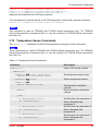
2.6.1 Numeric Parameters
Commands that require numeric parameters will accept all commonly used decimal
representations of numbers including optional signs, decimal points, and scientific notation.
Special values for numeric parameters such as MIN, MAX, and DEF may also be accepted. You
can also send engineering unit suffixes with numeric parameters (e.g., M, k, m, or u). If a
command accepts only certain specific values, the instrument will automatically round the input
numeric parameter to the accepted values.
Additionally numeric parameters can be programmed using binary, decimal, hexadecimal or
octal data formats for the parameter value (for a detailed description of numeric formats see
chapter 7.7.4 <NONDECIMAL NUMERIC PROGRAM DATA> of IEEE488.2-1992).
Example
The four commands program the Auxiliary Enable Register to the same value:
? STAT:AUX:ENAB 2081
Program the Auxiliary Enable Register with 2018 decimal.
?
STAT:AUX:ENAB #H821
Program the Auxiliary Enable Register with 821 hexadecimal.
?
STAT:AUX:ENAB #Q4041
Program the Auxiliary Enable Register with 4041 octal.
?
STAT:AUX:ENAB #B100000100001
Program the Auxiliary Enable Register with 100000100001 binary.
© 2012 Thorlabs
7
Series 4000 SCPI Programmers Reference Manual
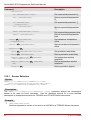
2.6.2 Discrete Parameters
Discrete parameters are used to program settings that have a limited number of values (like
CELSius, FAHRenheit or KELVin). They have a short form and a long form just like command
keywords. You can mix upper- and lower-case letters. Query responses will always return the
short form in all upper-case letters.
Example
The following command requires a discrete parameter for the temperature unit:
? UNIT:TEMPerature {C|CEL|CELSius|F|FAR|FAHRenheit|K|KELVin}
Discrete parameters may also have a default condition. In this manual the default conditions
are underlined.
2.6.3 Boolean Parameters
Boolean parameters represent a single binary condition that is either true or false. For a false
condition, the instrument will accept OFF or 0. For a true condition, the instrument will accept ON
or 1. When you query a boolean setting, the instrument will always return 0 or 1.
Boolean parameters may also have a default condition. In this manual the default conditions
are underlined.
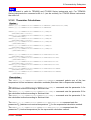
2.6.4 ASCII String Parameters
String parameters can contain virtually any set of ASCII characters. A string must begin and
end with matching quotes; either with a single quote or a double quote. You can include the
quote delimiter as part of the string by typing it twice without any characters in between.
8
© 2012 Thorlabs
3 Commands by Subsystem
3 Commands by Subsystem
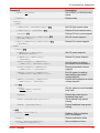
3.1 IEEE-488.2 Commands
The IEEE-488.2 standard defines a set of common commands that perform functions such as
reset, self-test, and status operations. Common commands always begin with an asterisk (*),
are three characters in length, and may include one or more parameters. The command
keyword is separated from the first parameter by a blank space. Use a semicolon (;) to
separate multiple commands. IEEE488.2 commands are device commands that are common
to all devices according to the IEEE488.2 standard. Most of the commands are described in
detail in this section. The following common commands associated with the status structure are
related to the STATus Subsystem Commands 62 section: *CLS,*ESE,*ESE?,*ESR?,*SRE,
*SRE?,*STB?
See also figure Status Structure
62
.
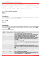
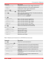
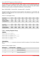
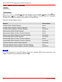
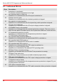
Table 1: IEEE-488.2 commands
Mnemonic
Name
Description
*CLS
13
Clear status
Clear all event registers and Error Queue
*ESE
13
<value> Event enable
Program the Standard Event Enable Register
command
*ESE?
13
Event enable
query
Read the Standard Event Enable Register
*ESR?
13
Event status
register query
Read and clear the Standard Event Register
*IDN?
10
Identification
query
Read the unit’s identification string
Operation
complete
command
Set the Operation Complete bit in the Standard Event
Register
Operation
complete query
Place a 1 into the output queue when all device
operations have been completed
*OPC
11
*OPC?
11
*RCL
11
<value> Recall command
*RST
10
Reset command
*SAV
11
<value> Save default
Return the unit to the user-saved setup
Return the unit to the *RST default condition
Initialize the content of save/recall registers
device setting
*SDS
11
<value> Save default
Initialize the content of save/recall registers
device setting
*SRE
12
<value> Service request
Program the Service Request Enable Register
enable command
*SRE?
12
Service request
enable query
*STB?
12
Status byte query Read the Status Byte Register
*TST?
11
Self-test query
Perform the unit’s self-test and return the result.
Wait-to-continue
command
Wait until all previous commands are executed
*WAI
12
© 2012 Thorlabs
Read the Service Request Enable Register
9
Series 4000 SCPI Programmers Reference Manual
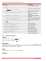
3.1.1 *IDN? - Identification Query
Syntax
*IDN?
Description
The identification query reads the instrument's identification code which contains four commaseparated fields. The first field is the manufacturer, the second field is the model code, the third
filed is the serial number, and the fourth field is the firmware revision code which contains two
(LDC4000) or three (TED4000, ITC4000) codes separated by slashes (/).
The query is sent in the following format:
THORLABS,MMM,SSS,X.X.X/Y.Y.Y/Z.Z.Z
Where:
MMM
is the model code
SSS
is the serial number
X.X.X
is the instrument firmware revision level
Y.Y.Y
is the firmware revision level of the front panel board
Z.Z.Z
is the firmware revision level of the temperature controller board (TED4000,
ITC4000 only)
Example
?
*IDN?
Query the ID code.
?
THORLABS,ITC4020,E12345678,1.4.0/2.0.3/1.6.0
Typical response.
3.1.2 *RST - Reset
Syntax
*RST
Description
When the *RST command is sent, the instrument performs the following operations:
Switches off the instrument's outputs.
Sets the direction of general purpose I/O1..4 to input.
Switches photodiode BIAS to OFF
10
© 2012 Thorlabs
3 Commands by Subsystem
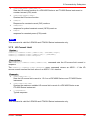
3.1.3 *SAV, *RCL, *SDS - Save/Recall Setup
Syntax
*SAV <value>
*RCL <value>
*SDS <value>
Description
Value: 0..7
Memory location 1 ... 8
Use the *SAV command to save the present instrument setup configuration in non-volatile
(state-) memory for later recall. The *RCL command is used to restore the instrument to the
saved setup configuration. Eight setup configurations can be saved and recalled.
Use the *SDS command to initialize the selected (state-) memory with factory default settings.
Your settings will be overwritten. See also chapter Memory Subsystem Commands 71 and
appendix Instrument Default Settings 85 .
Example
?
*SAV 1
Saves the present instrument setup configuration to memory location 2.
3.1.4 *TST? - Self Test
Syntax
*TST?
Description
Use this query command to perform the instrument self-test routine. The command places the
coded result in the output queue. A returned value of zero
(0) indicates that the test passed, other values indicate that the test failed and the error code is
placed into the instrument’s error queue.
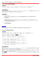
3.1.5 *OPC, *OPC? - Operation Complete
Syntax
*OPC
*OPC?
Description
When *OPC is sent, the OPC bit in the Standard Event Register will be set after all pending
command operations are complete. When *OPC? is sent, an ASCII 1 is placed in the output
queue after all pending command operations are complete.
© 2012 Thorlabs
11
Series 4000 SCPI Programmers Reference Manual
Typically, either one of these commands is sent after the INITiate command. The INITiate
command is used to take the instrument out of idle in order to perform measurements. While
operating within the trigger model layers, many sent commands will not execute. After all
programmed operations are completed, the instrument returns to the idle state at which time all
pending commands (including *OPC and/or *OPC?) are executed. When executing the OPC bit
in the status structure is set and/or an ASCII 1 is placed in the output queue.
3.1.6 *WAI - Wait To Continue
Syntax
*WAI
Description
The *WAI command is a no operation command for the instrument and thus, does not need to
be used. It is there for conformance to IEEE488.2.
3.1.7 *STB?
Syntax
*STB?
Description
The *STB? command queries the instrument's Status Byte Register. This is a read-only register
and the bits are not cleared when you read the register. See also figure Status Structure 62 .
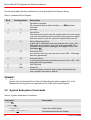
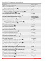
Table 2: Status Byte Register
Bit #
Decimal Value
0
1
AUX - Auxiliary Status Structure Summary Bit
One or more bits are set in the Auxiliary Event Register (bits
must be enabled, see Auxiliary Status Register Group 66 ).
1
2
MEAS - Measurement Status Structure Summary Bit
One or more bits are set in the Measurement Event Register
(bits must be enabled, see Measurement Status Register
Group 67 ).
2
4
EAV - Error Available Bit
One or more errors have been stored in the Error Queue. Use
the SYSTem:ERRor?[:NEXT] 15 command to read and delete
errors.
3
8
QUES - Questionable Data Structure Summary Bit
One or more bits are set in the Questionable Event Register
(bits must be enabled, see Questionable Data Register Group
68 ).
4
16
MAV - Message Available Bit
Data is available in the instrument's output buffer.
5
32
ESB - Standard Event Status Bit
One or more bits are set in the Standard Event Register (bits
must be enabled, see *ESE 13 command).
12
Mnemonic - Description
© 2012 Thorlabs
3 Commands by Subsystem
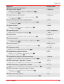
Bit #
Decimal Value
Mnemonic - Description
6
64
RQS/MSS - Request Service / Master Summary Status Bit
One or more bits are set in the Status Byte Register and may
generate a Request for Service (RQS). Bits must be enabled
using the *SRE 13 command.
7
128
OPER - Standard Operation Status Summary Bit
One or more bits are set in the Standard Operation Register
(bits must be enabled, see
STATus:OPERation:ENABle 69 command).
3.1.8 *SRE, *SRE?
Syntax
*SRE <value>
*SRE?
Description
The *SRE command enables bits in the enable register (Service Request Enable Register) for
the Status Byte Register Group. See table Status Byte Register 12 for a description of the bits.
Once enabled, the corresponding bits may generate a Request for Service (RQS) in the status
byte. This RQS event may generate a "call back" to your application as a type of asynchronous
interrupt.
3.1.9 *CLS
Syntax
*CLS
Description
The *CLS command clears the event registers in all register groups. This command also clears
the error queue.
3.1.10 *ESR?, *ESE, *ESE?
Syntax
*ESR?
*ESE <value>
*ESE?
Description
The *ESR? command queries the Standard Event Register. In order to be reported to the
Status Byte Register, the corresponding bits in the event register must be enabled using the
*ESE command.
The *ESE command enables bits in the enable register (Standard Event Status Enable
Register) for the Standard Event Register Group. The selected bits are then reported to bit 5 of
the Status Byte Register.
See also chapter Status Subsystem
© 2012 Thorlabs
62
and figure Status Structure
62
.
13
Series 4000 SCPI Programmers Reference Manual
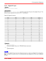
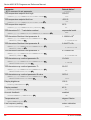
The following table lists the bit definitions for the Standard Event Register Group.
Table 3: Standard Event Register
Bit #
Decimal Value
0
1
Description
Operation Complete
All commands prior to and including *OPC
executed
11
have been
1
2
not used
2
4
Query Error
The instrument tried to read the output buffer but it was empty
or a new command line was received before a previous query
has been read or both the input and output buffers are full.
3
8
Device Dependent Error
A self-test or calibration error occurred (an error in the -300...399 range or any positive error has been generated). For a
complete listing of error messages, see chapter SCPI Error
Messages 78 .
4
16
Execution Error
An execution error occurred (an error in the -200...-299 range
has been generated).
5
32
Command Error
A command syntax error occurred (an error in the -100...-199
range has been generated).
6
64
User Request
7
128
Power On
Power has been turned off and on since the last time the
event register was read or cleared.
Example
?
*ESE 4
Sets bit 2 of the Standard Event Status Enable Register which enables bit 2 of the
Standard Event Register to be reported to bit 5 of the Status Byte Register.
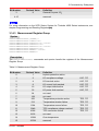
3.2 System Subsystem Commands
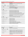
Table 4: System Subsystem Commands
Command
SYSTem
21
:BEEPer
14
Description
15
[:IMMediate]
Issues an audible signal
:STATE {ON|1|OFF|0}
Activates/deactivates the beeper
© 2012 Thorlabs
3 Commands by Subsystem
Command
Description
:STATe?
:ERRor
Returns the state of the beeper
15
[:NEXT]?
:LFRequency
Returns the latest <error code>, "Message"
16
{50|60|AUTO}
:ACTual?
:LFRequency?
:VERSion?
Sets the line frequency to fixed 50/60Hz or
auto detect
Returns the used line frequency
16
16
Returns the line frequency setting
Returns the level of SCPI standard (1999.0)
3.2.1 Beeper
Syntax
SYSTem:BEEPer[:IMMediate]
SYSTem:BEEPer:STATe {ON|1|OFF|0}
SYSTem:BEEPer:STATe?
Description
The SYSTem:BEEPer[:IMMediate] issues an audible signal.
The SYSTem:BEEPer:STATe command activates or deactivates the beeper.
Example
?
SYST:BEEP
The instrument will issue an audible signal.
?
SYST:BEEP:STAT?
Queries the state of the beeper activation.
?
1
Response for beeper activated. The response is ASCII 1 if the beeper is activated or an
ASCII 0 if the beeper is deactivated.
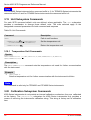
3.2.2 Error Query
Syntax
SYSTem:ERRor[:NEXT]?
Description
The SYSTem:ERRor[:NEXT]? command queries the instrument's error queue. This is a queryonly command. For a detailed list of possible error codes see chapter SCPI Error Messages 78 .
Example
?
SYST:ERR?
Query the error queue.
?
+0,"No error"
Typical response.
© 2012 Thorlabs
15
Series 4000 SCPI Programmers Reference Manual
3.2.3 Line Frequency
Syntax
SYSTem:LFRequency {50|60|AUTO}
SYSTem:LFRequency:ACTual?
SYSTem:LFRequency?
Description
The SYSTem:LFRequency sets the line frequency to use for signal filtering to the given value or
to automatic detection.
With the SYSTem:LFRequency:ACTual? query the actual used value can be retrieved.
The SYSTem:LFRequency? query returns the line frequency setting.
Example
?
SYST:LFR 50
Sets the line frequency setting to 50Hz.
?
SYST:LFR:ACT?
Queries the actual used line frequency.
?
60
Typical response.
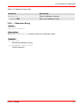
3.2.4 SCPI Version Query
Syntax
SYSTem:VERSion?
Description
The SYSTem:VERSion? command queries the level of the SCPI standard implemented. This is
a query–only command.
Example
?
SYST:VERS?
Query the SCPI version.
?
1999.0
Typical response.
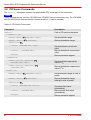
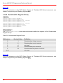
3.3 Measurement Commands
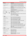
Table 5: Measurement Commands for a TED4000 Series Instrument
Command
Description
ABORt
Aborts the current measurement
21
CONFigure[:SCALar]
16
21
[:TEMPerature]
Configures instrument for temperature measurement
:CURRent[1][:DC]
Configures instrument for TEC current measurement
© 2012 Thorlabs
3 Commands by Subsystem
Command
Description
:VOLTage[1][:DC]
Configures instrument for TEC voltage measurement
:POWer[1]
Configures instrument for TEC power measurement
:TSENsor
Configures for sensor signal measurement
CONFigure?
Returns the current configuration
21
INITiate[:IMMediate]
FETCh?
FETCh
23
Starts measurement
Returns the last measurement data. The data returned is the
data configured with the last
CONFigure[:SCALar] or the last
MEASure[:SCALar] command
23
23
:TEMPerature?
Returns the last measured temperature
:CURRent[1][:DC]?
Returns the last measured TEC current
:VOLTage[1][:DC]?
Returns the last measured TEC voltage
:POWer[1]?
Returns the last measured TEC power
:TSENsor?
Returns the last measured sensor signal
READ?
Starts new measurement and returns data
25
MEASure[:SCALar]
25
[:TEMPerature]?
Measures temperature
:CURRent[1][:DC]?
Measures TEC current
:VOLTage[1][:DC]?
Measures TEC voltage
:POWer[1]?
Measures TEC power
:TSENsor?
Measures sensor signal
Table 6: Measurement Commands for a LDC4000 Series Instrument
Command
Description
ABORt
Aborts the current measurement
21
CONFigure[:SCALar]
21
[:CURRent][1][:DC]
Configures instrument for LD current measurement
:VOLTage[1][:DC]
Configures instrument for LD voltage measurement
:CURRent2[:DC]
Configures instrument for PD current measurement
:POWer2
Configures instrument for power measurement via
photodiode
:VOLTage2[:DC]
Configures instrument for thermopile/power meter voltage
measurement
:POWer3
Configures instrument for power measurement via
thermopile/power meter
© 2012 Thorlabs
17
Series 4000 SCPI Programmers Reference Manual
Command
Description
:POWer[1]
CONFigure?
Configures instrument for LD electrical input power
measurement
Returns the current configuration
21
INITiate[:IMMediate]
FETCh?
FETCh
23
Starts measurement
Returns the last measurement data. The data returned is the
data configured with the last
CONFigure[:SCALar] or the last
MEASure[:SCALar] command
23
23
:CURRent[1][:DC]?
Returns the last measured LD current
:VOLTage[1][:DC]?
Returns the last measured LD voltage
:CURRent2[:DC]?
Returns the last measured PD current
:POWer2?
Returns the last measured optical power (via PD)
:VOLTage2[:DC]?
Returns the last measured thermopile/power meter voltage
:POWer3?
Returns the last measured optical power (via thermopile/
power meter)
:POWer[1]?
Returns the last measured LD input electrical power
READ?
Starts new measurement and returns data
25
MEASure[:SCALar]
25
[:CURRent][1][:DC]?
Measures LD current
:VOLTage[1][:DC]?
Measures LD voltage
:CURRent2[:DC]?
Measures PD current
:POWer2?
Measures LD power via PD
:VOLTage2[:DC]?
Measures thermopile/power meter voltage
:POWer3?
Measures LD power via thermopile/power meter
:POWer[1]?
Measures LD electrical input power
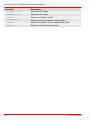
Table 7: Measurement Commands for a ITC4000 Series Instrument
Command
Description
ABORt
Aborts the current measurement
21
CONFigure[:SCALar]
18
21
:TEMPerature
Configures instrument for temperature measurement
:CURRent3[:DC]
Configures instrument for TEC current measurement
:VOLTage3[:DC]
Configures instrument for TEC voltage measurement
:POWer4
Configures instrument for TEC power measurement
:TSENsor
Configures instrument for temperature sensor signal
measurement
© 2012 Thorlabs
3 Commands by Subsystem
Command
Description
[:CURRent][1][:DC]
Configures instrument for LD current measurement
:VOLTage[1][:DC]
Configures instrument for LD voltage measurement
:CURRent2[:DC]
Configures instrument for PD current measurement
:POWer2
Configures instrument for for power measurement via
photodiode
:VOLTage2[:DC]
Configures instrument for thermopile/power meter voltage
measurement
:POWer3?
Configures instrument for power measurement via
thermopile/power meter
:POWer[1]?
Configures instrument for LD electrical input power
measurement
CONFigure?
Returns the current configuration
21
INITiate[:IMMediate]
FETCh?
FETCh
23
Starts measurement
Returns the last measurement data. The data returned is the
data configured with the last
CONFigure[:SCALar] or the last
MEASure[:SCALar] command
23
23
:TEMPerature?
Returns the last measured temperature
:CURRent3[:DC]?
Returns the last measured TEC current
:VOLTage3[:DC]?
Returns the last measured TEC voltage
:POWer4?
Returns the last measured TEC power
:TSENsor?
Returns the last measured temperature sensor signal
:CURRent[1][:DC]?
Returns the last measured LD current
:VOLTage[1][:DC]?
Returns the last measured LD voltage
:CURRent2[:DC]?
Returns the last measured PD current
:POWer2?
Returns the last measured optical power (via PD)
:VOLTage2[:DC]?
Returns the last measured thermopile/power meter voltage
:POWer3?
Returns the last measured optical power (via thermopile/
power meter)
:POWer[1]?
Returns the last measured LD input electrical power
READ?
Starts new measurement and returns data
25
MEASure[:SCALar]
25
:TEMPerature?
Measures temperature
:CURRent3[:DC]?
Measures TEC current
:VOLTage3[:DC]?
Measures TEC voltage
:POWer4?
Measures TEC power
:TSENsor?
Measures temperature sensor signal
:CURRent[1][:DC]?
Measures LD current
© 2012 Thorlabs
19
Series 4000 SCPI Programmers Reference Manual
Command
20
Description
:VOLTage[1][:DC]?
Measures LD voltage
:CURRent2[:DC]?
Measures PD current
:POWer2?
Measures LD power via PD
:VOLTage2[:DC]?
Measures thermopile/power meter voltage
:POWer3?
Measures LD power via thermopile/power meter
:POWer[1]?
Measures LD electrical input power
© 2012 Thorlabs
3 Commands by Subsystem
3.3.1 Abort Measurement in Progres
Syntax
ABORt
Description
This command aborts a measurement in progress.
Remarks
This command aborts a measurement a measurement in progress and stops, returning the
instrument to the idle state.
Example
?
ABOR
Abort the measurement in progress.
3.3.2 Configuring a Measurement
Syntax
For TED4000 Series instruments:
CONFigure[:SCALar][:TEMPerature]
CONFigure[:SCALar]:CURRent[1][:DC]
CONFigure[:SCALar]:VOLTage[1][:DC]
CONFigure[:SCALar]:POWer[1]
CONFigure[:SCALar]:TSENsor
CONFigure?
For LDC4000 Series instruments:
CONFigure[:SCALar][:CURRent][1][:DC]
CONFigure[:SCALar]:VOLTage[1][:DC]
CONFigure[:SCALar]:CURRent2[:DC]
CONFigure[:SCALar]:POWer2
CONFigure[:SCALar]:VOLTage2[:DC]
CONFigure[:SCALar]:POWer3
CONFigure[:SCALar]:POWer[1]
CONFigure?
For ITC4000 Series instruments:
CONFigure[:SCALar]:TEMPerature
CONFigure[:SCALar]:CURRent3[:DC]
CONFigure[:SCALar]:VOLTage3[:DC]
CONFigure[:SCALar]:POWer4
CONFigure[:SCALar]:TSENsor
CONFigure[:SCALar][:CURRent][1][:DC]
CONFigure[:SCALar]:VOLTage[1][:DC]
CONFigure[:SCALar]:CURRent2[:DC]
CONFigure[:SCALar]:POWer2
CONFigure[:SCALar]:VOLTage2[:DC]
CONFigure[:SCALar]:POWer3
CONFigure[:SCALar]:POWer[1]
CONFigure?
© 2012 Thorlabs
21
Series 4000 SCPI Programmers Reference Manual
Description
Configures the instrument to measure the selected value. The CONFigure command does not
perform the measurement. Use the INITiate or READ? command to take the configured
measurement. The configuration query returns the current measurement configuration.
Example
The following program segment configures a TED4000 Series instrument for temperature
measurements and performs one measurement with the READ? command.
? CONF:TEMP
Configure the instrument for temperature measurement.
?
READ?
Perform a measurement and send the reading to the output buffer.
?
2.500000E+01
Typical response.
Example
The following program segment configures a TED4000 Series instrument for temperature
measurements and performs one measurement with the INITiate[:IMMediate] and FETCh?
command sequence.
? CONF:TEMP
Configure the instrument for temperature measurement.
?
INIT
Perform the measurement and store reading in memory.
?
FETC?
Transfer reading from memory to instrument's output buffer.
?
2.500000E+01
Typical response.
Example
?
CONF?
Query the current measurement configuration.
?
TEMP
Typical response.
Example
The following program segment configures a LDC4000 Series instrument for thermopile/power
meter voltage measurements and performs one measurement with the INITiate[:
IMMediate] and FETCh? command sequence.
? CONF:VOLT2
Configure the instrument for thermopile/power meter voltage measurement.
?
INIT
Perform the measurement and store reading in memory.
22
© 2012 Thorlabs
3 Commands by Subsystem
?
FETC?
Transfer reading from memory to instrument's output buffer.
?
3.770000E-01
Typical response.
Example
The following program segment configures a ITC4000 Series instrument for TEC current
measurement and performs one measurement with the READ? command.
? CONF:CURR3
Configure the instrument for TEC current measurement.
?
READ?
Perform a measurement and send the reading to the output buffer.
?
6.532000E+00
Typical response.
3.3.3 Initiating a Measurement
Syntax
INITiate[:IMMediate]
Description
This command performs a previously configured measurement, and stores the reading in
memory.
Example
The following program segment configures a TED4000 / ITC4000 Series Instrument for
temperature measurements and performs one measurement.
? CONF:TEMP
Configure the instrument for temperature measurement.
?
INIT
Perform the measurement and store reading in memory.
?
FETC?
Transfer reading from memory to instrument's output buffer.
?
2.500000E+01
Typical response.
3.3.4 Fetch a Measurement
Syntax
For TED4000 Series instruments:
FETCh?
FETCh:TEMPerature?
© 2012 Thorlabs
23
Series 4000 SCPI Programmers Reference Manual
FETCh:CURRent[1][:DC]?
FETCh:VOLTage[1][:DC]?
FETCh:POWer[1]?
FETCh:TSENsor?
For LDC4000 Series instruments:
FETCh?
FETCh:CURRent[1][:DC]?
FETCh:VOLTage[1][:DC]?
FETCh:CURRent2[:DC]?
FETCh:POWer2?
FETCh:VOLTage2[:DC]?
FETCh:POWer3?
FETCh:POWer[1]?
For ITC4000 Series instruments:
FETCh?
FETCh:TEMPerature?
FETCh:CURRent3[:DC]?
FETCh:VOLTage3[:DC]?
FETCh:POWer4?
FETCh:TSENsor?
FETCh:CURRent[1][:DC]?
FETCh:VOLTage[1][:DC]?
FETCh:CURRent2[:DC]?
FETCh:POWer2?
FETCh:VOLTage2[:DC]?
FETCh:POWer3?
FETCh:POWer[1]?
Description
This command transfers readings from memory to the instrument's output buffer where you can
read them into your computer. The readings are not erased from memory when you read them.
You can send the command multiple times to retrieve the same data. With the FETCh?
command the last configured measurement will be transferred to the instruments output buffer.
With FETCh:XXX? the value of the last measurement of XXX will be transferred to the
instruments output buffer.
Example
?
FETC?
Query last measurement.
?
2.500000E+01
Typical response.
Example
?
FETC:POW2?
Query last measurement of optical power via photodiode of an ITC4000 Series
instrument.
24
© 2012 Thorlabs
3 Commands by Subsystem
?
4.520000E-03
Typical response.
3.3.5 Read Measurement Data
Syntax
READ?
Description
The READ? command performs a previously configured measurement, and then sends the
reading to the instrument output buffer. It has the same effect as INITiate[:IMMediate]
followed by the FETCh? command.
Example
The following program segment configures a TED4000 / ITC4000 Series instrument for
temperature measurements and performs one measurement.
? CONF:TEMP
Configure the instrument for temperature measurement.
?
READ?
Perform a measurement and send the reading to the output buffer.
?
2.500000E+01
Typical response.
3.3.6 Simple Measurement
Syntax
For TED4000 Series instruments:
MEASure[:SCALar][:TEMPerature]?
MEASure[:SCALar][:CURRent][1][:DC]?
MEASure[:SCALar]:VOLTage[1][:DC]?
MEASure[:SCALar]:POWer[1]?
MEASure[:SCALar]:TSENsor?
For LDC4000 Series instruments:
MEASure[:SCALar][:CURRent][1][:DC]?
MEASure[:SCALar]:VOLTage[1][:DC]?
MEASure[:SCALar]:CURRent2[:DC]?
MEASure[:SCALar]:POWer2?
MEASure[:SCALar]:VOLTage2[:DC]?
MEASure[:SCALar]:POWer3?
MEASure[:SCALar]:POWer[1]?
For ITC4000 Series instruments:
MEASure[:SCALar]:TEMPerature?
MEASure[:SCALar]:CURRent3[:DC]?
MEASure[:SCALar]:VOLTage3[:DC]?
MEASure[:SCALar]:POWer4?
© 2012 Thorlabs
25
Series 4000 SCPI Programmers Reference Manual
MEASure[:SCALar]:TSENsor?
MEASure[:SCALar][:CURRent[1]][:DC]?
MEASure[:SCALar]:VOLTage[1][:DC]?
MEASure[:SCALar]:CURRent2[:DC]?
MEASure[:SCALar]:POWer2?
MEASure[:SCALar]:VOLTage2[:DC]?
MEASure[:SCALar]:POWer3?
MEASure[:SCALar]:POWer[1]?
Description
The MEASure? command provides the easiest way to program the instrument for
measurements. However, this command does not offer much flexibility. The results are sent
directly to the instrument's output buffer. Sending MEASure? is functionally the same as
sending CONFigure followed immediately by a READ? command.
Example
?
MEAS:TEMP?
Query temperature of a TED4000 / ITC4000 Series instrument.
?
2.500000E+01
Typical response.
3.4 LD Output Commands
The OUTPut[1] subsystem controls the LD output of the instrument.
Note
These commands are valid for LDC4000 and ITC4000 Series instruments only. For LDC4000
and ITC4000 Series instruments the command suffix is 1 (can be omitted).
Table 8: LD Output Commands
Command
Description
OUTPut[1]
Path to LD output
[:STATe]
:DELay
27
27
:POLarity
{OFF|ON|0|1}
{MIN|MAX|DEF|<seconds>}
{NORMal|CG|INVerted|AG}
28
Set output state
Set switch-on delay
Set output polarity
:PROTection
:VOLTage
[:LEVel]
{MIN|MAX|DEF|<volts>}
28
[:LEVel]?
28
:TRIPped?
30
{MIN|MAX|DEF}
Set output protection voltage
Return output protection voltage
Return voltage protection tripped
:EXTernal
[:MODE]
29
:TRIPped?
{OFF|PROTection|ENABle}
30
Set external protection mode
Return external protection tripped
:INTernal
26
© 2012 Thorlabs
3 Commands by Subsystem
Command
Description
[:MODE]
29
:TRIPped?
{OFF|PROTection|ENABle}
Set internal protection mode
30
Return internal protection tripped
30
Return interlock protection tripped
30
Return front panel key switch
protection tripped
30
Return over temperature protection
tripped
:INTLock
:TRIPped?
:KEYLock
:TRIPped?
:OTEMp
:TRIPped?
3.4.1 Output State
Syntax
OUTPut[1][:STATe] {OFF|0|ON|1}
OUTPut[1][:STATe]?
Description
The OUTPut[1][:STATe] command switches the instrument's LD output on/off.
Example
?
OUTP ON
Switches the LD output on.
?
OUTP?
Queries the state of the LD output.
?
1
The response is ASCII 1 if the output is switched on or an ASCII 0 if the output is off.
Note
This command is valid for LDC4000 and ITC4000 Series instruments only.
Note
The *RST
10
command switches the output off.
3.4.2 Switch-On Delay
Syntax
OUTPut[1]:DELay {MIN|MAX|DEF|<seconds>}
OUTPut[1]:DELay? [{MIN|MAX|DEF}]
Description
© 2012 Thorlabs
27
Series 4000 SCPI Programmers Reference Manual
The OUTPut[1]:DELay sets the output switch-on delay of the LD output.
Example
?
OUTP:DEL 3
Sets the LD output switch-on delay to 3 seconds.
Note
This command is valid for LDC4000 and ITC4000 Series instruments only.
3.4.3 Polarity
Syntax
OUTPut[1]:POLarity {NORMal|CG|INVerted|AG}
OUTPut[1]:POLarity?
Description
The OUTPut[1]:POLarity command sets the LD output polarity to cathode ground (NORMal or
CG) or anode ground (INVerted or AG). The parameters NORMal and INVerted are for SCPI
conformance.
Example
?
OUTP:POL CG
Sets the LD output polarity to cathode ground.
?
OUTP:POL?
Queries the LD output polarity.
?
CG
The response is either CG or AG.
Note
This command is valid for LDC4000 and ITC4000 Series instruments only.
3.4.4 Protection Voltage
Syntax
OUTPut[1]:PROTection:VOLTage[:LEVel] {MIN|MAX|DEF|<volts>}
OUTPut[1]:PROTection:VOLTage[:LEVel]? [{MIN|MAX|DEF}]
Description
The OUTPut[1]:PROTection:VOLTage[:LEVel] command sets the output voltage protection
(compliance voltage) threshold. If this threshold is reached the output switches off.
Example
?
OUTP:PROT:VOLT 8.0
Sets the LD output protection voltage to 8V.
28
© 2012 Thorlabs
3 Commands by Subsystem
?
OUTP:PROT:VOLT? MAX
Queries the maximum settable LD output protection voltage.
?
1.000000E+01
Typical response.
Note
This command is valid for LDC4000 and ITC4000 Series instruments only.
3.4.5 Temperature Protection Mode
Syntax
OUTPut[1]:PROTection:INTernal[:MODE] {OFF|PROTection|ENABle}
OUTPut[1]:PROTection:INTernal[:MODE]?
Description
The OUTPut[1]:PROTection:INTernal[:MODE] command sets the function of the internal
temperature protection circuit.
Parameter
Description
OFF
Temperature protection is disabled and has no effect on the LD output
PROTection
Acts as protection.
If the temperature is out of bounds the LD output is switched off
ENABle
Acts as enable.
If the temperature is out of bounds the LD output is disabled temporarily.
Example
?
OUTP:PROT:INT ENAB
Sets the temperature protection mode to output-enable mode.
Note
This command is valid for ITC4000 Series instruments only.
See also Temperature Protection
58
for further details.
3.4.6 LD-ENABLE Input Mode
Syntax
OUTPut[1]:PROTection:EXTernal[:MODE] {OFF|PROTection|ENABle}
OUTPut[1]:PROTection:EXTernal[:MODE]?
Description
The OUTPut[1]:PROTection:EXTernal[:MODE] command sets the function of the rear panel
LD-ENABLE input.
© 2012 Thorlabs
29
Series 4000 SCPI Programmers Reference Manual
Parameter
Description
OFF
The LD-ENABLE input is ignored and has no effect
PROTection
Acts as protection input (inhibit functionality).
A TTL low level switches the LD output off.
ENABle
Acts as enable input.
A TTL low level disables the LD output temporarily.
Example
?
OUTP:PROT:EXT ENAB
Sets the LD-ENABLE input mode to output-enable mode.
Note
This command is valid for LDC4000 and ITC4000 Series instruments only.
3.4.7 Protection Queries
Syntax
OUTPut[1]:PROTection:VOLTage:TRIPped?
OUTPut[1]:PROTection:EXTernal:TRIPped?
OUTPut[1]:PROTection:INTernal:TRIPped?
OUTPut[1]:PROTection:INTLock:TRIPped?
OUTPut[1]:PROTection:KEYLock:TRIPped?
OUTPut[1]:PROTection:OTEMp:TRIPped?
Description
The OUTPut[1]:PROTection:VOLTage:TRIPped? query command returns 1 if the LD output
protection voltage was reached.
The OUTPut[1]:PROTection:EXTernal:TRIPped? query command returns 1 if the LDENABLE input has a TTL low level.
The OUTPut[1]:PROTection:INTernal:TRIPped? query command returns 1 if the
temperature window protection is currently active. This command is valid for ITC4000
instruments only.
The OUTPut[1]:PROTection:INTLock:TRIPped? query command returns 1 if the interlock
circuit is open.
The OUTPut[1]:PROTection:KEYLock:TRIPped? query command returns 1 if the front panel
key switch is in the lock position.
The OUTPut[1]:PROTection:OTEMp:TRIPped? query command returns 1 if the instrument's
internal temperature is too high.
Example
30
© 2012 Thorlabs
3 Commands by Subsystem
?
OUTP:PROT:KEYL:TRIP?
Queries the front panel key switch.
?
0
Typical response.
Note
These commands are valid for LDC4000 and ITC4000 only.
3.5 PD Input Commands
The INPut[1] subsystem controls the PD input of the instrument.
Note
These commands are valid for LDC4000 and ITC4000 Series instruments only. For LDC4000
and ITC4000 Series instruments the command suffix is 1 (can be omitted).
Table 9: PD Input Commands
Command
Description
INPut[1]
Path to PD input
:POLarity
31
:POLarity?
{NORMal|CG|INVerted|AG}
Return input state
31
:BIAS[:STATe]
Set input state
32
:BIAS[:STATe]?
Switch PD-Bias on or off
{OFF|0|ON|1}
Return PD-Bias state
32
:BIAS:VOLTage[:DC] 32
{MIN|MAX|DEF|<volts>}
Set PD-Bias voltage level
:BIAS:VOLTage[:DC]?
Return PD-Bias voltage
:ROUTe[:TERMinals]
32
33
:ROUTe[:TERMinals]?
[{MIN|MAX|DEF}]
Set PD-input routing
{DSUB|BNC}
Return PD-input routing
33
See also chapter PD Sense Commands
42
.
3.5.1 Polarity
Syntax
INPut[1]:POLarity {NORMal|CG|INVerted|AG}
INPut[1]:POLarity?
Description
The INPut[1]:POLarity command sets the PD input polarity to cathode ground (NORMal or
CG) or anode ground (INVerted or AG). The parameters NORMal and INVerted are for SCPI
conformance.
© 2012 Thorlabs
31
Series 4000 SCPI Programmers Reference Manual
Example
?
INP:POL CG
Sets the PD input polarity to cathode ground.
?
INP:POL?
Queries the PD input polarity.
?
CG
The response is either CG or AG.
Note
This command is valid for LDC4000 and ITC4000 Series instruments only.
3.5.2 BIAS State
Syntax
INPut[1]:BIAS[:STATe] {OFF|0|ON|1}
INPut[1]:BIAS[:STATe]?
Description
The INPut[1]:BIAS[:STATe] command switches the instrument's PD input BIAS on/off.
Example
?
INP:BIAS ON
Switches the PD input BIAS on.
?
INP:BIAS?
Queries the state of the PD input BIAS.
?
1
The response is ASCII 1 if the BIAS is switched on or an ASCII 0 if the BIAS is off.
Note
This command is valid for LDC4000 and ITC4000 Series instruments only.
Note
The *RST
10
command switches the BIAS off.
3.5.3 BIAS Voltage
Syntax
INPut[1]:BIAS:VOLTage[:DC] {MIN|MAX|DEF|<volts>}
INPut[1]:BIAS:VOLTage[:DC]? [{MIN|MAX|DEF}]
Description
The INPut[1]:BIAS:VOLTage[:DC] command sets the PD input BIAS voltage.
Example
32
© 2012 Thorlabs
3 Commands by Subsystem
?
INP:BIAS:VOLT 800mV
Sets the PD input BIAS voltage to 0.8V.
?
INP:BIAS:VOLT? MAX
Queries the maximum settable PD input BIAS voltage.
?
5.000000E+01
Typical response.
Note
This command is valid for LDC4000 and ITC4000 Series instruments only.
3.5.4 Input Routing
Syntax
INPut[1]:ROUTe[:TERMinals] {DSUB|BNC}
INPut[1]:ROUTe[:TERMinals]?
Description
The INPut[1]:ROUTe[:TERMinals] command sets the path for the PD input routing to either
the rear panel LASER OUTPUT D-SUB connector or the rear panel BNC connector.
Example
?
INP:ROUT BNC
Sets the path for the PD input to the rear panel BNC connector.
?
INP:ROUT?
Queries the path for the PD input routing.
?
BNC
The answer is either DSUB or BNC.
Note
This command is valid for LDC4000 and ITC4000 Series instruments only.
3.6 Thermopile/Power Meter Input Commands
The INPut2 subsystem controls the thermopile/power meter input of the instrument.
Note
These commands are valid for LDC4000 and ITC4000 Series instruments only.
Table 10: Thermopile/Power Meter Input Commands
Command
Description
INPut[2]
Path to PD input
© 2012 Thorlabs
33
Series 4000 SCPI Programmers Reference Manual
Command
Description
:ROUTe[:TERMinals]
34
:ROUTe[:TERMinals]?
{DSUB|BNC}
34
Set thermopile/power meter input routing
Return thermopile/power meter input routing
See also chapter Thermopile/Power Meter Sense Commands
45
.
3.6.1 Input Routing
Syntax
INPut2:ROUTe[:TERMinals] {DSUB|BNC}
INPut2:ROUTe[:TERMinals]?
Description
The INPut2:ROUTe[:TERMinals] command sets the path for the thermopile/power meter
input routing either to the rear panel LASER OUTPUT D-SUB connector or to the rear panel
BNC connector.
Example
?
INP2:ROUT BNC
Sets the path for the thermopile/power meter input to the rear panel BNC connector.
?
INP2:ROUT?
Queries the path for the thermopile/power meter input routing.
?
BNC
The answer is either DSUB or BNC.
Note
This command is valid for LDC4000 and ITC4000 Series instruments only.
3.7 LD Source Commands
The SOURce[1] subsystem controls the LD source part of the instrument.
Note
These commands are valid for LDC4000 and ITC4000 Series instruments only.
Table 11: LD Source Commands
Command
Description
SOURce[1]
Path to LD source function
34
:FUNCtion
36
[:MODE]
51
[:MODE]
51 ?
{CURRent|POWer}
Set LD driver source function
Return LD driver source
function
© 2012 Thorlabs
3 Commands by Subsystem
Command
Description
[:SHAPe] {DC|PULSE}
Set CW(DC) or QCW(PULSe)
mode
[:SHAPe]?
Return mode
:CURRent
:LIMit
[:AMPLitude] {MIN|MAX|<amps>}
[:AMPLitude]? [{MIN|MAX}}
:TRIPped?
Set LD limit current value
37
Return LD limit current value
37
Return LD limit current tripped
37
[:LEVel][:IMMediate][:AMPLitude]
{MIN|MAX|<amps>}
38
[:LEVel][:IMMediate][:AMPLitude]?
[{MIN|MAX}]
37
Set LD current setpoint
Return LD current setpoint
:POWer
[:LEVel]
[:IMMediate][:AMPLitude]
{MIN|MAX|<watts>}
Set LD power setpoint
[:IMMediate][:AMPLitude]?
[{MIN|MAX}]
Return LD power setpoint
:DIODe[:CURRent][:IMMediate]
[:AMPLitude] {MIN|MAX|<amps>}
Set LD power via setting
photodiode current setpoint
:DIODe[:CURRent][:IMMediate]
[:AMPLitude]? [{MIN|MAX}]
Return photodiode current
setpoint
:PMETer[:VOLTage][:IMMediate]
[:AMPLitude] {MIN|MAX|<volts>}
Set LD power via setting
thermopile/power meter
voltage setpoint
:PMETer[:VOLTage][:IMMediate]
[:AMPLitude]? [{MIN|MAX}]
Return thermopile/power meter
voltage setpoint
:ALC
:AM
38
39
:SOURce
{DIODe|PMETer|PDIode|
THERmopile}
Set the power source feedback
loop input
:SOURce?
Return the power source
feedback loop input
:SPEed {MIN|MAX|DEF|<percent>}
Set feedback loop speed
setting
:SPEed? [{MIN|MAX|DEF}]
Return feedback loop speed
setting
40
[:STATe] {OFF|0|ON|1}
Enables (ON) or disables
(OFF) modulation
[:STATe]?
Return modulation state
:SOURce {INTernal|EXTernal}
[,{INTernal|EXTernal}]
Set modulation source
© 2012 Thorlabs
35
Series 4000 SCPI Programmers Reference Manual
Command
:SOURce?
Description
Return modulation source
:INTernal
:SHAPe
{SINusoid|SQUare|TRIangle}
Set internal modulation shape
:SHAPe?
Return internal modulation
shape
:FREQuency {MIN|MAX|DEF|<hertz>}
Set internal modulation
frequency
:FREQuency? [{MIN|MAX|DEF}]
Return internal modulation
frequency
[:DEPTh] {MIN|MAX|DEF|<percent>}
Set internal modulation depth
[:DEPTh]? [{MIN|MAX|DEF}]
Return internal modulation
depth
:PULSe
41
:PERiod {MIN|MAX|DEF|<secs>}
Set pulse period
:PERiod? [{MIN|MAX|DEF}]
Return pulse period
:WIDTh {MIN|MAX|DEF|<secs>}
Set pulse width
:WIDTh? [{MIN|MAX|DEFault}]
Return pulse width
:DCYCle {MIN|MAX|DEF|<percent>}
Set pulse duty cycle
:DCYCle? [{MIN|MAX|DEF}]
Return pulse duty cycle
:HOLD {WIDTh|DCYCle}
Set parameter to hold
:HOLD?
Return parameter to hold
3.7.1 LD Source Function
Syntax
SOURce[1]:FUNCtion:MODE {CURRent|POWer}
SOURce[1]:FUNCtion:MODE?
SOURce[1]:FUNCtion[:SHAPe] {DC|PULSe}
SOURce[1]:FUNCtion[:SHAPe]?
Description
The SOURce[1]:FUNCtion:MODE and SOURce[1]:FUNCtion[:SHAPe] commands set the
instrument's LD source function to constant current (CW) mode or to pulsed constant current
(QCW) mode or to constant power (CW) mode.
Note
The combination POWer and PULSe is not available.
Example
36
© 2012 Thorlabs
3 Commands by Subsystem
?
SOUR:FUNC:MODE CURR;SHAP DC
Sets the LD source function of a LDC4000 Series or an ITC4000 Series instrument to
constant current (CW) mode.
?
SOUR:FUNC:MODE?;SHAP?
Queries the LD source function.
?
CURR;DC
Response for constant current (CW) mode or
?
CURR;PULS
response for pulsed constant current (QCW) mode or
?
POW;DC
response for constant power (CW) mode.
Note
This command is valid for LDC4000 and ITC4000 Series instruments only.
3.7.2 LD Current Limit
Syntax
SOURce[1]:CURRent:LIMit[:AMPLitude] {MIN|MAX|<amps>}
SOURce[1]:CURRent:LIMit[:AMPLitude]? [{MIN|MAX}]
SOURce[1]:CURRent:LIMit:TRIPped?
Description
The SOURce[1]:CURRent:LIMit[:AMPLitude] command sets the LD source limit current in
amperes.
The SOURce[1]:CURRent:LIMit:TRIPped? query command returns an ASCII 1 if the LD
source current reached the limit value or an ASCII 0 if it’s inactive.
Example
?
SOUR:CURR:LIM 1.5
Sets the LD source limit current to 1.5 A on a LDC4000 Series or an ITC4000 Series
instrument.
?
SOUR:CURR:LIM? MAX
Queries the maximum settable LD source limit current of a LDC4000 Series or an
ITC4000 Series instrument.
?
1.500000E+01
Typical response.
Note
This command is valid for LDC4000 and ITC4000 Series instruments only.
© 2012 Thorlabs
37
Series 4000 SCPI Programmers Reference Manual
3.7.3 LD Current Setpoint
Syntax
SOURce[1]:CURRent[:LEVel][:IMMediate][:AMPLitude] {MIN|MAX|<amps>}
SOURce[1]:CURRent[:LEVel][:IMMediate][:AMPLitude]? [{MIN|MAX}]
Description
The SOURce[1]:CURRent[:LEVel][:IMMediate][:AMPLitude] command sets the LD
current setpoint in amperes in current source modes.
Example
?
SOUR:CURR 1.0
Sets the LD source current to 1.0 A on a LDC4000 Series or an ITC4000 Series
instrument.
?
SOUR:CURR? MAX
Queries the maximum settable LD source current setpoint of a LDC4000 Series or an
ITC4000 Series instrument.
?
2.000000E+01
Typical response.
Note
This command is valid for LDC4000 and ITC4000 Series instruments only.
3.7.4 LD Optical Power
Syntax
SOURce[1]:POWer[:LEVel][:IMMediate][:AMPLitude] {MIN|MAX|<watts>}
SOURce[1]:POWer[:LEVel][:IMMediate][:AMPLitude]? [{MIN|MAX}]
SOURce[1]:POWer:ALC:SOURce {DIODe|PMETer}
SOURce[1]:POWer:ALC:SOURce?
SOURce[1]:POWer:ALC:BANDwidth {MIN|MAX|DEF|<hertz>}
SOURce[1]:POWer:ALC:BANDwidth? [{MIN|MAX|DEF}]
SOURce[1]:POWer[:LEVel]:DIODe[:CURRent][:IMMediate]
[:AMPLitude] {MIN|MAX|<amps>}
SOURce[1]:POWer[:LEVel]:DIODe[:CURRent][:IMMediate]
[:AMPLitude]? [{MIN|MAX}]
SOURce[1]:POWer[:LEVel]:PMETer[:VOLTage][:IMMediate]
[:AMPLitude] {MIN|MAX|<volts>}
SOURce[1]:POWer[:LEVel]:PMETer[:VOLTage][:IMMediate]
[:AMPLitude]? [{MIN|MAX}]
Description
The SOURce[1]:POWer[:LEVel][:IMMediate][:AMPLitude] command sets the LD power
setpoint in watts for constant power (CW) mode.
The SOURce[1]:POWer:ALC:SOURce command sets the feedback source loop input to current
input (DIODe) or to voltage input (PMETer).
The SOURce[1]:POWer:ALC:BANDwidth command sets the bandwidth of the feedback source
loop input.
38
© 2012 Thorlabs
3 Commands by Subsystem
For constant power (CW) mode the feedback source input - photodiode current or thermopile
voltage - can additionally be used as parameter to control the LD output power.
The SOURce[1]:POWer[:LEVel]:DIODe[:CURRent][:IMMediate][:AMPLitude] command
sets the value for the photodiode current feedback. The LD power will be regulated so that the
current through the photodiode caused by the laser light will equal the value set by this
command.
The SOURce[1]:POWer[:LEVel]:PMETer[:VOLTage][:IMMediate][:AMPLitude] command
sets the value for the thermopile voltage feedback. The LD power will be regulated so that the
voltage of the thermopile caused by the laser light will equal the value set by this command.
Example
?
SOUR:POW 0.001
Sets the LD source power to 1.0 mW on a LDC4000 Series or an ITC4000 Series
instrument.
?
SOUR:POW:ALC:SOUR PMET
Sets the feedback source loop input to thermopile/power meter input.
?
SOUR:POW? MAX
Queries the maximum settable LD source power setpoint of a LDC4000 Series or an
ITC4000 Series instrument.
?
5.111964E-01
Typical response.
Note
The power regulation is actually based on photodiode current or the thermopile/power meter
voltage. Setting a new value for the responsivity for the connected photodiode or the connected
thermopile/power meter will not cause the instrument to change its output setting. In this case
the power set point will be adapted.
Example: The LD power is set to 1.0 mW, the photodiode responsivity is set to 1.0 A/W, the
resulting feedback current of the photodiode is 1.0 mA. When you change the responsivity to
2.0 A/W the feedback current remains constant at 1.0 mA but the read back value of the laser
power set point will decrease to 0.5 mW.
Note
This command is valid for LDC4000 and ITC4000 Series instruments only.
3.7.5 LD Power Feedback
Syntax
SOURce[1]:POWer:ALC:SOURce {DIODe|PMETer|PDIode|THERmopile}
SOURce[1]:POWer:ALC:SOURce?
SOURce[1]:POWer:ALC:SPEed {MIN|MAX|DEF|<percent>}
SOURce[1]:POWer:ALC:SPEed? [{MIN|MAX|DEF}]
© 2012 Thorlabs
39
Series 4000 SCPI Programmers Reference Manual
Description
The SOURce[1]:POWer:ALC:SOURce command sets the power source feedback loop input to
photodiode (DIODe|PDIode) or to thermopile/power meter (PMETer|THERmopile).
The SOURce[1]:POWer:ALC:SPEed command sets the speed of the power source feedback
loop. Please refer to the instrument's operation manual for a detailed description of the
constant power mode operation.
Example
?
SOUR:POW:ALC:SOUR PDI
Sets the power source feedback loop input to photodiode.
?
SOUR:POW:ALC:BAND 250
Sets the power source feedback loop bandwidth to 250 Hz.
Note
This command is valid for LDC4000 and ITC4000 Series instruments only.
3.7.6 LD Amplitude Modulation
Syntax
SOURce[1]:AM[:STATe] {OFF|0|ON|1}
SOURce[1]:AM[:STATe]?
SOURce[1]:AM:SOURce {INTernal|EXTernal}[,{INTernal|EXTernal}]
SOURce[1]:AM:SOURce?
SOURce[1]:AM:INTernal:SHAPe {SINusoid|SQUare|TRIangle}
SOURce[1]:AM:INTernal:SHAPe?
SOURce[1]:AM:INTernal:FREQuency {MIN|MAX|DEF|<hertz>}
SOURce[1]:AM:INTernal:FREQuency? [{MIN|MAX|DEF}]
SOURce[1]:AM:INTernal[:DEPTh] {MIN|MAX|DEF|<percent>}
SOURce[1]:AM:INTernal[:DEPTh]? [{MIN|MAX|DEF}]
Description
The SOURce[1]:AM[:STATe] command enables (ON|1) or disables (OFF|0) the amplitude
modulation of the LD source.
The SOURce[1]:AM:SOURce command selects the amplitude modulation source(s) of the LD
source. It may specify a single source or two sources. The specified sources, in the SOURce
[1]:AM:SOURce command, are all selected and turned on. Any sources from a previous
selection that are not part of the current selection list are deselected and turned off.
The SOURce[1]:AM:INTernal:SHAPe command sets the internal modulation shape.
The SOURce[1]:AM:INTernal command sets the internal modulation depth.
Example
?
SOUR:AM 1
Enables LD source modulation on a LDC4000 Series or an ITC4000 Series instrument.
?
SOUR:AM:SOUR EXT
Selects the external BNC connector as source for modulation.
40
© 2012 Thorlabs
3 Commands by Subsystem
?
SOUR:AM:SOUR INT,EXT
Selects both, internal modulator and external BNC connector as source for modulation.
?
SOUR:AM:INT:FREQ? DEF
Queries the default internal modulation frequency.
?
1.000000E+03
Typical response.
Note
This command is valid for LDC4000 and ITC4000 Series instruments only.
3.7.7 QCW Pulse Setting
Syntax
SOURce[1]:PULSe:PERiod {MIN|MAX|DEF|<secs>}
SOURce[1]:PULSe:PERiod? [{MIN|MAX|DEF}]
SOURce[1]:PULSe:WIDTh {MIN|MAX|DEF|<secs>}
SOURce[1]:PULSe:WIDTh? [{MIN|MAX|DEFault}]
SOURce[1]:PULSe:DCYCle {MIN|MAX|DEF|<percent>}
SOURce[1]:PULSe:DCYCle? [{MIN|MAX|DEF}]
SOURce[1]:PULSe:HOLD {WIDTh|DCYCle}
SOURce[1]:PULSe:HOLD?
Description
The SOURce[1]:PULSe:PERiod command sets the period time of the internal modulator.
The SOURce[1]:PULSe:WIDTh command sets the pulse width of the internal modulator.
The SOURce[1]:PULSe:DCYCle command sets the duty cycle of the internal modulator.
The SOURce[1]:PULSe:HOLD command sets, for a pulsed waveform, the parameter to be held
constant when the period changes.
Example
?
SOUR:PULS:PER 0.0001
Sets the pulse period to 100µs.
SOUR:PULS:DCYC MIN
Sets the duty cycle of the internal modulation to its minimum.
SOUR:PULS:HOLD?
Queries the parameter to be held constant for a pulsed waveform.
?
WIDT
The response is either WIDT or DCYC.
Note
This command is valid for LDC4000 and ITC4000 Series instruments only.
© 2012 Thorlabs
41
Series 4000 SCPI Programmers Reference Manual
3.8 PD Sense Commands
The SENSe[1] subsystem controls the photodiode (PD) sense part of the instrument.
Note
These commands are valid for LDC4000 and ITC4000 Series instruments only. For LDC4000
and ITC4000 Series instruments the command suffix is 1 (can be omitted).
Table 12: PD Sense Commands
Command
Description
SENSe[1]
[:CURRent][:DC]
Path to PD sense subsystem
:RANGe[:UPPer]
43
:RANGe[:UPPer]?
:PROTection
43
{MIN|MAX|<amps>}
[{MIN|MAX}]
Set photodiode range
Return photodiode range
43
[:LEVel] {MIN|MAX|DEF|<amps>}
Set photodiode current limit
value
[:LEVel]? [{MIN|MAX|DEF}]
Return photodiode current limit
value
:TRIPed?
Return protection tripped
:CORRECTION
:POWer[:PDIode][:RESPonse]
{MIN|MAX|DEF|<amps>}
44
:POWer[:PDIode][:RESPonse]?
[{MIN|MAX|DEF}]
44
Set photodiode responsivity
value in A/W
Return photodiode responsivity
value in A/W
:POWer[:DC]
:RANGe[:UPPer]
44
:RANGe[:UPPer]?
:PROTection
42
44
{MIN|MAX|<watts>}
[{MIN|MAX}]
Set photodiode range in units of
power
Return photodiode range
setting in units of power
45
[:LEVel] {MIN|MAX|DEF|<watts>}
Set power limit value
(photodiode)
[:LEVel]? [{MIN|MAX|DEF}]
Return power limit value
(photodiode)
:TRIPped
Return protection tripped
© 2012 Thorlabs
3 Commands by Subsystem
3.8.1 Photodiode Current Range
Syntax
SENSe[1][:CURRent][:DC]:RANGe[:UPPer] {MIN|MAX|<amps>}
SENSe[1][:CURRent][:DC]:RANGe[:UPPer]? [{MIN|MAX}]
Description
The SENSe[1][:CURRent][:DC]:RANGe[:UPPer] command sets the photodiode current
range to the most appropriate range for the given value.
Example
?
SENS:RANG 1.7mA
Sets the photodiode current range to 2 mA (this is valid for 4000 Series instruments with
a 2 mA photodiode input range).
?
SENS:RANG? MAX
Queries the biggest available photodiode current range.
?
2.000000E-02
Typical response.
Note
This command is valid for LDC4000 and ITC4000 Series instruments only.
3.8.2 Photodiode Current Protection
Syntax
SENSe[1][:CURRent][:DC]:PROTection[:LEVel] {MIN|MAX|DEF|<amps>}
SENSe[1][:CURRent][:DC]:PROTection[:LEVel]? [{MIN|MAX|DEF}]
SENSe[1][:CURRent][:DC]:PROTection:TRIPped?
Description
The SENSe[1]:CURRent[:DC]:PROTection[:LEVel] command sets the photodiode current
limit value.
The SENSe[1][:CURRent][:DC]:PROTection:TRIPped? query command returns an ASCII 1
if the photodiode current limit value is currently reached or an ASCII 0 if the photodiode current
is currently below that limit.
Example
?
SENS:PROT 0.3mA
Sets the photodiode current limit to 0.3 mA.
Note
This command is valid for LDC4000 and ITC4000 Series instruments only.
© 2012 Thorlabs
43
Series 4000 SCPI Programmers Reference Manual
3.8.3 Photodiode Responsivity
Syntax
SENSe[1][:CURRent][:DC]:CORRection:POWer[:PDIode][:RESPonse]
{MIN|MAX|DEF|<amps>}
SENSe[1][:CURRent][:DC]:CORRection:POWer[:PDIode][:RESPonse]?
{MIN|MAX|DEF}
Description
The SENSe[1][:CURRent][:DC]:CORRection:POWer[:PDIode][:RESPonse] command sets
the photodiode responsivity in A/W.
Example
?
SENS:CORR:POW 511mA
Sets the photodiode responsivity to 511.0 mA/W.
Note
This command is valid for LDC4000 and ITC4000 Series instruments only.
3.8.4 Photodiode Power Range
Syntax
SENSe[1]:POWer[:DC]:RANGe[:UPPer] {MIN|MAX|<watts>}
SENSe[1]:POWer[:DC]:RANGe[:UPPer]? [{MIN|MAX}]
Description
The SENSe[1]:POWer[:DC]:RANGe[:UPPer] command sets the power range to the most
appropriate range for the given value.
Example
?
SENS:POW:RANG 0.012
Sets power range to or above 12 mW depending on the set responsivity of the used
photodiode.
?
SENS:POW:RANG? MAX
Queries the biggest available power range.
?
1.800000E+00
Typical response.
Note
This command is valid for LDC4000 and ITC4000 Series instruments only.
44
© 2012 Thorlabs
3 Commands by Subsystem
3.8.5 Photodiode Power Protection
Syntax
SENSe[1]:POWer[:DC]:PROTection[:LEVel] {MIN|MAX|DEF|<watts>}
SENSe[1]:POWer[:DC]:PROTection[:LEVel]? [{MIN|MAX|DEF}]
SENSe[1]:POWer[:DC]:PROTection:TRIPped?
Description
The SENSe[1]:POWer[:DC]:PROTection[:LEVel] command sets the power limit value.
The SENSe[1]:POWer[:DC]:PROTection:TRIPped? query command returns an ASCII 1 if the
power limit value is currently reached or an ASCII 0 if the power is currently below that limit.
Example
?
SENS:POW:PROT 0.035
Sets the power limit to 35.0 mW.
Note
This command is valid for LDC4000 and ITC4000 Series instruments only.
3.9 Thermopile/Power Meter Sense Commands
The SENSe2 subsystem controls the thermopile/power meter sense part of the instrument.
Note
These commands are valid for LDC4000 and ITC4000 Series instruments only.
Table 13: Thermopile/Power Meter Sense Commands
Command
Description
SENSe2
Path to thermopile/power meter
sense subsystem
[:VOLTage][:DC]
:RANGe[:UPPer]
46
:RANGe[:UPPer]?
:PROTection
46
{MIN|MAX|<amps>}
[{MIN|MAX}]
Set thermopile/power meter
range
Return thermopile/power meter
range
46
[:LEVel] {MIN|MAX|DEF|<amps>}
Set thermopile/power meter
voltage limit value
[:LEVel]? [{MIN|MAX|DEF}]
Return thermopile/power meter
voltage limit value
:TRIPed?
Return protection tripped
:CORRECTION
47
:POWer[:PDIode][:RESPonse]
{MIN|MAX|DEF|<amps>}
© 2012 Thorlabs
Set thermopile/power meter
responsivity value in V/W
45
Series 4000 SCPI Programmers Reference Manual
Command
Description
:POWer[:PDIode][:RESPonse]?
[{MIN|MAX|DEF}]
Return thermopile/power meter
responsivity value in V/W
:POWer[:DC]
:RANGe[:UPPer]
47
:RANGe[:UPPer]?
:PROTection
47
{MIN|MAX|<watts>}
[{MIN|MAX}]
Set thermopile/power meter
range in units of power
Return thermopile/power meter
range setting in units of power
48
[:LEVel] {MIN|MAX|DEF|<watts>}
Set power limit value
(thermopile/power meter)
[:LEVel]? [{MIN|MAX|DEF}]
Return power limit value
(thermopile/power meter)
:TRIPped
Return protection tripped
3.9.1 Thermopile/Power Meter Voltage Range
Syntax
SENSe2[:VOLTage][:DC]:RANGe[:UPPer] {MIN|MAX|<volts>}
SENSe2[:VOLTage][:DC]:RANGe[:UPPer]? [{MIN|MAX}]
Description
The SENSe2[:VOLTage][:DC]:RANGe[:UPPer] command sets the thermopile/power meter
voltage range to the most appropriate range for the given value.
Example
?
SENS2:RANG 0.5
Sets the thermopile/power meter voltage range to 1.0 V (this is valid for 4000 Series
instruments with a 1 V thermopile/power meter input range).
?
SENS2:RANG? MAX
Queries the biggest available thermopile/power meter voltage range.
?
1.000000E+01
Typical response.
Note
This command is valid for LDC4000 and ITC4000 Series instruments only.
3.9.2 Thermopile/Power Meter Voltage Protection
Syntax
SENSe2[:VOLTage][:DC]:PROTection[:LEVel] {MIN|MAX|DEF|<volts>}
SENSe2[:VOLTage][:DC]:PROTection[:LEVel]? [{MIN|MAX|DEF}]
SENSe2[:VOLTage][:DC]:PROTection:TRIPped?
Description
46
© 2012 Thorlabs
3 Commands by Subsystem
The SENSe2[:VOLTage][:DC]:PROTection[:LEVel] command sets the thermopile/power
meter voltage limit value.
The SENSe2[:VOLTage][:DC]:PROTection:TRIPped? query command returns an ASCII 1 if
the thermopile/power meter voltage limit value is currently reached or an ASCII 0 if the
thermopile/power meter voltage is currently below that limit.
Example
?
SENS2:PROT 0.4V
Sets the thermopile/power meter voltage limit to 400 mV.
Note
This command is valid for LDC4000 and ITC4000 Series instruments only.
3.9.3 Thermopile/Power Meter Responsivity
Syntax
SENSe2[:VOLTage][:DC]:CORRection:POWer[:THERmopile][:RESPonse]
{MIN|MAX|DEF|<volts>}
SENSe2[:Voltage][:DC]:CORRection:POWer[:THERmopile][:RESPonse]?
{MIN|MAX|DEF}
Description
The SENSe2[:VOLTage][:DC]:CORRection:POWer[:THERmopile][:RESPonse]
sets the thermopile/power meter responsivity in V/W.
command
Example
?
SENS2:CORR:POW 0.04V
Sets the thermopile/power meter responsivity to 40.0 mV/W.
Note
This command is valid for LDC4000 and ITC4000 Series instruments only.
3.9.4 Thermopile/Power Meter Power Range
Syntax
SENSe2:POWer[:DC]:RANGe[:UPPer] {MIN|MAX|<watts>}
SENSe2:POWer[:DC]:RANGe[:UPPer]? [{MIN|MAX}]
Description
The SENSe2:POWer[:DC]:RANGe[:UPPer]
{MIN|MAX|<watts>} command sets
thermopile/power meter power range to the most appropriate range for the given value.
the
Example
© 2012 Thorlabs
47
Series 4000 SCPI Programmers Reference Manual
?
SENS2:POW:RANG 0.012
Sets the power range to or above 12 mW depending on the set responsivity of the used
thermopile/power meter.
?
SENS2:POW:RANG? MAX
Queries the biggest available power range.
?
1.800000E+00
Typical response.
Note
This command is valid for LDC4000 and ITC4000 Series instruments only.
3.9.5 Thermopile/Power Meter Power Protection
Syntax
SENSe2:POWer[:DC]:PROTection[:LEVel] {MIN|MAX|DEF|<watts>}
SENSe2:POWer[:DC]:PROTection[:LEVel]? [{MIN|MAX|DEF}]
SENSe2:POWer[:DC]:PROTection:TRIPped?
Description
The SENSe2:POWer[:DC]:PROTection[:LEVel] command sets the power limit value.
The SENSe2:POWer[:DC]:PROTection:TRIPped? query command returns an ASCII 1 if the
power limit value is currently reached or an ASCII 0 if the power is currently below that limit.
Example
?
SENS:POW:PROT 0.511
Sets the power limit to 511.0 mW.
Note
This command is valid for LDC4000 and ITC4000 Series instruments only.
3.10 QCW Pulse Trigger Commands
The TRIGger[1] subsystem controls the QCW mode triggering of the instrument.
Note
These commands are valid for LDC4000 and ITC4000 Series instruments only. For LDC4000
and ITC4000 Series instruments the command suffix is 1 (can be omitted).
Table 14: QCW Pulse Trigger Commands
Command
Description
TRIGger
Path to trigger functions
[:SEQuence]:SOURce
49
{INTernal|EXTernal}
TRIGger[:SEQuence]:SOURce?
48
49
Set the trigger source
Return the trigger source
© 2012 Thorlabs
3 Commands by Subsystem
3.10.1 QCW Trigger Source
Syntax
TRIGger[:SEQuence]:SOURce {INTernal|EXTernal}
TRIGger[:SEQuence]:SOURce?
Description
The TRIGger[:SEQuence]:SOURce command sets the source for the QCW pulse trigger to
either internal pulse generator or external pulse source connected through a rear panel BNC
connector.
Example
?
TRIG:SOUR INT
Sets the trigger source for QCW pulses to the internal pulse generator.
?
TRIG:SOUR EXT
Sets the trigger source for QCW pulses to the rear panel BNC connector.
?
TRIG:SOUR?
Queries the trigger source for QCW pulses.
?
INT
The response is either INT or EXT.
Note
This command is valid for LDC4000 and ITC4000 Series instruments only.
3.11 TEC Source Commands
The SOURce{[1]|2} subsystem controls the TEC source part of the instrument.
Note
These commands are valid for TED4000 and ITC4000 Series instruments only. For TED4000
Series instruments the command suffix is 1 (can be omitted), for ITC4000 Series instruments
the suffix is 2.
Table 15: TEC Source Commands
Command
Description
SOURce{[1]|2}
Path to TED source function
:FUNCtion
51
[:MODE]
51
{TEMPerature|CURRent}
Set function
:CURRent
:LIMit[:AMPLitude]
<amps>}
51
{MIN|MAX|
Set limit current value
:LIMit[:AMPLitude]
51
[{MIN|MAX}]
Return limit current value
© 2012 Thorlabs
49
Series 4000 SCPI Programmers Reference Manual
Command
Description
[:LEVel][:IMMediate][:AMPLitude]
{MIN|MAX|<amps>}
52
[:LEVel][:IMMediate][:AMPLitude]?
[{MIN|MAX}]
52
Set current setpoint
Return current setpoint
:TEMPerature
[:SPOint] 53 {MIN|MAX|DEF|
<temperature>}
:LIMit
52
:HIGH
:LOW
{MIN|MAX|<temperature>}
52
{MIN|MAX|<temperature>}
52
:LCONstants
[:GAIN]
{MIN|MAX|DEF|<value>}
{MIN|MAX|DEF|<value>}
53
:DERivative
<value>}
:PERiod
53
{MIN|MAX|DEF|
{MIN|MAX|DEF|<seconds>}
53
Set settable temperature low
limit
Set PID loop P value
Set PID loop I value
Set PID loop D value
Set thermal load oscillation
period
54
[:INITiate]
Start AUTO-PID tune
54
:CANCel
54
Cancel AUTO-PID tune
:STATe?
54
Query AUTO-PID state
:LCONstants
[:GAIN]?
54
Query AUTO-PID P value
54
:INTegral?
:PERiod?
:DELay
58
54
54
:TRANsfer
:PROTection
Query AUTO-PID I value
54
:DERivative?
50
Set settable temperature high
limit
53
53
:INTegral
:ATUNe
Set temperature setpoint
54
Query AUTO-PID D value
Query AUTO-PID oscillation
period
Transfer AUTO-PID to control
loop
58
{MIN|MAX|DEF|<seconds>}
Set protection delay
:WINDow[:AMPLitude] 58 {MIN|MAX|
DEF|<temperature>}
Set temperature window
amplitude
:TRIPped?
Query protection tripped
58
© 2012 Thorlabs
3 Commands by Subsystem
3.11.1 TEC Source Function
Syntax
SOURce{[1]|2}:FUNCtion[:MODE] {TEMPerature|CURRent}
SOURce{[1]|2}:FUNCtion[:MODE]?
Description
The SOURce{[1]|2}:FUNCtion[:MODE] command sets the instrument's TEC source function
to current source mode or temperature control mode.
Example
?
SOUR:FUNC TEMP
Sets the TEC source function of a TED4000 Series instrument to temperature source
mode.
Note
This command is valid for TED4000 and ITC4000 Series instruments only. For TED4000
Series instruments the command suffix is 1 (can be omitted), for ITC4000 Series instruments
the suffix is 2.
3.11.2 TEC Current Limit
Syntax
SOURce{[1]|2}:CURRent:LIMit[:AMPLitude] {MIN|MAX|<amps>}
SOURce{[1]|2}:CURRent:LIMit[:AMPLitude]? [{MIN|MAX}]
Description
The SOURce{[1]|2}:CURRent:LIMit[:AMPLitude] command sets the TEC element limit
current in amperes.
Example
?
SOUR:CURR:LIM 1.5
Sets the TEC element limit current to 1.5A on a TED4000 Series instrument.
SOUR2:CURR:LIM? MAX
Queries the maximum settable TEC element limit current of a ITC4000 Series
instrument.
?
1.500000E+01
Typical response.
Note
This command is valid for TED4000 and ITC4000 Series instruments only. For TED4000
Series instruments the command suffix is 1 (can be omitted), for ITC4000 Series instruments
the suffix is 2.
© 2012 Thorlabs
51
Series 4000 SCPI Programmers Reference Manual
3.11.3 TEC Current Setpoint
Syntax
SOURce{[1]|2}:CURRent[:LEVel][:IMMediate][:AMPLitude]
{MIN|MAX|<amps>}
SOURce{[1]|2}:CURRent[:LEVel][:IMMediate][:AMPLitude]?
[{MIN|MAX}]
Description
The SOURce{[1]|2}:CURRent[:LEVel][:IMMediate][:AMPLitude] command sets the TEC
current setpoint in amperes in current source mode.
Example
?
SOUR:CURR 1.0
Sets the TEC element current to 1.0 A on a TED4000 Series instrument.
?
SOUR2:CURR? MAX
Queries the maximum settable TEC element current setpoint of a ITC4000 Series
instrument.
?
1.500000E+01
Typical response.
Note
This command is valid for TED4000 and ITC4000 Series instruments only. For TED4000
Series instruments the command suffix is 1 (can be omitted), for ITC4000 Series instruments
the suffix is 2.
3.11.4 TEC Temperature Setpoint Limit
Syntax
SOURce{[1]|2}:TEMPerature:LIMit:HIGH {MIN|MAX|<temperature>}
SOURce{[1]|2}:TEMPerature:LIMit:HIGH? [{MIN|MAX}]
SOURce{[1]|2}:TEMPerature:LIMit:LOW {MIN|MAX|<temperature>}
SOURce{[1]|2}:TEMPerature:LIMit:LOW? [{MIN|MAX}]
Description
The SOURce{[1]|2}:TEMPerature:LIMit commands set a user defined temperature setpoint
range in the selected temperature unit.
Example
?
SOUR:TEMP:LIM:LOW 0;HIGH 70
Sets the temperature setpoint range to 0 ... 70 on a TED4000 Series instrument.
Note
This command is valid for TED4000 and ITC4000 Series instruments only. For TED4000
Series instruments the command suffix is 1 (can be omitted), for ITC4000 Series instruments
the suffix is 2.
52
© 2012 Thorlabs
3 Commands by Subsystem
3.11.5 TEC Temperature Setpoint
Syntax
SOURce{[1]|2}:TEMPerature[:SPOint] {MIN|MAX|DEF|<temperature>}
SOURce{[1]|2}:TEMPerature[:SPOint]? [{MIN|MAX|DEF}]
Description
The SOURce{[1]|2}:TEMPerature[:SPOint] command sets the temperature setpoint in the
selected temperature unit in temperature control mode. The default value is 25.0°C.
Example
?
SOUR:TEMP 25C
Sets the temperature setpoint to 25°C on a TED4000 Series instrument.
?
SOUR2:TEMP?
Queries the temperature setpoint of a ITC4000 Series instrument.
?
2.500000E+01
Typical response.
Note
This command is valid for TED4000 and ITC4000 Series instruments only. For TED4000
Series instruments the command suffix is 1 (can be omitted), for ITC4000 Series instruments
the suffix is 2.
3.11.6 PID Loop Constants
Syntax
SOURce{[1]|2}:TEMPerature:LCONstants[:GAIN]
{MIN|MAX|DEF|<value>}
SOURce{[1]|2}:TEMPerature:LCONstants[:GAIN]?
[{MIN|MAX|DEF}]
SOURce{[1]|2}:TEMPerature:LCONstants:INTegral
{MIN|MAX|DEF|<value>}
SOURce{[1]|2}:TEMPerature:LCONstants:INTegral?
[{MIN|MAX|DEF}]
SOURce{[1]|2}:TEMPerature:LCONstants:DERivative
{MIN|MAX|DEF|<value>}
SOURce{[1]|2}:TEMPerature:LCONstants:DERivative?
[{MIN|MAX|DEF}]
SOURce{[1]|2}:TEMPerature:LCONstants:PERiod
{MIN|MAX|DEF|<value>}
SOURce{[1]|2}:TEMPerature:LCONstants:PERiod?
[{MIN|MAX|DEF}]
Description
The SOURce{[1]|2}:TEMPerature:LCONstants commands control the instrument PID
temperature control loop. The gain value (proportional) is in [A/K], its default value is 1.0. The
integral value is in [A/K×s], its default value is 0.1. The derivative value is in [A×s/K], its default
value is 0. The period value specifies the thermal load oscillation period in seconds [s], its
default value is 1s.
© 2012 Thorlabs
53
Series 4000 SCPI Programmers Reference Manual
Example
?
SOUR:TEMP:LCON:GAIN 1.0;INT 0.1;DER 0.0;PER 1.0
Sets the PID control loop constants on a TED4000 Series instrument.
Note
This command is valid for TED4000 and ITC4000 Series instruments only. For TED4000
Series instruments the command suffix is 1 (can be omitted), for ITC4000 Series instruments
the suffix is 2.
3.11.7 PID Auto Tune
Syntax
SOURce{[1]|2}:TEMPerature:ATUNe[:INITiate]
SOURce{[1]|2}:TEMPerature:ATUNe:CANCel
SOURce{[1]|2}:TEMPerature:ATUNe:STATe?
SOURce{[1]|2}:TEMPerature:ATUNe:LCONstants[:GAIN]?
SOURce{[1]|2}:TEMPerature:ATUNe:LCONstants:INTegral?
SOURce{[1]|2}:TEMPerature:ATUNe:LCONstants:DERivative?
SOURce{[1]|2}:TEMPerature:ATUNe:LCONstants:PERiod?
SOURce{[1]|2}:TEMPerature:ATUNe:LCONstants:TRANsfer
Description
The SOURce{[1]|2}:TEMPerature:ATUNe[:INITiate] starts the Auto-PID procedure.
The SOURce{[1]|2}:TEMPerature:ATUNe:CANCel stops a running Auto-PID procedure.
The
SOURce{[1]|2}:TEMPerature:ATUNe:STATe? query retrieves information about a
previously run Auto-PID procedure.
The Auto-PID state query response is: state, phase, loop as numeric values, where state
reflects the current state, phase shows the algorithm used and loop indicates the Auto-PID
progress.
State
Description
0
Never run for this sensor/configuration
1
Auto-PID currently running
2
Canceled by user
3
Auto-PID failed
4
Auto-PID finished successfully
Phase
Description
0
Full tuning Auto-PID procedure
1
Fine tuning Auto-PID procedure
The query commands
SOURce{[1]|2}:TEMPerature:ATUNe:LCONstants[:GAIN]?
54
© 2012 Thorlabs
3 Commands by Subsystem
SOURce{[1]|2}:TEMPerature:ATUNe:LCONstants:INTegral?
SOURce{[1]|2}:TEMPerature:ATUNe:LCONstants:DERivative?
SOURce{[1]|2}:TEMPerature:ATUNe:LCONstants:PERiod?
read back the evaluated Auto-PID loop constants.
You may pass the evaluated values to the PID temperature control loop using the command:
SOURce{[1]|2}:TEMPerature:ATUNe:LCONstants:TRANsfer
Note
This command is valid for TED4000 and ITC4000 Series instruments only. For TED4000
Series instruments the command suffix is 1 (can be omitted), for ITC4000 Series instruments
the suffix is 2.
3.12 Temperature Sense Commands
The SENSe{[1]|3} subsystem controls the temperature sensing part of the instrument.
Note
These commands are valid for TED4000 and ITC4000 Series instruments only. For TED4000
Series instruments the command suffix is 1 (can be omitted), for ITC4000 Series instruments
the suffix is 3.
Table 16: Temperature Sense Commands
Command
Description
SENSe{[1]|3}
Path to TEC sense function
:TEMPerature
:TRANsducer 56 [:TYPE] {AD590|THLow|
THHigh|PT100|PT1000|LM35|LM335}
Set temperature sensor type
:TRANsducer
56 [:TYPE]?
Return temperature sensor
:THERmistor
57
:METHod {EXPonential|SHH}
Set thermistor calculation
method
:METHod?
Return thermistor calculation
method
[:SHH]
:A {MIN|MAX|DEF|<value>}
Set Steinhart-Hart parameter A
:A? [{MIN|MAX|DEF}}
Return Steinhart-Hart
parameter A
:B {MIN|MAX|DEF|<value>}
Set Steinhart-Hart parameter B
:B? [{MIN|MAX|DEF}}
Return Steinhart-Hart
parameter B
:C {MIN|MAX|DEF|<value>}
Set Steinhart-Hart parameter C
:C? [{MIN|MAX|DEF}}
Return Steinhart-Hart
parameter C
© 2012 Thorlabs
55
Series 4000 SCPI Programmers Reference Manual
Command
Description
:EXPonential
:R0 {MIN|MAX|DEF|<ohms>}
Set exponential parameter R0
:R0? [{MIN|MAX|DEF}]
Return exponential parameter
R0
:T0 {MIN|MAX|DEF|
<temperature>}
Set exponential parameter T0
:T0? [{MIN|MAX|DEF}]
Return exponential parameter
T0
:BETA {MIN|MAX|DEF|<value>}
Set exponential parameter beta
:BETA? [{MIN|MAX|DEF}]
Return exponential parameter
beta
:OFFSet 58 {MIN|MAX|DEF|
<temperature>}
Set transducer temperature
offset
:OFFSet?
Return transducer temperature
offset
58
[{MIN|MAX|DEF}]
:PROTection
58
:DELay
58
{MIN|MAX|DEF|<seconds>}
:DELay
58 ?
{MIN|MAX|DEF}
Set protection reset delay
Return protection reset delay
:WINDow[:AMPLitude] 58 {MIN|MAX|
DEF|<temperature>}
Set temperature window
amplitude
:WINDow[:AMPLitude]
DEF}
Return temperature window
amplitude
:TRIPped?
58 ?
{MIN|MAX|
58
Return protection tripped
3.12.1 Sensor Selection
Syntax
SENSe{[1]|3}:TEMPerature:TRANsducer[:TYPE]
{AD590|THLow|THHigh|PT100|PT1000|LM35|LM335}
SENSe{[1]|3}:TEMPerature:TRANsducer[:TYPE]?
Description
The SENSe{[1]|3}:TEMPerature:TRANsducer[:TYPE] command selects the temperature
sensor to be used for future operation. See the operation manual for a more detailed
description on temperature sensors for TED4000 and ITC4000 Series instruments.
Example
?
SENS:TEMP:TRAN AD590
Sets the temperature sensor to be used to an AD590 for a TED4000 Series instrument.
56
© 2012 Thorlabs
3 Commands by Subsystem
Note
This command is valid for TED4000 and ITC4000 Series instruments only. For TED4000
Series instruments the command suffix is 1 (can be omitted), for ITC4000 Series instruments
the suffix is 3.
3.12.2 Thermistor Calculations
Syntax
SENSe{[1]|3}:TEMPerature:THERmistor:METHod {EXPonential|SHH}
SENSe{[1]|3}:TEMPerature:THERmistor:METHod?
SENSe{[1]|3}:TEMPerature:THERmistor[:SHH]:A
{MIN|MAX|DEF|<value>}
SENSe{[1]|3}:TEMPerature:THERmistor[:SHH]:A?
[{MIN|MAX|DEF}]
SENSe{[1]|3}:TEMPerature:THERmistor[:SHH]:B
{MIN|MAX|DEF|<value>}
SENSe{[1]|3}:TEMPerature:THERmistor[:SHH]:B?
[{MIN|MAX|DEF}]
SENSe{[1]|3}:TEMPerature:THERmistor[:SHH]:C
{MIN|MAX|DEF|<value>}
SENSe{[1]|3}:TEMPerature:THERmistor[:SHH]:C?
[{MIN|MAX|DEF}]
SENSe{[1]|3}:TEMPerature:THERmistor:EXPonential:R0
{MIN|MAX|DEF|<value>}
SENSe{[1]|3}:TEMPerature:THERmistor:EXPonential:R0?
[{MIN|MAX|DEF}]
SENSe{[1]|3}:TEMPerature:THERmistor:EXPonential:T0
{MIN|MAX|DEF|<value>}
SENSe{[1]|3}:TEMPerature:THERmistor:EXPonential:T0?
[{MIN|MAX|DEF}]
SENSe{[1]|3}:TEMPerature:THERmistor:EXPonential:BETA
{MIN|MAX|DEF|<value>}
SENSe{[1]|3}:TEMPerature:THERmistor:EXPonential:BETA?
[{MIN|MAX|DEF}]
Description
The SENSe{[1]|3}:TEMPerature:THERmistor:METHod command selects one of the two
temperature to/from resistance calculation methods (Steinhart-Hart or Exponential method).
The SENSe{[1]|3}:TEMPerature:THERmistor[:SHH]:A command sets the parameter A for
the calculation method according to Steinhart-Hart.
The SENSe{[1]|3}:TEMPerature:THERmistor[:SHH]:B command sets the parameter B for
the calculation method according to Steinhart-Hart.
The SENSe{[1]|3}:TEMPerature:THERmistor[:SHH]:C command sets the parameter C for
the calculation method according to Steinhart-Hart.
The SENSe{[1]|3}:TEMPerature:THERmistor:EXPonential:R0 command sets the
parameter R0 (resistance at nominal temperature T0) for the exponential calculation method.
The SENSe{[1]|3}:TEMPerature:THERmistor:EXPonential:T0 command sets the
parameter T0 (nominal temperature) for the exponential calculation method.
© 2012 Thorlabs
57
Series 4000 SCPI Programmers Reference Manual
The SENSe{[1]|3}:TEMPerature:THERmistor:EXPonential:BETA command sets the
parameter Beta (also known as B-value) for the exponential calculation method.
Example
?
SENS:TEMP:THER:METH EXP
Sets the calculation method for a thermistor to exponential for a TED4000 Series
instrument.
?
SENS3:TEMP:THER:EXP:R0 10k;T0 25;BETA 3988
Sets the three thermistor parameters needed (R0, T0, Beta) to calculate the temperature
from a given resistance for a ITC4000 Series instrument.
Note
This command is valid for TED4000 and ITC4000 Series instruments only. For TED4000
Series instruments the command suffix is 1 (can be omitted), for ITC4000 Series instruments
the suffix is 3.
3.12.3 Transducer Offset
Syntax
SENSe{[1]|3}:TEMPerature:OFFSet {MIN|MAX|DEF|<temperature>}
SENSe{[1]|3}:TEMPerature:OFFSet? [{MIN|MAX|DEF}]
Description
The SENSe{[1]|3}:TEMPerature:OFFSet command sets a temperature offset for a
temperature sensor (usually used to compensate small errors of temperature sensors).
Example
?
SENS:TEMP:OFFS -0.2
Sets a temperature offset of -0.2K for a TED4000 Series instrument.
Note
This command is valid for TED4000 and ITC4000 Series instruments only. For TED4000
Series instruments the command suffix is 1 (can be omitted), for ITC4000 Series instruments
the suffix is 3.
3.12.4 Temperature Protection
Syntax
SENSe{[1]|3}:TEMPerature:PROTection:WINDow[:AMPLitude]
{MIN|MAX|DEF|<temperature>}
SENSe{[1]|3}:TEMPerature:PROTection:WINDow[:AMPLitude]?
[{MIN|MAX|DEF}]
SENSe{[1]|3}:TEMPerature:PROTection:DELay {MIN|MAX|DEF|<seconds>}
SENSe{[1]|3}:TEMPerature:PROTection:DELay? [{MIN|MAX|DEF}]
SENSe{[1]|3}:TEMPerature:PROTection:TRIPed?
Description
58
© 2012 Thorlabs
3 Commands by Subsystem
The SENSe{[1]|3}:TEMPerature:PROTection:WINDow[:AMPLitude] sets the temperature
window width.
The SENSe{[1]|3}:TEMPerature:PROTection:DELay sets the temperature window
protection reset delay.
The SENSe{[1]|3}:TEMPerature:PROTection:TRIPped? query command returns an ASCII 1
if the window protection is currently active or an ASCII 0 if it’s inactive.
Example
?
SENS:TEMP:PROT:WIND 1.5K;DEL 5
Sets the temperature window amplitude to ±1.5 Kelvin and the protection reset delay to
5 seconds for a TED4000 Series instrument.
Note
This command is valid for TED4000 and ITC4000 Series instruments only. For TED4000
Series instruments the command suffix is 1 (can be omitted), for ITC4000 Series instruments
the suffix is 3.
See also Temperature Protection Mode
instrument.
29
to protect the LD output of an ITC4000 Series
3.13 TEC Output Commands
The OUTPut{[1]|2} subsystem controls the TEC output of the instrument.
Note
These commands are valid for TED4000 and ITC4000 Series instruments only. For TED4000
Series instruments the command suffix is 1 (can be omitted), for ITC4000 Series instruments
the suffix is 2.
Table 17: TEC Output Commands
Command
Description
OUTPut{[1]|2}
Path to TEC output function
[:STATe]
60
[:STATe]?
{ON|1|OFF|0}
Enable (ON) or disable (OFF) TEC output
Return output state
60
:PROTection
Path to TEC output protection
:CABLe
Path to cable failure detection
60
:TRIPped?
:TRANsducer
:TRIPped?
:OTEMp
60
:TRIPped?
© 2012 Thorlabs
Return protection tripped
60
Path to temperature sensor protection
Return protection tripped
Path to Over Temperature protection circuit
Return protection tripped
59
Series 4000 SCPI Programmers Reference Manual
3.13.1 Output State
Syntax
OUTPut{[1]|2}[:STATe] {OFF|0|ON|1}
OUTPut{[1]|2}[:STATe]?
Description
The OUTPut{[1]|2}[:STATe] command switches the instrument's TEC output on/off.
Example
?
OUTP ON
Switches the TEC output of a TED4000 Series instrument on.
?
OUTP?
Queries the state of the TEC output of a TED4000 Series instrument.
?
OUTP2 ON
Switches the TEC output of an ITC4000 Series instrument on.
?
OUTP2?
Queries the state of the TEC output of an ITC4000 Series instrument.
?
1
The response is ASCII 1 if the output is switched on or an ASCII 0 if the output is off.
Note
The *RST
10
command switches the output off.
Note
These commands are valid for TED4000 and ITC4000 Series instruments only. For TED4000
Series instruments the command suffix is 1 (can be omitted), for ITC4000 Series instruments
the suffix is 2.
3.13.2 Protection Queries
Syntax
OUTPut[1]:PROTection:CABLe:TRIPped?
OUTPut[1]:PROTection:TRANsducer:TRIPped?
OUTPut[1]:PROTection:OTEMp:TRIPped?
Description
The OUTPut[1]:PROTection:CABLe:TRIPped? query command returns a 1 if the cable
connection from pin 1 to pin 15 (interlock) of the TEC-DRIVER 17W2 D-Sub jack is disrupted
and returns a 0 if the connection is closed.
The OUTPut[1]:PROTection:TRANsducer:TRIPped? query command returns 1 if a sensor
failure condition is detected and a 0 if a sensor is detected.
The OUTPut[1]:PROTection:OTEMp:TRIPped? query command returns 1 if the internal
temperature of the instrument is too hot and a 0 when not.
60
© 2012 Thorlabs
3 Commands by Subsystem
Example
?
OUTP:PROT:CABL:TRIP?
Queries the cable failure protection of the TEC part of the instrument.
?
0
Typical response.
Note
These commands are valid for TED4000 and ITC4000 only.
© 2012 Thorlabs
61
Series 4000 SCPI Programmers Reference Manual
3.14 Status Subsystem Commands
The Status Subsystem of the 4000 Series instruments is implemented based on the SCPI
1999.0 standard chapter 9 'Status Reporting' and the status mechanism described in chapter
11 of IEEE 488.2 (see also IEEE-488.2 commands 9 ).
Table 18: Status Commands
Command
Description
STATus
Path to status subsystem
:AUXiliary
Path to control auxiliary event registers
66
[:EVENt]?
Read the event register
:CONDition?
Read the condition register
:PTRansition <value>
Program the positive transition filter
:PTRansition?
Read the positive transition filter
:NTRansition <value>
Program the negative transition filter
:NTRansition?
Read the negative transition filter
:ENABle <value>
Program the enable register
:ENABle?
Read the enable register
:MEASurement
67
[:EVENt]?
Read the event register
:CONDition?
Read the condition register
:PTRansition <value>
Program the positive transition filter
:PTRansition?
Read the positive transition filter
:NTRansition <value>
Program the negative transition filter
:NTRansition?
Read the negative transition filter
:ENABle <value>
Program the enable register
:ENABle?
Read the enable register
:QUEStionable
68
Path to control questionable event registers
[:EVENt]?
Read the event register
:CONDition?
Read the condition register
:PTRansition <value>
Program the positive transition filter
:PTRansition?
Read the positive transition filter
:NTRansition <value>
Program the negative transition filter
:NTRansition?
Read the negative transition filter
:ENABle <value>
Program the enable register
:ENABle?
Read the enable register
:OPERation
62
Path to measurement event registers
69
Path to control operation event registers
[:EVENt]?
Read the event register
:CONDition?
Read the condition register
:PTRansition <value>
Program the positive transition filter
© 2012 Thorlabs
3 Commands by Subsystem
Command
Description
:PTRansition?
Read the positive transition filter
:NTRansition <value>
Program the negative transition filter
:NTRansition?
Read the negative transition filter
:ENABle <value>
Program the enable register
:ENABle?
Read the enable register
:PRESet
70
© 2012 Thorlabs
Return status registers to default states
63
Series 4000 SCPI Programmers Reference Manual
Figure 1: Status Structure
64
© 2012 Thorlabs
3 Commands by Subsystem
3.14.1 Programming and Reading Registers
The status system records various instrument conditions and states in several register groups.
Each register group is made up of several low-level registers called the condition register,
event register, filter register and enable register which control the action of specific bits within
the register group.
A condition register continuously monitors the state of the instrument. The bits in the
condition register are updated in real-time and the bits are not latched or buffered. This is a
read-only register and the bits are not cleared when you read the register.
An event register latches the various events from the changes in the condition register. There
is no buffering in this register; while an event bit is set, subsequent events corresponding to
that bit are ignored. This is a read- only register. Once a bit is set, it remains set until cleared by
a query or clear status (*CLS 13 ) command.
An enable register defines which bits in the event register will be reported to the Status Byte
Register Group. You can write to or read from an enable register.
A filter register (= positive/negative transition register) defines which transition of the condition
register will cause an event for the event register. A set bit in the positive (negative) transition
register will lead to a set bit in the event register when a low to high (high to low) transition of
the corresponding bit in the condition register occurs.
The only registers that can be programmed by the user are the enable and the filter registers.
All other registers in the status structure are read-only registers. The following explains how to
get the parameter values for the various commands used to program enable registers.
A command to program an event enable register or a filter register is sent with a parameter
value that determines the desired state (0 or 1) of each bit in the appropriate register. An
enable register or a filter register can be programmed using binary, decimal, hexadecimal or
octal data formats for the parameter value (for a detailed description of numeric formats see
chapter 7.7.4 <NONDECIMAL NUMERIC PROGRAM DATA> of IEEE488.2-1992).
Example
The four commands program the Auxiliary Enable Register to the same value:
? STAT:AUX:ENAB 2081
Program the Auxiliary Enable Register with 2018 decimal.
?
STAT:AUX:ENAB #H821
Program the Auxiliary Enable Register with 821 hexadecimal.
?
STAT:AUX:ENAB #Q4041
Program the Auxiliary Enable Register with 4041 octal.
?
STAT:AUX:ENAB #B100000100001
Program the Auxiliary Enable Register with 100000100001 binary.
© 2012 Thorlabs
65
Series 4000 SCPI Programmers Reference Manual
The bit positions of the register (see table below) indicate the binary parameter value. For
example, if you wish to sets bits B11, B5, and B0, the binary value would be 100000100001
(where B11=1, B5=1, B0=1, and all other bits are 0). When you use one of the other formats,
convert the binary number to its decimal, hexadecimal, or octal equivalent:
Binary 100000100001 = Decimal 2081 = Hexadecimal 821 = Octal 4041
Note that the table below includes the decimal weight for each register bit. To set bits B11, B5,
and B0, the decimal parameter value would be the sum of the decimal weights for those bits
(2048 + 32 + 1 = 2081).
Table 19: 16-bit Register Values
bit position
B7
B6
B5
B4
B3
B2
B1
B0
binary value
0/1
0/1
0/1
0/1
0/1
0/1
0/1
0/1
decimal weights
( as power of 2)
128
(27)
64
(26)
32
(25)
16
(24)
8
(23)
4
(22)
2
(21)
1
(20)
bit position
B15
B14
B13
B12
B11
B10
B9
B8
binary value
0/1
0/1
0/1
0/1
0/1
0/1
0/1
0/1
32768
(215)
16384
(214)
8192
(213)
4096
(212)
2048
(211)
1024
(210)
512
(29)
256
(28)
decimal weights
( as power of 2)
3.14.2 Auxiliary Register Group
Syntax
STATus:AUXiliary[:EVENt]?
STATus:AUXiliary:CONDition?
STATus:AUXiliary:PTRansition <value>
STATus:AUXiliary:PTRansition?
STATus:AUXiliary:NTRansition <value>
STATus:AUXiliary:NTRansition?
STATus:AUXiliary:ENABle <value>
STATus:AUXiliary:ENABle?
Description
The STATus:AUXiliary commands and queries handle the registers of the Auxiliary Register
Group.
Table 20: Auxiliary Register Group
Bit Number
66
Decimal Value
Definition
0
1
General Purpose I/O1
1
2
General Purpose I/O2
2
4
General Purpose I/O3
© 2012 Thorlabs
3 Commands by Subsystem
Bit Number
3
Decimal Value
8
4-15
Definition
General Purpose I/O4
reserved
Note
For more information on the SCPI Status System for Thorlabs 4000 Series instruments, see
chapter Programming and Reading Registers 65 .
3.14.3 Measurement Register Group
Syntax
STATus:MEASurement[:EVENt]?
STATus:MEASurement:CONDition?
STATus:MEASurement:PTRansition <value>
STATus:MEASurement:PTRansition?
STATus:MEASurement:NTRansition <value>
STATus:MEASurement:NTRansition?
STATus:MEASurement:ENABle <value>
STATus:MEASurement:ENABle?
Description
The STATus:MEASurement commands and queries handle the registers of the Measurement
Register Group.
Table 21: Measurement Register Group
Bit Number
Decimal Value
Definition
0
1
keylock protection active
1
2
LD compliance voltage
LDC, ITC
2
4
LD interlock active
LDC, ITC
3
8
LD current limit reached
LDC, ITC
4
16
LD output inhibit active
LDC, ITC
5
32
LD power limit reached
LDC, ITC
6
64
not used
7
128
not used
8
256
Temperature protection active
TED, ITC
9
512
Temperature window failure
TED, ITC
10
1024
Temperature sensor failure
TED, ITC
11
2048
TEC compliance voltage reached
TED, ITC
12
4096
TEC connection failure
TED, ITC
13
8192
not used
14
16384
Over temperature
15
32768
reserved
© 2012 Thorlabs
67
Series 4000 SCPI Programmers Reference Manual
Note
For more information on the SCPI Status System for Thorlabs 4000 Series instruments, see
chapter Programming and Reading Registers 65 .
3.14.4 Questionable Register Group
Syntax
STATus:QUEStionable[:EVENt]?
STATus:QUEStionable:CONDition?
STATus:QUEStionable:PTRansition <value>
STATus:QUEStionable:PTRansition?
STATus:QUEStionable:NTRansition <value>
STATus:QUEStionable:NTRansition?
STATus:QUEStionable:ENABle <value>
STATus:QUEStionable:ENABle?
Description
The STATus:QUEStionable commands and queries handle the registers of the Questionable
Register Group.
Table 22: Questionable Register Group
Bit Number
Decimal Value
Definition
0
1
Questionable voltage measure
1
2
Questionable current measure
2
4
not used
3
8
Questionable power measure
4
16
Questionable temperature measure
5-15
not used
Note
For more information on the SCPI Status System for Thorlabs 4000 Series instruments, see
chapter Programming and Reading Registers 65 .
68
© 2012 Thorlabs
3 Commands by Subsystem
3.14.5 Operation Registers Group
Syntax
STATus:OPERation:[:EVENt]?
STATus:OPERation:CONDition?
STATus:OPERation:PTRansition <value>
STATus:OPERation:PTRansition?
STATus:OPERation:NTRansition <value>
STATus:OPERation:NTRansition?
STATus:OPERation:ENABle <value>
STATus:OPERation:ENABle?
Description
The STATus:OPERation commands and queries handle the registers of the Operation Register
Group.
Table 23: Operation Register Group
Bit Number
Decimal Value
Definition
0
1
not used
1
2
not used
2
4
Ranging
3
8
not used
4
16
Measuring
LDC, TED,
ITC
5
32
Waiting for trigger
LDC, ITC
6
64
not used
7
128
Correcting (Auto-PID)
8
256
not used
9
512
LD output state is ON
10
1024
not used
11
2048
LD output is currently ON
LDC, ITC
12
4096
TEC output is ON
TED, ITC
13
8192
not used
14
16384
not used
15
32768
reserved
LDC, TED,
ITC
TED, ITC
LDC, ITC
Note
For more information on the SCPI Status System for Thorlabs 4000 Series instruments, see
chapter Programming and Reading Registers 65 .
© 2012 Thorlabs
69
Series 4000 SCPI Programmers Reference Manual
3.14.6 Status Preset Command
Syntax
STATus:PRESet
Description
The STATus:PRESet command presets the registers of the Auxiliary Register Group 66 , the
Measurement Register Group 67 , the Questionable Register Group 68 and the Operation
Register Group 69 to the default values shown in the table below.
Table 24: Default Register Values
Register
Default Value
Auxiliary Status Enable Register
all set
Auxiliary Status Positive Transition Register
all set
Auxiliary Status Negative Transition Register
all cleared
Measurement Status Enable Register
all set
Measurement Status Positive Transition Register
all set
Measurement Status Negative Transition Register
all cleared
Questionable Status Enable Register
all cleared
Questionable Status Positive Transition Register
all set
Questionable Status Negative Transition Register
all cleared
Standard Operation Status Enable Register
all cleared
Standard Operation Status Positive Transition Register
all set
Standard Operation Status Negative Transition Register
all cleared
Note
For more information on the SCPI Status System for Thorlabs 4000 Series instruments, see
chapter Programming and Reading Registers 65 .
70
© 2012 Thorlabs
3 Commands by Subsystem
3.15 Memory Subsystem Commands
The MEMory subsystem manages instrument memory.
Table 25: Memory Commands
Command
Description
MEMory
Path to memory subsystem
:NSTates?
Return number of state memories
71
:STATe
:NAME
71
:NAME?
<value>,<name>
71
<value>
Assign a name to a state memory
Return the name of a state memory
3.15.1 Number of State Memories
Syntax
MEMory:NSTates?
Description
The MEMory:NSTates? query command returns the number of state memories. For
4000 Series instruments the answer will be 8. See also chapter *SAV, *RCL, *SDS - Save/
Recall Setup 11
Example
?
MEM:NST?
Queries the number of state memories available.
?
8
Typical response.
3.15.2 State Memories Names
Syntax
MEMory:STATe:NAME <value>,<name>
MEMory:STATe:NAME? <value>
Description
The MEMory:STATe:NAME command assigns a name to a state memory. For the parameter
<value> remember that the state memories 1 ... 8 are numbered 0 ... 7.
Example
?
MEM:STAT:NAME 0,"Experiment 5"
Sets the name of state memory 1 to 'Experiment 5'.
© 2012 Thorlabs
71
Series 4000 SCPI Programmers Reference Manual
3.16 Display Subsystem Commands
The DISPlay subsystem controls the front panel display (LCD) of a Thorlabs Series 4000
instrument.
Table 26: Display Commands
Command
Description
DISPlay
Path to display subsystem
:BRIGHTness
72
:BRIGHTness?
:CONTrast
72
:CONTrast?
<value>
72
<value>
72
Set the display brightness
Return the display brightness
Set the display contrast
Return the display contrast
3.16.1 Display Brightness
Syntax
DISPlay:BRIGHTness <value>
DISPlay:BRIGHTness?
Description
The DISPlay:BRIGHTness command controls the intensity of the display. The range of the
parameter is 0 to 1, where 1 is full intensity and 0 is fully blanked.
Example
?
DISP:BRIGHT 0.6
Sets the brightness of the front panel display to 60% of full intensity
3.16.2 Display Contrast
Syntax
DISPlay:CONTrast <value>
DISPlay:CONTrast?
Description
The DISPlay:CONTrast command determines the relative difference in brightness between
“full” intensity and “no” intensity as displayed. The parameter ranges in value from 0 to 1; 0
indicates no difference between data and background, and 1 indicates maximum contrast.
Example
?
DISP:CONT 0.5
Sets the contrast of the front panel display to 50%.
72
© 2012 Thorlabs
3 Commands by Subsystem
3.17 Digital I/O Output Commands
The SOURce{2|3} subsystem controls the instrument's digital I/O output.
Note
For LDC4000 and TED4000 Series instruments the command suffix is 2, for ITC4000 Series
instruments the suffix is 3.
Table 27: Digital I/O Output Commands
Command
Description
SOURce{2|3}
Path to output functions
:DIGital
:DATA
Path to digital I/O functions
:DATA?
Set digital I/O output data
<value>
73
Return digital I/O output data
73
:ENABle
74
:ENABle?
Set digital I/O output enable value
<value>
Return digital I/O output enable value
74
3.17.1 Digital I/O Output
Syntax
SOURce{2|3}:DIGital:DATA <value>
SOURce{2|3}:DIGital:DATA?
Description
The SOURce{2|3}:DIGital:DATA command sets the I/O pins according to value. 'Value' can
be calculated as:
value = 1×I/O1 + 2×I/O2 + 4×I/O3 + 8×I/O4.
Where:
I/On = 0 for I/O is low level,
I/On = 1 for I/O is high level.
In table 'Digital I/O values'
75
all possible I/O values are listed in decoded form.
Example
?
SOUR3:DIG:DATA 8
Sets I/O4 of the digital I/O port of an ITC4000 to high, I/O1, I/O2, I/O3 to low.
Note
I/O1...4 of the digital I/O port can be configured as input or output (see Digital I/O configuration
74 ). To drive an external load the respective I/O has to be configured as output.
© 2012 Thorlabs
73
Series 4000 SCPI Programmers Reference Manual
Note
For TED4000 Series instruments and for LDC4000 Series instruments the command suffix is 2,
for ITC4000 Series instruments the suffix is 3.
3.17.2 Digital I/O Configuration
Syntax
SOURce{2|3}:DIGital:ENABle <value>
SOURce{2|3}:DIGital:ENABle?
Description
The SOURce{2|3}:DIGital:ENABle command enables the I/O pins as output according to
value. 'Value' can be calculated as:
value = 1×I/O1 + 2×I/O2 + 4×I/O3 + 8×I/O4.
Where:
I/On = 0 for I/O is input,
I/On = 1 for I/O is output.
In table 'Digital I/O values'
75
all possible I/O values are listed in decoded form.
Example
?
SOUR3:DIG:ENAB 15
Sets I/O1...4 of the digital I/O port of an ITC4000 to output.
Note
For TED4000 Series instruments and for LDC4000 Series instruments the command suffix is 2,
for ITC4000 Series instruments the suffix is 3.
3.18 Digital I/O Input Commands
The SENSe{2|3|4} subsystem controls the instrument's digital I/O input.
Note
For LDC4000 Series instruments the command suffix is 3, for TED4000 Series instruments the
command suffix is 2 and for ITC4000 Series instruments the command suffix is 4.
Table 28: Digital I/O Input Commands
Command
Description
SENSe{2|3|4}
Path to input functions
:DIGital
:DATA?
74
Path to digital I/O functions
75
Return digital I/O input data
© 2012 Thorlabs
3 Commands by Subsystem
3.18.1 Digital I/O Input
Syntax
SENSe{2|3|4}:DIGital:DATA?
Description
The SENSe{2|3|4}:DIGital:DATA? command queries the I/O pins of the digital I/O port. The
returned value represents the levels of I/O1...4 according to:
Table 29: Digital I/O Values
I/O4
I/O3
I/O2
I/O1
value
L
L
L
L
0
L
L
L
H
1
L
L
H
L
2
L
L
H
H
3
L
H
L
L
4
L
H
L
H
5
L
H
H
L
6
L
H
H
H
7
H
L
L
L
8
H
L
L
H
9
H
L
H
L
10
H
L
H
H
11
H
H
L
L
12
H
H
L
H
13
H
H
H
L
14
H
H
H
H
15
Example
?
SENS2:DIG:DATA?
Queries the digital I/O port of a TED4000 Series instrument.
?
9
Typical response.
Note
I/O1...4 of the digital I/O port can be configured as input or output (see Digital I/O configuration
74 ). To be able to read the level of a connected driver the respective I/O has to be configured
as input.
© 2012 Thorlabs
75
Series 4000 SCPI Programmers Reference Manual
Note
For LDC4000 Series instruments the command suffix is 3, for TED4000 Series instruments the
command suffix is 2 and for ITC4000 Series instruments the command suffix is 4.
3.19 Unit Subsystem Commands
For each SCPI command default units are defined, where applicable. The UNIT subsystem
provides a mechanism to change these default units. The units selected apply to the
designated command parameters for both command and response
Table 30: Unit Commands
Command
Description
UNIT
Path to unit functions
:TEMPerature 76 {C|CEL|CELSius
|F|FAR|FAHRenheit|K|KELVin}
Set the temperature unit
:TEMPerature?
Return the temperature unit
76
3.19.1 Temperature Unit Commands
Syntax
UNIT:TEMPerature {C|CEL|CELSius|F|FAR|FAHRenheit|K|KELVin}
UNIT:TEMPerature?
Description
The UNIT:TEMPerature command sets the temperature unit used for further communication
with the instrument.
Example
?
UNIT:TEMP K
Sets the temperature unit for further communication with the instrument to Kelvin.
Note
This command is valid only for TED4000 and ITC4000 Series instruments.
3.20 Calibration Subsystem Commands
4000 Series instruments do not provide an internal calibration mechanism, they are calibrated
at the factory. The CALibration subsystem for 4000 Series instruments only provides a
means of retrieving the instrument's calibration string. This string is factory set at calibration
time.
76
© 2012 Thorlabs
3 Commands by Subsystem
Table 31: Calibration Commands
Command
Description
CALibration
Path to calibration functions
:STRing?
Return the calibration string
77
3.20.1 Calibration String
Syntax
CALibration:STRing?
Description
The CALibration:STRing? command returns the calibration string.
Example
?
CAL:STR?
Queries the calibration string.
?
CALIBRATED JUNE-30-2009
Typical response.^
© 2012 Thorlabs
77
Series 4000 SCPI Programmers Reference Manual
4 SCPI Error Messages
Command Errors (-199...-100) 79 | Execution Errors (-299...-200) 81 | Device Specific Errors (399...-300) 83 | Query Errors (-499...-400) 83 | Instrument Errors (0...) 84
LDC4000, TED4000 and ITC4000 Series instruments return error messages in accord with the
SCPI standard.
A record of up to 10 errors can be stored in the instrument's error queue.
The front-panel ERROR annunciator turns on when one or more errors are currently stored in
the error queue.
Errors are retrieved in first-in-first-out (FIFO) order. The first error returned is the first error
that was stored.
Errors are cleared as you read them. When you have read all errors from error queue, the
ERROR annunciator turns off.
If more than 10 errors have occurred, the last error stored in the queue (the most recent
error) is replaced with -350,"Error queue overflow". No additional errors are stored until
you read from the queue.
If no errors have occurred when you read the error queue, the instrument responds
with +0,"No error".
Error conditions are also summarized in the Status Byte Register. For more information on
the SCPI Status System for the LDC4000, TED4000 and ITC4000 Series instruments, see
chapter Status Subsystem Commands 62 .
The error queue is cleared by the *CLS 13 (Clear Status) command and when power is
cycled. All errors are cleared when you read the error queue. The error queue is not cleared
by the Reset (*RST 10 command) or an status preset command (STATus:PRESet 70
command).
For reading the error queue refer to chapter Error Query
78
15
.
© 2012 Thorlabs
4 SCPI Error Messages
4.1 Command Errors
Error
Description
-100
Command error
This is the generic syntax error for devices that cannot detect more specific errors.
This code indicates only that a Command Error as defined in IEEE 488.2, 11.5.1.1.4
has occurred.
-101
Invalid character
A syntactic element contains a character which is invalid for that type; for example, a
header containing an ampersand, SETUP&. This error might be used in place of
errors -114, -121, -141, and perhaps some others.
-102
Syntax error
An unrecognized command or data type was encountered; for example, a string was
received when the device does not accept strings.
-103
Invalid separator
The parser was expecting a separator and encountered an illegal character; for
example, the semicolon was omitted after a program message unit,
INP:POL CG*STB?
instead of
INP:POL CG;*STB?
-104
Data type error
The parser recognized a data element different than one allowed; for example,
numeric or string data was expected but block data was encountered.
-105
GET not allowed
A Group Execute Trigger was received within a program message (see IEEE 488.2,
7.7).
-108
Parameter not allowed
More parameters were received than expected for the header; for example, the *SRE
common command only accepts one parameter, so receiving *SRE 0,1 is not
allowed.
-109
Missing parameter
Fewer parameters were received than required for the header; for example, the
*SRE common command requires one parameter, so receiving *SRE is not allowed.
-110
Command header error
An error was detected in the header. This error message should be used when the
device cannot detect the more specific errors described for errors -111 through -119.
-113
Undefined header (Unknown command)
The header is syntactically correct, but it is undefined for this specific device; for
example, *XYZ is not defined for any device.
-115
Unexpected number of parameters
The number of parameters received does not correspond to the number of
parameters expected.
-120
Numeric data error
This error is generated when parsing a data element which appears to be numeric,
including the nondecimal numeric types.
-130
Suffix error
This error, as well as error -131, is generated when parsing a suffix.
© 2012 Thorlabs
79
Series 4000 SCPI Programmers Reference Manual
-131
Invalid suffix
The suffix does not follow the syntax described in IEEE 488.2, 7.7.3.2, or the suffix
is inappropriate for this device.
-151
Invalid string data
A string data element was expected, but was invalid for some reason (see IEEE
488.2, 7.7.5.2); for example, an END message was received before the terminal
quote character.
80
© 2012 Thorlabs
4 SCPI Error Messages
4.2 Execution Errors
Error
Description
-220
Parameter error
Indicates that a program data element related error occurred.
-221
Settings conflict
Indicates that a legal program data element was parsed but could not be executed
due to the current device state (see IEEE 488.2, 6.4.5.3 and 11.5.1.1.5.)
-222
Data out of range
Indicates that a legal program data element was parsed but could not be executed
because the interpreted value was outside the legal range as defined by the device
(see IEEE 488.2, 11.5.1.1.5.)
-230
Data corrupt or stale
Possibly invalid data; new reading started but not completed since last access.
-231
Data questionable
Indicates that measurement accuracy is suspect.
Hardware error
Indicates that a legal program command or query could not be executed because of a
hardware problem in the device.
Hardware missing
Indicates that a legal program command or query could not be executed because of
missing device hardware; for example, an option was not installed.
-240
-241
-250
Mass storage error
Indicates that a mass storage error occurred.
-251
Missing mass storage
Indicates that a legal program command or query could not be executed because of
missing mass storage; for example, an option that was not installed.
-252
Missing media
Indicates that a legal program command or query could not be executed because of
a missing media; for example, no SD-card or no USB-stick.
-253
Corrupt media
Indicates that a legal program command or query could not be executed because of
corrupt media; for example, bad SD-card or wrong format.
-254
Media full
Indicates that a legal program command or query could not be executed because
the media was full; for example, there is no room on the SD-card.
-255
Directory full
Indicates that a legal program command or query could not be executed because
the media directory was full.
-256
File name not found
Indicates that a legal program command or query could not be executed because
the file name on the device media was not found; for example, an attempt was made
to read or copy a nonexistent file.
-257
File name error
Indicates that a legal program command or query could not be executed because
the file name on the device media was in error; for example, an attempt was made
to copy to a duplicate file name.
© 2012 Thorlabs
81
Series 4000 SCPI Programmers Reference Manual
-258
82
Media protected
Indicates that a legal program command or query could not be executed because
the media was protected; for example, the write-protect tab on a disk was present.
© 2012 Thorlabs
4 SCPI Error Messages
4.3 Device Specific Errors
Error
Description
-310
System error
Indicates that some error, termed “system error” by the device, has occurred.
-311
Memory error
Indicates some physical fault in the device’s memory, such as parity error.
-313
Calibration memory lost
Indicates that nonvolatile calibration data used by the *CAL? command has been
lost.
-314
Save/recall memory lost
Indicates that the nonvolatile data saved by the *SAV? command has been lost.
-315
Configuration memory lost
Indicates that nonvolatile configuration data saved by the device has been lost.
-321
Out of memory
An internal operation needed more memory than was available.
-330
Self-test failed
There was an error detected during a self-test. During a self-test the instrument
checks the internal hardware for proper function.
-340
Calibration failed
The instrument is not or improper calibrated.
-350
Queue overflow
A specific code entered into the queue in lieu of the code that caused the error. This
code indicates that there is no room in the queue and an error occurred but was not
recorded.
-363
Input buffer overrun
Software or hardware USB input port buffer overflows with data caused by improper
or nonexistent pacing.
4.4 Query Errors
Error
Description
-400
Query error
This code indicates that a generic Query Error as defined in IEEE 488.2, 11.5.1.1.7
and 6.3 has occurred.
-410
Query INTERRUPTED
Indicates that a condition causing an INTERRUPTED Query error occurred (see
IEEE 488.2, 6.3.2.3); for example, a query followed by another query before a
response was completely sent.
© 2012 Thorlabs
83
Series 4000 SCPI Programmers Reference Manual
4.5 Instrument Errors
Error
84
Description
3
Instrument is overheated
The device's internal temperature is too high.
20
Not permitted with LD output on
Operation is not allowed while the LD output is switched on.
22
Interlock circuit is open
Operation is not allowed while the interlock protection is tripped.
23
Key switch is in locked position
Operation is not allowed while the front panel key switch protection is tripped.
24
LD open circuit detected
Operation is not allowed while the LD output voltage protection is tripped.
25
LD-ENABLE input is de-asserted
Operation is not allowed while the external protection is tripped. This error occurs
when the rear panel LD enable input is set to protection mode and has a low level.
26
LD temperature protection is active
Operation is not allowed while the temperature protection is tripped.
ITC 4000 Series instruments only.
27
Not permitted with photodiode BIAS on
Operation is not allowed while the photodiode BIAS is switched on.
28
Not permitted with QCW mode on
Operation is not allowed while QCW mode is enabled.
30
Not permitted with TEC output on
Operation is not allowed while the TEC output is switched on.
31
Wrong TEC source operating mode
Operation is not allowed for the selected TEC operating mode.
32
PID Auto-Tune is currently running
Operation not allowed while the PID Auto-Tune procedure is running.
33
PID Auto-Tune value error
An PID Auto-Tune procedure was not able to detect proper values.
34
TEC open circuit detected
Operation is not allowed while the TEC output voltage protection is tripped.
35
Temperature sensor failure
Operation is not allowed while the temperature sensor protection is tripped. E.g. no
or wrong sensor connected.
36
TEC cable connection failure
Operation is not allowed while the TEC cable connection failure protection is tripped.
© 2012 Thorlabs
5 Appendix
5 Appendix
5.1 Instrument Default Settings
The instrument's default settings can be set with the *SDS
lists the parameters affected by the command.
11
command. The following table
Table 32: Instrument Default Settings
Parameter
SCPI command to set parameter
Default Value *
LDC operating mode
Constant Current
SOURce[1]:FUNCtion:MODE
<value>
CURR
36
LDC amplitude modulation
OFF
SOURce[1]:AM[:STATe]
OFF
40
LDC power feedback
Photodiode
SOURce[1]:POWer:ALC:SOURce
DIOD
39
LDC power feedback bandwidth
100 Hz
SOURce[1]:POWer:ALC:BANDwidth
100
39
LDC switch-on delay
OUTPut[1]:DELay
2 seconds
2
27
LDC polarity
cathode grounded
OUTPut[1]:POLarity
CG
28
e.g. 20 Amperes (*)
LDC current limit
SOURce[1]:CURRent:LIMit[:AMPLitude]
20
37
e.g. 2 mA (*)
LDC photodiode current protection
SENSe[1][:CURRent][:DC]:PROTection[:LEVel]
SENSe2[:VOLTage][:DC]:PROTection[:LEVel]
LDC output voltage protection (compliance voltage)
28
LDC photodiode polarity
INPut[1]:POLarity
46
1
e.g. 1 Volt (*)
1
cathode grounded
CG
31
e.g. 20 mA (*)
LDC photodiode current range
SENSe[1][:CURRent][:DC]:RANGe[:UPPer]
LDC path for photodiode input routing
INPut[1]:ROUTe[:TERMinals]
LDC photodiode BIAS state
INPut[1]:BIAS[:STATe]
© 2012 Thorlabs
2.0E-03
e.g. 1 Volt (*)
LDC thermopile/power meter protection
OUTPut[1]:PROTection:VOLTage[:LEVel]
43
33
43
0.02
LASER OUTPUT
D-SUB connector
DSUB
no BIAS voltage
32
OFF
85
Series 4000 SCPI Programmers Reference Manual
Parameter
SCPI command to set parameter
Default Value *
LDC photodiode BIAS voltage
0 Volts
<value>
INPut[1]:BIAS:VOLTage[:DC]
0
32
1 A /W
LDC photodiode responsivity
SENSe[1][:CURRent][:DC]:CORRection:POWer
[:PDIode][:RESPonse] 44
44
LDC thermopile/power meter voltage range
SENSe2[:VOLTage][:DC]:RANGe[:UPPer]
10 Volts
10
46
LDC path for thermopile/power meter routing
INPut2:ROUTe[:TERMinals]
LASER OUTPUT
D-SUB connector
DSUB
34
1 V /W
LDC thermopile/power meter responsivity
SENSe2[:VOLTage][:DC]:CORRection:POWer
[:THERmopile][:RESPonse] 47
47
LDC amplitude modulation state
SOURce[1]:AM[:STATe]
1
disabled
OFF
40
LDC amplitude modulation source
SOURce[1]:AM:SOURce
1
internal
INT
40
LDC amplitude modulation shape
sinusoidal
SOURce[1]:AM:INTernal:SHAPe
SIN
40
LDC amplitude modulation frequency
10.0 kHz
SOURce[1]:AM:INTernal:FREQuency
1.0E+04
40
LDC amplitude modulation depth
10 %
SOURce[1]:AM:INTernal[:DEPTh]
10
40
LDC enable input function
no function
OUTPut[1]:PROTection:EXTernal[:MODE]
29
LDC internal temperature protection function
OFF
no function
29
OFF
LDC pulsed constant current (QCW) trigger source
internal
OUTPut[1]:PROTection:INTernal[:MODE]
TRIGger[:SEQuence]:SOURce
49
LDC pulsed constant current (QCW) mode pulse period
SOURce[1]:PULSe:PERiod
41
LDC pulsed constant current (QCW) mode pulse width
SOURce[1]:PULSe:WIDTh
41
LDC pulsed constant current (QCW) mode duty cycle
SOURce[1]:PULSe:DCYCle
41
LDC pulsed constant current (QCW) mode hold parameter
SOURce[1]:PULSe:HOLD
86
41
INT
20 ms
0.02
1 ms
1.0E-03
5%
5
pulse width
WIDT
© 2012 Thorlabs
5 Appendix
Parameter
SCPI command to set parameter
Default Value *
LDC laser current setpoint
0 Amperes
<value>
SOURce[1]:CURRent[:LEVel][:IMMediate]
[:AMPLitude] 38
38
0
LDC photodiode current setpoint
0 Amperes
SOURce[1]:POWer[:LEVel]:DIODe[:CURRent]
[:IMMediate] 38
38
0
LDC thermopile/power meter voltage setpoint
0 Volts
SOURce[1]:POWer[:LEVel]:PMETer[:VOLTage]
[:IMMediate] 38
38
0
LDC power setpoint
0 Watts
SOURce[1]:POWer[:LEVel][:IMMediate]
[:AMPlitude] 38
38
0
TED operating mode
SOURce{[1]|2}:FUNCtion[:MODE]
const. temperature
TEMP
51
e.g. 0.1 A (*)
TED current limit
SOURce{[1]|2}:CURRent:LIMit[:AMPLitude]
0.1
51
TED current setpoint
0 Amperes
SOURce{[1]|2}:CURRent[:LEVel][:IMMediate]
[:AMPLitude] 52
52
0
TED sensor selection
AD590 sensor
SENSe{[1]|3}:TEMPerature:TRANsducer[:TYPE]
AD590
56
TED transducer offset
SENSe{[1]|3}:TEMPerature:OFFSet
0°C / 0K
0
58
TED temperature protection window
SENSe{[1]|3}:TEMPerature:PROTection
:WINDow[:AMPLitude] 58
5.0°C
58
5
TED temperature protection window reset delay
1 second
SENSe{[1]|3}:TEMPerature:PROTection:DELay
1
58
1.0 A/K
TED PID control loop - gain value / P-share
SOURce{[1]|2}:TEMPerature:LCONstants[:GAIN]
53
1
0.1 A×s/K
TED PID control loop - integral value / I-share
SOURce{[1]|2}:TEMPerature:LCONstants:INTegral
53
0
TED PID control loop - period
SOURce{[1]|2}:TEMPerature:LCONstants:PERiod
© 2012 Thorlabs
0.1
0.0 A/K×s
TED PID control loop - derivative value / D-share
SOURce{[1]|2}:TEMPerature:LCONstants
:DERivative 53
53
1.0 s
53
1
87
Series 4000 SCPI Programmers Reference Manual
Parameter
SCPI command to set parameter
Default Value *
TED temperature setpoint limit high
150.0°C
<value>
SOURce{[1]|2}:TEMPerature:LIMit:HIGH
150
52
TED temperature setpoint limit low
-55.0°C
SOURce{[1]|2}:TEMPerature:LIMit:LOW
-55
52
TED temperature setpoint
25°C
SOURce{[1]|2}:TEMPerature[:SPOint]
25
53
TED thermistor R ? T calculation method
exponential meth.
SENSe{[1]|3}:TEMPerature:THERmistor:METHod
57
1.129241E-03
2.341077×10⁻⁴
TED thermistor Steinhart Hart parameter B
SENSe{[1]|3}:TEMPerature:THERmistor:
METHod[:SHH]:B 57
57
2.341077e-04
8.775468×10⁻⁸
TED thermistor Steinhart Hart parameter C
SENSe{[1]|3}:TEMPerature:THERmistor:
METHod[:SHH]:C 57
57
8.775468E-08
TED thermistor exp. method parameter R0
SENSe{[1]|3}:TEMPerature:THERmistor:
METHod:EXPonential:R0 57
10.0 kΩ
57
1.0E+04
TED thermistor exp. method parameter T0
SENSe{[1]|3}:TEMPerature:THERmistor:
METHod:EXPonential:T0 57
25.0°C
57
25
TED thermistor exp. method parameter B-value
SENSe{[1]|3}:TEMPerature:THERmistor:
METHod:EXPonential:BETA 57
Display brightness
3575
45 %
45
72
Acoustic feedback
enabled
SYSTem:BEEPer[:IMMediate]
Temperature unit
15
ON
degree Celsius
76
Line frequency setting
SYSTem:LFRequency
88
57
100
72
Display contrast
UNIT:TEMPerature
3575.0
100 %
DISPlay:BRIGHTness
DISPlay:CONTrast
EXP
1.129241×10⁻³
TED thermistor Steinhart Hart parameter A
SENSe{[1]|3}:TEMPerature:THERmistor:
METHod[:SHH]:A 57
57
C
autom. detection
16
AUTO
© 2012 Thorlabs
5 Appendix
(*)
The default values stated here are typical values, they may vary from model to model. For
more information on default values please see the user's manual provided with the instrument.
5.2 Thorlabs Worldwide Contacts
USA, Canada, and South America
Thorlabs, Inc.
56 Sparta Avenue
Newton, NJ 07860
USA
Tel: 973-579-7227
Fax: 973-300-3600
www.thorlabs.com
www.thorlabs.us (West Coast)
Email: [email protected]
Support: [email protected]
Europe
Thorlabs GmbH
Hans-Böckler-Str. 6
85221 Dachau
Germany
Tel: +49-8131-5956-0
Fax: +49-8131-5956-99
www.thorlabs.de
Email: [email protected]
UK and Ireland
Thorlabs Ltd.
1 Saint Thomas Place, Ely
Cambridgeshire CB7 4EX
United Kingdom
Tel: +44-1353-654440
Fax: +44-1353-654444
www.thorlabs.com
Email: [email protected]
Support: [email protected]
France
Thorlabs SAS
109, rue des Côtes
78600 Maisons-Laffitte
France
Tel: +33-970 444 844
Fax: +33-811 38 17 48
www.thorlabs.com
Email: [email protected]
Scandinavia
Thorlabs Sweden AB
Mölndalsvägen 3
412 63 Göteborg
Sweden
Tel: +46-31-733-30-00
Fax: +46-31-703-40-45
www.thorlabs.com
Email: [email protected]
Japan
Thorlabs Japan, Inc.
Higashi Ikebukuro
Q Building 2nd Floor 2-23-2
Toshima-ku, Tokyo 170-0013
Japan
Tel: +81-3-5979-8889
Fax: +81-3-5979-7285
www.thorlabs.jp
Email: [email protected]
China
Thorlabs China
Room A101, No. 100
Lane 2891, South Qilianshan Road
Putuo District
Shanghai 200331
China
Tel: +86-21-60561122
Fax: +86-21-32513480
www.thorlabs.hk
Email: [email protected]
© 2012 Thorlabs
89
Series 4000 SCPI Programmers Reference Manual
Exclusion of Liability and Copyright
Thorlabs GmbH has taken every possible care in preparing this Operation Manual. We however
assume no liability for the content, completeness or quality of the information contained therein.
The content of this manual is regularly updated and adapted to reflect the current status of the
software. We furthermore do not guarantee that this product will function without errors, even if
the stated specifications are adhered to.
Under no circumstances can we guarantee that a particular objective can be achieved with the
purchase of this product.
Insofar as permitted under statutory regulations, we assume no liability for direct damage,
indirect damage or damages suffered by third parties resulting from the purchase of this
product. In no event shall any liability exceed the purchase price of the product.
Please note that the content of this User Manual is neither part of any previous or existing
agreement, promise, representation or legal relationship, nor an alteration or amendment
thereof. All obligations of Thorlabs GmbH result from the respective contract of sale, which also
includes the complete and exclusively applicable warranty regulations. These contractual
warranty regulations are neither extended nor limited by the information contained in this User
Manual. Should you require further information on this product, or encounter specific problems
that are not discussed in sufficient detail in the User Manual, please contact your local Thorlabs
dealer or system installer.
All rights reserved. This manual may not be reproduced, transmitted or translated to another
language, either as a whole or in parts, without the prior written permission of Thorlabs GmbH.
Status: 2012
Copyright © Thorlabs GmbH. All rights reserved.
90
© 2012 Thorlabs