1
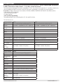
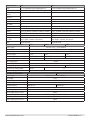
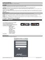
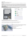
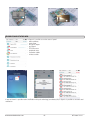
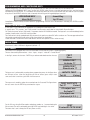
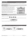
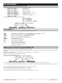
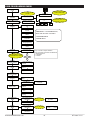
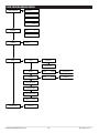
kX
Series
alarm control unit
user manuaL
EN 50131-3
EN 50131-6
CEB T014
www.amcelettronica.com
C24/64 GSM v1.0
important Notes
• The following manual has been prepared to provide assistance to users who use the system. All those who
use the systems listed in this manual must be authorized.
• The information contained in this document are property of AMC Elettronica s.r.l.
• All information contained in this document is subject to change without notice.
•
Every part of this manual should be interpreted and used only for the purposes for which it was drafted, the
use other than as prescribed must be authorized by AMC Elettronica srl, under penalty of forfeiture of the
guarantee.
• All trademarks, symbols and examples contained in this manual belong to their respective owners.
guarantee
AMC Electronics s.r.l. ensures that products are free from defects in workmanship.
The product is not installed by the manufacturer and can be used with other products not manufactured by AMC
Elettronica srl, the manufacturer does not guarantee or be held responsible for damage and / or theft or other
types of issues caused by an incorrect installation and / or configuration of the system.
Is not guaranteed to:
- improper use of the panel
- programming errors
- manipulation and vandalism
- wear and tear
- lightning, floods, fire.
AMC Electronics s.r.l. reserves the right to repair or replace the defective product within the limits established
for 24 months.
A different use from that stated in this manual will void the warranty.
The installation must be performed in a workmanlike manner by qualified personnel.
compliance
AMC Electronics s.r.l. declares that the K series alarm control unit are provisions of Directive 1999/5 /CE
On our web site www.amcelettronica.com
standards CEI 79-2:1998+Ab:2000, CEI EN 50131-3:2009 e CEI EN 50131-6:2008
All products mentioned in this manual are in accordance with the rules:
CEI 79-2:1998+Ab:2000, CEI EN 50131-3:2009 e CEI EN 50131-6:2008
certifier: IMQ – Sistemi di sicurezza
Grade: 2
Following is the list of normed products:
K4: control unit
K8: control unit
X412: control unit
X824: control unit
X864: control unit
PSTN carrier ATS type B on board K4 e K8 (ATS2: D2-M2-T2-S0-I0)*
SR 136: self powered siren (WD)
KLCD: keypad
KLight: keypad
KXIN: inputs expansion
KXOUT: outputs
Transformer 20VA
Transformer 25VA
Transformer 30VA
Xgprs/gsm: gsm - gprs module
IP1: IP module
* D2:transmission time 60sec. M2:max transmission time 120sec. T2:time of control information transmission 25h
- S0:no bearing replacement I0: no protection of the information.
www.amcelettronica.com
C24/64 GSM v1.0
manufaturer
AMC Elettronica s.r.l.
Via Pascoli 359
22040 Alzate Brianza
Como
Italy
Tel. +39031632780
Fax +39031632781
[email protected]
www.amcelettronica.com
www.amcelettronica.com
C24/64 GSM v1.0
introduction
X an K series are security control panel for building protection with certifification* CEI 79-2:1998+Ab:2000, CEI EN 501313:2009 e CEI EN 50131-6:2008 Grade: 2. Certifier IMQ – Sistemi di sicurezza.
The control panel are equipped of 4/8 zones, expandable to 12/24, even without zones expansions. It is possible to obtain more
zones by doubble and triple EOL split line. In case the split zones is not allowed, it is possible to use zones expansion.
X K series are able to notify one or more situations of ALARM, ROBBERY, TAMPERING AN TROUBLE with different carriers:
- PSTN LINE (tipo ATS2) ON BOARD
- GSM e GPRS optional module
- IP module optional
* after specific programming
The programmming can be via local keypad or a PC with specific software.
The main features are:
X412
4 -12 wired/radio/split doubble,triple EOL
2 on board - espandible to 5 (with 1 expansion)
32 users
X824
8 -24 wired/radio/split doubble,triple EOL
5 on board - espandible to 8 (with 1 expansion)
32 users
4
4
group
keypad
tag reader
event memory
phone numbers
carriers
other inputs
PC software
remote management
IP - GPRS
timers
4
4
4
1000
8 for SMS + 8 for protocols
PSTN on board, GSM/GPRS module, IP module
TAMPER line / mechanical antiopening tamper
yes
HTML page
apps (Apple - Android - Win phone)
4
4
4
1000
8 for SMS + 8 for protocols
PSTN on board, GSM/GPRS module, IP module
TAMPER line / mechanical antiopening tamper
yes
HTML page
apps (Apple - Android - Win phone)
SPECIFICATIONS
X 864
8 -64 wired/radio/split doubble,triple EOL
5 on board - espandible to 17 (with 4 expansion)
64 users
SPECIFICATIONS
zones
outputs
user code/tag/
remote
partitions
zones
outputs
user code/tag/
remote
partitions
group
keypad
tag reader
event memory
phone numbers
carriers
other inputs
PC software
remote management
IP - GPRS
timers
4 per day week
4 per day week
8
4
8
4
1000
8 for SMS + 8 for protocols
PSTN on board, GSM/GPRS module, IP module
TAMPER line / mechanical antiopening tamper
yes
HTML page
apps (Apple - Android - Win phone)
8 per day week
www.amcelettronica.com
C24/64 GSM v1.0
SPECIFICATIONS
zones
outputs
user code/tag/
remote
partitions
group
keypad
tag reader
event memory
phone numbers
carriers
other inputs
PC software
remote management
IP - GPRS
timers
K4
4 -12 wired/radio/split doubble,triple EOL
2 on board - espandible to 5 (with 1 expansion)
32 users
K8
8 -24 wired/radio/split doubble,triple EOL
2 on board - espandible to 5 (with 1 expansion)
32 users
4
4
4
4
4
1000
8 for SMS + 8 for protocols
PSTN on board, GSM/GPRS module, IP module
TAMPER line / mechanical antiopening tamper
yes
HTML page
apps (Apple - Android - Win phone)
4 per day week
4
4
4
1000
8 for SMS + 8 for protocols
PSTN on board, GSM/GPRS module, IP module
TAMPER line / mechanical antiopening tamper
yes
HTML page
apps (Apple - Android - Win phone)
4 per day week
ELECTRIC SPECIFICATIONS
X412
power supply
out voltage
Voltage range
Max consuption
0.18A
board consuption
max current out
Max volatge ripple
max recharge bettery current
back up battery
max curret on Load terminal
87mA@18V ~
1.5A
max current out
Max volatge ripple
max recharge bettery current
back up battery
max curret on Load terminal
power supply type (en 50131)
www.amcelettronica.com
90mA@18V ~
1.8A
12V 7Ah
12V 17Ah
700mA
1A
type A
K4
power supply
out voltage
Voltage range
Max consuption
board consuption
90mA@18V ~
400mV
800mA
power supply type (en 50131)
ELECTRIC SPECIFICATIONS
X824
X864
230 VAC -10% + 10% 50/60Hz
13.8 V
9 - 16 V
0.2A
0.2A
80mA@18V ~
K8
230 VAC -10% + 10% 50/60Hz
13.8 V
9 - 16 V
0.18A
85mA@18V ~
1.5A
400mV
800mA
12V 7Ah (recharged at 80% in 24H)
700mA
Type A
C24/64 GSM v1.0
enable installer access
This parameter is used to allow installer to enter in technical editor. When this parameter is set to 1, the installer can enter in the
his menù. Key the personal code and with down error go to parameter ENABLE INSTALLER ACCESS,Press enter and set 1 to allow.
(0=not allowed)
notifications
The notification system is a list of alarms and errors from the control unit. When the red LED on the keypad turns on, the control
unit is notifying that there are events to read. Pressing the CANCEL key accesses the notification screen. In the figure, the system
shows that there are 3 notifications to read. They can be read after inserting an enabled code.
Fig 1 the system shows 3 notifications
3 Events
fig 1
Fig 2 When the code is entered, the system shows the notifications in chronological order. You can scroll through the log using
the up arrow key.
Fig 3 When they have been read the red LED will turn off and the
message in the figure will appear
[
]
16:35 - 27/02/13
lounge radar alarm
fig 2
<<
NO NEW
>> fig 3
<< EVENT >> #Exit
events menu
The control unit saves each system operation and occurrence.
The system can save 1000 events with rotating update system. Once the log capacity is full, the system will delete the oldest event
to make space for new ones. Is it possible read the event log sort by type.
EVENTS MEMORY
All
Fig1 Reading menu for all events
EVENTS MEMORY
Unread
Fig 2 Reading menu for only unread events
EVENTS MEMORY
Alarms
Fig 3 Reading menu for only alarm events
EVENTS MEMORY
Anomalies
Fig 4 Reading menu for events connected to operating errors
EVENTS MEMORY
Arming/Disarming
Fig 5 Reading menu for system arming and disarming events
EVENTS MEMORY
Users
system info
Fig 6 Reading menu for user accesses
The control panel has a quick menu to access to basic information, during in the disarm status, if is keyed CANCEL button many
times it is possible to access information:
- quick event log menù
- PSTN status
- GSM status
- Battery status
- Main Power status
- Internet status
- Cluod connection status
- Firmware version
- Hardware status
www.amcelettronica.com
KX user V.1.0
6
activate outputs menu
The control unit has a system with a synoptics panel for quick activation of the outputs associated to a user code. Once entered in
the output activation menu, press ENTER and go to the associated outputs. Use the vertical arrow keys to activate and deactivate.
The figures to the side show the output activation screens. The
outputs that can be activatedare only those showing 0=deactiACTIVATE
vated and 1=activated.
OUTPUTS
All outputs marked with a dash cannot be activated because
they are programmed with other functions.
[05] name output 05
Once you have entered the activation menu, use the horizontal
0---0---------arrow keys to move from one output to the other and the vertical
arrow keys to activate or deactivate
[05] name output 05
(up arrow = activate, down arrow = deactivate)
0---1----------
enable remote management
If enabled, this parameter allows connection to the control unit via software. Enter the enable remote management menu and
change the parameter from 0 to 1. This way you can connect using the programming software.
ENABLE
TELEMANAGEMENT
TELEMANAGEMENT
Enabled
1
change code menu
If you have an enabled user code (master code) you can change your own code and the code for other users.
Once you have entered the CHANGE CODES, use the vertical arrows to select the user and press ENTER to change the codes.
CHANGE
CODE
CODE: User Nr 01
111111
date/time menu
Set the date and time on this menu
Enter the menu, press ENTER to change
Press ENTER again to enter the day of the week (1 for Mon, 2 for Tue...0 for sun)
Press the Right arrow to enter the day/month/year/hours/minutes in sequence Confirm with ENTER
menu TCP/IP
ip addresses
With this parameter it is possible to set IP address for IP Board:
First enable IP board from peripheric menu.
select DHCP to 1 for automatic setting, wait few minutes after exit from menu. In case doesn’t work:
- set 0 and set static IP and other parameter of network
IP address: eg. 192.168.000.008
Subnet mask: 255.255.255.000
Gateway: 192.168.001.001
DNS1: 008.008.008.008
DNS2: 208.067.000.000
For complete all parameter it is important to know the network parameters where the IP is connected.
Set the free static address for ip board, complete all parameters.
Exit from menu and wait few minutes. When the IP is connected must be see:
green led = steady (IP enable on peripheric)
orange led = blink machine running (when the led is steady or in OFF the machine nor run)
1° red led = off cloud connected (turn ON disconnected)
2° red led = off internet connected (turn ON disconnected)
little red = lan speed (OFF=10 ON = 100MB)
NOTE: when the system is in DHCP is important to know that the router assign IP to the machine (in some case is
necessary wait few minutes, or set the roueter to do this).
www.amcelettronica.com
KX user V.1.0
7
cloud parameters
DON’T MODIFY THIS FIELD this is the cloud address
account
I this menu are all parameter that used for registartion to the cloud. ( for APP)
username:it used for name ID, the same name must be inserted to the APP during to the registration panel
password: password, the same password must be inserted to the APP during to the registration panel
UID CODE: this code is most important because is the unique identification code of panel. Must be inserted to the APP with all
number and characters IDENTICAL.
NOTE:it is possible have the same password and username with different UID in the same APP (main house, beach
house etc.)
enable notific.
With this parameter it is possible to enable and disable smart notification in phone APP when it closed.
ALARM: when the system trig in alarm it is possible receive notification on smartphone (even when the application is closed)
USERS: when is enabled every action by all user are sent by notification APP (even when the application is closed)
ARMING:When is enabled every arm and disarm for each program are sent by notification (even when the application is closed)
For enable notification turn from 0 to 1 every single voice:
eg. ALARM = 1 (ENABLED) ALARM=0 (DISABLED)
AMC amanager app
AMC MANAGER is an application for smrtphone that allow end user to manage many parameters of panel:
- arm and disarm all partitions of panel
- bypass all programmed zones
- turn ON and OFF all programmed output
- monitoring system status
- back up battery
- main power
- all type of Tamper
- gsm signal
- PSTN line status
- peripheral status
- connection cables
- wireless trouble
- Log events
register app
After download APP is necessary to register it.
www.amcelettronica.com
8
KX user V.1.0
Complete all field:
EMAIL: that you can receive directely to the mobile
Password: create a password for register
After these operations press login and wait email from Cloud AMC, when the mail arrived press CONFIRM button to confirmation
registration.
Important: if don’t receive mail check in junk mail, if don’t work the confirmation button DON’T USE google mail
important with Android: when you push confirm button must be open the APP, if this do not happen, go in application management, find broswer application and delete default preference. Open again mail message and
confirm with button.
add panel to the app
After registration the app open the section where is possible ADD panels, press + to add panel.
Name is that the installation eg. main Home.
ID: is the UID CODE that you found in tha menu ACCOUNT of TCP IP in the panel
USERNAME and PASSWORS: are be the same that found in ACCOUNT menu in the panel
It is possible select a template for map, or use a custom image, or take a photo from internal camera.
After this it is possible to manage panel ( in pic it is possible to see 3 panel in the same APP)
In figure it is possible to see the map when the phone is in land screen
(horizontal). It is possible to add and set in right position the zone and
the output. Select the photo for each zone and outs.
The app show when the zone is:
ready: green circle
open: orange circle
alarm: red circle
it is possible check and move programmed outs.
www.amcelettronica.com
9
KX user V.1.0
troubles and status info
In figure it is possible to see the status of panel:
- back up battery
- main power
- all type of Tamper
- gsm signal
- PSTN line status
- peripheral status
- connection cables
- wireless trouble
In case of alarm it is possible receive notification with push technology (save battery life) In figure it is possible to see events and
notification.
www.amcelettronica.com
10
KX user V.1.0
programming and cancelling keys
Programming the keys can ONLY be done by an enabled user. This same user can create keys for all selected users.
Selected the PROGRAMMING KEYS menu, confirm with ENTER, select the user using the vertical arrow keys, send the learning
command by pressing ENTER, 15" countdown will start during which the LEDs on the READER will flash and the user must place
a key close to the READER when the code is learned, the led stop, and in keypad diplayed succesfull.
Insert Key
by 15 sec.
PROGRAM KEY
User Nr 01
Cancellation is done in exactly the same manner as programming. Once the user to be cancelled is selected, press ENTER to confirm
cancellation.
credit management
In this menu is it possible enter the parameters for sending the credit request SMS.
A specific menu “TEL. provider" and "SMS provider" can be used to enter data for Other Mobile Phone Providers.
For Check the correct value of SIM credit, is important that the KEYWORD be entered. The keyword is a word immediately before
number of credit value, in the SMS sent by provider.
The Credit value is always updated each time the control unit performs a data CMS call or sends an sms. The message received from
the provider containing the credit value will be shown directly on the display.
Credit threshold is the minimum level credit before send the info. (default is 3€ or other currency)
menu timer
This parameter is used bypass the automatic timer arming. If is set a timer, is it possible switch the arm/disarm operation in manual.
When there is value 0 the timer is bypassed. (default = 1)
test menu
The control unit is equipped with a test tool to be able to verify that the system is operating properly.
The tests that can be performed are: - sirens - inputs - outputs - voice call - Contact ID call
In the fig. it screens the siren test. ENTER key to activate and deactivate the siren test
TEST
Siren
SIREN TEST
Activate ??
SIREN TEST
Disactivate ??
The inputs test is performed by counting down programming zones. In the figure there
are 34 inputs to test. After test (by passing in front of sensors) press enter, in case
some sensor don’t work the system will show that sensor.
INPUTS TEST
Tot:34
V-stop
The output test is made by select the out and activate for 5 seconds. The figure shows
the test screen. Use the ENTER key to activate the output.
TEST OUTPUTS
Tot:17
V-start
01-output one
Activate??
01-output one
Activated (4.3.2...)
For the CID test, the call will be made to telephone number no. 1, communicating the
life test event. The call is activated by pressing ENTER and waiting for it to arrive.
The event that is sent is always the life test (event no. 602).
www.amcelettronica.com
11
TEST
ContactID PSTN/GSM
KX user V.1.0
using the system
As previously described, the control unit has 4 partials and 4 arming groups.
The partials consist of arming and disarming programs that include inputs and can be freely associated to users and timers.
The groups, are clusters of partials that can also be freely associated to users and timers. The groups are created to make it easier
to arm scenarios very easily and intuitively.
ARM/DISARM partials
When the system displaying the date and time, digit personal code (default 111111).
The screen that will appear: fig. 1
After the confirm of activation, a horizontal synoptics panel appears
ARM
fig1
that indicates the arming choice (fig. 2). By using the number keys, is
SYSTEM
it possible select the number of the partial and/or partials to be armed. Figure 3 shows the activation of partial 1, the line above shows
1-8=PRG
the name and the line below shows which partial was selected. Fig. 4
fig2 0=TOT
-------shows the activation of 2 partials (1 and 2). The flashing cursor is on
partial 2, therefore the name that appears is the one for P2.
program 1
fig3
Note: partial selection is step-by-step so pressing the number of
the partial more than once turns it off and back on.
1-------
fig4
perimetric
12------
ARM/DISARM groups
Each group can be given a name and be associated with the desired partials.
Once programmed, activation is done in the same manner as the partials with the only difference being that activation of the 4
available groups is done using the 4 arrow keys:
G1
G2
G3
G4
After keyed code and confirmed it, pressing one of the 4 arrow keys will select the group with the related name and associated
partials (fig 2). Confirm with ENTER
fig2
PERIMETER
-234----
In the figure, the group called "PERIMETER" is made up of 3 partials (2-3-4)
shortcut
The control panel has 2 type of PANIC shorcut, silent with G2 and G3, keyed in the same time for 2 seconds, siren with G1
and G4. Is it possible link the activation commands directely to the number button. If one key number is pressed for few second
the linked out will turn ON or OFF, this operation is displayed directely in keypad LCD (fig1)
1
garden light
activate
www.amcelettronica.com
1
12
garden light
deactivate
KX user V.1.0
sms management
ARM/DISARM THE CONTROL UNIT VIA SMS
To arm and/or disarm the control unit you must have a user code:
UPWD:111111 ARM=T TOTAL ARMING
UPWD:111111 ARM=1 PARTIAL1 ARMING
UPWD:111111 ARM=123 ARMING OF PARTIALS 1 - 2 - 3
UPWD:111111 DISARM=T TOTAL DISARMING
UPWD:111111 DISARM= 2 DISARMING OF ONLY PARTIAL 2
UPWD:111111 DISARM= 12 DISARMING OF PARTIALS 1 - 2
UPWD:111111 ARM?
ARMING STATUS REQUEST FROM THE CONTROL UNIT
ARM = 0 DISARMED
ARM =T TOTAL ARMED
ARM = 12 PARTIALS 1 - 2 ARMED
UPWD:111111 ARM=T TOTAL ARMING
Without spaces
One space
Without spaces
sms commands
This is the complete list of all of the system programming/querying commands
LOCK
TPWD
UPWD
ARM
DISARM
OUT.x IN.x
TEL.x : =
?
SYSTEM UNLOCK COMMAND (to allow to modify phone numbers) (LOCK=1 for unlock)
TECHNICIAN PASSWORD DECLARATION (TPWD:000000 CODE)
USER PASSWORD DECLARATION (UPWD:111111 CODE)
ARMING COMMAND (T=total 1=partial 1 etc.)
DISARMING COMMAND (
OUTPUT SELECTION COMMAND
INPUT SELECTION COMMAND
TELEPHONE SELECTION COMMAND
IS USED FOR USER/INSTALLER CODE
COMMAND FOR ASSIGN PARAMETER
REQUEST INFO COMMAD
how to create a REQUEST AND programming sms
To send a command to the system you need follow a few simple rules:
For example, in order to the installer to change a telephone number, he must first have authorisation from the system owner (system
unlock)
UPWD:111111 LOCK=OFF this command unlocks the programming via sms for 20 minutes.
This unlock must be done by the system owner. (final user)
Now the installer can give the command:
As you can see, the message is made up of two commands:
TPWD:000000 TEL.1=+393358554574
Without spaces
One space
Without spaces
1 - the password declaration (TPWD:000000 or UPWD:111111) This command requires the (: ) (colon) to enter the code.
2 - this is the operational part of the message that uses the (=) to assign the operation, the (?) to request information (a few examples follow)
TEL.1=+393358554574 setting telephone number response from the system TEL.1:OK
OUT.2=onoutput 2 activation response from the system
OUT.:OK
OUT.4=off deactivation of output 4 response from the system OUT.4:OK
IN.2? input 2 status request response from the system IN.2=OP (if open) IN.2=CL (if at rest)
www.amcelettronica.com
13
KX user V.1.0
user programming menu
PERSONAL
CODE
5
6
7
8
9
Arming single Program,
confirm with Enter
program 1
1---
0=TOT
1-8=PRG
---------
ENABLE INSTALLER
ACCESS
MENU
EVENTS
2
4
0
Select G buttons for
groups
ARM
SYSTEM
3
1
Arming group
Perimeter, sum of the
program 1 and 2
perimetric
12--
ENABLE ACCESS
Installer
1
EVENTS MEMORY
All
EVENTS MEMORY
Unread
EVENTS MEMORY
Alarms
EVENTS MEMORY
Anomalies
ATTENTION : a non MASTER user,
when enter his menu can ONLY:
- PROGRAM KEYS
- ERASE KEYS
EVENTS MEMORY
Arming/Disarming
EVENTS MEMORY
Users
ACTIVATE
OUTPUTS
[01] output one
0100---------up
Use the joistik to select
and activate the outputs
dx
sx
Keys sx and dx for outputs selection
Keys up and down for activate and deactivate
- = Not programmed
0 = Deactivate
1 = Activate
down
ENABLE
TELEMANAGEMENT
CHANGE
CODE
TCP/IP
Cloud parameters
TCP/IP
Account
TELEMANAGEMENT
Enabled
CODE: User Nr 01
111111
CODE: User Nr 32
------
USER NAME
Admin:
PASSWORD
1234
TCP/IP
Enable notific.
0
UID CODE
NOTIFIC. TCP/IP
Alarms
1
NOTIFIC. TCP/IP
Users
1
NOTIFIC. TCP/IP
Arming
1
PROGRAMMING
KEYS
PROGRAM KEYS
User Nr 01
Insert Key
by 15 sec.
Press ENTER
PROGRAM KEYS
User Nr 32
DELETE
KEYS
DELETE KEYS
User Nr 01
Press ENTER
Deleting Key
Success!
# Exit
DELETE KEYS
User Nr 32
www.amcelettronica.com
14
KX user V.1.0
user programming menu
CREDIT
MANAGEMENT
Tel provider
Sms. provider
KEYWORD
Credit Threshold
[Euro] 3
VOLUME
SETTING
VOLUME
Level
2
Speakerphone
MENU
TIMER
TIMER
BYPASS
MENU
TEST
TEST
Siren
1
0
SIREN TEST
Activate??
SIREN TEST
Disactivate??
TEST
Zones
INPUTS TEST
Tot:08
V-Stop
INPUTS TEST
01-input one
TEST
Outputs
TEST OUTPUTS
Tot:05
V-Start
01-output one
Activate??
TEST
ContactID PSTN
TEST
ContactID GSM
TEST
Ademco4+2 PSTN
TEST
Ademco4+2 GSM
MENU
DATE/HOUR
www.amcelettronica.com
Sun 01/01/00
08:00:00
15
KX user V.1.0
index
important Notes............................................................................................................................................... 2
guarantee......................................................................................................................................................... 2
compliance....................................................................................................................................................... 2
standards CEI 79-2:1998+Ab:2000, CEI EN 50131-3:2009 e CEI EN 50131-6:2008.......................................... 2
manufaturer.................................................................................................................................................... 3
introduction.................................................................................................................................................... 4
enable installer access.................................................................................................................................. 6
notifications.................................................................................................................................................... 6
events menu...................................................................................................................................................... 6
system info........................................................................................................................................................ 6
activate outputs menu................................................................................................................................... 7
enable remote management.......................................................................................................................... 7
change code menu.......................................................................................................................................... 7
date/time menu................................................................................................................................................. 7
menu TCP/IP........................................................................................................................................................ 7
ip addresses....................................................................................................................................................... 7
cloud parameters............................................................................................................................................ 8
account . ......................................................................................................................................................... 8
enable notific................................................................................................................................................... 8
AMC amanager app.......................................................................................................................................... 8
register app....................................................................................................................................................... 8
add panel to the app........................................................................................................................................ 9
troubles and status info................................................................................................................................ 10
programming and cancelling keys............................................................................................................. 11
credit management......................................................................................................................................... 11
menu timer........................................................................................................................................................ 11
test menu........................................................................................................................................................... 11
using the system............................................................................................................................................... 12
ARM/DISARM partials........................................................................................................................................ 12
ARM/DISARM groups......................................................................................................................................... 12
shortcut............................................................................................................................................................ 12
sms management............................................................................................................................................. 13
ARM/DISARM THE CONTROL UNIT VIA SMS.......................................................................................................... 13
sms commands................................................................................................................................................. 13
how to create a REQUEST AND programming sms...................................................................................... 13
user programming menu .............................................................................................................................. 14
user programming menu .............................................................................................................................. 15
www.amcelettronica.com
C24/64 GSM v1.0


![[Manuale utente] - v1.0.KX_series_utente-IT](http://vs1.manualzilla.com/store/data/006161557_1-fcb082d2ecb2b5d65eea662d7e490087-150x150.png)