1
OKINA
SEIMW36T-V53DN
36x Wide Dynamic ICR IR
PTZ Camera
OPERATION MANUAL
English
WARNING
TO REDUCE THE RISK OF FIRE OR ELECTRIC SHOCK, DO NOT EXPOSE THIS
PRODUCT TO RAIN OR MOISTURE. DO NOT INSERT ANY METALLIC OBJECTS
THROUGH THE VENTILATION GRILLS OR OTHER OPENINGS ON THE EQUIPMENT.
This symbol indicates that dangerous voltage constituting a risk
of electric shock is present within this unit.
This symbol indicates that there are important operating and
maintenance instructions in the literature accompanying this
unit.
CAUTION: TO REDUCE THE RISK OF ELECTRIC SHOCK, DO
NOT REMOVE COVER ( OR BACK). NO USER SERVICEABLE
PARTS INSIDE. REFER SERVICING TO QUALIFIED SERVICE
PERSONNEL
FCC COMPLIANCE STATEMENT
FCC INFORMATION: THIS EQUIPMENT HAS BEEN TESTED AND FOUND TO COMPLY WITH THE LIMITS FOR A CLASS A DIGITAL DEVICE, PURSUANT TO PART 15 OF
THE FCC RULES. THESE LIMITS ARE DESIGHEND TO PROVIDE REASONABLE PROTECTION AGAINST HAMRFUL INTERFERENCE WHEN THE EQUIPMENT IS
OPERATED IN A COMMERCIAL ENVIRONMENT. THIS EQUIPMENT GENERATES, USES, AND CAN RADIATE RADIO FREQUENCY ENGERGY AND IF NOT INSTALLED AND
USED IN ACCORDANCE WITH THE INSTRUCTION MANUAL, MAY CAUSE HARMFUL INTERFERENCE TO RADIO COMMUNICATIONS. OPERATION OF THIS EQUIPMENT
IN A RESIDENTIAL AREA IS LIKELY TO CAUSE HARMFUL INTERFERENCE IN WHICH CASE THE USER WILL BE REQUIRED TO CORRECT THE INTERFERENCE AT HIS
OWN EXPENSE.
CAUTION: CHANGES OR MODIFICATIONS NOT EXPRESSLY APPROVED BY THE PARTY RESPONSIBLE FOR COMPLIANCE COULD VOID THE USERS‘S AUTHORITY TO
OPERATE THE EQUIPMENT.
CE COMPLIANCE STATEMENT
WARNING: THIS IS A CLASS A PRODUCT. IN A DOMESTIC ENVIRONMENT THIS PRODUCT MAY CAUSE RADIO INTERFERENCE IN WHICH CASE THE USER MAY BE
REQUIRED TO TAKE ADEQUATE MEASURES.
CAUTION: BEFORE ATTEMPTING TO CONECT OR OPERATE THIS PRODUCT, PLEASE READ THE LABEL ON THE BOTTOM AND USER'S MANUAL CAREFULLY
PRECAUTION
• All installation works should be done by qualified service person or system installer.
• Do not try to open or disassemble the PTZ. To prevent electric shock, do not remove the screws or cover. There are no userserviceable parts inside. In case of maintenence, contact qualified service personnel.
• Handle the PTZ carefully. Do not hit, strike or shake the PTZ. This will cause damage the mechanic parts and avoides the warranty.
During the transport or storage, the PTZ should be packed in original packing, which will protect from pressure, vibration and
humidity.
• Do not use strong or excessive liquid to clean the PTZ and cover. Use dry cloth or mild cleaning lotion, and wipe gently.
• Do not operate the PTZ among the specified condition. Please refer to the section “Specification” for detailed information.
• Do not expose the indoor PTZ to water or moisture. The indoor version of PTZ is not designed to resist high humidy and water, these
may cause permanent damage and avoids the warranty. For indoor application with extrem wet condition or area contains water or
high-humidity, use the outdoor model instead. When the indoor PTZ get wet, turn off the power immediatly and send to qualified
service personnel .
• Do not point the camera to strong light source ( e.g. Sun-Light, Beamer or laser pointer). This will cause permanent damage to the
sensor and avoids the warranty.
• Read this user's manual carefully before operating, and make sure that the operation and installation follow your local electric safety
standards or regulation.
• Do not install the PTZ in orientation other than designed. The PTZ is designed for operation looking-down. Other orientation of
installation will prevent the heat-sink function and cause damage.
• Do not touch the PTZ clear cover with bare hands or any object. These will leave permanent scratches on the surface and decrease
the image quality. Scratches are not covered by the warranty.
• Do not install and operate this PTZ in a flammable and explosive environment.
• Make sure that the installation is done according to the local electricity safety regulation of your country.
• Before installation or mentainence, make sure that the PTZis disconnected from the power source.
• Do not use any power source other than specified in the specification, in order to prevent damages. In case of doubt, see section
“Specification” for details.
• Handle the device during the installation carfully. Falls or extreme vibration will cause irrepairable damages and avoid the warranty.
• Do not install or operate the PTZ near any high-voltage devices or high-voltage cable. The safety distance should remain at least 50
m.
• To archive best image quality, its recommanded to use underground cable shielded with steel tube. Do not install the cable without
any protection.
• In area or region which has high inductive power, such as high voltage transformer stations, or high electrostatic discharges, such as
thunder, it is necessary to use additional lighning-proof equipments or lightning rob for protection.
• For outdoor installation, lightning-proof and grounding of the device should be considered. Please refer to the industrial saftey
regulation and request of your country
• Grounding of the PTZ should consider with anti-interference and fulfill the saftey requirements. Do not connect the ground with
short-circuited or other high-voltage electric network.
• The resistance of down conductor should not exceed 4 Ohm, and its thickness should be at least 25mm²
• This PTZ is protectd against high-voltage pulse up to 1500V
• The outdoor model meets the Ip66 standard for water and dust proof. Do not install the in-door model for out-door application. Make
sure that the installation is protected from long-time water-drop or spatter, which may damage the appliance.
• Make sure that the enviroment of installation meets the requirement of the appliance, such as holding the weight, enough spaces for
bracket and power supply.
Technical specification are subjects to change without prior notice. Manual may contain mistake or print error.
All trademarks mentioned belong to their respective owners.
English
CONTENT
Installation
Unpacking .................................................................................................. 1
I/O Interface ... ............................................................................................ 1
Basic Setup ................................................................................................. 1
Telemetric .................................................................................................. 1
ID / Protocol ................................................................................................ 1
RS-485 Termination ..................................................................................... 1
Mounting ..................................................................................................... 1
Application Example . ................................................................................... 2
RS-485 Transmission ...................................................................................2
Video Transmission ..................................................................................... 2
OPERATION
Powering the PTZ ........................................................................................ 3
Work with PTZ ............................................................................................. 3
Camera functions ........................................................................................ 3
OSD
Enter the OSD ............................................................................................. 4
Main Menu .................................................................................................. 4
System Setting ............................................................................................ 4
Edit dome label ...................................................................................... 4
Initial Info .............................................................................................. 4
Display Setup
Motion ................................................................................................... 5
Motion - Advanced ..................................................................................5
Setting .................................................................................................. 5
Clear..................................................................................................... 5
Password Setting ................................................................................... 5
Clock Setting ......................................................................................... 5
Camera Setting
IR CUT Filter ......................................................................................... 6
Advance Setting ................................................................................... 6
Function Setting
Presets ................................................................................................
Scan ....................................................................................................
Pattern .................................................................................................
Tour .....................................................................................................
Zones ..................................................................................................
Time Running ........................................................................................
6
6
7
7
7
7
Window Blanking ........................................................................................ 8
Alarms ....................................................................................................... 8
Language .................................................................................................. 8
Appendix
OSD Map .................................................................................................. 9
Dip Switch settings .................................................................................... 9
ID Settings ................................................................................................ 10
SPECIFICATIONS ............................................................................................ 11
WARRANTY ..................................................................................................... 11
English
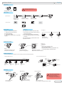
INSTALLATION
Unpacking
G50IR-MKII
HIGH-SPEED PTZ
CAMERA SERIES
Keep the original box for
possible transport in the future.
OPERATION MANUAL
Ver. 1.0
ENGLISH
GERMAN
SEIMW36T-V53DN
Manual
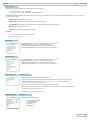
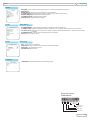
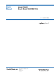
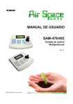
I/O Interface
Connectors
24V
AC
POWER
RJ-11
RS-485
BNC
VIDEO
Red:AC24V
Black:AC24V
24V AC / 2A
Inner Pin: Video +
Outer Conn.:Video -
ALARM
Green: RS-485 +
Yellow: RS-485 -
Accessories
Power
Sensor
Switch
Keyboard
Controller
DVR
Monitor
Telemetric
Basic Setup
Check-List before installation:
For telemetric control, make sure that:
1. Telemetric Protocol setting
2. Dome ID setting
3. Termination setup
3. Necessary Accessories ( e.g Power
supply)
1. All devices are set with same protocol
and comm setting.
2. All PTZ devices have an unique ID.
3. Control cable (Rs485) are connected
properly.
For controller setup, please refer to the
operation manual
Example:
Protocol: B02
Baud-Rate: 9600
ID:1
ID:2
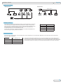
ID & protocol setup
Step 1
Loose the screws (4 pcs)
and open the base-part
Step 2
Take off the base
part for configuration
Switch 1:
ID Setup
Switch 2:
Digit 1 to 5: Protocol setup
Digit 6,7: Baud-Rate
Digit 8: RS485 Termination(default: off)
For setting details, please refer to
Step 3
Set the ID, Protocol
Baud-Rate and Termination
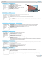
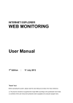
RS485 Termination
For a smooth telemetric operation, it is necessary to set the termination properly.
2. Star-Form Connection
1. Chain Connection
RS 485+
ID:2
Termination
ON
RS 485Keyboard
Termination
ON
ID:1
Termination
ON
ID:2
Termination
OFF
ID:3
Termination
OFF
ID:3
Termination
ON
ID:1
Termination
ON
ID:4
Termination
OFF
ID:4
Termination
ON
Keyboard
Termination
ON
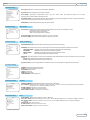
Mounting
360°
Pan
Use 4 Screws to fix
(not included)
Reverse-Mount
Wall-Mount
Surface-Mount
180°
Tilt
Use 4 Screws
to fix (not
included)
Wall-Mount Bracket
(optional accessory)
Make sure the installation
enviroment provide enough
space for pan and tilt
movement, else it might
damage the mechanic parts.
Use 4 Screws to fix
(not included). Change SETTING in OSD
1
English
INSTALLATION
Application Example
Multiple PTZ
Simple PTZ
Video output
Video output
RS-485
Line
DVR
Monitor
Keyboard
Controller
Power
Power
Power
Power
Keyboard
Controller
DVR
Monitor
RS-485 Daisy-Chain or Star-Form
connection, Termination on the ends.
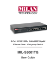
RS485 Transmission
The distance of RS485 transmission between 2 nodes depends on the baudrate. The table on the right side shows the maximum range of every baudrate, assuming a AWG24 wire-pair is used. Note the range might be shorter
than given here, since the cable quality or interferences may affect the
transmitted data, and cause invalid command.
In star-form connection, it might be necessary to use RS-485 Distributor, to
ensure the signal quality of the transmission.
Baud Rate
Max. Distance
2400 bps
4800 bps
1700m
9600 bps
19200 bps
1100 m
700m
4oom
Video Transmission
For video signal transmission, coaxial cable with 75 Ohm impedence is recommended. Depends on the cable type, the transmission
distance might be different:
Cable standard
Max. Distance (m /ft )
RG 59 /U
229m / 750 ft
RG 6 /U
305m/ 1000 ft
RG 11 /U
457m / 1500 ft
The actually transmission distance can vary from the data shown on the table left. It is
necessary to consider the environmental in fluences when planning the installation. If
the transmission requires a larger distance, you may use video-balun or fiber-transmitter
to extend the distance. Contact your local sales representative for further information.
2
English
OPERATION
Powering the PTZ
After connected to power source, the PTZ will perform the self-test with pan, tilt and zoom, and
displays the initial screen with following information:
S/N: Serial number of the PTZ
FIRMWARE: Current firmware version
PROTOCOL: Protocol version
DOME ADDRESS: the PTZ ID
COMM: Baud-rate and serial settings
The initial screen will disappear once the PTZ camera receives a user command. If the function
“Power up action” is defined with certain action, it will execute the action immediately.
Work with PTZ
In order to work with the PTZ function, you need a device for telemetric control, such as a controller keyboard, a PTZ software or DVR with PTZ control.
Make sure that the protocol, baud-rate setting are done correctly as described in section “Installation”, or refer to the operation manual of the controller
device.
Beside the pan, tilt and zoom function, this camera provides also auxiliary function for surveillance, such as preset position, self-learning tours and
pattern, which consist the more preset position. The setting of camera and auxiliary function can be accessed either directly from the keyboard, or
through the On-Screen-Display ( OSD) menu, a text-based navigation menu projected on the monitor screen.
PAN, TILT and ZOOM Functions
In order to work with the PTZ function, you need a device for telemetric control, such as a controller keyboard, a PTZ software or DVR with PTZ
control. Make sure that your controller device supports these functions.
Zoom in
PAN
Zoom out
The PAN and TILT function are mostly
performed from the Joystick on the keyboard.
Please refer to the user’s manual of contoller
device for operation instruction
TILT
IRIS and FOCUS
In regular operation, the focus and iris will be regulated automatically to achieve best image quality. If case of need, you can adjust Iris and focus
setting by press the corresponding buttons on the controller device. The auto-focus will resume once a PTZ command is triggered.
FOCUS
Far
IRIS Close
IRIS Open
FOCUS
Near
Auxiliary Function
The auxiliary function provides user automated action, such as memorizing position and recalling by a direct input on the cotnroller device. Make
sure that the keyboard controller you use support these function, and refer to the manual for operation.
PRESET: A Pan-Tilt position which contains the zoom
setting. Up to 128 presets can be stored in the camera
SEQUENCE(PRESET TOUR): An auto-touring thourgh the defined,
stored preset positions. Each tour can contain up to 24 preset points.
Total 4 tours can be stored in the camera.
Preset 4
Preset 4
Preset X
Preset 1
Preset 3
Preset 2
Preset 3
Preset 1
Preset 2
PATTERN TOUR: A recording of user’s Pan, Tilt and
zoom up to 180 seconds. Up to 4 pattern tours are
supported
SCAN TOUR: A Pan-Tilt moving between 2 defined limits. Up to 4 scan
tours are supported
Right Limit
KB3N
Left Limit
Camera Functions
This PTZ camera provides also image enhancement functions, such as BLC, AGC, AE or the Day/Night Vision. Details will be introducece in the
section “OSD”.
3
English
OSD
Enter the OSD
The OSD menu can be activated by recall the preset position number 95
Press [SHOT] + [9] +[5] + [ENTER]
or Press 2 x [SHOT] + [9] + [ENTER]
withing 3 seconds.
Navigation from keyboard: To navigate through the OSD menu items, following keys are defined for OSD operation. Make sure your controller
device provide the keys:
[IRIS OPEN] Enters the sub-menu or confirm
[IRIS CLOSE] Cancel the current setting, or exit the selected menu item.
[UP], [DOWN] Move between menu lines( menu item), or adjust the selected value when entered.
[RIGHT] Enter a high-lighted menu item,
[LEFT] exit the menu item, equals to [IRIS CLOSE]
Symbols:
“→" : On the end of the line indicates a sub-menu.
: Shows current cursor.
Main Menu
MAIN MENU
-----------------------------------SYSTEM SETTING →
CAMERA SETTING →
FUNCTION SETTING →
WINDOW BLANKING →
ALARMS→
LANGUAGE→
EXIT
SYSTEM SETTING: contains setting parameter for the system.
CAMERA SETTING: Camera / image related settings
FUNCTION SETTING: PTZ and auxiliary function settings
WINDOW BLANKING: Privacy masking function and settings
System Setting
SYSTEM SETTING
------------------------------------EDIT DOME LABEL →
INITIAL INFO →
DISPLAY SETUP→
MOTION →
CLEAR →
PASSWORD SETTING →
CLOCK SETTING →
BACK →
EXIT
System Setting
EDIT DOME LABEL
LABEL: ►DOME1
BACK
EXIT
SYSTEM SETTING: contains setting parameter for the system.
CAMERA SETTING: Camera / image related settings
FUNCTION SETTING: PTZ and auxiliary function settings
WINDOW BLANKING: Privacy masking function and settings
Edit dome label
- Select DOME LABEL and enter with [RIGHT] or [IRIS OPEN]
- The input character starts to flash, use [UP] or [DOWN] to select the desired character and [RIGHT] for next input.
- Available characters appear in following order: “0” to “9”, ”A” to “Z” , “:”, “<”, “>”,”-” “{SPACE}” (empty sign).
- Use [LEFT] to move to previous character when edit.
- In case you need to delete a character, use the “SPACE”-character (Empty sign).
- When finished, press [IRIS OPEN] to save, or use [RIGHT] to move to last character and next to exit the editing mode.
- To dicard the setting, press [IRIS CLOSE] to exit.
- Select “BACK” to exit to “SYSEM SETTING” menu.
System Setting
INITIAL INFO
--------------------------------S/N XXXXXXXXXXXXXXX
FIRMWARE
v2.4
PROTOCOL: VIDO B02
DOME ADRESS:
001
COMM, 4800, N8, 1
BACK
EXIT
Initial Info
Initial Info show the following Info:
► Product Seriennumber
► Firmware version
► Protocol Setting
► Dome ID
► Baudrate
4
English
OSD SETUP
System Setting
Display Setup
[DOME LABEL] : show label name
[PRESET LABEL]: show preset label or scan label
[ZOOM LABEL]: show zoom ratio
[ZONE LABEL]: show zone Label
[DIRECTION LABEL]: show the coordinate position
[TEMPERATURE LABEL]: show the current dome
temperature
[TIME LABEL]: show the current time
[DATE LABEL]: show the current date
DISPLAY SETUP
--------------------------------------DOME LABEL
OFF
PRESET LABEL
OFF
ZOOM LABEL
OFF
ZONE LABEL
OFF
DIRECTION LABEL
OFF
TEMPERATURE LABEL OFF
TIME LABEL
OFF
DATE LABEL
OFF
BACK
Preset
label
Zone
label
Time
Date
Direction
label
Zoom ratio indicator
System Setting
Motion
MOTION
-------------------------------AUTOFLIP
ON
→ ON
PROPORTION PAN
PARK TIME
005
SCAN
PARK ACTION
POWER UP ACTION
FAN ENABLE
ADVANCE SETTING ->
AUTO
040
BACK
EXIT
Auto flip: The dome swing the PAN to 180°, when the limit of 90°TILT reach
Proportional Pan: Inversly controlling
Park time: Set the IDLE timer in minutes, and activates the action defined in “PARK ACTION”.
Park Action: Define the action when “Park time” activate. Selcetable: Preset 1-80, Scan 1-4, Pattern1-4,
Tour 1-4
Power Up Action: Start “Park Action” when power up.
FAN Enable: Define the temperature limit for the internal cooling fan.
System Setting
ADVANCE SETTING
-------------------------------EIS ANABLED
N/A
PRESET FREEZE
N/AI
IR HEADLIGHT
MANUAL
HEAD-DOWN
OFF
DEFOGGER
15
WIPER
BACK
EXIT
System Setting
CLEAR
------------------------------CLEAR ALL ZONES
CLEAR ALL PRESET
CLEAR ALL PATTERNS
CLEAR ALL TOURS
CLEAR ALL WINDOWS
FACTORY DEFAULTS
RESTART
BACK
EXIT
Motion
Advance Setting
EIS ANABLED : Electronic Image Stablizer. Depends on the camera model, it might not be available.
PRESET FREEZE: Freezes the preset image
IR HEADLIGHT: Performance of the IR-Headlight, selectable with Low, Medium, High or Manual.
HEAD-DOWN: When installing the PTZ reversed, turn on this option.
DEFOGGER: Defogger function in the camera bay.
WIPER: Starts the Wiper
Clear
The “CLEAR” function resets the settings to factory default.
CLEAR ALL ZONES: Delete all zones setting
CLEAR ALL PRESET: Delete all preset positions
CLEAR ALL PATTERNS:Delete all pattern setting
CLEAR ALL TOURS: Delete all tours setting
CLEAR ALL WINDOWS: Delete all privacy masking setting
FACTORY DEFAULT: Reset all setting and return to factory settings
RESTART: Restart the dome
Note: after using the option “Factory default”, all system setting and stored information such as preset, tour or pattern will be
erased permanently. Please make sure before proceeding.
System Setting
PASSWORD SETTING
--------------------------------OLD PASSWORD ******
NEW PASSWORD ******
CONF PASSWORD ******
ENABLE PASSWORD OFF
BACK
EXIT
System Setting
CLOCK SETTING
-------------------------------TIME:
HH:MM:SS
DATE:
YY/MM/DD
BACK
EXIT
Password Setting
The password function can prevent unauthorized access to the OSD and change the setting. It consists a 6 digit number
from 0-9 and can be disable.
OLD PASSWORD: Enter the old password
NEW PASSWORD: Enter the new password with 6 digit number
CONF PASSWORD: Enter the new passwor again
ENABLE PASSWORD: Activate the login function to the OSD
Default password: 000000
Supervisor password: 892226
Clock Setting
The system is equipped with a RTC (Real-Time Clock) and can be used to display the date/ time information on the
screen, or schedule enabled operation. In order to use these functions correctly, you need to setup at first.
TIME: Change the time setting
DATE: Change the date setting
Use [LEFT], [RIGHT] to move the cursor and use [UP], [DOWN] to adjust the value. When finished, press [IRIS OPEN] to
save the setting.
5
English
OSD
Camera Setting
CAMERA SETTING
--------------------------------------ZOOM SPEED
HIGH
DIGITAL ZOOM
ON
BLC MODE
OFF
SLOW SHUTTER
OFF
LINE SYNC
N/A
WDR MODE
IR CUT FILTER→
ADVANCE SETTING →
BACK
EXIT
Zoom Speed: Define the Zoom speed. Selectable: LOW/HIGH
Digital Zoom: Activate digital zoom, depend on Modul
BLC MODE: Back-Light Compensation mode. Use this option when the observed object has a strong
back-light such as the sun light or other light source.
SLOW SHUTTER: The slow-shutter allows a higher sensitivity by exposing the image sensor with a longer period of time,
incase the observed objects does not have much movement.
WDR MODE: Activate Wild Dymamic Range, depend on Modul
Camera Setting
IR Cut Filter
IR CUT FILTER
-------------------------------------IR CUT FILTER
COLOR
IR CUT ON TIME
N/A
IR CUT OFF TIME
N/A
BACK
EXIT
IR CUTTER: Enables the removal of Infrared Cutter Filter (IRC), also known as “DAY/NIGHT” mode.
- Color Mode: remains in the day mode
- Black: IRC remains in night mode.
- TIME: Controlled by the time schedule.
IR CUT ON TIME: When the IR Cutter should turn on, given in day time.
IR CUT OFF TIME: When the IR Cutter should turn off, given in day time.
Camera Setting
Advanced Setting
ADVANCE SETTING
--------------------------------------→ AUTO
AE MODE
SHUTTER
N/A
WB MODE
AUTO
R GAIN
N/A
B GAIN
N/A
HI RESOLUTION
ON
BACK
EXIT
ADVANCED SETTING: Enters the advenced setting module for the camera setting
AE MODE: Auto-Exopsure mode. This camera supports various exposure methods for different environment:
SHUTTER MODE:
IRIS MODE:
BRIGHTNESS:
AUTO:
In shutter mode, the camea changes the shutter speed to regulate light.
Regulate the Iris-openning to control the exposure
Regulates the exposure by changing the brightness control
Automatically regulates the exposure modes.
WB MODE: The camea supports ATW, Indoor and Outdoor mode of White balance, which chooses the correct color of the
image.
R-Gain: Regulates the red elements in the image color
B-Gain: Regulates the blue elements in the image color
High-Resolution:Turns the High-Resolution mode of the camera. only available on supported camera models.
Function Setting
FUNCTION SETTING
-------------------------------PRESET →
SCAN →
PATTERNS →
TOUR →
ZONES →
TIME RUNNING →
BACK
EXIT
Function Setting
Presets
PRESET
--------------------------------PRESET NUMBER
SET PRESET
SHOW PRESET
CLEAR PRESET
EDIT PRESET LABEL →
BACK
PRESET: Setup and manage the presents.
SCAN: Define and manage the scan tours.
PATTERNS: Pattern tours.
TOUR: Preset Tours
ZONES: Zone settings
TIME RUNNING: Scheduled actions
XX
Function Setting
SCAN
---------------------------------------SCAN SPEED
50
SET LEFT LIMIT
SET RIGHT LIMIT
RUN SCAN
CLEAR SCAN
EDIT SCAN LABEL →
BACK
EXIT
PRESET NUMBER: Selected preset position, supports up to 128 presets.
SET PRESET: Setup the preset position. Enter this menu, move the PTZ to desired positon and press [IRIS
OPEN] to store, or [IRIS CLOSE] to discard.
SHOW PRESET: Recall the preset position
CLEAR PRESET: Delete the preset position
EDIT PRESET LABEL : Assign the preset label.
Scan
SCAN SPEED: Define the scan speed, lowest 1 - fastest 50
SET LEFT LIMIT: Define the left point of scan tour, press [IRIS OPEN] to store, or [IRIS CLOSE] to discard.
SET RIGHT LIMIT: Define the right point of scan tour, press [IRIS OPEN] to store, or [IRIS CLOSE] to
discard.
RUN SCAN: Start the scan tour
CLEAR SCAN: Erase the stored scan tour
EDIT SCAN LABEL: Assign a name of the tour
6
English
OSD
Function Setting
Pattern
The Pattern-Tour is a custom-defined tour by recording user’s control action up to 180 sec per tour. This dome can
support up to 4 pattern tours.
PATTERNS
PATTERN NUMBER
XX
PROGRAM PATTERN
RUN PATTERN
CLEAR PATTERN
EDIT PATTERN LABEL →
BACK
EXIT
Function Setting
Tour
TOUR
--------------------------------------TOUR NUMBER
1
EDIT TOUR→
RUN TOUR
CLEAR TOUR
BACK
EXIT
Function Setting
A tour is a automated cruising through selected preset positions with individual speed and dwell time. This PTZ supports up
to 4 tours with 24 position each.
TOUR NUMBER: Currently selected tour
EDIT TOUR: Edit the selected tour
RUN TOUR: Start the selected tour
CLEAR TOUR: Delete the selected tour
Tour
EDIT TOUR
--------------------------------------P0-S-TM P0-S-TM P0-S-TM
00-0- 00 00-0- 00 00-0 - 00
00-0- 00 00-0- 00 00-0 - 00
00-0- 00 00-0- 00 00-0 - 00
00-0- 00 00-0- 00 00-0 - 00
00-0- 00 00-0- 00 00-0 - 00
00-0- 00 00-0- 00 00-0 - 00
00-0- 00 00-0- 00 00-0 - 00
00-0- 00 00-0- 00 00-0 - 00
BACK
EXIT
Function Setting
Edit Tour
PO : The preset position being included in the tour. If there is no preset position stored,please define the
preset at first.
S: The velocity when PTZ moves to this preset, between low1 - high 8.
TM: The dwell before the PTZ moves to next point. between 1-60 second
Zones
ZONE
-------------------------------ZONE NUMBER
SET LEFT LIMIT
SET RIGHT LIMIT
CLEAR ZONE
EDIT ZONE LABEL →
BACK
PATTERN NUMBER: Selected pattern tour
PROGRAM PATTERN: Record the tour. Enter this menu and start the tour recording, when finished,
Press[IRIS OPEN] to store.
RUN PATTERN: Start the selected pattern tour
CLEAR PATTERN: Delete the selected pattern
EDIT PATTERN LABEL: Assign the name of the pattern
1
The ZONE function allows user to define a perimeter with a name tag. The perimeter is defined by given a left- and right-end
of the PTZ range. When the camera enters this area, the name will be displayed on the screen, which provides better
orientation in surveillance application. Up to 8 zones are supported.
ZONE NUMBER: Currently selected zone
SET LEFT LIMIT: Set the left-end, press [IRIS OPEN] to store, or [IRIS CLOSE] to discard.
SET RIGHT LIMIT: Set the right-end, press [IRIS OPEN] to store, or [IRIS CLOSE] to discard.
CLEAR ZONE: Delete the zone setting
EDIT ZONE LABEL: Edit the name tag
Function Setting
Zones
EDIT ZONE LABEL
Edit Zone Label
Enter the zone name here.
---------------------------------------
LABEL: ZONE -1
BACK
EXIT
Function Setting
TIME RUNNING
-------------------------------TIME CHANNEL
START TIME
END TIME
RUNNING
BACK
EXIT
1
00:00
01.00
► NONE
Time Running
The Time Running function is a scheduled start for predefined action, such as preset tour, scan tour ..etc. This dome
supports up to 4 schedules. Before setting this function, please make sure that the system time has been set correctly.
TIME CHANNEL: Currently selected schedule
START TIME: Start time of the selected schedule
END TIME: End of the schedule
RUNNING: Define the action to be started. Select None to deactive the function.
Window Blanking
WINDOW BLANKING
--------------------------------------WINDOW NUMBER
01
EDIT WINDOW
ENABLE WINDOW
OFF
CLEAR WINDOW
BACK
EXIT
The Window-Blanking function is use to protect the privacy in observed area, as this might be requested by
the law. It is also known as “Privacy Masking”, which cover the selected area with a blank window, depend on
modul how much Masking it has.
WINDOW NUMBER: Currently selected window
EDIT WINDOW: Edit the current masking window
ENABLE WINDOW: Activate the masking window
CLEAR WINDOW: Dclear the selected masking window
7
English
OSD
Alarms
ALARMS
RESUME
SEQUENCE
RESET DELAY
ALARM CONTACT
ALARM SETTING
ARM SETTING
OFF
002
020
N/C
→
→
BACK
EXIT
RESUME: Continue the function on the camera , if it was setting before the alarms.
SEQUENCE:
RESET DELAY: How long the camera stay in Alarm position.
ALARM CONTACT: Setting between N/C (normal Close) or N/O (normal Open).
ENABLE WINDOW: Activate the masking window
ALARM SETTING: expanded Alarm setting
ARM SETTING: expanded Alarm setting
Alarm Setting
Alarms
ALARM SETTING
------------------------------------ALARM NUMBER
001
ALARM ACTION
TOUR
ACTIVATE AUX
NONE
ALARM PRIORITY
HIGH
BACK
EXIT
Alarms
ALARM NUMBER: supports up to 7 alarm ( 7 input & 1output pre-wired)
ALARM ACTION: Setting for PRESET, SCAN, TOUR, PAT 1-4, or NONE, if the camere in alarm position.
ACTIVATE AUX: Setting Alarm Output, when Alarm is activate. Select between AUX1, AUX2 (not connected)
or BOTH.
ALARM PRIORITY: Priority when multiple alarms are triggered.
BACK: Move to previous menu.
Arm Setting
ARM SETTING
-------------------------------------DAY
SUN
ARM STATE
OFF
ARM TIME
N/A
UNARM TIME
NA
DAY: Arm setting for weekdays
ARM STATE: Arm or disarm the alarm for the selected weekday
ARM TIME: Scheduled alarm time
UNARM TIME: Disarm time.
BACK
EXIT
Language
LANGUAGE
LANGUAGE: Selectable between available languages.
-------------------------------------LANGUAGE
ENGLISH
BACK
EXIT
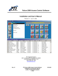
Alarm Connection
on Backboard
AUX2
7
AUX1
GND
6
5
4
3
2
1
ALARMAS
Alarm input 1to 7
Common port
Alarm output 1
Alarm output 2
8
English
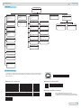
APPENDIX
OSD MAP
MAIN
MENU
SYSTEM SETTING →
CAMERA SETTING →
FUNCTION SETTING →
WINDOW BLANKING →
ALARMS→
EXIT
SYSTEM
SETTING
ADVANCE SETTING
EDIT DOME LABEL
AE
MODE
SHUTTER
IRIS
BRIGHT
WB MODE
R GAIN
B GAIN
HI-RESOLUION
BACK
EXIT
001
LABEL:
BACK
EXIT
PATTERNS
AUTO
ON
ON
005
NONE
NONE
040
OFF
002
020
N/A
→
→
LABEL
ALARM NUMBER
ALARM ACTION
ACTIVATE AUX
ALARM PRIORITY
BACK
EXIT
SCAN
ARM SETTING
001
TOUR
NONE
HIGH
DAY
ARM STATE
ARM TIME
UNARM
BACK
EXIT
SUN
OFF
N/A
N/A
EDIT PATTERN LABEL
1
LABEL: PATTERN-1
BACK
EXIT
TOUR
MOTION
ON
EDIT SCAN LABEL
01
63
PATTERN NUMBER
PROGRAM PATTERN
RUN PATTERN
CLEAR PATTERN
EDIT PATTERN LABEL
BACK
EXIT
TOUR NUMBER
E D I T T O U R→
RUN TOUR
CLEAR TOUR
BACK
EXIT
RESUME
SEQUENCE
RESET DELAY
ALARM CONTACT
ALARM SETTING
ARM SETTING
BACK
EXIT
LABEL: PRESET-01
BACK
EXIT
SCAN
OFF
OFF
OFF
OFF
OFF
OFF
OFF
OFF
PRESET
ALARMS
01
ALARM SETTING
SCAN NUMBER
SCAN SPEED
SET LEFT LIMIT
SET RIGHT LIMIT
CLEAR SCAN
RUN SCAN
E D I T S C A N L A B E L→
BACK
EXIT
DISPLAY SETUP
AUTO FLIP
PROPORTION PAN
PARK TIME
PARK ACTION
POWER UP ACTION
FAN
ENABLED
BACK
EXIT
EDIT
PRESET NUMBER
SET PRESET
SHOW PRESET
CLEAR PRESET
EDIT PRESET LABEL
BACK
EXIT
S/N XXXXXXXXXXXXXXX
FIRMWARE V2.42
PROTOCOL :VIDO B02
DOME ADDRESS: 001
C O M M : 96 0 0 . N . 8 . 1
BACK
EXIT
BLANKING
WINDOW NUMBER
EDIT WINDOW
ENABLE WINDOW
CLEAR WINDOW
BACK
EXIT
PRESETS
AUTO
N/A
N/A
N/A
AUTO
N/A
N/A
OFF
INFO
DOME LABEL
PRESET LABEL
ZOOM LABEL
ZONE LABEL
DIRECTION LABEL
TEMPERATURE
LABEL
TIME LABEL
DATE LABEL
BACK
EXIT
WINDOW
SETTING
PRESETS→
SCAN→
PATTERNS→
TOUR→
ZONES→
TIME RUNNING →
BACK
EXIT
ZOOM SPEED
HIGH
DIGITAL ZOOM
ON
BLC MODE
OFF
SLOW SHUTTER
ON
WDR MODE
IR CUTTER
AUTO
ADVANCE SETTING →
BACK
EXIT
LABEL:
BACK
EXIT
INITIAL
FUNCTION
CAMERA SETTING
EDIT DOME LABEL →
INITIAL INFO →
DISPLAY SETUP →
MOTION →
CLEAR →
PASSWORD SETUP →
CLOCK SETTING →
COMM SETTING →
BACK
EXIT
EDIT T O U R
1
P0-S- TM
00-0- 00
00-0- 00
00-0- 00
00-0- 00
00-0- 00
BACK
EXIT
ZONES
P0-S- TM P0-S- TM
00-0- 00 00-0 - 00
00-0- 00 00-0 - 00
00-0- 00 00-0 - 00
00-0- 00 00-0 - 00
00-0- 00 00-0 - 00
EDIT ZONE LABEL
ZONES NUMBER
SET LEFT LIMIT
SET RIGHT LIMIT
CLEAR ZONE
EDIT ZONE LABEL
BACK
EXIT
1
LABEL: ZONE-1
BACK
EXIT
CLEAR
CLEAR ALL ZONES
CLEAR ALL PRESETS
CLEAR ALL PATTERNS
CLEAR ALL TOURS
CLEAR ALL WINDOWS
FACTORY DEFAULTS
RESTART
BACK
EXIT
TIME RUNNING
TIME CHANNEL
START TIME
END TIME
RUNNING
BACK
EXIT
1
00:00
00:00
NONE
PASSWORD SETUP
OLD PASSWORD : ******
NEW PASSWORD : ******
CONF PASSWORD : ******
ENABLE PASSWORD: OFF
BACK
EXIT
CLOCK SETTING
TIME:
DATE:
BACK
EXIT
00:00:00
08/03/12
COMM SETTING
S/N XXXXXXXXXXXXXXX
CONF: XXXXXXXXXXXXXXX
SITE ID
001
COMM SPEED 9600BPS
PROTOCOL
VIDO B02
BACK
EXIT
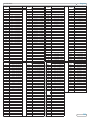
DIP Switch Setting
The Sw1 contains the setting for ID, please refer to next section
for settings. Sw2 contains setting for Protocol, Baud-rate and
Te r m i n a t i o n :
SW2 DIP 1 to 5 : Protocol
ON
B02
ON
ON
Pelco-P/D
ON
ON
ON
SW2 DIP 6 to7 : Baud-Rate
ON
ON
VLC
ERNITEC
ON
ON
ON
MOLYNX
ON
ON
4800
2400
ON
9600
ON
19200
ON
SW2 DIP 8 : Rs485 Termination
VICON
ON
LILIN
SANTACHI
ON
DIAMOND
Panasonic
ON
HUNDA
Samsung
Kalatel
ON
ON
ISD
DYNACOLOR
ON
ON
ON
OFF
Note: VIDO B02 Protocol is fully
compatible with VIDO B01. For previous
version of Vido products please set to B02
ON
KTD410
9
English
APPENDIX
ID
1
2
3
4
5
6
7
8
9
10
11
12
13
14
15
16
17
18
19
20
21
22
23
24
25
26
27
28
29
30
31
32
33
ID
68
69
70
71
72
73
74
75
76
77
78
79
80
81
82
83
84
85
86
87
88
89
90
91
92
93
94
95
96
97
98
99
100
101
Switchnumber (Sw1)
Bit 1 2 3 4 5 6 7 8
00000000
10000000
01000000
11000000
00100000
10100000
01100000
11100000
00010000
10010000
01010000
11010000
00110000
10110000
01110000
11110000
00001000
10001000
01001000
11001000
00101000
10101000
01101000
11101000
00011000
10011000
01011000
11011000
00111000
10111000
01111000
11111000
00000100
10000100
ID
Switchnumber (Sw1)
Bit 1 2 3 4 5 6 7 8
00100010
10100010
01100010
11100010
00010010
10010010
01010010
11010010
00110010
10110010
01110010
11110010
00001010
10001010
01001010
11001010
00101010
10101010
01101010
11101010
00011010
10011010
01011010
11011010
00111010
10111010
01111010
11111010
00000110
10000110
01000110
11000110
00100110
10100110
ID
34
35
36
37
38
39
40
41
42
43
44
45
46
47
48
49
50
51
52
53
54
55
56
57
58
59
60
61
62
63
64
65
66
67
102
103
104
105
106
107
108
109
110
111
112
113
114
115
116
117
118
119
120
121
122
123
124
125
126
127
128
129
130
131
132
133
134
135
Switchnumber (Sw1)
Bit 1 2 3 4 5 6 7 8
01000100
11000100
00100100
10100100
01100100
11100100
00010100
10010100
01010100
11010100
00110100
10110100
01110100
11110100
00001100
10001100
01001100
11001100
00101100
10101100
01101100
11101100
00011100
10011100
01011100
11011100
00111100
10111100
01111100
11111100
00000010
10000010
01000010
11000010
Switchnumber (Sw1)
Bit 1 2 3 4 5 6 7 8
01100110
11100110
00010110
10010110
01010110
11010110
00110110
10110110
01110110
11110110
00001110
10001110
01001110
11001110
00101110
10101110
01101110
11101110
00011110
10011110
01011110
11011110
00111110
10111110
01111110
11111110
00000001
10000001
01000001
11000001
00100001
10100001
01100001
11100001
ID
136
137
138
139
140
141
142
143
144
145
146
147
148
149
150
151
152
153
154
155
156
157
158
159
160
161
162
163
164
165
166
167
168
169
ID
204
205
206
207
208
209
210
211
212
213
214
215
216
217
218
219
220
221
222
223
224
225
226
227
228
229
230
231
232
233
234
235
236
237
Switchnumber (Sw1)
Bit 1 2 3 4 5 6 7 8
00010001
10010001
01010001
11010001
00110001
10110001
01110001
11110001
00001001
10001001
01001001
11001001
00101001
10101001
01101001
11101001
00011001
10011001
01011001
11011001
00111001
10111001
01111001
11111001
00000101
10000101
01000101
11000101
00100101
10100101
01100101
11100101
00010101
10010101
Switchnumber (Sw1)
(Bit)1 2 3 4 5 6 7 8
00110011
10110011
01110011
11110011
00001011
10001011
01001011
11001011
00101011
10101011
01101011
11101011
00011011
10011011
01011011
11011011
00111011
10111011
01111011
11111011
00000111
10000111
01000111
11000111
00100111
10100111
01100111
11100111
00010111
10010111
01010111
11010111
00110111
10110111
ID
170
171
172
173
174
175
176
177
178
179
180
181
182
183
184
185
186
187
188
189
190
191
192
193
194
195
196
197
198
199
200
201
202
203
ID
238
239
240
241
242
243
244
245
246
247
248
249
250
251
252
253
254
255
Switchnumber (Sw1)
Bit 1 2 3 4 5 6 7 8
01010101
11010101
00110101
10110101
01110101
11110101
00001101
10001101
01001101
11001101
00101101
10101101
01101101
11101101
00011101
10011101
01011101
11011101
00111101
10111101
01111101
11111101
00000011
10000011
01000011
11000011
00100011
10100011
01100011
11100011
00010011
10010011
01010011
11010011
Switchnumber (Sw1)
(Bit)1 2 3 4 5 6 7 8
01110111
11110111
00001111
10001111
01001111
11001111
00101111
10101111
01101111
11101111
00011111
10011111
01011111
11011111
00111111
10111111
01111111
11111111
10
English
SPECIFICATIONS
PIC
Model Number
TV System
Image Sensor
Resolution
P-021
SEIMW36T-V53DN
SEMIW36T-V53DNP
NTSC
PAL
1/4” Sony Exview HAD CCD
530 TV Lines / 440,000 Pixels
Video Output
Compound Signal 1.0V p-p, 75 Ohms
Sync System
Internal / External (V-Lock)
White Balance
Minimum Illumination
S/N Ratio
Electronic Shutter
Minimum Illumination
Focal / Iris
Zoom
Iris & Zoom
IR LED
Wavelength
Automatic / Manual
Auto, Manual, Bright, Back Light Compensation
More than 50dB
1/1 ~ 1/10,000s, 22 steps
0 Lux @ IR “on”
3.4mm~122.4mm Lens
36x Optical Zoom / 12x Digital Zoom
Automatic / Manual
36 High Brightness IR LED
850nm
IR Distance
260ft / 80m
Pan Speed
0° ~ 80° per sec.
Tilt Speed
0° ~ 60° per sec.
Preset Positions
128 Presets
Patrol Function
6 Patrol Patterns (Max.)
Scanning Speed
0.5° ~ 30° per sec.
Self Study Pattern
40 sec.
Four Channel Alarm Inputs
Normal Open, Closing for Alarm
One Channel Alarm Output
Normal Open, Normal Close for Output
IP Rating
Power Consumption
Power Supply
Operation Temperature
Humidity
Weight
IP66
30 VA
24V AC
-31°F ~ 122°F / -35°C ~ 50°C
10% ~ 90%
22 lbs / 10,000g
WARRANTY
OKINA USA products are covered under warranty for one year from the date of purchase. The warranty will automatically
be voided if any of the following occurs:
1. Camera sticker is removed
If the camera sticker is removed, we will not be able to confirm any information regarding when and where the product was
purchased. We have no other way to verify the purchase record without the serial number on the camera sticker; therefore,
it should not be removed.
2. Camera is modified in any way
If the camera is scratched, damaged, or modified in a manner not described in this manual, the warranty will be voided
immediately. It is the customer’s responsibility to keep the camera in good condition.
11