1
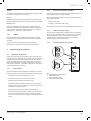
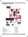
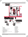
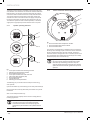
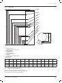
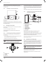
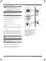
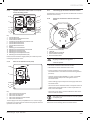
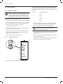
Instructions for use
Installation
and Servicing
Solar Hot Water Cylinders/
Flurocyl2
200
250
300
Table of contents
INT R O D U C T I O N
1
Instructions guidance.................................................................................................................... 3
1.1
1.2
1.3
1.4
1.5
2
Safety instructions and regulations................................................................................................ 3
2.1
2.2
2.3
2.4
2.5
3
Product documentation........................................................................................3
Associated documents ........................................................................................3
Storage of documents..........................................................................................3
Explanation of symbols........................................................................................3
Benchmark..........................................................................................................3
Intended use.......................................................................................................3
General safety information . .................................................................................4
Cylinder safety information...................................................................................4
Cylinder identification plate..................................................................................4
Regulation and statutory requirements..................................................................4
Introducing your appliance............................................................................................................ 5
3.1
Appliance description..........................................................................................5
r e ad c are f ul ly b e for e u sin g
4
Operation..................................................................................................................................... 6
4.1
4.2
4.3
4.4
4.5
5
Adjusting the hot water temperature.....................................................................6
Switching off hot water.........................................................................................6
Frost protection...................................................................................................6
Cleaning the cylinder...........................................................................................6
Fault finding........................................................................................................7
Inspection and Maintenance.......................................................................................................... 7
TECH N I CAL DATA
6
Technical data............................................................................................................................... 8
INSTALLAT I O N
7
Hydraulic and electrical schematics.............................................................................................. 10
8
Description of the components .................................................................................................... 12
8.1
8.2
9
Cylinder installation.................................................................................................................... 13
9.1
9.2
9.3
9.4
9.5
9.6
9.7
10
Flurocyl2 solar cylinder.......................................................................................12
Solar pump safety thermostat.............................................................................12
Cylinder device description.................................................................................13
Installation site..................................................................................................15
Installing of discharge pipe................................................................................15
Pipes for the reheating circuit.............................................................................17
Installing hot water pipes...................................................................................18
Installation of cold water pipe.............................................................................18
Electrical installation..........................................................................................20
Commissioning .......................................................................................................................... 21
10.1 Filling the cylinder.............................................................................................21
-1-
Table of contents
MA I N TE N AN CE
11
Inspection and maintenance........................................................................................................ 23
11.1 Maintenance checklist........................................................................................23
11.2 Draining the cylinder..........................................................................................23
11.3 Fault diagnosis..................................................................................................24
12
Recycling and disposal................................................................................................................ 25
12.1 Cylinder disposal...............................................................................................25
12.2 Disposal of packaging........................................................................................25
13
Customer service and manufacturer's warranty............................................................................. 26
13.1 Glow-worm service.............................................................................................26
13.2 Glow-worm warranty..........................................................................................26
14
-2-
Spare parts................................................................................................................................. 27
INTRODUCTION
INTRODUCTION
1
Instructions guidance
1.1
Product documentation
The instructions are an integral part of the appliance and must be
handed to the user on completion of the installation in order to
comply with the current regulation.
• Carefully read the manual, to understand all the information
to enable safe installation, use and servicing. No liability can
be accepted in the event of damage for not complying with the
guidance in this instruction manual.
1.2
Associated documents
When installing and maintaining the solar system, you must
observe all of the installation and maintenance instructions
for system parts and components as well as those for other
accessories which are used in the system.
These installation and maintenance manuals are provided with
the relevant system parts, components, and accessories.
1.3
Storage of documents
Pass this installation manual and all other applicable documents
and, if necessary, any required aids to the system operator.
The system operator will be responsible for storing them so that
the instructions and aids are available when required.
1.4
Explanation of symbols
installed, commissioned and serviced in accordance with the
manufacturer’s instructions by competent persons and that it
meets the requirements of the appropriate Building Regulations.
The Benchmark Checklist must be used to demonstrate
compliance with Building Regulations and must be provided to
the customer for future reference.
Installers are required to carry out installation, commissioning
and servicing work in accordance with the Benchmark Code
of Practice which is available from the Heating and Hotwater
Industry Council who manage and promote the Scheme.
• Visit www.central heating.co.uk for more information.
2
2.1
Safety instructions and regulations
Intended use
Glow-worm cylinders are constructed using state-of-the-art
technology in accordance with recognised safety regulations.
Nevertheless, there is still a risk of injury or death to the user or
others or of damage to the unit and other property in the event of
improper use or use for which the unit is not intended.
Glow-worm cylinders are not intended for use by persons who
have inadequate experience and/or knowledge, unless they are
supervised by a person responsible for their safety or have been
given instructions by this person regarding the operation of the
unit. Children must be supervised to ensure that they do not play
with the unit.
Glow-worm Flurocyl2 domestic hot water cylinders are unvented,
indirectly heated domestic hot water cylinders designed for use
with gas-fired boilers as per GB standards for hot water supply
systems. The cylinders work with the pressure of the water supply
line and do not need a cold water tank for their supply.
a
DANGER: Risk of injuries.
They are used only to supply potable water heated up to 80°C
in solar systems with a collector array. They may only be used
for this purpose. The cylinders can be used in combination
with a downstream gas-fired boiler for hot water generation in
accordance with GB standards.
e
DANGER: Risk of electric shock.
Any other use or extended use is considered to be improper.
Improper use of any kind is prohibited.
ATTENTION: Risk of damage to the appliance or to its
vicinity.
IMPORTANT: Useful information.
1.5
Benchmark
The manufacturer/supplier is not liable for any damage resulting
from improper use. The user alone bears the risk. Intended use
also includes observing the operating and installation manuals
and all other applicable documents, as well as complying with the
inspection and maintenance conditions.
At the end of this manual there is a commissioning report which
you must fill in and hand over to the operator. All installers
should have a current ID card and registration number. The
cylinder must be installed by a competent person approved at
the time by the Health and safety Executive to the prevailing
standards, installation book and building regulations at the time
of installation.
Benchmark places responsibilities on both manufacturers
and installers. The purpose is to ensure that customers are
provided with the correct equipment for their needs, that it is
0020115479_03 - 10/12 - Glow-worm
-3-
INTRODUCTION
2.2
General safety information
2.3.3
Avoiding damage caused by leaks
Installation and adjustment as well as service, maintenance
and repair must be carried out by a competent person approved
at the time by the Health and Safety Executive and be in
accordance with the relevant requirements of the Local Authority,
Building Regulations, Building Regulations (Scotland), Building
Regulations (Northern Ireland), and the bye-laws of the local
Water Undertaking.
If there are leaks in the pipe network, close off the cold water stop
valve on the safety assembly and notify an engineer qualified to
work on unvented systems to rectify the leaks.
2.3
If the system is in stagnation then hot steam can discharge from
the expansion relief valve of the solar pump unit. This may be
visible in the receptor canister. Should this occur contact your
installer for advice.
Cylinder safety information
This product has been assessed and found to comply with the
requirements of the Building Regulations for unvented hot water
storage systems and must not be altered or modified in any way.
In the event of parts replacement, use only genuine spare parts
supplied by Glow-worm.
The installation is subject to Building Regulation approval.
Notify the Local Authority of intention to install.
As stipulated in the manual "Handling Operations
Regulations 1992", the weight of the unit exceeds that
which should be lifted by one person.
Without potential equalisation, life-threatening voltage from
the electric immersion heater can reach the piping and water
taps.Earth the electric immersion heater. If the solar cylinder is
connected with pipes made of non-metallic materials and is not
earthed, corrosion damage can occur.
2.3.4
Avoiding burns and scalds
For scald protection, install a hot water thermostat mixer in the
system.
The temperature of the stored water could reach high
temperatures after solar charging and your Glow-worm solar
installer will have fitted a tempering valve so as to prevent this
reaching the hot water taps. Should excessively hot water reach
your hot taps contact your installer immediately.
2.3.5
Preventing damage due to unauthorised
changes to the unit
Changes to the supply lines, relief valve termination, and
expansion relief valve may only be carried out by an engineer
qualified to work on unvented systems.
Never shut off the expansion relief valve or relief valve
termination.
Earth the solar cylinder for potential equalisation and to protect
against overvoltage.
If using non-metallic pipes on the water route, make sure that
they are designed by the manufacturer for continuous operation
at 70°C and operation by the hour at temperatures of up to 95°C
Always use a suitable open-end spanner to tighten or undo
threaded connections. Do not use pipe wrenches, extensions,
etc. If the water does not meet the requirements of the UK water
quality standards with a maximum chloride level of 250 mg/l,
corrosion damage may occur to the cylinder.
Only use the cylinder to heat potable water.
2.3.1
Electric potential equalisation
If you use an electric immersion heater in the cylinder, the
external voltage may build up electrical potential in the water
which can result in the electrochemical corrosion of the electric
immersion heater. Make sure that both the hot water and cold
water pipes are connected to the earth line by means of earth
cable directly on the cylinder. You must also make sure that the
electric immersion heater is connected to the earth line via the
earthing terminal.
2.3.2
Preventing frost damage
You should not turn the gas-fired boiler off completely so that
you can still use all of the safety functions for your heating
installation. If you want to take the unit out of operation for a
relatively long period of time in an unheated room at risk from
frost, you must completely drain the Flurocyl2.
-4-
Never bypass any of the security devices.
2.4
Cylinder identification plate
The identification plate is attached to the middle of the cylinder
at the factory.
2.5
2.5.1
Regulation and statutory requirements
Cylinder and cylinder assembly
Pressure equipment directive 97/23/EC
Directive of the European Parliament and Council from 29th May,
1997 for the approximation of the laws on pressure equipment of
the Member States
EN 12977-3
Thermal solar systems and components; Custom built systems,
Part 3: Performance characterisation of domestic hot water
cylinders
EN 12897:2006
Water supply - specification for indirectly heated unvented
(closed) domestic hot water cylinders
0020115479_03 - 10/12 - Glow-worm
INTRODUCTION
EN 806-1
3.1.2
Specifications for installations inside buildings conveying water
for human consumption - Part 1: General
You can set the hot water temperature and reheating times in the
upper half of the cylinder on the controller.
EN 1717
One of the following controllers may be used depending on the
design of your system:
Protection against pollution of potable water installations and
general requirements of devices to prevent pollution by backflow
Hot water temperature regulation
-- Glow-worm Fluropro
EN 60335-2-21
-- Climapro2 in conjunction with a timer
Safety of household and similar electrical appliances; Part 2:
Particular requirements for storage water heaters (domestic hot
water cylinders and hot water boilers) (IEC 335-2-21: 1989 and
supplements 1; 1990 and 2; 1990, modified)
Refer to the operating manual for the installed controller or timer.
2.5.2
CE Mark
CE labelling shows that the appliance according to the model
overview comply with the basic requirements of the applicable
directives.
The CE declarations of conformity can be viewed at the
manufacturer's premises and can be supplied if necessary.
3.1.3
Electric immersion heater
The cylinder is equipped with an additional electric immersion
heater (3) with a heating output of 3 kW. The electric immersion
heater is designed for use in unvented cylinders and has a
thermostat with a temperature controller (2) and a safety
thermostat (TCO) with a reset button (1).
3.1.4
Functional elements of cylinder
1
3
Introducing your appliance
2
3
3.1
Appliance description
The Flurocyl2 solar cylinder is available in three sizes: 200, 250
and 300 litres. The containers are made from stainless steel with
EPS with additional infared absorbing insulation. The cylinder
works with the pressure of the water supply line and does not
need a cold water tank for its supply. To enable the cylinder to
work as well as possible, a cold water supply with an appropriate
pressure and flow rate is required.
3.1.1
4
Safety devices
The solar cylinder has been provided with all safety and control
devices for operation of the unvented domestic hot water supply:
-- Temperature/pressure relief valve (90 °C, 7 bar)
-- Pressure limiting valve (3.5 bar) with line strainer
Key
1 Reset button for reheating circuit
2 Cylinder thermostat
3 Electric immersion heater
4 Reset button for solar circuit
-- Expansion relief valve (one-way valve, 6.0 bar)
-- Solar pump safety thermostat, set to 80 °C, connected with
the solar pump in order to isolate this heat source if there is a
malfunction in the solar control.
-- Safety thermostat for electric immersion heater (85 °C).
-- Solar cylinder safety thermostat, set to 80 °C, to be connected
to the 2-port motorised valve in order to isolate the primary
heat source if a domestic water supply thermostat malfunction
occurs.
0020115479_03 - 10/12 - Glow-worm
-5-
read carefully before using
4
Operation
a
a
Always make sure that there is clear access to the
cylinder to enable the use of the hot water thermostat
controller and the thermostat mixer.
Risk of scalding and bursts due to inappropriate
alterations!
There is a risk of escaping steam, bursting, and
damage to the system if you make any changes to
the cylinder, control system, supply lines for water
and power (if present), relief valve termination, or
expansion relief valve for the cylinder water.
4.2
Do not make any improper changes.
4.3
• Switch off the immersion heater and the gas-fired boiler (see
the operating manual for the gas-fired boiler) to temporarily
switch off the heating and hot water system.
Frost protection
Risk of scalding!
Risk of damage due to frost!
The output temperature of the draw-off points can
reach 85 °C if the mixing valve is set incorrectly.
If the cylinder is placed out of operation for a
relatively long period of time in an unheated room
(e.g. during a winter holiday), the cylinder must be
completely drained.
- Do not adjust the mixing valve.
- If the output temperature at a draw-off point is too
high or low, Contact an engineer qualified to work on
unvented systems to adjust the temperature.
4.1
Switching off hot water
Adjusting the hot water temperature
The hot water temperature is set to the required value by the
engineer qualified to work on unvented systems during the
cylinder commissioning. If an external controller is installed
for hot water temperature control, you can adjust the hot water
temperature and reheating times using this controller.
For information on making settings, see the operating manual for
the controller.
If no controller for hot water temperature control is installed,
you can set the required hot water temperature on the cylinder
thermostat (2). You can set the reheating times on the installed
hot water timer. Refer to the operating manual for the hot water
timer.
- Contact an engineer qualified to work on unvented
systems to drain the cylinder.
If you are absent during a relatively long period when there is a
risk of frost, make sure that you leave the central heating on and
that the temperature in the cylinder room and in all other rooms
are kept above freezing.
4.4
Cleaning the cylinder
• Clean the outside of the cylinder only with a damp cloth, using
soapy water if it is especially dirty.
Do not use abrasive cleaning agents or solvents (any type of
scouring agent, petroleum etc.) since they can damage the
cladding and the cylinder fixtures.
• Set the desired cylinder hot water temperature on the cylinder
thermostat (2).
• For optimum efficiency, choose a setting of 45 °C.
• Use the operating manual for the gas-fired boiler to make sure
that the unit is ready for operation.
We recommend the cylinder is set to 60 °C
periodically, to provide protection against the
proliferation of harmful bacteria.
If you are heating up water for the first time or after a
long switch-off period, the full cylinder performance is
only available following a waiting period.
If the Flurocyl2 is installed in a cupboard, make sure
that clothing and other objects are not placed on
the cylinder, control devices, pipes, or other system
components.
-6-
0020115479_03 - 10/12 - Glow-worm
read carefully before using
4.5
Fault finding
Fault
Remedy
Fluid is dripping from the system?
If possible, collect the fluid in a bucket and contact an engineer qualified to
work on unvented systems.
The controller issues a message telling me the sensor is faulty or
there is a cable break?
Contact an engineer qualified to work on unvented systems.
The cylinder is not providing sufficient hot water?
Check that the hot water temperature is set correctly on the controller
(recommended value of approx. 45 °C, however, set periodically to 60 °C to
provide protection against the proliferation of harmful bacteria) and
that the gas-fired boiler is working. If the settings are
correct, the cylinder may be calcified. Then: contact an engineer qualified to
work on unvented systems.
A safety thermostat trips?
Contact an engineer qualified to work on unvented systems.
Water escapes from the expansion relief valve?
Contact an engineer qualified to work on unvented systems.
5
Inspection and maintenance
An annual inspection/maintenance run by an engineer qualified
to work on unvented systems is a prerequisite for ensuring that
the cylinder is permanently ready for operation, reliable, and has
a long service life.
It is important that your hot water cylinder is serviced annually.
We recommend entering into a maintenance agreement.
After servicing, the servicing engineer must complete the relevant
Service Interval Record section of the Benchmark Checklist
located on the inside back pages of this document.
e
Risk of death from electric shock.
Improperly executed work on the cylinder can result in
a risk to life and limb.
- Never try to rectify cylinder malfunctions yourself.
- Contact an engineer qualified to work on unvented
systems to rectify all malfunctions.
a
Risk of injury resulting from improper maintenance or
repair.
Failure to arrange for the system to be maintained
and repaired and improper maintenance and repair
can impair the operational safety of the unit, leading
to injuries and damage to property
- Never attempt to perform maintenance work or
repairs on the cylinder yourself.
- Always employ an engineer qualified to work on
unvented systems.
0020115479_03 - 10/12 - Glow-worm
-7-
technical data
TECHNICAL DATA
6
Technical data
Unit
Flurocyl2 200
Flurocyl2 250
Flurocyl2 300
Total capacity
l
200
250
300
Actual capacity
l
209.4
254.4
297.2
Hot water capacity (upper coil)
l
104.8
142
144.2
Hot water capacity (solar coil)
l
203.3
246.1
271.1
Dedicated solar volume
l
104.6
112.4
153.0
Maximum supply pressure to pressure reducing valve
bar
12
Maximum operating pressure of cylinder
bar
7
Maximum operating pressure of heating coil
bar
3.5
Maximum operating pressure of solar coil
bar
6
Operating pressure
bar
3.5
Pressure limiting valve
bar
3.5
Expansion relief valve
bar
6.0
Temperature and pressure relief valve
bar
7.0
Charge pressure of hot water expansion vessel
bar
4.0
Maximum temperature of heating circuit
oC
85
Maximum temperature of potable hot water
oC
85
Maximum temperature of solar fluid
oC
85
Standing heat loss
kW/24h
2.05
2.20
2.40
Heat up time according to EN 12897
mins
22
29
30
Recovery time (70% capacity)
mins
16
21
22
Primary heat exchanger performance
kW
14.9
15.3
15.0
Flow rate for primary heat exchanger performance
l/min
23.3
23.3
23.3
Primary heat exchanger pressure drop
mbar
79
78
79
Primary heat exchanger volume
l
2.37
2.37
2.37
Primary heat exchanger surface area
m2
0.5
0.5
0.5
Solar heat exchanger performance
kW
18.7
18.5
16.5
Flow rate for solar heat exchanger performance
l/min
23.3
23.3
23.3
Solar heat exchanger pressure drop
mbar
97
95
98
Solar heat exchanger volume
l
2.94
2.94
2.94
Solar heat exchanger surface area
m2
0.62
0.62
0.62
Heat up time according to EN12897 (solar)
mins
34
42
51
Temperature and pressure relief valve
oC/bar
90 / 7.0
Dimensions
Height
mm
1593
1843
2153
Height with hot water draw off
mm
1625
1875
2185
Topple measure
mm
1680
1918
2217
Diameter
mm
554.5
Depth
mm
624
Net weight
kg
40
43
50
Weight (filled)
kg
249
298
347
Connections
Cold water inlet
22mm compression joint
Hot water draw-off
22mm compression joint
Balanced pressure cold water outlet
22mm compression joint
Secondary return
15 mm compression joint
-8-
0020115479_03 - 10/12 - Glow-worm
technical data
Unit
Flurocyl2 200
Flurocyl2 250
Flurocyl2 300
Primary heater flow
22mm compression joint
Primar heater return
22mm compression joint
Solar flow
22mm compression joint
Solar return
22mm compression joint
Primary heating circuit immersion sleeve size
mm
8
Solar circuit immersion sleeve size
mm
8
Electrical data
Immersion heater (according to ENBS 60335)
Length of immersion heater
2.7 kW / 230 V / 50 Hz
inch
14
Two port motorised valve
230/240 V, 50 Hz
Thermal cut out solar
230/240 V, 50 Hz
Cylinder thermostat
230/240 V, 50 Hz
Material data
Cylinder body material
Stainless Steel (1.4521)
Cylinder jacket material
Polypropylene
Insulation material
EPS with infrared absorber
Insulation thickness
50
Corrosion protection
Blowing agent for insulation material
ODP
Stainless Steel
Pentane (GWP < 5)
0
The heat up time is based on a flow rate of 1400 l/h at
80 °C. Temperature rise from 15 °C to 60 °C.
0020115479_03 - 10/12 - Glow-worm
-9-
INSTALLATION
INSTALLATION
7
Hydraulic and electrical schematics
4
3
8
230V
16A
5
6
10
9
11
D
7
12
7.1
13
14
2
7.2
15
E F
16
1
7.3
C
G
17
18
20
H
A
19
B
9
10
230V~
PCSA
PCSB/PC LEG/BYP
R
230V
16A
N
L
11
3A
V3V
CH
4
6
3A
13 16
12
2
C
2 1
7
C
2
L
L link
Bl Gr Or
R
R
N L 3 4 5 6 7 8 9 10
C
N
3A
Load
3A
Key:
1Boiler
2Solar gain NTC
3Solar collector
4 Collector NTC
5Solar expansion vessel and protection vessels
6 Solar pump station
7 Domestic hot water cylinder
7.1 Cylinder dual thermostat
7.2 Immersion heater with thermal safety
7.3Solar pump thermal cut-out
8Additional terminal block
9Electrical supply + protection (This must have it's own single
isolation)
10Fluropro solar controller
11 CH time controller
- 10 -
R
230V
N L
10
C
R1
1
7.3
2
Or
2
7.1
C
Bl Gr
14
N L L link
R
Bl Gr Or
R
7.2
8
18
19
7
1
15
12Electrical switch
13 NTC sensor pocket (TAC 2)
14 Terminal block
15 Room thermostat
16 NTC sensor (TAC 2)
17 Heating circuit
18 DHW 2 port valve
19 CH 2 port valve
ABoiler circuit return
B Boiler circuit flow
C Cold water supply
D Domestic hot water outlet
E Cylinder circuit flow
F Cylinder circuit return
GSolar circuit return
H Solar circuit flow
0020115479_03 - 10/12 - Glow-worm
INSTALLATION
4
3
8
5
6
9
230V
16A
10
D
7
11
12
EBUS
7.1
2
13
14
7.1
1
F E
15
7.2
C
16
17
19
G
H
A
18
B
9
230V~
PCSA
PCSB/PC LEG/BYP
R
230V
16A
V3V
10
2 1
14
4
6
3A
13 15
12
2
230V~
CYL.
DHW
CH
BUS
DHW
On Off On
On
+ –
NTC
+ –
7.1
8
2 1
N L
N L
N L L link
C
3A
2
1
18
17
BUS
7.2
N L
C
2
L
L link
16A
20
Key:
1Ebus boiler
2Solar gain NTC
3Solar collector
4 Collector NTC
5Solar expansion vessel and protection vessel
6 Solar pump station
7 Domestic hot water cylinder
7.1 Immersion heater with thermal safety
7.2 Cylinder overheat thermostat
7.3Solar pump thermal cut-out
8Additional terminal block
9Electrical supply + protection (This must have it's own single
isolation)
10Fluropro solar controller
11 Climapro RF
0020115479_03 - 10/12 - Glow-worm
BUS
12Electrical switch
13 NTC sensor (TAC 1)
14Smart Wiring Center
15 NTC sensor (TAC 2)
16 Heating circuit
17 DHW 2 port valve
18 CH 2 port valve
19Automatic air separator
20 RF receiver
ABoiler circuit return
B Boiler circuit flow
C Cold water supply
D Domestic hot water outlet
E Cylinder circuit flow
F Cylinder circuit return
GSolar circuit return
H Solar circuit flow
- 11 -
INSTALLATION
8
Description of the components
8.1
Flurocyl2 solar cylinder
Section 4.1 of this manual describes the Flurocyl2 solar cylinder
in detail.
8.2
Solar pump safety thermostat
1
3
3
2
3
4
3
Fig. 4.1 Connection diagram for solar pump
Key
1Solar controller or solar module
2 Terminal strip
3Solar pump
4Solar circuit safety thermostat
In order to meet the requirements for unvented hot water cylinder
systems (G3), you must connect the power supply for the solar
pump (3) via a manually resettable safety thermostat (TCO) in the
solar cylinder.
The Flurocyl2 solar cylinder is fitted with an appropriate safety
thermostat (4) at the factory. If the cylinder temperature is higher
than 80 °C, the safety thermostat interrupts the power supply to
the solar pump.
8.2.1
Cylinder frost protection
If you want to put a cylinder out of operation where it may be
at risk from frost, you must drain it completely. It is drained at
the cold water inlet with a T-piece with tap to be provided by the
installer.
Any heat exchangers not filled with solar fluid in rooms which are
at risk of frost must also be completely drained.
- 12 -
0020115479_03 - 10/12 - Glow-worm
INSTALLATION
9
Cylinder installation
9.1
Cylinder device description
1
26
2
3
25
21
22
24
4
23
7
20
5
9
19
18
6
8
3
17
16
15
14
13
12
10
11
Key
1 Hot water connection
2Expansion relief valve (one-way valve, 6.0 bar)
3 Pressure limiting valve (3.5 bar) with line strainer
4 Cold water connection
5 Pressure-controlled cold water connection
6 Connection for hot water expansion vessel
7 Cylinder connection
8 Hot water expansion vessel
9 Tundish
10 Cylinder drain valve (not supplied)
11 Return line (solar circuit)
12Solar collector temperature sensor
13 Cold water pipe
14 Solar circuit safety thermostat (TCO), set to 80 °C, to be connected
with the solar pump in order to isolate this heat source
if there is a malfunction in the solar control.
15 Solar circuit immersion sleeve (length 70mm dia. 8mm) (TAC 2)
16 Supply line (solar circuit)
0020115479_03 - 10/12 - Glow-worm
17 2‑ pole circuit breaker for electric immersion heater
18 Electric immersion heater with thermostat and safety thermostat
(20°C to 65 °C) (length 70mm dia. 8mm)
19 Return line (gas-fired boiler)
20 Reheating circuit immersion sleeve (TAC 1)
21 Reheating circuit safety thermostat, set to 80 °C, to be connected
to the 2-way motorised valve in order to isolate the primary
heat source if a malfunction occurs.
22 Cylinder thermostat (25 °C to 65 °C)
23 2 -way motorised valve
24 Supply line (gas-fired boiler)
25 Circulation line connection
26 Temperature and pressure relief valve (90 °C, 7 bar)
- 13 -
INSTALLATION
The Flurocyl2 solar cylinder is available in three sizes: 200, 250,
and 300 litres. The containers are made from stainless steel with
EPS insulation. The cylinder is supplied along with all required
cold and hot water control devices and a 2-way motorised valve.
The cylinder works with the pressure of the water supply line
and does not need a cold water tank for its supply. The cylinder
has hot and cold water connections with a diameter of 22 mm.
To enable the cylinder to work as well as possible, a cold water
supply with an appropriate pressure and flow rate is required.
9.1.1
Cylinder operating elements
9.1.2
Electric immersion heater operating elements
1
2
4
3
2
3
5
1
1
8
7
2
3
6
Key
1Electric immersion heater temperature controller
2 Electric immersion heater TCO reset button
3Electric immersion heater
The cylinder is equipped with an additional electric immersion
heater (3) with a heating output of 3 kW. The electric immersion
heater is located behind the top front cladding. The electric
immersion heater is designed for use in unvented cylinders and
has a thermostat with a temperature controller (2) and a safety
thermostat (TCO) with a reset button (1).
5
4
If you need to make a replacement, you must use
the correct electric immersion heater with a safety
thermostat for overheating protection. Only use
original replacement parts from Glow-worm. Always
replace the immersion heater gasket when parts are
replaced.
Key
1 Cover cap for reset button for reheating circuit TCO
2 Reheating circuit temperature controller
3 Electric immersion heater cover
4 Cover cap for reset button for solar circuit TCO
5 Solar circuit safety thermostat (TCO)
6 Electric immersion heater
7 Cylinder thermostat
8 Reheating circuit safety thermostat
The following are pre-mounted at the factory for the Flurocyl2
solar cylinder:
Cylinder thermostat (7) and reheating circuit safety thermostat (8)
Electric immersion heater (6) with safety thermostat and cylinder
thermostat
Solar circuit safety thermostat (5)
The cylinder must be properly wired in order to comply with G3
building regulations.
You must connect the solar pump to the solar
controller via the solar circuit safety thermostat.
The thermostat switches the solar pump off if the
temperature of the hot water in the cylinder exceeds
80 °C.
- 14 -
0020115479_03 - 10/12 - Glow-worm
INSTALLATION
9.1.3
Safety devices
The cylinder is delivered with all safety and control devices for the
operation of the unvented domestic hot water supply:
-- Temperature/pressure relief valve (90 °C, 7 bar)
9.2
Installation site
Place the cylinder in a suitable location in the building, paying
attention to the following:
-- Pressure limiting valve (3.5 bar) with line strainer
-- Expansion relief valve (one-way valve, 6.0 bar)
-- Solar circuit safety thermostat, set to 80 °C, to be connected
with the solar pump in order to isolate this heat source if there
is a malfunction in the solar control.
-- Safety thermostat for electric immersion heater (set to 85 °C).
-- Reheating circuit safety thermostat, set to 80 °C, to be
connected to the 2-way motorised valve in order to isolate
the primary heat source if a cylinder thermostat malfunction
occurs.
-- Do not bypass the thermal cut-outs or other saftey devices in
any circumstances
9.1.4
Make sure the cylinder is stored in an upright position in a dry
environment prior to its installation.
-- The tundish discharge pipe must be installed with a minimum
slope of 1:200 and must end in a safe and visible place.
-- The installation surface must be flat and capable of bearing
the weight of the entire cylinder and associated controls when
full of water.
-- The installation site must not be at risk of frost. If necessary,
install a frost protection thermostat.
-- The control system for the installed cylinder thermostat must
be easily accessible to the operator.
-- There must be sufficient space for the assembly, check and
pressure build-up of the expansion vessel.
-- There must be sufficient space for the assembly, check and
maintenance of the immersion heater.
Pack contents
Check the contents of the enclosed box.
-- The floor must be even.
8
a
7
6
1
Where cylinders are fitted high up in the building
there are some situations where a vacuum could be
created in the cylinder. The installer must consider
in these circumstances the necessity of fitting an
anti vacuum valve to prevent cylinder damage.
This valve allows air to enter the cylinder if the
pressure becomes too low due to draining or thermal
contraction.
5
9.3
Installation of discharge pipe
4
9.3.1
3
a
2
Item
Quantity
Component
1
1
Flurocyl2 solar cylinder in separate packaging
2
1
Safety assembly (pressure limiting valve,
expansion relief valve, connections for
pressure-controlled cold water connection
and hot water expansion vessel)
3
1
2-way motorised valve
4
1
15mm compression cap for secondary return
5
1
Tundish
6
1
Assembly set for hot water expansion vessel
7
1
Hot water expansion vessel:
18 l for Flurocyl2 200
25 l for Flurocyl2 250, 300
8
1
Instructions for use, Installation and Servicing
manual
0020115479_03 - 10/12 - Glow-worm
Design of discharge pipe
Risk of burns and scalds resulting from escaping hot
water.
If there is a malfunction, hot water will discharge from
the TPRV via the tundish.
- Lay the discharge pipe so that it ends at an easily
visible point inside or outside the building where
escaping hot water does not pose a risk to persons.
- 15 -
INSTALLATION
9.3.2
Discharge requirements (G3 building
regulations)
SAFETY DEVICE
(E.G. TEMPERATURE
RELIEF VALVE
METAL DISCHARGE PIPE FROM
VENTIL)
TEMPERATURE RELIEF VALVE
600 M
TO TUNDISH
M
TUNDISH
300 MM
MINIMUM
DISCHARGE
BELOW
FIXED
GRATING
FIXED
GRATING
METAL DISCHARGE PIPE
FROM TUNDISH WITH
CONTINUOUS FALL
From Sizing Table:
Maximum resistance allowed for a straight length of 22 mm
copper discharge pipe from a G1/2 temperature relief valve is:
9.0 m.
Subtract the resistance for 4 No. 22 mm elbows at 0.8 m each =
3.2 m.
Therefore the maximum permitted length equates to: 5.8 m,
which is less than the actual length of 7 m therefore calculate the
next largest size.
Maximum resistance allowed for a straight length of 28 mm pipe
from a G1/2 temperature relief valve is: 18 m.
Subtract the resistance of 4 No. 28 mm elbows at 1.0 m each =
4.0 m.
Therefore the maximum permitted length equates to: 14 m.
As the actual length is 7 m, a 28 mm copper pipe will be
satisfactory.
TRAPPED GULLY
The discharge connections of the temperature/pressure relief
valve and the expansion relief valve must be connected with
the supplied tundish via 15 mm copper piping. The tundish
should be attached so that it is vertical, as near to the cylinder
as possible, and not more than 600 mm from the connection
of the temperature/ pressure relief valve. It must be mounted
in the same room as the cylinder at a sufficient distance from
the electrical components. The discharge pipes from the
temperature/pressure relief valve and expansion relief valve can
be joined above the tundish using a T-piece.
The discharge pipe from the 22 mm connection of the drain
funnel must be laid using copper piping with a diameter of at
least 22 mm to a safe and visible discharge point.
A suitable place for the end of the discharge pipe is, for
example, beneath a fixed grille above the odour seal in a gully
with a siphon. Low discharge pipes, for example up to 100 mm
above external surfaces such as car and other parking spaces,
grasslands etc. can be used provided that they are secured by a
wire fence or something similar to prevent children from coming
into contact with the waste water and as long as the system is
not visible. You must not install any valves or stop cocks in the
discharge pipe.
• Make sure that the discharge pipe from the tundish to the
drain has a constant downward incline of at least 1:200. The
discharge pipe from the pressure relief valve of the Glow-worm
gas-fired boiler can be connected to the horizontal discharge
pipe of the cylinder behind the tundish using a T-piece.
There must be a vertical section of pipe at least 300 mm long
beneath the tundish before any bends or elbows in the pipework.
If the total resistance of the discharge pipe exceeds the values
specified in table below, you must increase the diameter of the
piping. When installing the discharge piping, you must observe
Directive G3 (section 2.5).
9.3.3
Sizing of copper discharge pipe for G1/2
temperature and pressure relief valve outlet size
Minimum diameter of
discharge pipe from
tundish
Maximum
permissable total
resistance, expressed
as straight pipe
length (without
elbows or bends)
Resistance due to
each elbow or bend
22 mm
Up to 9 m
0.8 m
28 mm
Up to 18 m
1.0 m
35 mm
Up to 27 m
1.4 m
Worked example
The example below is for a G1/2 temperature relief valve with
a discharge pipe having 4 No. 22 mm elbows and length of 7 m
from the tundish to the point of discharge.
- 16 -
0020115479_03 - 10/12 - Glow-worm
INSTALLATION
9.3.4
Dimensions
1
2
3
4
5
6
7
9
b
a
8
c
10
k
624
j
i
Ø 554,5
h
g
f
e
d
11
25°
l
45°
Key
1 Hot water draw off
2 Temperature and pressure relief valve
3 Secondary return
4 Primary heater flow
5 Immersion sleeve
6 Primary heater return
7 Electric immersion heater
8 Solar flow
9 Solar circuit immersion sleeve (TAC 2)
10 Cold mains inlet
11 Solar return
Flurocyl2
a
b
c
d
e
f
g
h
i
j
k
l
200
1625
1593
1341
1158
1052
912
822
802
534
506
259
51
250
1875
1843
1591
1346
1102
962
872
852
534
506
259
51
300
2185
2153
1901
1578
1377
1237
1147
1127
534
506
259
51
9.4
Pipes for the reheating circuit
Make sure that the pipes between the gas-fired boiler and
cylinder are as short as possible in the reheating circuit. Use
copper piping with a minimum diameter of 22 mm.
0020115479_03 - 10/12 - Glow-worm
- 17 -
INSTALLATION
If you are using the cylinder with a gasfired boiler as per GB
standards, you may have to install a suitable heating pump in the
reheating circuit.
9.4.1
Installing the 2-way motorised valve
In a thermal solar system, a hot water thermostat mixer must
be installed as scald protection. The hot water thermostat mixer
mixes the hot water from the cylinder with cold water to produce
water with a maximum temperature of between 30 and 60 ºC as
required.
The hot water thermostat mixer must be provided by the installer.
1
9.5.2
Installing the hot water thermostat mixer (with
secondary circulation line)
3
2
4
230
1
The 2-way motorised valve prevents the cylinder from
overheating.
Install the 2-way motorised valve (1) supplied with the cylinder in
the supply line of the gas-fired boiler. Do not install the valve with
the head upside down.
9.5
Installing hot water pipes
Connect the hot water piping to the 22 mm hot water connection
of the cylinder.
Lay the 22 mm piping up to the first T‑piece.
The required diameter of subsequent pipes depends on the
system design.
9.5.1
Connecting up the secondary circulation line
1
7
6 5
8
9
10
Key:
1 Non-return valve
2 Hot water thermostat mixer
3 Solar controller
4 Hot water pipe
5 Circulation line
6 Circulation pump
7 Contact thermostat
8 Expansion relief valve
9 Cold water pipe
10 Solar cylinder
Where possible, avoid installing a circulation line, since a
circulation line results in higher energy consumption.
The cylinder has a connection with a 15 mm diameter for a
circulation line.
If the installation of a circulation line is required, keep circulation
operations to a minimum by only using circulation mode when
required for demand and temperature reasons.
• Connect a WRAS-approved circulation pump which has a nonreturn valve with the circulation connection.
Connect the circulation line (6) to the hot water pipe (4) via a hot
water thermostat mixer (2).
• Establish the connection to the circulation line.
If you are not using the secondary circulation
connection, you must ensure that it is properly closed
off. Where secondary return circuits are used, an
additional expansion vessel may be required.
1
AB
A
9.6
Installation of cold water pipe
The efficiency of an unvented cylinder depends on the available
pressure in the cold water pipe and the flow rate. To obtain
maximum cylinder efficiency, there must be a suitable cold water
pipe, i.e. the measured static line pressure must be at least 2.0
bar. A corresponding flow rate of at least 20 - 25 l/min must be
available.
The pressure in the cold water pipe will be reduced
at times of high consumption. Thus, measurements
should be taken at such times.
The cylinder still works satisfactorily with a pressure below 2 bar
but the flow rate is reduced. If the pressure is below 1 bar, you
should not install an unvented cylinder.
Key:
1 Thermostat mixer
A Hot water
B Cold water
AB Mixed water
- 18 -
B
Glow-worm can provide information on alternative hot water
supply systems.
0020115479_03 - 10/12 - Glow-worm
INSTALLATION
9.6.1
Flurocyl2 hot water flow rates at 60 °C
Risk of damage to the cylinder as a result of excess
pressure! Excess pressure can cause the cylinder to
burst. Make sure that the expansion relief valve outlet
is not covered or closed.
-- Mount the discharge pipe of the expansion relief valve with
a constant slope to the outside. The discharge pipe must
finish at a safe and visible point where there is no danger of it
freezing up and where it poses no risk of injury to persons.
80
Flowrate (l/min)
60
-- Actuate the expansion relief valve regularly to prevent
calcification.
40
-- Connect the cylinder to the cylinder connection (4).
-- For the pipe from the main stop valve of the building to the
cylinder, use copper piping with a diameter of at least 22 mm
to ensure that the cylinder is as efficient as possible. This
is particularly important for installations with a pressurecontrolled cold water connection (3).
20
0
1
2
3
4
Inlet pressure (bar)
-- Mount a drain valve in the cold water pipe at the lowest point
between the cylinder and the safety assembly.
5
The displayed flow rates apply to installations in which the cold
water supply is of appropriate dynamic pressure. If the static
water pressure is less than 1 bar, contact Glow-worm.
9.6.2
If you mount the safety assembly above the cylinder,
you do not need to drain the cylinder in order to
maintain the safety assembly. Make sure there is
sufficient space for maintenance and the connection of
the discharge pipe from the expansion relief valve.
Mounting the safety assembly
Risk of damage to the cylinder as a resultof excess
pressure! Excess pressure can cause the cylinder to
burst. Make sure that there is no stop valve installed
between the safety assembly and the cylinder.
9.6.3
-- Mount the safety assembly in the cold water pipe on the
cylinder.
Safety assembly
7
When the discharge pipes are connected, the expansion relief
valve may not be more than 600 mm away from the temperature/
pressure relief valve.
9.6.4
1
6
Mounting the expansion vessel
The Glow-worm solar cylinder is delivered with an external
expansion vessel. Connect this expansion vessel to the installed
safety assembly as follows:
-- Connect the expansion vessel with the safety assembly via a
copper pipe or suitable hose line. Make sure the expansion
vessel is supported sufficiently.
-- Use the supplied wall bracket if you want to mount the
expansion vessel to a wall.
5
2
4
Key
1 Pressure limiting valve with line strainer
2 Cold water connection
3 Pressure-controlled cold water connection
4 Cylinder connection
5 Hot water expansion vessel connection
6 15 mm expansion relief valve connection
7 Expansion relief valve
3
During the installation process, position the valves so that you
are able to connect the 15 mm connection (6) of the expansion
relief valve (7) with the tundish. Note the direction of flow, which
is marked on the safety assembly with arrows. Do not install the
valve with the relieve valve opening upside down.
0020115479_03 - 10/12 - Glow-worm
-- If necessary, establish the connection to the cold water
connection (3) with pressure compensation of the safety
assembly.
Depending on the fittings used and the type of the draw-off
points, it may be necessary to install a backflow preventer in the
pressure-controlled cold water connection.
In regions with high water pressure (4 bar or more),
you can also connect the mixer tap for a bath or
shower to the cold water connection with pressure
compensation (3) of the safety assembly. This ensures
that the hot and cold water supply to the mixer tap
have the same pressure. You should install the cold
water supply for all other connections using a T-piece
before the safety assembly in the cold water pipe to
the cylinder.
- 19 -
INSTALLATION
9.7
a
e
Electrical installation
9.7.4
Electrical connection of control components
Improperly executed electrical connections can impair
the operational safety of the unit.
- Only a competent person approved at the time by
the Health and Safety Executive may carry out the
electrical installation.
1
9
10
2
3
Without earthing, life-threatening voltage can reach
the piping and water draw-off points.
4
- Earth the cylinder.
Wiring should be installed by a qualified heating engineer in
accordance with the building regulations, Part P of the current IEE
regulations, and all other applicable regulations and directives.
8
You can use standard commercial cables (H05RR-F 3G1.5 or
H05VV-F 3G1.5) for the wiring:
5
-- Cross-section of conductors: 1.5 mm2
5
-- Torque for strain relief: 1,5 Nm.
-- Maximum length of bus cables: 300m.
7
6
230 V supply lines and bus cables must be laid separately above
lengths of 10 m.
The discharge pipes of the tundish, drain valves, and motorised
valves etc. must be laid at a distance from electrical components.
9.7.1
Wiring
Wiring can be accommodated via the Glow-worm Smart Wiring
Centre or Systempro as a system solution. This enables Glowworm dual-channel eBUS controllers (low-voltage) to be used
along with 230 V valves to give control of Hot Water and Heating
systems. Alternatively, using a standard 230 V cabling box and
controls.
All wiring must be carried out in accordance with BS
7671: "Requirements for electrical installations" (IEE
wiring regulations, current edition).
Key
1 Cover cap for reset button for reheating circuit TCO
2 Reheating circuit temperature controller
3 Reheating circuit immersion sleeve (TAC 1)
4 Electric immersion heater cover
5 Solar circuit immersion sleeve (TAC 2)
6 Cover cap for reset button for solar circuit TCO
7 Solar circuit safety thermostat (TCO)
8 Electric immersion heater
9 Reheating circuit safety thermostat
10 Cylinder thermostat
Smart Wiring Centre will accomodate 1 CH plus 1 DHW
zone. Systempro will accomodate up to 3 CH zones
plus 1 DHW zone.
9.7.3
Mounting the drain valve
-- Mount a drain valve in the cold water pipe at the lowest point
between the cylinder and the safety assembly.
The drain valve must be provided by the customer. We
recommend applying a hose which reaches about 1 m under the
base of the cylinder to the outlet of the drain valve.
- 20 -
0020115479_03 - 10/12 - Glow-worm
INSTALLATION
9.7.5
Cylinder thermostat and thermal cut out (TCO)
for the reheating circuit
1
14
9.7.7
The Glow-worm Flurocyl2 solar cylinders are fitted with an electric
immersion at the factory.
9.7.8
2
13
3
Connecting up the electric immersion heater
Electrical connection of electric immersion
heater
2
1
4
12
5
6
7
8
11
10
9
4
3
2
3
5
Key:
1 Cylinder thermostat
2 Cylinder thermostat temperature sensor
3 Lower immersion sleeve
4 Terminal for cylinder thermostat protective earth
5 Cylinder thermostat terminal 1
6 Cylinder thermostat terminal 2
7 Cylinder thermostat terminal C
8 Bridge
9 Reheating circuit TCO terminal 2
10 Reheating circuit TCO protective earth terminal
11 Reheating circuit TCO C terminal
12 Reheating circuit TCO reset button
13 Reheating circuit TCO temperature sensor
14 Reheating circuit safety thermostat (TCO)
Disconnect from the mains supply before you remove any of the
underlying component covers.
9.7.6
Solar circuit thermal cut out (TCO)
1
1
4
5
Key
1 Protective earth terminal (PE)
2 Cable grip
3 Neutral conductor terminal (N)
4 Outer conductor terminal (L)
5 Electric immersion heater
e
Without earthing, life-threatening voltage can reach
the piping and water draw-off points.
- Earth the cylinder.
• The electric immersion heater must be earthed.
• Dismantle the electric immersion heater cover.
2
• Install a separate electrical power supply for the electric
immersion heater in accordance with current IEE regulations
(BS 7671).
-- Use heat-resistant cables (H05BN4-F 1.5 mm² 3 core HOFR
sheathed flexible cable) for the cabling of the electric
immersion heater.
3
4
5
Key:
1 Solar circuit thermal cut-out (TCO)
2 Solar circuit TCO reset button
3 Solar circuit TCO terminal C
4 Solar circuit TCO protective earth terminal
5 Solar circuit TCO terminal 2
The live supply to the solar pump MUST be run in series through
terminals 3 and 5 from the solar control to the pump for this to be
operative as the solar TCO.
0020115479_03 - 10/12 - Glow-worm
-- Use the cable grip (2) to firmly secure the supply cable of the
immersion heater.
-- Connect the electric immersion heater to the power mains via
double pole isolating switch with a contact separation of at
least 3 mm in both poles.
-- Protect the circuit using a 13 A fuse. Mount the cover for the
electric immersion heater.
Only switch the immersion heater on once the cylinder
is completely full.
With the circuit breaker, the electric immersion heater can be
switched on if the reheating device has malfunctioned.
- 21 -
INSTALLATION
10 Commissioning
10.1 Filling the cylinder
Use the draw-off points to bleed the cylinder and water
pipes. Do not use the combined temperature/pressure
relief valve of the cylinder or the pressure relief valve
of the cold water safety assembly for bleeding, since
foreign bodies can contaminate or damage the valves.
• Make sure that the drain valve is closed.
• Open all of the draw-off points in the cold and hot water pipes.
• Open the water supply inlet to the cylinder and allow the water
to run until bubble-free water runs from all of the draw-off
points and the air is removed from the system.
• Close all of the draw-off points.
• Check the system for leaks. In particular, check the installed
electric immersion heater for leaks.
You can set the hot water temperature by turning the knob with
the arrow pointing at the numbers 1 to 5. The following table
gives in indication of approximate hot water temperature for each
setting:
Setting
hot water temperature
-- 1 20 °C
-- 2
35 °C
-- 3
45 °C
-- 4
60 °C
-- 5
68 °C
• Place the cylinder thermostat (1) and the electric immersion
heater thermostat (2) for start-up into the central position
(around 45°C) to achieve maximum energy efficiency.
We recommend the cylinder is set to 60 °C
periodically, to provide protection against the
proliferation of harmful bacteria.
• Open two hot water draw-off points, one at the lowest point
and one at the highest point of the pipe system, and allow
water to run for at least 5 minutes.
• Place the gas-fired boiler into operation until the cylinder
reaches the operating temperature and all radiators in the
system are hot.
• Close both of the hot water draw-off points.
• Then drain the entire central heating system again to remove
any residue from the pipes.
10.1.1
Setting thermostats
• Fill and bleed the central heating system again as described in
the installation manual of the gas-fired boiler.
1
2
• Dismantle the electric immersion heater cover.
- 22 -
0020115479_03 - 10/12 - Glow-worm
MAINTENANCE
MAINTENANCE
11.2 Draining the cylinder
• Close the cold water feed line.
11 Inspection and maintenance
Glow-worm solar systems are designed to give a long trouble free
life.
In order to ensure this, an annual inspection of the solar circuit
should be carried out by a competent person approved at the time
by the Health and Safety executive . This would be carried out at
the same time as the boiler and cylinder inspection and comprise
mostly of visual checks.
• Secure a hose to the drain valve.
• Place the free end of the hose in a suitable discharge position.
The opening should be around 1 m beneath the cylinder.
• Open the highest hot water draw-off point to reduce the
pressure and bleed the water pipes, thus draining them
completely.
• Open the cylinder drain valve and leave open until no more
water escapes and the cylinder is completely empty.
Inspection access to the cylinder is available through the
immersion heater boss.
• Once the water has drained out, close the hot water draw-off
point and the drain valve.
Where secondary return circuits are used then an additional
expansion vessel may be required.
• Remove the hose from the drain valve.
The essential maintenance work on the solar system and
corresponding maintenance intervals are specified in the
following table.
After servicing, the servicing engineer must complete the relevant
Service Interval Record section of the Benchmark Checklist
located on the inside back pages of this document.
When replacing parts, only use original replacement
parts from Glow-worm.
11.1 Maintenance checklist
Nature of maintenance work
Maintenance interval
Cylinder
Check all connections to ensure no leaks
Annually
Check the temperature and pressure relief valve
Annually
Checking the expansion relief valve
Annually
Check the charge pressure of the hot water expansion vessel, re-pressurise as necessary
Annually
Check water flow rates are correct (Check and clean filters as necessary)
Annually
Ensure set temperatures are correct
Annually
Check the hot water thermostat mixer function
Annually
Fill in the service section of the benchmark cylinder commissioning checklist
Annually
0020115479_03 - 10/12 - Glow-worm
- 23 -
MAINTENANCE
11.3 Fault diagnosis
The following checks should be performed before proceeding
onto specific diagnostics:
11.3.1
The faults described in this chapter should be carried
out by an engineer qualified to work on unvented
systems.
Malfunction
Cause
Solution
1. The anti-siphon valve is blocked.
1. Check the position of the blue handle.
2. Check the anti-siphon valve for tightness
(jammed cuttings, particles of dirt in the
sealing face).
3. Do not connect the solar heat exchanger
directly; instead, first pull the supply lines
downwards and then upwards to the collector
(the siphon supports the antisiphon
valve) or mount a 2-way valve
which is switched at the same time as the
solar pump.
2. One-pipe circulation in the case of short
tube networks with low pressure loss.
Install an anti-siphon valve (as close as possible
to the cylinder).
1. Air in the reheating heat exchanger
Bleed the reheating heat exchanger.
1. The cold and hot water connections
on the cylinder have been mixed up.
Turn off the cold water supply, then let water
flow out via the hot water connection. Only a few
litres of water flow out if the connection is laid
correctly. The hot water withdrawal pipe intake
is then in the air space and further draining
is not possible. If it is possible to empty the
entire cylinder via the hot water connection, the
connections have been laid incorrectly.
Change the connections!
2. Hot water thermostat mixer set too low.
Increase the setting.
3. Solar heating insufficient; gas-fired boiler does
not reheat.
External control device is faulty.
Check whether the gas-fired boiler is working.
Check whether the external control device is
working.
Check that the 2-way valve is in the DHW
position. Replace the 2-way valve.
Bleed the reheating heat exchanger.
Cylinder
The cylinder cools down at night.
After the solar pump is switched off, the
supply and return lines have different
temperatures.
The collector temperature is
higher than the air temperature at night.
Reheating is not working. The Gas-fired
boiler runs for a short time,
goes off and then back on again. This is
repeated until the cylinder is at its target
temperature.
Air in the reheating heat exchanger.
Water flows out of the expansion relief
valve (only when heating up).
- 24 -
Cylinder sensor is faulty.
Check the safety thermostat and suppress the
fault.
Replace the cylinder thermostat.
Dirt on the valve seat of the expansion
relief valve.
Check the seat of the expansion relief valve and
suppress the fault.
Pressure limiting valve is faulty.
If water only escapes during heating, switch
off the gas-fired boiler and electric immersion
heater and check whether the pressure behind
the pressure limiting valve is lower than 3.0 bar.
If so, replace the pressure limiting valve.
Expansion vessel is faulty.
Check the pressure in the expansion vessel.
If the pressure is insufficient, reestablish the
pressure and check whether the expansion
vessel maintains it.
Expansion relief valve is faulty.
If the pressure is normal, replace the expansion
relief valve.
0020115479_03 - 10/12 - Glow-worm
MAINTENANCE
Water flows out of the temperature/pressure
relief valve (only during heating up).
Only connection wiring diagram 6: The safety
thermostat for the reheating circuit actuated at
80 ºC, thus causing the 2-way motorised valve to
close the supply line to the cylinder.
There is dirt on the valve seat of the
temperature/pressure relief valve.
Check the seat of the temperature/pressure
relief valve and suppress the fault.
The temperature control system for
the gas-fired boiler is faulty.
If water is only escaping when being heated up
by the gas-fired boiler, check the temperature
control system of the gas-fired boiler.
Check whether the 2-way valve switches to the
heating position when the cylinder temperature
is reached.
Cylinder sensor is faulty.
Check the cylinder sensor and corresponding
safety thermostat, replace the cylinder sensor if
necessary, and suppress the safety thermostat
fault.
The 2-way valve is faulty.
Check the function of the 2-way valve and
replace if necessary.
Temperature and pressure relief valve
is faulty.
If water is only escaping when being heated up
by the electric immersion heater, replace the
temperature/pressure relief valve.
Electric immersion heater is faulty.
Check the temperature sensor of the electric
immersion heater and the corresponding safety
thermostat and replace the electric immersion
heater if necessary.
The cylinder has been overheated by
the solar circuit.
Set the maximum cylinder temperature (MAXT
1) on the solar controller to a maximum
temperature of 70 oC.
Use the fuses to deenergise the cylinder
thermostat.
Unscrew the cover cap of the reset button for the
safety thermostat (TCO) for the reheating circuit.
Press the reheating circuit TCO button to
suppress the TCO fault. Mount the cover cap.
Switch on the cylinder thermostat using the
fuses.
12 Recycling and disposal
Both the cylinder and its transport packaging are made primarily
of recyclable raw materials.
12.1 Cylinder disposal
You must not dispose of the cylinder or any of its accessories in
normal domestic rubbish.
• Dispose of the old unit and any accessories properly and in
accordance with national regulations.
12.2 Disposal of packaging
Arrange for the recognised heating engineer who installed the
unit to dispose of the transport packaging.
0020115479_03 - 10/12 - Glow-worm
- 25 -
MAINTENANCE
13 Customer service and manufacturer's
warranty
13.1 Glow-worm service
To ensure regular servicing, it is strongly recommended that
arrangements are made for a Maintenance Agreement. Please
contact Glow-worm Service (Tel. No. 01773 828100) for further
details.
13.2 Glow-worm warranty
Glow-worm provides a full parts and labour warranty for this
appliance.
The appliance and all associated pipe work and controls must
be installed by suitably competent persons in accordance with
all current and relevant safety, building control and planning
regulations and in full compliance with the manufacturer’s
instructions.
All unvented domestic hot water cylinders must be installed by
a competent person to the prevailing building regulations at the
time of installation (G3).
Terms and conditions apply to the warranty, details of which can
be found on the warranty registration card included with this
appliance.
Failure to install and commission this appliance in compliance
with the manufacturer’s instructions may invalidate the warranty
(this does not affect the customer’s statutory rights).
- 26 -
0020115479_03 - 10/12 - Glow-worm
MAINTENANCE
14 Spare parts
Key No.
Part No.
1
0020010155
Tundish
Description
2
0020010154
Temperature and pressure relief valve
3
0020012036
Hot water expansion vessel assembly 18ltr
3
0020012037
Hot water expansion vessel assembly 25ltr
4
0020127614
Cylinder thermostat
5
0020127615
Solar thermostat
6
0020127613
Immersion heater seal
7
0020127611
Immersion heater
8
0020127609
Safety assembly
9
0020127610
Pressure relief valve
10
0020127608
2-way motorised valve
3
2
1
4
10
9
5
8
6
7
0020115479_03 - 10/12 - Glow-worm
- 27 -
MAINTENANCE
MAINS PRESSURE HOT WATER STORAGE SYSTEM COMMISSIONING CHECKLIST
This Commissioning Checklist is to be completed in full by the competent person who commissioned the storage system as a means of
demonstrating compliance with the appropriate Building Regulations and then handed to the customer to keep for future reference.
Failure to install and commission this equipment to the manufacturer’s instructions will invalidate the warranty but does not affect statutory rights.
Customer Name
Telephone Number
Address
Cylinder Make and Model
Cylinder Serial Number
Commissioned by (print name)
Registered Operative ID Number
Company Name
Telephone Number
Company Address
Commissioning Date
To be completed by the customer on receipt of a Building Regulations Compliance Certificate *:
Building Regulations Notification Number (if applicable)
ALL SYSTEMS PRIMARY SETTINGS (indirect heating only)
Is the primary circuit a sealed or open vented system?
Sealed
Open
What is the maximum primary flow temperature?
°C
ALL SYSTEMS
What is the incoming static cold water pressure at the inlet to the system?
bar
Has a strainer been cleaned of installation debris (if fitted)?
Yes
No
Is the installation in a hard water area (above 200ppm)?
Yes
No
If yes, has a water scale reducer been fitted?
Yes
No
What type of scale reducer has been fitted?
What is the hot water thermostat set temperature?
°C
What is the maximum hot water flow rate at set thermostat temperature (measured at high flow outlet)?
l/min
Time and temperature controls have been fitted in compliance with Part L of the Building Regulations?
Type of control system (if applicable)
Yes
Y Plan
Is the cylinder solar (or other renewable) compatible?
S Plan
Other
Yes
No
What is the hot water temperature at the nearest outlet?
°C
All appropriate pipes have been insulated up to 1 metre or the point where they become concealed
Yes
UNVENTED SYSTEMS ONLY
Where is the pressure reducing valve situated (if fitted)?
What is the pressure reducing valve setting?
bar
Has a combined temperature and pressure relief valve and expansion valve been fitted and discharge tested?
Yes
The tundish and discharge pipework have been connected and terminated to Part G of the Building Regulations
No
Yes
Are all energy sources fitted with a cut out device?
Yes
No
Has the expansion vessel or internal air space been checked?
Yes
No
THERMAL STORES ONLY
What store temperature is achievable?
°C
What is the maximum hot water temperature?
°C
ALL INSTALLATIONS
The hot water system complies with the appropriate Building Regulations
Yes
The system has been installed and commissioned in accordance with the manufacturer’s instructions
Yes
The system controls have been demonstrated to and understood by the customer
Yes
The manufacturer’s literature, including Benchmark Checklist and Service Record, has been explained and left with the customer
Yes
Commissioning Engineer’s Signature
Customer’s Signature
(To confirm satisfactory demonstration and receipt of manufacturer’s literature)
*All installations in England and Wales must be notified to Local Authority Building Control (LABC) either directly or through a Competent Persons Scheme.
A Building Regulations Compliance Certificate will then be issued to the customer.
-©Heating
28 - and Hotwater Industry Council (HHIC)
0020115479_03 - 10/12 - Glow-worm
www.centralheating.co.uk
INSTALLATION
SERVICE RECORD
It is recommended that your hot water system is serviced regularly and that the appropriate Service Record is completed.
Service Provider
Before completing the appropriate Service Record below, please ensure you have carried out the service as described in the manufacturer’s
instructions.
SERVICE 1
Date
SERVICE 2
Date
Engineer Name
Engineer Name
Company Name
Company Name
Telephone Number
Telephone Number
Comments
Comments
Signature
Signature
SERVICE 3
Date
SERVICE 4
Date
Engineer Name
Engineer Name
Company Name
Company Name
Telephone Number
Telephone Number
Comments
Comments
Signature
Signature
SERVICE 5
Date
SERVICE 6
Date
Engineer Name
Engineer Name
Company Name
Company Name
Telephone Number
Telephone Number
Comments
Comments
Signature
Signature
SERVICE 7
Date
SERVICE 8
Date
Engineer Name
Engineer Name
Company Name
Company Name
Telephone Number
Telephone Number
Comments
Comments
Signature
Signature
SERVICE 9
Date
SERVICE 10 Date
Engineer Name
Engineer Name
Company Name
Company Name
Telephone Number
Telephone Number
Comments
Comments
Signature
0020115479_03 - 10/12 - Glow-worm
Signature
- 29 -
Subject to engineering changes
0020115479_03 - 10/12
Glow-worm
Nottingham Road,
Belper, Derbyshire.
DE56 1JT
www.glow-worm.co.uk
Because of our constant endeavour for
improvement, details may vary slightly
from those shown in these instructions.