1
User’s Manual Table of Contents Chapter 1. Overview ....................................................................... 5 1.1 SVM-S1 .......................................................................................................... 5 1.2 System Requirements.................................................................................. 5 1.3 Installing the Program.................................................................................. 6 1.4 Running the Program................................................................................... 8 Chapter 2. SVM-S1 Main............................................................... 9 2.1 Interface ........................................................................................................ 9 2.2 Default UI Configuration .............................................................................. 9 2.3 2.2.1 Device Tree .................................................................................................... 10 2.2.2 Viewer............................................................................................................. 11 2.2.3 Video Control.................................................................................................. 11 2.2.4 Event Status ................................................................................................... 11 2.2.5 Toolbar............................................................................................................ 11 Program Guidelines ................................................................................... 13 2.3.1 Device Manager ............................................................................................. 13 2.3.2 Layout Manager.............................................................................................. 17 2.3.3 Log History ..................................................................................................... 18 2.3.4 Options ........................................................................................................... 19 2.3.5 Device Tree .................................................................................................... 23 2.3.6 Event Status ................................................................................................... 24 2.3.7 Video Control.................................................................................................. 25 Chapter 3. SVM-S1 Map.............................................................. 27 3.1 3.2 Interface ...................................................................................................... 27 3.1.1 Default UI Configuration ................................................................................. 27 3.1.2 Map Tree ........................................................................................................ 28 3.1.3 Mode............................................................................................................... 29 3.1.4 Layout............................................................................................................. 29 3.1.5 Map Viewer..................................................................................................... 29 3.1.6 Toolbar............................................................................................................ 29 Map Editor................................................................................................... 30 3.2.1 Registering Map Layout ................................................................................. 30 1 SVM-S1 3.3 3.2.2 Options ........................................................................................................... 34 3.2.3 Layout Tab ...................................................................................................... 36 Map Viewer.................................................................................................. 37 3.3.1 Features ......................................................................................................... 37 Chapter 4. SVM-S1 Playback ..................................................... 41 4.1 4.2 Interface ...................................................................................................... 41 4.1.1 Default UI Configuration ................................................................................. 41 4.1.2 Device Tree .................................................................................................... 42 4.1.3 Viewer............................................................................................................. 42 4.1.4 Connection Controller..................................................................................... 42 4.1.5 Calendar & Play Controller............................................................................. 42 4.1.6 Timeline .......................................................................................................... 43 4.1.7 Toolbar............................................................................................................ 43 Program Guidelines ................................................................................... 44 4.2.1 Search by Timeline ......................................................................................... 44 4.2.2 File Player....................................................................................................... 45 4.2.3 Search by Time Controller.............................................................................. 45 4.2.4 Changing the Search Timeline ....................................................................... 46 4.2.5 Search by Thumbnail...................................................................................... 46 4.2.6 Searching Events ........................................................................................... 47 4.2.7 Zooming.......................................................................................................... 48 4.2.8 Saving Images................................................................................................ 48 4.2.9 Printing Images............................................................................................... 49 4.2.10 Backup ........................................................................................................... 49 4.2.11 Config Menu ................................................................................................... 50 Chapter 5. SVM-S1 Backup........................................................ 51 5.1 5.2 Interface ...................................................................................................... 51 5.1.1 Default Configuration...................................................................................... 51 5.1.2 Device Tree .................................................................................................... 51 Scheduled Backups ................................................................................... 52 5.2.1 Selecting Backup Data Range ....................................................................... 52 5.2.2 Backup Time Table ......................................................................................... 53 5.3 Manual Backups ......................................................................................... 54 5.4 Backup Logs............................................................................................... 55 2 User’s Manual 5.5 Settings ....................................................................................................... 56 5.6 Backup System Tray Icon.......................................................................... 57 5.7 Backup Files ............................................................................................... 57 5.7.1 Creating Backup Files .................................................................................... 57 5.7.2 Setting Up a Retention Period........................................................................ 57 Chapter 6. Slim Player................................................................ 59 6.1 Interface ...................................................................................................... 59 6.1.1 Default UI Configuration ................................................................................. 59 6.1.2 Viewer............................................................................................................. 59 6.1.3 Selection View ................................................................................................ 60 6.1.4 Controller View ............................................................................................... 61 Chapter 7. SVM-S1 Configuration ............................................. 63 7.1 Interface ...................................................................................................... 63 7.2 Default UI Configuration ............................................................................ 63 7.3 7.2.1 Device Tree .................................................................................................... 63 7.2.2 View ................................................................................................................ 64 Settings ....................................................................................................... 64 7.3.1 SVR-950/1640/1650....................................................................................... 64 7.3.2 SNP-1000A/3300A, SNC-570, SND-460V/560, SNS-100/400 ...................... 69 7.3.3 SVR-945/960/1645/1660/1680/3200.............................................................. 71 7.3.4 SNR-3200/6400.............................................................................................. 82 7.3.5 SVR-450/470/940 ........................................................................................... 96 3 User’s Manual Chapter 1. Overview 1.1 SVM-S1 The SVM-S1 is a software control program capable of managing a large number of remote devices with minimal effort. With this software, you can monitor the video at up to 64 different locations in real time, watch events via a map, search saved videos using the thumbnail previews, backup data, and set different options. Real-time SVM-S1 Reports help you to easily understand situations and take appropriate measure as quickly as possible. Event logs can also be saved and searched. The Professional version displays video for events as they occur. To manage multiple units efficiently, the software provides both Screen Layout and Map options. 1.2 System Requirements Item Minimum Recommended CPU Core2Duo E6750 or higher Core2Duo E6750 or higher Main Memory 2GB or higher 4GB or higher Video Memory 256MB or higher 512MB or higher Display 1024ⅹ768 (with 32bit color) or higher / OpenGL compatible Hard Disk 80GB or higher Operating System Windows XP Professional / Windows Vista Miscellaneous DirectX 9.0 or higher To manage a large number of channels simultaneously, we recommend using computer equipped with a high performance CPU such as a quad-core or higherNote grade processor. Before using SVM-S1 Map, it is highly recommended to update the graphic card with the manufacturer's drivers that supports OpenGL. 5 SVM-S1 1.3 Installing the Program 1. Insert the SVM-S1 Setup CD into the monitoring system and then run SVM-S1 Setup verX.X.X.X.exe. The SVM-S1 software requires administrator permissions to be installed. 2. Select your language and then click Next. 3. Click Next. 4. Read the End User License Agreement and then check "I accept the terms in the License Agreement". 6 User’s Manual 5. Click "Change" to customize the program installation directory, and then press "Next". 6. Click Install. 7. Click Done. Only an administrator account can be used to install and run the SVM-S1 Note program. 7 SVM-S1 1.4 Running the Program To run the SVM-S1, double click the shortcut on the Desktop, or go to Start > All Programs > SVM-S1. SVM-S1 supports only models later than SVR-1650. SVR-1630/440/430 and Note SWC-304 are not supported. 8 User’s Manual Chapter 2. SVM-S1 Main The SVM-S1 Main program enables you to manage and monitor all of our network products remotely at once place. This program can monitor up to 64 channels simultaneously via video feed and manage an unlimited number of network devices. Our network products are available in many different types including DVR, camera, server, and NVR. 2.1 Interface SVM-S1 Main provides an improved UI for the monitor screen; all screen elements can be moved and arranged by simple drag-and-drop and docked according to your preferences for a clean and personalized workspace to fit your needs and work habits. Toolbar Device Tree Viewer Video Control Event Status [SVM-S1 Main Screen] 2.2 Default UI Configuration The main menu and toolbar at the top of the screen provide shortcuts to frequently used functions. The Device Tree on the left side lists registered devices, layouts and maps. On the right side are the video viewer, video control, and event status areas. 9 SVM-S1 2.2.1 Device Tree Depending on the mode, the Device Tree shows registered devices, custom layouts, or maps that are registered in SVM-S1 Map. Three methods are available to connect to a channel: In Device Tree, click a device channel in the channel list Drag and drop a device/channel into the viewer area Connect to a channel via the Device Folder popup menu When using the Device Folder popup menu, you can simultaneously connect to all channels in the folder. (Chart 2-1. Device Tree) Icons Description Displays the list of all devices. Device Folder displays all related devices. Layout Folder displays all custom layouts. Map Folder displays all maps that are registered in SVM-S1 Map. Displays a single layout. Displays a single map. Indicates channels that are streaming video feeds. Displays channels from a selected device. Indicates a device that is connected to at least one channel. Device icons. 10 User’s Manual 2.2.2 Viewer Displays a connected device’s video feed. When clicking on a viewer panel, the area is outlined with an orange square as it starts streaming the video feed of the channel selected in the Device Tree. When selecting a device in the Device Tree while video feeds of other devices are already playing, Viewer shows the video feed of the device only if there is an available viewer panel. The Viewer area can display video feeds for up to 64 channels on the main and extended monitors. When 49 Split Screens is selected under the Viewer menu, an extended monitor displays only up to 9 split screens. Changing the split screen mode under the Viewer menu automatically refreshes the maximum number of split screens for an extended monitor. 2.2.3 Video Control Enables controlling a currently playing device’s video feed. 2.2.4 Event Status When checking a device’s Event Status box, this area displays the real-time event log of the device. 2.2.5 Toolbar b c d e f g h i 1) 1! 1@ 1# 1$ 1% 1^ 1& 1* 1( 2) 2! 2@ 2# 11 SVM-S1 (Chart 2-2. Toolbar) No. Description 1 Device Manager 2 Layout Manager 3 Log History 4 Program Options 5 Opens SVM-S1 Map. 6 Opens SVM-S1 Playback. 7 Activates an extended monitor. 8 Shows or hides the Device Tree panel. 9 Show or hide Event Status. 10 Shows or hide the Video Control panel. 11~20 Splits the screen to 1, 4, 6, 8, 9, 16, 25, 36, 49, or 64 channels. 21 Full Screen 22 Disconnects the selected monitor from all connections. 23 Moves to the iPOLiS website. When playing multiple video feeds from the SVR-945, 1645, 1660, 1680, and 3200 DVRs, Note SVM-S1 plays the first 9 videos at a selected resolution in I-frame mode and the rest of the videos at QCIF resolution in I-frame mode. 12 User’s Manual 2.3 Program Guidelines 2.3.1 Device Manager b c d j i f g h e (Chart 2-3. Device Manager) No. Description 1 Device Tree with registered devices. 2 The list of auto-searched devices. 3 Enter the login ID for a selected device. 4 Enter the login password for a selected device. 5 Searches for Local devices. 6 Adds a selected device to Device Tree. 7 Deletes a registered device. 8 Local Device Search and Add mode. 9 Device Information Check and Manual Add mode. Auto-Searching & Adding Local Devices Click the "Search" button to start searching for local devices. When the search is finished, select a device in the results list, enter the login ID and password, and then click "Add" to add the device to the Device Tree. You can add multiple devices at once by using the Ctrl or Shift key, just as you would do with Windows Explorer. When adding multiple devices however, the login ID and password of the devices can 13 SVM-S1 be entered only once; you must use the "Manual Add" mode to change the IDs and passwords of different devices. [Device Results List in Device Manager] Checking Device Information & Manually Adding Devices This mode can be used to check information for devices that are registered in the Device Tree, and add remote devices or ones that cannot be searched for automatically. When using this mode to add devices, you must enter the device information manually. b c d e f g h i j 1) 1! 1@ 1# (Chart 2-4. Device Manager) No. Description 1 The name of a device to add 2 The model of the device 3 Device connection method: Static or DDNS 14 User’s Manual No. Description 4 The IP Address of the device 5 The MAC Address of the device. 6 The port that will be used to connect the device. 7 The login ID of the device 8 The login password of the device. 9 The device firmware version. 10 Enter additional device information. 11 The list of available device channels. 12 Enables editing the information for registered devices. 13 Add a device with the information that is entered above. Static Static mode is used to connect a device using its IP address or domain name. To use this mode, you must know the IP address or domain name of a device. [Add Device Screen in Static Mode] DDNS DDNS mode is used to connect a device that uses our DDNS service. The DDNS service is useful for devices with dynamic IP addresses that constantly change. To use DDNS mode, you must register a device for the DDNS service, and then add it to Device Tree using its DDNS ID. When registered for DDNS, devices report their current IP addresses to the server once every 3 minutes; this lets you easily connect to devices with dynamic IP addresses. 15 SVM-S1 [Add Device Screen in DDNS Mode] Channel List For devices with multiple channels like DVRs, you can use the Channel List to display only selected channels in both the Device Tree and Viewer. [Channel Selection Screen Using Channel List] 16 User’s Manual 2.3.2 Layout Manager The Layout concept lets you save presets and keep display settings for multiple devices, so you can play their video feeds on the same viewer panels and in the same Split Screen mode at all times. When selecting a Layout preset, the screen changes to the corresponding Split Screen mode and starts streaming the device video feeds. Each layout can contain up to 2 monitors and 64 channels. In addition to device channels, maps also can be added to layouts; depending on the design, a layout can contain up to 3 monitors and 2 video feeds along with 1 map. f b c d g e i h j [Layout Manager Setup Screen] (Chart 2-5. Layout Manager) No. Description 1 Selects the main monitor. 2 Selects an extended monitor. 3 Selects a split mode for the main monitor: 1, 4, 6, 8, 9, 16, 25, 36, 49, or 64 channels. 4 Selects a split screen mode for an extended monitor. When the split mode of the main monitor changes, the split mode of an extended monitor resets automatically. 5 Layout name. 6 Shows the map list to select a map. 7 Deletes a registered layout. 8 Switches to Add New Layout mode. 9 Saves a layout. 17 SVM-S1 2.3.3 Log History When the Event Status option is checked under Device Tree, all events are saved in the Log History. This Log History also saves other information such as the opening, closing, and login of the SVM-S1 program. When selecting a date and time of a device, this area searches and displays all events that occurred on the selected date and time. Depending on the search results, events can be played with Instant Viewer and Player and the Log History can be printed or exported to an Excel file. d b c e g f 1& 1^ 1% 1$ 1# h i j 1) 1! 1@ 1* (Chart 2-6. Log History) No. Description 1 Select a date to search through event logs. 2 Select a time to finish searching: PC or Device Time. 3 Select a device to search. 4 Select an event type. 5 Select a search period: 1, 3, 6, 12, and 24 hours. 6 Starts searching events that satisfy selected search conditions. 7 Opens Instant Viewer. 8 Opens Instant Player. Depending on the selected search date, videos may have been deleted and are unavailable to watch. 9 Deletes the selected log. 10 Deletes all log results. 18 User’s Manual No. Description 11 Exports the search results to an Excel file. 12 Prints the list of log results. 13 Moves to the first page. 14 Moves to the previous page. 15 The current page number. 16 Moves to the next page. 17 Moves to the last page. 18 Search Results 2.3.4 Options In the Options menu, you can set up basic information to connect the program to devices: Video Display, Record & Capture Video, Check Device Status, Connect to Channel, Users, Instant Player, and Language. b c d e f g h i (Chart 2-7. Options) No. Description 1 Set up the video feed display information. 2 Set up the directory, file format, and file-saving interval of the Snapshot and Record folders. 3 Check device statuses at specific intervals. 4 Set up sensors and relays for each channel. 19 SVM-S1 No. Description 5 Set user permissions and password. 6 Set up events and play time for Instant Player. 7 Select a language for the program. 8 Saves the new settings. For the SVR-450, 940, 945, 1645, 1660, 1680, and 3200, they do not support the “Display only I-frames when connecting to more than the predefined number of Note channels” option. Recording & Snapshots b c d e f (Chart 2-8. Recording & Snapshots) No. Description 1 Select a snapshot format: JPEG or BMP. 2 Select a folder to save snapshots. 3 Select a file saving interval: 1, 3, 5, or 10 minutes. 4 Select a folder to save recorded videos. 5 Name the recorded video folder after the device. 20 User’s Manual Windows Vista may show different default folder locations as it saves snapshots and instant-recorded files to other user-based directories. Note You may change the folder locations for your convenience. Folder: C:\Users\<User>\Local\virtual\Store\Program Files Channel Link c b d (Chart 2-1. Channel Link) No. Description 1 Displays the list of registered devices. 2 Set up sensors for the channels of each device. 3 Set up relays for the channels of each device. 21 SVM-S1 Users c b d (Chart 2-20. Users) No. Description 1 Displays the list of registered users. 2 Set permissions for each user. 3 Set and change user passwords. 22 User’s Manual Instant Player b c (Chart 2-11. Instant Player) No. Description 1 Select a time prior to the occurrence of an event; the player starts playing at the selected time prior to the occurrence of the event. 2 Select a time after the occurrence of an event; the player starts playing at the selected time after the occurrence of the event. 2.3.5 Device Tree b c d e f g h 23 SVM-S1 (Chart 2-12. Device Tree) No. Description 1 Creates a new Device Folder. 2 Edits a device or layout. (For Device Folder, this changes the name.) 3 Deletes a device, layout, or folder. 4 Connects to a device. (When selecting Device Folder, this connects to devices in an orderly manner, as many as the current number of split screens.) 5 Toggles the Event Status option on or off. 6 Edits a device or layout. 7 Deletes a device or layout. 2.3.6 Event Status If you select a device and check Event Status, the device is added to the list. You can check the event log of the device and videos using Instant Viewer or Player, and also print the logs. e d g c b f 24 User’s Manual (Chart 2-13. Event Status) No. Description 1 The list of devices checked in "Event Status." 2 Prints a log. 3 Opens Instant Viewer. 4 Opens Instant Player. 5 Log list. 6 Shows a list of logs from a selected date to the current date and time. 2.3.7 Video Control Enables you to control the monitor screen and PTZ of a video. (The PTZ option is only available for PTZ products.) Fun ed 1) h i j 1@ 1^ 1& 1* b c fg 1# 1! 1$ 1% 1( 2) 2! (Chart 2-14. Fun) No. Description 1 Selects Fun Control. 2 Selects PTZ Control. 3 Compression settings 4 Resolution settings 5 Frame rate settings 6 Bitrate settings 7 Shows a video in the original size. 8 Flip the screen. 9 Adds the Deinterlace filter. 10 Captures the screen. 11 Prints the screen. 12 Shows the video OSD. 13 Saves a video. 25 SVM-S1 No. Description 14 Opens Instant Player. 15 Pauses a video. 16 Turns on the speaker. 17 Turns on the mic. 18 Use the digital zoom. 19 Relay settings. 20 Shows device information. 21 Navigates to the iPOLiS website. PTZ e h gf i j 1) 1! b c d (Chart 2-3. PTZ) No. Description 1 Shows the camera settings. 2 Applies new camera settings. 3 Cancels the camera settings. 4 PTZ Control. 5 Use zoom. 6 Changes the PTZ speed. 7 Adjusts the camera focus. 8 Performs Area Zoom. 9 Resets the zoom to 1x. 10 Moves to the previous preset location. 11 Moves to the next preset location. 12 Preset settings. 26 1@ User’s Manual Chapter 3. SVM-S1 Map The SVM-S1 Map program displays device event statues on a map for easy, real-time monitoring. Each map layout supports up to 3 real-time monitoring locations, and map layouts can be linked for quick switching. Map layouts display various events from relays, sensors, and MD, and are integrated with Instant Viewer and Player to play event videos. 3.1 Interface SVM-S1 Map provides a customizable UI to suit individual user preferences; you can drag and drop to draw maps and live views as well as move or dock any work panel on the screen. The screen elements are designed to fit your needs and work habits. Toolbar Layout Mode Map Tree Viewer [SVM-S1 Map Main Screen] 3.1.1 Default UI Configuration The Device and Map Trees on the left display devices and maps. In the center, Map Viewer lets you arrange and view maps and video feeds. On the top of the screen are the Viewer and Editor modes switches, the layout tab, and a toolbar for common commands. 27 SVM-S1 SVM-S1 Map requires a graphics card that supports OpenGL. Note Before using SVM-S1 Map, you must update your graphics card with the manufacturer's drivers instead of using Windows’ default drivers. When you see a popup window as shown above, please upgrade your graphics card or download and install the latest drivers from the manufacturer's website. 3.1.2 Map Tree Map Tree shows a list of registered devices, device components, and custom map layouts depending on the display modes. (Chart 3-1. Map Tree) Icons Description Manages registered devices. Manages each device’s channels. Manages each device’s sensors and relays. Indicates the channel. Indicates the relay. Indicates the sensor. Manages map layouts. 28 User’s Manual Icons Description Indicates the layout of each map. Indicates the map of each map layout. Indicates the live video status of each map layout. Manages the layout of maps that are not running in Viewer mode. Device icons. 3.1.3 Mode Two modes are available: Editor mode to customize maps, and Viewer mode to monitor video feeds for a map. (Chart 3-2. Mode Selection) Icons Description Map Editor adds a device to a map layout and edits the configuration. Map Viewer enables visual monitoring via map layout. 3.1.4 Layout Displays a selected layout; when more than two layouts are opened, they are tabbed for quick switching. 3.1.5 Map Viewer Enables customizing the elements and watching map video feeds. 3.1.6 Toolbar Frequently used features have toolbar buttons on the top of the screen for quick access. b c d e f g h i j 1) 1! 1@ 1# 1$ 29 1% 1^ 1& 1* 1( 2) 2! SVM-S1 (Chart 3-3. Toolbar) No. Description 1 Creates new layouts, up to 3 at a time. 2 Loads an existing layout. 3 Saves a custom layout. 4 Refreshes Map Tree to apply updates. 5 Changes the name of a layout. 6 Moves a map or live view to the top. 7 Moves a map or live view to the bottom. 8 Moves up a map or live view by one layer. 9 Moves down a map or live view by one layer. 10 Changes the Map Viewer mode to Full Screen. 11~13 Displays maps or live views on a map in 4, 9, or 16 split screens. 14 Resets split screen mode. 15 Displays a map on a layout spot in an adjustable size. 16 Displays a live view on a layout spot in an adjustable size. 17 Selects an object. 18 Adds or changes the background image of a layout. 19 Adds or changes a map image. 20 Opens Instant Player. 21 Opens Instant Viewer. 3.2 Map Editor Editor mode provides a simple to use UI. You can easily configure layouts by adding maps, live views, and device components. 3.2.1 Registering Map Layout To use Map Viewer, you must set up a layout that fits your needs and work habits. A layout basically consists of a map image, live view, device components, and a layout background. 3.2.1.1 Layout Background Setting Images There are 3 ways to set a background. 30 User’s Manual 1. To use a default background image, double-click on the background, and then select an image file when the following Open window appears. 2. Right-click on the background to display a popup menu. Select "Background Image" to set a background image. 3. On the toolbar, click on the "Background Image" icon ( 31 ) to add a background image. SVM-S1 3.2.1.2 Map [Draw Map Icon & Popup Menu] Drawing Maps To register a map, you must draw and specify a map. To start drawing a map, select “Draw Map Square” on the toolbar or popup menu. Drag the cursor or click on a spot to draw a map. (Dragging the cursor enables you to adjust the view size.) Registering Map Images Like the background image, you can add a default map image easily by double-clicking on a map square. Or you can select a map, and then use “Change Map Image” ( ) on the toolbar or popup menu to add a map image. Double-Click Double-clicking supports image registration for default images. Once images are registered, double-clicking zooms in on images. 3.2.1.3 Live View [Live View Icon & Popup Menu] 32 User’s Manual Drawing Live View Like the map, first select “Draw Video Square” ( ) on the toolbar or popup menu. Drag the cursor or click on a spot to draw a live view. (Dragging the cursor enables you to adjust the view size.) Registering Live View Map Tree lists registered devices. Each device contains a "Video" folder and channels under the folder. To register a channel in Live View, drag and drop the channel component to a Live View panel. Live View registered in Map mode displays only the I-frame of a device. To display the device’s video feed at its original frame rate, you must doubleCaution click and zoom in on the view. The resolution and frame rate may vary depending on the device. 3.2.1.4 Components (Camera, Sensor, Relay, Link) [Component Registration Using Drag & Drop] Registering Components Registering components is the same as registering a Live View; to register a component, select a channel, sensor, relay, or layout in the "Video", "In/Output", or "MapLay out Files" folder, and then drag and drop them onto a location in the map or background. Dropping a component onto the Live View area runs the Live View screen instead of registering the component. Note A link cannot be registered for customized layouts. 33 SVM-S1 3.2.2 Options In addition to the registration options for images and live views, Editor mode provides various useful options such as selecting objects, moving up and down, adjusting sizes, rotating, and running Instant Player and Viewer. 3.2.2.1 Select While "Pick" on the toolbar is selected, selecting a component—Map, Live View, channels, sensors, relays, or links—outlines the selection as shown in the following picture: [When Selecting a Component] 3.2.2.2 Moving Up & Down When more than two maps or live views overlap with each other, you can change their order by selecting “Move to Front”, “Move to Back”, “Move Forward”, or “Move Backward” on the toolbar or popup menu. [Location Change Popup Menu] 34 User’s Manual 3.2.2.3 Adjusting Size [Size Adjusting Outline] Adjusting Size A selected component—Map, Live View, channels, sensors, relays, or links—has square dots on all four edges. To adjust the size of the component, select a dot, and then drag the cursor. Minimizing/Maximizing On the upper right side of a selected component, the “Minimize, Maximize, and Delete” buttons are located. Clicking on "Minimize" hides the component with a small icon, as shown in the following picture. To show the component again, double click on the icon. "Maximize" zooms in on the component. [Minimizing/Maximizing Map] 3.2.2.4 Rotating Select a camera or channel component, and then right-click on the mouse. Select "Rotate Component" in the popup menu to rotate the view of the component to a desired position. 35 SVM-S1 [Rotate Component Popup Menu] 3.2.3 Layout Tab [Layout Tab] 3.2.3.1 Save You can save layouts by using the Save button ( ) on the toolbar. 3.2.3.2 Delete Deletes a layout permanently. 3.2.3.3 Rename Renames a layout. [Rename Layout Window] 3.2.3.4 Close Closes a layout. (The layout is not deleted but disappears from the screen.) 36 User’s Manual 3.3 Map Viewer Enables opening and checking a layout that was created and customized in Editor mode. 3.3.1 Features This viewer links edited layouts to actual events, and provides optimal options for easy monitoring. 3.3.1.1 Channel View Channel View enables you to watch maps and live views—registered in a layout—in split screens. 4, 9, or 16 channels can be selected and viewed simultaneously. To reset to the original screen, click on the "Free Mode" icon on the toolbar. [4-Channel Viewer Screen] 3.3.1.2 Full Screen Shows SVM-S1 Map in full screen mode; click “Full Screen” ( ) on the toolbar or popup menu. To restore the screen, select "Full Screen Off" in the popup menu or press the "ESC" key [Normal Screen to Full Screen] 3.3.1.3 Event Occurrences When an event occurs, Map Viewer activates a blinking red circle around the pertinent component as shown in the picture below. This option is not available in Editor mode. 37 SVM-S1 [Red Circle Indicating an Event] Relays To activate a relay, double-click on a relay component. 3.3.1.4 Activating Link When double-clicking on a link component, the linked layouts appear in different tabs on the layout area. When an event occurs in a linked layout, the blinking red circle activates on a linked component pertinent to the event. [Event in Linked Layout] 3.3.1.5 Instant Player/Viewer Select a component, and then click "Instant Player" ( or popup menu. 38 ) or "Instant Viewer" ( ) on the toolbar User’s Manual [Instant Player & Viewer Screen] Instant Player Instant Player is available only for DVRs. 39 User’s Manual Chapter 4. SVM-S1 Playback The SVM-S1 Playback program searches for and lets you watch videos saved in DVRs and NVRs. The availability of recorded videos is displayed by the month and date. Daily recorded videos are displayed in the 24-hour timeline for easy search and playback. This playback program can be used to play and save videos in network storage (DVR, NVR, and etc.) as well as play videos that are saved in the monitoring computer. 4.1 Interface SVM-S1 Playback provides an improved UI so you can move and dock screen elements easily with drag-and-drop. With these tools for ease-of-use, you can organize screen elements to fit to your needs and work habits. Toolbar Device Tree Viewer Connection Controller Calendar Play Controller Timeline [SVM-S1 Playback Main Screen] 4.1.1 Default UI Configuration On the left side are the Device Tree for displaying registered devices, and the File Player, for viewing saved files. On the bottom are a calendar, play controller, and a timeline for searching. 41 SVM-S1 A toolbar containing frequently used commands is located at the top of the screen. In the center is the viewer displaying video screens. 4.1.2 Device Tree Device Tree shows the list of DVRs and NVRs that are registered in SVM-S1 Main. SVM-S1 Playback supports a maximum of 16 channels. Note For products with more than 16 channels, select 16 channels for the program. 4.1.3 Viewer Displays the video feed of a searched device. 4.1.4 Connection Controller When connecting to a device under Device Tree (by using the "Connect" button or the dragand-drop), Connection Control displays the beginning time of recorded data in the From area and the ending time in the To area. 4.1.5 Calendar & Play Controller To search easily and conveniently, use the calendar and play controller. Button Description Play backward / Stop / Play Forward / Pause / One Frame Backward / One Frame Forward AVI backup / STX backup Flip Video / Mute/Unmute Audio / Video Size 100% / Display OSD Play Speed: 1x, 2x, 3x, 4x, 5x, 6x, 7x, 8x Timeline Controller - Select intervals for the Thumbnail Search. (5, 10, 30 sec, 1, 10 , 30 min, 1hr) - Available timelines: 1hr, 6hr, 12hr, and 24hr. - Select time. 42 User’s Manual The AVI file format lets you convert and save videos in real time, but does not provide the time information. Note The STX file format is our proprietary file format that provides correct time information for videos. STX files can be played in SVM-S1 Playback’s File Play and Slim Player. 4.1.6 Timeline When data results are displayed on the Timeline, you can select a time to check the corresponding data. 4.1.7 Toolbar b c d e f g h i j 1) 1! (Chart 4-1. Toolbar) No. Description 1 Restores the screen to 1 channel. 2 Splits the screen to 4 channels. 3 Splits the screen to 9 channels. 4 Splits the screen to 16 channels. 5 Full Screen 6 Opens the configuration dialog box. 7 Captures the screen of a selected channel. 8 Prints the screen of a selected channel. 9 Zooms in on the screen of a selected channel. 10 Shows or hides Timeline. 11 Shows or hides Play Controller. 43 SVM-S1 4.2 Program Guidelines 4.2.1 Search by Timeline b g c d e f (Chart 4-2. Search by Timeline) No. Description 1 Shows a list of registered devices. 2 Drag and drop a device from the device list onto the Timeline, or click the “Connect” button. The From area displays the beginning time of the device data and the To area shows the ending time. 3 Enter a date in the calendar controller window. 4 Select a timeline in the Timeline window. 5 Click the "Play" button. 6 The video at the specified time and date starts playing. 44 User’s Manual 4.2.2 File Player b g c d f e (Chart 4-3. File Player) No. Description 1 Select a folder with a video file. Click the "Select" button to display the Folder window. 2 The File List panel displays the available files. 3 The File Info panel displays file details. 4 Using the Timeline, seek to a position in the video file. 5 Click "Play." 6 Video playback begins in the center video playback panel. 4.2.3 Search by Time Controller Select a time range and position in the Timeline then click the 45 button to start searching. SVM-S1 [Time Controller Search Screen] 4.2.4 Changing the Search Timeline To change a search timeline, click the drop down list in the Time Control area. A list of available timelines appears. Four different search intervals are available: 1, 6, 12, and 24 hours. After changing the search timeline, the start and end times of the video change. [Search Interval Screen] 4.2.5 Search by Thumbnail To search videos using thumbnails, click on the “Thumbnail Search” tab, and then select a timeline. Thumbnails in 3 different time units—5/10/30sec, 1/10/30min, and 1hr—appear. Clicking on a thumbnail moves the cursor to the corresponding timeline. Double-clicking on a thumbnail plays the video. To shorten the search intervals and search thumbnails again, select a thumbnail on the screen, and then select a different interval; the selected interval applies to the selected thumbnail. Repeat this until thumbnails in a timeline are searched. This Thumbnail Search option is available only for the SVR- 3200/1680/1660/1645/960/945/460/445, SNR-32A, 16A, and 9A. Note The SNR-32 supports a maximum timeline of 1 hour and a maximum thumbnail interval of 10 minutes. 46 User’s Manual [Hourly Thumbnail Videos Playing on the Screen] 4.2.6 Searching Events When connecting to the SNR–6400/3200, the Event Search tab is created. In the tab, you can search and play events by setting up an Event Type, Channel, and Date/Time. 47 SVM-S1 (Chart 4-4. Searching Events) No. Description 1 Select an Event Input Group. 2 Select a channel with the videos of events that satisfy the Event Input Group conditions. 3 Select the beginning and ending times to search between. 4 Searches videos that satisfy the selected event type, channel, and time. 5 Select a video in the search results. 6 Plays the selected video. For more information about SNR–6400/3200 settings, refer to the user's manual. Note The user’s manual is also available at http://www.samsungcctv.com/ > Support > Download Center. 4.2.7 Zooming To use the digital zoom on a video, click Zoom on the toolbar. 4.2.8 Saving Images Select a viewer, and then click the "Capture" button. The image is saved to the folder selected in the Configuration settings. 48 User’s Manual 4.2.9 Printing Images Click "Print" on the toolbar to display and print the current image and channel information of a viewer panel. [Print Preview on the Viewer Screen] 4.2.10 Backup STX and AVI files can be backed up. - STX Backup Location: Displays the backup location that is chosen in SVM-S1 Main. - Snapshot Location: Displays the backup location that is chosen in SVM-S1 Main. - AVI Backup Location: Choose a location for backups under the Config menu. 49 SVM-S1 4.2.11 Config Menu When clicking “Configuration” on the toolbar, a window appears displaying the backup location of STX and Snapshot files. For AVI files, you can set the backup location and period. [STX & Snap Shot Backup Configuration Screen] 50 User’s Manual Chapter 5. SVM-S1 Backup The SVM-S1 Backup program can be used to backup data from DVRs and NVRs to your computer. Two backup methods are available: weekly scheduled backups and manual backups. This program also provides backup logs and options. 5.1 Interface SVM-S1 Backup is designed an intuitive and productive user experience. Page Device Tree [SVM-S1 Backup Main Screen] 5.1.1 Default Configuration The Device Tree on the left displays the registered device list. On the top are 4 buttons: "Schedule" for scheduled backups, "Manual" for manual backups, "Backup Log" for the backup log history, and "Setting" for additional options. 5.1.2 Device Tree Displays the list of DVRs and NVRs that are registered in SVM-S1 Main. 51 SVM-S1 5.2 Scheduled Backups b f g c d e H I J 1) (Chart 5-1. Scheduled Backups) No. Description 1 Click "Schedule" to display the Scheduled Backup screen. (Default page: Scheduled Backup) 2 Select a device to schedule a backup; check the selected device. 3 A device that is scheduled for a backup. 4 Select a channel to schedule a backup. 5 Select all channels. 6 Deselect all channels. 7 Select a data range to back up. (To select a range, click or drag and drop blocks.) 8 Select a backup schedule. (To select a schedule, click or drag and drop blocks.) 9 Deletes the backup schedule for a device. 10 Saves a new schedule. 5.2.1 Selecting Backup Data Range - Select the range of video data saved in a DVR that needs to be backed up. 52 User’s Manual - The backup range can be selected hourly for data that was saved 1 day earlier from a backup schedule. - To select a timeline, click or drag and drop the hourly blocks. - To deselect the selection, click or drag and drop the hourly blocks, just like when you selected them. - Selections are highlighted in blue. 5.2.2 Backup Time Table - You can select a backup date and time for each device. - Each device backs up data that is saved during the selected timeline—that is selected under Select Data Range—on the selected date. - Scheduled backups display in the weekly backup time table. - The backup time table displays the backup schedule of all devices. - The currently selected device schedule is displayed in blue while other devices are displayed in yellow. Non-scheduled empty hours display in white. - You can only schedule new backups in the white hour blocks. - Backups can be scheduled hourly. To schedule a backup, click or drag and drop white blocks. - To deselect a selection, click or drag and drop blocks just like when you selected them. - Backup schedules repeat weekly. e.g. If 08pm to 12 midnight on Monday are scheduled for backup, the Backup program performs the backup operation every Monday. - The Backup program performs backups only during scheduled hours. Backups are aborted—even if not all data is backed up—when the scheduled duration expires; backups then move on to the next backup operation. - Updates for existing backup schedules require restarting the backup program. - Only one device can be scheduled for a backup at the same timeline. - Manual backups can be performed during scheduled backups although scheduled backups and manual backups cannot be run simultaneously for the same device. Scheduled backups run as a background task in the monitoring system. Note 53 SVM-S1 5.3 Manual Backups b c e d f g I J H 1! 1) 1@ (Chart 5-2. Manual Backup) No. Description 1 Click "Manual" to display the Manual Backup screen. 2 Select a device to manually backup. 3 Displays the connection status of the device. 4 Connect or disconnect the device. 5 Displays the beginning and ending time of device data. 6 Select the beginning and ending time for a backup. 7 Select a channel to manually backup. 8 Select all channels. 9 Deselect all channels. 10 The backup progress displays in the progress bar. 11 To start a backup click the "Play" button. 12 To finish a backup click the “Stop" button. I For the NVR-3200 and 6400, you must select and connect to a channel before Note beginning a backup. 54 User’s Manual 5.4 Backup Logs 1@ 1# b 1$ c d e f g I H J 1) 1! (Chart 5-3. Backup Logs) No. Description 1 Click "Backup Log" to display the Backup Log screen. 2 Select a device. 3 Displays all available logs. 4 Displays the log for selected devices only. 5 Displays successful logs only. 6 Displays failed logs only. 7 Displays the logs for a specific date only. 8 Displays the list of searched logs. * Status: Completed (Completed normally), Incomplete (Backup not fully completed), InProgress (Backup is in progress), Failed (Backup failed) 9 Displays the details for a log in the list. *Data Status: Red - Incomplete, Green - Complete 10 Opens the folder for a log file. 11 Switches to the Scheduled Backup page. 12 Refreshes the log display. 55 SVM-S1 No. 13 Description Deletes a log. (Cannot delete a log for a backup that is currently in progress.) 14 Deletes all logs. (Cannot delete a log for a backup that is currently in progress.) 5.5 Settings b c d e g f H I (Chart 5-4. Settings) No. 1 Description Click "Setting" to display the Settings screen. These global settings apply to all devices. 2 Select intervals to auto-delete old backup files. 3 Select intervals to auto-delete old backup logs. 4 Displays the location of backup files. 5 Deletes all schedules. 6 Select the backup files’ location. (Only the highest level folder can be selected.) 7 Select to auto-run the backup program when Windows starts. 8 Saves new settings. 56 User’s Manual 5.6 Backup System Tray Icon When the backup computer is rebooted, the Backup program starts running automatically in the background, displaying the Backup program icon in the Taskbar Notification Area (system tray). The Close button does not terminate the backup program, but hides and runs it in the background. [Backup Program Icon in the System Tray] To open the menu, hover the cursor over the system tray icon then right-click on it. Select "Open" in the popup menu or double-click on the system tray icon to display a window that shows the status of the backup program running in the background. Select "Exit" in the popup menu to terminate the program. 5.7 Backup Files 5.7.1 Creating Backup Files A backup file is created automatically once every 10 minutes. Scheduled Root\SamsungTechwin\Device Name\Schedule\Date\Channel_Name_Start_to_End.stx Backup D:\SamsungTechwin\SVR-1640A\Schedule\2009-04-14\CH03_0900_to_0910.stx Manual Root\SamsungTechwin\Device Name\Manual\Date\Channel_Name_Start_to_End.stx Backup D:\SamsungTechwin\SVR-1640A\Manual\2009-04-14\SVR_1640A_CH03_09-05-14 11-3022_11-40-22.stx ※You can select only the root folder for backup files. 5.7.2 Setting Up a Retention Period When backup files are continuously saved in a computer, the hard disk soon fills up and is no longer able to save more backups. As such, you should delete old backups from the computer on a regular basis. Click Setting > Auto Delete to create an expiry date for backups, after which they are deleted. The retention period starts from the backup file creation date. 57 User’s Manual Chapter 6. Slim Player Slim Player is used to play files that are backed up from SVM-S1 to a local computer. This program is compatible only with video files in our standard format (the STX extension). It can play videos forward, backward, fast, and per frame. 6.1 Interface SVM-S1 Slim Player is designed for simplicity that doesn’t sacrifice power. Selection View Controller View Viewer [SVM-S1 Slim Player Main Screen] 6.1.1 Default UI Configuration On the left side is a list of available videos, and on the right side is the video controller view and the SVM-S1 Slim Player screen. 6.1.2 Viewer Plays a video on the screen. 59 SVM-S1 6.1.3 Selection View c d e f g b H (Chart 6-1. Selection View) No. 1 Description Click this button to show the program folder. When selecting a folder that is saved with video files, it lists available video files by channel or time. 2 Selects or deselects a file. 3 Selects all files. 4 Deselects all files. 5 Plays selected videos one by one. 6 Stops playing and removes all files from the play list. 7 Play List ◇: Ready to play ▶: Play forward ◀: Play backward : Pause ■: Stop 60 User’s Manual 6.1.4 Controller View b d H e c f g (Chart 6-2. Controller View) No. Description 1 Displays the information for saved channels. 2 Displays the running time the currently playing video. 3 Adjusts the playback speed: 1X, 2X, 4X, or 8X. 4 Play options - Skip back a frame - Play backward - Pause - Play forward - Skip forward a frame 5 Adjusts the size of the play screen. - 1X/2X/Full Screen - 704x240 and 704x288 videos are not enlarged even when the 2X screen option is selected. 6 Saves the current screen as a JPEG file. Rotates the current screen by 180°. Turns audio on or off. 7 Displays the running time of the current video. 61 User’s Manual Chapter 7. SVM-S1 Configuration The SVM-S1 Configuration program enables you to easily remotely modify settings for multiple devices such as DVRs, Cameras, Servers, and NVRs. 7.1 Interface SVM-S1 Configuration is designed to be user-friendly, enabling easy and fast network connections and modifications of device settings. Device Tree Viewer [Configuration Settings Main Screen] 7.2 Default UI Configuration - On the left side is the Device Tree containing registered devices. On the right side is the device settings screen that displays a connected device and its settings for modification. 7.2.1 Device Tree - With a single click, you can connect to a registered device and select the device settings page. 63 SVM-S1 7.2.2 View - Displays the information and settings page of a device selected in the Device Tree. 7.3 Settings 7.3.1 SVR-950/1640/1650 This setup guideline is only for SVR-950/1640/1650 model DVRs. [SVR-950/1640/1650 DVR Settings Screen] Upon connecting to a device, this screen displays the device information including the model, MAC, firmware version, video, audio, sensors, relays, and time. 64 User’s Manual 7.3.1.1 Event Event Settings Relay Settings Text Settings MD Settings [SVR-950/1640/1650 Event Settings Screen] Event This menu is for turning event-related options on or off. The following options can automatically run when an event occurs: check if the event occurs, display messages, turn on the alarm, switch to the event screen. You can also set up a minimum/maximum duration for the event alert option, and display or hide text in the console monitor. For sensors, you can only select between NO and NC types. MD Turn the MD option on or off, and hide or show the MD area. The MD Settings option applies to each channel. Checking "On" activates the MD option for all channels. The MD area highlights the location of detected movement. Checking "On" activates the MD area display. Relays Choose actions for relays. Sensor, Motion, No Video, and Power On/Off can be toggled on or off. A relay is activated if at least one of Sensor, Motion, No Video, or Power On/Off is detected. Text These Text setup options are only available in the console. 65 SVM-S1 7.3.1.2 Link Network Settings Serial Settings Email Settings [SVR-950/1640/1650 Link Settings Screen] Link Set up network settings. Supported network types are Ethernet and xDSL. DHCP can be toggled off or on. Please inquire with your network administrator to set up the IP address, subnet mask, gateway, and DNS options. To use DDNS, the DDNS option must be checked "On". Enter www.samsungipolis.com for DDNS server. Use your ID and password you entered when you register a unit in the homepage. Email Configure the email settings. To use email, DNS must be entered prior to setup. Check "On" or "Off" in the Email Check option to toggle the Email feature. In the Recipient box, enter the email address of the recipient, and the server address of the mail server in the SMTP Server box. The Authorization option is to add permissions to outgoing emails. The ID and PW boxes only accept alphanumeric characters. 66 User’s Manual 7.3.1.3 Screen Screen Settings Display Settings Spot Settings Covert Settings [SVR-950/1640/1650 Screen Settings Screen] Screen In the Screen page, you can select the name and the image brightness, contrast, and clarity of a channel. Display Select the types of information to display in the console monitor. You can show or hide selective information Available information types are Date & Time, HDD Free Space, Saved Status, Title, and Remote ID. Conversion Hide or show video on the console monitor. Selecting Channel 2 and checking "Off" in the Hide Live Video option hides the video of Channel 2 from the console live monitor. To unhide the video, check "On" in the Hide Live Video option. The Hide Search option is to hide or show a video while it is being played. Checking "Off" hides the video while playing, and "On" shows the video. Spot In the Spot menu, you can select a mode and turn the event popup window on or off on the Spot screen. When checking Manual in Spot mode option, you can select a channel by activating Spot mode under the Function menu in the console monitor. When checking Orderly Conversion. Spot mode is activated in DVR channels in an orderly manner. 67 SVM-S1 The Spot event screen can be “turned off or on". When "turned on," an event popup window appears on the Spot monitor. When “turned off,” the popup window is disabled. 7.3.1.4 System System Settings PTZ Settings Date Settings [SVR-950/1640/1650 System Settings Screen] System In the System settings, you can set Language, Key Button Sound, DVR Name, and Remote ID (Remote Controller ID). In the Language option, select your language for a DVR. You can turn key button sounds off or on in the Key Button Sound option. For DVR Alias, enter a unique name for a DVR. For Remote ID, enter an ID that you want to use for remote access; 1~16 and All are available. PTZ Select a camera ID and PTZ model for PTZ operation. Enter the ID of a connected camera in the Camera ID section. Select the model of the connected camera. 68 User’s Manual 7.3.2 SNP-1000A/3300A, SNC-570, SND-460V/560, SNS-100/400 This guideline is for IP cameras and web servers from among the following models: SNP1000A/3300A, SNC-570, SND-460V/560, SNS-100/400. [SNP-1000A/3300A, SNC-570, SND-460V/560, SNS-100/400 Device Settings Screen] When connecting to a device, this screen displays device information including the model, MAC, firmware version, video, audio, sensor, relay, and time. 7.3.2.1 Web Video Settings Network Settings Video/Audio Settings [SNP-1000A/3300A, SNC-570, SND-460V/560, SNS-100/400 Video/Network Settings Screen] 69 SVM-S1 Video Mode Select an image compression standard: MPEG or JPEG. Resolution Select the resolution for a mode. The resolution applies to videos in Web Viewer and the SNM128S. Type Select the image source type for your country and region. Bitrate Select a network transfer speed to watch videos in Web Viewer and the SNM-128S. Ch Number Select this to enter a channel title; applies only to multi-channel products. Title Enter individual channel titles to easily distinguish between channels. Frame Rate Select to watch videos in Web Viewer and the SNM-128S; selecting a higher frame rate renders frames faster, enhancing the video quality and fluidity. Video/Audio Turn video and audio on or off. Video Set these options to use video channels; checked channels are in use while the rest are disabled. Audio In Set these options to use audio channels; checked channels play audio with video while the rest display only video. Audio Out Select DISABLE/ENABLE for audio output. 70 User’s Manual Network Enter network setting to connect to the local network and/or Internet. Basic Settings To watch a video on the SNM-128S or in a web browser, network connections must be established. To configure a network connection, inquire with your network administrator and enter the correct network information. IP Address, Subnet Mask, and Gateway are the minimum required fields for networking. DDNS The DDNS settings are to register a product in the DDNS server. You must first register an ID with the DDNS server in order to register and use your products. After registering with the DDNS server, enter the ID and password for these fields. 7.3.3 SVR-945/960/1645/1660/1680/3200 This guideline is for DVRs of the following models: SVR-945/960/1645/1660/1680/3200. [SVR-945/960/1645/1660/1680/3200 DVR Settings Screen] Upon connecting to a device, this screen displays the device information including the model, hardware version, software version, video. audio, MAC, sensor, relay, time etc.. 71 SVM-S1 7.3.3.1 Network Network Settings Com Port Settings PTZ Settings Option Settings [SVR-945/960/1645/1660/1680/3200 DVR Network Settings Screen] Network For Ethernet Network Select “Ethernet” if your network line is Ethernet. For dynamic IPs from a DHCP server, select “DHCP Enable.” For a static IP, enter the IP information manually: IP address, subnet mask, gateway address, and DNS servers. For more information regarding fixed IP settings, please inquire with your network administrator or ISP. For xDSL Networks If the network line is “xDSL” (ADSL, HDSL, VDSL, etc.), select xDSL and then enter the ID and password. 1. Some xDSLs are ADSL, HDSL, and VDSL, and can be used only if the PPPoE protocol is selected. 2. To set up an xDSL network, WRS must be set up at the same time, unless you use static IPs. 3. Changing the network settings for xDSL no longer enables the Ethernet network environment. 4. The user ID and password are the ones that you received from your xDSL provider. 5. If your network line is xDSL, but uses an auto connection modem, select Ethernet instead. 72 User’s Manual Options - Port: Change the port number if you are unable to connect to a DVR due to various reasons such as firewall. - Keep Alive Time: This option is to recognize a client in an unstable network. If a connection between the DVR and a client is not established within a set time limit, the DVR forcibly closes the connection. The default value is 3 minutes. (Period Range: 0~3,600sec) COM Port In the COM Port page, you can configure the settings and device for each COM port. The number of tabs changes according to the number of available COM Ports, and the name of each tab indicates the COM port number. Selecting Devices for Serial Ports Supported devices for serial ports are PTZ, TP, Keyboard, and Text. - PTZ: Select to connect a PTZ. Selecting this opens the detailed settings at the bottom of the window, allowing you to select the appropriate PTZ device. To move to the PTZ settings page directly, click "To Setup Screen". - TP: Select to use a serial port for TP. This is used to pass serial data from a serial port to the network. - Keyboard: Select to connect a keyboard. Selecting this opens the detailed settings at the bottom of the window, allowing you to select the appropriate keyboard. - Text: Select to connect a text device. To move to the Text settings page, click "Go". PTZ The label on each tab indicates a camera channel number. Select a channel to connect your PTZ (Pan/Tilt/Zoom). Type Select None, COM Port, or COAX. PTZ Setup To use PTZ, you must select PTZ in the COM Port page. - PTZ Port: Select a serial port for the PTZ device. - Address: Enter the address of the PTZ device. The PTZ device settings value is the address. 73 SVM-S1 - Time Out Period: Configure a period to command the camera to move to a selected preset if no movement is detected for the period. - Protocol: Select the connecting device type. * For a COAX model, select only Waiting Time and Protocol. If a PTZ device is already connected, you must first configure the device under the "Channel" and "Device" tabs. Auxiliary Functions [SVR-945/960/1645/1660/1680/3200 DVR Auxiliary Settings Screen] PTZ Devices offer a variety of auxiliary functions: e.g., wiper control and light control. Clicking the "Aux" button brings up a window with 16 auxiliary functions. Configure the functions, and then click "PTZ" > "Auxiliary Function" in the popup screen to use them. 74 User’s Manual 7.3.3.2 UserInfo Time Settings Permissions [SVR-945/960/1645/1660/1680/3200 DVR User Settings Screen] DVR users are divided into administrators and regular users. Administrators can use all DVR features without any limitations. The maximum number of users is 10. They can only use features that they have permissions for. Administrator Password The default Admin Password is "11111111" and should be changed. To change, enter an 8-digit password. User Password The default password for each user account is as follows: user1 is "11111111", user2 "22222222", and similarly on up to user10 with "00000000". Changing Passwords As shown in the image below, click Change P/W for the user you want to change. Permissions Normal user permissions are Mic, PTZ, Relay, Search, Quick Save, Back Up, Play Audio, Menu, Power On/Off, and View Video by Channel. The default user accounts—user1, user2, 75 SVM-S1 on up to user10—have permissions only to view video by channel, quick save, backup, and play audio. 7.3.3.3 Event Src MD Settings Sensor Settings Text Settings [SVR-945/960/1645/1660/1680/3200 DVR Event Management Screen] MD Enables you to activate Motion Detection for each camera channel. Select a motion detection sensitivity level in MD Sensitivity. Selecting None disables Motion Detection for the selected channel. A higher number indicates a higher sensitivity for Motion Detection. Sensor Select sensor types; a maximum of 16 sensors are supported. (NC: Normal Close, NO: Normal Open, Off) Text Check the Save box, and then select a connected channel. If the connected device is Star Finger 007, select Star Finger 007. For other devices, select Manual and then continue the set up below. 76 User’s Manual 7.3.3.4 Display Display Settings Control Settings [SVR-945/960/1645/1660/1680/3200 DVR Display Settings Screen] Allows you to change the basic information, screen brightness, and contrast of a video channel. The number on each tab indicates a video channel number: CH1, CH2, CH3, CH4 … CH16. Display - Enable: Turns a channel on or off. - Name: Name a channel. - Type: Displays the video type; it is selected automatically between NTSC and PAL. - White/Black: Check if the video output is black and white. Control Enables you to optimize the brightness, contrast, and AGC of images. Clicking the “Brightness” or “Contrast” button resets the settings to the default. 77 SVM-S1 7.3.3.5 Alarm Event Settings E-mail Settings Preset/D-IO Settings [SVR-945/960/1645/1660/1680/3200 DVR Alarm Settings Screen] Event Action One DVR provides 4 relays, 1 buzzer, and 1 email, and can carry out various events such as Input Sensor or Motion Detection. Select Object: Select an object from a source. Select Source: Select an event source to activate a relay, (Motion Detection, Sensor, Text etc.) 1. To set up a timeline, go the "Time Scheduling" page. 2. Exclusive timelines can be selected (up to 4) in the "Time Scheduling" page. 3. The operator can control the relay action of DVRs at any time, regardless of the relay settings. System Event <System Alert> Check on event options to activate them when system errors occur. - HDD Error: Activates an event if the recording HDD or a selected unit is suddenly disconnected or causes an error. - HDD Full: Activates an event if the recording HDD of a selected unit is full. - Fan: Activates an event if the fan of a selected DVR unit suddenly stops operating. 78 User’s Manual - P/W: Activates an event if a user or administrator password does not match with the ID. - DDNS: Activates an event if a unit fails to connect to the DDNS server. <Alert Type> Turn the Alert option on or off for system errors. - Warning: Plays a beep when system errors occur. - Email: Sends an email report on system errors on a regular basis. - Relay: Activates a relay when a system error occurs. E-Mail - Address: Enter the email address of an event alert recipient. - Name: Enter the email address of an event alert “sender”; it must be an email address: [email protected] - Time: The email alert feature sends emails not when system errors occurs, but at scheduled intervals. Intervals can be from 1 to 30 minutes. Event Preset Select presets to run MD (Motion Detection), Sensor, and Text events. Digital I/O Channel & Input/Output All 12 channels can be set to input/output. When channels are set to input, if an input signal is received by even one channel, emergency recording will run. Selecting Output operates an emergency recording if a sensor event is received. Event Schedule This sets times for event recording and has the options of “Always,” “Disable” and “Time zone.” The "Always" option always detects events while the "Time zone" option uses events only for specified hours. 79 SVM-S1 [SVR-945/960/1645/1660/1680/3200 DVR Event Recording Settings Screen] When “Time zone” is selected, a setup similar to Schedule Setup is possible, and the event check time can be set by the hour and the date. 7.3.3.6 Save Program Settings Save Settings Audio Settings Storage Settings [SVR-945/960/1645/1660/1680/3200 DVR Settings Save Screen] Schedule & Event The Schedule & Event settings are to record videos based on the selected schedule and events. Schedules can be set by date and time, while programs should be set before schedule setup. Programs can be enumerated from A to Z. For event recording, the following types are available: Sensor, MD, Text, and Digital Input recordings. 80 User’s Manual Manual & Event The Manual & Event settings are to record videos when the [REC] button is pressed and when events occur. Programs can be enumerated from A to Z, including pre- and post-events. - Pre-Event: Can be set up to 5 seconds. - Post-Event: Can be set up to 60 seconds. Program Programs can be enumerated from A to Z, enabling you to select the image resolution, frame rate, and quality for channels under each program. - Resolution: CIF, HALF, and D1 are supported. - Frame Rate: NTSC (0~30) and PAL (0~25) are supported. - Resolution: Q1 to Q5 are supported. Audio A DVR can support from 1 to 16 audio channels depending on the model, and can be connected to any channel to play audio along with video. - Channel Connection: Select a channel to connect. - Gain: Adjust the gain value. - Save: Check to record audio. Miscellaneous Enables you to set the Auto Delete, Warning Level, and Play Block options. - Auto Delete: Automatically deletes recorded data when the hard disk becomes full. - Warning Level: Displays an alert message when the used space in the HDD of a selected unit reaches a set percentage. - Play Block: Limits an available period to watch videos that are saved in the hard disk. 81 SVM-S1 7.3.4 SNR-3200/6400 This setup guideline is only for the SNR-6400 model NVRs. For more information, please refer to the SNR-3200/6400 network video recorder’s manual. 7.3.4.1 Status [SNR-6400/3200 Status Screen] Displays the current status of each channel along with the free storage space of the product. The Status page lets you check the status of all channels in one screen. Dark gray indicates an unused channel. Light gray indicates a channel that is connected to a camera, but is not in recording mode. Blue indicates a channel that is in recording mode. Orange indicates a channel that is experiencing a connection problem with its camera. The right panes display the details of channels: the bit rate, video loss, and audio loss for both Live and Record modes. The top pane displays information for the current channel while the bottom displays information for all channels. When selecting a channel that is Connected or Recording, the bit rate as well as video and audio losses for the channel are displayed. For a channel in Connection Error state, it displays the error information. Record Status displays the remaining recordable hours under the current recording settings. Total Recordable Time displays the total recordable time for all connected data storage units. Current Recordable Time displays remaining recordable hours based on the current free storage space of the product. If the HDD becomes full during Repeat Recording mode, the Current Recordable Time menu displays Repeat Recording. 82 User’s Manual 7.3.4.2 Record [SNR-3200/6400 Recording Settings Screen] Select a channel on the left side of the screen to choose its video recording method. To set up a recording schedule based channel, select one of “Normal Record, Event Record, or No Record,” and then drag the cursor in the bottom timetable to make a selection. Different colored blocks of hours and days indicate different record modes. Normal Record mode records video always at a set frame rate while Event Record changes its frame rate for events. You can select the SNR-6400/3200 network video recorder’s input group or Own Event to activate Event Record mode. When selecting an Input Group, Event Record is activated for events corresponding to the Input Group. When selecting Own Event, Event Record is activated for all events occurring in the selected channel. For Event Record, Pre Recording Time defines the amount of time before the Event, and Post Recording Time defines the amount of time that elapses after the Event, to employ a special frame rate for storing video. You can have up to 5 seconds of Pre Recording Time, and up to 60 seconds of Post Recording Time. You can search videos recorded by Event Record in the Playback screen. You can select different frame rates for each recording mode: Normal Record, Event Record– Active (when an event occurs), Event Record–Inactive (while no event is detected). For Normal Record and Event Record-Active, All frames, I-frame, and 2 I-frames are available. For Event Record-Inactive, All frames, I-frame, 2 I-frames, and No Record are available. All frames saves all videos from cameras, and I-frames saves a frame per second while 2 I-frames does a frame per 2 seconds. No Record does not record any video. 83 SVM-S1 7.3.4.3 Event [SNR-6400/3200 Event Settings Screen] From this screen, you can configure Event related settings. Local Sensor Type Local Sensor Type lets you select the operation type for Sensor 1 and 2 between Normal Open and Normal Close. Normal Open activates a sensor input when the contact type is short or the active type is at the Low level. Normal Close activates a sensor input when the contact type is open or the active type is high impedance (open collector). Event Input/Output Group Event Input Group is a category of events that occur in a camera and the product, and Event Output Group is a category of countermeasures for the events. When clicking the Add button under the Event Input Group or Event Output Group pane, the following screen appears. This screen also appears when selecting a group and then clicking a button, or simply doubleclicking on a group. 84 User’s Manual [SNR-6400/3200 Event Input/Output Group Settings Screen] Enter a new group name in the Input Group or Output Group pane. The list below the panes displays the channel camera names along with the product. To display available Input Event or Output Event sources, double-click on a camera or the product. For Input Group, available options include Sensor and MD (Motion Detection), Relay, Email, and Beep for Output Group. (For the specific type and detailed descriptions of input and output signals for a camera, please refer to the camera's user manual.) Check on all desired signals, and then click "Apply" to create a group via the “Add” button, or to apply new settings via the “Modify” button. "Close" closes the Group Settings window without creating a group or saving new settings. When adding or modifying an Output Group, you can set up the duration of the beep and relay from 1 second to Always—never stop until turned off manually—at the Output Source Duration option. To delete a group, select a group in the Group list, and then click “Remove.” Event Action Group Event Action Group links Event Input Group and Event Output Group into one functional unit, so that when an Event included in the Event Input Group occurs, all the responses included in the Event Output Group are included. Click “Add” under Event Action Group list, and you'll be directed to the screen shown below. This screen also appears when selecting a group and then clicking “Modify,” or simply double-clicking on a group. 85 SVM-S1 [SNR-6400/3200 Event Action Group Settings Screen] First, enter a name for the group that you are about to create in Group Name. Then select Event Input and Event Output Groups in the Input Group and Output Group list. Events registered for the selected Input and Output Groups are at the bottom of the screen. Click “Apply” to create the group. “Close” closes the Group Settings window without creating the group. To delete a group, select a group in the Group list, and then click “Remove.” 7.3.4.4 Camera [SNR-6400/3200 Camera Device Settings Screen] Select a channel in the left list; you can view or modify its camera settings. Active channels are displayed with while inactive ones are grayed out with . activates or disables a selected channel. To activate a channel, select Enable. 86 User’s Manual Channel Name Name a channel. Channel Name is displayed on the top of the Monitoring and Playback screens. Model Select the model number for a camera. In addition to network cameras, you can choose network video servers such as the SNS-100, SNS-400, etc. Connection Type Select the connection type for a camera between Static IP and DDNS. - To use Static IP, enter the IP address and connection port for a camera. - To use DDNS, enter the DDNS server address and user ID. ID, Password: Enter the login ID and password for a camera. Picture Type: Select an image save method between MPEG and JPEG formats. ATC Mode Turn ATC (Auto Transmission Control) on or off. ATC automatically adjusts the video quality depending on the network connection status. Video Quality, Video Resolution, Video Frame Rate Select a video quality, resolution, and video frame rate. Selecting higher settings for these will give you higher quality video, at the expense of network bandwidth and disk storage capacity. Camera Search “Camera Search” automatically searches the current network to find cameras to connect. [SNR-3200/6400 Camera Search Screen] 87 SVM-S1 Select a camera on the list and then double-click on it, or simply click “Select.” The Model, Connection Type, IP, and Connection Port options of the camera will be automatically set up depending on the settings of the camera. [Camera Settings Auto-Selection Screen] 7.3.4.5 HDD [SNR-6400/3200 HDD Settings Screen] From this page, you can configure the storage devices connected to the system. HDD On top of the screen the types and statuses of internal HDDs, external HDDs, and/or NAS devices currently connected to the system are listed. Internal and external HDDs give their model, record times, "total size" (total capacity) and "free size" (remaining capacity); NAS devices give their user-assigned names and current connection statuses. RAID-configured internal HDDs are displayed as "RAID" instead of "Internal" and their model names are replaced by the raid mode: "RAID1 MODE" or "RAID5 MODE." While an HDD is being formatted, an HDD is in the disk checking process, and a new RAID mode is being configured; "Formatting," "Testing," and “Building” are displayed instead of the device model names. Set Repeat Recording to On, and the system will automatically erase the oldest recorded video to make room for new video when no free space remains on the HDD. To renew the list of connected HDDs, click “Refresh.” When you select an HDD, the "HDD Format" button 88 User’s Manual appears; click it to format the selected HDD. While an HDD is being formatted, an HDD is in the disk checking process, or a new RAID mode is being configured, the product cannot be used to format another new HDD; the “Refresh” button is inactive and will not work even if you select an HDD in the list. Selecting a NAS and then clicking “HDD Format” does not format the entire NAS; it only deletes all the video data on the selected NAS. RAID Mode In the RAID Mode menu, you can change the system RAID settings. To change the settings, select Normal, Raid1, or Raid5, and then click “Apply” on the right. Normal is the non-RAID mode. Upon applying new RAID settings, the system automatically reboots itself; you will be disconnected from Web Viewer. The system requires approximately 2 minutes to reboot and establish a network connection. When the system is in a RAID mode, the “RAID Status” button appears on the right as shown below. [RAID Mode Settings Screen] “RAID Status” displays the current RAID status of the system along with the information of RAID-configured HDDs. [RAID Building Screen] While building a RAID mode, a button appears in the RAID Status screen. Clicking the button aborts the RAID building process. 89 SVM-S1 NAS Up to 4 NAS devices can be connected; each NAS is referred to by its NAS Port. Choose a NAS Port to view or change its configuration. Use lets you determine whether to use the selected NAS Port or not. Name lets you assign a name to the NAS device. NAS Name is displayed under the Model category in the HDD list at the top of the screen. Default Folder lets you specify a folder on NAS to save recorded video. Enter the IP address, login ID, and password for the NAS in IP, ID, and Password respectively. 7.3.4.6 Network [SNR-6400/3200 Network Settings Screen] You can configure network settings on this screen. You can use either PPPoE, Static IP, or DHCP as a connection method for the network ports on the rear panel. If you are not sure which method to use, please ask your network administrator for assistance. If the product is connected to a PPPoE-type xDSL line, choose PPPoE as the connection method, and enter the access ID and password. Choose the Static IP connection method if you wish to use a static IP, and enter the IP address, subnet mask, and gateway to use. Choose DHCP if a DHCP server is connected to the network you want to connect to; the DHCP server will automatically assign an IP address for you. Monitor Ethernet Port This Monitor Ethernet Port connects the monitoring computer to the SNR-6400/3200 via the web or the setup program. The Source Ethernet Port connects to the cameras. The Storage Ethernet Port connects to NAS devices. You can set the connection port number and HTTP port for the Monitor Ethernet Port. The http port is used to connect to the product via Web Viewer. If you changed the default value (80) for HTTP Port, then you must append ":(your port number)" to the product's address when connecting to your product with Web Viewer. For 90 User’s Manual example, if your IP address is 192.168.1.110 and HTTP Port is 8080 then http://192.168.1.110:8080 is the product access address for Web Viewer. Connection Port is used to transfer videos from the product to the monitoring computer via Web Viewer. You can activate or disable ATC in the ATC Mode menu. ATC (Auto Transmission Control) automatically adjusts the video quality depending on the network connection speed. The Monitor Ethernet Port supports DDNS. By registering your product with a DDNS server, you can connect to the Monitor Ethernet Port from outside by using the DDNS server ID, instead of the product's IP address. If you are using either PPPoE or DHCP to connect to the Monitor Ethernet Port, you'll be assigned a new IP address each time you connect the product to the network. DDNS is especially useful in these circumstances. Source Ethernet Port Source Ethernet Port can act as a DHCP server to assign an IP address to a connected camera. Enter two IP addresses—the first and last addresses of an IP range—to limit the range of dynamic IPs. This DHCP Server option is especially useful when you want to open only the SNR-6400/3200 to an external network and keep the connected cameras within the internal network. 91 SVM-S1 DNS Server All ports use the same DNS server; you can have up to 2 DNS servers. DNS1 is used as the default, and DNS2 is used when DNS1 is unavailable. Using RTP/RTSP lets you watch the video of the SNR-6400 in the monitoring system without using Web Viewer. To use RTP/RTSP, select "Enable" in the Use RTSP menu, and then change the RTSP and RTP port numbers in the Settings menu. (RTSP is used to control video, and RTP is used to transfer video data.) The Multicast option is useful when sending video to multiple users simultaneously without consuming too much bandwidth. Multicast is available only within a local network that is configured with a multicast-enabled router; it cannot be used via the Internet. Email You can register your email address in the Network Setup screen, so your product can notify you with an email when a defined Event occurs. (Refer to Page 44 “4.6.3. Event Setup.”) Enter an outgoing email server address under SMTP Server Name, and an email address under Email To. If your mail server requires authentication for sending email, check User Authentication. Enter your login ID and password for your mail server in ID and Password. 7.3.4.7 Time [SNR-6400/3200 Time Settings Screen] You set the current time for the product under Current Time. Current date is located above; current time is below. Select an item by clicking on it, and use either the up/down arrow keys or the number keys on your keyboard to change its value. 92 User’s Manual [Current Time Settings Screen] Date Format lets you choose either yy.mm.dd, mm.dd.yy, or dd.mm.yy for displaying the Current Time. yy is year, mm is month, and dd is day. You can choose between 24-hour and 12-hour time formats for displaying the Current Time in Time Format. Click Time Zone to select your time zone and city. If your city observes Daylight Saving Time, it will be applied automatically. You can also manually decide whether to use DST or not with DST Use. You can choose to use an NTP client and NTP server in the NTP menu. NTP (Network Time Protocol) synchronizes the time among the various devices and systems connected to a network; the NTP client automatically communicates with registered NTP servers to adjust its time setting. To use an NTP server other than the default one, change Public Server Address. 7.3.4.8 Upgrade [SNR-6400/3200 F/W Upgrade Settings Screen] Displays the current firmware version of the system, enables upgrade, and enables resetting the firmware settings. 93 SVM-S1 F/W Version At top of the screen is the current firmware version. Click “Set Default” for more details as shown in the screenshot: [F/W Version Screen] F/W Upgrade To upgrade the product firmware, click “File Open” under F/W Upgrade, and then select a firmware file to upgrade. When a file is selected, the “File Send” button activates under "File Open." Click the button to start upgrading the firmware file. [F/W Upgrade Progress Screen] While the file is being upgraded, you'll be notified of the current progress of the upgrade: Upon completing the upgrade progress, the system automatically reboots itself; you will be disconnected from Web Viewer. The system requires approximately 2 minutes to reboot and establish a network connection. Set Default “Set Default” resets the settings of the Record, Event, Camera, and User menu. 94 User’s Manual Import / Export Configuration You can save the product's current settings as a file, and then use the file to restore the settings in the future. To save the current settings of the product as a file, click the “Export” button, and then set the filename and path. To reboot and restore old settings from a file, click the "Import” button, and then select a settings file. 7.3.4.9 Log [SNR-6400/3200 Log Management Screen] You can view the System Log on this page. Log Kind lets you choose which log to view: Event Log or System Log. “System Log” displays the product operation logs while “Event Log” displays the logs of Event inputs sent from connected cameras. Selecting a log type in the Type option displays only that type of log. [Event Group Change Screen] To see the history of the system settings changes or event group changes, double-click on a log file of the Config Changed or Event Group Created type. The details appear as shown in the screenshot below. “Prev” and “Next” moves to the previous or next page. To move directly to a page, enter the page number in the text box, and then click “Move.” To save a system log file to your computer, click “Export.” 95 SVM-S1 7.3.4.10 User [SNR-6400/3200 User Settings Screen] On this page, you can set the Admin password, as well as the ID, password, and privileges for the User account. In Admin, you can set a new Admin password. Enter the current password in "Old Password," enter a new password in "New Password," confirm the new password in "Retype New Password," then click the “Apply” button. The Admin password is used for logging in to the Admin account, which is the system administrator account with the highest permissions level. In addition to the Admin account, you can set up one user account with limited permissions. The User account is granted permissions by the Admin under the Authority menu. Monitoring and Playback refer to the menus used when accessing the product via Web Viewer; PTZ/OSD Control refers to the connected cameras' PTZ and OSD functions. If you wish to change the User account's ID, password, or permissions, you can do so by entering the new ID in User ID, entering the new password in Password, confirming the new password in Re-type Password, and checking the permissions to grant to the User account. Click “Apply” to enable the changes. 7.3.5 SVR-450/470/940 This setup guideline is only for the SVR-450/470/940 model DVRs. The images included in the following guideline may contain a number of channels and menus that differ depending on your product model. 96 User’s Manual 7.3.5.1 Screen [SVR-450/470/940 Screen Settings Screen] In the Screen Settings page, you can select various options for channels such as the name, and the screen brightness. Channel Name Enter a name for a selected channel. Hide Video Show or hide the video of a selected channel in the Live Video screen. Brightness Adjust the screen brightness. Contrast Adjust the screen contrast. 97 SVM-S1 7.3.5.1.1 Auto Sequence [SVR-450/470/940 Auto Sequence Settings Screen] The Live Screen displays the video of channels in sequence (Channel 1 _ Channel 2 _ Channel 3 _ Channel 4) at defined intervals. In the “Auto Sequencing” page, you can select a channel-sequencing interval from 1 to 10 seconds. Screen Sequence Selecting “On” in the Sequence option activates the Auto Sequencing feature; “Off” disables it. Sequence Dwell Select an auto sequencing interval from 1 to 10 seconds. Video Loss Skip Selecting On in the Video loss skip option skips channels with no video input signals, and displays only ones that transmit video input signals. 98 User’s Manual 7.3.5.1.2 Status [SVR-450/470/940 Live Video Settings Screen] Select the type of information to show on the Live Video screen. OSD Select “On” to display the status information on the screen. Clock Display Select “On” to display the current time on the screen. HDD Free Space Select “On” to display the free space in the HDD of a unit. Record Status Select “On” to display the Recording icon on the edge of each channel icon. Title Display Select “On” to display the channel titles (1 to 9 or 1 to 4 for the SVR-450) on the screen. 99 SVM-S1 Display Event Select “On” to display events on the screen. OSD Contrast Adjusts the depth of the menu font; selecting a higher % increases the depth. 7.3.5.1.3 Spot This Spot menu is only for the SVR-940. [SVR-450/470/940 Spot Settings Screen] Title Display Check on or off to display the channel titles in the Spot mode. - Manual: Select “Manual” and then save the settings. On the Live Video screen, press the number "0" button on the front of the product, or press the "10" button on the remote controller. Next, click a channel number to display the channel as a Spot mode monitor. - Sequence: Activate only one Spot mode monitor to display each channel in sequence. 100 User’s Manual 7.3.5.2 Record [SVR-450/470/940 Recording Settings Screen] Resolution Select a resolution for recorded videos. The SVR-450 supports 2 sizes (360x240 and 720x480), and the SVR-940 supports 3 sizes (320x240, 720x240, and 720x480). Selecting the largest size (720x480) improves the recorded image quality, but increases the file size and decreases the frame rate. Repeat Record Select to repeat the recording operation. - - On: The unit keeps repeating the recording operation. If there is not enough space in the HDD, it overwrites the oldest data with new recording data. - Off: The unit keeps repeating the recording operation until there is no longer enough space in the HDD, and then aborts the operation. HDD Warning Message Select a minimum % of free space left in the HDD to display an alert message. Available ranges are from 1 to 20%, with 5 to 10% being generally recommended. 101 SVM-S1 HDD Warning Beep Select On or Off to play an alert buzzer when the free space in the HDD reaches the previously defined %. 7.3.5.2.1 Detail Setup [SVR-450/470/940 Detail Setup Screen] Set up detailed recording settings. Channel Select a channel to apply the detailed settings to. Recording Mode Select a recording mode for the selected channel. - Normal Recording Mode: Commands the channel to keep recording 24 hours. - Motion: Commands the channel to start recording only if movement is detected. - Sensor: Commands the channel to start recording only if a sensor is activated. - Text: Commands the channel to start recording only if a Text event occurs. - Scheduled: Commands the channel to record as scheduled. - Off: Disables the recording feature. 102 User’s Manual Scheduled Recording Setup To schedule recording by time and date, select "Scheduled" under Mode and set the hourly and daily recording. Scheduled Recording can be set up to 24 hours per day. S: Sensor Recording -: Recording Off C: Normal Recording Mode M: Motion Detection Recording T: Text Recording Image Quality Select High, Standard, or Low to adjust the image quality. Frame Rate Select the number of images (frames) that can be recorded per second. At the 720x480 size, a maximum of 30 images can be selected, and a maximum of 120 images at the 360x240 size. Pre-Event Duration Select a recording duration prior to an event. Select “On” to record a pre-event video for 5 seconds, and “Off” to disable the option. Post-Event Duration Select a recording duration after an event from 1 to 20 seconds. Audio Select “On” or “Off” to record audio. Sensor Select Select a sensor type. 103 SVM-S1 7.3.5.3 Event [SVR-450/470/940 Event Settings Screen] Set the event menus of a DVR such as Motion Detection, Sensor, and Alarm. Event Beep Select On or Off to play a beep when an event occurs. Event Auto Sequencing Select On or Off to display an event screen in the full screen mode. Event Time Select a duration to display an event screen. (3 to 5 seconds.) For the duration, events occurring in other channels are recorded, but the screen will not switch to the new event screens until the specified duration ends. Sensor Select a channel to set up a sensor. - Sensor Type: Select a channel to set up a sensor. - N/O Normal Open Sensor - N/C: Normal Close Sensor - Off: Disabled 104 User’s Manual 7.3.5.3.1 Motion [SVR-450/470/940 Motion Settings Screen] When the recording mode is set to Motion Detection, set the motion zone and sensitivity for the channels. Channel Select a channel for the MD recording mode. Motion Zone Available zones are Full and Partial. - Full: Records the entire screen when movement is detected. - Partial: Records a specific area on the screen when movement is detected within that area. Motion Sensitivity Select a level for motion detection sensitivity. 1 to 9 levels, with higher levels increasing the sensitivity of the camera to detect more subtle movements. 105 SVM-S1 7.3.5.3.2 Text [SVR-450/470/940 Text Settings Screen] Allows you to check the POS device data on the DVR video screen. To synchronize the protocol with the input device, select Header 1, 2, Delimiter, and the number of lines to display on the screen. Sync Channel Select a channel to display the POS text data. Device - Normal: Select when connecting to a barcode reader or other conventional POS device. - Finger 007: Select when connecting to a fingerprint reader. Check Protocol Header 1 / Header 2 / Delimiter - Lines: Select the number of lines to display on one screen. 106 User’s Manual 7.3.5.3.3 Relay [SVR-450/470/940 Relay Settings Screen] Select options to activate a relay. - Sensor: Activate a relay when the sensor of a selected channel is activated. - MD: Activate a relay when movement is detected. - Text: Activate a relay when using POS. - V-Loss: Activate a relay when video input signals are lost. - HDD Error: Activates a relay when an error occurs in the HDD for a channel. 107 SVM-S1 7.3.5.4 Network [SVR-450/470/940 Network Settings Screen] Set up information to connect a system to the network. - Network Type: Select the network type of the system: ADSL, LAN, or DHCP. - IP Address: Enter the IP address of the system (generally provided by your ISP). - Subnet Mask: Enter the address of the subnet mask (generally provided by your ISP). - Gateway: Enter the address of the gateway (generally provided by your ISP). - DNS: Enter the address of the DNS server (generally provided by your ISP). If you wish to use DDNS, set SWR to ON. - DDNS Server Domain Address: Enter the name of the DDNS server. - ID: Enter the ID registered at www.samsungipolis.com. - PW: Enter the password registered at www.samsungipolis.com. 108 User’s Manual 7.3.5.4.1 Client Access [SVR-450/470/940 Client Access Settings Screen] Port Change a port to connect to a client. Client Access Check to access a client DVR from a remote location. Bandwidth Saving Check to consume less bandwidth. When checked “On,” only the standard frame of video is transferred. When checked “Off,” all video frames are transferred. 109 SVM-S1 7.3.5.4.2 Email [SVR-450/470/940 E-Mail Settings Screen] Set up an email address to receive captured event images when events occur. Email Check the Email option to send email, and uncheck it to disable the email feature. Mail Address Enter the email address of the recipient. Mail Server Enter the IP address of the outgoing mail server; please keep the default value. Return Mail Address Enter the email address to receive emails returned from the recipient email address. 110 User’s Manual 7.3.5.5 Serial (RS-232) [SVR-450/470/940 Serial (RS-232) Settings Screen] Configure settings to connect a POS device. - System ID: Enter the ID of the system. - Baud Rate: Select a data transfer speed (bits per second). - Data Bit: Select a data transfer bit. - Parity Bit: Select a type to check data transfer errors. - Stop Bit: Select a bit transmitted after completing a data transfer. 111 SVM-S1 7.3.5.5.1 RS-485/422 [SVR-450/470/940 Serial (RS485/422) Settings Screen] Configure settings to connect monitoring products such as cameras and CCTVs. - System ID: Enter the ID of the system. - Baud Rate: Select a data transfer speed (bits per second). - Data Bit: Select a data transfer bit. - Parity Bit: Select a type to check data transfer errors. - Stop Bit: Select a bit transmitted after completing a data transfer. 112 User’s Manual 7.3.5.6 System [SVR-450/470/940 System Settings Screen] Set up the general system information of a DVR. Language Select a language for the DVR; a total of 10 languages including Korean and English are available. Key Buzzer Check to activate a buzzer when the front button on the DVR is pressed. Reset Settings Reset the current settings to their factory defaults. Remote Setup Check “On” to change the settings of the DVR from a remote location outside the network. Remote Controller ID Select the ID of the DVR remote controller; 0 to 9 are available. 113 SVM-S1 7.3.5.6.1 HDD [SVR-450/470/940 HDD Description Screen] HDD Information Display Displays information including the HDD capacity, and recording start and end times. 7.3.5.6.2 Password [SVR-450/470/940 Password Settings Screen] Limit the usage of options listed in the page by setting a password. 114 User’s Manual 7.3.5.6.3 Clock Setup [SVR-450/470/940 Clock Setup Screen] Set up time-related settings of a DVR such as the time and date, display type, and DST. When the time is set, the system automatically reboots itself to save the previous data. 115 SVM-S1 7.3.5.6.4 PTZ [SVR-450/470/940 PTZ Settings Screen] Set up the ID and model of a PTZ camera by channel. Channel Select a channel to set up the PTZ settings. Camera ID Select a camera ID from 0 to 255. Camera Model Select the model of the connected camera. The camera input signal varies depending on the manufacturer; please enter the correct model for the camera. 116 118


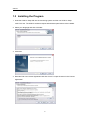
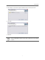
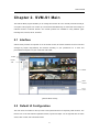

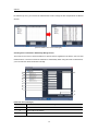
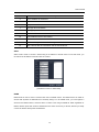
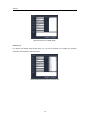
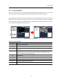
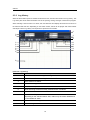
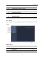
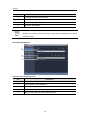
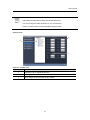
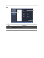
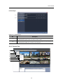
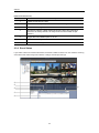
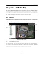
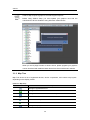
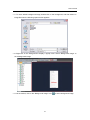
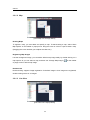
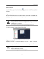
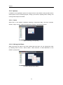
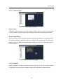

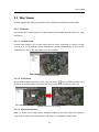

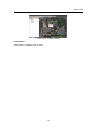

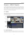
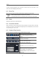
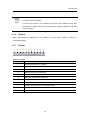
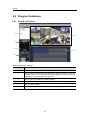
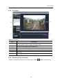

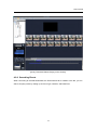
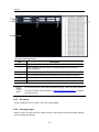
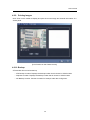
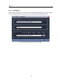

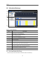
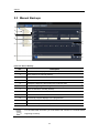
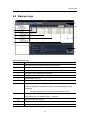
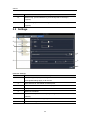

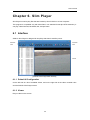

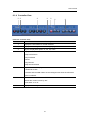

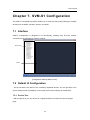

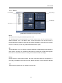
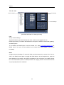
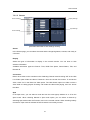
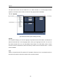
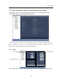
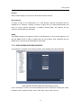
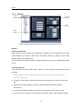
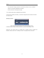
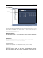
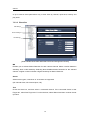
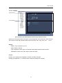
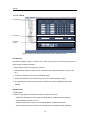
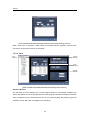
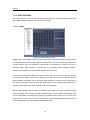

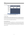
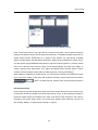
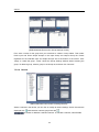
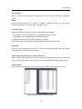
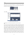
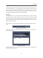
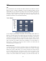
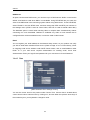
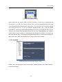
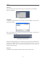
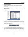
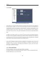
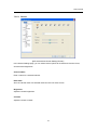

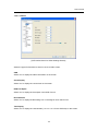
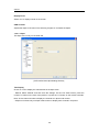
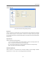
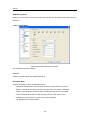
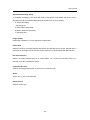
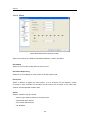
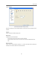

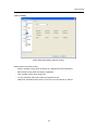

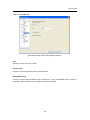
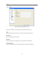
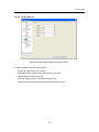
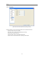
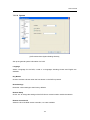
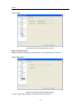
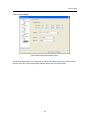
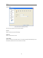


![User Manual [English]](http://vs1.manualzilla.com/store/data/005834880_1-d53398c0de391706aeb0ae49b4eb40a6-150x150.png)