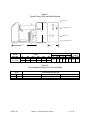
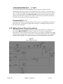
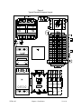
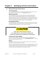
1
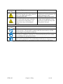
Mini & Micro Series Water Temperature Control Units Part Number: 882.12039.00 Bulletin Number: WTR1-605 Effective: August 1, 2012 Write Down Your Serial Numbers Here For Future Reference: _________________________ _________________________ _________________________ _________________________ _________________________ _________________________ We are committed to a continuing program of product improvement. Specifications, appearance, and dimensions described in this manual are subject to change without notice. DCN No. ____________ © Copyright 2012 All rights reserved. WTR1-935 ii Table of Contents CHAPTER 1: SAFETY................................................................ 5 1-1 How to Use This Manual .............................................................................................. 5 Safety Symbols Used in this Manual ..................................................................... 5 1-2 Warnings and precautions ............................................................................................ 7 CHAPTER 2: FUNCTIONAL DESCRIPTION ............................. 8 2-1 2-2 2-3 2-4 2-5 Models Covered in This Manual ................................................................................... 8 General Description ...................................................................................................... 8 Necessary Documents ................................................................................................. 9 Standard Features ........................................................................................................ 9 Available Options ........................................................................................................ 10 CHAPTER 3: SHIPPING INFORMATION ................................ 13 3-1 3-2 3-3 3-4 3-5 Unpacking and Inspection .......................................................................................... 13 In the Event of Shipping Damages ............................................................................. 13 If the Shipment is Not Complete ................................................................................. 13 If the Shipment is Not Correct .................................................................................... 14 Uncrating your Mini/Micro Series System ................................................................... 15 CHAPTER 4: INSTALLATION ................................................. 16 4-1 4-2 4-3 4-4 4-5 4-6 4-7 4-8 4-9 4-10 4-11 Work Rules ................................................................................................................. 16 Installation Requirements ........................................................................................... 16 Process Approach Temperature Considerations ........................................................ 16 External Piping Sizing Considerations ........................................................................ 17 Piping Considerations for Permanent Installations ..................................................... 17 Piping Considerations for High Mobility Installations .................................................. 18 Process Water Considerations ................................................................................... 18 Making Process Water Connections .......................................................................... 19 Making Cooling Water Connections ........................................................................... 19 Making System Purge Connections .......................................................................... 20 Making Electrical Connections .................................................................................. 21 CHAPTER 5: IDENTIFYING CONTROLS AND FEATURES... 26 5-1 5-2 5-3 5-4 5-5 5-6 5-7 5-8 5-9 Mechanical Controls and Features ............................................................................. 26 The Microprocessor Controller ................................................................................... 28 Identifying Controller Panel Components ................................................................... 29 Using CAL Controls Controller Keys .......................................................................... 29 Using CAL Controls Controller Keys .......................................................................... 30 Alarms ........................................................................................................................ 31 Controller Factory Setup ............................................................................................. 31 Operating the Unit with the Controller ........................................................................ 31 Communications ......................................................................................................... 31 CHAPTER 6: STARTUP AND OPERATION............................ 32 6-1 Introduction ................................................................................................................. 32 WTR1-935 iii 6-2 6-3 6-4 6-5 6-6 Startup Checklist ........................................................................................................ 32 Starting the Temperature Control Unit ........................................................................ 33 Sequence of Operation ............................................................................................... 34 Checking Motor Rotation Direction ............................................................................. 34 Shutting down the Temperature Control Unit ............................................................. 35 CHAPTER 7: MAINTENANCE ................................................. 36 7-1 7-2 7-3 7-4 7-5 7-6 Preventative Maintenance .......................................................................................... 36 Corrective Maintenance .............................................................................................. 37 Restoring the Controller Factory Setup ...................................................................... 38 Electrical Connections ................................................................................................ 38 Safety Devices ............................................................................................................ 39 Cleaning and Storage ................................................................................................. 39 CHAPTER 8: TROUBLESHOOTING ....................................... 40 CHAPTER 9: APPENDIX ......................................................... 43 Technical Assistance ........................................................................................................... 43 Parts Department ................................................................................................ 43 Sales and Contracting Department ..................................................................... 43 Facilities .............................................................................................................. 43 WTR1-935 iv Chapter 1: Safety 1-1 How to Use This Manual Use this manual as a guide and reference for installing, operating, and maintaining your granulator. The purpose is to assist you in applying efficient, proven techniques that enhance equipment productivity. This manual covers only light corrective maintenance. No other maintenance should be undertaken without first contacting a service engineer. The Functional Description section outlines models covered, standard features, and safety features. Additional sections within the manual provide instructions for installation, preoperational procedures, operation, preventive maintenance, and corrective maintenance. The Installation chapter includes required data for receiving, unpacking, inspecting, and setup of the equipment. We can also provide the assistance of a factory-trained technician to help train your operator(s) for a nominal charge. This section includes instructions, checks, and adjustments that should be followed before commencing with operation of the granulator. These instructions are intended to supplement standard shop procedures performed at shift, daily, and weekly intervals. The Operation chapter includes a description of electrical and mechanical controls, in addition to information for operating the granulator safely and efficiently. The Maintenance chapter is intended to serve as a source of detailed assembly and disassembly instructions for those areas of the equipment requiring service. Preventive maintenance sections are included to ensure that your granulator provides excellent, long service. The Troubleshooting chapter serves as a guide for identification of most common problems. Potential problems are listed, along with possible causes and related solutions. The Appendix contains technical specifications, drawings, schematics, parts lists, and available options. A spare parts list with part numbers specific to your machine is provided with your shipping paperwork package. Refer to this section for a listing of spare parts for purchase. Have your serial number and model number ready when ordering. Safety Symbols Used in this Manual The following safety alert symbols are used to alert you to potential personal injury hazards. Obey all safety messages that follow these symbols to avoid possible injury or death. DANGER indicates an imminently hazardous situation that, if not avoided, will result in death or serious injury. WARNING indicates a potentially hazardous situation or practice that, if not avoided, could result in death or serious injury. CAUTION indicates a potentially hazardous situation or practice that, if not avoided, may result in minor or moderate injury or in property damage. WTR1-605 Chapter 1: Safety 5 of 44 Hazard Alert Symbol Mandatory Symbol Description/Explanation Preventative Maintenance High Voltage Hazard. The electrical enclosure is supplied with 3-phase electrical power. Use caution when using or maintaining this product. Hot Surface Hazard. When the unit operates above 212F (100C) the surface of the unit may reach excessive temperatures. Use caution when using or maintaining this product. Every six months inspect all electrical connections for secure attachment. For further information see the Maintenance Chapter in this manual Every six months inspect all surfaces for signs of heat degradation. If any appear remove panel and verify cause of degradation and repair. Description/Explanation Read Operators Manual. This equipment must be operated and maintained by properly trained personnel. The information contained within this manual must be read and understood prior to operating this equipment. Lock Out. This equipment is operated with 3-phase electrical power. Therefore, when performing any maintenance operations we recommend following the local standards for performing a lock-out/tag-out procedure. Wear Safety Gloves. This equipment operates above 212F (100C) and its surfaces may reach excessive temperatures. We recommend that technicians use safety gloves while performing maintenance to protect hands from being exposed to these hot surfaces. WTR1-605 Chapter 1: Safety 6 of 44 1-2 Warnings and precautions Our units are designed to provide safe and reliable operation when installed and operated within design specifications, following national and local safety codes. To avoid possible personal injury or equipment damage when installing, operating, or maintaining this granulator, use good judgment and follow these safe practices: þ Follow all SAFETY CODES. þ Only PROPERLY TRAINED personnel familiar with the information within this manual should work on this equipment. þ TrueTemp Mini Series cabinets and piping are hot and are a BURN HAZARD. þ Wear SAFETY GLASSES and WORK GLOVES. þ Disconnect and/or lock out power before servicing or maintaining the hot oil temperature control unit. þ Use care when LOADING, UNLOADING, RIGGING, or MOVING this equipment. þ Operate this equipment within design specifications. þ OPEN, TAG, and LOCK ALL DISCONNECTS before working on equipment. You should remove the fuses and carry them with you. þ Make sure the hot oil temperature control unit and components are properly GROUNDED before you switch on power. þ When welding or brazing in or around this equipment, be sure VENTILATION is ADEQUATE. PROTECT adjacent materials from flame or sparks by shielding with sheet metal. An approved FIRE EXTINGUISHER should be close at hand and ready for use if needed. þ Do not jump or bypass any electrical safety control. þ Do not restore power until you remove all tools, test equipment, etc., and the hot oil temperature control unit and related equipment are fully reassembled. þ Do not restore power until all tools, test equipment, etc. have been removed and the panels replaced. þ Only PROPERLY TRAINED personnel familiar with the information in this manual should work on this equipment. We have long recognized the importance of safety and have designed and manufactured our equipment with operator safety as a prime consideration. We expect you, as a user, to abide by the foregoing recommendations in order to make operator safety a reality. WTR1-605 Chapter 1: Safety 7 of 44 Chapter 2: Functional Description 2-1 Models Covered in This Manual This manual lists installation, operation, and maintenance instructions for all mini/micro water temperature control units. Model numbers are listed on the serial tag. A model number followed by -Q indicates a specially constructed unit, and not all information in this manual may apply. Make sure that you know the model number, serial number, and operating voltage of your unit if you contact us. 2-2 General Description Mini/Micro Series water temperature control units are reliable, accurate, and easy-to-use process temperature control units. They are self-contained, portable, and shipped ready to use. Mini/Micro Series water temperature control unit is designed to circulate water through your process and to precisely, automatically, and reliably maintain it at a specified temperature. Standard unit operating range is from 0ºF (-17ºC) to 250°F (121°C). The unit is suited for use with city water, water from portable or central chillers or towers, or well water. These units are designed for rapid recirculation of a relatively small amount of water to provide close and uniform temperature relation between deliveries and return lines. This performance, of course, depends on the configuration of your process and any restrictions within the mold. The recirculation, combined with the large immersion heater and cooling capability, gives fast and accurate response to bring the water up to temperature or to changes in the settings when needed. The Mini/Micro Series water temperature control unit is a self-contained system consisting of a centrifugal pump, electric immersion heaters, cool/vent solenoid valve, and electrical control, including a PID microprocessor controller and thermocouple. It is designed for use in process temperature control applications using water or a water/glycol mix. Any other use or fluid is prohibited. Some standard safety devices include a mechanical over temperature safety thermostat, a pressure relief valve, motor overload protection, a low pressure cut-out switch, branch fusing, and non-fused lockable rotary disconnect. A properly installed, operated, and maintained water temperature control system provides years of reliable operation. Please read and follow the instructions in this manual to get the most satisfaction from your water temperature control system. WTR1-605 Chapter 2: Functional Description 8 of 44 2-3 Necessary Documents The following documents are necessary for the operation, installation, and maintenance of your Mini/Micro Series water temperature control units. Additional copies are available from ACS Group Familiarize the appropriate personnel with these documents: þ This manual. þ The controller operation manual. þ The electrical schematic and connection diagram placed inside the manual envelope. þ The operation and installation manuals for accessories and options selected by the customer. The Customer Parts List included in the information packet. 2-4 Standard Features • Compact, rugged cabinet with easy-access side panels • Non-ferrous construction • Incoloy™ immersion heaters with IEC contactors • NEMA 1 electrical enclosure • CAL 9000 microprocessor controller with fuzzy logic; includes status lights; CE and CUL • Independent high temperature safety thermostat • Motor Circuit Protector for pump • ¼” cooling solenoid valve • EPDM/Carbon-carbide pump seal • Adjustable low supply water pressure switch; factory-set at 16 psig (110 kPa/1.1 bars) • 150 psig (1,034 kPa/10.3 bars) pressure relief valve • Choice of 208, 230 or 460 operating voltages • ¾” water supply and drain connections; ¾” process connections WTR1-605 • Automatic vent sequence • Operating range of 32ºF to 250ºF (-17ºC to 121ºC) • One (1) -year parts and labor warranty at the factory; three (3) -year controller warranty Chapter 2: Functional Description 9 of 44 . 2-5 Available Options Mini/Micro Series systems are available with options to tailor the unit to your requirements. Some are factory installed; some can be retro-fitted in the field. Consult your ACS Group sales representative for more information. Available options include: WTR1-605 • RS-232 or RS-485 communications • Remote controller enclosure • Heaters available in 3 kW, 6 kW, and 9 kW • Quick Cool function • Auto system water purge (mold purge) • Y-strainer • Remote start/stop control • Casters; available in lieu of rubber feet • Audible and visual general fault alarm • Rotary, through-the-door disconnect switch • Electrical operation available in 208, 230, 460, and 575 volts, 60 Hz; 200, 380, and 415 volts, 50 Hz • UL/CUL-listed electrical subpanel • 10 ft. power cord • Manual bypass • Pressure regulator on water supply Chapter 2: Functional Description 10 of 44 Figure 1 Typical Control Unit and Specifications To Process Cooling Water Out 17.5” From Process Cooling Water Inlet 23” 9.5” Model 460 / 230 3 kW heater Pump hp 1/2 3/4 kW 0.37 0.56 gpm 15 20 lpm 57 76 H psig 25 30 kPa 138 159 in. Dimensions W D cm in. cm in. cm Shipping weight lbs. Kg 17½ 44.0 9½ 24.0 23 58.0 110 Figure 2 TrueTemp Mini Series Unit Full-Load Amps Model hp kW 0.5 hp 0.37 kW 0.75 hp 0.56 kW WTR1-605 Full-load amps at 460 volts 3 kW heater 4.8 amps 5.2 amps 6 kW heater 8.5 amps 8.9 amps Chapter 2: Functional Description 9 kW heater 12.3 amps 12.7 amps 11 of 44 50 WTR1-605 Chapter 2: Functional Description 12 of 44 Chapter 3: Shipping Information 3-1 Unpacking and Inspection You should inspect your Mini/Micro Series temperature control unit for possible shipping damage. If the container and packing materials are in reusable condition, save them for reshipment if necessary. Thoroughly check the equipment for any damage that might have occurred in transit, such as broken or loose wiring and components, loose hardware and mounting screws, etc. In case of breakage, damage, shortage, or incorrect shipment, refer to the following sections. 3-2 In the Event of Shipping Damages Important! According to the contract terms and conditions of the Carrier, the responsibility of the Shipper ends at the time and place of shipment. þ Notify the transportation company’s local agent if you discover damage. þ Hold the damaged goods and packing material for the examining agent’s inspection. Do not return any goods to ACS Group before the transportation company inspection and authorization. þ File a claim against the transportation company. Substantiate the claim by referring to the agent’s report. A certified copy of our invoice is available upon request. The original Bill of Lading is attached to our original invoice. þ Advise ACS Group regarding your request for assistance and to obtain an RMA (return materials authorization) number. 3-3 If the Shipment is Not Complete Check the packing list. The apparent shortage may be intentional. Back-ordered items are noted on the packing list. You should have: þ Mini/Micro Series water temperature control unit þ Bill of lading þ Packing list þ Operating and Installation packet þ Electrical schematic and panel layout drawings þ Component instruction manuals WTR1-605 Chapter 3: Shipping Information 13 of 44 Re-inspect the container and packing material to see if you missed any smaller items during unpacking. Determine that the item was not inadvertently taken from the area before you checked in the shipment. Notify ACS Group immediately of the shortage. 3-4 If the Shipment is Not Correct If the shipment is not what you ordered, contact the shipping department immediately. For immediate assistance, please contact the correct facility located in the technical assistance section of this manual. Have the order number and item number available. Hold the items until you receive shipping instructions. Returns Do not return any damaged or incorrect items until you receive shipping instructions from the shipping department. Credit Returns Prior to the return of any material, authorization must be given by the manufacturer. A RMA number will be assigned for the equipment to be returned. Reason for requesting the return must be given. ALL returned material purchased from the manufacturer returned is subject to 15% ($75.00 minimum) restocking charge. ALL returns are to be shipped prepaid. The invoice number and date or purchase order number and date must be supplied. No credit will be issued for material that is not within the manufacturer’s warranty period and/or in new and unused condition, suitable for resale. Warranty Returns Prior to the return of any material, authorization must be given by the manufacturer. A RMA number will be assigned for the equipment to be returned. Reason for requesting the return must be given. All returns are to be shipped prepaid. The invoice number and date or purchase order number and date must be supplied. After inspecting the material, a replacement or credit will be given at the manufacturer’s discretion. If the item is found to be defective in materials or workmanship, and it was manufactured by our company, purchased components are covered under their specific warranty terms. WTR1-605 Chapter 3: Shipping Information 14 of 44 3-5 Uncrating your Mini/Micro Series System þ Mini /Micro Series water temperature control units are shipped in a four-fold cardboard box, surrounded by expandable foam. þ Carefully lift the unit out of the carton. Caution, the unit weighs 110 lbs. Be careful when cutting straps. Straps may spring back and cause injury! þ Carefully remove the staples on the top of the box, and open the top two (2) flaps. þ Remove the foam packing from the top of the box. þ Carefully cut the bands on the cardboard box. This removes the box from the base. WTR1-605 Chapter 3: Shipping Information 15 of 44 Chapter 4: Installation 4-1 Work Rules The installation, operation, and maintenance of this equipment must be conducted in accordance with all applicable work and safety codes for the installation location. This may include, but is not limited to OSHA, NEC, CSA, and any other local, national, and international regulations. • Read and follow these instructions when installing, operating, and maintaining this equipment. If the instructions become damaged or unreadable, obtain additional copies from ACS Group. • Only qualified personnel familiar with this equipment should work on or with this hot oil temperature control unit. • Work with approved tools and devices. • Disconnect the electricity before maintenance or service. If the unit is installed with a power cord that can be un- plugged, unplug it. If the unit is permanently wired to a power main, make sure that a fused power disconnect is installed to allow the disconnect to be locked in the OFF position. Open and lock out the disconnect installed in the control enclosure. 4-2 Installation Requirements Mini/Micro Series systems are portable and can be installed almost anywhere. As with all equipment installations, follow all applicable codes and regulations. 4-3 þ The recommended ambient temperature range for Mini/Micro Series installations is from +14ºF (-10ºC) to a maximum operating ambient temperature of 131°F (55ºC). Recommended ambient storage temperature range is from -13ºF to 149ºF (-25ºC to 65ºC). If storing the unit below freezing temperatures, make sure the unit has an anti-freeze mixture circulated inside. þ Provide a minimum of twelve inches (12” or about 30 cm) clearance on all sides of the cabinet to allow circulation of cooling air. þ Locate the unit as close to the process as practical. Process Approach Temperature Considerations If the differential between COOLING WATER IN and TO PROCESS temperatures is less than 10°F (7ºC), consult our Sales Department for advice on how to control low approach applications. WTR1-605 Chapter 4: Installation 16 of 44 4-4 External Piping Sizing Considerations þ All external hose and piping should be adequately sized to assure minimum external pressure drop. þ Low external piping pressure drop is needed for best operation. Use a backup wrench to support water temperature control system piping when making process piping connections All external valves, fittings, and hoses must be rated at a minimum of 150 psig and 250ºF (1,034.25 kPa/10.34 bars and 121ºC). 4-5 Piping Considerations for Permanent Installations It is recommended that an optional (or customer-installed) strainer on the COOLING WATER IN inlet. The unit must have at least 16 psig (110.32 kPa/1.1 bars) water supply pressure to prevent pump cavitation that can be caused by the water “flashing” to steam. To avoid damage to the pump or other components, make sure that maximum supply pressure does not exceed 55 psig (275.8 kPa/2.8 bars). Keep restrictions to a minimum by using proper inlet pipe sizing. If the water supply piping is larger than ¾”, reduce the size at the unit. The table below contains the pipe sizes that are used in the unit. Pipe sizes for ½ hp and ¾ hp (0.37 kW and 0.56 kW) units Location Size in inches NPT Process delivery ¾” Process return ¾” Water supply ¾” Drain ¾” Common black pipe is recommended for permanent installations. Mini/Micro Series water circuit piping is non-ferrous (stainless steel and brass) and reacts electro-chemically with ferrous metallic materials such as iron. Some water contains dissolved minerals that greatly accelerate the reaction between dissimilar metals. Non-ferrous piping is recommended to minimize galvanic action. If piping must be copper, use dielectric unions at the unit. WTR1-605 Chapter 4: Installation 17 of 44 4-6 Piping Considerations for High Mobility Installations Mobile water temperature controls systems must use high quality hose rated for at least 150 psig and 250°F (1,034.25 kPa/10.34 bars and 121ºC). Quick disconnects may be used for mobility, although they cause a drop in pressure. If used, they must be sized carefully to minimize pressure drop. Don’t use quick disconnects with check valves unless absolutely necessary. Non-relieving quick connect fittings or check valves on the water supply must have a pressure relief piped to the drain. Failure to do so could result in a dangerous over-pressure condition! 4-7 Process Water Considerations Raw Water Water treatment is vital in any piping system. In some cases, raw water may be used in the system without problems; in other cases, it can result in large deposits of scale and corrosion. ACS Group offers a complete line of water treatment equipment. Contact your sales representative for water testing and treatment options. Distilled Water Non-ferrous (brass, copper, or high-temperature plastic) piping is recommended for distilled water processes. Deionized Water Stainless steel (316 SS minimum) or PVC plastic components must be used with deionized water. It is recommended that stainless steel because of the temperature constraints with plastic. WTR1-605 Chapter 4: Installation 18 of 44 4-8 Making Process Water Connections Direct Injection For both types of systems, the connections are basically the same. On the back of each unit, the connections are labeled appropriately. Connect the TO PROCESS hookup to the entrance of the process and the FROM PROCESS hookup to the exit of the process. Connect the COOLING WATER INLET SUPPLY to your plant water supply. Connect the COOLING WATER OUT line to an open drain, or to the return line of your central water system. Make sure you carefully select the connecting lines and connectors between the temperature control unit and the process to suit the needs and requirements of your application. If your unit has a maximum operating temperature of 250ºF (121ºC), the connecting lines and connectors should have a service rating of at least 250ºF (121ºC) and 150 psig (1,034.25 kPa/10.34 bars). TO PROCESS — ¾” NPT This is the outlet for the tempered water leading to the process being controlled. FROM PROCESS — ¾” NPT Water from the process re-enters the Mini/Micro Series system to be tempered and recirculated back into the process. 4-9 Making Cooling Water Connections Cooling Water InLET — ¾” NPT The cooling water supply inlet from a cooling tower, a chiller, or a city water supply. If a non-relieving device such as a regulator, ball valve, or check valve is installed on the WATER IN line, you MUST install an expansion tank of at least ½ gallon (about 2 liters) capacity. Failure to do so can result in system overpressure from thermal expansion. Install the tank configured as shown below: Check the expansion tank frequently to make sure it is not flooded. WTR1-605 Chapter TCU 4: Installation 19 of 44 COOLING WATER OUT — ¾” NPT The cooling water return outlet leading back to the cooling tower, chiller, or drain. Net supply pressure must be between 16 psig and 40 psig (172.38 kPa/1.72 bars and 517.13 kPa/ 5.17 bars). Net supply below 15 psig (103.43 kPa/1.03 bars) may allow water to flash to steam, cavitate the impeller, and damage the pump, which prevents the unit from cooling properly. Operation above 40 psig (517.13 kPa/5.17 bars) may cause premature opening of the relief valve from pump pressure and pressure surges. Pressure Relief — ¾” The pressure relief valve is located at the back of the unit. It is recommended to run a hose or pipe to the floor. This hosing or piping reduces the chance of scalding nearby personnel if the relief valve should trip. 4-10 Making System Purge Connections Mini/Micro Series systems equipped with the System Purge option have a compressed air inlet marked MOLD PURGE (See Below). Connect to a clean, dry 100 psig (689.50 kPa/6.90 bars) air line. Install your own shut-off valve to prevent process liquid from backing up into the plant air piping if the compressed air is turned off and the check valve fails. Don’t depend on the solenoid valve to hold water pressure in the temperature control unit. Figure 2 Typical Piping Schematic WTR1-605 Chapter 4: Installation 20 of 44 4-11 Making Electrical Connections TrueTemp Mini Series systems are designed for three-phase voltage operation. Refer to the unit nameplate for proper voltage and amperage requirements. Make sure you provide a correctly sized and protected supply of electrical power to the unit. Refer to National Electric Code (NEC) Article 430-24 through 430-26 for proper feeder conductor and supply disconnect sizing. Maintain a safe ground and disconnect the power supply before servicing the unit. A qualified electrician should make electrical connections, and disconnect and lock out electricity using OSHA 29CFR 1910.147 standards when you need a service call. Check serial tag voltage and amperage requirements and make sure your electrical service conforms before making any electrical connections. Total running amps for Mini/Micro Series systems are listed on the nameplate. Customer connections can be run to the supply terminals from either side of the unit. Make sure that all three phases are wired correctly. If not wired properly, the unit will run backwards. Again, check the unit nameplate for correct voltage and amperage. Improper electrical connections can damage the unit and cause serious operator injury or death! Bring properly sized power leads and ground from a fused disconnect (installed by your electrician) to the unit. Provide external overcurrent protection to the unit, using circuit breakers or fuses. If you use fuses, make sure that they are dual-element time-delay fuses, sized according to your electrical code. Make sure that all electrical connections are tight. WTR1-605 Chapter 4: Installation 21 of 44 1. Electrical connections must comply with all applicable electrical codes. 2. The temperature control unit must be grounded in accordance with NEC Article 250. 3. Voltage must be within plus or minus ten percent (±10%) of the nameplate rating. 4. Make sure your installer provides external protection. WTR1-605 Chapter 4: Installation 22 of 44 Figure 3 Typical Electrical Wiring Schematic, Drawing 1 WTR1-605 Chapter 4: Installation 23 of 44 Figure 3 Typical Electrical Wiring Schematic, Drawing 2 WTR1-605 Chapter 4: Installation 24 of 44 Figure 4 Typical Electrical Subpanel Layout WTR1-605 Chapter 4: Installation 25 of 44 Chapter 5: 5-1 Identifying Controls and Features Mechanical Controls and Features To Process Probe One (1) type K thermocouple probe is included with your Mini/Micro temperature control unit. It is located in the heater tank to sense TO PROCESS temperature. Safety Thermostat The safety thermostat mounted on the side of the heater tank protects against thermal runaway. The thermostat guards against the unlikely event of “runaway” heating. If overheating occurs, the safety thermostat shuts down heater outputs. The unit continues to pump water through the system to prevent heater damage. It is recommended that you install an audible or visual alarm to the terminals provided. Factory installed alarms are available; see the electrical schematics in Figure 3 in Chapter 4 for more information. Pressure Relief Valve If the combined pressure of the cooling supply water and pump discharge exceeds 150 psig (1,034.25 kPa/10.34 bars), the pressure relief valve opens and relieves the pressure. This is a non-adjustable ASME construction valve with a stainless steel spring. Route a pipe from the pressure relief valve to a suitable drain to reduce potential scalding hazard. The drain line must not have any restrictions or back pressure. Low Pressure Cutout Switch This switch, set at 16 psig with a 2 psig differential (110.3 kPa/ 1.10 bars with a 13.79 kPa/0.14 bars differential) shuts down the unit if the COOLING WATER IN water pressure drops below 16 psig (110.3 kPa/1.10 bars). Pumps Pumps range in power from ½ hp to ¾ hp (0.37 kW to 0.56 kW) and are equipped with 3phase ODP motors and seal flush lines as standard. The pump is a stamped stainless steel, bronze-fitted close-coupled centrifugal type. It features a split case design to facilitate replacement of the seal. It has a high output capacity with excellent discharge pressure helping it facilitate turbulence to maximize heat transfer, and is well suited for the conditions under which it was designed to operate. WTR1-605 Chapter 5: Identifying Controls and Features 26 of 44 Heaters The specially designed 3, 6, or 9 kW three-phase low watt density electrical immersion heaters heat the water, and the controller regulates the temperature. The standard heater has an incolloy sheath for best heat transfer and low fouling properties. Solenoid Valves TrueTemp Mini Series systems use rugged, industrial design solenoids with replaceable coils and/or internal components. The unit is equipped with a ¼” direct acting solenoid valve. Pump Starter Mini/Micro Series high quality IEC-rated Motor Circuit Protectors (MCPs) are industrial grade motor controls with overload protection and manual reset. Transformer High quality industrial design transformers are specified to suit incoming voltage on the application and provide 115 VAC control voltage. The 115 VAC circuit is protected by primary fusing and secondary grounding. Heater Contactor Your temperature control unit uses high-quality IEC-rated industrial grade electromechanical contactors for heater controls. Cooling The controller automatically regulates cooling by opening and closing the solenoid valve. For direct injection, the unit cools by removing the required amount of warm water from the system. This process permits an equal amount of cool plant water to enter the system well ahead of the pump, allowing it to blend with the system water. The water supply temperature governs the minimum operating temperature of the unit. Electricals The pump motor and the immersion heater operate on three-phase 50/60 cycle nominal voltages with the control circuit operating at 115V single phase. The control circuit voltage is provided by a single phase machine tool transformer with a grounded secondary. The 115V control circuit and controller outputs are fuse protected. The pump motor is controlled by a full voltage magnetic non-reversing motor starter, with fused branch circuit overcurrent and thermal overload protection. Automatic Vent This feature automatically triggers the purging of air from the system before you start the unit. The vent actuates the solenoid valve, and forces trapped air and water out through the drain, properly filling and priming the unit prior to startup. Complete venting is necessary to prevent damage to the pump and heater. The vent process is controlled through a timer. If you have a large process, you may need to complete the venting process by pressing the VENT button on the front-mounted switch panel. WTR1-605 Chapter 5: Identifying Controls and Features 27 of 44 Pressure Switch A pressure switch built into each unit keeps the system from starting until the water supply is turned On and subjected to the minimum water supply pressure. This feature protects the pump seal and the heater from damage through attempted operation without water. The pressure switch is set at approximately 16 psig (110.32 kPa/1.10 bars) for 250°F (121ºC) units prior to leaving the factory. 5-2 The Microprocessor Controller The CAL 9300 controller is an easy-to-operate microprocessor-based PID control device. When the process reaches the set point, the PID control cycles the cooling valve and/or immersion heater to maintain the proper leaving water temperature. The controller is fully factory tested. Set the process temperature set point you want and the controller does the rest. Built-in range of operation on the controller is 32°F to 250°F (0ºC to 121ºC). Figure 5 Typical Graphic and Button Control Panels WTR1-605 Chapter 5: Identifying Controls and Features 28 of 44 5-3 Identifying Controller Panel Components Screen Displays Numeric LED During normal operation, the LED on the controller displays the process temperature of the fluid in the heater tank. It also displays parameter and pre-set function values during setup. Status Indicators OUT1 Indicator The OUT1 indicator is on when the fluid temperature is below the set point and is being heated. OUT2 Indicator The OUT2 indicator is on when fluid temperature is above the set point and is being cooled. Display Indicators LED Indicator Under normal operation the LED indicator displays the temperature of the outgoing fluid. To view the setpoint press the star (*) key. 5-4 Using CAL Controls Controller Keys Star (*) Key Press and hold the Star (*) key to view the setpoint. Press the Star (*) Key and the together to increase the setpoint. Press the Star (*) Key and the the setpoint. together to decrease UP Arrow Key Press the UP Arrow key to scroll through the functions, or increment or advance the values or settings on the LED screens. DOWN Arrow Key Press the DOWN Arrow key to scroll through the functions, decrement or reduce the values or settings on the LED screens. WTR1-605 Chapter 5: Identifying Controls and Features 29 of 44 Do not change any of the control settings without consulting the ACS Group Service Department. The warranty does not cover TCU failures from tampering with controller settings! 5-5 Using CAL Controls Controller Keys ON/OFF Switch Push the ON/OFF rocker switch to the ON ( | )energize the unit and begin the temperature control cycle. The switch will be illuminated whenever the unit is on. VENT Switch Push the VENT switch for additional manual venting. ALARM SILENCE Switch Optional Push the ALARM SILENCE button to silence the alarm. You should investigate the alarm condition and restore the unit to normal operation before continuing with the temperature control cycle. AIR PURGE Optional Press the AIR PURGE switch to initiate the purge. It is a momentary switch and must be pressed to keep the purge valve open. Releasing the switch closes the cooling/vent and compressed air solenoid valves. QUICK COOL Switch Optional Press the QUICK COOL switch to open the cooling valve and quickly cool the process. WTR1-605 Chapter 5: Identifying Controls and Features 30 of 44 5-6 Alarms Audible/Visual General Fault Alarm Optional The audible/visual general fault alarm sounds if any fault triggers, such as low water pressure, over-temperature, or pump overload. A signal from any of the safety devices activates a horn and flashing strobe. n 5-7 Push the ALARM SILENCE switch to silence the alarm. The optional mechanical high temperature safety alarm is interlocked with the heater. When triggered, the heater cuts out and the pump continues to run. Controller Factory Setup The controller is set up and tested at the factory for optimum operation, and doesn’t need to be adjusted. If the controller does not work properly, or you suspect someone has accidentally changed some settings, you can do two things. First, perform the Auto-Tune Procedure described in the following section. If that doesn’t work, restore the controller to the original factory settings as described in the appendix. 5-8 Operating the Unit with the Controller To change the process temperature set point: • Press * and together to decrease setpoint. • Press * and together to increase setpoint. The set point automatically updates. 5-9 Communications A connection port on the electrical cabinet permits easy hook-up to the host computer for RS232C and RS-485 communications. The connection port is a direct pin-to-pin extension from the back of the controller. WTR1-605 Chapter 5: Identifying Controls and Features 31 of 44 Chapter 6: Startup and Operation 6-1 Introduction The checklist below outlines start-up procedures for TrueTemp Mini Series water temperature control units. This list assumes that installation information located in this manual has been read and followed. 6-2 Startup Checklist þ Check the shipping papers against the serial tag to make sure that system size, type, and voltage is correct for the process under control. þ Check the transformer primary voltage connections to be sure they are configured for the electrical power you are using. The voltage at the main power connection must be within plus or minus ten percent (±10%) of the voltage listed on the serial tag. Electrical connections must conform to all applicable codes. Make sure that a qualified electrician checks all electrical connections. þ The safety thermostat is preset at the factory to trip at 265ºF (129ºC). þ The relief valve should be piped to an open, unrestricted drain. þ TO PROCESS, FROM PROCESS, WATER IN, WATER OUT, and MOLD PURGE connections should be complete. Only use components rated at a minimum of 150 psig and 250ºF (1,034.25 kPa/10.34 bars and 121ºC). WTR1-605 þ All outer panels must be in place. þ All external process valving should be set for proper operation of the unit. þ Cooling and/or makeup water between 16 psig and 55 psig (110.32 kPa/1.1 bars and 517.13 kPa/5.17 bars) must be available for the unit to operate properly. þ Connect the main power to the unit disconnect switch, and press the ON/OFF switch to the ON position to check for proper pump rotation direction as described in Section 5-6 on Page 42. Pump rotation should be clockwise, viewed from the motor end. þ Check your work and proceed to the Startup Procedure section on the following page. Chapter 6: Startup and Operation 32 of 44 6-3 Starting the Temperature Control Unit þ Turn ON the water supply, and push the ON/OFF switch to the ON ( | ) position. þ The unit automatically executes a one-minute venting sequence to expel air trapped in the process piping. AEC, Inc. recommends a longer venting sequence on larger process systems. Press and hold the VENT button to force the cooling/vent valve open and eliminate air trapped in the process piping in larger process systems. The controller is OFF during the vent sequence. þ Set the microprocessor controller to the process temperature you want by pressing and holding the * and keys or * and keys until the SET POINT screen displays the set point temperature you want. þ Watch the drain for any bubbles or erratic flow, which indicates if the system has not been properly vented. If the stream is steady, the unit was properly vented and all air is out of the system. þ Operate the unit, checking for anything unusual that could indicate improper operation. You can stop the temperature control unit at any time by pressing the ON/OFF switch to the OFF ( O ) position. 1) Your TrueTemp Mini Series system operates with hot water under pressure. To reduce the risk of scalding: • • • • Always wear work gloves and safety glasses when operating the unit. Never operate the unit with panels or shields removed. Pipe the relief valve to an open drain. Never install a fitting or hose that is rated less than 150 psig and 250ºF (1,034.25 kPa/10.34 bars and 121ºC). 2) To reduce the risk of electrical shock: • • • • WTR1-605 All electrical installation and repairs should be done by a qualified electrician. Ground the unit in accordance with electrical codes. Never attempt any repairs without first opening and locking out the main disconnect. Never deactivate or neutralize any safety device. Chapter 6: Startup and Operation 33 of 44 6-4 Sequence of Operation The simplicity of design and the highly engineered controller make this unit almost selfoperating. The ON/OFF and VENT switches and the temperature controller buttons are all that is required to operate this unit. After you complete all connections, turn the water supply ON, then turn control power ON. The unit automatically vents for a preset time of one (1) minute. If you need additional vent time, press the VENT button on the control panel. As the water comes in the water supply line, the water must enter the pump, up through the tank and out through the TO PROCESS line, through the process, back through the FROM PROCESS line, and through the solenoid line and out the COOLING WATER OUT line. þ TCU systems provide temperature control on processes by directly heating the process water and injecting cooling water into the process water. þ When the unit is energized, the pump starts and a one minute vent sequence opens the cooling/vent valve to remove any air trapped in the process piping. þ If the cooling water supply pressure is insufficient, the low cooling water pressure cutout switch (set at 16 psig, 2 psig differential [110.32 kPa/1.10 bars, 68.95 kPa/0.69 bars differential]) opens. You need at least 16 psig (110.32 kPa/1.10 bars) for the best cooling capacity and to prevent water boiling in the process circuit at high temperatures, particularly at the pump suction. þ After venting, the microprocessor controller monitors the TO PROCESS RTD Thermocouple probe, cycling open the cooling/vent valve to discharge warm water or energizing the immersion heater to maintain the process set temperature. 6-5 Checking Motor Rotation Direction Check for correct pump rotation direction by looking at the end of the motor. Press the ON/OFF switch from the OFF ( O ) position to the ON ( | ) button, and note the direction that the motor turns. Rotation should be clockwise when viewed from the motor end. Make sure that a qualified electrician performs the following steps. To change rotation direction: WTR1-605 1. Disconnect and lock out power at the customer supplied fused disconnect. 2. Reverse any two incoming leads at the power terminal blocks. 3. Do not switch leads at the motor or motor starters. Chapter 6: Startup and Operation 34 of 44 6-6 Shutting down the Temperature Control Unit Cool the unit down by selecting a set point of zero (0 ). Let the unit stabilize at one temperature close to the incoming water temperature, then press the ON/OFF switch to the OFF ( O ) position. Now press the VENT button to relieve any remaining pressure in the system. Finally, shut off the main power supply to the unit. Make sure you provide a correctly sized and protected supply of electrical power to the unit. Refer to National Electric Code (NEC) Article 430-24 through 430-26 M for proper feeder conductor and supply disconnect sizing. a Maintain a safe ground and disconnect the power supply before servicing the unit. A qualified electrician should make electrical connections, and disconnect and lock out electricity using OSHA 29CFR 1910.147 standards when you need a service call. WTR1-605 Chapter 6: Startup and Operation 35 of 44 Chapter 7: Maintenance Never attempt to service a unit until a qualified electrician has opened and locked out the main disconnect using OSHA 1910.147 standards. The water supply should be turned off and internal pressure should be relieved before you remove panels. All electrical connections must be done by a qualified electrician. Disconnect all power to the unit, let the unit cool down, and turn off the water prior to any servicing. Failure to do so can result in SERIOUS INJURY OR DEATH! 7-1 Preventative Maintenance Draining Drain the unit thoroughly if you are taking it out of service for a long period of time, or you expose it to freezing. Drain plugs are provided at the base of the heater tank and at the base of the pump. WTR1-605 Chapter 7: Maintenance 36 of 36 Periodic Checks Every Six Months Inspect all electrical connections for secure attachment and for safe and secure ground connections. Inspect heater contactors for loose wire connections or large amounts of carbon dust around contacts, as it may indicate the end of the life of the contactor. Inspect the power cable, especially at the entrance point to the unit. A qualified electrician should make this inspection. Check for leaks, especially under the pump, as it may indicate a worn pump seal. 7-2 Corrective Maintenance Pumps and Seals Before leaving our factory, we test each unit extensively, then we calibrate each unit. Afterwards, the unit is drained and blown out with air to remove water from piping systems. If the unit is allowed to stand idle for a long time before being installed in your factory, the housing gasket at the pump can dry out and can possibly leak when the unit is started. In most cases these gaskets will soon swell and form a tight seal. In other cases, it may be necessary for you to tighten the pump bolts to stop a leaking condition. Pump seal surfaces can separate slightly because of rough handling or from vibration during transit. This could cause a leak at the pump seal when the pump is started, but in most cases the surfaces will mate again after the pump is allowed to run for a short period of time. If they do not reseal, you may need to open the pump and free the seal by hand. It is seldom necessary to install a replacement seal in a new unit unless the seal has been damaged because the unit was started without water. Our pump seals have a long period of service life. Some conditions, of course, can shorten seal life, including the presence of grit, operation of the unit without water, sustained high water temperature, or presence of certain chemicals in the water. Our pump seal assembly has been developed to resist abrasive particles that are present in many water systems. This is done by a special flushing system that uses water exiting the pump to constantly wash the seal area. It is also fitted with high temperature flexible components for maximum heat resistance. These same components remain flexible even at low temperatures. Thus, the standard seal is a fine combination of heat resistant and wear resistant components. Unfortunately, even under normal use, the seal will eventually wear and require replacement. A small puddle underneath the unit is a sign of rotary seal wear, and if investigation confirms the pump as the source, the seal should be replaced as soon as practical. The water slinger is intended to provide temporary protection against this, but a continued and substantial leak will ruin the motor bearing and cause further damage. Under some conditions, the pump may not start. After turning off the power supply, check the motor shaft to be certain it is free to turn. By removing the drip cover on top of the motor, you’ll have access to the end of the shaft. It has been slotted to make it easy to turn with a screwdriver. If the shaft is free to turn, next check that the motor overloads are set, check for blown fuses, and finally check the power supply on each leg to the motor. A qualified electrician should check the motor and its circuit. WTR1-605 Chapter 7: Maintenance 37 of 37 If the pump motor wiring is disconnected for removal from the unit, make sure that you check the actual rotation direction when the motor is rewired to the unit. A phase sensor does not always indicate proper rotation if motor wire leads are reversed at installation. Consult the elementary wiring diagram for more information. Heaters Heaters may need to be cleaned chemically or mechanically to remove deposits and dirt that reduce heat transfer and cause hot spots. Hot spots cause premature heater failure. Install a new gasket when reassembling. Make sure a qualified electrician disconnects and reconnects heater wires. Solenoid Valves þ Clean annually, more often if using high mineral content water or on high service level units. þ Sluggish operation, excessive leakage, and/or noise indicate cleaning is necessary. Inspect the components for excessive wear while the valve is disassembled. Rebuild kits are available from the ACS Group Parts Department. 7-3 Restoring the Controller Factory Setup If the preset parameters on the controller have been tampered with and it no longer properly controls temperature, you can restore the controller to factory setup parameters. 7-4 Electrical Connections Make sure that a qualified electrician inspects all electrical components and connections every six (6) months for secure attachment and ground connections. Inspect all wiring for fraying or damage, especially power lines where they enter the unit. All wiring connections must be clean & tight. WTR1-605 Chapter 7: Maintenance 38 of 38 7-5 Safety Devices Make sure that only qualified electricians test safety devices! Safety devices should be tested for function every six (6) months. Perform the following procedures for testing: Pressure Switch With the unit running, program a set point of 30ºF (-1ºC). Allow the process temperature to drop under 100ºF (38ºC). When the process temperature reaches that point, turn off the water supply. The pump should stop and the Low Water Pressure indicator should illuminate. Turn the water supply on to reset the pressure switch. Safety Thermostat Disconnect main power. Open the electrical enclosure and disconnect the neutral lead on the safety thermostat from the terminal strip. Protect the stripped lead to prevent short circuits. Close the enclosure, reconnect main power, and push the START button. The heater should not turn on and the Over Temperature indicator should illuminate. Disconnect main power before reconnecting the thermostat lead. 7-6 Cleaning and Storage WTR1-605 • Inspect the unit daily for leaks. Wipe down the unit periodically to remove dirt and dust buildup, especially the motor casing. • Drain and flush the unit every six (6) months to remove sediment buildup. • Completely drain the unit and carefully blow out the piping with pressurized air before placing the unit in storage. Chapter 7: Maintenance 39 of 39 Chapter 8: Troubleshooting Condition Possible cause No power. Unit does not turn on. Wrong voltage supplied to unit. Defective on/off switch. Control circuit fuse blown. Defective control transformer. Broken or loose wire in pump motor control circuit. Pump motor contactor holding coil is open. Unit does not run. Pressure switch circuit is open. Water supply to unit is turned off. Open water supply. Foreign matter in the system. System has minimal back pressure, and is operating at the far end of the pump curve. Foreign matter obstructing system. Reset and test each leg for balanced amp draws. Verify proper rotation. If not clockwise, reverse any two incoming power leads. Clean the system. As long as there is satisfactory process temperature control there is no problem. Clean the system. Restricted water flow. Check for closed valves etc. Be sure all lines are properly sized. System has high back pressure, and is operating at the end of the pump curve; a low flow condition. As long as there is satisfactory process temperature control there is no problem. Insufficient cooling or makeup water pressure. Switch is broken. WTR1-605 Repair or replace. Check for at least 16 psig (110.32 kPa/1.1 bars) water pressure on WATER IN. Pump running in reverse. High pump pressure. Locate and repair. Low water pressure light on. Pump overload light on. Low pump pressure. Solution Check main disconnect, fuses, wiring, and power lead to unit. Voltage must be within plus or minus 10% of nameplate rating. Replace. Replace. Check transformer. Chapter 8: Troubleshooting Check for 16 psig (172.38 kPa/1.72 bars) water pressure on WATER IN. Replace switch if needed. 40 of 40 Condition Possible cause Undersized connectors/ water lines. Long connecting lines between unit and mold. Serpentine flow through mold. Temperature fluctuations/ rapid cycling from hot to cold. Blocked water line in mold. Quick disconnect fitting with check valve. Lime buildup in unit piping. Faulty Controller. Unit overheats or does not cool. COOLING WATER OUT Drain is plugged or excessive back pressure is in drain line. Clear drain line or eliminate back pressure condition. Faulty solenoid valve. Test solenoid valve by pressing VENT button and listen for valve operation. Replace if faulty. Controller Cool output relay open. Replace output relay. Solenoid valve is not operating, but OUT2 LED is on. Solenoid coil circuit is open. Relief valve leaks. Solution Increase size of connectors/ water lines. Move the unit closer to the mold and shorten connecting lines. Connect lines for parallel flow instead of series flow. Check mold for metal chips or lime buildup. Clean mold. Remove and replace fitting or valve. Clean or replace. Check unit by connecting ¾” line directly from delivery to return line. Run unit to determine if TCU Controller controls set point temperature. Insufficient pressure differential between cooling WATER IN and OUT lines. Heater contactor has welded shut. Foreign material under valve seat. High system pressure. Set process temperature to minimum and check for magnetism on solenoid coil top. Also check for voltage at the coil. Check coil resistance. If MΩ range, replace solenoid coil. Find a means to get less back pressure in the WATER OUT line. Replace contactor. Manually open valve to clear seat of material. Reduce WATER IN water pressure. Unit under-sized for application. Unit runs continuously cooling or heating, and cannot attain set point. Check heater output. Call sales representative. Check cooling circuit. WTR1-605 Chapter 8: Troubleshooting 41 of 41 Condition Possible cause Defective heater contactor. Defective immersion heater. Controller heat output open. Heater contactor is not energizing, but HEAT LED is on. Immersion heater elements dirty. Unit does not heat/cannot achieve set point. Immersion heater element is burned out. OUT1 indicator is on, but no voltage on heater contact. Cooling valve is leaking. Solenoid valve is not operating, but COOL LED is on. Magnetism on coil. Faulty/dirty solenoid valve. WTR1-605 Chapter 8: Troubleshooting Solution Visually inspect coil and contacts; repair/replace defective contactors. Check resistance on all three (3) legs of the heater with an ohm meter. If not all equal, contact factory for replacement heater. Check the heater output with an ohm meter to ground. It should read in the mega-ohm range. Infinite or zero readings indicate a defective output. Set process temperature to maximum and check for control voltage at heater contactor. Remove heater and clean elements. Check heater tank for scorched/discolored paint. Check resistance on all three (3) legs of the heater with an ohm meter. Replace heater as required. Check for balanced amp draws, and supply voltage. If not present replace immersion heater. Replace relay board on controller. Dismantle valve and clean out. Set process temperature to minimum and check for magnetism on top of solenoid coil. Clean coil. Press VENT button several times to flush the valve. 42 of 42 Chapter 9: Appendix Technical Assistance Parts Department The ACS Customer Service Group will provide your company with genuine OEM quality parts manufactured to engineering design specifications, which will maximize your equipment’s performance and efficiency. To assist in expediting your phone or fax order, please have the model and serial number of your unit when you contact us. A customer replacement parts list is included in this manual for your convenience. ACS welcomes inquiries on all your parts needs and is dedicated to providing excellent customer service. For immediate assistance, please contact: • North, Central and South America, 8am – 5pm CST +1 (800) 483-3919 for drying, conveying, heating and cooling and automation. For size reduction: +1 (800) 229-2919. North America, emergencies after 5pm CST (847) 439-5855 North America email: [email protected] • Mexico, Central & South America Email: [email protected] • Europe, Middle East & Africa +48 22 390 9720 Email: [email protected] • India +91 21 35329112 Email: [email protected] • Asia/Australia +86 512 8717 1919 Email: [email protected] Sales and Contracting Department Our products are sold by a worldwide network of independent sales representatives. Contact our Sales Department for the name of the sales representative nearest you. Let us install your system. The Contract Department offers any or all of these services: project planning; system packages including drawings; equipment, labor, and construction materials; and union or non-union installations. For assistance with your sales or system contracting needs please Call: North, Central and South America +1 (262) 641-8600 or +1 (847) 273-7700 Monday–Friday, 8am–5pm CST • Europe/Middle East/Africa +48 22 390 9720 • India +91 21 35329112 • Asia/Australia +86 512 8717 1919 Facilities ACS offers facilities around the world to service you no matter where you are located. For more information, please visit us at www.acscorporate.com. United States: Asia/Australia: India/Middle East ACS Schaumburg-Corporate Offices 1100 E. Woodfield Road Suite 588 Schaumburg, IL 60173 Phone: + 1 847 273 7700 Fax: + 1 847 273 7804 ACS Suzhou 109 Xingpu Road SIP Suzhou, China 215126 Phone: + 86 8717 1919 Fax: +86 512 8717 1916 ACS India Gat No. 191/1, Sandbhor Complex Mhalunge, Chakan, Tal Khed, Dist. Pune 410501, India Phone: +91 21 35329112 Fax: + 91 20 40147576 ACS New Berlin-Manufacturing Facility th 2900 S. 160 Street New Berlin, WI 53151 Phone : +1 262 641 8600 WTR1-605 Fax: + 1 262 641 8653 Europe: ACS Warsaw Ul. Działkowa 115 02-234 Warszawa Chapter 9: Appendix Phone: + 48 22 390 9720 Fax: +48 22 390 9724 43 of 43 WTR1-605 Chapter 9: Appendix 44 of 44