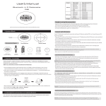
1
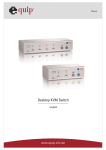
8-Port /16-Port
COMBO FREE
KVM SWITCH
User Manual
Version 1.0
Index
1. INTRODUCTION
3
1.1 Featurhs
3
1.2PACKAOUCONTHNTS
3
2. SPECIFICATIONS
2.1 GENERAL SPECIFICATION
4
4
3. SYSTEM REQUIREMENTS
5
4. INSTALLATION
5
4.1 FRONT VIEW
5
4.2 REAR VIEW
6
4.3 SINGLE STAGE INSTALLATION
6
4.4 CASCADE CHAINING
9
4.5 RACK MOUNTING
5. HOTKEY OPERATION
12
13
5.1 CALL OSD MENU
13
5.2 CHANNEL SELECT
13
5.3 AUTO-SCAN FUNCTION
14
5.4 BUZZER SOUND DISABLE / ENABLE
14
5.5 SETUP MODE
15
5.6 CASCADE CHAIN LAYER CHANGE
15
5.7 HOT-KEY SELECT
15
5.8 CONSOLE LOCK
15
5.9 CONSOLE UNLOCK
16
6. SUN MICRO SYSTEMS FUNCTION KEY EMULATION
7. OSD OPERATION
16
A7
7.1 OSD MAIN MENU
17
7.2 FUNCTION CONTROL MENU
17
8. TROUBLESHOOTING
22
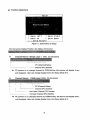
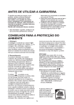
1. Introduction
Thank you for your purchase of Combo Free KVM Switch! You now have a high
quality, durable system that will enable you to control 8 or 16 Host computers
and/or servers by using PS/2 and/or USB Connectors from one console (PS/2
& USB Mouse, PS/2 & USB Keyboard, and Monitor).
1.1 Features
1. Console your Keyboard/Mouse via either way of PS/2 and/or USB arbitrarily.
2.
Complex connections with PCs via either way of PS/2 and/or USB arbitrarily.
3.
Controls 8 or16 computers from a single console (Keyboard/Mouse) over PS/2
and/or USB connections.
4. Supports Windows, Linux, Mac OS9/OSX, Sun Microsystems.
5. On-Screen-Display (OSD) & Cascade Chain functions.
- OSD is intuitive menus driven for quick and efficient navigation.
- 3 level cascades: up to 3 levels; control up to 64/256/4096 PCs, from a single
console; cascaded units don't need special configuration.
6. Emulates PS/2 or USB keyboard on each PC to allow your computers to boot
normally without a keyboard error.
7. Supports hot-pluggable. All devices connected to the KVM can be added or
removed at any time, without shutting the unit down.
8. Supports 3 types of switching:
(1) Hardware Push Button, (2) Hot-Keys on PS/2 and/or USB of keyboard,
(3) Menu driven OSD ( On Screen Display).
9. Supports Auto-Scan function to switch video automatically among computers in
preset intervals sequentially by OSD menu driven.
10. Supports LED display for PC and/or server status monitoring.
11. Supports VGA resolutions up to 2048 x 1536 @ 85HZ.
12. Supports Beeper during Switching enabled.
13. Powered with external power adaptor connection.
14. Fully compliant with the USB 1.1/ 2.0 specification.
15. Rack Mountable in 19" - inch (1U ).
1.2 Package Contents
The product you purchased should contain the following equipment and
accessories:
1
8-Port or 16-Port Combo Free KVM Switch .
1
User Manual.
1
Power adaptor
1
Rack Mount Kit
2
Combo custom 4-in-1 cable
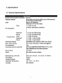
2. Specifications
2.1 General Specifications
Specification
3. System Requirements
Console
A VGA, SVGA, Multisync monitor capable of the highest resolution.
PS/2 and/or USB Keyboard/Mouse
Computer or Server
The following equipment must be equipped with each computer or server.
- A VGA, SVGA or Multisync card.
- Type A USB port or PS/2 6 pin mini-DIN for Keyboard and Mouse.
Cables
The Combo Free KVM Switch must be used specific custom 4-in-1 cables.
To purchase the specific cable sets, please contact your dealer.
4.
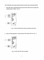
Installation
4.1 Front View
8-Port
16-Port
LED Indicators:
Selected : RED LED indicates that the KVM Switch is selected to the corresponding PC.
On-Line : GREEN LED indicates that the KVM Switch is ready to the corresponding PC.
Reset Switch :
Press this switch when a system reset. This switch must be pushed with a thin object,
for example, such as the end of a paper clip, or a ball point pen.
4.2 Rear View
8-Port
(=5
16-Port
n ettfsa1© eilEgJfc Gf.ffigJ©
4.3 Single stage installation
Precaution:
1.
Make sure all of devices are turning off as connecting up with KVM Switch.
You must unplug the power cords of any computers which might have the
Keyboard Power On function in advance. Otherwise, the switch will receive
power from the computer.
2.
With under running OS Windows 98 , we sugget that the PC must be plugged
to PS/2 ports, because of Windows 98 is not support installation at first time as
through USB HID installation driver.
3.
There are some of older PCs supported USB ports only, please open
BIOS USB setting in advance.
4.
The console plugging is not support USB keyboard of having USB HUB.
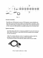
{ Fig. 1 )
Console connecting:
Plug either your USB keyboard, mouse or PS/2 keyboard, mouse arbitrarily and
VGA video into the Console ports located on the KVM Switch's rear panel. ( Fig.1)
( Note: No matter what you plugged even thought USB mouse with PS/2 keyboard
or PS/2 mouse with USB keyboard are available working to the KVM Switch unit.)
System connecting:
Use KVM custom cable sets to connect any available PC ports to the video and
either USB or PS/2 ports, or even USB & PS/2 all connected of the computers
you are connecting up.
( Note: The custome cable set, as Fig. 2, is supplied one cable set with this
package; any additional sets is required purchase separately.)
To purchase the custom KVM cable sets, please contact with your dealer.
( Fig 2 ) custom combo 4-in-1 cable
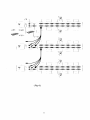
This KVM Switch with custom specific cable set provide three connecting methods.
1.
Plug USB, PS/2 ( keyboard/mouse) ports and VGA video into PCs at same time,
recommended in priority. ( Fig. 3 )
M ^2
a
( Fig. 3 ) PS/2 & USB and VGA video connected at same time.
2.
Plug only PS/2 (keyboard / mouse) ports and VGA video into PCs ( Fig. 4 ).
mm Ti
( Fig. 4 ) PS/2 and VGA video connected.
3.
Plug only USB and VGA video into PCs.
( Fig. 5 ).
WM
( Fig. 5 ) USB and VGA video connected.
4.4 Cascade Chaining
3 level cascades: up to 3 levels; control up to 64/256/4096 PCs, from a single
console; cascaded units don't need special configuration.
To set up cascade chained installation, please do the following:
1. Before you begin install, please make sure all of devices connected must be
turned off power before connecting.
2.
Use the custom cable set ( Fig. 2 ), cascade chain connecting the second and
third level of one or more Slave KVM Switches to any PC port of Master KVM
Switch. Cascade configuration expands system ability and allows you to select
computers connected to the Master or Slave. After connected, KVM Switches
automatically configure Master and Slave by themselves.
Note: The second and third level of Slave KVM Switch cascade chained via
custome cable set ( see ref. Fig. 2 ) is just only connected their
console ports of PS/2 Keyboard, PS/2 mouse and VGA video, no
more necessary to connecting USB port.
3. All of PC ports of Master KVM Switch and Slave KVM Switches could be
support connecting PCs or Servers via through methods ( Fig 3 ),
or ( Fig.4 ) or ( Fig. 5 ).
4.
You can do console operating your Master KVM Switch via either USB and/or
PS/2 keyboard and mouse arbitrarily, even USB mouse with PS/2 keyboard, or
PS/2 mouse with USB keyboard both are available to Master KVM Switch.
5. Plug in the power adapter for the first level Master KVM Switch and connected
PCs, and then plug in power adapter for each level Slave KVM Switch and
connected PCs sequently.
6. After all of the level of KVM Switches are up, power on the computers.
Initial Power-Up Process:
You must power up the Master KVM Switch first before turning on any other
devices.
Note: You may hot plug any powered-down computer and Slave KVM at any
time after initial power up process completed.
Hot plug and Hot Swap:
a) You can replace keyboard or mouse of the Master KVM CONSOLE port at
any time without powering down the Master KVM.
b) Plug in or out of PC port or swap PC port could be at any time without
powering down th KVM.
10
(Fig. 6)
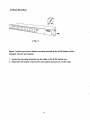
4.5 Rack Mounting
(Fig.7)
Figure 7 shows you how to attach mounting brackets to the KVM Switch unit for
standard 19-inch rack cabinet.
1.
Screw the mounting brackets into the sides of the KVM Switch unit.
2.
Slide the KVM Switch unit into the rack cabinet and secure it to the rack.
5. Hotkey Operation
The 8-Port or 16-Port Combo Free KVM Switch has the ability to switch the
keyboard, video, mouse simultaneously
Note: If vour Keyboard is without < Scroll Lock > button, please push
<Ctrl> twice, then <K>. and <Enter> to become <Caps Lock> button
instead of Scroll Lock.
5.1 Call OSD Menu
Press < Scroll Lock> twice and <Enter>, and then the OSD" Main Menuwill be on the screen.
Note: Hot-Key can be changed to become <Caps Lock>. (See page 20)
5.2 Channel Select
(Single KVM mode)
•
OSD: Use Up/Down arrow and <Enter> to select the channel directly.
•
Hot-Key via PS/2 and/or USB Keyboard
•
•
Press <Scroll Lock> twice, and then Keying a channel number (1 to 16 )
And then press <Enter>.
Left <Alt> or right <Alt> pushed twice, the PC channel will automatically
shift left/right one channel (channel decrease / increase to next),
while <Alt> enables.
<Alt> shift function default was off, and press Hot-Key <Alt> tw.ce, and
<Enter>. You can be on/off this function alternately. If buzzer was on, .t will
generate a beep for correct operating.
Hot Key:
[Scroll] - [Scroll]-[1]- [E^er]
or
[Scroll]- [Scroll]- [2]- [Enter]
or
.->
-■>
->
->
[Scroll]-[Scroll]-[161-[Enter]
5.9 Console unlock
•
OSD; Display the message only.
•
Hot-Key via PS/2 and/or USB Keyboard
Press any key into the Unlock window, and then enter the correct User
Name and Password. KVM and console device will unlock and be back to
normal operation.
6. Sun Micro System Function Key Emulation:
There are 16 special functions on the Sun Micro system keyboard, the Combo Free
KVM Switch can emulate these function keys via the PS/2 and/or USB keyboard.
Here is the mapping table for these functions operation. To active these emulation on
the PS/2 and/or USB keyboard, you have to press the LEFT Window KEY first (this
key usually is located between the left [Ctrl] and left [Alt]), do not release the lift
Window key choice the second relative key, and then release the two keys.
I6
7.
OSD Operation
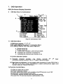
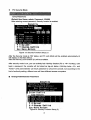
OSD (On-Screen-Display) Operation
•
OSD Main Menu for Administrator
1
Figure 8: Administrator OSD
7.1 OSD Main Menu
1.KVM layer number: 1st. 2nd, 3rd
2. PC name (defined by user): 31 characters (Max.)
3. PC Status: (Status: STA, See above figure 8)
4
Buzzer sound on
X Buzzer sound off
L Locked port indication, and normal is blank
9
s
Indicating the computer is powered on
Indicating the channel scan function is on
4. Current channel number
5. Cascade
channel
number:
only
display
cascade
2
connected channel number ; if it's in 1 layer, it will show blank.
,
3
layer
6. Page down-up indicator: (to next page) while connecting 16 port OSD KVM, it
will show up & down arrows alternatively to select previous/next page's port
number. (Only for 16-port KVM only.)
7.2 Function Control Menu
F1:
F2:
F3:
F4:
F5:
F6:
Set up: basic set up menu
Scan: autoscan function
Lock: setup lock/unlock, and available when F5 Security is set 'ON'
Rename: rename selected port name.
Security: security function and user priority setting
Lock Port: PC port lock function (administrator only)
17
•
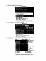
OSD Main Menu for Other User (1,2, 3)
1st ..":■,
10
=Select
Page On*
Post-BP
SScan Tag
Enter-Change
OSD Exit
Ft* Setup
:^can
=Logout
Ft-Lock Por*
Figure 9: User OSD
By pressing <Scroll Lock> twice and <Enter>, you will see an OSD 'Main Menu'
popped out in the screen with channel number, names and other status and other
function keys, please see figure 8 above. The channel of the currently selected
computer is displayed in the top right corner and a highlighted pink bar shown in the
selected channel row. The sign 5 is displayed if computer has power on and ready
for being selected (its corresponding front panel indicator is green).
If it doesn't
appear H sign, it means no computer connected or no powered up. OSD menu will
update the sign 5 when computer is activated.
Use the <UP> and <DOWN> arrow
keys to highlight a computer and the <ENTER> to select it and leave OSD menu. Or,
you can press <ESC> to exit OSD menu.
A plus mark (+) showing in the left of a name indicates that the port has cascades.
The number at the up-left corner (below KVM layer number) shows the number of
port for the upper layer, i.e. 8 means link from upper KVM 8. If in master layer it will
show blank.
<ENTER> brings you one level down and the screen pops up listing
the names of the computers on the Slave KVM. The name of the Slave will be
shown at the OSD menu. It is useful to group computers and still be able to see the
group name. Press <R> will return to upper layer OSD menu. Press <ESC> to
exit OSD and to return to the selected computer; the computer name is also shown
on the screen with a left-up banner.
• F1: Setup Mode
SttAlf
Scan Mode:$e:l:e;cf
Scan Time1
5Sec,
Banner Time:
5Soc.
Posi 11 on = Menu
Bannor
Hotkey:ScroU Lock
Sound:0N
Language:English(En)
♦ 4tChans« Sotting
Esc:Save,Return
Figure 10:
OSD Setup
All changes are enabled by left/right arrow key (—
■Scan Mode:
-») to select it.
Select - Scan selected channels in 'STA' column with 's' on OSD
main menu.
PC ON - Scan all powered-on PC channels only.
■Scan Time:
5 sec(Default) to 90 sec, 5 sec. a select step
■Banner Display Time: 5 sec. (Default), 10 sec, 15 sec, and always on (<x).
■Display Position: Menu - use four arrow keys to move the OSD main menu to the
desired position.
Banner - use four arrow keys to move the channel banner to the
desired position.
■Hot-Key: Scroll Lock - Scroll Lock becomes the Hot-Key.
Caps Lock - Caps Lock becomes the Hot-Key.
Ctrl - Ctrl is a defaulted Hot-Key.
Note: Scroll and Caos Lock are alternative. While Scroll Lock is enabled, if vou want
to alter the Hot-Kev to Caps Lock, you just press 'Scroll Lock' twice. K. and <enter>.
and vice versa.
■Sound: ON - Buzzer sound enabled. (Turn on)
OFF - Buzzer sound disabled. (Turn off)
■Language: English (En) / Deutsch (De) / Francais (Fr), 3 languages.
19
•
Position Adjustment
left
t move up
E::
■♦:move right
-J- move domn
Save,Return
Figure 11: Select Items to Setup
Into the banner Display Position, the display will become:
Channel Banner (Single Layer)
(Max. 22 characters)
-PC (Channel) Name
- Channel (PC) Number
PC powers on or change channel by OSD/Hot-Key, this banner will display 5 sec,
and disappear. User can change display time in the Setup Mode (F1).
Channel Banner
( Multi-Layer) (Max. 22 characters)
L
—
PC (Channel) Name
Channel (PC) Number
2nd Layer Channel (PC) Number
-1st Layer Channel (PC) Number
PC powers on or changes channel by OSD/Hot-Key, this banner will display 5sec.
and disappear. User can change display time in the Setup Mode (F1).
20
Channel Banner (Scan Mode)
{•JO..
fl
1—PC (Channel) Name
Channel (PC) Number
- Scan Mode
Stop scan: press any key.
Banner will disappear when the scan stops.
F4: Rename
(New Name: 31 characters Max)
-Select
CH
Name
0
Channel :03
0
Name:
UJeb
Serverl
9
9
Neui
Name;
0
Enter"Save New Name
Esc■Without Save.
Fl=Setup
F4;Rename
F2=Scan
F5,: Security
F3:Logout
FG^Lock Port
Figure 12: F4 Function Setup
21
F5: Security Mode
Entry Password:
(Default User Name: admin, Password: 123456)
After entering correct password, Security function is enabled.
Securi ty
Mode
Admi n/Password
Figure 13: Security Function Setup (1)
After the Security mode is 'ON' status, and F3 Lock Mode will be enabled automatically (it
will display on the Main Menu).
Also the Hot-Key Lock function (H) will be available.
After security mode is on, you can actively lock Hot-Key function (F3 or <H> Hot-Key), until
keyin a password, the console will be locked as log-out status. (Hot-Key twice, <H>, and
<Enter>) Only administrator can keyin password to unlock the console, but according to the
limit of authority setting, different user will have different access computers.
•
Change Administrator Password:
I
Security
Security
Mode:OFF
Admin/Passu)ord: I X/^
Neui
Password;
Confirm
Passuiord :
Enter=Confirm
Esc:Return
02
Mai I
03
Web
04
RD
server
Serverl
Soii tchl
t *sSelect
* '►••Change Setting
EecSave,Return
Figure14: Security Function Setup (2)
22
• Change User Name and Password:
Securi ty Mode:OFF
User Name:
PERRE-HELEN LEWIl[]
New
Password;
Confirm
Password;
Enter=Confirm
Esc:Return
03 UJeb Serverl
04
RO
Switch!
t +:Select
♦ ♦'Change Setting
Esc-Save,Return
Figure 15: Security Function Setup (3)
User PC Channel Authorization Setting
Security
Securi ty Mode:OFF
Admin/Passuiord:
Ch
Name
02
Mai I
03 UJeb
04
RD
server
tf
Serverl
o
Sum tchl
a
i
r
* *•Select
Esc-Save,Return
F6 Lock Port
Scan Tag
Enter:
Change
Esc •
OSD Exit
F4:Renane
FS^SecuMty
Figure16-17: Security Function Setup (4-5)
23
After PC port locked, "L" mark will show in its STA column until unlock status. (Select F6 and
keyin password again, and the PC port unlocks.)
F3 Console Lock Mode Banner:
Into the Security lock mode, this banner will display until Unlock status. The console device
and KVM button will lock (no any function could be enabled while back to unlock status); the
keyboard will just accept the correct password only. (Press any key into the unlock window.)
Unlock Window:
n
After key in a correct User Name and Password, the system will unlock (leave the Security
mode), screen will be into the normal and all devices are available to operate (according to
the authorization setting).
Note: If you forget the password, the only
way to permanently disable the security
function is to key in a universal password to
unlock KVM. You need to key in this unlock
password to release your device and KVM.
and then you can restart everything.
Universal password will let your KVM go back to defaulted administrator password, ask the
Universal password to your agency/distributor.
24
8. Troubleshooting :
25
Disclaimer
Information in this document is subject to change without notice. The manufacturer does not make any representations or
warranties (implied or otherwise) regarding the accuracy and connpleteness of this document and shall in no event be liable for
any loss of profit or any other commercial damage, including but not limited to special, incidental, consequential, or other
damages.
No part of this document may be reproduced or transmitted in any form by any means, electronic or mechanical, including
photocopying, recording or information recording and retrieval systems without the express written permission of the
manufacturer.
All brand names and product names used in this document are trademarks, or registered trademarks of their respective
holders.
FCC Statement
This device generates and uses radio frequency and may cause interference to radio and television reception if not installed
and used properly. This has been tested and found to comply with the limits of a Class B computing device in accordance with
the specifications in Part 15 of the FCC Rules. These specifications are designed to provide reasonable protection against such
interference in a residential installation. However, there is no guarantee that Interference will not occur in a particular installation.
If this device does cause harmful interference to radio or television reception, which can be determined by plugging the device
in and out, the user can try to correct the interference by one or more of the following measures:
•
Reorient or relocate the receiving antenna.
•
Increase the separation between the device and receiver.
•
Connect the computer into an outlet on a circuit different from that to which the receiver is connected.
•
Consult the dealer or an experienced radio/TV technician for help.
26