1
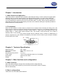
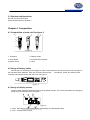
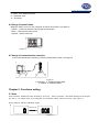
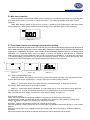
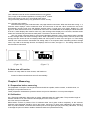
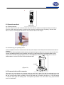
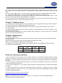
www.pce-industrial-needs.com
Tursdale Technical Services Ltd
Unit N12B
Tursdale Business Park
Co. Durham
DH6 5PG
United Kingdom
Phone: +44 ( 0 ) 191 377 3398
Fax: +44 ( 0 ) 191 377 3357
[email protected]
http://www.industrial-needs.com/
MANUAL PCE-HT200
[email protected]
Contents
Chapter 1. Introduction ............................................................................................................ 3 1.1 Main features and application ........................................................................................................ 3 1.2 Fundamental ................................................................................................................................... 3 Chapter 2. Technical Specification: ........................................................................................ 3 Chapter 3. Main functions and configuration .......................................................................... 3 3.1 Main functions ............................................................................................................................... 3 3.2 Basic configurations....................................................................................................................... 3 3.3 Optional configurations: ................................................................................................................ 4 Chapter 4. Composition ........................................................................................................... 4 4.1 Composition of main unit See figure 2 .......................................................................................... 4 4.2 Usage of battery house ................................................................................................................... 4 4.3 Usage of display screen ................................................................................................................. 4 4.4 Usage of press button ..................................................................................................................... 5 4.5 Usage of communication interface ................................................................................................ 5 Chapter 5. Functions setting .................................................................................................... 5 5.1 Start ................................................................................................................................................ 5 5.2 Max value function ........................................................................................................................ 6 5.3 Test times function and average value function setting ................................................................. 6 5.4 Auto turn off function .................................................................................................................... 7 Chapter 6. Measuring .............................................................................................................. 7 6.1 Preparation before measuring ........................................................................................................ 7 6.2 Calibration...................................................................................................................................... 7 6.3 Operation method........................................................................................................................... 8 6.4 Communication with computer...................................................................................................... 8 Chapter 7. Attention items ....................................................................................................... 9 Chapter 8. Maintenance .......................................................................................................... 9 Points for consumers attention ................................................................................................ 9 [email protected]
Chapter 1. Introduction
1.1 Main features and application
TIME TH210 Shore A hardness tester (hereafter called hardness tester) is a kind of advanced integral digital
hardness tester. It includes measuring device and data processing system. It is of the merit of advanced
technology, pocketsize, accurate measuring data, appearance beautiful, light weight, and easy to operate. It
can be connected with computer by RS-232 communication cable. It is mainly used to measure hardness of
hard plastic and rubber such as heat plasticity, hard resin, floor materials, bowling etc. Especially suitable for
finished products in working situation.
1.2 Fundamental
When the steel indenter of certain shape is pushed into the sample surface vertically with testing force, and
when surfaces of pressure foot and the sample touched completely (see figure 1), the indenter extends out for a
certain length “L” from the pressure foot plane. Greater length “L” means lower Shore hardness value and
smaller length “L” means bigger Shore hardness value. The formula is HA=100-L/0.025, HA is Shore A
hardness value in the formula.
The formula indicates that the hardness value is relevant to displacement of
indenter. Displacement of the indenter is measured by the sensor, then the value is given through calculation
and processing of the CPU.
I ndent er
No se puede mostrar la imagen. Puede que su equipo no tenga suficiente memoria para abrir la imagen o que ésta esté dañada. Reinicie el equipo y , a continuación, abra el archiv o de nuev o. Si sigue apareciendo la x roja, puede que tenga que borrar la imagen e insertarla de nuev o.
Pr essur e f oot
L
Sampl e
(Figure 1)
Chapter 2. Technical Specification:
Measuring range:
Measuring error within
Resolution:
Environmental temperature
Power supply
Dimensions:
Weight:
0HA 100HA
20HA 90HA, error ≤ ±1 HA
0.2HA
0 °C 40 °C
1.55V×3 button batteries and 5V AC- DC adapter
168mm×31mm×30mm
144g
Chapter 3. Main functions and configuration
3.1 Main functions
Peak value locked storage, average value calculating and low-voltage alarming.
Data communication with computer by use of RS-232 communication cable of company
Shut off automatically.
3.2 Basic configurations
TH200 main unit Three SR44 button batteries
[email protected]
3.3 Optional configurations:
RS-232 communication cable
Shore hardness stand of TH200FJ
Chapter 4. Composition
4.1 Composition of main unit See figure 2
No se puede mostrar la imagen. Puede que su equipo no tenga suficiente memoria para abrir la imagen o que ésta esté dañada. Reinicie el equipo y , a continuación, abra el archiv o de nuev o. Si sigue apareciendo la x roja, puede que tenga que borrar la imagen e insertarla de nuev o.
5
4
6
3
2
1
(Figure 2)
1. TH200unit
2. Display screen
3. Press button
4.Communication interface
5. Battery house
6. Hook
4.2 Usage of battery house
Pull out and turn the battery house slightly to make it rotate about 90° around axis with thumb, see figure 3.
Put into three button batteries. Take care of positive pole symbol “ ” consistently. At last, turn battery house
reversely until clamped closely with main unit, see figure 3.
No se puede mostrar la imagen. Puede que su equipo no tenga suficiente memoria para abrir la imagen o que ésta esté dañada. Reinicie el equipo y , a continuación, abra el archiv o de nuev o. Si sigue apareciendo la x roja, puede que tenga que borrar la imagen e insertarla de nuev o.
(Figure 3)
4.3 Usage of display screen
Screen is used to display results as well as working states of tester. The screen is divided into 5 displaying
areas which is stated as follow, see figure 4
No se puede mostrar la imagen. Puede que su equipo no tenga suficiente memoria para abrir la imagen o que ésta esté dañada. Reinicie el equipo y , a continuación, abra el archiv o de nuev o. Si sigue apareciendo la x roja, puede que tenga que borrar la imagen e insertarla de nuev o.
(Figure 4)
1---MAX Max value function (tester locked automatically and stored peak value),
2---AVE Average value function,
[email protected]
3---BATT Low-voltage indication,
4---Hardness value
5---Test times,
4.4 Usage of press button
Buttons is used to turn on or turn off power as well as set functions, see figure 5:
N/AVE---- Test times function and Average function button,
MAX------Max value function button
ON/OFF---Switch button red.
No se puede mostrar la imagen. Puede que su equipo no tenga suficiente memoria para abrir la imagen o que ésta esté dañada. Reinicie el equipo y , a continuación, abra el archiv o de nuev o. Si sigue apareciendo la x roja, puede que tenga que borrar la imagen e insertarla de nuev o.
(Figure 5)
4.5 Usage of communication interface
It can communicate with computer by RS-232 communication cable. See figure 6.
No se puede mostrar la imagen. Puede que su equipo no tenga suficiente memoria para abrir la imagen o que ésta esté dañada. Reinicie el equipo y , a continuación, abra el archiv o de nuev o. Si sigue apareciendo la x roja, puede que tenga que borrar la imagen e insertarla de nuev o.
1
2
3
4
(Figure 6)
1. Computer 2. Communication cable
3. sample 4. Hardness tester
Chapter 5. Functions setting
5.1 Start
Press bu tto n ON /O ff-scr een disp la ys “0” firs tly a fter sec onds , th e da ta d isp la yed ch an ged
as “00.0”. At same time, the program of hardness tes ter s tarts to work , see figure 7.
Press sw itch bu tto n ON /OF F aga in ,
No se puede mostrar la imagen. Puede que su equipo no tenga suficiente memoria para abrir la imagen o que ésta esté dañada. Reinicie el equipo y , a continuación, abra el archiv o de nuev o. Si sigue apareciendo la x roja, puede que tenga que borrar la imagen e insertarla de nuev o.
Few seconds
(Figure 7)
[email protected]
5.2 Max value function
Press MAX button, screen displays MAX symbol, see figure 8. The value is the maximum of once test (auto
locks peak value function). If you want to cancel this function, only need to press MAX again (MAX symbol
vanishes).
Under MAX situation (when do not set Ave. function), it needs to press button MAX to clear zero before
next measurement ( MAX symbol vanishes correspondingly), then press MAX again to start measuring.
No se puede mostrar la imagen. Puede que su equipo no tenga suficiente memoria para abrir la imagen o que ésta esté dañada. Reinicie el equipo y , a continuación, abra el archiv o de nuev o. Si sigue apareciendo la x roja, puede que tenga que borrar la imagen e insertarla de nuev o.
(Figure 8)
5.3 Test times function and average value function setting
Press down button N/AVE (the MAX function do not be set), the “00.0” vanishes and displays AVE symbol at same time as
well as display test times on right bottom corner ( before setting, it displays the test times to be set last time, the test times is
supposed as 7 on illustration), see figure 9. At this moment, the test times setting should be carried on. The setting method
sees below 5.3.1. Supposed setting value is 3 shown on screen, see figure 10 seconds later of completed
setting, displaying area restore hardness value as “00.0” and test times changed as “0” at same time, see figure
11 It indicates setting successful and can be put into measuring situation. If want to cancel this function, only
need to press button N/AVE again, AVE symbol and test times vanishes at this moment.
No se puede mostrar la imagen. Puede que su equipo no tenga suficiente memoria para abrir la imagen o que ésta esté dañada. Reinicie el equipo y , a continuación, abra el archiv o de nuev o. Si sigue apareciendo la x roja, puede que tenga que borrar la imagen e insertarla de nuev o.
No se puede mostrar la imagen. Puede que su equipo no tenga suficiente memoria para abrir la imagen o que ésta esté dañada. Reinicie el equipo y , a continuación, abra el archiv o de nuev o. Si sigue apareciendo la x roja, puede que tenga que borrar la imagen e insertarla de nuev o.
No se puede mostrar la imagen. Puede que su equipo no tenga suficiente memoria para abrir la imagen o que ésta esté dañada. Reinicie el equipo y , a continuación, abra el archiv o de nuev o. Si sigue apareciendo la x roja, puede que tenga que borrar la imagen e insertarla de nuev o.
(Figure 9)
(Figure 10)
(Figure 11)
5.3.1 Setting methods of test times
Under figure 9state, the test times can be set by press button N/AVE continually. The max test times are 9,
in which the times can be circled within 0 9 range. There are two kinds of setting method:
Method 1 Press button N/AVE for a while, the times circulated among 0 9 range until it reaches
requirement, then release button at once and completed.
Method 2 Press button N/AVE repeatedly. The value adds one for every times press in which the times
circulated among 0 9 range until reaches requirement, then release button at once and completed.
After completed test times setting, machine is in ready state for testing, see figure 11.
GAS Arrester Testing.
Today, most equipments and electrical installations are protected by MOVs and GAS arresters.
The Multifunction Tester can test these devices to establish if the devices are still operating correctly or not.
Energy conservation is featured on all these new Advanced Products.
TM
EnerSave limits the test duration to about 10 Seconds to save energy.
This new generation of test equipments has no moving parts. All calibration are saved internally in a non volatile
memory.
Calibration can be done at any calibration facility around the world, without the need for dedicated calibration
equipment.
This makes these products easier to maintain and lower the cost of calibration and ownership.
[email protected]
Their calibration interval can be extended without much problem.
Th
They comply to all the latest regulations, including UK 16 Edition.
This product family is part of our new World Class series.
They prominently feature heavy duty protections in their circuitry.
5.3.2 Average value setting:
After test times being set, hardness tester can judge based on test times. When test times are among 3 9,
hardness tester displays current measured value and test times of this test. When reached the set times,
automatically cancels rough error and displays average value. If rough error is too larger, displays “E.”, see
figure 12. When test times is set as 2, arithmetical mean of the two tested data will be displayed. When test times
is set as 1, tester displays the measure value only. After average value displays for 8 seconds, hardness tester
clears zero automatically and restores ready state. The times to be set are still valid.
User can record measured data by manual and calculates arithmetic mean. The average value is divided
as max average value and random average value. When calculating max average value, the max function and
average function should be set and displays MAX and AVE symbol at same time; see figure 13. Their setting
method is the same as above mentioned and setting order is not required. When calculating random average
value, only need to set average function and displays AVE on screen, see figure 11. The setting method is the
same as above mentioned
No se puede mostrar la imagen. Puede que su equipo no tenga suficiente memoria para abrir la imagen o que ésta esté dañada. Reinicie el equipo y , a continuación, abra el archiv o de nuev o. Si sigue apareciendo la x roja, puede que tenga que borrar la imagen e insertarla de nuev o.
No se puede mostrar la imagen. Puede que su equipo no tenga suficiente memoria para abrir la imagen o que ésta esté dañada. Reinicie el equipo y , a continuación, abra el archiv o de nuev o. Si sigue apareciendo la x roja, puede que tenga que borrar la imagen e insertarla de nuev o.
(Figure 12)
(Figure 13)
5.4 Auto turn off function
If tester is in ready state for three minutes, and flashes on
Screen for fifteen seconds then turns off automatically.
Chapter 6. Measuring
6.1 Preparation before measuring
The preparation of sample: The sample thickness should be equable, surface smooth, no bubble inner, no
damaged, no impurities and so on.
Tester preparation: disassemble protective sleeve and put into batteries or connect power adapter.
6.2 Calibration
6.2.1 Zero point calibration: After switch on power, hardness tester is in ready state. The protrusion length of
indenter needle is max; the hardness value displayed on the screen is zero.
6.2.2 Non zero point calibration
Make bottom surface of pressure foot of hardness tester touch glass surface completely. At this moment,
hardness value displayed should be 100 on the screen, see figure 14. Note: when calibrating in this method, in
order to protect indenter, it should avoid indenter point to touch glass promptly and rudely. Otherwise, it is easy
to damage the point of indenter needle of hardness tester and operate abnormally.
[email protected]
No se puede mostrar la imagen. Puede que su equipo no tenga suficiente memoria para abrir la imagen o que ésta esté dañada. Reinicie el equipo y , a continuación, abra el archiv o de nuev o. Si sigue apareciendo la x roja, puede que tenga que borrar la imagen e insertarla de nuev o.
6.3 Operation method
6.3.1 Manual measure:
Place the sample on the slab. Hold the tester and press indenter needle into sample vertically and slowly to
avoid any shake. When the bottom of pressure foot touches the sample surface completely, read the value
within 1 second. The displayed value then is the hardness value of the sample.
(Figure 15)
6.3.2 Measuring by the operating stand:
A After completed connection of hardness tester with stand, place sample on work table (see shore hardness tester stand of
TH200FJ)
B Assemble the balancing weight with balancing fixing rod together through its middle hole. Then press down handle, at this
moment, work table and sample move up together, see (figure 16). When pressure foot of the hardness tester touches
sample surface and balancing weight slightly moves up, the testing state is reached. Read the display data on screen of
hardness tester in 1 second. This value is Shore A hardness value.
No se puede mostrar la imagen. Puede que su equipo no tenga suficiente memoria para abrir la imagen o que ésta esté dañada. Reinicie el equipo y , a continuación, abra el archiv o de nuev o. Si sigue apareciendo la x roja, puede que tenga que borrar la imagen e insertarla de nuev o.
sample
(Figure 16)
6.4 Communication with computer
This tester can communicate with computer which the band rate is 9600. The data is transferred by text file
which can receive by common communication software (such as super technical device of WINDOWS). The
RS-232 communication cable is needed to connect the tester with a computer, see figure 6. It can send signal
to computer when gets the reading value. The operation procedure is as follow when using super terminal
device of WINDOWS:
[email protected]
6.4.1 Connect the nine cores bottom of RS-232 communication cable to series interface of computer. Insert the
other bottom into communication interface of hardness tester (series interface), see figure 6. Switch on the
tester.
6.4.2 Click “start”
“program”
“Accessories”
“communication” on WINDOWS to HyperTerminal.
6.4.3 Run HyperTerminal, type in a file name at new established connection, then press “Enter”.
6.4.4 Select the series interface of communication cable, then select band rate 9600, press “Enter”. At this
moment, the measured value should be displayed on computer.
6.4.5 If you want to store the measured result, select “Disconnect” under “dial” menu of HyperTerminal, select
“save as” under “file” menu. Type in a file’s name. That is OK.
Chapter 7. Attention items
7.1. The indenter of hardness tester is sharp cone, forbid to touch it with glass plate forcely in order to protect it.
Otherwise, it is easy to be damaged and to operate abnormally.
7.2. Forbid hardness tester collision and fall break. After service, pull on protective sleeve so as to protect
the indenter needle.
7.3. When displays symbol BATT in low-voltage, see figure 8, replace batteries in time and pay attention to the
pole of batteries, see figure 5.
7.4 After completed measurement by using operating stand, see figure 7, close the joint cover of hardness
tester so as to avoid dust entering into.
Chapter 8. Maintenance
8.1. Routine maintenance
This hardness tester should avoid impact and heavy loading, and keep away from strong magnetic field, damp
or oil environment.
If store for long time and do not use it, take out batteries and take care of them.
When do not using the tester, please put it into packing box.
8.2. Maintenance. If any abnormal phenomenon occurs, please contact the service maintenance centre of company.
8.3. The list of non maintenance parts
Items
Name
Quantity
1
Indenter needle
1
2
Button battery
3
Remarks
Points for consumers attention
1. From purchased date, the products occur any fault except for non guarantee maintenance parts, will free
maintain by warranty card and invoice copy within one year. If you could not show above mentioned
requirement, company calculates guarantee period in accordance with the date of leaving factory, valid period is
one year.
2. If the fault product exceeds maintenance period, in accordance with stipulation of Company, it will be taken
charge of maintenance and service.
3. The “special configuration” out of Company’s approved products would take fees in accordance with related
standards.
4. The product should not receive free maintenance service if belongs to conditions as follow: storage
unsuitable, operated incorrectly which is not in accordance with manual book, disassembled, altered by oneself
as well as no purchasing proof.
In this direction will find a vision of the measurement technique:
http://www.industrial-needs.com/measuring-instruments.htm
NOTE: "This instrument doesn’t have ATEX protection, so it should not be used in potentially explosive
atmospheres (powder, flammable gases)."