1
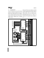
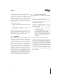
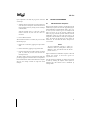
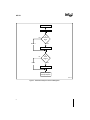
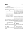
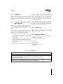
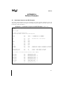
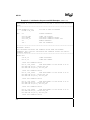
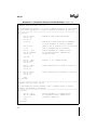
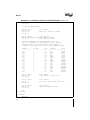
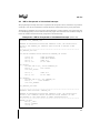
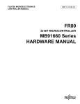
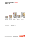
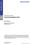
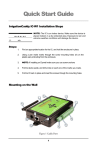
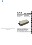
A
AP-731
APPLICATION
NOTE
Understanding the Interrupt
Control Unit of the
80C186EC/80C188EC
Processor
Sean Kohler
Application Engineer
Intel Corporation
5000 West Chandler Boulevard
Chandler, AZ 85226
March 13, 1996
Order Number: 272823-001
Information in this document is provided in connection with Intel products. Intel assumes no liability whatsoever, including infringement of any patent or copyright, for sale and use of Intel products except as provided in Intel’s Terms and Conditions of
Sale for such products.
Intel retains the right to make changes to these specifications at any time, without notice. Microprocessor products may have
minor variations to this specification known as errata.
*Other brands and names are the property of their respective owners.
Contact your local Intel sales office or your distributor to obtain the latest specifications before placing your product order.
Copies of documents which have an ordering number and are referenced in this document, or other Intel literature, may be obtained from:
Intel Corporation
Literature Sales
P.O. Box 7641
Mt. Prospect, IL 60056-7641
or call 1-800-548-4725
COPYRIGHT © INTEL CORPORATION, 1996
A
Contents
Understanding the Interrupt Control Unit of the
80C186EC/80C188EC Processor
1.0 INTRODUCTION ........................................................................................................................................1
2.0 OVERVIEW ................................................................................................................................................2
3.0 INTERRUPT PROCESSING ......................................................................................................................2
4.0 82C59A PROGRAMMING .........................................................................................................................3
4.1 ICW Initialization Sequence ................................................................................................................3
4.2 Initialization Command Words ............................................................................................................5
4.2.1 ICW1 Beginning of Initialization Register .................................................................................5
4.2.2 ICW1 Access ...........................................................................................................................6
4.2.3 ICW2 Base Interrupt Type Register .........................................................................................6
4.2.4 ICW2 Access ...........................................................................................................................6
4.2.5 ICW3 Cascaded Input Selection/Slave ID ................................................................................7
4.2.6 ICW3 Access ...........................................................................................................................7
4.2.7 ICW4 Special Fully Nested Mode/ Automatic End of Interrupt Mode Register ........................7
4.2.8 ICW4 Access ...........................................................................................................................7
4.3 Operational Command Words ............................................................................................................7
4.3.1 OCW1 Interrupt Mask Register ................................................................................................7
4.3.2 OCW1 Access ..........................................................................................................................7
4.3.3 OCW2 Priority and EOI Register ..............................................................................................7
4.3.4 OCW2 Access ..........................................................................................................................8
4.3.5 OCW3 Special Mask Mode and Read Register Selection .......................................................8
4.3.6 OCW3 Access ..........................................................................................................................8
5.0 RELATED INFORMATION .........................................................................................................................8
APPENDIX A Software Examples ............................................................................................................. A-1
A.1 Initialization Sequence and ISR Examples ..................................................................................... A-1
A.2 ISR for Unexpected or Uninitialized Interrupts ............................................................................... A-9
FIGURES
Figure 1.
Interrupt Control Unit Block Diagram ........................................................................................ 1
Figure 2.
Initialization Sequence of the ICW Registers............................................................................ 4
TABLES
Table 1.
A1 Address Line Connections ................................................................................................... 5
Table 2.
Related Information ................................................................................................................... 8
EXAMPLES
Example A-1. Initialization Sequence and ISR Examples ............................................................................ A-1
Example A-2. ISR for Unexpected or Uninitialized Interrupts ....................................................................... A-9
iii
A
INTRODUCTION
The Intel 186 processor core has two external interrupt
sources; the Non-Maskable Interrupt (NMI) and a maskable
interrupt source (INTR). The NMI input of the core is
brought directly out to the NMI pin. For most embedded
designs, a single maskable interrupt input is not sufficient.
In order to expand the capabilities of the single maskable
interrupt an interrupt controller is needed. Most of the 186
embedded processor proliferations use a proprietary
interrupt controller to expand the number of available
maskable interrupts.
Unlike other members of the 186 family of embedded
microprocessors, the 80C186EC/80C188EC processor uses
an 82C59A compatible interrupt control unit instead of a
proprietary interrupt controller. (The 82C59A is an industry
standard interrupt controller for embedded and PCcompatible solutions.) Two 82C59A compatible programmable interrupt controllers (PIC) are located on the
80C186EC/80C188EC processor die. One PIC is
configured as the master while the other is configured as a
slave. The slave is connected to IR7 of the master. See
Figure 1.
Master 8259A
IR0
IR1
IR2
IR3
IR4
IR5
IR6
IR7
INT
INTA
D7:0
Slave 8259A
INT
IR0
IR1
IR2
IR3
IR4
IR5
IR6
IR7
Internal Control Bus
CAS2
CAS1
CAS0
Internal Interrupt
Request Latch
Registers
INTA
D7:0
A0
A1
CAS2
CAS1
CAS0
TMI0
TMI1
DMA12
DMA13
TMI2
RXI0
TXI0
INT7
A1
A0
Internal Address Bus
INT0
INT1
INT2
INT3
INT4
INT5
INT6
INT7
Internal Data Bus (F-Bus)
1.0
AP-731
CAS Bus
Interrupt Requests From Integrated Peripherals
Figure 1. Interrupt Control Unit Block Diagram
1
A
AP-731
The 82C59A has eight interrupt request lines. By cascading
additional 82C59As, up to 64 interrupt request lines can be
supported. Each cascaded 82C59A is called a slave; there
can be only one master. The master PIC of the
80C186EC/80C188EC processor prioritizes interrupt
requests from attached slaves and IR lines and presents
requests, one at a time, to the single maskable interrupt line
of the processor core.
3.0
When an interrupt occurs, several steps are taken by the
processor:
1.
A partial machine status is saved/copied by pushing the
Program Status Word (PSW) onto the stack.
2.
The Trap Flag (TF) bit and the Interrupt Enable Flag
(IF) bit are cleared in the PSW.
This application note contains:
•
A step-by-step description of the interrupt processing
sequence.
•
A description of subtleties
programming 82C59A registers.
associated
This prevents maskable interrupts or single step
exceptions from interrupting the processor during the
ISR. While in the ISR:
with
This application note is meant to be used in conjunction
with the 80C186EC/80C188EC Microprocessor User’s
Manual. Refer to the User’s Manual for a complete
explanation of the operation of 82C59A registers.
2.0
OVERVIEW
The 80C186EC/80C188EC processor can detect up to 256
different interrupts. Each interrupt is specified by its
interrupt type ranging from 0 to 255. Each interrupt type has
a corresponding interrupt vector, which is the interrupt type
multiplied by 4. A vector is a double word pointer that
points to the associated Interrupt Service Routine (ISR). An
interrupt vector table in memory stores up to 256 interrupt
vectors. The first word of the vector contains the offset of
the associated ISR while the second word contains the
segment. This makes each vector a total of 4 bytes. The
interrupt vector table is located at the base of the
processor’s memory map, at 0000:0000. The interrupt
vector table is 1 Kbyte in length (4 bytes multiplied by 256
types) and therefore goes up to 0000:03FF. Because of the
location of the interrupt vectors, the lower 1 Kbyte of
memory space should be reserved for interrupt vectors.
2
INTERRUPT PROCESSING
•
To nest interrupts, set the IF bit in the PSW by
issuing an STI instruction.
•
To use single stepping inside an ISR, push/copy
the PSW onto the stack using the PUSHF
instruction, modify the copy of the PSW on the
stack to set the TF bit and then restore the PSW
by popping the altered copy off of the stack
using POPF.
3.
The current CS and IP are pushed onto the stack.
4.
The interrupt controller passes the interrupt type to the
processor. The processor multiplies the interrupt type
by 4 to yield the base address of the associated interrupt
vector. The processor reads a word from that address
and loads it into the IP register. It then reads the next
word at the interrupt vector address plus 2 and loads the
value into the CS register. The processor begins
executing code at the new location specified by CS and
IP. This location is the ISR associated with the
particular interrupt.
A
AP-731
Upon completion of the ISR, the programmer must take
several steps:
4.0
1.
4.1
When the interrupt comes from one of the request lines
of the PIC (not an exception), clear the In-Service bit
for that interrupt source by issuing an end of interrupt
command (EOI).
When the interrupt source is a slave PIC, clear the
master’s In-Service bit, then clear the slave’s InService bit.
2.
Issue an IRET instruction.
When an IRET instruction is executed, the processor takes
the following steps:
1.
Restores the CS and IP by popping the copies off the
stack.
2.
Restores the PSW by popping its copy off the stack.
3.
Executes instructions at the address that the CS and IP
point to (where the processor left off before the
interrupt occurred).
The stack is used to store the pre-interrupt flag status and
pre-interrupt program execution location. It is important to
locate and allocate the stack such that data/code corruption
does not occur during execution of single and nested
interrupts.
82C59A PROGRAMMING
ICW Initialization Sequence
Before normal operation can begin, each 82C59A must be
initialized by a sequence of two to four programming bytes
called Initialization Command Words (ICWs). After reset,
the states of all the 82C59A registers are undefined. The
ICWs are used to set up the necessary conditions and
modes for proper 82C59A operation. Minimum 82C59A
initialization requires at least ICW1 and ICW2 to be
configured. ICW3 and ICW4 are used only if designated in
ICW1. The details of the function of each register are
described in the 80C186EC/80C188EC Microprocessor
User’s Manual.
NOTE:
The ICW initialization sequence is started (or
restarted) at ICW1 by writing data to master port
MPICP0 or slave port SPICP0 with the data bit
position 4 set to a 1.
Figure 2 illustrates the initialization sequence of the ICW
registers. The sequence in which these registers are
programmed is critical.
Once the 82C59A is initialized, any changes to the ICWs
are made by restarting the sequence. If the sequence is
interrupted, the state machine can be reinitialized by
writing to ICW1.
3
A
AP-731
ICW1
ICW2
No
In
Cascade
Mode
?
Yes
SNGL=1
ICW3
No
IC4=0
Is
ICW4
Needed
?
Yes
ICW4
Ready to Accept
Interrupt Requests
A4327-01
Figure 2. Initialization Sequence of the ICW Registers
4
A
AP-731
Once the initialization sequence begins (ICW1 has been
accessed), the 82C59A automatically performs the
following events:
•
•
Table 1. A1 Address Line Connections
Port Name
PCB Offset
A1 of Processor
A0 of 82C59A
MPICP0
00
0
MPICP1
02
1
SPICP0
04
0
SPICP1
06
1
The edge sense circuit is reset, which makes low to
high transitions on the interrupt request (IR) line
necessary for a valid interrupt.
The interrupt mask register is cleared to allow
interrupts on all IR lines to be processed. Since initialization is not yet completed, it is strongly
recommended that all maskable interrupts be masked
during initialization by issuing a CLI instruction. The
CLI instruction masks off the single maskable interrupt
source on the 8086 enhanced core. Since the 82C59A
presents interrupt requests via the single maskable
interrupt input, any request coming through any of the
PICs will be masked when the CLI instruction is
executed. Once initialization is complete, an STI
instruction can be used to enable interrupts.
•
IR7 input is assigned the highest priority.
•
The slave mode address is set to 7.
•
Special Mask Mode is cleared and Status Read is set to
IRR.
The first character of the port name indicates which internal
82C59A port is referenced: “M” indicates the Master PIC
and “S” indicates the Slave.
4.2
Initialization Command Words
The Initialization Command Words (ICWs) are
programmed in a sequential format and are used to set up
the integrated interrupt controller to an initial state of
operation. Typically, the ICW registers are programmed
only once and are left untouched for the duration of the
application. This section highlights some of the subtleties
associated with the functionality of each register and with
accessing each register.
NOTE:
For the 80C186EC processor, the SNGL bit should
always be cleared (leading to initialization of ICW3)
and the IC4 bit should always be set (leading to
initialization of ICW4).
The complex initialization sequence exists because the
original 8259 was designed with only one address line.
Without the use of an initialization sequence (state
machine), a device with only one address line would be
able to access only two registers (ports). By implementing
an initialization sequence, designers could keep the chip
small and still access more than two registers (using only
one address line).
Write accesses to the Initialization Command Words of the
82C59A are controlled by the following:
•
The state of the A0 line of the 82C59A (which port
being accessed)
•
The data written to the register
•
The sequence in which the data is written
The A0 line of the 82C59A is connected to the A1 address
line of the 80C186EC/80C188EC processor. See Table 1.
4.2.1
ICW1 Beginning of Initialization
Register
ICW1 is used to select level or edge sensitive triggering on
the IRQ lines, the number of 82C59As in the system and to
indicate whether or not the ICW4 register is used in the
initialization sequence.
NOTE:
Mixed mode triggering is not possible. Either all of
IR0 through IR7 is level triggered or edge triggered,
but not both.
There are some subtle differences between edge and level
sensitive interrupts. If an IRQ line is configured as level
sensitive and is left asserted while it is serviced, the
processor immediately vectors back into the ISR once the
EOI is issued. Therefore, if configured as level sensitive,
the IR line must be deasserted before issuing the EOI
command inside the ISR. If the IR line is configured as
edge sensitive, the processor will not vector back into the
ISR if the IR line is kept asserted once the EOI has been
issued. In order for another interrupt to occur on a edge
sensitive IR line, the line must be brought to its inactive
state for 100 ns to reset the edge detection circuitry.
5
A
AP-731
4.2.2
ICW1 Access
ICW1 is a write-only register that is accessed through
MPICP0 or SPICP0 with data bit position 4 set. See “ICW
Initialization Sequence” on page 3 for more details.
4.2.3
ICW2 Base Interrupt Type Register
The data written to this register corresponds to the base
interrupt type. The base interrupt type is synonymous with
the interrupt type for IR0. Once the base type has been
defined each subsequent IRn line will have a TYPE =
BASE + n. The interrupt vectors for each IR line will be at
the location TYPE*4 in memory.
When an IR line is configured as a cascaded input, it still
has an associated type (interrupt vector), but in most cases,
it is not used.
There is a case in which an IR line configured as Cascade
Mode still uses its corresponding interrupt vector. This
special case exists when IR7 is configured for Cascade
mode and it is also used for spurious interrupt detection. If
any IR line is asserted and is deasserted before the falling
edge of the first interrupt acknowledge pulse, then a special
interrupt called a “spurious interrupt” is generated. The
82C59A detects these spurious interrupts when an IR line is
asserted in this manner, and generates an interrupt of type
IR7. The only difference between a true IR7 interrupt and
an interrupt caused by a spurious interrupt detection is the
fact that when a spurious interrupt is acknowledged, the InService bit for IR7 is never set. Spurious interrupt detection
is useful in noisy environments where unwanted glitches
might be interpreted as valid interrupt assertions.
If IR7 is configured for Cascade mode then an interrupt of
type IR7 can occur if a spurious interrupt was detected on
one of the IRn lines of the PIC. If configured for Cascade
6
mode and a spurious interrupt does occur, a typical IR7 ISR
(spurious interrupt ISR) simply returns control back to the
main program by issuing an IRET instruction. See
Appendix A for details
If IR7 is being used and it is not configured in Cascade
Mode, then there are two possibilities for an interrupt of
type IR7 to occur:
•
A valid IR7 interrupt occurred
•
A spurious interrupt was detected on one of the IRn
lines of the PIC
If not configured for Cascade mode, once inside the IR7
ISR, software must examine the In-Service register to
determine what event caused the processor to enter the ISR.
If the In-Service bit for IR7 is set, then a valid IR7 interrupt
occurred. If the In-Service bit is not set, then a spurious
interrupt must have occurred on one of the eight IR lines of
the PIC. Once the software has determined that it is inside
the IR7 ISR because of a spurious interrupt, most ISRs just
issue an IRET instruction to return control back to the main
program. If the processor is inside the IR7 ISR because of a
valid interrupt, the interrupt is serviced, its In-Service bit is
cleared by issuing a End of Interrupt (EOI) then finally the
ISR is completed and control returned back to the main
program by issuing a IRET instruction. See Appendix A for
an example.
4.2.4
ICW2 Access
ICW2 is a write-only register which is accessed by a write
to MPICP1 or SPICP1 immediately after ICW1 has been
configured. See “ICW Initialization Sequence” for more
details.
A
4.2.5
AP-731
ICW3 Cascaded Input
Selection/Slave ID
ICW3 of the master is used to select whether or not a slave
will be connected to the associated IR line.
ICW3 of a slave is used to set the associated slave ID. The
slave ID should match the IR line number of the master that
it is connected to.
NOTE:
Special precautions must be taken when connecting
a slave to IR0 of a master 82C59A module. A slave
programmed for an ID of zero will be active for both
interrupts that it has requested, as well as for
uncascaded master interrupts; uncascaded interrupts
leave the cascade bus (CAS2:0) lines low. If this
situation occurs there will be contention on the data
bus, since both the master and the slave attempt to
drive the interrupt type on the data bus. Never
cascade a slave 82C59A module to IR0 of a master
module unless IR0 is the last available uncascaded
input (i.e., the system is fully cascaded with eight
slave 82C59A modules).
4.2.6
ICW3 Access
ICW3 is a write-only register. If the SNGL bit of ICW1 was
cleared during the initialization sequence, ICW3 can be
accessed by a write to MPCIP1 or SPCIP1 immediately
after ICW2 has been initialized. See “ICW Initialization
Sequence” for more details.
4.2.7
ICW4 Special Fully Nested Mode/
Automatic End of Interrupt Mode
Register
4.3
Once the 82C59A has been initialized using the ICWs, the
Operational Command Words (OCWs) can be used to
modify priority schemes, End of Interrupt (EOI) configurations and interrupt masking.
Three OCWs are available for programming but, unlike the
ICWs, the OCW registers can be accessed in any order.
These registers can be accessed whenever the programmer
desires, provided that the ICWs have been previously
initialized. Although there is no accessing sequence to the
OCWs, accessing each OCW and accompanying register
(described later) is not intuitive. A detailed description of
the OCW registers is given in the 80C186EC/80C188EC
Microprocessor User’s Manual. This section highlights
some of the subtleties associated with the function of each
register and with accessing each register.
4.3.1
4.2.8
OCW1 Interrupt Mask Register
OCW1 is the interrupt mask register. Setting a bit in the
mask register disables the corresponding interrupt request
on the associated IR line.
It is important to note that if the IR line is asserted while it
is masked, the associated interrupt request bit will be set,
but the interrupt will never be presented to the processor
core because it is masked. If an IR line is unmasked while
the interrupt request bit is set, the interrupt request will be
presented to the processor core. Therefore, it is important to
clear the associated interrupt request bit when masking and
unmasking interrupts. The interrupt request bit can be
cleared by reading the interrupt request register (see
“OCW3 Special Mask Mode and Read Register
Selection”).
4.3.2
ICW4 is a write-only register. Special Fully Nested (SFN)
Mode and Automatic End of Interrupt (AEOI) Mode are
selected using ICW4.
Operational Command Words
OCW1 Access
OCW1 is accessed by read or writes to SPICP1 or MPICP1
provided that the ICW initialization sequence has been
completed.
ICW4 Access
4.3.3
ICW4 is accessed by a write to MPICP1 or SPICP1
provided that the IC4 bit was set in ICW1 during the initialization sequence. See “ICW Initialization Sequence” for
more details.
OCW2 Priority and EOI Register
OCW2 is used to set interrupt priority schemes and various
End of Interrupt (EOI) configurations. A detailed
description of its operation is in the 80C186EC/80C188EC
Microprocessor User’s Manual.
7
A
AP-731
4.3.4
OCW2 Access
OCW2 is a write only register that is accessed by writes to
MPICP0 or SPICP0 with data bit position 3 and 4 cleared
provided that the ICW initialization sequence has been
completed.
4.3.5
OCW3 Special Mask Mode and Read
Register Selection
OCW3 is used to control Special Mask Mode, Poll Mode
and read register selection. A detailed explanation is given
in the 80C186EC/80C188EC Microprocessor User’s
Manual.
Setting the ERR bit in conjunction with either clearing or
setting the RSEL bit determines which register is accessed
through a read cycle to the MPICP0 or SPICP0 port.
•
•
The In-Service register is an 8-bit register containing the
priority levels that are being serviced. The In-Service
register is updated when an End of Interrupt (EOI)
command is issued. Once the In-Service bit is set, assertions
to the corresponding IR line will be ignored until it is
cleared (by issuing an EOI).
The Interrupt Request register is an 8-bit register containing
the priority of the interrupts waiting to be acknowledged.
The highest request level is reset from the Interrupt Request
register when an interrupt is acknowledged.
4.3.6
OCW3 Access
OCW3 is a write only register that is accessed by writing to
MPICP0 or SPICP0 with data bit position 3 set and data bit
positions 4 and 7 cleared.
If the OCW3 register is written to and the RSEL bit is
set in conjunction with the ERR bit, then a read to
either MPICP0 or SPICP0 will be a read to the InService register.
5.0
If the OCW3 register is written to and the RSEL bit is
cleared in conjunction with the ERR bit, then a read to
either MPICP0 or SPICP0 will be a read to the Interrupt
Request register.
To order printed Intel literature, contact:
The RSEL bit can only be modified when the ERR bit is set.
RELATED INFORMATION
Intel offers a variety of information through the World Wide
Web at http://www.intel.com.
Intel Corporation
Literature Fulfillment
P.O. Box 7641
Mt. Prospect, IL 60056-7641
1-800-548-4725
Table 2. Related Information
Document Name
Order #
80C186EC/80C188EC Microprocessor User’s Manual
272047
Embedded Microprocessors Databook
see the 80C186EC/80C188EC and 80L186EC/80L188EC 16-Bit High-Integration
Embedded Processors datasheet
272396
Peripheral Components Databook
see the 82C59A-2 CHMOS Programmable Interrupt Controller datasheet
296467
8
A
A.1
AP-731
APPENDIX A
Software Examples
Initialization Sequence and ISR Examples
This software example illustrates interrupt vector initialization, basic interrupt controller initialization sequence and
simple interrupt service routines. This software was assembled using Intel ASM86 and was tested using the Intel
EV80C186EC evaluation board REV 1.1.
Example A-1. Initialization Sequence and ISR Examples (Sheet 1 of 8)
$ TITLE (82C59 Programming Example)
$ MOD186
NAME ICU_DEMO
$INCLUDE (C:\EV186EC\ECPCB.INC)
;INCLUDE PERIPHERAL CONTROL BLOCK REGISTER MAP
_7SEG1
_7SEG2
EQU
EQU
1000H
1010H
;7 SEGMENT #1 I/O ADDRESS
;7 SEGMENT #2 I/O ADDRESS
ZERO
ONE
TWO
THREE
FOUR
FIVE
SIX
SEVEN
PATTERN1
PATTERN2
EQU
EQU
EQU
EQU
EQU
EQU
EQU
EQU
EQU
EQU
03FH
06H
05BH
04FH
066H
06DH
07CH
07H
064H
052H
;BIT MAPS FOR 7 SEG DISPLAY
MASTER_BASE_TYPE
SLAVE_BASE_TYPE
EQU
EQU
96
104
;TYPE*4 = BASE ADDR OF MASTER
;TYPE*4 = BASE ADDR OF SLAVE
;IDENTIFIES SPURIOUS INTERRUPT ON MASTER
;IDENTIFIES SPURIOUS INTERRUPT ON SLAVE
;SEE FIGURE 8-1 OF THE 80C186EC/80C188EC USER’S MANUAL
INT0_TYPE
INT1_TYPE
INT2_TYPE
INT3_TYPE
INT4_TYPE
INT5_TYPE
INT6_TYPE
INT7_TYPE
SPM_TYPE
EQU
EQU
EQU
EQU
EQU
EQU
EQU
EQU
EQU
MASTER_BASE_TYPE
MASTER_BASE_TYPE
MASTER_BASE_TYPE
MASTER_BASE_TYPE
MASTER_BASE_TYPE
MASTER_BASE_TYPE
MASTER_BASE_TYPE
SLAVE_BASE_TYPE
MASTER_BASE_TYPE
+
+
+
+
+
+
+
+
1
2
3
4
5
6
7
7
A-1
A
AP-731
Example A-1. Initialization Sequence and ISR Examples (Sheet 2 of 8)
;+++++++++++++++++++++++++++++++++++++++++++++++++++++++++++++++++++++++++++++++
;CODE SEGMENT AT LOCATION 1000H WHICH IS IN THE SRAM OF THE EV80C186EC EVALUATION
;BOARD
;+++++++++++++++++++++++++++++++++++++++++++++++++++++++++++++++++++++++++++++++
EC_CODE SEGMENT AT 0100H
ASSUME CS:EC_CODE
;PUT CODE IN SRAM OF EVALBOARD
MAIN:
CLI
;DISABLE INTERRUPTS
CALL CLR_LEDS
CALL SETVECT
CALL INIT_ICU
STI
;CLEAR 7SEG DISPLAYS
;INITIALIZE INTERRUPT VECTORS
;INITIALIZE INTERRUPT CONTROL UNIT
;ENABLE INTERRUPTS
JMP $
;WAIT FOR INTERRUPTS
;+++++++++++++++++++++++++++++++++++++++++++++++++++++++++++++++++++++++++++++++
;PROCEDURE: SETVECT
;
;THIS PROCEDURE INITIALIZES THE INTERRUPT VECTOR TABLE FOR EXTERNAL
;INTERRUPTS INT0-7 AND ALSO INTITIALIZES THE INTERRUPT VECTORS FOR SPURIOUS
;INTERRUPT DETECTION
;+++++++++++++++++++++++++++++++++++++++++++++++++++++++++++++++++++++++++++++++
SETVECT PROC
XOR AX, AX
MOV DS, AX
;CLEAR ACCUMULATOR
;CLEAR DATA SEGMENT
;SETUP INT0 INTERRUPT VECTOR
MOV DI, INT0_TYPE*4
;MOVE BASE ADDRESS OF INT0 VECTOR IN TO DI
MOV WORD PTR DS:[DI], OFFSET INT0_ISR
MOV WORD PTR DS:[DI+2], SEG INT0_ISR
;SETUP INT1 INTERRUPT VECTOR
MOV DI, INT1_TYPE*4
;MOVE BASE ADDRESS OF INT1 VECTOR IN TO DI
MOV WORD PTR DS:[DI], OFFSET INT1_ISR
MOV WORD PTR DS:[DI+2], SEG INT1_ISR
;SETUP INT2 INTERRUPT VECTOR
MOV DI, INT2_TYPE*4
;MOVE BASE ADDRESS OF INT2 VECTOR IN TO DI
MOV WORD PTR DS:[DI], OFFSET INT2_ISR
MOV WORD PTR DS:[DI+2], SEG INT2_ISR
;SETUP INT3 INTERRUPT VECTOR
MOV DI, INT3_TYPE*4
;MOVE BASE ADDRESS OF INT3 VECTOR IN TO DI
MOV WORD PTR DS:[DI], OFFSET INT3_ISR
MOV WORD PTR DS:[DI+2], SEG INT3_ISR
;SETUP INT4 INTERRUPT VECTOR
A-2
A
AP-731
Example A-1. Initialization Sequence and ISR Examples (Sheet 3 of 8)
MOV DI, INT4_TYPE*4
;MOVE BASE ADDRESS OF INT4 VECTOR IN TO DI
MOV WORD PTR DS:[DI], OFFSET INT4_ISR
MOV WORD PTR DS:[DI+2], SEG INT4_ISR
;SETUP INT5 INTERRUPT VECTOR
MOV DI, INT5_TYPE*4
;MOVE BASE ADDRESS OF INT5 VECTOR IN TO DI
MOV WORD PTR DS:[DI], OFFSET INT5_ISR
MOV WORD PTR DS:[DI+2], SEG INT5_ISR
;SETUP INT6 INTERRUPT VECTOR
MOV DI, INT6_TYPE*4
;MOVE BASE ADDRESS OF INT6 VECTOR IN TO DI
MOV WORD PTR DS:[DI], OFFSET INT6_ISR
MOV WORD PTR DS:[DI+2], SEG INT6_ISR
;SETUP INT7 INTERRUPT VECTOR (ALSO THE INTERRUPT VECTOR FOR SPURIOUS
;INTERRUPT DETECTION FOR THE SLAVE)
MOV DI, INT7_TYPE*4
;MOVE BASE ADDRESS OF INT7 VECTOR IN TO DI
MOV WORD PTR DS:[DI], OFFSET INT7_ISR
MOV WORD PTR DS:[DI+2], SEG INT7_ISR
;SETUP SPURIOUS INTERRUPT VECTOR FOR MASTER
MOV DI, SPM_TYPE*4
;MOVE BASE ADDRESS OF IR7 OF MASTER VECTOR TO DI
MOV WORD PTR DS:[DI], OFFSET SPM_ISR
MOV WORD PTR DS:[DI+2], SEG SPM_ISR
RET
SETVECT ENDP
;+++++++++++++++++++++++++++++++++++++++++++++++++++++++++++++++++++++++++++++++
;INTERRUPT SERVICE ROUTINE: INT0_ISR
;
;THIS PROCEDURE WILL DISPLAY A ‘O’ ON THE 7 SEGMENT DISPLAY IF INT0 WAS ASSERTED
;+++++++++++++++++++++++++++++++++++++++++++++++++++++++++++++++++++++++++++++++
INT0_ISR PROC
MOV DX, _7SEG1
MOV AL, ZERO
OUT DX, AL
;DISPLAY ‘O’ ON 7 SEGMENT DISPLAY
MOV DX, MPICP0
MOV AL, 20H
OUT DX, AL
;CLEAR IN-SERVICE BIT BY ISSUING EOI
IRET
INT0_ISR ENDP
A-3
A
AP-731
Example A-1. Initialization Sequence and ISR Examples (Sheet 4 of 8)
;+++++++++++++++++++++++++++++++++++++++++++++++++++++++++++++++++++++++++++++++
;INTERRUPT SERVICE ROUTINE: INT1_ISR
;
;THIS PROCEDURE WILL DISPLAY A ‘1’ ON THE 7 SEGMENT DISPLAY IF INT1 WAS ASSERTED
;+++++++++++++++++++++++++++++++++++++++++++++++++++++++++++++++++++++++++++++++
INT1_ISR PROC
MOV DX, _7SEG1
MOV AL, ONE
OUT DX, AL
;DISPLAY ‘1’ ON 7 SEGMENT DISPLAY
MOV DX, MPICP0
MOV AL, 20H
OUT DX, AL
;CLEAR IN-SERVICE BIT BY ISSUING EOI
IRET
INT1_ISR ENDP
;+++++++++++++++++++++++++++++++++++++++++++++++++++++++++++++++++++++++++++++++
;INTERRUPT SERVICE ROUTINE: INT2_ISR
;
;THIS PROCEDURE WILL DISPLAY A ‘2’ ON THE 7 SEGMENT DISPLAY IF INT2 WAS ASSERTED
;+++++++++++++++++++++++++++++++++++++++++++++++++++++++++++++++++++++++++++++++
INT2_ISR PROC
MOV DX, _7SEG1
MOV AL, TWO
OUT DX, AL
;DISPLAY ‘2’ ON 7 SEGMENT DISPLAY
MOV DX, MPICP0
MOV AL, 20H
OUT DX, AL
;CLEAR IN-SERVICE BIT BY ISSUING EOI
IRET
INT2_ISR ENDP
;+++++++++++++++++++++++++++++++++++++++++++++++++++++++++++++++++++++++++++++++
;INTERRUPT SERVICE ROUTINE: INT3_ISR
;
;THIS PROCEDURE WILL DISPLAY A ‘3’ ON THE 7 SEGMENT DISPLAY IF INT3 WAS ASSERTED
;+++++++++++++++++++++++++++++++++++++++++++++++++++++++++++++++++++++++++++++++
INT3_ISR PROC
MOV DX, _7SEG1
MOV AL, THREE
OUT DX, AL
;DISPLAY ‘3’ ON 7 SEGMENT DISPLAY
MOV DX, MPICP0
MOV AL, 20H
OUT DX, AL
;CLEAR IN-SERVICE BIT BY ISSUING EOI
IRET
INT3_ISR ENDP
A-4
A
AP-731
Example A-1. Initialization Sequence and ISR Examples (Sheet 5 of 8)
;+++++++++++++++++++++++++++++++++++++++++++++++++++++++++++++++++++++++++++++++
;INTERRUPT SERVICE ROUTINE: INT4_ISR
;
;THIS PROCEDURE WILL DISPLAY A ‘4’ ON THE 7 SEGMENT DISPLAY IF INT4 WAS ASSERTED
;+++++++++++++++++++++++++++++++++++++++++++++++++++++++++++++++++++++++++++++++
INT4_ISR PROC
MOV DX, _7SEG1
MOV AL, FOUR
OUT DX, AL
;DISPLAY ‘4’ ON 7 SEGMENT DISPLAY
MOV DX, MPICP0
MOV AL, 20H
OUT DX, AL
;CLEAR IN-SERVICE BIT BY ISSUING EOI
IRET
INT4_ISR ENDP
;+++++++++++++++++++++++++++++++++++++++++++++++++++++++++++++++++++++++++++++++
;INTERRUPT SERVICE ROUTINE: INT5_ISR
;
;THIS PROCEDURE WILL DISPLAY A ‘5’ ON THE 7 SEGMENT DISPLAY IF INT5 WAS ASSERTED
;+++++++++++++++++++++++++++++++++++++++++++++++++++++++++++++++++++++++++++++++
INT5_ISR PROC
MOV DX, _7SEG1
MOV AL, FIVE
OUT DX, AL
;DISPLAY ‘5’ ON 7 SEGMENT DISPLAY
MOV DX, MPICP0
MOV AL, 20H
OUT DX, AL
;CLEAR IN-SERVICE BIT BY ISSUING EOI
IRET
INT5_ISR ENDP
;+++++++++++++++++++++++++++++++++++++++++++++++++++++++++++++++++++++++++++++++
;INTERRUPT SERVICE ROUTINE: INT6_ISR
;
;THIS PROCEDURE WILL DISPLAY A ‘6’ ON THE 7 SEGMENT DISPLAY IF INT6 WAS ASSERTED
;+++++++++++++++++++++++++++++++++++++++++++++++++++++++++++++++++++++++++++++++
INT6_ISR PROC
MOV DX, _7SEG1
MOV AL, SIX
OUT DX, AL
;DISPLAY ‘6’ ON 7 SEGMENT DISPLAY
MOV DX, MPICP0
MOV AL, 20H
OUT DX, AL
;CLEAR IN-SERVICE BIT BY ISSUING EOI
IRET
INT6_ISR ENDP
A-5
A
AP-731
Example A-1. Initialization Sequence and ISR Examples (Sheet 6 of 8)
;+++++++++++++++++++++++++++++++++++++++++++++++++++++++++++++++++++++++++++++++
;INTERRUPT SERVICE ROUTINE: INT7_ISR
;
;THIS PROCEDURE WILL DISPLAY A ‘7’ ON THE 7 SEGMENT DISPLAY IF INT7 WAS ASSERTED
;OR WILL DISPLAY PATTERN2 IF A SPURIOUS INTERRUPT WAS DETECTED ON THE SLAVE
;+++++++++++++++++++++++++++++++++++++++++++++++++++++++++++++++++++++++++++++++
INT7_ISR PROC
MOV DX, SPICP0
MOV AL, 0BH
OUT DX, AL
;PREPARE TO READ IN-SERVICE REGISTER
IN AL, DX
;READ FROM IN-SERVICE REGISTER TO DETERMINE
;IF VALID INTERRUPT OR SPURIOUS INTERRUPT
CMP AL, 80H
JZ IR7
;CHECK TO SEE IF SPURIOUS OR NOT (10000000)=IR7
;JUMP IF INTERRUPT WAS IR7 ASSERTION
MOV DX, _7SEG1
MOV AL, PATTERN2
OUT DX, AL
;DISPLAY PATTERN2 ON 7 SEGMENT DISPLAY
;TO ILLUSTRATE SPURIOUS INTERRUPT HAS
;OCCURED ON SLAVE
JMP DONE
IR7:
DONE:
MOV DX, _7SEG1
MOV AL, SEVEN
OUT DX, AL
;DISPLAY ‘7’ ON 7 SEGMENT DISPLAY
MOV DX, SPICP0
MOV AL, 20H
OUT DX, AL
;CLEAR IN-SERVICE BIT OF SLAVE BY ISSUING EOI
MOV DX, MPICP0
MOV AL, 20H
OUT DX, AL
;CLEAR IN-SERVICE BIT OF MASTER BY ISSUING EOI
IRET
INT7_ISR ENDP
;+++++++++++++++++++++++++++++++++++++++++++++++++++++++++++++++++++++++++++++++
;INTERRUPT SERVICE ROUTINE: SPM_ISR
;
;THIS PROCEDURE WILL DISPLAY PATTERN1 ON THE 7 SEGMENT DISPLAY IF SPURIOUS
;INTERRUPT WAS DETECTED ON THE MASTER
;+++++++++++++++++++++++++++++++++++++++++++++++++++++++++++++++++++++++++++++++
SPM_ISR PROC
MOV DX, _7SEG1
MOV AL, PATTERN1
OUT DX, AL
IRET
SPM_ISR ENDP
A-6
;DISPLAY PATTERN1 ON 7 SEGMENT DISPLAY
;TO ILLUSTRATE SPURIOUS INTERRUPT HAS
;OCCURRED ON MASTER PIC
A
AP-731
Example A-1. Initialization Sequence and ISR Examples (Sheet 7 of 8)
;+++++++++++++++++++++++++++++++++++++++++++++++++++++++++++++++++++++++++++++++
;PROCEDURE: CLR_LEDS
;THIS PROCEDURE SIMPLY TURNS OFF ALL OF THE SEGMENTS THE 7 SEGMENT DISPLAY
;+++++++++++++++++++++++++++++++++++++++++++++++++++++++++++++++++++++++++++++++
CLR_LEDS PROC
MOV DX, _7SEG1
XOR AL, AL
OUT DX, AL
MOV DX, _7SEG2
OUT DX, AL
RET
CLR_LEDS ENDP
;+++++++++++++++++++++++++++++++++++++++++++++++++++++++++++++++++++++++++++++++
;PROCEDURE: INIT_ICU
;THIS PROCEDURE INITIALIZES THE INTERNAL MASTER AND SLAVE 82C59 OF THE
;80C186EC PROCESSOR
;+++++++++++++++++++++++++++++++++++++++++++++++++++++++++++++++++++++++++++++++
INIT_ICU PROC
;ALL OF THE INTERNAL PERIPHERAL INTERRUPT REQUEST LATCHES SHOULD
;BE CLEARED FOR SAFE MEASURE
MOV
MOV
OUT
MOV
OUT
MOV
OUT
DX,
AX,
DX,
DX,
DX,
DX,
DX,
SCUIRL
0F00H
AX
TIMIRL
AX
DMAIRL
AX
;INITIALIZE SLAVE 82C59 MODULE
MOV
XOR
MOV
OUT
DX,
AH,
AL,
DX,
SPICP0
AH
11H
AL
;ICW1 ->SPICP0
;CLEAR RESERVED BITS
;EDGE TRIG, CASCADE, IC4 REQRD
;SET BASE INTERRUPT TYPE AT 104 FOR SLAVE
MOV DX, SPICP1
;ICW2 ->SPICP1
MOV AL, SLAVE_BASE_TYPE ;BASE ADDRESS AT 01A0H
OUT DX, AL
;SLAVE ID
MOV DX, SPICP1
;ICW3 ->SPICP1
MOV AL, 7
;ID=7 ALLWAYS FOR INTERNAL SLAVE
OUT DX, AL
MOV DX, SPICP1
MOV AL, 1
OUT DX, AL
;ICW4 ->SPICP1
;NO SFNM, NO AEOI, FACTORY TEST CODES SET
MOV DX, SPICP1
;OCW1 ->SPICP1
A-7
A
AP-731
Example A-1. Initialization Sequence and ISR Examples (Sheet 8 of 8)
MOV AL, 07FH
OUT DX, AL
;UNMASK INT7 (IR7 OF SLAVE)
;INITIALIZE MASTER MODULE
MOV
XOR
MOV
OUT
DX,
AH,
AL,
DX,
MPICP0
AH
11H
AL
;ICW1 ->MPICP0
;EDGE TRIG, CASCADE, IC4 REQRD
MOV DX, MPICP1
;ICW2 ->MPICP1
MOV AL, MASTER_BASE_TYPE ;BASE TYPE FOR MASTER
OUT DX, AL
;BASE ADDRESS AT 0180H
;SET BASE INTERRUPT TYPE FOR THE MASTER AT TYPE 96
;WHICH IS EQUAVALENT TO A BASE ADDRESS OF 180H. BETWEEN
;THE BASE TYPES OF THE MASTER AND THE SLAVE, THERE IS A
;CONTIGUOUS BLOCK FROM 180H TO 1BCH FOR THE INTERRUPT VECTORS
;ADDRESS
IR LINE
TYPE
FUNCTION
82C59
;-----------------------------------------------------------;1BC
7
111
INT7
SLAVE
;1B8
6
110
TXI0
SLAVE
;1B4
5
109
RXI0
SLAVE
;1B0
4
108
TMI2
SLAVE
;1AC
3
107
DMAI3
SLAVE
;1A8
2
106
DMAI2
SLAVE
;1A4
1
105
TMI1
SLAVE
;1A0
0
104
TMI0
SLAVE
;19C
7
103
SLAVE
MASTER
;198
6
102
INT6
MASTER
;194
5
101
INT5
MASTER
;190
4
100
INT4
MASTER
;18C
3
99
INT3
MASTER
;188
2
98
INT2
MASTER
;184
1
97
INT1
MASTER
;180
0
96
INT0
MASTER
MOV DX, MPICP1
MOV AL, 80H
OUT DX, AL
;ICW3 ->MPICP1
;SLAVE MODULE IS ALWAYS ON IR7
MOV DX, MPICP1
MOV AL, 1
OUT DX, AL
;ICW4 ->MPICP1
;NO SFNM, NO AEOI, FACTORY TEST CODES
MOV DX, MPICP1
MOV AL, 0H
OUT DX, AL
;OCW1 ->MPICP1
;UNMASK ALL MASTER IR LINES
RET
INIT_ICU ENDP
EC_CODE ENDS
END MAIN
A-8
A
A.2
AP-731
ISR for Unexpected or Uninitialized Interrupts
When programming the interrupt control unit, it is important to take unexpected events into consideration. It is possible for
an interrupt to occur that was unintentional or unwanted and therefore software should exist to prevent system failure.
The following two subroutines can be used to direct unused interrupts to a common interrupt service routine where they
can be handled appropriately to return control back to the main program. These subroutines were not added in Example #1
because the evaluation board firmware already compensates for unwanted interrupts.
Example A-2. ISR for Unexpected or Uninitialized Interrupts (Sheet 1 of 2)
;****************************************************************************
;PROCEDURE: FILL_UNWANTED_INTS
;
;WHENEVER AN UNEXPECTED/UNINITIALIZED INTERRUPT OCCURS, THE PROCESSOR WILL
;VECTOR TO THE UNWANTED_INT INTERRUPT SERVICE ROUTINE TO PREVENT SYSTEM
;HANG-UPS
;****************************************************************************
FILL_UNWANTED_INTS PROC
;FILL ENTIRE INTERRUPT VECTOR TABLE WITH UNWANTED_INT VECTORS
XOR
MOV
MOV
MOV
AX,
DS,
DI,
CX,
AX
AX
0
256
;CLEAR ACCUMULATOR
;CLEAR DATA SEGMENT
;START AT 0
;DO 256 TIMES
FILL_OFFSETS:
MOV WORD PTR DS:[DI], OFFSET UNWANTED_ISR
ADD DI, 4
;FILL OFFSETS
LOOP FILL_OFFSETS
MOV DI, 2
MOV CX, 256
;START AT 2
;DO 256 TIMES
FILL_SEGMENTS:
MOV WORD PTR DS:[DI], SEG UNWANTED_ISR
ADD DI, 4
;FILL SEGMENTS
LOOP FILL_SEGMENTS
FILL_UNWANTED_INTS ENDP
;****************************************************************************
;INTERRUPT SERVICE ROUTINE: UNWANTED_ISR
;
;WHENEVER AN UNEXPECTED/UNINITIALIZED INTERRUPT OCCURS, THE PROCESSOR WILL
;VECTOR TO THIS INTERRUPT SERVICE ROUTINE AND DISPLAY PATTERN1 ON 7SEG1
;AND PATTERN2 ON 7SEG2 THEN RETURN TO NORMAL PROGRAM EXECUTION
;****************************************************************************
UNWANTED_ISR PROC
MOV DX, _7SEG1
MOV AL, PATTERN1
OUT DX, AL
A-9
A
AP-731
Example A-2. ISR for Unexpected or Uninitialized Interrupts (Sheet 2 of 2)
MOV DX, _7SEG2
MOV AL, PATTERN2
OUT DX, AL
IRET
UNWANTED_ISR ENDP
A-10
;RETURN TO NORMAL PROGRAM EXECUTION