1
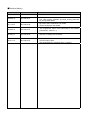
MITSUBISHI
Mitsubishi Industrial Robot
CR750-D/CR751-D series and CRnD-700 series
INSTRUCTION MANUAL
CC-Link Interface
BFP-A8701-E
Safety Precautions
Always read the following precautions and the separate "Safety
Manual" before starting use of the robot to learn the required
measures to be taken.
CAUTION All teaching work must be carried out by an operator who has received special
training. (This also applies to maintenance work with the power source turned ON.)
→Enforcement of safety training
CAUTION For teaching work, prepare a work plan related to the methods and procedures of
operating the robot, and to the measures to be taken when an error occurs or when
restarting. Carry out work following this plan. (This also applies to maintenance
work with the power source turned ON.)
→Preparation of work plan
WARNING Prepare a device that allows operation to be stopped immediately during teaching
work. (This also applies to maintenance work with the power source turned ON.)
→Setting of emergency stop switch
CAUTION During teaching work, place a sign indicating that teaching work is in progress on
the start switch, etc. (This also applies to maintenance work with the power source
turned ON.)
→Indication of teaching work in progress
CAUTION Provide a fence or enclosure during operation to prevent contact of the operator
and robot.
→Installation of safety fence
CAUTION Establish a set signaling method to the related operators for starting work, and
follow this method.
→Signaling of operation start
CAUTION As a principle turn the power OFF during maintenance work. Place a sign indicating
that maintenance work is in progress on the start switch, etc.
→Indication of maintenance work in progress
CAUTION Before starting work, inspect the robot, emergency stop switch and other related
devices, etc., and confirm that there are no errors.
→Inspection before starting work
The points of the precautions given in the separate "Safety Manual" are given below. Refer to the actual
"Safety Manual" for details.
CAUTION
CAUTION
CAUTION
CAUTION
CAUTION
Use the robot within the environment given in the specifications. Failure to do
so could lead to a drop or reliability or faults. (Temperature, humidity,
atmosphere, noise environment, etc.)
Transport the robot with the designated transportation posture.
Transportingthe robot in a non-designated posture could lead to personal
injuries or faultsfrom dropping.
Always use the robot installed on a secure table. Use in an instable
posturecould lead to positional deviation and vibration.
Wire the cable as far away from noise sources as possible. If placed near
anoise source, positional deviation or malfunction could occur.
Do not apply excessive force on the connector or excessively bend the
cable.Failure to observe this could lead to contact defects or wire breakage.
CAUTION
Make sure that the workpiece weight, including the hand, does not exceed
therated load or tolerable torque. Exceeding these values could lead to
alarms orfaults.
WARNING
Securely install the hand and tool, and securely grasp the workpiece. Failure
toobserve this could lead to personal injuries or damage if the object comes
off or flies off during operation.
WARNING
CAUTION
WARNING
CAUTION
Securely ground the robot and controller. Failure to observe this could lead
tomalfunctioning by noise or to electric shock accidents.
Indicate the operation state during robot operation. Failure to indicate the
statecould lead to operators approaching the robot or to incorrect operation.
When carrying out teaching work in the robot's movement range,
alwayssecure the priority right for the robot control. Failure to observe this
could leadto personal injuries or damage if the robot is started with external
commands.
Keep the jog speed as low as possible, and always watch the robot. Failure
todo so could lead to interference with the workpiece or peripheral devices.
CAUTION
After editing the program, always confirm the operation with step
operationbefore starting automatic operation. Failure to do so could lead to
interferencewith peripheral devices because of programming mistakes, etc.
CAUTION
Make sure that if the safety fence entrance door is opened during
automaticoperation, the door is locked or that the robot will automatically stop.
Failure todo so could lead to personal injuries.
CAUTION
Never carry out modifications based on personal judgments,non-designated
maintenance parts. Failure to observe this could lead to faults or failures.
WARNING
When the robot arm has to be moved by hand from an external area, do
notplace hands or fingers in the openings. Failure to observe this could lead
tohands or fingers catching depending on the posture.
CAUTION
Do not stop the robot or apply emergency stop by turning the robot
controller'smain power OFF.If the robot controller main power is turned OFF
during automatic operation,the robot accuracy could be adversely affected.
■Revision History
Print date
Instruction manual No.
Revision content
2008-08-08
BFP-A8701
・ First print
2009-06-15
BFP-A8701-A
・ (Notes) were added in Introduction.
・ The robot system variables (M_In8,M_In16,M_Out8 and
M_Out16) were added.
2011-12-27
BFP-A8701-B
・ Dip switch SW1 explanation was added.
・ CR751-D/CR750-D was added.
2012-03-13
BFP-A8701-C
・ The supplement about CR751-D/CR750-D was added.
(Introduction, Table 3.1 1)
2012-04-11
BFP-A8701-D
・ The error in writing was corrected.
2012-11-27
BFP-A8701-E
・ Notes about transmission delay time were added to the
communication cable.
・ The signal table was corrected. (Error in writing)
Introduction
Thank you very much for purchasing this product for Mitsubishi Electric Corporation's SD
series industrial robots. CC-Link (Control & Communication Link) interface is an add-on
option that is used in combination with CRnD-700 series controllers to add CC-Link field
network functionality to robot controllers. Please make sure to read this document
thoroughly and understand its information before start using the CC-Link interface.
Notes) In the software version P7th edition or later the updating cycle of the CC-Link
interface was accelerated. (the CR750-D/CR751-D controller is also included.)
Although it changes with the structure of the user program, the standard of
improvement in the speed is about one to 5 times. Therefore, in the existing robot
system or the robot system constructed by the same specification as existing, the
processing timing of the I/O signal will differ .
If the interlock of the I/O signal is not taken, the gap occurs to the timing of the signal
and it may be impossible for the robot system to operate normally. The accelerated
updating cycle can be returned to the origin by setting up "0" to the parameter:
CCREFCYC. This is effective if the timing of the I/O signal has a bad influence on
operation of the robot system.
Refer to " Table 3.2 3 List of Robot Parameters Used in CC-Link " for the details of the
parameter.
・ No part of this document may be reproduced without express permission of Mitsubishi
Electric Corporation.
・ Please note that the information in this manual is subject to change without notice in
the future.
・ Although this manual has been prepared to contain accurate information, please
contact us if you find any errors or have questions.
・ The product names used in this manual are trademarks or registered trademarks of
respective owners.
Copyright© 2008-2012 MITSUBISHI ELECTRIC CORPORATION ALL RIGHTS RESERVED
CONTENTS
1. BEFORE USE ......................................................................................................................................................................................1
1.1.HOW TO USE THE INSTRUCTION MANUAL ...............................................................................................1
1.2.GENERAL NAME AND ABBREVIATED NAME ...............................................................................................2
2. FLOW OF OPERATIONS..................................................................................................................................................................3
2.1.FLOWCHART...........................................................................................................................................3
3. FUNCTIONS AND SPECIFICATION OF THE CC-LINK INTERFACE......................................................................................4
3.1.WHAT IS CC-LINK?................................................................................................................................4
3.2.SPECIFICATION OF THE CC-LINK INTERFACE CARD ................................................................................5
3.3.HARDWARE OF THE CC-LINK INTERFACE CARD .................................................................................. 10
3.3.1. CARD OVERVIEW ....................................................................................................................................................................10
3.3.2. DIP SWITCH............................................................................................................................................................................10
3.3.3. LED........................................................................................................................................................................................12
4. ITEMS TO BE CHECKED BEFORE USING THIS PRODUCT.................................................................................................13
4.1.CHECKING THE PRODUCT.................................................................................................................... 13
4.2.DEVICES TO BE FURNISHED BY THE CUSTOMER .................................................................................. 13
5. HARDWARE SETTINGS.................................................................................................................................................................15
5.1.SETTINGS OF THE CC-LINK MASTER STATION...................................................................................... 15
6. CONNECTIONS AND WIRING.......................................................................................................................................................16
6.1.MOUNTING THE CC-LINK INTERFACE CARD IN THE CONTROLLER ........................................................ 16
6.1.1. CR750-D/CR751-D CONTROLLER ......................................................................................................................................16
6.1.2. CR1D-700 CONTROLLER ......................................................................................................................................................17
6.1.3. CR2D-700 CONTROLLER ......................................................................................................................................................18
6.1.4. CR3D-700 CONTROLLER ......................................................................................................................................................19
6.2.CONNECTION BETWEEN CC-LINK INTERFACE CARD AND MASTER STATION ........................................ 20
6.2.1. CONNECTION OF ONE-TOUCH CONNECTOR AND CABLE ONLY FOR CC-LINK........................................................................20
6.2.2. CONNECTION OF CC-LINK MASTER-STATION UNIT AND CABLE ONLY FOR CC-LINK .............................................................21
6.2.3. CONNECTION OF THE ONE-TOUCH CONNECTOR AND THE CC-LINK INTERFACE CARD .........................................................22
6.2.4. CC-LINK COMMUNICATION CABLE WIRING OF TWO OR MORE SET CONNECTION ..................................................................23
6.2.5. MEASURE AGAINST NOISE......................................................................................................................................................24
6.3.CHECKING CONNECTIONS ................................................................................................................... 26
7. BASIC COMMUNICATION PROCEDURE...................................................................................................................................27
7.1.SETTING THE PARAMETER OF CC-LINK MASTER STATION .................................................................... 28
7.2.SET THE PARAMETER OF THE ROBOT CONTROLLER.............................................................................. 30
7.2.1. SETUP OF PARAMETER ABOUT CC-LINK INTERFACE CARD ...................................................................................................30
7.2.2. SETUP OF SPECIAL I/O PARAMETER.......................................................................................................................................31
7.3.CREATING A MASTER STATION CC-LINK PROGRAM ............................................................................ 32
7.3.1. SIGNAL MAP OF MASTER STATION AND ROBOT ......................................................................................................................32
7.3.2. INSTALLATION OF SAMPLE RUDDER PROGRAM ......................................................................................................................32
7.3.3. FLOW CHART OF SAMPLE RUDDER PROGRAM .......................................................................................................................33
7.4.CREATE THE ROBOT PROGRAM NO. 1................................................................................................... 34
7.5.START THE ROBOT PROGRAM NO. 1 FROM THE MASTER STATION ........................................................ 34
7.6.EXAMPLE OF CHANGE OF SYSTEM CONFIGURATION ............................................................................. 35
7.6.1. ADD THE 2ND ROBOT CONTROLLER.......................................................................................................................................35
7.6.2. ADD THE ROBOT CONTROLLER TO THE SYSTEM WHICH FOUR SLAVE STATIONS ARE CONNECTED.......................................37
8. TROUBLESHOOTING .....................................................................................................................................................................39
8.1.LIST OF ERRORS ................................................................................................................................. 39
8.2.AN E7730 ERROR HAS OCCURRED AND CC-LINK DOES NOT ESTABLISH A LINK................................. 39
8.3.WHEN 7760 ERRORS (ABNORMALITIES IN CC-LINK INITIALIZATION) OCCUR ........................................... 40
9. APPENDIX..........................................................................................................................................................................................41
9.1.SAMPLE LADDER PROGRAM ................................................................................................................ 41
1. Before use
This chapter describes items to be checked and precautions to be taken before start using the CC-Link
interface.
1.1. How to Use the Instruction Manual
This manual is organized as follows and describes functions that have been added to or changed in the
CC-Link interface. For information about the functions provided for standard robot controllers and how to
operate them, refer to the instruction manual that comes with the robot controller you purchased.
Table 1.1-1 Contents of the Instruction Manual
Chapter
Title
Description
1
Before Using the CC-Link
Chapter 1 describes how to use this manual (CC-Link Interface
Interface
Instruction Manual). Please read this manual thoroughly before
actually starting to use the CC-Link interface.
2
Flow of Operations
Chapter 2 describes the operations required to configure a
CC-Link system. Make sure to perform all of the required
operations.
3
Functions and Specification
of the CC-Link Interface
Chapter 3 describes the functions and specification of the robot
CC-Link interface.
4
Items to Be Checked Before
Using This Product
Chapter 4 provides a list of items that come with the CC-Link
interface and the devices that need to be furnished by the
customer. Please verify that the CC-Link interface package you
purchased comes with the standard accessories and is
compatible with your system's robot controller version.
Chapter 5 describes how to perform hardware settings for
communication between the CC-Link interface and the master
station.
5
Hardware Settings
6
Connections and Wiring
Chapter 6 describes how to connect the CC-Link interface and
the master station using cables.
7
Basic Communication
Procedure
Chapter 7 describes a series of operations using the newly
installed CC-Link interface, configured and connected as
described in Chapters 4 to 6, from creating a master station's
CC-Link program to starting robot program No. 1. Learn how to
perform the basic operations following the instructions given for
each step as reference.
8
Troubleshooting
Chapter 8 describes how to resolve problems that may occur
when using the CC-Link interface, such as malfunctions and
errors. Please refer to this chapter as needed.
9
Appendix
Chapter 9 describes a sample ladder program that can be
entered when using the CC-Link interface as well as how to
monitor data with the RT ToolBox2 (personal computer support
software). Please refer to this chapter as needed.
1
1.2. General name and abbreviated name
Table 1.2-1 General name and abbreviated name
General / abbreviated name
Cyclic transmission
Transient transmission
Master station
Standby master station
Local station
Remote I/O station
Remote device station
Intelligent device station
Remote I/O net mode
Remote net mode
SB
(link special relay)
SW
(link special register)
RX
(remote input)
RY
(remote output)
RWw
(remote register for the writing)
RWr
(remote register for reading)
Details
Remote input and output, a transmission means to
communicate the details of the remote register periodically
A transmission method to specify the partner to any timing
and to communicate by 1:1
The station which controls the data link system
The one station is required for the one system.
The station for backup which succeeds data link control when
the master disconnected data link faulty by the abnormalities,
such as sequencer CPU and the power supply
The station which has sequencer CPU and can communicate
with the master station and other local stations
The station only treating the information on the bit unit
The station treating the information on the bit unit, and the
information on the word unit
The station treating the information on the bit unit, and the
information on the word unit, and also the transient
transmission
Special mode which transmits and receives the data at the
remote I/O station and the high speed
The mode which can communicate with all the stations for
CC-Link
Information on the bit unit which shows the operating state and
data link state of the unit of the master station and the local
station
Information on the 16-bit unit which shows the operating state
and data link state of the unit of the master station and the
local station
Information inputted by bit unit into the master station from the
slave station
Information outputted by bit unit into the master station from
the slave station
Information outputted to the remote device station, the local
station, and the intelligent device station from the master
station by 16 bits unit
Information inputted to the remote device station, the local
station, and the intelligent device station from the master
station by 16 bits unit
2
2. Flow of Operations
The flowchart below shows the flow of operations necessary for configuring a CC-Link interface system.
Use it as a reference to perform the required operations in the correct order.
2.1. Flowchart
1 Determining Specification for CC-Link Control........................See Chapter 3 of this manual.
Once you understand the CC-Link specification, specify the interfaces required for signals to be
communicated within your system via CC-Link communication (e.g., assignment of dedicated I/O signals,
specification of general-purpose I/O signals).
2 Checking Products .................................................................. See Chapter 4 of this manual.
Check the product you have purchased and prepare other products as needed.
3 Hardware Settings and Wiring................................................. See Chapters 5 and 6 of this manual.
Set up the CC-Link interface card as well as the master station. After you have made the settings, install
the CC-Link interface card in the robot controller, and then wire the installed CC-Link interface card and the
master station.
4 Creating a Ladder Program for the Master Station ................. See Section 7.1 of this manual.
Create a ladder program for the master station so that it can be linked to the robot controller.* If the robot
controller is started without running a ladder program stored in the master station, an E7730 error (CC-Link
local station link error) occurs.
5 Setting Robot Controller Parameters....................................... See Section 7.2 of this manual.
Set dedicated I/O signals for communication between the master station and the robot controller. With this
setting, it becomes possible to control the robot controller from the master station.
6 Creating Robot Programs........................................................ See Section 7.3 of this manual.
Create robot programs according to the specification determined in Operation 1 above.
7 Performing CC-Link Control .................................................... See Section 7.4 of this manual.
Run the ladder program stored in the master station and perform control via the CC-Link communication.
8 Completion of Operations
3
3. Functions and Specification of the CC-Link Interface
3.1. What Is CC-Link?
PC
Inverter
GOT
Remote station
Peripheral
equipment
Remote device
CR75n-D/CRnD-700
controller
CRnD-700 controller
M ELSEC
QJ71E71-100
Q173NCCPU
POWER
RUN
INIT .
OPEN
SD
QXxxxx
QJ71E71-100
ERR.
COM.ERR.
100M RD
RUN
INIT.
OPEN
SD
QXxxxx
QXxxxx
ERR.
COM.ERR.
100M RD
PULL
FRONT
BAT
MPG
ACFAIL
RIO
MITSUBISHI
Option slot 1, 2 or 3
(Up to the one board)
Master
Masterstation
station unit
it
CC-Link interface board
(TZ576)
Note) An example of CR3D-700 controller.
Table 3.1-1 CC-Link Network Configuration Diagram
CC-Link is a field network (*1) that provides not only simple bit control but also additional functions such as
data control and message transmission/reception in order to accommodate the continuous advances in the
functionality of various control devices. CC-Link supports cyclic transmission of not only bit data but also word
data, facilitating communication with intelligent devices such as inverters, indicators and other I/O devices.
Distributed systems can be built easily by setting up an n:n cyclic transmission network to which a master
station and several local stations are connected. The best communication distance and speed can be selected
in a flexible manner according to your system requirements. The optimal system can be built by selecting the
most suited devices from the rich product lines of the CC-Link partner manufacturers.
This CC-Link interface card operates as an intelligent device station.
(*1) Please visit the Web site of the CC-Link Partner Association (http://www.cc-link.org/) for more information
about CC-Link.
3. Functions and Specification of the CC-Link Interface
4
3.2. Specification of the CC-Link Interface Card
Table 3.2-1 General Specification (Specification of HR575 Card)
Item
Specification
Communication function
Both bit data and word data can be
transmitted.
Type name of CC-Link interface card
TZ576
Remarks
Word data is used in the
registers.
Mountable option slot
1, 2, or 3
Use one of the slots
Number of mountable cards
1 card
It is not allowed to insert
multiple cards.
The extended cyclic setup
is possible
Transient transmission is
not supported.
Master station
functionality is not
available.
Set using the dip switches
on the card.
If two or more station
occupancy, it becomes
the continuation station
number.
Ver.2
Version corresponding to CC-Link
Station type
Intelligent device station
Supported station functionality
Local station
Station number
Can be set between station numbers
1 and 64
10 M, 5 M, 2.5 M, 625 k, 156 kbps
Baud rate
Number of occupied stations
Can be set to occupy 1, 2, 3, or 4
stations.
Extended cyclic setup
Can be set to 1, 2, 4, or 8 multiple.
Number of I/O
points
Remote input (RX)
896 max.
Remote output (RY)
896 max.
Remote register (RWr)
128 max.
Remote register (RWw)
128 max.
Transient transmission
Not supported
Parameter
The last two points cannot
be used.
One register consists of
16 bits.
Initial value
Special
I/O
STOP2
-1 , -1
DIODATA
-1 , -1
Common
CCERR
0
E7730
0
CCINFO
1,1,1
CCSPD
4
CCCLR
0
CCFIX
1
CCFIL
1000, 200
1
CCREFCYC
MELFA-BASIC
I/O signal access
M_In/ M_Inb/ M_In8 / M_Inw/ M_In16
M_Out/ M_Outb/ M_Out8/ M_Outw/ M_Out16
Register access
M_DIn, M_DOut
5
Refer to "Table 3.2 3
List of Robot
Parameters Used in
CC-Link" for details.
Table 3.2-2 I/O point per robot controller
Item
Occupancy
Signal
station
I/O signal
One station
Register
I/O signal
Two-station
Register
I/O signal
Three-station
Register
I/O signal
Four-station
Register
1 fold setup
Extended cyclic setup
2 fold setup
3 fold setup
4 fold setup
32
4
64
8
96
12
128
16
32
8
96
16
160
24
224
32
128
32
384
64
640
96
896
128
point
point
point
point
point
point
point
point
point
point
point
point
point
point
point
point
64
16
192
32
320
48
448
64
point
point
point
point
point
point
point
point
point
point
point
point
point
point
point
point
Table 3.2-3 List of Robot Parameters Used in CC-Link
Item
Function
Set the input number for stopping the robot program from the CC-Link master station to the
1st element.
STOP2
Set the output number which indicates that the robot program is stopping to the 2nd
element
Set the register input number when specifying the program number and OVRD to the 1st
element.
DIODATA
Set the program number, the error number, and the register output number that outputs the
number of the lines to the 2nd element.
If the CC-Link master station is not turned on or if doing the operations of the robot stand
alone before setting the parameter of the master station, the 7750 errors (the cc-Link
master-station parameter is unusual) or the 7730 errors (the cc-Link link is unusual) occur
CCERR
This parameter enables reset of error temporarily.
0: If the link is abnormal, always error
1: Reset is possible
* This parameter is the power supply reset needlessness of the robot controller.
This parameter enables reset of 7730 errors (the cc-Link link is unusual) temporarily.
0: If the link is abnormal, always error
E7730
1: Reset is possible
* This parameter is the power supply reset needlessness of the robot controller.
There are the three elements of this parameter and they set up the number of CC-Link, the
number of occupancy station, and the extended cyclic setup separately.
CCINFO
(Element 1 = Number
:1 to 64 stations)
(Element 2 = Number of occupancy station :1 to 4 stations)
(Element 3 = Extended cyclic setup :Set up 1, 2, 4, or the 8 fold.)
Set up the transmission speed of CC-Link.
CCSPD
(0: 156k / 1: 625k / 2: 2.5M / 3: 5M / 4: 10M)
When the abnormalities in the data link occur, specify whether the input signal is held or it
clears.
CCCLR
1: Hold
0: Clear
Set up whether the CC-Link signal number is fixed or not.
0: Use the signal number of the specified station number.
(Ex.) Set the station number as 3.
CCFIX
I/O signal number = from No. 6064 / Register number = from No. 6008
1: Use the signal number from No. 6000 regardless of the station number.
(Ex.) Set the station number as 3.
I/O signal number = from No. 6000 / Register number = from No. 6000.
Set up the master-station parameter abnormal detection filter and the data link abnormal
detection filter. The unit is ms.
CCFIL
If only the time specified by each abnormal condition is being continued, the 7750 errors
and the 7730 errors occur.
6
Item
CCREFCYC
Function
Change the update cycle of the CC-Link interface.
High-speed mode/Compatibility mode = 1/0
In the software version P7th edition or later the updating cycle of the CC-Link interface was
accelerated.
If "0" is set up, it will operate in same updating cycle as before. This is available if the
compatibility with the robot system constructed by the software version prior to P7 edition is
necessary.
The updating cycle of the input-output signal was sped up in the following software versions:
CRnD-700 series controller: Ver.P7 or later
CR750-D/CR751-D series controller: S3 or later
Table 3.2-4 List of Robot Program Commands Used in CC-Link
Item
Function
M_In
Reads 1-bit data of the specified input signal
M_Out
Writes 1-bit data to the specified output signal
M_Inb/ M_In8
Reads 8-bit data from the specified input signal
M_Outb/ M_Out8
Writes 8-bit data to the specified output signal
M_Inw/ M_In16
Reads 16-bit data from the specified input signal
M_Outw/ M_Out16
Writes 16-bit data to the specified output
M_Din
Reads data of the specified input register
M_DOut
Writes data to the specified output register
7
Table 3.2-5 Signal table
(1) In case of the parameter "CCFIX" is "1" in CC-Link Ver.2
Remote signal
Remote register
Station
number
Occupancy
station
Extended
cyclic setup
Input
Output
Input
Output
0(Master)
-
-
-
-
-
-
One
station
Tow station
1 to 64
Three
station
Four
station
1 fold
6000
to
6031
6000
to
6031
6000
to
6003
6000
to
6003
2 fold
6000
to
6063
6000
to
6063
6000
to
6007
6000
to
6007
4 fold
6000
to
6095
6000
to
6095
6000
to
6015
6000
to
6015
8 fold
6000
to
6127
6000
to
6127
6000
to
6031
6000
to
6031
1 fold
6000
to
6063
6000
to
6063
6000
to
6007
6000
to
6007
2 fold
6000
to
6095
6000
to
6095
6000
to
6015
6000
to
6015
4 fold
6000
to
6191
6000
to
6191
6000
to
6031
6000
to
6031
8 fold
6000
to
6383
6000
to
6383
6000
to
6063
6000
to
6063
1 fold
6000
to
6095
6000
to
6095
6000
to
6011
6000
to
6011
2 fold
6000
to
6159
6000
to
6159
6000
to
6023
6000
to
6023
4 fold
6000
to
6319
6000
to
6319
6000
to
6047
6000
to
6047
8 fold
6000
to
6639
6000
to
6639
6000
to
6095
6000
to
6095
1 fold
6000
to
6127
6000
to
6127
6000
to
6015
6000
to
6015
2 fold
6000
to
6223
6000
to
6223
6000
to
6031
6000
to
6031
4 fold
6000
to
6447
6000
to
6447
6000
to
6063
6000
to
6063
8 fold
6000
to
6895
6000
to
6895
6000
to
6127
6000
to
6127
*The last two points cannot be used.
(2) In case of the parameter "CCFIX" is "1" in CC-Link Ver.1
Remote signal
Remote register
Station
number
Occupancy
station
Extended
cyclic setup
Input
Output
0(Master)
One
station
Tow station
Three
station
Four
station
-
-
-
1 to 64
1 fold only
-
-
6000
to
6031
6000
to
6031
6000
to
6003
6000
to
6003
6000
to
6063
6000
to
6063
6000
to
6007
6000
to
6007
6000
to
6095
6000
to
6095
6000
to
6011
6000
to
6011
6000
to
6127
6000
to
6127
6000
to
6015
6000
to
6015
*The last two points cannot be used.
8
Table 3.2-6 Table of CC-Link Signals
(The numbers in the table indicate the numbers of the I/O signals handled by the robot controller.)
Remote signal
Remote register
Station number
Input
Output
Input
Output
0 (master)
1
6000 to 6031
6000 to 6031
6000 to 6003
6000 to 6003
2
6032 to 6063
6032 to 6063
6004 to 6007
6004 to 6007
3
6064 to 6095
6064 to 6095
6008 to 6011
6008 to 6011
4
6096 to 6127
6096 to 6127
6012 to 6015
6012 to 6015
5
6128 to 6159
6128 to 6159
6016 to 6019
6016 to 6019
6
6160 to 6191
6160 to 6191
6020 to 6023
6020 to 6023
7
6192 to 6223
6192 to 6223
6024 to 6027
6024 to 6027
8
6224 to 6255
6224 to 6255
6028 to 6031
6028 to 6031
9
6256 to 6287
6256 to 6287
6032 to 6035
6032 to 6035
10
6288 to 6319
6288 to 6319
6036 to 6039
6036 to 6039
11
6320 to 6351
6320 to 6351
6040 to 6043
6040 to 6043
12
6352 to 6383
6352 to 6383
6044 to 6047
6044 to 6047
13
6384 to 6415
6384 to 6415
6048 to 6051
6048 to 6051
14
6416 to 6447
6416 to 6447
6052 to 6055
6052 to 6055
15
6448 to 6479
6448 to 6479
6056 to 6059
6056 to 6059
16
6480 to 6511
6480 to 6511
6060 to 6063
6060 to 6063
17
6512 to 6543
6512 to 6543
6064 to 6067
6064 to 6067
18
6544 to 6575
6544 to 6575
6068 to 6071
6068 to 6071
19
6576 to 6607
6576 to 6607
6072 to 6075
6072 to 6075
20
6608 to 6639
6608 to 6639
6076 to 6079
6076 to 6079
:
:
:
:
:
63
64
7984 to 8015
8016 to 8047
7984 to 8015
8016 to 8047
6248 to 6251
6252 to 6255
6248 to 6251
6252 to 6255
CAUTION In case of the inside signal point of the robot is exceeded, be careful of the point
decreasing.
If the parameter "CCFIX" is set as "0" in CC-Link Ver.2, access from the signal number
corresponding to the station number. For this reason, the following cares are required if the
station number becomes large.
In the 8 fold setup by four-station occupancy of the robot, the signal point number of I/O
signal is 896, and for registers is 128 words.
However, when the number is set as the 64 stations, the permissible signal points in the
robot are the remaining 32 points (8016-8047) and the 4 words (6252-6255).
For this reason, since the set-up point cannot be used, be careful.
9
3.3. Hardware of the CC-Link Interface Card
This section describes the settings that are performed by using the rotary switches and DIP switches on the
CC-Link interface card.
3.3.1. Card overview
(1) General Layout of the Card
DIP switch(SW1/SW2/SW3)
LED
CC-Link cable
connection connector
Figure 3.3-1 General Layout of the Card
3.3.2. DIP switch
There are the three DIP switches (SW1 / SW2 / SW3) on the CC-Link interface card (TZ576).
The item which can be set up with each DIP switch is shown in the following.
Table 3.3-1 Function of DIP switch (SW1)
Switch
OFF
1
SW1
2
3
4
Factory
setting
ON
ON
ON (fixation)
Ver.1 mode
Ver.2 mode
ON
OFF (fixation)
OFF (fixation)
OFF
OFF
10
Description
Specify the version of CC-Link.
In case of the Ver.2 mode, the
extended cyclic setup is possible.
Please change neither SW2 nor SW3 like an initial value (turn off all).
The initial state of each switch is shown in the following.
Figure 3.3-2 State of initialization of dip switch (SW2)
Figure 3.3-3 State of initialization of dip switch (SW3)
11
3.3.3. LED
There is eight LED on the CC-Link interface card (TZ576), and the operating state of the interface
card can be confirmed by each lighting / blink / lights-out.
LRUN
RUN
RD
SD
LERR
ERR
RST
WDT
Figure 3.3-4 Layout of LEDs
Table 3.3-2 Description of LED
LED name
LRUN
RD
LERR
RST
RUN
SD
ERR
WDT
Conditions for turning on
Lighting
Lighting
Lighting
Blink
Lighting
Lighting
Lighting
Lighting
Lighting
Blink
Lighting
During data link
During data receiving
Self-station communication error
The DIP switch is changed during turning on the power supply
During reset processing execution of the interface card
Operation is normally
Watch dog timer error
During data sending
Turn on at the following error occurrence. The communication of all
station are abnormal
The setup of the DIP switch is abnormal
The master station overlaps on the same line.
The details of the parameter are abnormal.
The data link monitor timer operated
The cable is disconnected
The noise is effect to the transmission way
The communication abnormal station exists.
Watch dog timer error
LRUN
RD
LERR
RST
RUN
SD
ERR
WDT
Figure 3.3-5 The LED lighting state at normal
12
4. Items to Be Checked Before Using This Product
4.1. Checking the Product
The product you purchased consists of the following items as standard. Please verify that the package
contains all the items.
Table 4.1-1 List of the Standard Items in the Package
No. Note1)
Name
Type
Quantity
Note2)
BFP-A8701
1
Instruction
Manual
(this
manual)
①
CC-Link interface card
TZ576
1
②
Ferrite
core
E04SR301334
2
③
On-line connector for communication
A6CON-LJ5P
1
④
Terminator
A6CON-TR11
1
⑤
One-touch
connector
plug
for
A6CON-L5P
2
⑥
communication
Cable clamp
AL5
2
⑦
Cable clamp
AL4
2
⑧
Note1) The number of the table is equivalent to the number of following figure.
Note2) This manual is included in instruction-manual CD-ROM attached to the product.
①
②
③
⑤
⑥
⑦
④
⑧
[AL4]
D=6.4mm
[AL5]
D=9.6mm
Figure 4.1-1 Items Contained in the Package
4.2. Devices to Be Furnished by the Customer
When using Mitsubishi Electric CC-Link interface card, the devices listed in Table 4.2 below must be
furnished by the customer.
Table 4.2-1 Equipment prepared of the customer
Device to be furnished
Condition
Master station
The master station corresponding to the intelligent device station
Communication cable
The cable only for CC-Link
*1) Performance of the CC-Link system cannot be guaranteed except the
cable only for CC-Link.
The maximum cable total extension and the cable length for the station
have restriction.
Note) If extended cyclic setting is set up more than double, transmission delay time
will become long. Refer to the instruction manual of CC-Link for details.
*1) For details, refer to "the cc-Link association (http://www.cc-link.org/)."
13
14
5. Hardware Settings
5.1. Settings of the CC-Link Master Station
The details of the setting of the master station are shown in the following. For details, please refer to "the
cc-Link system master local unit
user's manual (volume on details)."
LED
Rotary switch (station number)
Rotary switch (mode)
Terminal
Figure 5.1-1 The outline of the CC-Link master-station unit (Q series)
As shown in Table 5-1, set up the rotary switch of the CC-Link master-station unit.
For details, please refer to "the cc-Link system master local unit user's manual (volume on details)."
Table 5.1-1 The setup of the CC-Link master-station unit (Q series)
Item
Details of setting
At shipping
Example
of setting
0
0
X10:Set the ten digit of a station number
0
X1:Set the ten digit of a station number
0
Mode
Set the mode
0:Transmission speed 156kbps
Rotary
switch
1:Transmission speed 625kbps
0
4
2:Transmission speed 2.5Mbps
3:Transmission speed 5Mbps
4:Transmission speed 10Mbps
Notice) When the mode of the master station is changed, change the parameter "CCSPD" of
the robot controller.
②Station
number
15
6. Connections and Wiring
6.1. Mounting the CC-Link Interface Card in the Controller
For more information about how to mount the CC-Link interface card, refer to the "Installing Optional
Devices" in "Controller Setup and Basic Operations to Maintenance" in the instruction manual of the
corresponding controller. Install only one CC-Link interface card in either of the option slots 1-3 of the robot
controller. In case of the two or more sheets are installed, the 7720 errors (equipped with two or more
cc-Link cards) occur.
6.1.1. CR750-D/CR751-D controller
Remove one interface cover of the option slots two in the robot controller rear, and mount the CC-Link
interface card there. Please use the handle of the interface card at mounting of the interface card.
<CR750-D controller rear>
SLOT1
<CR751-D controller front>
Interface
cover
インタフェースカバー
Interface
cover
インタフェースカバー
取外しレバー
removal
lever
SLOT2
Connector
接続コネクタ
Interface
card
インタフェースカード
Handle
取っ手
取外しレバー
Removal
lever (Other side)
(下側)
Figure 6.1-1 Mounting of the CC-Link interface card (CR750-D/CR751-D controller)
16
6.1.2. CR1D-700 controller
Remove one interface cover of the option slots 1 in the robot controller rear, and mount the CC-Link
interface card there. Please use the handle of the interface card at mounting of the interface card.
Controller rear
SLOT1
Interface cover
removal lever
Interface cover
CConnector
o n n e c to r
Interface
In te rfa ccard
e c a rd
H
a n d le
Handle
Removal
R
e m o v alever
l le v e r
Figure 6.1-2 Mounting of the CC-Link interface card (CR1D controller)
17
6.1.3. CR2D-700 controller
Remove one interface cover of the option slots 1-3 in the robot controller rear, and mount the CC-Link
interface card there. Please use the handle of the interface card at mounting of the interface card.
Interface cover removal
インタフェースカバー
lever
取外しレバー
Interface
cover
インタフェースカバー
Connection connector
接続コネクタ
Interface card
インタフェースカード
Lever
取っ手
取外しレバー
Removal
lever
Figure 6.1-3 Mounting of the CC-Link interface card (CR2D controller)
18
6.1.4. CR3D-700 controller
Open the door of the robot controller.
The R700CPU unit is installed in the right end. Remove one interface cover of the option slots 1-3 in
the CPU unit, and mount the CC-Link interface card there.
Please use the handle of the interface card at mounting of the interface card.
R700CPU unit
Interface card
Lever
Interface cover
Interface cover
removal lever
Removal
lever
Connection connector
Figure 6.1-4 Mounting of the CC-Link interface card (CR3D controller)
19
R700CPU unit
6.2. Connection Between CC-Link Interface card and Master Station
Explain the connection method for the CC-Link interface card mounted in the robot controller, and
the CC-Link master-station unit.
6.2.1. Connection of one-touch connector and cable only for CC-Link
Connection method of the cable for CC-Link only prepared by the customer and one-touch connector
attached to this product is shown in the following.
(1) Peel covering of the cable only for CC-Link (It is not necessary to peel covering of the internal
cable)
・・・・・
(2) Insert the electric wire of the cable for CC-Link to the one-touch connector.
Signal name
DA(Blue)
DB(white)
DG(Yellow)
NC
SLD
(3) Close the connector with pliers
(4) Complete
20
6.2.2. Connection of CC-Link master-station unit and cable only for CC-Link
The connection method of the CC-Link master-station unit prepared by the customer and the CC-Link
cable is shown in the following.
(1) Stick another side of the CC-Link cable by pressure.
・・・・・
(2) Connect the shield line to the SLD terminal in the terminal of the master-station unit. Refer to the
lower right figure
(3) Connect the electric wire to DA, DB and DG in the terminal of the master-station unit.
(4) Connect the terminal to the master-station unit.
Point
Installation of the terminator is required for the
both ends of the CC-Link network.
Connect the terminator to the both ends of the
equipment connected to the CC-Link network. Be careful
that the resistance differs with the kind of cable.
21
6.2.3. Connection of the one-touch connector and the CC-Link interface card
The connection method of the one-touch connector (cable only for cc-Link) and the CC-Link
interface card is shown in the following.
(1) Connect the one-touch connector to the on-line connector for communication. Also connect the
terminator if needed.
(2) Connect the on-line connector for communication (connected communication cable) to the
CC-Link interface card.
By the operations so far, it becomes the following system configurations.
An example of CR3D-700 controller
M EL S EC
QJ71E71-100
Q173NCCPU
POWER
RUN
INIT .
OPEN
SD
QXxxxx
QJ71E71-100
ERR.
C OM.ERR.
100M RD
RUN
INIT.
OPEN
SD
QXxxxx
QXxxxx
ERR.
COM.ERR.
100M RD
PULL
MITSUBISHI
FRO NT
BAT
MPG
ACF AIL
RIO
Master-station unit
Master-station
unit
CC-Link interface card
Figure 6.2-1 The 1 to 1 connection structure figure of the robot controller and the CC-Link
master station (CR3D-700 controller)
22
6.2.4. CC-Link communication cable wiring of two or more set connection
If two or more slave stations connected, prepare one more CC-Link cable connected to the
one-touch connector, and connect as shown in the following
Figure 6.2-2 The example of one-touch connector connection for two or more station connection
DA
DB
DG
SLD
Terminator
Terminat
Shield
CC-Link master-station side
Shield
CC-Link
Interface card
DA
DB
DG
SLD
I/O
リモート
Remote
I/O station
Figure 6.2-3 The example of CC-Link cable connection for two or more station connection
23
6.2.5. Measure against noise
Because of the measure against the noise, please peel the sheath of the CC-Link cable, and the
ground clamp of the metal braid section at the case, and mount the ferrite core (recommendation
article: E04SR301334 * SEIWA ELECTRIC MFG.) on less than 30cm from the clamp position.
The connection method by controller is shown in the following.
(1) CR750-D/CR751-D controller
<CR750-D controller rear>
Cable
ground clamp
ケーブルアースクランプ位
置
position
*1 プ付属品)
(アースクラン
(Ground clamp
attachments)
フェライトコア
Ferrite
core
(付属品)
(attachments)
CC-Link cable
CC-Linkケーブル
(お客様準備)
(Customer
preparation)
<CR751-D controller front >
Cable ground clamp
position
*1
ケーブルアースク
ランプ位置
(Ground
clamp
(アースクランプ付属
品)
attachments)
Ferrite
core
フェライトコア
(付属品)
(attachments)
CC-Link cable
CC-Linkケーブル
(お客様準備)
(Customer
preparation)
Figure 6.2-4 Connection of the CC-Link cable (CR750-D/CR751-D controller)
(2) CR1D-700 controller
Rear cover
Cable ground clamp position *1
(Ground clamp attachments)
Less than 30cm
CC-Link cable
(Customer preparation)
Ferrite core
(attachments)
Figure 6.2-5 Connection of the CC-Link cable (CR1D-700 controller)
24
(3) CR2D-700 controller
Cable ground clamp position *1
(Ground clamp attachments)
Rear cover
Less than 30cm
Ferrite core
(attachments)
CC-Link cable
(Customer preparation)
Figure 6.2-6 Connection of the CC-Link cable (CR2D -700 controller)
(4) CR3D-700 controller
R700CPU unit
CC-Link cable
(Customer preparation)
Cable ground clamp position *1
(Ground clamp attachments)
Ferrite core
(attachments)
Less than 30cm
Figure 6.2-7 Connection of the CC-Link cable (CR3D -700 controller)
*1)
Cable ground clamp position
The cable peels the sheath and grounds
the metal braid section to the case.
Sheath
シース
Sheath
シース
20~30mm
金属製ブレード部
Metal
braid section
25
6.3. Checking Connections
Check the following connections again before using the CC-Link interface card.
Table 6.3-1 Checking Connections
No.
Check item
1
2
Is the CC-Link interface card securely installed in slot of the controller?
Are the CC-Link cables between the CC-Link interface card and the external
devices you provided connected properly?
3
Are the rotary switches and DIP switches on the card set correctly?
4
Is a terminal resistor installed?
5
Is the ferrite core attached?
26
Check
7. Basic Communication Procedure
This chapter describes the operations from creating a master station's CC-Link program to establishing a
communication by running the sample ladder program provided with this product, using a system configured
with one CC-Link interface card connected to one PLC master station module (one-to-one connection).
The sample ladder program provided starts up robot program No. 1.
* For information about communication via the personal computer CC-Link interface board, refer to the
instruction manual of the personal computer CC-Link interface board.
Setting the parameter of CC-Link master station............... See section 7.1 Setting the parameter of CC-Link
master station
↓
Setting the parameter of robot controller ........................... See section 7.2 Set the parameter of the robot
controller
↓
Creating a master station CC-Link program ...................... See section 7.3 Creating a Master Station CC-Link
Program
↓
Creating robot program No. 1 ............................................ See section 7.4 Create the robot program No. 1
↓
Running robot program No. 1 ............................................ See section 7.5 Start the robot program No. 1 from the
master station
27
7.1. Setting the parameter of CC-Link master station
Set it as the CC-Link master station that the robot's CC-Link interface card exists on the CC-Link
network. In case of Q series of the MELSEC sequencer, explain to the example the case that the
utility for setting the parameter for CC-Link communication is used.
In addition, please refer to "the cc-Link system master local unit
user's manual (volume on
details)" for the details of the parameter setup which uses GX Developer.
(1) Connect the MELSEC sequencer with the personal computer by the USB cable, the RS-232C
cable, etc.
(2) Start GX Developer
(3) Select [on-line]-[PC read-out] from the menu, select the kind of connected cable, and read the
parameter and the program on GX Developer.
(4) Select the [parameter] icon in the left frame of GX Developer, and double-click the [network
parameter].
(5) Click the [CC-Link] button on the displayed "network parameter selection" screen.
(6) Set up the following on the displayed "network parameter setting" screen.
Initial
No.
Item
Details
value
Head I/O No.
The CC-Link master station specifies the head I/O
number of the unit which shows the mounting
Blank
1
position on the base board of the MELSEC
sequencer.
Number of
Set up all the number of connection of the slave
64
station connected on the CC-Link network.
2 connection
(Range: 1-64)
Remote
Set up the device for refreshment of data
Blank
3
input/output
communications with slave station.
Blank
4 Remote register
5
Station
information
Set up the type of remote station and local station
which connected.
28
Button
Setting
example
0060
1
X1000
Y1000
W0
W1000
Refer to
the
following
page
(7) Click the "Station information" button and set up the slave station.
No.
Item
Station classification
1
Ver.1 remote I/O station
Ver.1 remote device
station
Ver.1 intelligent device
station
Ver.2 remote device
station
Ver.2 intelligent device
station
Extended cyclic setup
2
1 fold setup
2 fold setup
4 fold setup
8 fold setup
Number of occupancy
stations
3
One-station occupancy
Tow-station occupancy
Three-station occupancy
Four-station occupancy
Reservation / invalid
station specification
4
With no setup
Reservation station
Invalid station
Details
The robot's CC-Link interface card
specifies the "Ver.2 intelligent device
station."
In case of the 2nd switch (cc-Link
version) of DIP switch SW1 on the
CC-Link interface card is turned
"OFF", specify the "Ver.1 intelligent
device station."
Since the CC-Link version is "Ver.2"
in initial setting, the multiple setup is
possible.
By changing the multiple setup, it is
possible to increase the point of
remote I/O which can communicate,
and the register.
Specify the number of the stations
which the slave station occupies.
The a maximum of four stations can
be occupied.
In case of the slave station has
connected on the CC-Link network,
select the "No setup."
In the future, the "reservation station"
will be specified about the slave
station which is due to be connected
(extension).
And, the slave station which the error
does not detect at the time of error
occurrence specifies the "invalid
station."
Initial value
Ver.1 remote
I/O station
1 fold setup
Setting
example
Ver.2 intelligent
device station
1 fold setup
One-station
occupancy
One-station
occupancy
With no
setup
With no setup
(8) If all are set up, confirm that no error by click [error-checking] button.
(9) Click the [finishing of the setting] button, and click the [finishing of setting] button on the "network
parameter setting screen."
(10) Click [on-line]-[PC write-in] from the menu of GX Developer, and write the parameter in the
MELSEC sequencer.
In addition, please refer to "the parameter setup by GX Developer" of "the cc-Link system master local
unit user's manual (volume on details)" for the details about the setup.
29
7.2. Set the parameter of the robot controller
Explain the setting method of the special I/O parameter required to execute the sample rudder
program shown in appendix, and operate the CC-Link interface card.
Please refer to separate manual "Detailed description of the function and operation" for details of the
robot controller parameter.
7.2.1. Setup of parameter about CC-Link interface card
To operate the CC-Link interface card, set the parameter shown below. Make the station number, the
number of occupancy stations, the extended cyclic setup, etc. the same as the setup of the slave
station.
Table 7.2-1 Parameter for CC-Link interface cards
Parameter
Setting
Function
name
value
Set up the station number of CC-Link, the number of occupancy
stations, and the extended cyclic setup.
1,1,1
CCINFO
(Element 1 = station number :1 to 64)
(Element 2 = number of occupancy stations :1 to 4)
(Element 3 = extended cyclic setup :1, 2, 4, or 8)
Set the transmission speed of CC-Link.
4
CCSPD
(*1)
(0: 156k / 1: 625k / 2: 2.5M / 3: 5M / 4: 10M)
Set up whether the CC-Link signal number is fixed or not.
0: Use the signal number of the specified station number.
(Ex.) Set the station number as 3.
I/O signal number = from No. 6064 / Register number = from
1
No. 6008
CCFIX
(*2)
1: Use the signal number from No. 6000 regardless of the station
number.
(Ex.) Set the station number as 3.
I/O signal number = from No. 6000 / Register number = from
No. 6000.
(*1) It is the setting value assumed to have set the [MODE] setup (rotary switch) of the master-station
unit to "4."
(*2) In case of the system changed into this interface card, from the previous CC-Link interface card
(HR575), it becomes compatibility by setting it as "0."
30
7.2.2. Setup of special I/O parameter
To execute in the appendix sample rudder program, so the MELSEC sequencer control the robot
controller, set up the special I/O parameter as shown below. After the setup turn off the power supply
once of robot controller, because of to enable the parameter.
Table 7.2-2 Special I/O parameter
Parameter
Setting
Item
Name
name
value
Operation rights input
Input
6000
signal
IOENA
Operation rights output
Output
6000
signal
Remote mode output
Output
ATEXTMD
6001
Input
6002
Output
6002
Input
6003
Output
6003
Input
6004
Output
6004
Input
6005
Input
6006
Output
6006
Input
6007
Output
6007
Input
6008
Output
6008
Input
6009
Output
6009
Input
Register
Output
Register
6000
SRVON
SLOTINIT
PRGOUT
PRGSEL
START
ERRRESET
STOP2
(*1)
SRVOFF
DIODATA
(*2)
Servo ON input signal
In servo ON output
signal
Program reset
Program selection
enabled output
Program No. output
request
Program No. output
signal
Program selection input
signal
Start input
Operating output
Error reset input signal
Error occurring output
signal
Stop input
Pausing output
Servo OFF input signal
Servo ON disable
output signal
Numeric value input
Sets the validity of the operation rights for the
external signal control.
Outputs the operation rights valid state for the
external signal
This output indicates that the key switch on the
operation panel is set to AUTO (Ext.), which is a
remote operation mode.
This input turns ON the servo power supply for
the robot.
This output turns ON when the servo power
supply for the robot is ON.
This input cancels the paused status of the
program and brings the executing line to the top.
Executing a program reset makes it possible to
select a program.
Outputs that in the program selection enabled
state.
The program number for task slot 1 is output to
the numerical output (IODATA).
The "program number output in progress" status
is output to the numerical output.
Designates the setting value for the program No.
with numeric value input signals.
This input starts a program.
This output indicates that a program is being
executed.
Releases the error state.
Outputs that an error has occurred.
This input stops the program being executed.
This output indicates that the program is
paused.
This input turns OFF the servo power supply for
the robot.
This output indicates a status where the servo
power supply cannot be turned ON.
The specified numeric values are loaded.
The numeric values of the specified items are
output.
(*1) The Skip input No. 0 is being fixed to the remote input No. 0. Therefore use the parameter
"STOP2" for stop input signal of CC-Link
(*2) In CC-Link, it is possible to specify the program number and the OVRD value with the parameter
"DIODATA" (the register input, the register output).
In the rising edge of the signal assigned to the parameter "PRGSEL" or "OVRDSEL", the
numerical value of the input register is set as the "program number" and the "OVRD value."
However, in case of the parameter "IODATA" is set, be careful the higher priority is IODATA.
And, the "program number" and the "error number" are outputted to the specified output register
in the rising edge of the signal assigned to the parameter "PRGOUT", "ERROUT", etc.
In case of the parameter "IODATA" is set, it is outputted also to the specified signal number.
6000
Numeric value output
Details
31
7.3. Creating a Master Station CC-Link Program
This section describes the procedure for creating a program that allows the CC-Link master station module
to communicate using a one-to-one connection with the CC-Link interface card of the robot.
7.3.1. Signal map of master station and robot
With the specified station number or setting values of the parameter "CCFIX", the refreshment
device of the signal number and the master station used by the robot program changes. Here, the
signal map in the one station, the one-station occupancy, and the 1 fold setup which were set up in
Chapter 7.1 is shown in "Table 7.3-1.
Please refer to chapter 7.6 Example of change of system configuration for changing the station
number, the number of occupancy stations, the extended cyclic setup, etc.
Table 7.3-1 Signal allocation map of the master station and the robot (remote signal)
Master station
Robot
Robot
Master station
Station
Refreshment
Refreshment
number
Input
Output
device
device
0
(master)
Y1000 ~
X1000 ~
6000 ~ 6015
6000 ~ 6015
Y100F
X100F
1
Y1010 ~
X1010 ~
6016 ~ 6031
6016 ~ 6031
Y101F
X101F
Cautions
The last two points of the remote signal cannot be used.
With the specification of CC-Link, it becomes impossible to use the two last of the remote signal
which the robot controller occupies. For example, in case of station-number of the robot controller
is set as 1 and one occupancy and the 1 fold setup, the point of the remote signal which can be used
is the 32 points, but please keep in mind that the point which can actually be used becomes the 30
points (from No. 6000 to No. 6029) since the two tail ends cannot use it.
Table 7.3-2 Signal allocation map of the master station and the robot (register)
Master station
Robot
Robot
Station
Refreshment
number
Input
Output
device
0
(master)
W1000 ~ W1003
6000 ~ 6003
6000 ~ 6003
1
Master station
Refreshment
device
W0 ~ W3
7.3.2. Installation of sample rudder program
Install in the MELSEC sequencer the sample rudder program attached to the appendix. The
installation method is shown in the following.
Please refer to "the cc-Link system master local unit
user's manual (volume on details)" for the
details of the rudder program.
(1) Create the circuit of the sample rudder program in GX Developer.
(2) Click [on-line]-[PC write-in] from the menu, select the "program" and click [execution] button.
32
7.3.3. Flow chart of sample rudder program
The flow chart explains the details of processing of the sample rudder program attached to the
appendix.
開始
Start
1
State
confirmation of the
マスタ局ユニットの状態確認
(M1デバイスがON)
master-station
unit
Program
selection
プログラム選択可?
is possible.
Data
link state confirmation
他局のデータリンク状態確認
of(異常ありの場合M2デバイスがON)
other stations
プログラム選択
Program
selection
100ms待ち
Waiting
for 100ms
Abnormalities in
the master-station
マスタ局ユニット異常なし
プログラム番号変更要求
Program
number change request
Nothing
Yes
Output操作権取得要求を出力
operation right request
Program
is No. 1.
プログラムは1番か?
Turn on the操作権確保トリガにてM10デバイスON
M10 device by acquisition of operation right.
プログラム選択完了のM3デバイスをON
Turn on the M3 device
TurnM10デバイスON
on the M10 and
acquire
operation
+操作権取得
M3デバイス
M3
device
Yes
サーボON指令
Servo-on
command
Program
number setup
プログラム番号設定
(D0デバイスからW1000デバイスへ)
(D0
to W1000)
サーボON?
Servo-on
プログラムリセット
Program
reset
Startスタート指令
command
プログラム停止?
Program
stopped
1
TurnM10デバイスをOFF
off the M0 device
終了
End
33
7.4. Create the robot program No. 1
Use RT ToolBox2 (personal computer support software) or the teaching pendant, and create the robot
program No. 1.
Refer to separate manual "Detailed description of the function and operation" for the creation method.
The simple example of the program shown in the following
Mov PHOME
Dly 1
Mov P1,-100
M_Out(6016)=1
Cnt 1,0,0
Mov P1
M_Out(6017)=1
HClose 1
Dly 0.5
M_Out(6018)=1
Cnt 1
Mov P1,-100
M_Out(6019)=1
Mov PHOME
M_DOut(6000)=123
Hlt
End
' Move to the safety point.
' Wait for the 1 second
' Approach with 100mm to P1
' Turn on the output signal No. 6016
' Continuation trajectory operation
' Move to P1
' Turn on the output signal No. 6017
' Hold the work
'' Wait for the 1 second
' Turn on the output signal No. 6018
' Continuation trajectory operation
' Approach with 100mm to P100
' Turn on the signal for confirmation of move to P2
' Move to the safety point
' Output to the register
' Program stop
' End of the program
This example of the robot program is the example which outputs No. 6019 from the output signal No.
6016 for each operation, and finally outputs "+123" to the output register.
7.5. Start the robot program No. 1 from the master station
Start the robot program No. 1 by the circuit of the sample rudder program.
The procedure is shown in the following.
(1) Turn on the power supply of the MELSEC sequencer and the robot controller.
(2) If the key switch in the operation panel of the robot controller is changed to "Automatic", the
robot program No. 1 will start automatically.
(3) If the last of the robot program No. 1 has the "Hlt" command, the robot program will stop
automatically.
(4) If the key switch of the operation panel is changed to "Automatic"->"Manual"-> "Automatic",
the robot program No. 1 will be started again.
Cautions
The program is executed when the key switch is changed to "Automatic."
The sample rudder program is programmed to start the robot program No. 1, if the key switch in the
operation panel of the robot controller is set to "Automatic."
Fully confirm that neither the interference object nor the worker is in the robot's circumference
before changing the key switch to "Automatic."
34
7.6. Example of change of system configuration
Explain the details which change the system configuration into two or more connection of slave
stations from 1 to 1 connection.
7.6.1. Add the 2nd robot controller
The procedure of setup of when adding one robot controller to the master station and one robot
controller system is shown in the following.
Table 7.6-1 The CC-Link setting conditions of two robot controllers
Robot
controller
Station type
Station
number
Number of
occupancy
Extended cyclic
setup
Reservation /
invalid station
1st station
Ver.2 intelligent device station
1
1
1
No setup
2nd station
Ver.2 intelligent device station
2
2
4
No setup
(1)
Change the network parameter of the MELSEC sequencer
a) Change the number of connection from "1" to "2"
b) Click the [Station information] button, and set up the conditions of the slave station.
c) Click [on-line]-[PC write-in] from the menu, and write the parameter in the MELSEC
sequencer.
(2)
Change the parameter of the 2nd robot controller from the initial value.
Click the [Writing]
button and turn off the power supply of the robot controller once.
35
Allocation of the refreshment device of the signal number and master station which are used by the
robot program in this system is as follows.
Table 7.6-2 Signal allocation map of the master station and the robot (remote signal)
Master station
Robot
Robot
Master station
Station
Refreshment
Refreshment
number
Input
Output
device
device
0
(master)
Y1000 ~
X1000 ~
6000 ~ 6015
6000 ~ 6015
1
Y100F
X100F
(robot 1)
Y1010 ~
X1010 ~
32 point
6016 ~ 6031
6016 ~ 6031
Y101F
X101F
Y1020 ~
X1020 ~
6000 ~ 6015
6000 ~ 6015
Y102F
X102F
Y1030 ~
X1030 ~
6016 ~ 6031
6016 ~ 6031
Y103F
X103F
Y1040 ~
X1040 ~
6032 ~ 6047
6032 ~ 6047
Y104F
X104F
2
(robot 2)
Y1050 ~
X1050 ~
6048 ~ 6063
6048 ~ 6063
192 point
Y105F
X105F
・・・
・・・
・・・
・・・
Y10C0 ~
X10C0 ~
6160 ~ 6175
6160 ~ 6175
Y10CF
X10CF
X10D0 ~
Y10D0 ~
6176 ~ 6191
6176 ~ 6191
X10DF
Y10DF
* The last two points cannot use each robot.
No. 6030 and No. 6031 cannot use the robot 1.
No. 6190 and No. 6191 cannot use the robot 2
Table 7.6-3 Signal allocation map of the master station and the robot (register)
Master station
Robot
Robot
Master station
Station
Refreshment
Refreshment
number
Input
Output
device
device
0
(master)
1
W1000 ~
6000 ~ 6003
6000 ~ 6003
W0 ~ W3
(robot 1)
W1003
4 point
W1004 ~
6000 ~ 6003
6000 ~ 6003
W4 ~ W7
W1007
W1008 ~
2
6004 ~ 6007
6004 ~ 6007
W8 ~ W0B
(robot 2)
W100B
32 point
・・・
・・・
・・・
・・・
W1020 ~
6028 ~ 6031
6028 ~ 6031
W20 ~ W23
W1023
36
7.6.2. Add the robot controller to the system which four slave stations are
connected.
The procedure of setup of when adding one robot controller to the master station and four slave
station system is shown in the following.
Table 7.6-4 CC-Link setting conditions of slave station and robot controller
Robot
controller
-
-
-
-
1st station
(1)
Station type
Ver.1 remote I/O station
Ver.1 remote device
station
Ver.2 remote device
station
Ver.2 intelligent device
station
Ver.2 intelligent device
station
Station
number
Number of
occupancy
Extended cyclic
setup
Reservation /
invalid station
1
1
No setup
2
2
1
1
4
3
7
4
11
3
2
4
1
No setup
No setup
No setup
No setup
Change the network parameter of the MELSEC sequencer
a) Change the number of connection from "4" to "5"
4
5
b) Click the [Station information] button, and set up the conditions of the slave station.
c) Click [on-line]-[PC write-in] from the menu, and write the parameter in the MELSEC
sequencer.
(3)
Change the parameter of the robot controller from the initial value.
Click the [Writing]
button and turn off the power supply of the robot controller once.
37
Allocation of the refreshment device of the signal number and master station which are used by the
robot program in this system is as follows.
Table 7.6-5 Signal allocation map of the master station and the robot (remote signal)
Master station
Robot
Robot
Master station
Station
Refreshment
Refreshment
number
Input
Output
device
device
0
(master)
1
2
4
7
Y12C0 ~
X12C0 ~
6000 ~ 6015
6000 ~ 6015
Y12CF
X12CF
Y12D0 ~
X12D0 ~
6016 ~ 6031
6016 ~ 6031
Y12DF
X12DF
Y12E0 ~
X12E0 ~
6032 ~ 6047
6032 ~ 6047
Y12EF
X12EF
11
(robot 1)
Y12F0 ~
X12F0 ~
6048 ~ 6063
6048 ~ 6063
96 point
Y12FF
X12FF
・・・
・・・
・・・
・・・
Y1300 ~
X1300 ~
6064 ~ 6079
6064 ~ 6079
Y130F
X130F
Y1310 ~
X1310 ~
6080 ~ 6095
6080 ~ 6095
Y131F
X131F
* The last two points cannot use each robot.
No. 6094 and No. 6095 cannot use the robot.
Table 7.6-6 Signal allocation map of the master station and the robot (register)
Master station
Robot
Robot
Station
Refreshment
number
Input
Output
device
0
(master)
1
2
4
7
W1060 ~
6000 ~ 6003
6000 ~ 6003
W1063
W1064 ~
11
6004 ~ 6007
6004 ~ 6007
(robot 1)
W1067
12 point
・・・
・・・
・・・
W1068 ~
6008 ~ 6011
6008 ~ 6011
W106B
38
Master station
Refreshment
device
W60 ~ W63
W64 ~ W67
・・・
W68 ~ W6B
8. Troubleshooting
Please read this chapter first if you suspect that some failure has occurred.
8.1. List of Errors
Table 8.1-1 List of Errors
Error
Error message
No.
CC-Link card is illegal (Error
7700
Code).
Cause
Action
CC-Link card is illegal.
Please exchange the CC-Link
card.
7710
Cannot set a CC-Link master
station.
A master station is already
set by the rotary switch.
Set the rotary switch to other
than 0.
7720
Two CC-Link interface cards
are mounted.
Mount one card in slot 2.
It is not allowed to install two
cards. Install only one card.
7730
CC-Link data link error (local
station connection error)
There is a line error or the
master station's parameter
settings are invalid.
Review the line and
parameters (see Section 8.2).
7750
A (CC-Link) cable is not
connected or parameters do
not match.
A cable is not connected or
parameters do not match.
Reset the power and start
again.
7760
CC-Link initialization error
The master station's
parameters do not match.
Correct the parameters, and
then start again.
7780
A CC-Link register number is
outside the range.
A register number entered
is outside the allowable
range.
Enter the correct value.
7781
A signal number for CC-Link
was specified.
A signal number for
CC-Link was specified.
Install a CC-Link interface
card.
*Refer to "the cc-Link system master local unit user's manual (volume on details)" for the details of the CC-Link
error code.
Refer to 8.3 When 7760 errors (abnormalities in cc-Link initialization) occur for the error which is not indicated
to the error code of the above-mentioned manual.
8.2. An E7730 Error Has Occurred and CC-Link does not Establish a Link
Please confirm the next item, when you cannot solve, even if measures.
1) Are the setup of rotary switch (MODE) on the CC-Link master-station unit and the setup of the
parameter "CCSPD" in agreement?
2) Is the terminator connected?
3) Is the CC-Link communication cable equipped with the ferrite core at the place of many noises ?
4) The check of the status confirmation by LED, the short circuit of the CC-Link unit by the tester, etc. is
possible. Please refer to "open field network CC-Link troubleshooting guidance" for the check method.
39
8.3. When 7760 errors (abnormalities in cc-Link initialization) occur
Please confirm the next item, when you cannot solve, even if measures.
Please refer to the following table, in case of there is no error code shown in the tail end of the error
message in the parenthesis in "the cc-Link system master local unit user's manual (volume on
details)."
Table 8.3-1 Error code of abnormalities at CC-Link initialization
Error
Details of the error
Cause and measures
code
The error in communication with the robot controller and
D010 Initial signal timeout
D020
D030
D040
D050
B9FF
Abnormalities in the sum check of the
TZ576 card
Abnormalities in the sum check of
system construction
Abnormalities in the reversal sum
check of system construction
Timeout of existence confirmation
Abnormalities in the handshake with
the TZ576 card
the CC-Link interface card.
Since the circuit on the CC-Link interface card or the
connector section of the option slot has possibilities,
such as damage and the short circuit, please ask the
maker.
40
9. Appendix
9.1. Sample Ladder Program
The example of the sample rudder program for Q series sequencers of MELSEC is shown below.
This sample rudder program is programmed to operate program No. 1 automatically, if the mode of the
controller is changed to "Automatic".
X60
X6F
X61
(M1
)
Under the
master
station unit
executing
normally
0
Master-station data linking
Master-station unit ready
Master-station unit abnormality
4
M1
<>
K0
SW80
Under the Data link state of other stations
master
(No.1 to 16)
station unit
executing
normally
(M1
)
Abnormal in
the other
station link
<>
K0
SW81
Data link state of other stations
(No.17 to 32)
<>
K0
SW82
Data link state of other stations
(No.33 to 48)
<>
K0
SW83
Data link state of other stations
(No.49 to 64)
19
M1
(Y1000
)
Request of
operation
right
Under the
master
station unit
executing
normally
X1000
21
↑
Operation right
M10
SET
X1000
MOV
23
Automatic Operation
right
mode
K1
M10
Automatic mode
D0
Program number
MOV
D0
W1000
Program number DIODATA(for
program numbers
X1003
X1006
(Y1003
)
Program reset
Program Executing
selection is
possible.
X1003
(Y1005
)
Program select
Program
selection is
possible.
41
Y1005
K1
(T1
Program
number
request
timer
36
Program
select
T1
Program
number
request
timer
)
(Y1004
Program
number
request
)
(M3
Complete
of program
selection.
)
(Y1002
Servo-on
command
)
(Y1006
Start
)
X1004
Program
number
outputting
M3
=
D0
Program
number
W0
DIODATA
(for program
number
confirmation)
X1002
48
Complete
Under
of program servo-on
selection
M10
56
Automatic
mode
59
X1002
X1006
Under
servo-on
Executing
X1008
↑
Stopping
RST
M10
Automatic
mode
RST
M10
Automatic
mode
X1000
Program
selection is
possible.
61
END
42
43
Nov.2012 MEE Printed in Japan on recycled paper. Specifications are subject to change without notice.