1
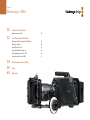
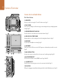
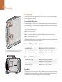
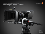
Installation and Operation Manual Blackmagic URSA Mac OS X™ Windows™ September 2014 Welcome Thank you for purchasing Blackmagic URSA! Since we released our first digital film camera a few years ago we have been privileged to have received some of the best guidance and feedback we have ever had for a new product! We all grew up admiring the work of the world's leading cinematographers and DOPs and it’s been an honor to spend hours in conversations with these legendary experts on the features we need to add to our cameras. Of course, everyone we speak to has good ideas also! All those exciting conversations have been put into the new URSA camera you have just purchased. We think it takes care of the needs of large film crews as well as having all the features you need if your operating in single person shooting. Its unique design allows you to replace the sensor, so add new imaging capability to it over time. What this also means is we could put more value into the screens, processing and cooling systems the camera has, because it does not need to be thrown away every time we develop a new sensor for it! So you get a built in large 10 inch on set monitor built in, dual CFast recorders that alternate recording so you can keep recording for as long as you want, as well as scopes, super strong metal design and much more. We hope you use your URSA to produce some of the world's most exciting films and television programming, music videos and commercials! We are extremely excited to see what creative work you produce and to get your feedback on new features you would like to see us add to URSA! Grant Petty CEO Blackmagic Design Contents Blackmagic URSA 5 Getting Started 17 Playback Introducing Blackmagic URSA 5 Attaching the Handle 5 Attaching a Lens 6 Powering Your Camera 7 Camera Assist and Audio Station Connectors 18 Mounting Batteries 7 Rear Panel Connectors 19 Bottom Panel Connector 19 8 About CFast Cards Playing Back Clips 17 18 Connectors Inserting a CFast Card 8 20 Camera Features Preparing a CFast Card for Recording 8 Work Station Buttons 20 Preparing CFast Cards on a Mac OS X Computer 8 Touch Screens 22 Preparing CFast Cards on a Windows Computer 9 Touch Screen Features 22 Status Strip 22 Power Indicator 22 10 Duration Display 22 Monitor Controls 10 Transport Display 23 Work Station Features 11 Media Timeline 23 10 Overview of Camera Controls DOP Station Camera Assist and Audio Station Work Station Features 12 12 24 Settings Front Panel 13 Camera Settings 24 Rear Panel 13 Audio Settings 26 Top Panel 13 Recording Settings 27 Bottom Panel 13 File Naming Convention 29 Display Settings 29 14 Recording Recording Clips 14 Recording Duration Table 15 31 Entering Metadata What is the Slate? 31 Contents Blackmagic URSA 32 Camera Video Output Monitoring using SDI 32 33 Post Production Workflow Working with Files from CFast 2.0 Cards 33 Editing your Clips 34 Using Final Cut Pro X 35 Using Avid Media Composer 36 Using Adobe Premiere Pro CC 36 Using Autodesk Smoke 2013 37 38 Blackmagic Camera Utility 39 Help 40 Warranty Getting Started 5 Getting Started Introducing Blackmagic URSA Blackmagic URSA is a user upgradable digital film camera designed for large crews or single camera operators. On the URSA camera, the controls are arranged into “stations” that make it easy for multiple people to access controls and use the camera all at the same time. The left side of the camera we call the DOP station and is where the director of photography would use the camera. On the other side of the camera we have the camera assist and audio stations where a camera assistant and an audio engineer can operate the camera. REC IRIS FO CU S PEA K DIS P ME NU SLA TE ZOOM DISP PGM The DOP station features a large 10 inch fold out monitor with buttons for recording and playback, plus display control for confirming focus and viewing SDI video from a switcher. Two CFast 2.0 recorders record HD or 4K video at up to 60 frames per second. A 5 inch touch screen is provided for camera settings, monitoring clips, camera status and scopes. The camera assist and audio station features a separate touch screen for camera settings, monitoring clips, status and scopes, plus audio meters and adjustment knobs. Professional BNC, TRS and XLR connectors are provided for external audio, headphones monitoring, LANC control, SDI in and out, reference in, timecode in and out, and power. Attaching the Handle Getting started with your Blackmagic URSA is as simple as attaching the handle, mounting a lens, and powering your camera. T I OU SD T V OU 12 0 IN -6 DIO AU -12 -18 -24 T SDI OU TE SLA -30 NU ME -36 T SDI P OU DIS -42 K PEA S -48 CU FO IN REF DE IN 1 CHLO SO ECO TIM 1 CHTE MU 2 CHLO SO 2 CHTE MU L T DE OU ECO TIM 2V +1 Attaching the top handle. IRIS R To attach Blackmagic URSA's handle to the camera body, simply slide the base of the handle along Blackmagic URSA's handle ridges and screw the handle to one of the 3/8" mounting points. Choose a mounting point that provides the best weight balance for your camera. 6 Getting Started SDI SDI Attaching a Lens OUT IN 0 -6 REF IN -12 -18 TIM ECO DE IN -24 -30 TIM ECO DE -36 OUT -42 -48 +12 V CH1 SOL O CH1 MUT E CH2 SOL O CH2 MUT E SDI OUT IRIS +12 FOC To remove the protective dust cap from the EF lens mount, hold down the locking button and rotate the cap counterclockwise until it is released. For the PL mount, rotate the PL locking ring counterclockwise. We recommend always turning off Blackmagic URSA prior to attaching or removing a lens. V OUT US PEA K DISP To attach an EF mount lens: MEN U SLA TE AUD IO IN Step 1. Align the dot on your lens with the dot on the camera mount. Many lenses have a visual indicator, for example a blue, red or white dot. Step 2. Twist the lens clockwise until it locks into place. Attaching and removing an EF mount lens on Blackmagic URSA EF. SDI To attach a PL mount lens: OU T SDI Step 3. To remove the lens, hold down the locking button, rotate the lens counterclockwise until its dot or indicator reaches the 12 o’clock position, and gently remove. IN 0 -6 REF IN Step 1. Open Blackmagic URSA's PL locking ring by rotating it counterclockwise until it stops. -12 -18 TIM ECO DE IN -24 -30 TIM ECO DE -36 OU T -42 -48 +12 V CH SOL1 O CH MU 1 TE CH SOL2 O CH MU 2 TE SDI OU T IRIS Step 2. Align one of the lens' four flange notches with the locating pin on the camera mount. Be sure to align the lens for easy viewing of the lens marks. +12 FO CU V OU S T PEA K Step 3. Tighten the PL locking ring by rotating it clockwise. DIS P ME NU SLA TE AU DIO IN Step 4. To remove the lens, rotate the locking ring counterclockwise until it stops, then gently remove the lens. When no lens is attached to the camera, the sensor is exposed to dust and other debris so you'll want to keep the dust cap on whenever possible. Attaching and removing a PL lens on Blackmagic URSA PL. 0 -6 DIO IN AU -12 7 Getting Started SDI OUT -18 -24 T U IO SD TE LA S -30 U EN M -36 ISP I IN D SD -42 AK PE S CU -48 IN F RE T I OU SD E OD IN 1 CHLO SO EC T V TIM OU 12 L T 0 E OD -6 OU EC IN TIM DIO AU -12 2V -18 +1 SDI IN Powering Your Camera 2 CHTE U M IS IR R Now that you've attached a lens, you'll need to supply power. The quickest way to power Blackmagic URSA is to connect external power using the supplied 12V AC adaptor. -24 T SDI 1 CHTE U M FO 2 CHLO SO OU REF IN TE SLA -30 To plug in External Power: NU ME -36 SDI P IN DIS -42 K PEA S CU -48 FO IN REF DE IN 1 CHLO SO ECO TIM 1 CHTE MU 2 CHLO SO 2 CHTE MU IRIS R Step 1. Connect the 12V AC adaptor plug to your mains power socket. L T DE OU ECO TIM V +12 Step 2. Connect the 12V AC adaptor’s 4 pin XLR connector to the 12-20V Power connector on the camera. TIMECODE IN If you have both external and battery power connected, only external power will be used. If you remove external power while a charged battery is connected, Blackmagic URSA will switch to battery power without interruption. Use the supplied 12V AC adapter to power your Blackmagic URSA. To turn your camera on: TIMECODE OUT Step 1. Press the Power button on Blackmagic URSA’s DOP or Camera Assist and Audio Stations. The touch screens and fold out monitor will now activate and the status strip will appear along the bottom of each touch screen. 0 SDI OUT -6 REC -12 SDI IN -18 -24 Step 2. Press and hold the Power button to turn your camera off. -30 1 US PEAK CFAST DISP MENU SLATE PUSH REF IN -36 TIMECODE IN -42 2 -48 Mounting Batteries PUSH ZOOM TIMECODE OUT CH1 SOLO DISP 12V IRIS FOCUS PEAK DISP MENU SLATE CH2 SOLO CH2 MUTE R IRIS FOCUS PEAK DISP MENU SLATE You can easily mount industry standard V-Mount or Gold Mount batteries to Blackmagic URSA. To mount a battery, you'll need to attach a third party V-Mount or Gold Mount battery plate to Blackmagic URSA's plate mount. Battery manufacturers such as IDX and Switronix provide battery plates with the correct molex 51353-1200 connector for plugging into URSA's molex power connector. You can purchase these battery plates from professional digital cinema and video equipment suppliers. PUSH PGM L CH1 MUTE Press the power button on Blackmagic URSA's work stations to turn the camera on. Press and hold to turn the camera off. T I OU SD T V OU 12 0 -6 O DI IN Step 1. Remove Blackmagic URSA's molex power cover from the rear plate by unscrewing the 4 corner screws. You'll now see Blackmagic URSA's 12 way molex 55959-1230 power connector. AU -12 -18 -24 T I OU SD E AT SL -30 NU ME -36 SP I IN DI SD -42 AK PE S CU -48 FO IN F RE E IN 1 CHLO SO OD EC TIM 1 CHTE MU 2 CHLO SO 1 CHTE MU S IRI R L T E Step 2. Connect Blackmagic URSA's 12 way molex 55959-1230 power connector to your third party battery plate. OU OD EC TIM 2V +1 Connecting a third party battery plate lets you mount V-Mount or Gold Mount batteries. Step 3. Screw the third party battery plate onto Blackmagic URSA's plate mounting points using 4 x M3 screws. Make sure the connector cable is tucked safely into the cable slot and not crushed between the plates when tightening. With the third party plate connected to your Blackmagic URSA, you can now mount a V-Mount or Gold Mount battery. Congratulations! You are now ready to insert CFast 2.0 cards and start recording! 12V About CFast Cards 8 About CFast Cards Inserting a CFast Card Blackmagic URSA uses CFast 2.0 cards to record HD or Ultra HD 4K video at up to 60 frames per second. To insert a CFast card into one or both of the CFast slots: Step 1. Open the fold out monitor to access the CFast slots and DOP work station. REC IRIS Step 2. With the label on the CFast card facing the touch screen, insert the card until you feel it lock into place. Push on the CFast card ejector button to eject the card. FOC US PEA K DISP MEN U SLAT E ZOOM DISP PGM Step 3. Power your camera. The status strip will display a moving dot while the camera checks the CFast card and then it will say READY. Additionally, the touch screen media timeline will display a time remaining indicator. IRIS Preparing a CFast Card for Recording FO CU S PE AK DIS CFast cards must be formatted as either HFS+ or exFAT. P ME NU Inserting a CFast 2.0 card into one of Blackmagic URSA's two CFast slots. SLA TE HFS+ is also known as Mac OS Extended. It is the recommended format as it supports "journaling". Data on a journaled CFast card is more likely to be recovered in the rare event that your media card becomes corrupted. HFS+ is natively supported by Mac OS X. ExFAT is supported natively by Mac OS X and Windows without needing to purchase any additional software. However exFAT does not support journaling. Preparing CFast Cards on a Mac OS X Computer Use the Disk Utility application included with Mac OS X to format your card in the HFS+ or exFAT formats. Remember to back up anything important from your CFast card as all data will be lost when it is formatted. Step 1. Connect the CFast card to your computer using a CFast 2.0 reader/writer or CFast drive, and dismiss any message offering to use your card for Time Machine backups. Step 2. Go to Applications/Utilities and launch Disk Utility. Step 3. Click on the disk icon of your CFast card and then click the Erase tab. Step 4. Set the Format to "Mac OS Extended (Journaled)" or "exFAT". Use Disk Utility on Mac OS X to erase your CFast card in the Mac OS Extended (Journaled) or exFAT format. Step 5. Type a Name for the new volume and then click Erase. Your CFast card will quickly be formatted and made ready for use. 9 About CFast Cards Preparing CFast Cards on a Windows Computer The Format dialog box can format a drive in the exFAT format on a Windows PC. Remember to back up anything important from your CFast card as all data will be lost when it is formatted. Step 1. Connect the CFast card to your computer using a CFast 2.0 reader/writer or CFast drive. Step 2. Open the Start Menu or Start Screen and choose Computer. Right-click on your CFast card. Step 3. From the contextual menu, choose Format. Step 4. Set the file system to "exFAT" and the allocation unit size to 128 kilobytes. Step 5. Type a volume label, select "Quick Format" and click "Start". Step 6. Your CFast card will quickly be formatted and made ready for use. Use the Format dialog box feature in Windows to format your CFast card in the exFAT format. Overview of Camera Controls 10 Camera Overview DOP Station 1 REC Monitor Controls 1. 10" LCD VIEWFINDER Large fold out on screen monitor, pivots for viewing at different camera heights. Pages 29 and 30. 2 2. RECORD BUTTON Press to start recording and press again to stop recording. Page 14. 0 SDI OUT -6 REC -12 SDI IN -18 -24 PUSH REF IN -30 1 -36 CFAST TIMECODE IN -42 2 -48 PUSH ZOOM TIMECODE OUT IRIS FOCUS CH1 SOLO DISP 12V PGM 3 ZOOM IRIS FOCUS PEAK DISP MENU SLATE L CH1 MUTE CH2 SOLO CH2 MUTE R IRIS FOCUS PEAK DISP MENU SLATE PUSH REC 3. PLAYBACK CONTROL BUTTONS Button for playback start and stop and skipping for the next or previous clip. Page 17. 4 IRIS FOCUS 4. ZOOM BUTTON This button zooms the LCD to 1:1 4K resolution to allow better focusing. Page 14. IR IS DISP 5 PGM 6 REC FO 5. DISP BUTTON CU S Turns on and off overlays, focus peaking and other on screen displays via the SDI monitoring output and 10 inch fold out monitor. Page 29. PE AK DI SP 6. PGM BUTTON Switches the monitor between the camera and the “program” video from the SDI input. Pages 19 and 32. 7. IRIS, FOCUS, REC AND TRANSPORT BUTTONS These controls allow camera operation when the monitor is folded closed, such as when shoulder mounted. 7 11 Camera Overview DOP Station Work Station Features 0 SDI OUT 1. MEMORY CARD SLOTS Insert CFast 2.0 type cards into the slots for record and playback. Page 8. -6 REC -12 SDI IN -18 -24 PUSH REF IN -30 1 -36 CFAST TIMECODE IN -42 2. TOUCH SCREEN The 5" touch screen display is used for monitoring, scopes and changing camera settings. Page 22. 2 -48 PUSH ZOOM TIMECODE OUT CH1 SOLO DISP 12V FOCUS PEAK DISP MENU SLATE CH2 SOLO CH2 MUTE R IRIS FOCUS PEAK DISP MENU SLATE PUSH IRIS PGM L CH1 MUTE 3. IRIS BUTTON Activates auto iris to set exposure when using compatible EF lenses. Page 20. 4. FOCUS BUTTON Activates auto focus when using an EF lens mount and compatible lens. Page 20. 5. PEAK BUTTON Turns focus peaking on to assist accurate manual focus. Page 20. 1 0 SDI OUT -6 6. DISPLAY BUTTON Toggles the touch screen between camera display and status display. Page 20. REC -12 SDI IN -18 -24 2 1 7. MENU BUTTON Opens the touch screen menu. Page 21. CFAST -30 -36 TIMECODE IN 2 -42 -48 PUSH ZOOM PUSH REF IN TIMECODE OUT 8. SLATE BUTTON Opens the slate so you can enter metadata using the touch screen. Page 21. CH1 SOLO DISP 12V IRIS FOCUS PEAK DISP MENU SLATE 3 4 5 6 7 8 9 CH2 SOLO CH2 MUTE R 9. POWER BUTTON Turns your Blackmagic URSA on and off. Page 21. IRIS FOCUS PEAK DISP MENU SLATE PUSH PGM L CH1 MUTE 12 Camera Overview Camera Assist and Audio Station Work Station Features 0 SDI OUT 1. AUDIO METERS Monitor your audio levels using the Ch 1 and Ch 2 audio meters. Page 21. -6 -12 SDI IN -18 -24 PUSH REF IN -30 -36 TIMECODE IN -42 PUSH -48 TIMECODE OUT CH1 SOLO CH1 MUTE CH2 SOLO 2. TOUCH SCREEN The 5" touch screen display is used for monitoring your camera image and scopes, and applying camera settings. Page 22. CH2 MUTE L 12V R IRIS FOCUS PEAK DISP MENU SLATE PUSH 3. AUDIO MONITORING MUTE AND SOLO Press these buttons to mute and monitor selected audio channels. Page 21. 1 0 SDI OUT 4. AUDIO LEVEL ADJUSTMENT KNOBS Adjustment knobs to set the recording levels for the left and right audio channels. Page 21. -6 -12 SDI IN -18 -24 PUSH 2 REF IN 5. HEADPHONES 1/4” jack output for headphones monitoring. Page 18. -30 -36 TIMECODE IN -42 PUSH -48 TIMECODE OUT 3 CH1 SOLO CH1 MUTE CH2 SOLO L 12V CH2 MUTE R 5 FOCUS 6 PEAK DISP MENU SLATE 7 PUSH 4 IRIS 6. LANC REMOTE 2.5mm stereo jack for LANC remote control. LANC supports record start and stop, iris and focus control. Page 18. 7. WORK STATION BUTTONS Activates various camera controls and the touch screen menu for adjusting settings. Page 20. 8. HD-SDI MONITORING OUT 3G-SDI connector for down converted 1080 HD output. Pages 18 and 30. 8 PUSH 9 PUSH 10 MENU SLATE 9. +12V POWER OUTPUT 4 pin XLR connector for powering accessories, such as an external viewfinder. Page 18. 10. XLR AUDIO IN XLR inputs for plugging in external balanced analog audio with selectable 48V phantom power. Page 18. PUSH 13 Camera Overview Front Panel 3 1. LENS MOUNT Lens mount for attaching lenses. EF mount shown in illustration. 4 5 1 2 6 7 8 Rear Panel 2. BATTERY PLATE MOUNT Mounting points and connector for attaching a third party V-Mount or Gold Mount plate. Page 7. 3. SDI IN 12G-SDI connector for SD, HD or Ultra HD video input. Page 19. 4. SDI OUT 12G-SDI connector for SD, HD or Ultra HD video output. Page 19. 5. REF IN BNC connector for plugging in an external reference signal. Page 19. 6. TIMECODE IN BNC connector for plugging in external timecode. Page 19. 7. TIMECODE OUT BNC connector for sending timecode to other professional video equipment. Page 19. 9 8. 12-20V POWER INPUT 4 pin XLR connector for plugging in external power. Page 19. Top Panel 10 9. 3/8" MOUNTING POINTS and TOP HANDLE Mounting points for attaching top handle and accessories. Bottom Panel 10. USB 2.0 USB 2.0 Mini-B port for updating internal software. Pages 19 and 38. IRIS REC FOCUS 11 11. 15" LIGHTWEIGHT ROD and VCT-14 BASE PLATE SUPPORT 15" LWS standard mounts for attaching rods, and mounting points for a VCT-14 quick release plate. Recording 14 Recording Recording Clips REC REC Press the REC button on Blackmagic URSA's monitor controls to begin recording immediately. Press REC again to stop recording. Choosing the Recording Format REC REC REC Your Blackmagic URSA records to lossless CinemaDNG RAW formats as well as various Apple ProRes compressed formats. You can select different recording formats and experiment to see which format best suits your workflow. To select your desired video format: Step 1. Press the Menu button. Step 2. Select the Recording menu and set the Recording Format using the selection arrows. ZOOM ZOOM ZOOM Step 3. Press the Menu button to exit. IR IS DISPDISP Your Blackmagic URSA is now ready to record in the video format you have selected. The current recording format is shown on the status strip on the touch screen. FO CU S ZOOM PGM DISP PE AK DIS PGM ZOOM P Blackmagic URSA Supported Recording Formats M EN U DISP PGM SL AT E DISP PGM To record a clip, press the REC button on the fold out monitor. PGM with focussing by zooming into The Zoom button assists your picture. IRIS FOCUS CinemaDNG 4K RAW 4000 x 2160p 23.98, 24, 25, 29.97, 30, 50, 59.94, 60. Apple ProRes 422 (HQ), ProRes 422, ProRes 422 LT and ProRes 422 Proxy 3840 x 2160p 23.98, 24, 25, 29.97, 30, 50, 59.94, 60. 1920 x 1080p 23.98, 24, 25, 29.97, 30, 50, 59.94, 60. Blackmagic URSA SDI Output Formats Rear SDI Input and Output 2160p 23.98, 24, 25, 29.97, 30, 50, 59.94, 60. 0 SDI OUT 1080p 23.98, 24, 25, 29.97, 30, 50, 59.94, 60. -6 REC -12 SDI IN -18 -24 REF IN SDI Monitoring Output 1080p 23.98, 24, 25, 29.97, 30, 50, 59.94, 60. -30 1 -36 CFAST TIMECODE IN -42 2 -48 PUSH ZOOM TIMECODE OUT IRIS FOCUS CH1 SOLO DISP 12V PGM Zoom Button IRIS FOCUS PEAK DISP MENU SLATE L CH1 MUTE CH2 SOLO CH2 MUTE R IRIS FOCUS PEAK DISP MENU SLATE PUSH REC PUSH REC The Zoom button on the fold out monitor helps you find sharp focus by zooming into your picture. In Ultra HD 4K mode, the monitor will show a 1:1 pixel view. Press the Zoom button on the fold out monitor to activate the focus zoom feature. Press again to zoom out to the standard view. 15 Recording Recording Duration Table 0 SDI OUT -6 SDI OUT -12 SDI IN -18 -24 12V OUT REF IN -30 -36 TIMECODE IN -42 -48 TIMECODE OUT 1 CH1 SOLO 12V L CH1 MUTE CH2 SOLO CH2 MUTE AUDIO IN R IRIS FOCUS PEAK DISP MENU SLATE 2 Below is a table showing the recording duration in minutes and seconds compared to format, frame rate and media size. The maximum recording time for a CFast card will vary depending on the data size of the card and the format and frame rate you choose. For example, the storage rate for Apple ProRes 422 (HQ) at 3840 x 2160 is approximately 880 Mbps. At 24 frames per second, you can record approximately 48 minutes of video on a 256GB CFast 2.0 card. Format CFast Card Frame Rate CinemaDNG RAW 4K ProRes 422 (HQ) ProRes 422 ProRes 422 LT ProRes 422 Proxy Duration Duration Duration Duration Duration 22:16 48:32 73:00 104:08 237:12 24 22:12 48:28 72:56 104:04 237:00 25 21:20 46:20 69:56 100:20 224:32 30 17:44 38:44 58:00 83:40 189:36 50 10:40 23:16 34:48 50:08 112:16 60 08:52 19:20 29:04 41:48 94:48 194:04 291:56 416:36 948:56 24 193:56 291:44 416:16 948:08 25 185:28 279:44 401:32 898:16 30 155:08 232:08 334:40 758:28 50 93:00 139:16 200:44 449:08 60 77:32 116:04 167:20 379:12 Ultra HD 256GB 23.98 4K HD 256GB 23.98 16 Recording Format CFast Card Frame Rate CinemaDNG RAW 4K ProRes 422 (HQ) ProRes 422 ProRes 422 LT ProRes 422 Proxy Duration Duration Duration Duration Duration 23.98 11:08 24:16 36:30 52:04 118:36 24 11:06 24:14 36:28 52:02 118:30 25 10:40 23:10 34:58 50:10 112:16 30 08:52 19:22 29:00 41:50 94:48 50 05:20 11:38 17:24 25:04 56:08 60 04:26 09:40 14:32 20:54 47:24 23.98 97:02 145:58 208:18 474:28 24 96:58 145:52 208:08 474:04 25 92:44 139:52 200:46 449:08 30 77:34 116:04 167:20 379:14 50 46:30 69:38 100:22 224:34 60 38:46 58:02 83:40 189:36 0 SDI OUT -6 SDI OUT -12 SDI IN -18 -24 12V OUT REF IN -30 -36 TIMECODE IN -42 -48 TIMECODE OUT 1 CH1 SOLO 12V L CH1 MUTE CH2 SOLO CH2 MUTE AUDIO IN R IRIS FOCUS PEAK DISP MENU Ultra HD 128GB 4K SLATE 2 HD 128GB Playback 17 Playback REC Playing Back Clips REC Once you have recorded your video, you can use the transport control buttons to play back your video. Press the Play button once for instant playback and you'll see your recorded video on the fold out monitor. Your clips can also be viewed on the touch screens and any display connected to the SDI outputs. Playback will continually play through all your recorded clips. REC The controls of your camera work just like a CD player, so pressing the Forward Skip button will skip to the start of the next clip. Press the Reverse Skip button once to go to the start of the current clip or press twice to skip back to the start of the previous clip. Hold the Forward or Reverse Skip button to play or reverse at 2x speed. ZOOM ZOOM You can also use the touch screens to scroll through your clips. For example, touch the media timeline and slide your finger let and right to select a clip to play. Play the clip by pressing Play on the fold out IR IS monitor transport controls. This is useful when you need to find a clip fast. ZOOM DISP DISP FO CU DISP S PE PGMPGM AK DI SP PGM Use the Play button on the fold out monitor to view your recorded clips. IRIS FOCUS 0 SDI OUT -6 REC -12 SDI IN REC -18 -24 PUSH REF IN -30 1 -36 CFAST TIMECODE IN -42 2 -48 PUSH ZOOM TIMECODE OUT IRIS FOCUS CH1 SOLO DISP 12V PGM IRIS FOCUS PEAK DISP MENU SLATE CH2 SOLO CH2 MUTE R IRIS FOCUS PEAK DISP MENU SLATE PUSH REC L CH1 MUTE Connectors 18 Connectors PUSH Camera Assist and Audio Station Connectors Blackmagic URSA's connectors, such as Headphones, LANC, +12V Power, 3G-SDI out and external XLR audio are conveniently located on the camera assist and audio station. The rear panel provides SDI In, SDI Out, reference BNC, and timecode BNC in and out connectors. Use the USB 2.0 connector located on the bottom panel for updating the internal software. 0 SDI OUT -6 -12 SDI IN -18 -24 PUSH REF IN -30 Headphones -36 TIMECODE IN -42 PUSH -48 TIMECODE OUT 12V L CH1 MUTE CH2 SOLO Monitor audio while recording or playing back clips by plugging your headphones into the 1/4” TRS stereo headphones jack. CH2 MUTE R IRIS FOCUS PEAK DISP MENU PUSH CH1 SOLO SLATE PUSH LANC Remote Control CH2 MUTE R IRIS FOCUS PEAK DISP MENU The remote port on your camera is used to remotely control record starting and stopping, iris and focus adjustments when using a compatible lens. SLATE 3G-SDI Out PUSH PUSH CH2 MUTE R IRIS FOCUS PEAK DISP MENU SLATE PUSH The camera assist and audio station features Headphones, LANC remote control, 3G-SDI Out, +12V Power Out and XLR Audio In connectors. PUSH The port is a 2.5 mm stereo jack using the standard LANC protocol. Use Blackmagic URSA’s down converted 3G-SDI output to send 1080 HD video to an external viewfinder when using the camera on your shoulder. This output can also be connected to routers, monitors, SDI capture devices, broadcast switchers and other SDI video equipment. +12V Power Output Use the 4 pin 12 Volt XLR connector for powering accessories, such as an external viewfinder. XLR Audio In Use the balanced XLR inputs to plug in external analog audio from professional equipment such as audio mixers, PA systems or even external microphones. Rear Panel Connectors 0 SDI OUT -6 SDI In 0 SDI OUT -12 -6 -12 SDI IN SDI IN -18 When connecting Blackmagic URSA to a switcher for live production, connect the switcher's program output to Blackmagic URSA's 12G-SDI input. Now you can view the switcher's program feed by pressing the PGM button on the fold out monitor. This input can also be used to connect to the playback output of an external recorder if used. You can then select between the camera and the external recorder by pressing the PGM button -24 REF IN PUSH -18 -30 1 -36 CFAST TIMECODE IN -42 2 -48 -24 TIMECODE OUT PEAK DISP MENU SLATE REF IN 12V CH1 MUTE L CH2 SOLO CH2 MUTE R IRIS FOCUS PEAK DISP MENU SLATE PUSH FOCUS PUSH CH1 SOLO IRIS PUSH M 19 Connectors -30 -36 TIMECODE IN -42 CH1 SOLO 12V L CH1 MUTE SDI Out CH2 SOLO CH2 MUTE R IRIS FOCUS PUSH -48 TIMECODE OUT PUSH Blackmagic URSA’s 12G-SDI output is used to send HD and Ultra HD 4K video to SDI equipment such PEAK DISP MENU SLATE as routers, monitors, SDI capture devices, and broadcast switchers. REF In Use the rear panel BNC connectors to input or output timecode, sync to an external reference signal, input or output 12G-SDI video. Connect external power via the 4 pin XLR connector. Synchronize Blackmagic URSA to a common reference signal, such as black burst or tri-level sync, by connecting to the REF In BNC connector. This lets you sync Blackmagic URSA to other SDI video equipment, for example, when using multiple cameras connected to a switcher. Timecode In Connect timecode from other professional audio and video equipment, such as audio mixers and clapper boards to Blackmagic URSA’s Timecode In BNC connector. This ensures audio and picture can be easily synchronized during post production. Timecode Out Send timecode from Blackmagic URSA to other professional video equipment by connecting to the Timecode Out BNC connector. Power Input +12-20V Use the 4 pin 12-20 Volt XLR connector to plug in power from external sources, such as power outlets, portable batteries and generators. Bottom Panel Connector Connect Blackmagic URSA to your Mac or Windows computer via the Mini-B USB 2.0 port to update the internal software. Lift the rubber cover to access the USB port. USB 2.0 Use the Mini-B USB 2.0 port to connect your Blackmagic URSA to your computer and update the internal software. Lift the rubber cover with your finger nail to access the USB port. Camera Features 20 Camera Features Work Station Buttons All of Blackmagic URSA's settings are easily adjusted using the work station buttons and touch screens. The buttons and touch screens on each station perform the same functions, but work independently. For example, a camera assistant can adjust settings from the camera assist and audio station, while the camera operator is setting a feature from the DOP station. 0 SDI OUT -6 -12 SDI IN -18 -24 PUSH REF IN -30 -36 TIMECODE IN -42 PUSH -48 TIMECODE OUT CH1 SOLO CH1 MUTE CH2 SOLO CH2 MUTE L 12V R IRIS FOCUS PEAK DISP MENU IRIS Button SLATE PUSH The Iris button activates the automatic aperture setting on compatible EF lenses. When using video dynamic range settings, a single press of the Iris button will set an average exposure based on the highlights and shadows in your shot. When using film dynamic range settings, pressing the Iris button sets your exposure to the brightest highlight in your shot. 0 SDI OUT -6 To set your aperture manually, press the forward and reverse skip transport buttons on the fold out monitor. -12 SDI IN -18 FOCUS Button -24 PUSH REF IN -30 -36 TIMECODE IN -42 PUSH -48 TIMECODE OUT CH1 SOLO 12V L CH1 MUTE When using an EF mount with an EF lens that supports electronic focus adjustments, press the Focus button to activate auto focus. A white focus square will appear on the fold out monitor. Anything within the square will be correctly focussed. When the lens is focussed, the square will disappear. Its important to know that while most lenses support electronic focus, some lenses can be set to manual or auto focus modes, and so you need to ensure your lens is set to auto focus mode. CH2 SOLO CH2 MUTE R IRIS FOCUS PEAK DISP MENU SLATE PUSH PEAK Button Adjust camera settings using the work station buttons on each side of Blackmagic URSA. Each station can be operated independently. Press the Peak button to activate focus peaking. The focus peaking feature creates a green edge around the sharpest parts of the image so you can easily confirm your focus. Focus peaking is not recorded to the CFast 2.0 cards, but can be displayed via the monitoring SDI output, and on URSA's fold out monitor, by activating overlays using touch screen menu. DISP Button Press the Disp button to cycle through the display modes on each touch screen. For example, pressing the Disp button lets you view the camera's status and scopes, or view your clips during recording and playback. PUSH 21 Camera Features MENU Button -6 Press the Menu button to activate the settings menu on the touch screen. Press Menu again to close. -12 PUSH 0 SLATE Button -18 Press the Slate button to activate the slate feature on the touch screen. Press Slate again to close. The slate feature lets you enter metadata for your clips and set your camera ID. See page 31. -24 PUSH -30 IRIS FOCUS -36 PEAK DISP MENU SLATE POWER Button PUSH -48 CH SOLO and MUTE Buttons CH1 MUTE CH2 SOLO During recording and playback, these buttons let you monitor your Ch 1 and Ch 2 stereo audio channels independently via headphones. For example, to monitor only Ch 1 audio, press the CH 1 Solo button or the Ch 2 Mute button. Press the button again to monitor both channels. CH2 MUTE R IRIS FOCUS PEAK DISP MENU PUSH Press the Power button to turn on your Blackmagic URSA. Press and hold to turn your camera off. -42 SLATE PUSH The Menu button opens the touch screen menu for access to many of the camera settings. CH 1 SOLO Button To monitor Ch 1 only, press the Ch 1 Solo button. 0 CH 1 MUTE Button SDI OUT -6 To mute the audio on channel 1 and monitor only channel 2, press the Ch 1 Mute button. -12 SDI IN CH 2 SOLO Button -24 To monitor Ch 2 only, press the Ch 2 Solo button. REF IN -30 0 SDI OUT CH 2 MUTE Button -6 -12 SDI IN -18 -24 PUSH REF IN -30 -36 To mute the audio on channel 2 and monitor only channel 1, press the Ch 2 Mute button. -36 TIMECODE IN -42 TIMECODE IN TIMECODE OUT CH1 SOLO 12V L CH1 MUTE CH2 SOLO -42 CH2 MUTE R IRIS FOCUS PEAK DISP MENU SLATE SLATE PUSH MENU PUSH -48 PUSH -18 CH1 SOLO 12V CH1 MUTE CH2 SOLO Turn each knob clockwise or counterclockwise to increase or decrease the recording level for each channel of audio. As you adjust each knob you'll see the corresponding audio meters respond. CH2 MUTE L PUSH Audio Level Adjustment Knobs -48 TIMECODE OUT R IRIS FOCUS PEAK DISP MENU SLATE PUSH Audio Meters The audio meters display the strength of your recorded audio. If your audio levels rise too high, your audio peaks can be clipped and you will hear distortion in your audio. Set and monitor levels of Left and Right audio channels using the adjustment knobs and audio meters. 22 Camera Features Touch Screens Each work station features a touch screen so you can monitor your recordings, view scopes, apply settings and activate camera features. By pressing the Disp button you can switch between viewing your clips during recording and playback, or viewing scopes and status information. Scopes are provided to assist with focusing, setting exposure and audio monitoring. Touch Screen Features Camera settings can be accessed using the the touch screen menus. Press the Menu button to open the touch screen settings. Navigate the settings by touching the icons on the left side of the screen. Status Strip Your chosen settings are always displayed on a status strip at the top of each touch screen, showing a convenient summary of your camera's settings. Power Indicator The power indicator displays a battery icon when using battery power, or an external power icon when plugged into external power via the 12-20 Volt XLR input. Duration Display The duration display provides a timecode counter for checking the duration of your clips and monitoring timecode during recording and playback. The counter displays a time sequence showing Hours:Minutes:Seconds:Frames and will progress through the sequence as you record or play back clips. The touch screens provide scopes to help set optimum exposure, focus and audio quality. The battery indicator is replaced by an external power icon when external power is plugged into the 12-20V XLR input. The displayed duration of each clip starts from 00:00:00:00 for the first clip, or from the end of the previous recorded clip. For example, if a clip stopped recording at 00:06:25:00, the next clip will start recording at 00:06:25:01. Clip duration is displayed on the touch screen, however time of day timecode is embedded into your clips for post production, so it's worth regularly checking the time settings in the Camera settings menu to make sure they are always accurate. When external timecode is connected to the Timecode In rear panel connector, external timecode is displayed. 23 Camera Features Transport Display The Transport display provides a bright colored icon that indicates which transport buttons are being used. The icon also provides a dropped frames alert if frames are dropped during recording, and displays FULL when recording has reached maximum capacity. Exposure Scope When the peak of the focus scope curve reaches its highest point, you'll know your image is in focus. The Exposure scope displays a histogram which shows the contrast between whites and blacks along a horizontal scale. The left edge of the histogram displays shadows, or blacks, and the far right displays highlights, or whites. When you close or open the lens aperture, you'll notice the information in the histogram moves to the left or right accordingly. To achieve optimum exposure, set your lens aperture so the information is distributed towards the right of the histogram and curves to a point at the bottom right edge. This is known as ETTR, or exposing to the right. Focus Scope The Focus scope displays a bell curve that moves up and down as you focus and defocus your lens. The height of the curve depends on the amount of detail in your picture. For example, in images containing lots of detail, the curve will be higher and more pronounced. When the curve peaks relative to the amount of detail in your image, you'll know your image is in perfect focus. Audio Scope The Audio scope displays a continually updating waveform of the previous 3 seconds of recorded audio. If you hear a loud sound while recording, you can easily check if your audio is clipped because the waveform will display red tips on the waveform spikes. You can make adjustments to avoid clipping by turning the audio level adjustment knobs counterclockwise until the audio meter stops rising above 0dB. Media Timeline The dropped frames alert indicates when your CFast card is dropping frames during recording. The red tips on the audio scope waveform indicate when your audio has clipped. The media timeline displays the recording and playback status of your CFast cards. The dot and clip indicators illuminate different colors depending on use: Red when writing to the card, Green when reading the card, and Yellow in the event of a card error. As a new clip is recorded, the active slot displays a new clip on the timeline. The time remaining indicator at the end of each timeline displays the remaining minutes and seconds of recording time for each CFast card and displays FULL when a card reaches maximum capacity. When a card is full and you have an empty CFast card in the second slot, Blackmagic URSA will automatically record to the other CFast card. To play a selected clip, press the Play button on the fold out monitor transport controls, or on the outside of the door. Settings 24 Settings Camera Settings To configure camera settings on your Blackmagic URSA, select the Camera touch screen menu, then touch the relevant arrows and icons for your desired setting. Camera ID If using more than one Blackmagic URSA, it's helpful to set each camera's ID which will be included with any metadata recorded with your clips. Set the Camera ID with the touch screen keyboard. Select Enter to save your Camera ID, or Cancel to discard any changes. Setting Date and Time To configure camera settings on your Blackmagic URSA, select the Camera touch screen menu. To set date and time on your Blackmagic URSA, touch the + or - icons to change the year, month and day settings. Time is set to 24 hour format. To set the time, touch the + and - icons to make adjustments. If traveling with your Blackmagic URSA, remember to change the date and time to local time zones. If you have your Blackmagic URSA stored for long periods, the time may need to be reset. It is always a good idea to check the time and date prior to recording. When connecting your camera to your computer via USB and launching Blackmagic Camera Utility, Blackmagic URSA’s time is synced to your computer time. ISO To adjust the ISO settings, touch the ISO arrow icons. ISO settings are helpful when you are shooting in a variety of light conditions. The optimum ISO setting for Blackmagic URSA EF and PL is 400ASA. Depending on your situation, however, you may choose a lower or higher ISO setting. For example, in low light conditions 800ASA can be suitable but may introduce some visible noise. In bright conditions 200ASA can provide richer colors. Set the camera ID using the touch screen keyboard. The keyboard appears when you touch the Camera ID text area. 25 Settings White Balance To adjust the White Balance settings, touch the White Balance arrow icons. Your Blackmagic URSA includes 6 white balance presets for a variety of color temperature conditions. These are: 3200K for tungsten light 4500K for fluorescent light 5000K, 5600K, 6500K and 7500K for a variety of daylight conditions such as time of day. The Camera settings screen. Every light source emits a color. For example, a candle flame emits a warm color, and an overcast sky emits a cool color. White balance settings are used to color balance your image so white stays white. For example, when shooting under tungsten lamps which emit a warm light, selecting 3200K adds some blue to the image. This balances the color so white is accurately recorded. Color balance settings can also be used for creating color effects. For example, setting your white balance to 7500K can significantly warm your picture to create an intimate mood. Shutter Angle To adjust the Shutter Angle settings, touch the Shutter Angle arrow icons. Shutter Angle defines the level of motion blur in your video, and can be used to compensate for varying light conditions. 180 degrees is the optimum shutter angle for capturing a satisfying motion blur in most conditions. However as lighting conditions change, or the amount of movement in your scene increases, you may decide to adjust accordingly. For example, 360 degrees is considered 'wide open' and allows maximum light onto the sensor. This is useful for low light conditions with subtle movement in your scene. Alternatively, if shooting motor sport with rapid movement, a narrow shutter angle will provide minimal motion blur for sharper, crisper images. When shooting 24p in countries with 50 hertz power supplies, 172.8 degrees will minimize potential flickering from 50Hz light sources. 26 Settings Audio Settings To adjust audio input and monitoring settings on your Blackmagic URSA, select the Audio touch screen menu, then touch or slide the relevant arrows and slider icons. Microphone Input Microphone Input adjusts the recording levels for Blackmagic URSA’s built in microphone. Move the audio slider left or right to decrease or increase levels. The built in microphone records to audio channels 1 and 2 when no external audio source is connected. Channel 1 and 2 Input Levels Record channel 1 audio on channels 1 and 2 by selecting Yes on the Ch2 uses Ch 1 Input setting. Set the external audio input levels for Ch 1 and 2 by touching the relevant left and right arrow icons. External audio connectors support line level or microphone level with 48V phantom power. It's important to select the appropriate level to avoid your external audio sounding almost inaudible, or too hot and distorted. Level settings include Internal Mic, External Mic and Line. Channel 1 Input Level Move the Ch 1 Input slider icon left or right to decrease or increase the channel 1 audio level. When connected, the external channel 1 XLR input overrides the built in microphone and is recorded to audio channel 1. Channel 2 uses Channel 1 Input Select Yes if you want to record channel 1 external audio to channels 1 and 2. Select No if you want channel 1 audio to remain on one channel only. Channel 2 Input Level Move the Ch 2 Input slider icon left or right to decrease or increase the channel 2 audio level. When connected, the external channel 2 XLR input overrides the built in microphone and is recorded to audio channel 2. Headphone and Speaker Volume Touch the headphone or speaker volume icon and drag left or right to increase or decrease audio monitoring levels. When headphones are connected, the headphone setting is displayed. When no headphones are detected, the speaker setting is displayed. Headphones are active when recording or playing a clip. The built in speaker is active only during playback. 27 Settings Recording Settings To set the video format recorded to your CFast 2.0 cards, select the circular record icon on the touch screen menu, then touch the relevant arrow icons. Recording Format Select between CinemaDNG 4K RAW and ProRes recording formats by touching the recording format arrow icons. Dynamic Range Adjust the Dynamic Range setting by touching the dynamic range arrow icons. Choose between CinemaDNG 4K RAW and ProRes recording formats using the Recording touch screen menu. Blackmagic URSA has two dynamic range settings: Film The Film setting shoots video using a log curve giving you 12 stops of dynamic range and maximizes the information in your video signal to help you get the most out of color grading software, such as DaVinci Resolve. When recording in CinemaDNG RAW formats, only the film dynamic range setting is available. Video The Video setting uses the REC709 color standard for high definition video. This lets you work faster by recording directly to the compressed video formats your camera supports, which are compatible with popular post production software. Frame Rate Adjust the Frame Rate setting by touching the frame rate arrow icons. Your Blackmagic URSA has 8 different frame rate settings for shooting common film and video frame rates including 23.98, 24, 25, 29.97, 30, 50, 59.94 and 60 fps. When recording high frame rates for slow motion playback, you'll need to ensure your editing software does not conform your clips frame rate to your project settings frame rate. For example, if you're editing using DaVinci Resolve 11, you'll need to set the correct mixed frame rate conform settings when you first set up your DaVinci Resolve edit project. Go to Master Project Settings/Conform Options and set the Mixed Frame Rate setting to None. This will ensure DaVinci Resolve maintains the slow motion you intended. 28 Settings Time Lapse Interval This setting activates the time lapse feature to automatically record a still frame at the following intervals: Frames: 2 - 10 Seconds: 1 - 10, 20, 30, 40, 50 Minutes: 1 - 10 For example, you can set the camera to record a still frame every 10 frames, 5 seconds, 30 seconds, 5 minutes etc. Use the Recording touch screen menu to set time lapse intervals when recording a time lapse clip. The time lapse feature offers many creative options. For example, if the time lapse interval is set to record a frame at 2 frame intervals, this will give your recorded video a high speed effect when played back. The format of each still frame is based on your recording format, so if you set the camera to record in 4K ProRes HQ, the Time Lapse setting will maintain this format. The frame rate will be based on the recording frame rate you have set, i.e., 24fps. This is so your time lapse footage can be easily incorporated into your post production workflow. When the REC button is pressed in time lapse mode, the timecode counter updates when a frame of video is recorded. To set the Time Lapse Interval setting, touch the time lapse interval arrow icons. Remember to set the time lapse feature to Off when you want to record at standard speed. 29 Settings File Naming Convention Clips are recorded to your CFast cards in the CinemaDNG RAW format or to a ProRes QuickTime movie, depending upon which recording format you have chosen. Blackmagic URSA uses the following file naming convention when recording video. [Camera ID]_[Reel Number]_[yyyy-mm--dd]_[hhmm]_C[Clip number].mov The table below shows an example of how this would appear on the camera's touchscreen: Set the dynamic range of your touch screen display using the Display settings. This feature lets you view your recording in Video dynamic range, even if your Recording settings are set to Film dynamic range. BMC01_1_2014-08-08_1631_C0002.mov QuickTime Movie Filename BMC01_1_2014-08-08_1631_C0002.mov Camera ID BMC01_1_2014-08-08_1631_C0002.mov Reel Number BMC01_1_2014-08-08_1631_C0002.mov Date (2014 Aug 08) BMC01_1_2014-08-08_1631_C0002.mov Time (16:31pm - 24hrs) BMC01_1_2014-08-08_1631_C0002.mov Clip Number For CinemaDNG files, the folder of the image sequence will also be named the same way. Display Settings To adjust the Display settings for a touch screen, select the Display touch screen menu, then touch or slide the relevant arrows and sliders. The DOP station touch screen also sets the dynamic range and SDI overlay options for the fold out monitor. When overlays have been set to On using the work station touch screen, Press the Disp button on the fold out monitor to enable overlays on the fold out monitor. Dynamic Range Blackmagic URSA’s fold out monitor and touch screens let you view your video as you are recording. You can set the display dynamic range by selecting Video or Film settings. The Display settings dynamic range is independent of the Recording settings dynamic range. This means you can monitor your video with the display set to video even when the recording format is set to film! To adjust the Display settings dynamic range, touch the dynamic range arrow icons. Brightness Move the Brightness setting slider icon left or right to adjust brightness for each touch screen. 30 Settings Zebra To activate and adjust the Zebra setting, touch the left and right zebra arrow icons. The Zebra setting helps you achieve optimum exposure by displaying diagonal lines across any part of the video that exceeds the set zebra level. For example, setting the zebra to 100% lets you see which areas of the picture are over exposed. Setting the zebra to 75% is a helpful method for achieving optimum exposure for skin tones. To achieve optimum exposure, simply open the lens aperture until the zebra pattern appears, then gradually close the aperture one f-stop at a time until the zebra pattern is no longer visible. Display settings screen with Zebra set to 100%. This will let you see which areas of your image are over exposed. To achieve a balanced exposure, you may need to decide which areas of your picture to leave over exposed. Car headlights and extreme highlights are a good example of what can often be left over exposed. SDI Overlays You can monitor your video with overlays on an external viewfinder or display via Blackmagic URSA’s HD-SDI Monitoring Out connector. The SDI Overlay setting lets you display useful information. Touch the SDI overlay arrow icons to select the overlays to display, or set to OFF for a clean feed. All: displays both frame guides and recording information. Status: displays only the recording information, such as f-stop number, frame rate, battery life etc. Guides: displays only the frame guides. Off: gives you a clean feed. Your selected overlays can also be viewed on Blackmagic URSA's fold out monitor by pressing the Disp button on the monitor control buttons. SDI Overlays set to display on an external viewfinder or monitor via URSA's down converted 1080 HD output. Your selected overlays can also be viewed on URSA's 10" fold out monitor. Image Stabilizer When using an EF lens mount, Blackmagic URSA supports the image stabilizer (IS) feature found in many EF lenses. Simply set the Stabilizer switch to ON to use it with your camera. If your lens also features a Stabilizer Mode switch, set it to the appropriate mode for still shots or for movement. When using battery power, the camera will only activate the image stabilizer while recording, as the lens draws additional power to operate the image stabilizer. When external power is connected to the camera, the image stabilizer will be active any time you set the lens stabilizer switch to ON. Entering Metadata 31 Entering Metadata What is the Slate? Blackmagic URSA's touch screens have many purposes, one of which is to allow you to easily log metadata directly into the camera using the Slate feature. Metadata is stored in the recorded files and is easily accessed by editing software. Step 1. Press the Slate button below the touch screen to make the slate appear. SDI OUT Step 2. To enter or change details, touch the text you wish to change and a touch screen keyboard will appear. Type in the desired information and touch Save. Step 3. If you want the scene, shot or take number to auto-increment, touch the corresponding autoincrement icon so it is illuminated. Touch it again to turn off the auto-increment feature. Log metadata directly into the camera using the Slate feature. SDI IN Entering words into the Keywords field will allow you to use them as search terms in your library database. This may be particularly useful for large projects where you have lots of material. The use of keywords narrows down the number of clips to search through, saving valuable time when you are editing. REF IN All metadata is compatible with popular software such as Final Cut Pro X and DaVinci Resolve. TIMECODE Select the auto-increment icon if you want the scene, shot or take number to auto-increment. TIMECODE 0 SDI OUT -6 -12 SDI IN -18 -24 PUSH REF IN -30 IRIS 1 FOCUS PEAK DISP MENU CFAST SLATE -36 TIMECODE IN -42 2 PUSH -48 TIMECODE OUT CH1 SOLO 12V FOCUS PEAK DISP MENU SLATE Press the Slate button to activate the Slate feature on Blackmagic URSA's touch screen. CH1 MUTE CH2 SOLO CH2 MUTE R IRIS FOCUS PEAK DISP MENU SLATE PUSH IRIS L Camera Video Output 32 Camera Video Output Monitoring using SDI Blackmagic URSA's down converted 3G-SDI Out connector always outputs 1080 HD video so you can easily connect to routers, monitors, SDI capture devices, broadcast switchers and other SDI devices. The 12G-SDI Out connector on the rear panel supports 6G-SDI, so it can be used to connect to any SDI monitor as well as 4K switchers such as ATEM Production Studio 4K. Connecting to Video Switchers The SDI outputs allow you to use your camera for live television production. You can connect the rear panel SDI output directly to production switchers for live production work, or to ATEM Camera Converters to convert your signal to optical so you can send it hundreds of meters to a broadcast truck on location. 0 IN -6 DIO AU -12 -18 SDI -24 OUT TE SLA -30 When connected to a switcher, you can easily view the switcher's program output on your Blackmagic URSA's 10 inch viewfinder. To do this, first connect the switcher to Blackmagic URSA's rear panel 12G-SDI input. Now press the PGM button on the 10 inch viewfinder. To switch back to the camera image, simply press the PGM button again. NU ME -36 SDI P IN DIS -42 K PEA US -48 FOC IN REF DE IN 1 CH O SOL ECO TIM 1 CHTE MU 2 CH O SOL 1 CHTE MU IRIS R L DE OUT ECO TIM Connecting to Monitors SDI monitoring can be really handy when accessing the fold out monitor is impractical, such as when secured high on a jib arm, on a crane, or mounted on a vehicle. 0 -6 DIO IN AU -12 -18 Monitoring information is displayed via your HD-SDI Monitoring Out connector by adjusting the SDI Overlay settings in the Display settings menu. SDI overlays provide frame guides and information such as recording details and camera settings. If you simply want to monitor your shots, you can always turn overlays off for a clean SDI output. -24 T U IO SD ATE SL -30 0 U EN M -36 -6 DIO DIS -42 -12 AK PE -18 S -48 CU FO IN F RE E OD IN 1 CHLO SO EC M TI 1 CHTE U M 2 CHLO SO 1 CHTE U M IS IR -24 T U IO SD R ATE SL -30 U EN M -36 P I IN DIS SD T E OD -42 L AK PE OU EC M TI IN AU P I IN SD S -48 CU FO IN F RE E OD IN 1 CHLO SO EC M TI T E OD 1 CHTE U M 2 CHLO SO 1 CHTE U M IS IR R L OU EC M TI You can connect the 12G-SDI output to any 1080 HD or Ultra HD live production switcher. You an also view the switcher's program output on URSA's fold out monitor by connecting it to the 12G-SDI input, then pressing the PGM button on the 10 inch viewfinder to monitor the "program" input. Connect the camera's SDI output to SDI monitors or to a Blackmagic SmartScope Duo 4K for live waveform monitoring. Post Production Workflow 33 Post Production Workflow Working with Files from CFast 2.0 Cards To import your clips from a CFast 2.0 card: Step 1. Remove the CFast card from your Blackmagic URSA. Step 2. Mount the CFast card to your Mac OS X or Windows computer using a CFast 2.0 reader/writer or CFast drive. Edit directly from your CFast card by removing it from your camera and mounting it on your computer using a CFast 2.0 reader/writer or CFast drive. Step 3. Double click on the CFast card to open it and you should see folders that contain your CinemaDNG RAW image files or a list of QuickTime movie files. Depending on the format you chose to record in, you might have a mixture of files, but they will all use the same naming convention. Step 4. Now you can simply drag the files you want from the CFast card onto your desktop or another hard drive, or you can access the files straight from the CFast card using your editing software. CinemaDNG RAW files are saved to the CFast card as separate DNG images for each frame. This is an open format and you can use many software applications to view your RAW 4K images as a video sequence. Step 5. Before you unplug the CFast card from your computer, it's always a good idea to eject safely using either Mac OS X or Windows first. 34 Post Production Workflow Editing your Clips To edit your clips using your favorite editing software, you can copy your clips to an internal/external drive or RAID and then import your clips into the software. Or import your clips directly from your CFast card using a CFast 2.0 reader/writer or CFast drive. VIDEO DATA RAW FILM DATA Using RAW Files with DaVinci Resolve CinemaDNG RAW clips may appear washed out or over exposed due to the high levels of information within them. To edit your RAW clips, they first need to be converted with a look that emulates standard video, or you can perform a full grade, then edit your fully graded clips. You can perform a basic conversion by importing your RAW clips into DaVinci Resolve and applying a look up table (LUT). The LUT will apply a basic color grade to emulate a standard video appearance. The graded clips are typically exported using ProRes settings and used as proxies until the final color grade, which will occur after the edit. To convert your RAW clips using DaVinci Resolve: Step 1. Create a new project and set your video resolution and frame rate to match your RAW video clips, or your intended delivery. In this example we’ll use the 2160p format with a frame rate of 25. RAW wide dynamic range - a wide dynamic range is captured with all details preserved. Step 2. If using clips with high frame rates for slow motion, set your Master Project Settings/Conform Options/Mixed Frame Rate to None. Step 3. Import your CinemaDNG RAW clips into the Media Pool. Step 4. Go to Project Settings and set your Input Settings to Scale Entire Image to Fit. Step 5. Go to Project Settings/Camera Raw and select CinemaDNG from the dropdown menu. Set the Decode Using setting to Project. Step 6. Select the White Balance setting most suitable for your material. Step 7. Set Color Space to BMD Film and set Gamma to BMD Film, or BMD Film 4K. To apply the LUT, go to Project Settings/Look Up Tables, and set 3D Output Look Up Table to Blackmagic Production Camera 4K Film to Rec709. This will apply the LUT to every shot in the timeline. Click on the Color tab and check the results. The images should exhibit improved color and contrast. Final color graded shot - The details are enhanced and the highlights are managed so your shots look cinematic! 35 Post Production Workflow At the very minimum do a quick check of the timeline for shots with excessive exposure or color issues. When you're satisfied with the appearance of the clips in the timeline, you’re ready to export your clips to ProRes. To export your clips: Step 1. Click on the Deliver tab, go to the Easy Setup menu and select Export to Final Cut Pro. By default this preset will render using Apple ProRes 422 (HQ). Step 2. Set the Render Timeline As setting to Individual Source Clips. Step 3. Ensure Render Each Clip With a Unique Filename is deselected. Step 4. Enable the Render Audio checkbox, select your audio channels and set to a bit depth of 24. Step 5. Under Render Job To: click Browse. Choose a new folder for your converted clips. Step 6. Click Add Job. Step 7. Click Start Render. DaVinci Resolve project settings.. Upon completion of the render you will have a folder that contains each individual clip from the Resolve timeline. The converted clips can now be imported into your editing software. You can always make adjustments to your grade by exporting an XML from your editing software. Using Final Cut Pro X To edit Apple ProRes 422 (HQ) clips using Final Cut Pro X, you need to create a new project and set a suitable video format and frame rate. This example uses ProRes 422 (HQ) 1080p25. Step 1. Launch Final Cut Pro X, go to the Menu bar and select File/New Project. A window will open containing project settings. Step 2. Name your project and select the Custom checkbox. Step 3. Set the Video Properties settings to 1080p HD, 1920x1080 and 25p. Step 4. Set your Audio and Render Properties settings to Stereo, 48kHz, and Apple ProRes 422 (HQ) Step 5. Click OK. Final Cut Pro X project settings. To import your clips into your project, go to the Menu bar and select File/Import/Media. Choose your clips from your CFast card. You can now drag your clips onto the timeline for editing. 36 Post Production Workflow Using Avid Media Composer To edit your DNxHD clips using Avid Media Composer 8, create a new project and set a suitable video format and frame rate. For this example, clips are set using DNxHD 1080i59.94. Step 1. Launch Media Composer and the Select Project window will appear. Click the New Project button. Step 2. In the New Project window name your project. Step 3. Go to the Format drop down menu and select 1080i/59.94. Step 4. Go to the Color Space drop down menu and select YCbCr 709. Step 5. Go to the Raster Dimension drop down menu and select 1920x1080. Click OK. Step 6. Select Tools>Background Services and click the "Start" button if background services are not already running and then click "OK." Step 7. Select the media bin where you wish to import your files. Step 8. Select File>AMA Link... and select the files that you wish to import and then click "OK." Setting the project name and project options in Avid Media Composer 7. When the clips appear within the media bin you can drag your clips onto the timeline and begin editing. Using Adobe Premiere Pro CC To edit your Apple ProRes 422 (HQ) clips using Adobe Premiere Pro CC, 2014 release, you need to create a new project and set a suitable video format and frame rate. For this example, clips are set using ProRes 422 (HQ) 1080p25. Step 1. Launch Adobe Premiere Pro CC. In the Welcome window select Create New/New Project. A window will open containing project settings. Step 2. Name your project. Choose the location for your project by clicking Browse and selecting your desired folder. Once you’ve selected your location folder click OK in the Welcome window. Step 3. Go to the Adobe Premiere Pro CC Menu bar, select File/Import and choose the clips you want to edit. Your clips will appear in the Project window. Step 4. Drag the first clip you wish to edit onto the New Item icon at the bottom right of the Project Window. A new sequence will be created matching your clip settings. You can now drag your clips onto the sequence timeline for editing. Setting the project name and project options in Adobe Premiere Pro CC, (2014). 37 Post Production Workflow Using Autodesk Smoke 2013 To edit your clips using Autodesk Smoke 2013, create a new project and set a suitable video format, bit depth, frame type and frame rate. This example uses ProRes 422 (HQ) 1080p25. Step 1. Launch Smoke and the Project and User Settings window will appear. Click on the New button under the project heading. Step 2. The Create New Project window will open. Name your project. Step 3. From the resolution drop down menu, select 1920x1080 HD 1080. Step 4. Make sure bit depth is set to 10-bit and frame type is Progressive. Step 5. From the Config Template drop down menu select [email protected]. Step 6. Leave the Preferred Format set to ProRes 422 (HQ) and click Create. Step 7. Click on the New button under the User heading. Step 8. When the Create New User Profile window opens, type your user name and click Create. Step 9. When the Project and User Settings window reopens, click the Start button. Step 10. From the menu bar, select File>Import>File and select your clips to import. Step 11. Once the clips appear in the media library you can drag your clips onto the timeline and begin editing. Setting the project name and project options in Autodesk Smoke 2013. Blackmagic Camera Utility 38 Blackmagic Camera Utility How to Update Your Camera Software on Mac OS X After downloading the Blackmagic Camera Utility software and unzipping the downloaded file, open the resulting disk image to reveal its contents. Launch the Blackmagic Camera Installer and follow the on screen instructions. How to Update Your Camera Software on Windows After downloading the Blackmagic Camera Utility software and unzipping the downloaded file, you should see a Blackmagic Camera Utility folder containing this PDF manual and the Blackmagic Camera Utility installer. Double-click the installer and follow the on screen prompts to complete the installation. How to Update the Camera Software After installing the latest Blackmagic Camera Utility on your computer, connect a USB cable between the computer and your Blackmagic URSA. The Mini-B USB 2.0 port is located on the bottom panel of your camera. Launch the Blackmagic Camera Utility and follow any on screen prompt to update the camera software. The Mini-B USB 2.0 port is used to update the camera software and can be found on Blackmagic URSA's bottom panel. Help 39 Help Getting Help The fastest way to obtain help is to go to the Blackmagic Design online support pages and check the latest support material available for your camera. Blackmagic Design Online Support Pages The latest manual, software and support notes can be found at the Blackmagic Design support center at www.blackmagicdesign.com/support. Contacting Blackmagic Design Support If you can't find the help you need in our support material, please use the "Send us an email" button on the support page to email a support request. Alternatively, click on the "Find your local support team" button on the support page and call your nearest Blackmagic Design support office. Checking the Software Version Currently Installed To check which version of Blackmagic Camera Utility software is installed on your computer, open the About Blackmagic Camera Utility window. On Mac OS X, open Blackmagic Camera Utility from the Applications folder. Select About Blackmagic Camera Utility from the application menu to reveal the version number. On Windows, open Blackmagic Camera Utility from your Start menu or Start Screen. Click on the Help menu and select About Blackmagic Camera Utility to reveal the version number. How to Get the Latest Software Updates After checking the version of Blackmagic Camera Utility software installed on your computer, please visit the Blackmagic Design support center at www.blackmagicdesign.com/support to check for the latest updates. While it is usually a good idea to run the latest updates, it is wise to avoid updating any software if you are in the middle of an important project. Warranty 40 Warranty 12 Month Limited Warranty Blackmagic Design warrants that this product will be free from defects in materials and workmanship for a period of 12 months from the date of purchase. If a product proves to be defective during this warranty period, Blackmagic Design, at its option, either will repair the defective product without charge for parts and labor, or will provide a replacement in exchange for the defective product. In order to obtain service under this warranty, you the Customer, must notify Blackmagic Design of the defect before the expiration of the warranty period and make suitable arrangements for the performance of service. The Customer shall be responsible for packaging and shipping the defective product to a designated service center nominated by Blackmagic Design, with shipping charges pre paid. Customer shall be responsible for paying all shipping charges, insurance, duties, taxes, and any other charges for products returned to us for any reason. This warranty shall not apply to any defect, failure or damage caused by improper use or improper or inadequate maintenance and care. Blackmagic Design shall not be obligated to furnish service under this warranty: a) to repair damage resulting from attempts by personnel other than Blackmagic Design representatives to install, repair or service the product, b) to repair damage resulting from improper use or connection to incompatible equipment, c) to repair any damage or malfunction caused by the use of non Blackmagic Design parts or supplies, or d) to service a product that has been modified or integrated with other products when the effect of such a modification or integration increases the time or difficulty of servicing the product. THIS WARRANTY IS GIVEN BY BLACKMAGIC DESIGN IN LIEU OF ANY OTHER WARRANTIES, EXPRESS OR IMPLIED. BLACKMAGIC DESIGN AND ITS VENDORS DISCLAIM ANY IMPLIED WARRANTIES OF MERCHANTABILITY OR FITNESS FOR A PARTICULAR PURPOSE. BLACKMAGIC DESIGN’S RESPONSIBILITY TO REPAIR OR REPLACE DEFECTIVE PRODUCTS IS THE WHOLE AND EXCLUSIVE REMEDY PROVIDED TO THE CUSTOMER FOR ANY INDIRECT, SPECIAL, INCIDENTAL OR CONSEQUENTIAL DAMAGES IRRESPECTIVE OF WHETHER BLACKMAGIC DESIGN OR THE VENDOR HAS ADVANCE NOTICE OF THE POSSIBILITY OF SUCH DAMAGES. BLACKMAGIC DESIGN IS NOT LIABLE FOR ANY ILLEGAL USE OF EQUIPMENT BY CUSTOMER. BLACKMAGIC IS NOT LIABLE FOR ANY DAMAGES RESULTING FROM USE OF THIS PRODUCT. USER OPERATES THIS PRODUCT AT OWN RISK. © Copyright 2014 Blackmagic Design. All rights reserved. ‘Blackmagic Design’, 'URSA', ‘DeckLink’, ‘HDLink’, ‘Workgroup Videohub’, ‘Multibridge Pro’, ‘Multibridge Extreme’, ‘Intensity’ and ‘Leading the creative video revolution’ are registered trademarks in the US and other countries. All other company and product names may be trade marks of their respective companies with which they are associated.