1
Multi Channel Audio/Video Pre - Amplifier
User's Manual
2
Contents
Placement and connection
4
Additional earth connection
5
Audionet Link
5
Polarisation of mains plug
5
Connecting the external power supply EPS
5
Audio/Video-Connections
7
First Steps
9
Usage front panel
11
Audionet System Remote Control
13
Setup
26
Menu Channel Setup
28
Menu Decoder Setup
30
Menu Global Setup
33
Menu Video Setup
34
Menu Bass Manager
35
Menu Delay Manager
37
Display
38
On Screen Display (OSD)
42
Progressive Scan Card
43
Overview video outputs
49
USB Audio
50
Security advice
54
3
Placement and connection
·
Important:
Warning! Please read this manual prior to operating the MAP 1 in order to
avoid damage on your valuable equipment.
Also, please make sure all units of your audio/video system are switched off while
connecting or disconnecting any cables to avoid damage of the input and/or output
sections of your units.
Please make sure that your Audionet MAP 1 is installed at a place that is sufficiently
ventilated to allow the heat to leave.
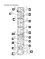
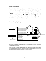
The mains input 17 *) is located at the back panel of the MAP 1. Please use the
provided power cord to connect the MAP 1 to mains. If you want to use a different
power cord make sure that it meets the specifications for your home country.
·
·
Important:
The electrical specifications at the back must meet the specifications of your
home country.
The mains switch at the back panel has to be switched off before connecting the
MAP 1 to mains. The MAP 1 is a Class I device and must be earthed. Please
ensure a stable earth connection. 'Phase'/'Hot pin' is marked at the back panel
(PHASE) 17 .
The MAP 1 is a stand by device. Please use the mains switch 17 at the back panel to
switch on the MAP 1. After a short time the display reads off or small dot to report
that the unit is in stand by mode now (see chapter 'Setup', section 'Global Setup', menu
item 'Set Stand By Text').
Only in case of extended absence (like vacations) or if massive trouble on mains power
is to be expected you should disconnect the unit from the mains. Switch off the MAP 1
with the mains switch at the back panel 17 . The display will go out.
·
·
*)
Important:
Before switching off the mains switch of the MAP 1, please make sure that all
units connected to the outputs of the MAP 1 are switched off, too.
Long term usage of the display set to maximum brightness (setting 100%) may
cause extended signs of wear resulting in a decay of contrast or brightness of
individual dots in the display. Do not use the display with a brightness set higher
than the factory default setting of 50% over a longer period of time (refer to
Chapter 'Remote Control', section 'Screen page 5')!
see numbers on page 'Overview of connections'
4
Additional earth connection
Optionally, there is a special cord available for an additional earth connection to be used
with earth connector 1 . Use the screw of earth connector 1 to connect the additional
ground cord to the MAP 1. Put the plug of the ground cord into a mains socket near
your power cord. The sound will be improved.
·
Tip:
We strongly recommend using the additional earth connection!
Audionet Link
In connection with other Audionet devices like AMP I, AMP II, AMP II MAX, AMP
III, AMP IV, AMP VII etc. your MAP 1 is able to switch on/off the complete system.
Please connect a Toslink plastic fibre cable from the Audionet-Link Output 8 at the
back of the MAP 1 to the Audionet-Link inputs of other Audionet devices. For further
instructions please read the user's manual of the other Audionet devices.
Polarisation of mains plug
The correct polarizing of mains is important for reasons of audio clarity and stability.
Therefore the Audionet MAP 1 indicates a wrong polarisation of the mains lead. While
powering up, the MAP 1 checks the mains polarisation. If you read
►
Attention:
◄
► Mains Phase incorrect ◄
switch off the MAP and then flip the plug in your wall outlet.
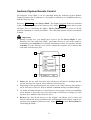
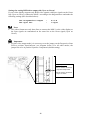
Connecting the external power supply EPS
Use the provided special cord to connect the optionally available EPS to the EPS-Input
2 at the back panel of the MAP 1. Connect both (!!) units (MAP 1 and EPS) with
mains. Switch on first the MAP 1 then the EPS with the mains switch at the back of the
units. The MAP 1 is now in stand by mode. You can start up the MAP 1 by pressing the
power key at the front panel, or the key Power On or Power Toggle on the
remote control.
To disconnect both units from the mains please make sure first, that the MAP 1 is
switched off to stand by mode using the power key at the front panel or the key
Power Off or Power Toggle on the remote control. Now you can disconnect the
units from the mains by switching off first the MAP 1, then the EPS using the mains
switch at the back panel of the units.
5
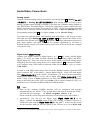
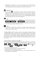
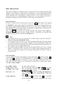
2
3
6
16
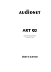
Marking mains phase
17
DVI video
output
Mains input and mains
power switch
(Y)
(CB)
15
(CR IN)
FBAS
14
S-Video
output
IN 2
Composite
video input
4
IN 1
S-Video
inputs
Additional earth Connector for the external DVI video
input
connector
power supply EPS
1
13
Digital output:
Digi Rec Select
Composite
video output
5
12
Digital inputs
1 to 7
RBACK
LBACK
11
Multi-Channel
analog output
AUDIO
USB
LINK
AUDIONET
10
8-Channel
analog input
CONTROL
USB
USB data interface
6
Audionet Link
connector
8
9
2-Channel Analog
inputs
Digital input 8
USB-Audio
7
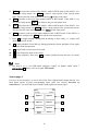
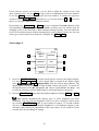
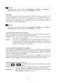
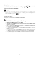
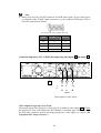
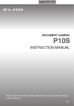
Overview of connections
Audio/Video-Connections
Analog Inputs:
Connect 2-channel analog sources to one of the two analog inputs 9 (Analog In LEFT
1/ RIGHT 1 or Analog In LEFT 2/ RIGHT 2). Both analog inputs are setup to pure
analog 2-channel signal routing by default. If you have the 2-channel analog outputs of
your DVD-Player, LaserDisc-Player, VCR or any other analog source connected to the
MAP 1 and want to use Dolby* Pro Logic IIx or DTS** Neo:6 for decoding Surround
encoded stereo material, switch internal decoder mode to Multi-Channel for the
corresponding analog input 9 (see chapter 'Setup', section 'Decoder Setup').
If you have the optional phono card installed, plug in the MM- or MC pickup of your
turn table into input Analog In LEFT 2/ RIGHT 2 9 and connect the chassis of the
turn table to the ground screw GND 1 . The phono card offers independent selection of
gain, input capacity and input resistance for optimal adjustments to all kinds of
available pickup systems. For further details please refer to the enclosed user's manual
of the phono card.
Digital Inputs (Digital Audio):
Connect your digital sources to digital inputs 1 to 7 12 . By factory default digital
inputs 1,2,3 and 5 are setup for multi channel decoding (Dolby Digital and DTS).
Digital inputs 4,6,7 and 8 are setup for stereo PCM signals (all default setting can be
changed by the user in the setup menus!). Use digital input 8 7 to connect the MAP 1
to a Computer using USB Audio to playback sound and music files (refer to chapter
'USB Audio').
In order to send DVD-Audio music data across the HighBit interface from the DVD
player Audionet VIP1) to the MAP 1, connect digital output 1 of the VIP with digital
input Digital Audio IN 1 of the MAP 1. Furthermore, you need a second connection
running from digital output 2 of the VIP to digital input Digital Audio IN 2 of the
MAP 1. Only in case of both connections are setup and the switch for the interface
mode on the back panel of the VIP is set to h-bit (refer to owner's manual of VIP), it is
possible to receive and decode DVD-Audio data with the MAP 1.
·
·
1
Note:
Data on the Audionet HighBit interface will be recognized and decoded
automatically by the MAP 1. If the second data connection is missing the MAP 1
will issue the error message:
► Check HighBit Cable 2 ◄.
Please check the correct setup and connection of both cables from VIP to MAP 1.
Alternatively, you can use the digital input Digital Audio IN 3 of the
MAP 1. Connect the datalink output of the VIP by using a common 'Firewire' or
'IEEE1396' cable with the Digital Audio IN 3 of the MAP 1. In this case the switch
for the interface mode on the back panel of the VIP has to be set to h-bit mode
Make sure your VIP supports the HighBit DVD-Audio interface. Software upgrades are available for older models.
7
(refer to owner's manual of VIP), to receive and decode DVD-Audio data with the
MAP 1.
External 8-Channel Analog Inputs:
Plug in analog multi channel sources (external decoder, DVD-Player with internal
decoder, SACD-Player etc.) into the 8-channel analog input 10 of the MAP 1.
·
Note:
The External 8-Channel Analog Input provides no signal processing at all, only pure
analog volume control!
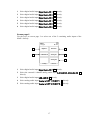
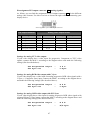
Pin assignment External 8-Channel Analog Input
Pin
Signal
Pin
Signal
1
Front Left
14
Ground Front Left
2
Center
15
Ground Center
3
Front Right
16
Ground Front Right
4
Subwoofer
17
Ground Subwoofer
5
Left Surround
18
Ground Left Surround
6
Right Surround
19
Ground Right Surround
7
Left Back
20
Ground Left Back
8
Right Back
21
Ground Right Back
Analog Outputs:
All analog outputs 11 are located in the section Analog Outputs in the right part of the
back panel.
Digital Outputs (Digital Audio Out):
Select DigiRec Select in the setup menu, which of the digital input 1 to 7 12 is
routed to the digital output 13 . The digital record select works independently,
therefore you can use digital out for recording while listening to a different source.
Video Inputs (Video In / S-Video In):
Plug in your cinch/composite video sources into video inputs IN 1 and IN 2 4 .
S-Video sources are to be connected to video inputs S-Video In 1 and S-Video In 2 15 .
Use the video inputs in any order as each of the 4 video inputs can be assigned to every
audio input (see menu 'Video Setup' and 'Channel Setup'). Even multiple assignments
8
are allowed, i.e. one and the same video input can be assigned to more than one audio
input.
Video Outputs:
The video signal assigned to the current audio input is available at the Video Out jacks;
cinch video at FBAS 5 and S-Video at S-VIDEO 14 . All video signals at the cinch
video inputs are converted to S-Video format by the internal 'Cinch Video to S-Video
Converter' and available at the output S-VIDEO. The On Screen Display (OSD) is
available at video outputs VIDEO 5 and S-VIDEO 14 .
Alternatively, both video inputs VIDEO IN1 and IN2 together with video output FBAS
can be re-defined as secondary component video (YUV) input (refer to chapter 'Setup'
section 'Set video input' and chapter 'Progressive Scan Card' for further details and
connection diagram).
DVI Video In-/Outputs:
The DVI video input and output sockets are both designed for analog and digital video
signals (DVI-I). If no progressive scan card is installed, the analog or digital input
signals of the DVI input socket are directly sent to the output socket (refer to chapter
'Setup' section 'Set video input' ).
·
·
·
Note:
Digital DVI video signals are not processed by the installed progressive scan card
but only routed through from input 3 to output 16 , if the option
Set Video Input :
DVI-Int. In
is selected.
Interlaced analog video formats, which are fed into a video 4 , S-Video 15 or DVI
analog input 3 can only be converted into a progressive digital DVI video format,
if the optional progressive scan card and the optional DVI Module are both
installed.
Please refer to chapter 'Progressive Scan Card' for detailed information about
connection and configuration of the optional Progressive Scan Card.
First Steps
The following provides a short overview of the first steps and their order to setup the
MAP 1. For any detailed description please refer to the sections 'Usage front panel' and
'Audionet System Remote Control Harmony One'.
After connecting your MAP 1 to the other components of your Hifi or Home Cinema
system (refer to section 'Audio / Video connections'), some setup options have to be
9
configured. Your MAP 1 needs information about the number of speakers, their
distances from the listening position and sensitivity to work with optimum performance.
The setup procedure is quite easy if you stick to the following order:
1. Number and size of speakers: Use key Bass Manager
(refer to chapters ' Audionet System Remote Control Harmony One' and 'Setup')
Select what kind of speakers you are using. Large refers to speakers that are
capable of reproducing the complete bass domain down to the lowest frequencies.
Use setting Small for bookshelf-type speakers or small sized design speakers that
are not capable to produce a rich bass foundation due to their construction.
According to these settings the MAP 1 determines automatically the amount of bass
information that is sent to each speaker. Due to the different calculating operations
that are needed for this bass management, the perceived volume level may vary
between different settings.
2. Distance of speakers to the listening position: Use key Delay Manager
(refer to chapters ' Audionet System Remote Control Harmony One' and 'Setup')
Measure the distance of each speaker to your listening position and enter the number
into the Delay Manager. Your MAP 1 automatically calculates the necessary delay of
each channel so that the music signals arrive at exactly the same time at your
listening position. As the delay settings are calculated and setup in real time, the
music signal may be influenced for the short moment of setting the new value.
3. Level setup: Use key TestTone
(refer to chapter ' Audionet System Remote Control Harmony One', section 'Screen
page 6')
The noise signal will support you to determine the correct level of each speaker, so
all perceived volumes are the same. This setup is necessary as different speakers
have different sensitivities causing different perceived volumes though the input
signal has the same level.
·
Note:
After adjusting the volume levels of all speaker channels we recommend to save
these settings to all input channels as a simple start up for further channel or source
dependent level settings. To save the current level settings to all input channels,
press the following keys on the remote control:
Save Setting à Ch- à
Now all input channels have the same volume level settings. Of course, you can
change these settings easily for each input channel independently if necessary. After
these 3 steps the most important global settings are done.
Following the global setup there are lots of options that are valid for each input channel
separately. These local settings are necessary to meet all the demands of different
source units connected to the inputs of the MAP 1 (please refer to section 'Setup',
subsection 'Channel Setup' for further details).
10
Usage front panel
There are four keys at the front panel to control the MAP 1. Although most of the setup
can be done using those keys, the included remote control provides much more comfort
(refer to sections ' Audionet System Remote Control Harmony One' and 'Setup').
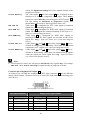
The power key is used to switch on/off the MAP 1. To change volume or any settings
in the setup menus, please press the up and down keys. With the set key you skip
through the menu items of the setup menus. If you press and hold the set key for more
than two seconds, it will get you to the next setup menu. For navigating through the
menus using the remote control, please refer to chapter ' Audionet System Remote
Control Harmony One', section 'Navigate through a menu'.
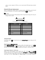
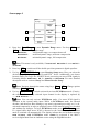
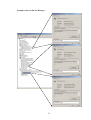
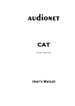
Example: Navigating through menus
set (short)
or Ch-
Level Setup
Channel Setup
key on remote control for
direct access of menu
Front
Center
Adjust Channel Offset Left Front
Adjust Channel Offset Center
Adjust Channel Offset Right Front
Adjust Channel Offset Right Surround
Adjust Channel Offset Right Back
Adjust Channel Offset Left Back
Adjust Channel Offset Left Surround
Adjust Channel Offset Subwoofer
Adjust Channel Offset LFE Mix
Internal Decoder
Set Video Input
Channel Offset Adjust
Set Listening Mode
Set Digital Filter
Set Dynamic Range
Set Dual Mono
Edit Channel Name
Surround
Back
Ch+
Subwoofer
LFE
Key on remote control for
direct access of function
set (long)
Listening Mode
Digital Filter
Dynamic Range
An overview of all menus and their functions is provided on the next page. Please refer
to example above as legend.
Before describing all menus and their menu items, the functions of the remote control
are explained in detail. Please use the remote control or, as alternative, the keys at the
front panel to setup your MAP 1 according to your preferences.
11
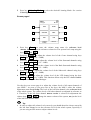
Overview of menu structure
RUN Mode
Level Setup
Channel Setup
Decoder Setup
Global Setup
Video Setup
Bass Manager
Delay Manager
Select Input
Set Listening Mode
Adjust Channel Offset Left Front
Adjust Channel Offset Center
Adjust Channel Offset Right Front
Adjust Channel Offset Right Surround
Adjust Channel Offset Right Back
Adjust Channel Offset Left Back
Adjust Channel Offset Left Surround
Adjust Channel Offset Subwoofer
Adjust Channel Offset LFE Mix
Internal Decoder
Set Video Input
Channel Offset Adjust
Set Listening Mode
Set Digital Filter
Set Dynamic Range
Set Dual Mono
Edit Channel Name
Set Dolby Pro Logic IIx mode for Multi-Channel
Set Dolby Pro Logic IIx mode for 2-Channel
Set DTS Neo:6 Mode
Convert 2-Ch PCM to
Set Output Phase
Set Standby Text
Set AutoStart
Dolby Digital EX Mode
Set Display Brightness
Set Digital Record Output
Set Lip Sync Delay
Set Video Input
Set TV System
Set Progressive Output
Set Sync Output
Set Speaker Size Front
Set Speaker Size Center
Set Speaker Size Surround
Set Speaker Size Back Surround
Set Cross Over Frequency Front
Set Cross Over Frequency Center
Set Cross Over Frequency Sur
Set Cross Over Frequency Back
Set High Pass Q-Factor Front
Set High Pass Q-Factor Center
Set High Pass Q-Factor Sur
Set High Pass Q-Factor Back
Subwoofer
Set Subwoofer Phase
Set Speaker Distance Left Front
Set Speaker Distance Center
Set Speaker Distance Right Front
Set Speaker Distance Right Sur
Set Speaker Distance Right Back
Set Speaker Distance Left Back
Set Speaker Distance Left Sur
Set Speaker Distance Subwoofer
Set Subwoofer Distance Offset
Set Distance Unit
12
Front
Center
Surround
Back
Subwoofer
LFE
Listening Mode
Digital Filter
Dynamic Range
Dolby / DTS Mode
Dim Display
DigiRec Select
Audionet System Remote Control
All functions of the MAP 1 can be controlled using the Audionet System Remote
Control Harmony One. Furthermore, it is possible to control up to 14 additional devices
with the Harmony One.
Press key Devices to enter Device Mode. The display now lists all devices included
in the current configuration of the Harmony One. Select MAP1 from the list to set the
Harmony One to controlling the MAP 1. Device Mode gives you access to all the
possible commands to control your MAP 1. The following explains all these commands
in detail.
·
Important:
During everyday use, you should never need to use the Device Mode of your
Harmony One, but control the MAP 1 (and other devices of your audio setup) by
customizing your Activities. For detailed information on how to customize and use
Activities on your Harmony One please consult the separate user's manual that
came with your Harmony One.
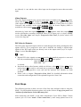
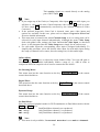
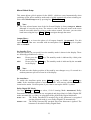
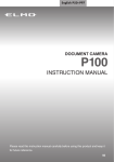
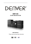
1
2
My Activities:
Mi 14:51
1/2 pages
Listen to CDs
Watch a DVD
3
3
CD with VIPG3
Options
Devices
4
5
1
Power key for use with Activities, turns all devices off that are included into the
current Activity. See separate user's manual of Harmony One.
2
Depending on the operational mode, the touch screen of the Harmony One shows a
list of Activities or Devices, help or infrared commands and any available listings.
3
If a menu or listing stretches over more than one screen page, use the corresponding
arrow buttons to go to the next or previous page of the menu or listing. (see also
separate user's manual of the Harmony One).
4
Devices key, lists all the devices on the display, and allows you to select and
directly control any device included in the configuration of the remote control (see
separate user's manual of Harmony One). Select MAP1 to enter Device Mode for
controlling the MAP 1.
13
5
·
·
·
Activities key: Press this key to view a list of Activities you have added. Press the
button next to the Activity you want to select, and the Harmony One will control
your entertainment system (see separate user's manual of Harmony One).
Important:
The Power key
is only available for Activities. In Device Mode the Power key
has no function. Even without using an Activity, the user is able to control all
functions of the MAP 1 using the Harmony One in Device Mode. The keys
described below to control the MAP 1 refer to the factory default programming of
the Audionet System Remote Control Harmony One. Understandably, any changes
done to this setup by the user cannot be discussed here.
Tip:
In order to switch the MAP 1 on/off, without using an Activity, please use the keys
Power On , Power Off and/or Power Toggle screen page 9. Of course, it is
possible to control the MAP 1 without any Activity, but to tap the full potential of
the Harmony One you need to configure Activities customized to your needs (please
refer to the separate manual of the Harmony One).
Note:
Please read the separate user's manual to your Audionet System Remote Control
Harmony One. Activities, Devices and Device Mode as well as customizing the
remote control are discussed there.
The Device Mode for MAP 1 comprises a total of 9 screen pages containing all infrared
commands. Screen pages 1 and 2 include the corresponding keys for directly accessing
the input channels of the MAP 1. All keys relevant while listening, you will find on
screen pages 3 to 5. If you want to change any setup options, use keys on page 6. Screen
pages 7 and 8 contain commands to setup the parametric digital equalizer. On page 9
you find the commands to switch the MAP 1 on/off while using the Harmony One in
Device Mode.
Navigate through a setup menu of the MAP 1:
Press a menu key to enter the corresponding menu option. Details on every menu item
you will find in the following sections. To navigate through the menu items, use the
Ch+ and Ch- keys. Key Ch- has the same function as the set key on the front
panel. To select an option, use Vol+ and Vol- keys. Vol+ works like the up key at
the front panel, Vol- works like the down key.
There are three ways to leave a menu:
1. Press the same menu key again to get back to RUN mode.
2. Press any other menu key to enter a new menu.
3. Wait for approx. 12 seconds without using any key. After this time the MAP 1 goes
back to RUN mode automatically.
14
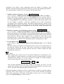
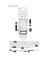
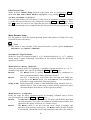
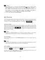
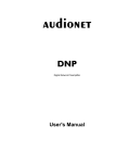
Key assignment MAP 1
MAP 1:
1/9 pages
Mi 14:51
Digital In 1
Digital In 2
Digital In 3
Digital In 4
Digital In 5
Digital In 6
Current
Activity
Devices
1
2
3
4
5
6
7
8
10
9
11
1
Press key Info to activate the Show function. The MAP 1 displays now
information on the current program format as well as output and speaker
configuration. Further details on this function are in sections 'Display' and 'On
Screen Display'. In case the On Screen Display is switched off, the OSD will be
activated automatically while displaying the information after using the Info key.
2
Use key Guide to switch on/off the On Screen Display (OSD) of your MAP 1. This
key has the same function as key OSD of the Harmony One.
Note: The OSD is only available at video outputs Video Out in Cinch Video
format (FBAS 5 ) and S-Video format (S-VIDEO 1 14 ).
15
3
Vol+ , increases the volume of the MAP 1 while in RUN mode. If the MAP 1 is in
one of the setup menus, use Vol+ to select a setup option of the current menu
item. This key has the same function as the key up on the front panel.
4
Ch+ , switches to the next input channel while in RUN mode. If the MAP 1 is in
one of the setup menus, Ch+ goes back to the previous menu item.
5
Vol- , decreases the volume of the MAP 1 while in RUN mode. If the MAP 1 is in
one of the setup menus, use Vol- to select a setup option of the current menu item.
This key has the same function as the key down on the front panel.
6
Ch- , switches to the previous input channel while in RUN mode. If the MAP 1 is
in one of the setup menus, Ch- proceeds the next menu item.
7
Press
to toggle muting. Muting and de-muting is done softly, i.e. volume will
decrease/increase slowly.
8
4 , starts playback. Press this key during playback to pause playback. Press again
to resume from last position.
9
9 , skips back to start of previous track.
10 : , skip forward to start of next track.
11 < , stops playback. Press key 4 to resume playback from the start of current
track.
·
Note:
Use keys 8 to 11 for USB-Audio playback control via digital Audio input 7
USB AUDIO 7 . Please refer to section 'USB Audio'.
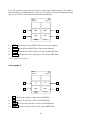
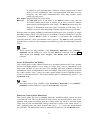
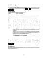
Screen page 1
Use keys on screen page 1 to access one of the first 6 digital audio inputs directly. See
back panel layout to find corresponding input jacks (see section 'Overview of
connections'). You will find keys to further audio inputs on screen page 2.
MAP 1:
Mi 14:51
1/9 pages
1
Digital In 1
Digital In 2
2
3
Digital In 3
Digital In 4
4
5
Digital In 5
Digital In 6
6
Current
Activity
Devices
16
1
Select digital audio input Digital Audio IN 1 12 directly.
2
Select digital audio input Digital Audio IN 2 12 directly.
3
Select digital audio input Digital Audio IN 3 12 directly.
4
Select digital audio input Digital Audio IN 4 12 directly.
5
Select digital audio input Digital Audio IN 5 12 directly.
6
Select digital audio input Digital Audio IN 6 12 directly.
Screen page 2
Use the keys on screen page 2 to select one of the 5 remaining audio inputs of the
MAP 1 directly.
MAP 1:
Mi 14:51
2/9 pages
1
Digital In 7
Ext. 8ch In
2
3
USB Audio In
Analog In 1
4
Analog In 2
5
Current
Activity
Devices
1
Select digital audio input Digital Audio IN 7 12 directly.
2
Select the external 8 channel analog audio input 8-CHANNEL ANALOG IN 10
directly.
3
Select digital audio input USB AUDIO 7 directly.
4
Select analog audio input Analog In LEFT 1 / RIGHT 1 9 directly.
5
Select analog audio input Analog In LEFT 2 / RIGHT 2 9 directly.
17
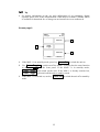
Screen page 3
MAP 1:
Mi 14:51
3/9 pages
1
Dynamic
Range
1
2
EQ
Dolby / DTS
Mode
3
4
PCM Direct
Listening
Mode
5
Current
Activity
Devices
Press key Dyn. Range to enter Dynamic Range menu. Use keys Vol+ and
Vol- to select desired dynamic range:
Maximum:
full dynamic range, no compression at all
Standard:
medium dynamic range, moderate compression
Minimum:
minimal dynamic range, full compression
Note: This menu is only available, if Internal Decoder is set to Multichannel.
2
Press key EQ to switch on/off the double precision parametric digital equalizer.
3
Use key Dolby / DTS Mode to enter Decoder Setup menu. Here you select the
desired mode for Dolby Pro Logic IIx und DTS** Neo:6. Additionally, you choose
between Dolby Pro Logic IIx and DTS Neo:6 processing on stereo PCM signals in
Listening Modes Audionet D8, 3 Stereo or Phantom. For more detailed
description refer to sections 'Setup' and 'Menu Decoder Setup'.
Note: Navigate through the menu using keys Ch+ / Ch- . Change options
with keys Vol- / Vol+ .
4
Use key PCM Direct to switch activate/de-activate PCM Direct mode. If active,
the name of the currently selected input channel in the display is replaced by
---PCM Direct---.
Note: You can only activate PCM Direct mode, if a stereo PCM signal is
available at the current audio input. While in PCM Direct mode, the internal
decoder (and therefore Bass Manager, any matrix surround processing etc.) is deactivated temporarily in order to playback stereo PCM material purely as recorded
and without any changes. To leave PCM Direct mode press PCM Direct again.
If a signal other than stereo PCM is detected at the current input, PCM Direct
mode is switched off automatically. The display informs the user with the message
PCM Direct off. PCM Direct mode cannot be activated if the MAP 1
receives digital data from an Audionet source using the HighBit interface.
18
5
Press key Listening Mode to select the desired Listening Mode. See section
'Listening Mode' for further details.
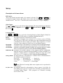
Screen page 4
MAP 1:
Mi 14:51
4/9 pages
1
Front
Center
2
3
Surround
Back
4
5
Sub
LFE
6
Current
Activity
Devices
1
Press key Front to enter the volume setup menu for reference level
(Front Left). Adjust the reference volume level for system level setup using the
keys Vol+ and Vol- .
2
Press key Center to adjust the volume level of the Center channel using keys
Vol+ and Vol- (+12...-18dB).
3
Press key Surround to adjust the volume level of the Surround channels using
keys Vol+ and Vol- (+12...-18dB).
4
Press key Back to adjust the volume level of the Back Surround channels using
keys Vol+ and Vol- (+12...-18dB).
5
Press key Sub to adjust the volume level of the Subwoofer channel using keys
Vol+ and Vol- (+12...-24dB).
6
Press key LFE to adjust the volume level of the LFE channel using the keys
Vol+ and Vol- (+0...-10dB). This function affects only the LFE channel before
it is processed by the Bass Manager.
Use they keys on screen page 4 to adjust the volume levels of all output channels of
your MAP 1. As soon as you press one of the keys, the MAP 1 enters the volume
adjustment menu Level Setup. The level of the left front channel is the reference level
of the whole system. The volume levels of all other channel are adjusted in reference to
it. Therefore, if the left front channel Front Left is selected for adjustment the
volume keys Vol- / Vol+ change the master volume of the system, not just the level
of the left front channel alone.
·
Tip:
In order to adjust all volume levels correctly you should therefore always start with
the left front channel to set the reference level for the whole system, especially if
you are using an SPL meter to adjust volume levels.
19
If this reference level is set correctly, you are able to adjust the volume levels of all
other channels easily. Use key Ch- to skip to the level adjustment of the next channel.
Or use key Ch+ to return to adjusting the previous channel. To change the respective
volume use keys Vol- / Vol+ . Alternatively, you can use the keys 1 to 6 on screen
page 4 to select the channel to be adjusted directly.
By pressing keys Surround or Back the level is adjusted for both channels of the
corresponding channel group Surround or Back. So these keys are mainly used for
changing levels of the Surround or Back channels during listening. You can adjust the
levels of each channel group without changing their stereo balance. In any case you can
always get to the next/previous channel by using the key Ch+ / Ch- .
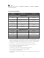
Screen page 5
MAP 1:
Mi 14:51
5/9 pages
1
Digital Rec
Select
Dim Display
2
3
Digital Filter
OSD
4
5
Load Settings
Save Settings
6
Current
Activity
Devices
1
Press key DigiRec Select to decide which signal is routed to the digital outputs.
Use keys Vol- and Vol+ to select digital input is output at the digital output
jacks Digital Audio OUT 13 independently from the current input channel. The
digital signal is always available in both formats coaxial and optical. To switch off
the digital outputs select No Digital In. Choose option Tied to Dig. In
to route the currently selected digital input to the digital outputs respectively.
2
Press key Dim Display , then adjust the display brightness with keys Vol+ and Vol- .
Note: During adjustment the display stays at 100% brightness for better
readability. The new selected brightness will be set after returning to RUN mode
my pressing Dim Display again or just waiting for approx. 12 seconds without
any new command input. If the display brightness is set to Off the display is only
activated while making any adjustment in the setup menus. It will switch off some
seconds after the last change of settings.
20
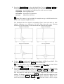
3
Press key Digital Filter to select the digital filter. Use keys Vol- and Vol+ to
choose between 4 different oversampling filters for the front channels Left/Right:
Audionet: special digital oversampling filter with short pre-ringing
Lagrange: short Lagrange filter
Blackman: digital filter by Blackman
Kaiser:
digital filter by Kaiser.
Note: This option is only available for sample rates up to 48 kHz and not for
DVD Audio using the HighBit interface.
You distinguish the four digital oversampling filters from each other by their
impulse responses (see diagrams). Use the filter that suits your listening
preferences. Do not hesitate to experiment with the different filter settings.
4
Use key OSD to switch on/off the On Screen Display (OSD) of your MAP 1. This
key has the same function as key Guide of the Harmony One.
Note: The OSD is only available at video outputs Video Out in Cinch Video
format (FBAS 5 ) and S-Video format (S-VIDEO 1 14 ).
5
Press key Load Setting to re-load previously saved user settings. Select the user
setting you like to load by using the keys Vol- and Vol+ . Press
to load
selected user setting. All current settings will be overwritten during load.
You can choose a name up to 14 characters in length for each of the 30 user
settings. To change a name press key Ch+ . A cursor marks the character to be
changed by pressing Vol- or Vol+ (see also Edit Channel Name). Move
cursor one position to the right by pressing
. While the cursor is active, you get
21
to the names of the other user settings with keys Ch+ and Ch- . To leave edit
mode press Load Setting again.
6
To save the current settings as user setting press key Save Setting , and choose
one of the 30 memory spaces with the Vol- and Vol+ keys. All data at the
corresponding memory location is overwritten by the current settings after pressing
key.
the
You can simply assign the current user setting to only one input channel or even to
all input channels at once. Press Ch+ and select the input channel with Vol- or
Vol+ . Then press
to transfer the current settings to the selected input channel.
Press Ch+ again to enter mode to assign current settings to all input channels.
Press
to start data transfer.
A user setting comprises: Volume and balance levels of all output channels,
PCM Direct mode status, dynamic range, Dolby Pro Logic IIx and DTS Neo:6
mode, Listening Mode and Digital Filter. 30 memory locations for storing user
settings are available. The user can assign a name up to 14 characters in length to
each user setting. Additionally, each of the 12 input channels saves automatically
all current settings independently (channel settings). The 30 memory locations (user
settings) can only be accessed by the user when using the Save Setting
function. So they are independent from the channel settings.
Note: Current master volume, speaker settings, state of internal decoder, video
options etc. are saved automatically and independently when changing a setting
and/or switching off the MAP 1.
Note: After adjusting the volume levels of all output channels we recommend
to save these found settings to all input channels as a simple start up for further
channel or source dependent level settings. To save the current level settings to all
input channels press the following keys:
Save Setting à Ch- à
Now all input channels have the same volume level settings. Of course, you can
change these settings easily for each input channel independently, if necessary.
22
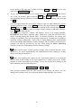
Screen page 6
MAP 1:
Mi 14:51
6/9 pages
1
Channel
Setup
Bass
Manager
2
3
Global Setup
Delay
Manager
4
5
Video Setup
Test Tone
6
Current
Activity
Devices
1
Channel Setup enters the Channel Setup menu.
2
Bass Manager enters the Bass Manager menu.
3
Global Setup enters the Global Setup menu.
4
Delay Manager enters the Delay Manager menu.
5
Video Setup enters the Video Setup menu.
6
Press key TestTone to start the internal test tone generator. The generator
delivers a noise signal to the Front Left channel. You can now adjust the reference
level with keys Vol- / Vol+ as described above. Press key Ch- to produce the
noise signal in the next channel. Or use key Ch+ to skip back to the previous
channel. Ch- moves the noise signal clockwise (according to your speaker
positions in your listening room) from one channel to the other, Ch+ selects the
channels anti clockwise. Adjust the level of each selected channel so that all
channels reproduce the noise signal of the test tone generator with the same volume.
Press TestTone again to switch off the test tone generator and return to RUN
mode.
Note: No test tone is available on the Subwoofer output!
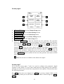
Screen page 7
All 8 keys on screen pages 7 and 8 are used to configure the parametric, digital
equalizer. If the MAP 1 is in any other mode than the setup mode for the equalizer,
pressing one of the 8 keys invokes the setup mode for the equalizer. Then the keys have
the following functions:
Key Ch- selects the next channel, key Ch+ the previous channel. While in the
equalizer setup mode you are still able to adjust the master volume using keys Vol- /
Vol+ .
23
Leave the equalizer setup mode by using one of the other setup menu keys. The MAP 1
then enters the corresponding menu. If you wait for approx. 12 seconds without pressing
any key, the MAP 1 will return to RUN mode automatically.
MAP 1:
Mi 14:51
7/9 pages
1
MPE-
MPE+
2
3
Freq-
Freq+
4
Current
Activity
Devices
1
MPE- selects the previous MPE*) filter of the current channel.
2
MPE+ selects the next MPE filter of the current channel.
3
Freq- decreases the center frequency of the current MPE filter.
4
Freq+ increases the center frequency of the current MPE filter.
*)
MPE = Minimum Phase Equalizer
Screen page 8
MAP 1:
Mi 14:51
8/9 pages
1
Q-
Q+
2
3
Gain-
Gain+
4
Current
Activity
Devices
1
Q- decreases the Q-factor of the current MPE filter.
2
Q+ increases the Q-factor of the current MPE filter.
3
Gain- decreases the gain factor of the current MPE filter.
4
Gain+ increases the gain factor of the current MPE filter.
24
·
Tip:
For further information on the use and configuration of an parametric, digital
equalizer please refer to the documentation of the analyser software CARMA which
is available for download free of charge on our internet site www.audionet.de.
Screen page 9
MAP 1:
Mi 14:51
9/9 pages
2
Power On
1
Power Off
3
Power
Toggle
Current
Activity
Devices
1
If the MAP 1 is in stand-by mode, press key Power On to switch the unit on.
2
Use Power Toggle to switch on/off the MAP 1. This key has the same function
as the key power on the front panel. If the MAP 1 is in stand-by mode,
Power Toggle will switch on the unit. If the MAP 1 is already switched on,
Power Toggle will switch off the unit to stand-by mode.
3
If the MAP 1 is switched on, use key Power Off to switch the unit off to stand-by
mode.
25
Setup
Description of all menu items
RUN mode:
This is the normal operation mode, if no menu is selected. Use Vol- and Vol+ keys
to adjust the master volume. The display shows name and number of the selected input
channel in the 2nd line. The 3rd line shows the current volume (see chapter 'Display').
Select Input:
Use up and down keys to select desired input channel. The input channels are aligned in
the following order: Digital In 1 to 7 12 , USB 7 , External 8ch In 10 and Analog
In 1 and 2 9 .
Listening Mode:
Use Vol- and Vol+ keys to select the Listening Mode for Dolby Digital, Dolby Pro
Logic IIx, DTS decoding or DVD Audio (via Audionet HighBit Interface).
Mono:
all program material is downmixed to mono
Stereo:
reproduces 2-channel source material as 2-ch Stereo, turns off Dolby
Pro Logic IIx or DTS Neo:6 decoding, any other multichannel material
is downmixed to Stereo output (2/0 Lo/Ro). Mono signals are re-routed
from the Center channel to both Front Left and Right channels.
Phantom:
information on the Center channel is re-routed to Front Left and Right channels
3Stereo:
reproduces audio programs using only the three front channels (L,C,R)
Surround: reproduces all channels originally available in the program material, 2-channel
Stereo is reproduced as Stereo (see table 'Overview Listening Modes').
Audionet D8: reproduces all available channels of the program material. Additionally,
material with stereo encoded surround channels is always extended to 7.1
channels. 2-channel Stereo is expanded by Dolby Pro Logic IIx or DTS
Neo:6 to 6.1 or 7.1 channels (see table 'Overview Listening Modes').
Party Mode: all input material is downmixed to 2-channel Stereo and distributed to
all available speakers as follows:
Front Left = Surround Left = Back Left
Front Right = Surround Right = Back Right
Center
= ½ Front Left + ½ Front Right
Note: With this Listening Mode mono signals can be reproduced in
every speaker.
Lt/Rt out: all program material is downmixed to Stereo output (2-ch Lt/Rt) for
later Dolby Pro Logic IIx or DTS Neo:6 decoding (recommended for
recording Dolby Digital / DTS programs on 2-channel recording
devices like VCRs)
26
Note:
This menu is only available, if Internal Decoder is set to Multi-Channel or
DVD Audio playback.
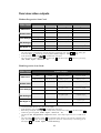
Overview Listening Modes:
Program
Audionet D8
Surround
2-Channel formats
PCM
Dolby Digital 2/0
(not Surround encoded)
Dolby Digital 2/0
(Surround encoded)
DTS 2/0
(not Surround encoded)
DTS 2/0
(Surround encoded)
Dolby Pro Logic IIx 2) or
DTS Neo:6 4)
Stereo PCM
1)
Dolby Digital + Pro Logic IIx 2)
Dolby Digital 2/0
Dolby Digital + Pro Logic IIx 2)
Dolby Digital + Pro Logic IIx 2)
DTS Neo:6 3)
DTS 2/0
DTS Neo:6 3)
DTS Neo:6 3)
Multi channel formats
Dolby Digital
Dolby Digital + Pro Logic IIx 2)
Dolby Digital 5)
DTS
DTS + Neo:6 4)
DTS 5)
Dolby Digital + Pro Logic IIx 2)
Dolby Digital EX 6)
DTS-ES Matrix
DTS-ES Matrix 4)
DTS-ES Matrix 4)
DTS-ES Discrete
DTS-ES Discrete 4)
DTS-ES Discrete 4)
DTS 96/24
DTS 96/24 + D8 7)
DTS 96/24 5)
Dolby Digital
(Dolby Surround EX encoded)
*1)
The decoder mode is defined by the function Convert 2-ch PCM to in menu Decoder Setup (see chapter
'Setup', section 'Decoder Setup'). Additional options are available by function Set Dolby Pro Logic
IIx Mode for 2-Channel or Set DTS Neo:6 Mode (see chapter 'Setup', section 'Decoder Setup').
*2)
The decoder delivers a 7-channel output. The Back Surround speakers playback a stereo signal.
*3)
The decoder delivers a 6-channel output. The Back Surround speakers playback a mono signal each.
*4)
same as 3). Additional options by function Set DTS Neo:6 Mode
(see chapter 'Setup', section 'Decoder Setup').
*5)
The decoder delivers a 5-channel output. The Back Surround speakers playback no signals.
*6)
same as 3). Additional options by function Dolby Digital EX Mode
(see chapter 'Setup', section 'Decoder Setup').
*7)
The decoder delivers a 5-channels output. Additionally, the Back Surround speakers playback the signals of the
Surround speakers.
27
Menu Channel Setup
This menu comprises all settings, that are valid only for the current selected input
channel. If you change the input channel, all settings are saved automatically and the
channel settings for the new channel are loaded. Therefore, you can adjust the MAP 1 to
each connected source independently, and don't have to worry about saving and reloading the settings you made. The MAP 1 will do the work automatically.
Internal Decoder:
In order to switch off the internal decoder, press key Vol- (the display shows pure
2-channnel). All program material is downmixed to 2-ch Stereo independently from
the original program format. Dolby Pro Logic IIx or DTS Neo:6 decoding, bass and
delay management are off in this mode. It is strongly recommended to use this mode for
Stereo PCM or 2-channel analog sources only.
Press key Vol+ to activate the internal decoder (the display shows MultiChannel). All incoming program formats (PCM or bitstream) are detected and
decoded automatically (see also section 'PCM direct').
·
·
·
Note:
The internal decoder can be activated for all audio inputs except the external 8channel analog input (External 8ch).
If the internal decoder is active for a 2-channel analog audio input, the input signals
are internally converted from analog to digital. Now all functions like Dolby Pro
Logic IIx or DTS Neo:6 decoding, bass and delay management, digital equalizer etc
are available as for any digital audio input.
The internal analog to digital converter has an input sensitivity of 2 VRMS. If input
signals exceed this level, the converter will overload causing audible distortions. In
this case, reduce the output level of the unit connected to the MAP 1 until no
overload occurs.
Set Video Input:
You can assign one of the video inputs (2 cinch video inputs 4 , 2 S-Video inputs 15 ,
1 DVI input 3 , 1 alternative YUV/RGB input) to each input channel independently.
Even multiple assignments are allowed (e.g. for connecting a DVD player that uses
more than one audio output). If no video input is needed for an audio input, please
select No Video Input.
No Video Input
Video In1 or In2
S-Video In1 or In2
DVI-Int. In
Cinch Analog
No video input is selected.
The corresponding video input IN1 or IN2 4 is selected.
The corresponding S-Video input S-VIDEO IN1 or
S-VIDEO IN2 15 is selected.
The video input 3 is used for analog and digital DVI
signals (DVI-I) which are routed directly to the DVI
output 16 .
The video inputs 4 and video output 5 are re-defined
in their function to be used for component video input.
28
Their analog signals are routed directly to the analog
part of DVI output 16 .
·
·
·
·
Note:
If you assign any of the Cinch (or Composite) video inputs 4 to an audio input, you
will have a video signal at the Cinch/Composite video output 5 as well as at the
S-Video output 14 (automatically converted by the internal 'Cinch-to-S-Video
Converter').
If the optional Progressive Scan Card is inserted, some more video inputs and
options are available. In this case, please refer to chapter 'Progressive Scan Card'
for more detailed information.
This menu item is located in the menu Channel Setup, as it is a setting, that can be
selected for each input channel independently. Although the menu Video Setup
deals with global video settings, the same function Set Video Input, as described
above, is also integrated into the Video Setup menu, simply for an easier access.
For each audio input the corresponding video input is assigned individually. To
simplify this procedure, select the desired video input for each audio input during
the setup (of channel levels, names, decoder settings etc) for this audio input.
Offset Adjust:
Use Vol- and Vol+ keys to adjust the input channel offset. You can add gain or
attenuate each input channel individually within a range of +9...-9dB in order to
compensate different output levels of sources connected to the MAP 1.
Set Listening Mode:
This menu item has the same function as the key Listening Mode on the remote
control described above.
Digital Filter:
This menu item has the same function as the key Digital Filter on the remote control
described above.
Dynamic Range:
This menu item has the same function as the key Dynamic Range of the remote
control described above.
Set Dual Mono:
Select the preferred playback mode for DVD soundtracks in Dual Mono mode with the
Vol- and Vol+ keys.
CH1+CH2:
Both Dual Mono channels are reproduced
CH1 only::
Only Dual Mono channel 1 is reproduced
CH2 only:
Only Dual Mono channel 2 is reproduced
·
Note:
This menu is only available, if Internal Decoder is set to Multi-Channel.
29
Edit Channel Name:
While in menu Channel Setup proceed to this menu item by pressing key Ch- if
menu item Set Dual Mono Mode is highlighted, or by pressing Ch+ while menu
item Set Decoder is highlighted.
For each input channel you can choose a name up to 14 characters in length. A cursor
(↑) marks the current character to be changed by pressing Vol- and Vol+ keys. Press
key
to move the cursor to the right onto the next character position. At the end of
the character string the cursor jumps back to the first position after pressing the key
.
Menu Decoder Setup
Use this menu to select the desired operating modes and options for Dolby Pro Logic
IIx and DTS Neo:6 decoding.
·
Note:
This menu is only available, if the internal Decoder is active (option Internal
Decoder is set to Multi-channel).
Set Dolby Pro Logic IIx Mode:
Dolby Pro Logic IIx expands original 2- or 5.1-channel material to 6.1- or 7.1-channel
output using a matrix technology. Depending on the original format the following
options are available:
Menu item for Multi-Channel:
Select the preferred mode for expanding 5.1-channel program material to 6.1- or 7.1channels using Dolby Pro Logic IIx by using the Vol- and Vol+ keys:
Movie:
The Movie mode is optimal for 5.1-channel movie soundtracks or
stereo soundtracks that are Dolby Surround encoded.
Music:
Not all 5.1 material may sound ideal when decoded with Dolby Pro
Logic IIx in the Movie mode. Use mode Music if the soundfield is
focused too much on the Back Surround speakers.
Dolby D EX: Dolby Digital EX creates six full-bandwidth output channels from 5.1channel sources. This is done using a matrix decoder that derives three
surround channels from the two in the original recording.
Menu item for 2-Channel:
Dolby Pro Logic IIx offers 4 different modes for decoding 2-channel sources. Select
your preferred mode with the Vol- and Vol+ keys:
Movie:
The Movie mode is for use with stereo TV shows and all Dolby Surround
encoded programs. The result is an enhanced soundfield directionality that
approaches the quality of discrete 5.1-channel sound.
Music:
The Music mode is for use with any stereo music recordings, and
provides a wide and deep sound space. The Music mode includes controls
(CenterWidth, DimensionControl and Panorama), that allow the sound to
30
be tailored to your listening tastes. All three of these controls may be used
alone or in any combination. After you experimented with them on a few
programs, you will easily understand their effect and consider which
setting you may prefer.
Pro Logic: Original Dolby Pro Logic mode.
Matrix: The Matrix mode is the same as the Music mode except, that the
directional enhancement logic is turned off. It may be used to enhance
mono signals by making them seem 'larger'. The Matrix mode may also
find use, if fluctuations from poor stereo reception (of FM radio, TV or
satellite receivers) cause disturbing surround signals from a logic decoder.
Because music recording techniques and listening preferences vary so widely, no single
decoding setting is likely to be adequate for all content. Therefore, Dolby Pro Logic IIx
incorporates a separate Music mode to reproduce a convincing and compelling
surround ambience from conventional stereo sources. The Music mode generally
includes three controls for fine-tuning the soundfield to get the most pleasing or natural
effect.
·
Note:
These options are only available, if the Internal Decoder is set to MultiChannel and the Dolby Pro Logic IIx mode Music is selected. Use key Chwhile menu item Dolby Pro Logic IIx Mode for 2-Channel is
selected:
Center Width (OSD: Cntr Width):
This control allows center channel sounds to be positioned between the Center speaker
and the Left/Right speakers over a range of 8 steps. Step 3 uses a combination of all
three front speakers to give the best vocal imaging and most seamless soundstage
presentation, and is recommended for most recordings. Step 0 places all center sound in
the Center speaker. Step 7 places all center sound equally in the Left/Right speakers,
just as in conventional stereo. The Center Width control is automatically preset to 3 in
the Movie mode.
·
Note:
This menu item is only available, if the Internal Decoder is set to MultiChannel and the Dolby Pro Logic IIx Mode Music is selected.
Dimension Control (OSD: Dimension):
This control allows the user to gradually adjust the soundfield either towards the front
or towards the rear. This can be useful to help achieve the desired balance from all the
speakers with certain recordings, that may contain either too much or too little spatial
effect. Step 0 is the recommended setting, which has no effect on the sound. Steps 1, 2
and 3 gradually move the sound forward, and steps -1, -2, -3 move the sound towards
the surrounds. The Dimension control is automatically preset to 0 in the Movie mode.
31
·
Note:
This menu item is only available, if the Internal Decoder is set to Multi Channel and the Dolby Pro Logic IIx Mode Music is selected.
Panorama:
This control extends the front stereo image to include the surround speakers for an
exciting 'wraparound' effect with side wall imaging. It is particularly effective for
recordings which have strong left or right channel elements in the mix, as these are
detected and accentuated by the Panorama process. The Panorama control is
automatically turned off in Movie mode.
·
Note:
This menu item is only available, if the Internal Decoder is set to MultiChannel and the Dolby Pro Logic IIx Mode Music is selected.
Set Neo:6 Mode (OSD: DTS Neo:6 Mode):
DTS Neo:6 generates a 6-channel soundfield from an original 2-channel source using a
matrix technology. Two user selectable modes are available:
Cinema: The Cinema mode is suitable for matrix encoded stereo source material
(like movie or TV soundtracks).
Music:
Use the Neo:6 mode Music for stereo music material, that did not use any
surround matrix encoding technologies during recording. Neo:6 produces a
soundfield with up to 6 channels, that does not diminish the subtleties and
integrity of the original stereo recording.
Set Neo:6 Option Cgain (OSD: 4CntrGain):
If the DTS Neo:6 mode Music is selected, the user can influence and, by using the
option Cgain, adjust the soundfield to his listening preferences. Cgain changes the
amount of Center signals mixed to the Left and Right channels. The Center channel
level is not influenced by setting Cgain.
The user can adjust Cgain from 0.0 to 0.5 in steps of 0.1. If Cgain = 0.0, the Left
and Right channels are played back unchanged referring to the original stereo mix. The
higher the value of Cgain, the more dominant is the sound of the Center channel.
Menu item Convert 2-Ch PCM to:
Use keys Vol- and Vol+ to select the desired matrix decoder technology to expand
stereo PCM signals to 6 or 7 channels:
Dolby PLIIx: Select this option to use Dolby Pro Logic IIx. The options selected by
function Dolby PL IIx Mode for 2-Ch are used (see above).
DTS Neo:6:
Select this option to use DTS Neo:6. The settings from function DTS
Neo:6 Mode are applied (see above).
32
Menu Global Setup
This menu adjusts global options for the MAP 1, which are saved automatically when
switching off the unit to stand by mode and re-loaded automatically when switching on.
Select the Global Setup menu by pressing key Global Setup .
·
Note:
The first selected menu item of the On Screen Display is always Output Phase
although it is not the top item. The reason is, that the first two items in the menu
both are accessible directly via keys on the remote control. Of course, you can select
both items using the keys Ch+ / Ch- to navigate through the menu.
Output Phase:
Press Vol+ key to invert the phase of all output channels (inverted). Use this
option for CDs, that were recorded with inverted phase. Press Vol- key to set phase
back to normal.
Set Standby-Text:
With this option you can specify how the stand by mode is shown in the display. There
are following possibilities to choose:
Dot:
Please press the Vol- key. The stand by mode is indicated by a little point
in the display.
Off:
Please press the Vol+ key. The stand by mode is indicated by the text off
in the display.
·
Note:
In both cases the display position of the stand by text changes every 12 seconds in a
random pattern to prevent a 'burn in' of the display.
Set AutoStart:
To enable the AutoStart option press Vol+ key (On), to disable press Vol- key
(Off). If the AutoStart option is active, the MAP 1 will start up automatically when
connected to mains. Use this option, if you want to start up the MAP 1 by timer.
Dolby Digital EX Mode:
Use keys Vol- and Vol+ to select, if for Listening Mode Surround, Dolby
Surround EX encoded bitstreams are recognized and played back in Dolby Digital EX
mode automatically, or if they are played back like plain Dolby Digital bitstreams:
auto on:
The 'Dolby Surround EX encoded' flag in the bitstream is recognized
and the playback mode is set to Dolby Digital EX automatically.
never on: The 'Dolby Surround EX encoded' flag in the bitstream is ignored. The
bitstream is decoded in Dolby Digital mode.
33
·
·
Note:
This setting refers to Listening Mode Surround only! For Listening Mode
Audionet D8 all Dolby Digital bitstreams are decoded as Dolby Digital +
Pro Logic IIx independent from the flag 'Dolby surround EX encoded'. The
user settings of function Dolby Pro Logic IIx Mode for MultiChannel apply (see chapter 'Setup', section Menu 'Decoder Setup').
See also table 'Overview Listening Modes'.
Menu Video Setup
This menu adjusts global video options for the MAP 1, which are saved automatically
when switching off the unit to stand by mode and re-loaded automatically when
switching on. Select the Video Setup menu by pressing key Video Setup .
Set Lip Sync Delay:
While using video processors in projectors, progressive scan modules etc. the video
signal may be delayed in reference to the audio signal, so that picture and sound are not
in sync any longer. Use keys Vol- / Vol+ to adjust a delay of the audio output of the
MAP 1 to get picture and sound in sync again. The delay can be adjusted from 0 to 100
msec in steps of 0.5 msec.
·
Note:
Adjusting the Lip Sync delay does not affect the delay settings of each output
channel relative to each other. It is only for synchronising picture and sound.
Set Video Input:
This is the same function as in the Channel Setup menu. It is also integrated here for
easier access.
·
Note:
The video input setting applies to each audio input channel independently! All other
video settings within the Video Setup menu are valid globally.
Set TV System:
For correct conversion from Cinch video to S-Video please select the corresponding TV
System. Press Vol- key for NTSC. Press Vol+ for PAL.
All other items in the Video Setup menu relate to an optional Progressive Scan Card.
Please refer to chapter 'Progressive Scan Card'.
34
Menu Bass Manager
Use items in the Bass Manager menu to match the MAP 1 to the speakers in your
system. Navigate through the menu using keys Ch+ / Ch- , select options with keys
Vol- / Vol+ .
Set Speaker Size:
Speaker settings are adjusted by channel groups:
Front
= Front Left and Right
Center
= Center
Surround
= Surround Left and Right
Back
= Back Left and Right
First, choose the method how the bass of the selected channel group is reproduced:
None:
Small:
Large:
X-Bass:
speaker(s) of this channel group is/are not available.
Bass below the cross over frequency (Cross Over Frequency) is
redirected to subwoofer channel or to any speaker selected as Large, if
no Subwoofer is available. Please use this option for small speakers, that
are not capable of reproducing frequencies below the cross over frequency.
the speaker(s) of this channel group reproduce the full frequency range.
Select this option, if your speakers are able to reproduce bass below the
crossover frequency.
same as Large, but additionally the bass below the cross over frequency
of this channel group is re-routed to the Subwoofer. Use this setting if you
want to drive your speaker in full range, but also create a stronger bass
foundation.
Note: As now the speaker(s) of this channel group and the subwoofer
reproduce the bass of this group, an unwanted bass gain could occur. In
this case switch to setting Large or Small
Note: This option is only available, if a subwoofer is connected and the
option subwoofer set to available.
Set Cross Over Frequency:
Now you have to adjust the cross over frequency (Cross Over Frequency) for the
speakers of the current channel groups. It defines the point of operation of the
corresponding filter of the Bass Manager (see 'Set Speaker Size'). Use keys Vol- and
Vol+ to select the cross over frequency. Navigate through the menu by using keys
Ch+ / Ch- .
Set High Pass Q:
Adjust the Q factor of the current high pass filter. The default setting is 0.71 and should
only be altered by experts.
35
Subwoofer:
If a subwoofer is available in your speaker configuration, press Vol+ key to activate it
(available). If a subwoofer is not available, press Vol- key to deactivate the
subwoofer channel (not available).
·
Note:
You can only switch off the subwoofer, if Front speakers are set to Large and no
channel group is set to X-Bass. Otherwise the display shows Configuration
not allowed if you press Vol- key.
Set Subwoofer Phase:
Select phase of the Subwoofer to normal or inverted.
Important:
The following additional conditions apply to the Bass Manager:
· Channel group Front can not be set to None.
· If Front is set to Small all other channel groups are forced to Small and the
Subwoofer is activated.
· Only if channel group Surround is available (= not None), group Back can
be selected to any other than None.
· If channel group Surround is switched to None, group Back is forced to
None automatically.
· If the Subwoofer is not available and one of the channel groups is set to
X-Bass, the Subwoofer will be activated automatically (set to available).
· If any channel group is set to X-Bass, the Subwoofer cannot be deactivated.
36
Menu Delay Manager
Use this menu to enter the distances from your speakers to your listening position (Set
Speaker Distance). The distance ranges from 0 to 1500 cm in steps of 5cm.
Alternatively, you can enter the distances in inches (see 'Set Distance Unit').
According to the entered distances, the MAP 1 calculates the necessary delays of each
channel to ensure, that all signals from all speakers arrive at the same time at the
listening position.
Use keys Vol- and Vol+ to enter the distance, select channel to be setup with keys
Ch+ / Ch- . The order of channels is the same as in the Level Setup menu.
Subwoofer Distance Offset:
This option 'virtually' moves the subwoofer relative to the listening position (= adjusting
the 'phase' of the subwoofer). Use positive values, if you want to delay the signal from
the subwoofer relative to all other channels. Use negative values, if the signal from the
subwoofer should arrive earlier than the signals from all other speakers.
Set Distance Unit:
To choose the unit for measuring the distances of speakers, use Vol+ to select
Centimeter or Vol- to select Inches. Distances already entered into the system
are converted to the selected unit automatically.
37
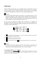
Display
While in RUN mode the 2nd line of the display provides the (user definable) channel
name (14 characters long) followed by the number of the input channel (D1 to D7 for
Digital In 1 to 7, An1 and An2 for Analog In 1 and 2, Ex8 for 8ch External Input, USB
for USB Audio playback).
If the internal decoder is inactive (Internal Decoder set to pure 2-channel),
the volume is displayed in the third line as Stereo Volume –xxdB with xx =
current volume of the current input channel. If the internal decoder is active, the 3rd line
changes to Master Volume –xxdB with xx = current master volume of all
channels. So the user can easily see, if the internal decoder is active or disabled.
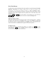
Example:
Channel name
Number of input channel
Digital In 1
è D1
Master Volume -24dB
Status of internal decoder
Volume
If using a digital input, the 1st line of the display will show Receiver Out Of
Lock! while there is no valid digital signal at the current input. If a valid signal is
detected by the digital receiver, the 1st line changes to Receiver locked for a
moment. Is the internal sampling rate converter active, the display shows SRC
active. After that information about program format, output and speaker
configuration follows. Press Info key at any time to force the display to show this
information. After some seconds, the display returns to showing volume information.
Every program format, the current decoding and output format is displayed as the
following:
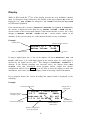
Example:
Current decoder mode
Program format of
the input signal
Sample rate of
input signal
2 Digital + PLIIx Movie
3/2.1
448kbps
48kHz
Audionet D8
EQ: off
L C R LS LB RB RS
SUB
Current listening mode
Bitrate of input
data stream
Speaker configuration
and output format
38
Status of the
digital equalizer
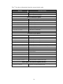
The 1st line shows information about the current decoder mode:
Display
Decoder mode
Test Tone on
Test tone generator is active
2-Channel Analog Input
pure 2-channel analog playback
Stereo PCM input signals
PCM 2-Ch Stereo
2-channel PCM is played back as stereo
PCM A/D converted 2-Ch
analog-to-digital converted stereo signal
2 Pro Logic IIx Movie
Dolby Pro Logic IIx in Movie mode
2 Pro Logic IIx Music
Dolby Pro Logic IIx in Music mode
2 Pro Logic IIx Matrix
Dolby Pro Logic IIx in Matrix mode
2 Pro Logic
Dolby Pro Logic IIx in Pro Logic mode
DTS Neo:6 Cinema
DTS Neo:6 in Cinema mode
DTS Neo:6 Music
DTS Neo:6 in Music mode
Bitstream input signals
2 Digital
Dolby Digital
2 Digital EX
Dolby Digital EX
2 Digital+PLIIx Movie
Dolby Digital with Pro Logic IIx in Movie mode
2 Digital+PLIIx Music
Dolby Digital with Pro Logic IIx in Music mode
2 Digital+PLIIx Mtx
Dolby Digital with Pro Logic IIx in Matrix mode
2 Digital+Pro Logic
Dolby Digital with Pro Logic IIx in Pro Logic mode
2 Digital 2-ch Stereo
Dolby Digital played back as 2-channel stereo signal
DTS Digital Surround
DTS Digital Surround
DTS ES Discrete
DTS-ES Discrete
DTS ES Matrix
DTS-ES Matrix
DTS + Neo:6 Cinema
DTS with Neo:6 in Cinema mode
DTS + Neo:6 Music
DTS with Neo:6 in Music mode
DTS 96/24
DTS 96/24
DTS 96/24 + Audionet D8
DTS 96/24 with Audionet D8
DTS 2-Channel Stereo
DTS played back as 2-channel stereo signal
Input signals via Audionet HighBit interface
Audionet HighBit
MAP 1 receives audio data from Audionet source (e.g. VIP G3 or
ART G2) via Audionet HighBit interface
39
On the left of the 2nd line the program format of the input signal is displayed by:
m/n.x
m = number of front channels
n = number of surround channels
x = 1 → LFE1) is available
= 0 → LFE1) is not available.
While receiving digital input signals, the current sample rate is shown on the left of the
2nd line.
If the input signal is a bitstream (like Dolby Digital or DTS), the current bitrate is
displayed as kbps (kbit per second) in the middle of the 2nd line. In case of a PCM input
signal information about the usage of emphasis during recording is shown instead of
the bitrate:
EMPH
recorded using emphasis
–
no emphasis used.
The 3rd line informs about the current Listening Mode and the status of the digital
equalizer.
The 4th line provides information about the output and speaker configuration. If a
speaker is available in the current speaker configuration, and it is supported by the
current Listening Mode, the corresponding letter is printed in the display:
L
C
R
LS
RS
BL
BR
BC
=
=
=
=
=
=
=
=
Left Front
Center
Right Front
Left Surround
Right Surround
Back Left
Back Right
Back Center2)
If a speaker is used by the program material, the corresponding letter is printed
inversely in the display.
If the subwoofer is active, it is displayed by an inverse SUB. Otherwise this symbol is
not printed.
1)
LFE is the Low Frequency Effects channel in the program material.
2)
if only one speaker is available in the channel group Back
40
·
·
·
·
·
·
Note:
Is the brightness set to Off the display is only on during setup or volume
adjustments. It switches off automatically several seconds after the last user entry.
The MAP1 activates the 'display saver' automatically after 10 minutes without any
user entry.
During active 'display saver', the display shows only the number of the selected
input channel and current volume level (example: An1
-47dB). The display
brightness is always reduced to 25%, and the location of the information text will
change randomly every 12 seconds to prevent any 'burn-in' effect of the display. If
the MAP1 is muted the text mute is displayed instead of the volume level. Error
messages are abridged.
The 'display saver' is de-activated and the display returns to its normal mode as soon
as any user entry is detected
The user cannot switch off the automatic 'display saver' function!
Use the key Info of the remote control at any time to display full information on
the current status
41
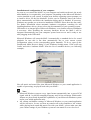
On Screen Display (OSD)
Activate the On Screen Display by pressing the key OSD or Guide on the remote
control. The signal of the OSD is available at the video outputs in Cinch video 5 and
S-Video format 14 and replaces the current video image. Press OSD or Guide
again to switch the On Screen Display off. Now the current video image is back at the
video output.
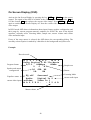
In RUN mode OSD shows information about input format, speaker configuration and
their usage by current program material, emphasis for PCM CDs, state of the digital
equalizer, currently active Listening Mode, sample rate, master volume and current
video and audio input.
If any of the setup menus is selected, the OSD shows the corresponding dialog. The
currently selected option is marked by a black bar in the background and yellow text.
Example:
Decoder mode
Program format
Speaker and output
configuration
Equalizer status
current video input
A U D I O N E T
M A P
Dolby Digital + PL IIx Movie
2/0.0
448kbps
48kHz
L
C
R
LS SUB RS
LB
RB
EQ off
Audio:
Video:
M A S T E
Surround
Digital In 2
Video In 1
R :
- 5 5 d B
Mastervolume
42
Sample rate
Bitrate
Listening Mode
current audio input
Progressive Scan Card
The optional Progressive Scan Card is recognized by the MAP 1 automatically and
needs no special system setup. The configuration of the Progressive Scan Card refers
only to simple adjustments to meet the needs of the video display (video
beamer/projector, plasma TV etc) connected to the MAP 1. The Progressive Scan Card
offers several video inputs that are selectable as easy as the Cinch (Composite) and
S-Video inputs using the Set Video Input function in the Channel Setup or
Video Setup menu. Please find a detailed description in the following.
Using video inputs with installed Progressive Scan Card:
You can connect and use the Video- 4 and S-Video inputs 15 of the MAP 1 with a
Progressive Scan Card installed in the same way as without the card. The video signal
of the currently active video input is fed to and processed by the Progressive Scan Card
internally.
If the Progressive Scan Card is installed, additional video inputs are available. You
select these inputs as usual using function Set Video Input. You get to this
function by entering either the Channel Setup or the Video Setup menu. If you are on
screen page 6 in the device menu MAP 1 of the remote control, press the following keys
to get to the function Set Video Input:
Video Setup à ChOr: Channel Setup à ChNow use keys Vol- and Vol+ to select the desired video input for the currently
active audio input.
·
Note:
To each audio input the user can assign a video input separately. The easiest way to
achieve this, is to assign the video input while you setup the individual settings (like
level adjustments, name assignment, decoder settings etc) for each audio input (see
chapter 'Setup', section 'Menu Channel Setup').
Please consult the user's manual of your video source (DVD player, LD player, VCR
etc), which video format is available at its video outputs and choose a compatible video
input of the MAP 1. The following video inputs are selectable for each audio input
individually, if the Progressive Scan Card is installed:
No Video Input
No video input selected.
Video In1 or In2
The corresponding (composite) video input IN1 or IN2 4 is selected.
S-Video In 1 or In2 The corresponding S-Video input S-VIDEO IN1 or S-VIDEO IN2 15
is selected.
DVI-Int. In
Video input 3 is used for digital and analog DVI video signals
(DVI-Integrated). The signal will not be processed by the
Progressive Scan Card, but directly routed from the DVI input
connector 3 to the DVI output connector 16 . Please use this
43
Cinch Analog
DVI YUV In
DVI RGB In
DVI RGB+sog
Cinch YUV In
Cinch RGB+sog
setting for digital and analog DVI video signals already in the
progressive format.
The video inputs 4 and video output 5 are re-defined in their
function to be used for component video input. Their analog
signals are routed directly to the analog part of DVI output 16 .
Use this setting for interlaced or progressive signals, that
should not be processed by the Progressive Scan Card.
Video input 3 is configured for YUV video signals in interlaced
format (see connection diagram below).
Video input 3 is configured for RGB video signals in interlaced
format. The Sync signals are connected separately as H/V Sync or CSync (see connection diagram below).
Video input 3 is configured for RGB video signals in
interlaced format. The Sync signals are provided on the Green
signal line: sog = Sync On Green (see connection diagram
below).
Video inputs IN1 and IN2 4 and video output FBAS 5 are redefined as component (YUV) analog video input for interlaced
component (YUV) signals (see connection diagram below).
Video inputs IN1 and IN2 4 and video output FBAS 5 are redefined as RGB analog video input for interlaced RGB signals
with sync signals on Green signal line: sog = Sync On Green
(see connection diagram below).
Note:
The Progressive Scan Card will process interlaced video signals only! Use settings
DVI-Int. In or Cinch Analog for signal already in progressive format.
·
Connector pin assignment DVI input 3 :
As follows you can find the assignment of DVI input connector 3 for the different
analog video formats. Use these overview to choose the right cable for connecting your
video device.
Pin assignment of the DVI input connector
DVI input connector
Pin
YUV
RGB + H/V-Sync
RGB + C-Sync
RGB + Sync on Green
Analog Vertical Sync
-
V-Sync
-
-
C1
Analog Red
U
R
R
R
C2
Analog Green
Y
G
G
G + Sync
C3
Analog Blue
V
B
B
B
C4
Analog Horizontal Sync
-
H-Sync
C-Sync
-
8
Signal
Analog video input format
44
·
Note:
Many devices use the SCART connector for RGB video output. If your video source
is equipped with a SCART output connector (e.g. the Audionet DVD player VIP), it
has to be connected as follows:
Pin assignment of the SCART-connector
Signal
SCART Pin
DVI Pin
Red
15
C1
Green
11
C2
Blue
7
C3
C-Sync
19
C4
Connection diagram for YUV or RGB video input using video inputs 4 and output 5 :
16
=
or
V
CB
Y
Y
U
CR
B
G
+Sync
R
from output of video source
Video outputs Progressive Scan Card:
The output signal of the Progressive Scan Card is available at video output 16 . If only
the Progressive Scan Card (and not the DVI Module) is installed, pins 8 and C1 to C4 of
the DVI video connector provide the analog progressive video signal (see chapter 'Pin
assignment DVI output connector ')
45
·
·
Note:
If the optional DVI Module is installed too, the progressive video signal of the
Progressive Scan Card is provided in digital DVI format at the video output
connector 16 .
If the optional DVI Module is installed, the progressive video signals are always
available in digital and analog format at the DVI output connector 16 .
The user can choose between the two output video formats YUV and RGB by menu
setup. The selection adverts always to the analog as well as the digital progressive video
output format. If you are on screen page 6 of the device menu MAP 1 of the remote
control, press keys:
Video Setup à Ch+ à Ch+
to get to function Set Progressive Output. Now use keys Vol- and Vol+ to
select desired video output format:
Y U V
R G B
·
The MAP 1 provides a progressive Component or YUV signal at the DVI
Video output 16 (refer to connection diagram below).
The MAP 1 provides a progressive RGB signal at the DVI Video output
16 .
Note: Before you can use the RGB video output, you have to select the
correct output mode for the Sync signals (please refer to connection
diagram and detailed description below)!
Important:
For the analog RGB video output mode only, it is necessary to select the correct
Sync output mode using function Set Video Out. If you are on screen page 6 of
the device menu MAP 1 of the remote control, press the following keys to enter the
function: Video Setup à Ch+
Now use keys Vol- and Vol+ to select desired option:
C-Sync
H/V-Sync
·
Pin C4 of the DVI output connector 16 provides the C-Sync
(Composite Sync) signal, which is used for RGB video output with a
combined sync signal (C-Sync).
Pin 8 of the DVI output connector 16 provides the V-Sync (Vertical
Sync) signal and pin C4 the H-Sync (Horizontal Sync) signal for RGB
video output with separate sync signals.
Note:
Please consult the user's manual of your video display (projector, video beamer,
plasma TV etc) connected to the MAP 1 to decide which video output format is to
be used!
46
Pin assignment DVI output connector 16 (analog signals):
As follows you can find the assignment of DVI output connector 16 for the different
analog video formats. Use this overview to choose the right cable for connecting your
display device.
Pin assignment of the DVI output connector
DVI output connector
Pin
YUV
RGB + H/V-Sync
RGB + C-Sync
RGB + Sync on Green
Analog Vertical Sync
-
V-Sync
-
-
C1
Analog Red
U
R
R
R
C2
Analog Green
Y
G
G
G + Sync
C3
Analog Blue
V
B
B
B
C4
Analog Horizontal Sync
-
H-Sync
C-Sync
-
8
Signal
Analog video output format
Settings for analog YUV video output:
If your video display has a video input for progressive Component or YUV video
signals, connect the MAP 1 according to the diagram above and make the following
settings (like described above):
Set Progressive Output
Set Sync Out
=
=
Y U V
C-Sync
Settings for analog RGB-video output with C-Sync:
If your video display has a video input for analog progressive RGB video signals with a
C-Sync (= Composite Sync) input, connect the MAP 1 according to the diagram above
and make the following settings (like described above):
Set Progressive Output
Set Sync Out
=
=
R G B
C-Sync
Settings for analog RGB-video output with H/V-Sync:
If your video display has a video input for analog progressive RGB video signals with
separate H-Sync/V-Sync inputs, connect the MAP 1 according to the diagram above and
make the following settings (like described above):
Set Progressive Output
Set Sync Out
47
=
=
R G B
H/V-Sync
Settings for analog RGB-video output with 'Sync on Green':
If your video display supports only RGB video signals with Sync signals on the Green
line ('Sync on Green'), connect the MAP 1 according to the diagram above and make the
following settings (like described above):
Set Progressive Output
Set Sync Out
Important:
For this video output mode it is necessary to set the jumper on the Progressive Scan
PCB to position 'SyncOnGreen' (see diagram below). For all other modes, the
jumper has to be in position 'Syncless Component' (default setting).
Syncless Component
·
R G B
C-Sync
Note:
This video format uses only three lines to connect the MAP 1 to the video display as
the Sync signals are transmitted on the same line as the Green signal ('Sync on
Green').
Sync on Green
·
=
=
3 2 1
Jumper positions:
Pin #1 and #2 connected
= Syncless Component
Pin #2 and #3 connected
= Sync on Green
48
Overview video outputs
Without Progressive Scan Card:
Video Input
Video In1/2
S-Video In1/2
Cinch Analog In
DVI Analog In
DVI Digital In
1)
2)
3)
Video Output
FBAS Out
S-Video Out
DVI Analog Out
DVI Digital Out
FBAS
S-Video
-
-
OSD
OSD
-
-
-
S-Video
-
-
OSD
OSD
-
-
-
- 2)
OSD
equal to input
1)
equal to input
-
3)
-
-
OSD
OSD
-
-
-
-
-
equal to input 3)
OSD
OSD
-
-
The video signal is routed directly from the alternative component video input 4 , 5 to the analog part
of the DVI output 16 without any processing (Set Video Input = Cinch Analog).
In this mode the video output FBAS 5 is re-defined as video input.
The video signal is routed directly from the DVI input 3 to the DVI output 16 without any processing
(Set Video Input = DVI-Int. In).
With Progressive Scan Card:
Video Input
Video In1/2
S-Video In1/2
Cinch Analog In
DVI Analog In
DVI Digital In
1)
2)
3)
4)
5)
Video Output
FBAS Out
S-Video Out
DVI Analog Out 4)
DVI Digital Out 4)
FBAS
S-Video
progressive analog
progressive digital 1)
OSD interlaced
OSD interlaced
OSD progressive
OSD progressive 1)
-
S-Video
progressive analog
progressive digital 1)
OSD interlaced
OSD interlaced
OSD progressive
OSD progressive 1)
-
-
progressive analog
or equal to input 5)
progressive digital 1)
- 2)
OSD interlaced
OSD progressive
OSD progressive 1)
-
-
progressive analog
or equal to input 3)
progressive digital 1)
or equal to input 3)
OSD interlaced
OSD interlaced
OSD progressive
OSD progressive 1)
-
-
-
equal to input 3)
OSD interlaced
OSD interlaced
OSD progressive
OSD progressive 1)
with installed DVI Module only; otherwise no output!
In this mode the video output FBAS 5 is re-defined as video input.
Both analog and digital video signals are routed directly from the DVI input 3 to the DVI output 16
without any processing (Set Video Input = DVI-Int. In).
The function Set Progressive Output determines, if the output signal uses YUV or RGB colour
space.
The video inputs 4 and video output 5 are re-defined in their function to be used for component video
input. Their analog signals in interlaced or progressive format are routed directly to the analog part of
DVI output 16 (Set Video Input = Cinch Analog).
49
USB Audio
With the USB Audio interface you can playback music and sound files from your
computer using the MAP 1 instead of the soundcard of the PC. The MAP 1 is integrated
into your computer system as USB Audio device. The installation is done (mostly)
automatically via Plug'n'Play, provided a correctly installed operating system.
·
Note:
To use the USB Audio functions of the MAP 1, your computer requires to have
Microsoft™ Windows™ 98SE, Windows ME™, Windows 2000 Professional or
Windows XP™ Home/Professional with the latest USB Audio drivers installed. For
further information about the minimum system requirements please refer to the
documentation of your Microsoft Windows version in use.
In case you have Microsoft Windows 2000 Professional or Windows XP
Home/Professional installed on your computer you can use the remote control SRC of
the MAP 1 to control your application software playing back your sound and music files
(usually the Windows Media Player).
1
2
3
4
1
4 , starts playback. During playback, press key to pause playback. Press again to
resume playback at current position.
2
9 , skips back to start of previous track.
3
: , skips forward to start of next track.
4
< , stops playback. Press key 4 to resume playback from start of current track.
·
Note:
In order to control your application with the remote control of the MAP 1, the
program has to be running and its window active. For further information on how to
start and work with your application please refer to its user's manual.
Connecting the MAP 1 to your computer:
Connect digital input 8 USB Audio 7 with a suitable USB cable (plug type A to plug
type B) to a free USB port at your computer that is compatible to USB 1.1 or above and
supports the Full Speed USB protocol.
50
Installation and configuration of your computer:
As soon as you connect the MAP 1 to your computer and switch on the unit, the newly
added hardware is recognized by your computer. Depending on the Microsoft Windows
version installed on your system, it might occur that the operating system prompts you
to install a driver for the new hardware. In this case let Windows choose the correct
driver automatically and follow the installation dialog until its finished. If necessary,
Windows may prompt you to insert its installation CD/DVD. Please have the disc ready.
For further information about automatic hardware recognition, searching for and
installing hardware drivers, please refer to the documentation of your operating system.
USB Audio is an integral part of Microsoft Windows, so no further software installation
is necessary. After installing the necessary hardware drivers the MAP 1 will be
integrated automatically into your computer system from now on and is ready to use
after plugging in the USB cable.
Microsoft Windows will setup the MAP 1 automatically as standard device for sound
playback. In case this is not done automatically due to your current system
configuration, please set the corresponding option manually. To do so, open up the
'Sounds and Audio Devices' dialog of your Windows Settings menu. Click on the tag
'Audio' and select 'Audionet MAP1' from the list of standard devices (see following
example):
Now all music and sound files, that Microsoft Windows or your sound application is
capable of processing, are played back with your MAP 1.
·
·
Note:
Microsoft Windows converts every input format automatically into a stereo PCM
signal with 44.1 or 48 kHz sampling frequency and 16 bits resolution. Which audio
formats are played back depends the capabilities of your Microsoft Windows system
and/or your sound application only.
All volume and balance settings of Microsoft Windows or your sound application
will be still active. In case you hear no sound at all or the sound has a low volume
while playing back sound and music files with your MAP 1, please make sure that
your volume settings of your Windows system are not muted or set to a low level.
51
·
·
·
The USB Audio input of the MAP 1 is a fully-fledged digital input like all other
inputs. Therefore, you can use all features of the MAP 1 with the USB Audio input,
too, that apply to stereo PCM signals like Dolby Pro Logic IIx or DTS Neo:6. Also,
the parametric digital equalizer is available as well as bass and delay management.
If the USB Audio connection from your computer to the MAP 1 is interrupted, the
MAP 1 will issue the warning Receiver Out Of Lock!. When the connection
is established again, the MAP 1 will prompt the same messages as with all other
digital inputs (see chapter 'Display').
In case you would like to check, if Microsoft Windows recognized your MAP 1
correctly, please open up the Device Manager of your Windows system. You will
find the MAP 1 in the following 3 places in the list of devices:
Sound, video and game controllers →
Human Interface Devices
→
Universal Serial Bus controllers
→
USB Audio Device
USB Human Interface Device
USB Composite Device.
The diagram on the following page gives an overview of an example list of entries in
the Device Manager.
52
Example entries in Device Manager:
53
Security advice
· Avoid packaging material, especially plastic bags, to come into
children’s hands.
· Store and operate the unit in a dry room at a reasonable room
temperature
· Avoid moisture or any liquid to get into the unit
· Set up the unit in a sufficiently ventilated place
· Do not cover, e.g. with a blanket
· Do not open the case. Unauthorised opening will cause loss of
guarantee.
· Use a dry cloth for cleaning
We would like to wish you many exciting listening experiences with your new Audionet
product!
If you still have any questions, don't hesitate to ask your competent Audionet dealer.
54
*
Manufactured under license from Dolby Laboratories. "Dolby", "Pro Logic",
"Surround EX", and the double-D symbol are trademarks of Dolby Laboratories.
**
Manufactured under license from Digital Theater Systems, Inc. U.S. Pat. No's.
5,451,942; 5,956,674; 5,974,380; 5,978,762; 6,226,616; 6,487,535 and other U.S.
and world-wide patents issued and pending. "DTS", "DTS-ES", "Neo:6", and "DTS
96/24" are trademarks of Digital Theater Systems, Inc. Copyright 1996, 2003
Digital Theater Systems, Inc. All Rights Reserved.
Microsoft, Windows, Windows Me, Windows XP, Windows Vista, Windows 7 are
trademarks of Microsoft Corporation. All trademarks are the property of their
respective owners.
Errors and omissions excepted. Specifications and design are subject to changes without prior notice.
audionet is a trademark of Idektron GmbH & Co KG
Engineered and produced by:
Idektron GmbH & Co. KG, Herner Str. 299, Gebäude 6, 44809 Bochum, Germany
www.audionet.de
[email protected]
55