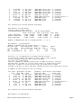
1
London Metropolitan University
Masters in Architecture, Energy and Sustainability
European Masters in the Integration of Renewable
Energies into Buildings
Module AR52P
ESP-r
Luisa Brotas, Arch PhD ARB RIBA
ESP-r course notes (version 11.7)
1/62
Table of Contents
...............................................................................................................................................2
1 STRUCTURE OF THE COURSE....................................................................................... 3
2 INTRODUCTION.................................................................................................................4
3 STRUCTURE OF THE PROGRAM.................................................................................... 4
4 GETTING STARTED.......................................................................................................... 6
5 MODEL GEOMETRY..........................................................................................................9
5.1 Add a window to a surface......................................................................................... 12
6 CONSTRUCTIONS...........................................................................................................15
7 OPERATION..................................................................................................................... 17
8 SIMULATION integrated run.............................................................................................21
9 RESULT ANALYSIS graphs............................................................................................. 22
10 DATABASE MODIFICATIONS....................................................................................... 22
11 A SIMPLE HEATING/COOLING CONTROL.................................................................. 24
12 SIMULATION interactive run.......................................................................................... 27
13 RESULTS text mode.......................................................................................................28
14 AIR FLOW NETWORK................................................................................................... 28
14.1. Natural Ventilated Zone - Control for air flow network by opening the windows....36
15 RESULTS........................................................................................................................39
15.1 Text description....................................................................................................... 39
15.2 Graphs..................................................................................................................... 39
16 Bibliography.................................................................................................................... 42
ANNEX 1 Materials database.............................................................................................. 43
ANNEX 2 Constructions database.......................................................................................46
ANNEX 3 Configuration file..................................................................................................53
ANNEX 4 Results - Hours above a certain value............................................................... 56
ANNEX 5 Results - Energy Consumption............................................................................57
ANNEX 6 Results - Wind data............................................................................................. 59
ANNEX 7 Control file............................................................................................................60
ESP-r course notes (version 11.7)
2/62
1 STRUCTURE OF THE COURSE
1st Day
Objectives: become familiar with the Project Manager and create the
mandatory files to perform a simulation.
The following tasks will be carried out:
•
Geometrical definition of two zones (a 2 storey flat);
•
Definition (selection of defaults) of constructions for the surfaces defined;
•
Connection of the surfaces if in contact to a zone other than the exterior;
•
Creation of a window within a wall and attribution of transparent material;
•
Creation of internal gains as occupants and/or lighting and equipment including
operation schedules;
•
Creation of an infiltration and/or ventilation system (user defined air changes) and its
operation schedules;
•
Use of the simulator module;
•
Use of the results analysis module.
2nd day
Objectives: development of skills by testing optional modules.
The tasks to be carried out:
•
Creation of a multi-layer construction to be used instead of the default;
•
Creation of a simple heating and/or cooling system.
•
Result analysis of energy demand.
3rd day
objectives: study of an air flow network on a naturally ventilated model.
The tasks to be carried out:
•
Definition of nodes, components and connections of the flow network;
•
Definition of a control for the air flow simulating the opening of the windows;
•
Generation, analysis and storage of results.
ESP-r course notes (version 11.7)
3/62
2 INTRODUCTION
ESP-r is a transient energy simulation program that allows modelling the energy and fluid
flows within a combined building and plant system. Since it is one of the most powerful
dynamic thermal simulation tools, its operation is non-trivial. However ESP-r is one of the
best validated packages of its kind, so the results very accurately reflect the real building
environment, provided the input is well defined.
The aim of this 3 days course is to provide you with a basic knowledge of the ESP-r
software to perform a building energy analysis. In order to use the software professionally,
further studies will be necessary.
Before attempting to start working with the program you need to define your objectives and
criteria, as well as the expected results.
There are several rules that should be followed:
•
Spend some time and think what you are trying to do before initiating with the software;
•
Plan in advance what you expect to achieve and what is the best model or tool to reach
your aims;
•
Try to simplify the input of the project. This means a careful choice should be made to
the definition of the model. The more complex the input the likelihood the chances of
errors for beginners and time consuming that with probably add no significant changes
in the results;
•
Test first on a small scale before aiming at bigger or complex situations. Sometimes a
simple analysis might prevent time spending on a solution that does not obtain
significant results;
•
Assign plenty of time to analyse the results and draw your conclusions.
3 STRUCTURE OF THE PROGRAM
ESP-r can be divided into three distinctive parts. The first one is concerned with the
establishment of a valid data model (description of the building and/or plant configuration)
for the simulation. The second part is related to the simulation processing. The third one
with the results recovery and analysis. All the parts are accessed via a Project
Manager. This interface also provides access to other program software and support
applications such as RADIANCE modules, tutorials, databases or export facilities of the
results.
ESP-r is structured in different modules. As soon as you start the program the software
will create an unique folder or a a set of folders and descriptive files to be accessed later
in the program. Table 1 shows the default structure for a fictitious project 'duplex'.
ESP-r course notes (version 11.7)
4/62
Table 1 Folders structure
folders
type
duplex
project folder
duplex/cfg
system files
duplex/ctl
control files
duplex/zones
zone files
duplex/nets
networks
duplex/doc
reports and notes
duplex/temp
odds+ends
duplex/dbs
project databases
ESP-r will also apply different file types with extensions and redirect them to the defined
folders. See Table 2.
Table 2 Filename convention
File type
Extension
System Configuration
.cfg
System control
.ctl
Geometry
.geo
Construction
.con
Operations
.opr
Shading/Insolation
.shd
View factors
.vwf
Air flows
.air
Convention Coefficients
.hcf
Site obstructions
.obs
Mass Flow Network
.mfn
Transparent
Constructions
.tmc
Casual Gains Control
.cgc
.con
ESP-r also includes databases which are essential for the simulation (primitive and
composite constructions, event profiles, plant components and climatic collections).
Depending on the installation they are usually on the following directories and folders:
*prm /usr/esru/esp-r/databases/constr.db1
*mlc /usr/esru/esp-r/databases/multicon.db1
*opt /usr/esru/esp-r/databases/optics.db1
ESP-r course notes (version 11.7)
5/62
*prs /usr/esru/esp-r/databases/pressc.db1
*evn /usr/esru/esp-r/databases/profiles.db1
*clm /usr/esru/esp-r/climate/clm67
*pdb /usr/esru/esp-r/databases/plantc.db1
These databases can be accessed and viewed through the Project Manager but
depending on the users permissions, they can be modified if copied to a different directory.
A good example of use of these databases are the primitives (materials) and
multiconstruction (layered construction) databases that can be accessed to select typical
materials and construction systems for the building envelope.
To perform a simulation with ESP-r, the following file types may be produced:
•
A mandatory geometry, construction, and operation file for each zone;
•
A mandatory system configuration file and an optional configuration control file;
•
An optional air flow, casual gains, shading/insulation, view factors, surface
convection and transparent multi-layered construction file for some or all zones;
•
An optional fluid flow network description file, a pressure coefficients file;
•
Fluid flow results and simulation results files.
1 NOTES
All data in ESP-r are expressed in SI units.
•
The question mark sign '?' provides a tutorial (help) on the options asked. The letter
'd' presents the defaults values;
•
There is no undo button.
4 GETTING STARTED
Log on a computer and type
esp-r
on the command line. This will start ESP-r in its default graphic mode. See Fig. 1.
Figure 1: Entry Level of the Project Manager
ESP-r course notes (version 11.7)
6/62
If you are starting a new file, at the Project management select the menu option e
create new.
Figure 2: Menu create a new project
You will be asked to define a name (ex. ac) followed by a choice of a single or standard
set of folders where the descriptive and results files will be forward to. See fig. 3. As your
model is relatively simple you can select a single directory. For a multiple structure please
refer to table 1.
Figure 3: Windows defining root name and directory structure (single folder)
As default, the root name will be used for the following files created with the appropriated
extension. Do provide a simple description of the project to remember on a later occasion,
see fig. 4
Figure 4: model description
A file called ac.log will be created, you may want to use it as your “note book”. Other
questions will be asked, see fig. 5, as well as general parameters related to the building as
site latitude (degrees positive north of equator) and longitude difference (degrees positive
east of the time meridian of the place).
Figure 5: Question with the association of
images
Examples of longitude difference are -4.1 for Glasgow relative to Greenwich and +2 for NY
relative to 75° standard meridian without daylight savings. However, they can be changed
ESP-r course notes (version 11.7)
7/62
later as well parameters such as ground reflectance and site exposure. See
Management > m browse/edit/simulate > b model context in Fig. 6.
Model
Figure 6: Model context menu
By this step the program has already created the folder structure and at least the
configuration file. Exit the Model management by selecting -exit Project
manager. You will be asked to save your data before you exit if you haven't done so
before. When you launch the model again you can select the model you are working with
its ac.cfg file. On the command line change to the directory created by the software and
subdirectory cfg as:
cd ac (single directory) or cd ac/cfg (structured) .
Now relaunch the software with the indication of the system configuration file as:
esp-r -file ac.cfg
For a memory stick mounted at /mnt/sda1 for a “ac” project with a configuration file
named “ac.cfg” do:
cd /mnt/sda1/ac
esp-r -file ac.cfg
In the initial Model management (see fig. 1) select
m browse/edit/simulate to carry on with setting up the model.
the
menu
option
The following frame Browse/Edit/Simulate will be the main access point to the
selection of the menus such as zones (model geometry and constructions definition),
networks and controls. It will also be the interface for actions such as the
simulation run and the result analysis.
ESP-r course notes (version 11.7)
8/62
5 MODEL GEOMETRY (mandatory)
NOTES
•
Try to reduce the number of zones to a minimum. Avoid detailed definitions;
•
The coordinate system X Y Z refers to the east, north and up directions respectively;
•
It is easier to create the geometry of the zones on a regular grid orientated to the axis.
Later individual zones or the whole model can be rotated and transformed to the real
position;
•
The position of the zones in regards to the origin have no importance if no shading
analysis is to be made because the program recognises the interconnections between
the spaces irrespective to its origin positioning. This means that all the zones can be
located at origin as long as they are well orientated.
•
In order to facilitate future recognition of a specific zone try to be consistent in the
names attributed to the zones, e.g. zones on the 1st floor could be named z11, z12, ...
on the second floor z21, z22 and so one. Names should be maximum 12 characters
long and without spaces and commas.
The next step should be to create the geometry of the zones defining the model. See
Fig. 7.
Figure 7: Model frame of geometry
Select
Model
Management>
m browse/
Browse/Edit/Simulate>
c composition>>
a geometry and attribution
edit/
Zones
simulate
>>
Composition>
>> Zone geometry and attrib
Figure 8: new zone input options
ESP-r course notes (version 11.7)
9/62
After defining a name (maximum 12 characters without blanks) and a short description of
the zone (64 characters), you may create the geometry with input dimensions, load
existing Esp-r or CAD. as in figure 8, and a base geometry as in fig. 9.
Figure 9: zone geometry options
HELP
You have the option to describe zone geometry as an extruded rectangle, a floor plan
extrusion or a general polyhedra. Keeping the geometry as simple as possible will
simplify the constructional attribution and result interpretation tasks.
Points from a bitmap:
Zone geometry can be defined by taking points from a scanned image of a site plan or
floor plan.
To do this you need to scan the relevant source and then convert it to an XBM (X11
monochrome bitmap) file, which should be placed in the project `cfg` folder.
Please ensure that the bitmap is large enough to allow for accurate positioning of the
mouse. The bitmap can be larger than the graphic display area, and where it is you can
pan left/right and up/down.
The source image should have indications on it of an origin (typically X=0.0 Y=0.0), the
North direction and a line of known length (to get scaling from).
Four options are then presented after the selection of the input dimension :
•
rectangular plan – define the coordinates of the origin; the prism width, depth and
height. Assuming the prism is orthogonal to the coordinated system width, depth and
height are the length of the vector in the X, Y and Z axis respectively. The orientation of
the prism may be corrected by the rotation angle measure in degrees anticlockwise
from the X axis, see fig. 10.
•
polygon plan – define the elevation of the base, the elevation of the top and number of
walls (excluding the base and top). The coordinates of the base vertex are defined in
the X and Y axis (input the coordinates around the base polygon anti-clockwise looking
from the top, preferably beginning from the lower left corner of the enclosure). The
extrusion rotation is the angle between the site Y-axis and north for the prism assuming
anticlockwise as a positive rotation. Note this is different from the box orientation
associated with the extruded rectangle.
•
General 3D – define a set of vertices and then link them together to form surfaces
(linked anticlockwise from the lower left when viewing the outside of the surface). You
will be prompted for an origin point and a 2m x 2m floor surface will be placed there.
ESP-r course notes (version 11.7)
10/62
From this initial surface, modify the existing vertices to create the zone enclosure;
•
bitmap – define the points of the zone by clicking on a image. The plan of the model
should have been scanned and saved in a XBM file format and kept on the cfg folder
of the project.
Figure 10: input dimension of zone
After creating your first zone the wireframe similar to the one in fig. 11 should appear on
the screen.
Figure 11: zone z0 wireframe
Although the program saves the definitions created it is a good approach to save the
model regularly. In this menu save by selecting Zone '1' Geometry> > save
To create the second zone select - exit this menu to return to the menu one level
above Zone Geometry/Attribution and * add/delete/copy.
If you decide to add a new zone follow the procedure previous explained.
If you decide to copy and existing zone after giving a new name you will be asked to
transform and/or rotate the new zone. You may want to wait a little until the model includes
further details, such as windows or composition of surfaces, before copying it.
If you decide to delete a zone select the zone in question and answer the questions listed
fig. 12.
As at this point no controls have been defined yet.
Figure 12: delete zone links and update configuration file
ESP-r course notes (version 11.7)
11/62
As you might have noticed the program creates default surface names for the zone
enclosure. The rule is the first vertical surface anticlockwise from origin is Wall-1. Wall-2, 3
and 4 are the following walls in a anticlockwise direction. The top horizontal plane is Top-5
and the ground floor Base-6. To change these to names which are more easily recognised
go
under
Model
Management>
m browse/edit/simulate>>
Browse/Edit/Simulate >
c composition>> Zones Composition> a
geometry & attribution>> Zone Geometry/Attribution and select a zone. In
the menu Zone '1' Geometry select f surface attributes >> Surfaces in
z0> a Wall-1. Under the menu Surface Attributes > a surface name change
the name (e.g. z0_ext_s as surface in zone z0, being exterior and facing south). Do the
same for the remaining surfaces. See fig. 13.
In this menu you may also define the construction of this surface by selecting
e construction which takes you to the Composite menu of the database, and
f environment which takes to the surface boundary of the surface.
In the menu Surfaces in z0 you may * attribute many surface attributions,
namely composition and boundary condition. For more details on these attributes see
section 6. Don't forget to save under Zone 1 Geometry > save to update the '*.geo'
file.
Figure 13: zone z0 surface naming and attributes. Note zo_cei_z1 (zone 0 ceiling connecting to zone
1) stil has the boundary condition unknown as the second zone hasn't been created yet.
5.1 Add a window to a surface
Windows and doors are defined within the surface as a 'hole' to be linked to a vertex of
the surface.
Go
to
Model
Management>
m browse/edit/simulate
>>
Browse/Edit/Simulate
>
c composition>>
Zones
Composition>
a geometry & attribution>> Zone Geometry/Attribution > (select a
zone)>> Zone 1 Geometry> f surface attributes>> Surfaces in z0>
(select surface)>> Surface Attributes> + add glazing/door/opening
See fig. 14.
ESP-r course notes (version 11.7)
12/62
Figure 14: opening geometry menu and options
If insertion is within the surface you will be prompted for an X Z offset from the lower
corner (when viewed from the outside), a width and height. The opening width and height
are in metres. See fig. 15.
Figure 15: coordinates of the window surface
If insertion is at base of the surface you will be asked for a X offset from the left lower
corner of the surface when viewed from the outside, a width and a height.
If the insertion is a percentage of parent surface the opening will be a percentage
of the surface and will be positioned at the centre of the surface.
Before confirming the position, check if the position is ok on the wireframe scheme.
See fig. 16. Deleting a window can be a demanding task involving deleting the window
surface, the associated vertexes of the parent surface description and the deletion of
these vertexes as coordinates.
ESP-r course notes (version 11.7)
13/62
Figure 16: positioning of the window
When prompted for a name try to follow a similar approach to the previous definitions (e.g.
z0_win_s).
You will be asked to select a construction for the inserted surface from the database. See
fig. 17.
Figure 17: window construction material
A warning window appears as a reminder of the modifications occurred to the geometry of
the zone.
Repeat the process for the following windows.
If a surface has more than one window the bounding surface will be revised to flow around
the new 'hole'. You will be asked to provide the corner (left or right) to which link the new
'hole'. If the first `hole` is linked to the lower left corner of the bounding surface, the new
surface might link to the lower right corner. This convention will hopefully limit the chance
of the edges crossing. Also you will need to list the corner node number. See fig. 18.
Figure 18: opening geometry menu and options
Don't forget to >save the modifications to update the '*.geo' file and the '*.con' and/or
'*.tmc' files. When exit the zone the program will apply for the changes and will create the
new files.
ESP-r course notes (version 11.7)
14/62
NOTE
A maximum of 3 windows can be added to a surface to prevent the it from being too
complex. If the position of several windows aren't too significant create a reduced
number with the same area. If more than 3 windows are required divide the surface into
as many surfaces as needed.
6 CONSTRUCTIONS (mandatory)
After having defined the zone geometry you need to attribute physical proprieties and
surface boundaries. Define the composition of surfaces (construction of the wall – select
one from the default database, see annex 1 and 2), the type of surface (opaque,
transparent – the selection will be made as default with the construction defined ) and the
environment (exterior, dynamic boundary, surface in another zone, ground adiabatic, ...)
condition.
The surface constructions can be defined under the menu Model Management>
m browse/edit/simulate>> Browse/Edit/Simulate > c composition>>
Zones
Composition>
a geometry
&
attribution>>
Zone
Geometry/Attribution > (select a zone)>> Zone 1 Geometry>
f surface attributes>> Surfaces in z0> (select surface)>> Surface
Attributes> e construction by selecting a composite pre-defined in the
construction database. See fig. 19.
Figure 19: thermo-physical properties od surfaces
However, to create the '*.con' file for the zone, the constructions should be accessed (at
least
once)
under
Model
Management>
m browse/edit/simulate>>
Browse/Edit/Simulate
>
c composition>>
Zones
Composition>
b construction materials>> Zone constructions and selecting a zone. See
fig. 20.
ESP-r course notes (version 11.7)
15/62
Figure 20: Mandatory construction file
You will be prompted for the name of the zone construction file. By default a path with the
zone name plus '.con' extension will be suggested. If not found, create new file
using this name. The program also checks if the transparent constructions are up to
date.
One by one the composition of surfaces of the zone will be asked. Select from the
database provided and -exit to carry on for the following surface construction.
When selecting a surface in another zone you will be prompted to select the other zone
and the surface within it to be connected to. If the other side was previous defined as other
type of environment you will be asked to update the other side. Although the environment
on the other side has changed you will have to go to that surface attribute and change the
construction.
Construction layers are defined from the outside to inside order. So when selecting
constructions that vary when viewed from one side or the other (e.g. a ceiling) make sure
that on the other side of the surface the construction is inverted.
If you already have a construction file you might want to continue with it. Save the
Composition of 'z0' > save construction details to update the '*.con' and
'*.tmc' construction files. Confirm any update attributes associated with zone geometry to
reflect recent changes.
The Topology Checker allows to define, update or check the connections and
boundaries of the surfaces defined. Run this module to define the surface boundaries or to
correct inconsistencies in surface boundaries.
Go Model Management>
m browse/edit/simulate>>
Browse/Edit/Simulate>>
c composition>>
Zones Composition > d surface connections & boundary>> S
Select Yes from menu options c to i'.
Run form the same menu p edit individual connections or r check via
vertex contiguity or to check all or some contiguities.
Update the surface connections file and accept the default name ac.cnn. Select the zones
to be checked from the menu. One by one all the surfaces, according to our previous
selection, will be checked. When an inconsistency is found you will be asked to define the
boundary. Also when no geometric match is found, e.g. External surfaces, you will be
asked to confirm the type.
Save the new topology and exit the Surface Connections & Boundary.
In the Model Management or ithe Browse/Edit/Simulate menu confirm the update
of the new configuration to the system file ac.cfg
ESP-r course notes (version 11.7)
16/62
7 OPERATION (mandatory)
This module deals with the internal gains inside a zone. These can be occupants, lights or
equipment. It provides schedules for the different casual gains on weekdays, saturday and
sunday periods on hourly intervals.
This module also deals with air flows, infiltration and/or ventilation rates on the basis of
ACH (air changes per hour) or cubic meters per second defined by the user. It provides
schedules for both infiltration and ventilation on similar scheme to the ones defined for the
casual gains. Also it allows the air flow to be thermostatically controlled with 3 set points.
When you select the operations menu for the first time (operations undefined) you may
provide initial casual gain period start times. That applies for each day type (weekday,
saturday and sunday) and for each casual gain type (occupancy, lights and small power).
You still have to define the potency correspondent to the previously defined periods.
Alternatively ignore the period start times and insert manually periods, gains and fraction
distribution.
NOTE
Air flows are defined via one or more sequential periods, the magnitude at a given time
being the flow specified a period that includes that time.
In cases where ventilation will occur with more than one modelled zone then a fluid flow
network or temporal definition file should be employed.
Note that large changes in flow rates between periods can result in unacceptable
interpolation errors.
The add/delete/copy/import option are as follows:
add - adds a period to one or all day types. BE SURE to read the extended help
messages in this dialogue to understand how to use the add function to insert a period
into a profile.
delete - deletes one or more periods (within a list of all periods in all days).
copy - copies Weekdays to Saturdays or Weekdays ->
Sundays
import - copies infiltration, ventilation and control
another zone.
Sundays or Saturdays ->
(or a subset of these data) from
When importing you can specify whether to:
a) preserve the ac/h being imported, e.g. 1.5 ac/h in the source zone is 1.5 ac/h in the
destination zone;
b) preserve the volume of air implied by the ac/h in the source zone, e.g. 1.5 ac/h in a
50m^3 source zone becomes 1.07 ac/h in a 70m^3 destination zone.
To define the operations related to the internal gains and airflow of a zone, select Model
Management>
m browse/edit/simulate>>
Browse/Edit/Simulate>
c
ESP-r course notes (version 11.7)
17/62
composition> Zones Composition> c
Operations Selection> (select a zone)
operational
details>
Zone
If the file *.opr is still not found. See fig. 21.
Figure 21: Operations file
NOTE
New operations for this zone. Please check your notes and provide initial casual gain
period start times for each day type (Weekday, Saturday, Sunday etc.) and for each
casual gain type (occupants, lighting and small power). Do not include periods to be
imported from events profiles.
Example of a schedule including 6 periods:
|
________
Watts |
|
|
|___
___|
|____
| | schedule
|
|___|____..____________|_______
0 7 10..
13 14 18
24
Time
The default assumption is that there is one period (from 0h00 to 24h00) with zero
sensible and latent gains for each casual gain type on each day type.
This ensures that nothing is happening in the zone until you provide relevant information
(e.g. insert at least one period and define a casual gain).
You will be required to define the casual gains (occupancy, lights and small power) for
each day type (weekday, saturday and sunday), their periods of activity and starting times.
Correspondent gains will be defined for each period. Select for day type weekday the
number of casual gain periods for each gain type and each starting times.
See fig. 22. Repeat the process for day types Saturday and Sunday.
The default assumption is that there is one period (from 0:00 to 24:00) with zero sensible
and latent gains for each casual gain type on each day type.
ESP-r course notes (version 11.7)
18/62
Figure 22: Operations file start times and periods
For each day type add a period and define the respective gain in terms of sensible and
latent gain and the radiative and convective fractions. See fig. 23 for occupancy gains.
Figure 23: Occupancy gains
Consider the following internal gains:
•
Occupancy: 2 occupants on the weekday period from 9 till 18, on a sedentary activity
– seated light work - as 110 Wperson-1 of sensible gain and 30 Wperson-1 of latent
gain with a 0.5 radiant and 0.5 convective fraction.
•
Lights: fluorescent type as 4 Wm-2 of sensible with a 0.3 radiant and 0.7 convective
portion for a weekday period between 16 and 18.
Figure 24: casual gains distribution
Before you leave the casual gains section and in particular if you have defined just the
periods with casual gains do not forget to check/remove period overlaps to guarantee the
the 0 to 24 hours for every day and gain types. Select Model Management>
m browse/edit/simulate>>
Browse/Edit/Simulate>
c
composition>
Zones
Composition>
c
operational
details>
Zone
Operations
ESP-r course notes (version 11.7)
19/62
Selection> (select a zone)> Zone operations> d edit casual gains >
Casual gains in z0 > # check /remove overlaps
A similar approach is used for defining the schedule air flow of a space, by setting the
periods of operation and their rates. See fig. 25.
To define an infiltration and ventilation, select Model
Management>
m browse/edit/simulate>>
Browse/Edit/Simulate>
c
composition>
Zones
Composition>
c
operational
details>
Zone
Operations
Selection> (select a zone)> Zone operations> c edit scheduled air
flows>> Air flow in 'z0' +add/delete/copy air flows
Consider a permanent infiltration of 0.5 ac/h.
The program considers infiltration the air flow between a zone and the outside and the
ventilation the air flow between zones.
Figure 25: Air flow permanent infiltration rate
Before exiting the Zone Operations
> Save air flow & casual gains.
If the operation file (.opr) already exists carry on from
Zone Operations> (select a zone)> Zone operations>
c edit schedule air flow> Air flow in z0
or
d edit casual gains> Casual gains in z0
specifying different periods and corresponding gains.
Even if there are no casual gains or air flows, the '*.opr' must be created. Go
Model Management> m browse/edit/simulate>> Browse/Edit/Simulate> c
composition> Zones Composition> c operational details> Zone
ESP-r course notes (version 11.7)
20/62
Operations Selection> (select a zone)> Operations
Zone operations> h nothing happens in this zone
file
options
After the definition of the operations the mandatory files are created and you will be able to
run a simulation.
Before you run a simulation you should save your model under Model Management>
m browse/edit/simulate>> Browse/Edit/Simulate> ! Save model to make
sure the last alterations are taken into consideration.
8 SIMULATION
To run a simulation select Model Management> m browse/edit/simulate >
Browse/Edit/Simulate > q simulation> Simulation Controller> a
simulation presets and proceed with the parameter definition.
Under the name for set chose year
Under this module select g from to assess the period of the simulation. As this model is
quite simple, you can run it for the whole year (from 1 1 till 31 12). Otherwise, try to select
periods that might be pertinent but run a minimum of 7 days to take into consideration the
construction heat storage. See fig 26.
Figure 26: Air flow permanent infiltration rate
You can also store a winter preset as win from (day) 5 (month) 1 till 11 1 and a
summer one as sum from 1 8 till 7 8.
It is also in this menu that you should define the name of the file and path to the directory
were you want your results to be saved.
Select > p integrated simulation> Simulation interaction options:
run silent. See fig. 27
ESP-r course notes (version 11.7)
21/62
Figure 27: Simulation interaction options
When
the
simulation
finishes
Browse/Edit/Simulate menu.
you
will
return
automatically
to
the
If the zone results path is not inserted, for the run in silent mode, the program saves the
results file *.res on the directory were ESP-r was launched on the command shell. For the
run interactive, the program will forward the name_of_file.res results file to the cfg
directory (option with set of folders).
9 RESULT ANALYSIS
You will be able to access the results from the simulation under Model Management >
m browse/edit/simulate > /Browse/Edit/Simulate r result analysis to
open the module ESP-r Results Analysis.
The library name '*.res' file should be available for selection.
As your simulation doesn't have any plant or system defined you will only analyse the
climate parameters, the temperature in the zone, the flux transfer (gain/losses) on the
building surfaces and casual gains.
To view graphs select results analysis> a Graphs> Graphs facilities>
a Time: var graph> Time series plot
Select a Climate>Climate
choices:>
a Ambient
temperature and
b Temperatures> any temperature option i.e. a Zone db T . To visualise these two
variants in the same graph select ! draw graph.
All variables selected will be add to the previous graph. To clear all variables select
/ Clear all selections to clear some variables previous included select q Edit
selections and disactivate the variables to be removed and ! draw graph.
10 DATABASE MODIFICATIONS
As previously explained ESP-r contains databases of materials (constr.db1) and layered
constructions (multicon.db1) that can be used for defining the thermo-physical proprieties
of the model surfaces. However, these databases can not be modified by you. To add
materials or modify/create new constructions you will have to make a copy of the database
file and save it in your home directory.
For modifying either materials or constructions go to the menu Model Management >
b database maintenance> Database Maintenance select the database (e.g.
e constructions)> Constructions db > d copy of db. The new construction
database will be renamed (default name of project) and located in the /dbs or in the
ESP-r course notes (version 11.7)
22/62
unique directory of your project.
Now you can edit the new database or access it later by selecting it from the Databases
menu. Under this menu you can now notice a change in the path of the database. All the
others that maintain the default path /usr/esru/esp-r/databases can only be read but not
written to. Even if you think you have made modifications to them, they retain the original
content.
When you edit the constructions database you will be able to browse or edit, select, create
or copy a construction database. Within the construction ! add or delete a layer. Pay
attention that for constructions of interior surfaces that have nonsymetric layers you
should create as well an inverted construction and link it to the one which has 'inverted'
layers. Before exit the database don't forget to > save database.
Esp-r allows Climate data import from de EnergyPlus database at
http://apps1.eere.energy.gov/buildings/energyplus/cfm/weather_data.cfm
After downloading e extracting the archive file you will need to convert the *.EPW file to a
binary one.
On a command line type
clm
-mode
text
-file
FIN_Helsinki
FIN_Helsinki.029740_IWEC.epw
-act
epw2bin
silent
You can them Model Management > b database maintenance>> Database
Maintenance a annual climate>> Climate db > b select another db>>
Climate sets > <user climate db
Figure 28: Importing Climate file
Browse the Climate database to make sure it was imported correctly.
Do not forget to update the Latitude and Longitude of the location be consistent with the
climate data. Go
Model Management > browse/edite/simulate > Browse/Edit/Simulate >
b model context > Model Context > a site latitude and b longitude
difference
Update the shading distribution as in fig. 29. Rebuild the construction files to update any
changes made in the materials and construction Databases.
ESP-r course notes (version 11.7)
23/62
Figure 29: Updating shading to reflect site changes.
11 A SIMPLE HEATING/COOLING CONTROL
ESP-r is a general simulation tool which may be used to address a broad range of thermal
performance questions.
The most common problem type involves the prediction of flux movements, comfort and/
or energy demands within the fabric of buildings. Many such problems are adequately
represented via ideal control systems and imposed air movement regimes.
You will now create a simple control loop and connect it to a zone of the model.
For each day type (weekday – 1, Saturday – 2 and Sunday – 3) a number of control
periods will be defined.
The control will be set to sense the zone air drybulb temperature.
For the periods without occupancy the control will be free-float. For the remaining periods
the control will be activated when the drybulb temperature drops below or exceeds the
defined heating and/or cooling setpoint.
Select Model Management> m browse/edit/simulate>> Browse/ Edit/
Simulate> under Controls select j zones. If there is currently no control associated
with the model create one. The file will be located in the model folder or in the /ctl folder
(on multiple directories) with the model name and extension '*.ctl'.
You will be asked to define the type of days related to the control. Select the
weekday/Saturday/sunday to be able to set up different controls for those three days
type. See fig. 30.
Figure 30: setting of the zone control. Day types, periods and start time.
For day type 1 (weekday) select 4 periods. You will be asked for the starting times for
each period.
For days type 2 (saturday) and type 3 (sunday) select 1 period with a free floating
controller.
It is not necessary to define the exact number of periods as they can be added later in the
following menu.
These day types and periods will allow the control to be switch off during the weekend
ESP-r course notes (version 11.7)
24/62
days and during the night on weekdays.
When accessing the control file at the second time do not select dereference as this
option will clear the name of the control file but does not alter information within the control
description. You can re-establish control by including the control file name. As default the
path of the model redirects to the folder /cfg. To access the /ctl which is in same directory
level type ../ctl/filename.ctl. For the location of the file with the single directory
no paths are necessary.
When asked if are there any nested control functions select no. See fig. 31.
Under the Controls select the weekdays (wkd) period to go to menu Editing
options and select the following options:
> a sensor details> Zone sensor as a senses current zone db temp;
> b actuator details> Zone actuator as a at current zone air point;
> c period of validity set it for the whole year;
> d period data > Control periods for each period selected, chose the control
law.
Figure 31: zone control parameters.
To define an active system during the occupancy hours, 3 periods would be enough.
However, it is best practice to start the system a short period before people arrive on a
less tight set point temperature or on a lower power. For that reason 4 periods are ideal.
If no control nor power supply is defined select under the control law> b freefloat controller. You will be asked the period start time. That law stands until
the following period starts. Define the first period as such.
You can set a short period where the system will start on pre-run, usually an hour before
the arrival of the occupants. Set a lower capacity than expected. The following period can
also have the same control law but high heating or cooling capacity. It will start at the
same time defined for the occupancy. See fig. 32.
Figure 32: y type at start time periods for the control.
ESP-r course notes (version 11.7)
25/62
A simple control can be selected under control law> a basic controller for
heating and cooling, with start times, maximum heating and cooling capacity,
minimum heating and cooling capacity, and heating and cooling setpoints as shown in
fig. 33.
Set a maximum heating and cooling capacity of 2000 W each and a minimum of 0.
Figure 33: zone heating and cooling temperature control start at 9am.
The following definition is regarding the heating and cooling setpoints. If no cooling is
required set max power to 0 W, and a cooling setpoint to an impracticable temperature
(ex. 100°C). With this you do not want to control the zone humidity. See fig. 34.
Figure 34: zone with heating and no cooling temperature control start at 9am.
The last period will be similar to the first one, with a free float law. Its start time coincides
with the time when the occupants leave the space.
Before you leave the menu Controls you will have to link the control to the thermal
zones. Select d link loops to zones and attribute the loop number to one of the
zones. Leave the other without control (0). Don't forget to > save control data.
ESP-r course notes (version 11.7)
26/62
12 SIMULATION
You have previously run a simulation with presets. Now, you will run it interactively to alter
if desired the default presets and to monitor state variables (e.g. Temperature).
Although the program does not create any specific directory to store the results, it is a
good practice to store these files on a specific directory. They are the biggest files created
and you want to store them were you have enough disk space. Remember that you will
have to redirect the *.res file to that directory. Alternatively, you can set the path to it on
Simulation controller> h zone results: ac.res
If you run the simulation in silent mode the previous results will be overwritten by default.
The directory were the results are redirected by default will be the directory were you
lauched the ESP-r software in the command line of the bash shell.
On an interactively run you will be asked if you want to store previously run results. If you
decide to continue with the defaults, the results will be forward to the /cfg directory of the
project. The least confusing approach will be to launch a model already defined under the
directory cfg as said before.
Go Model Management>> m browse/edit/simulate>> Browse/Edit/Simulate
> q simulation> Simulation controller> p integrated simulation>
Simulation interaction options: run interactively. You will be prompted
for the system configuration file, the simulation start-up period and the climate file. Under
ESP-r integrated simulator > c initiate simulation. You will be prompted
for the results library name and to whether preserver or not previous results. Then for the
simulation period and time-steps. Under SIMUL > m Monitor state variables
Figure 35: Monitor variables during the run of simulation.
>(monitor) select a zone of interest and – Exit. Select temperature and/or
plant flux and define a Minimum and maximum values for the scale of the graph.
Again in the previous menu select s invoke simulation and answer to name of the
control file and a results-set description. The simulation will start with the monitored
selection on a graph. When finished you will have to save the results. See fig. 35.
ESP-r course notes (version 11.7)
27/62
13 RESULTS – Enquire about
You will be able to access the results from the simulation under Model Management>>
m browse/edit/simulate>> Browse/Edit/Simulate > r result analysis.
You learned in the last lesson how to access the graphical analysis facilities.
Today, go under the results analysis> d Enquire about>> Enquire about to
see the following text results:
> f energy delivered
> g casual gains distribution
> h zone energy balance
> i surface energy balance
>a summary statistics
> c hours above a value
...
The output results will be send to the text window.
There are some options how to save the results on a format accessible by other
applications. You can select and copy the text and past it to a word package, like open
office. Under the Enquire about menu > output >> screen can be changed to a
user defined file name in either the model folder or in an user defined folder. Until
deselected again all the selected results will be sent to this file.
Figure 36: screen-shot program icon.
Graphics can also be saved by taking a screenshot. See fig. 36. You can select the area to
grab, the whole desktop or the current window. Alternatively data can be exported to a file
and later imported into a spread sheet.
14 AIR FLOW NETWORK
The second model to be defined will have natural ventilation (NV) instead of an air
conditioning system (AC).
As the geometry and the occupancy are the same you can copy the existing model and
rename it nv.
To avoid confusions with the two models copy the directory ac (and the inside subfolders)
to nv. Rename the file ac.cfg in the directory cfg of the nv model to nv.cfg. For any other
file that you rename (ex. nv.cnn) you need to edit the new nv.cfg file and update its
ESP-r course notes (version 11.7)
28/62
name. Alternatively you may change the files names within the project manager and the
program will update its names in the configuration file (*.cfg) when you save.
Launch the new esp-r model. Remember to be in the directory cfg or in the model
directory where the file is located.
In the Model Management < g root change the root name to nv. All the new files
created will take this name as default (with the corresponding extension).
In a naturally ventilated building you will not consider any cooling load therefore if you had
previous set an heating and cooling power you will have to delete the control loop or set
the cooling capacity to 0 or define a cooling setpoint to an excessive temperature (ex
100°C). The shown control file (NV.ctl) adopts the last option. See comment 1 on page 60.
Go
to
Model
Management>>
Browse/Edit/Simulate >> (Controls)
m browse/edit/simulate
j zones > Controls >
>>
(select the control loop type to alter) > Editing options> d
period data> Control periods> (select the period with cooling to
alter) > control law> a Basic controller for heating/cooling set the
controller as before but change the cooling temperature setpoint tp 100°C. Do not forget
before leaving the Controls menu to > save control data.
Control file?
Change the name of the control to nv.ctl. Instead of ../ctl/ac.ctl type
../ctl/nv.ctl
Exit the controls and save the model to update the configuration file. You may want to
change the Surface connections file name? to nv.cnn to have the new nv model
with all the files associated to this name. Later when you are more familiar with the
program you may copy the configuration file to a new file and just change the files that
you modify.
Previously you have created and infiltration and ventilation imposed by a user defined
ACH. Now you will define a mass fluid flow which is governed by a flow network. That
means that instead of a volume change defined, you will address external and internal
conditions and the opening where the fluid (air) passes due to differences of temperature
and pressure.
Your network will consist of nodes, components and connections, governed by a control
law that defines the conditions to the strategy imposed.
You will then have to define two types of nodes:
•
external - defined by an height above ground, an azimuth (clockwise from north), a
boundary and pressure characteristic;
•
internal - defined by an height above ground, a temperature condition and an
association with a zone.
Each floor is recommended to have a minimum of 3 nodes, two external and one internal.
Don't forget to link the internal nodes to the zones.
The air movement is restricted between the nodes (external < > internal) via crack
openings (around windows) and open windows. You will have to create these
ESP-r course notes (version 11.7)
29/62
components. For these components you will have to define the type & description
such as air flow crack or air flow opening and width, length or area of the 'hole'.
Thirdly you will have to define the connections between the nodes via the
components.
If you want to define a window opening for passive ventilation (say to open above a certain
temperature) you will have to create a control for ventilation. You will have to create a loop
that senses the temperature in a zone and defines a control strategy for certain periods
and temperature setpoints. You will also have to address an actuator that connects to a
previous defined component (window).
Begin the network description by specifying a few nodes, components and connections.
Model Management>> m browse/edit/simulate >> Browse/Edit/Simulate
e network flow
Define air flow via: flow network (menu)
Flow network file? nv.afn: ok
File not found. Options: make new file
Is the new network: all air See fig. 37.
Figure 37: Set up of the flow network.
NOTE:
•
The description of a flow network begins with the description of flow nodes. A
functioning network must have at least 3 nodes.
•
You can select the zones to be included in the network. The program will then
generate the internal nodes associated with those zones for you. It also generate
internal connections between the nodes in your network, but you should define the
linking components (doors, vents) first.
•
REMEMBER to include boundary nodes in your network.
•
These are NOT auto generated at the moment. Also remember to connect them into
your network.
Fluid Flow Network> c Nodes>
Do you want to auto-generate flow nodes? Yes
You will be asked which zones to include in the fluid flow network. Select just one (z0) for
ESP-r course notes (version 11.7)
30/62
NOTE: You now have the option of automatically generating flow nodes from the building
description. Select the zones you wish to include in the flow network and a corresponding
flow node will be generated with the same name.
this simple model. The internal node of zone z0 is created. It is localised as default in the
middle of the space.
If you edit the internal node you will have to define:
node name keep the default zone name
node type & pressure: internal:unknown (node describing a volume of air
inside a zone where the pressure and temperature of node are unknown and is solved at
each time step). See fig.38.
Figure 38: Node type and pressure.
Associate the node with its zone, confirm its volume and height in reference to the
coordinate system of the building.
You will be asked the node temperature, set initial or constant value to 20 degrees. See
fig. 39.
NOTE: The initial temperature is the temperature assumed for the node at the beginning
of the simulation. If the flow network is part of a thermal model then this temperature is
updated with calculated values as the simulation progresses. Otherwise this value is fixed
as the nodal temperature.
Figure 39: Node initial temperature
If 'Set to temperature of another node' is chosen then this node will pick up the
temperature of a designated node.
Continue by creating an external node on the north side. Name it ext_north and select
boundary:wind induced (node describing the conditions at the boundary of the
network. The pressure of this node is generated by the wind impinging upon a surface.
The pressure is a function of wind velocity, wind direction and a pressure coefficient, CP,
assigned based on the orientation and geometry of the surface, as P=P(V,D,CP))
NOTE: You have selected a wind-induced pressure node: wind impinging upon, or
flowing over a surface creates a pressure difference with the inside of the building, driving
infiltration and exfiltration through any openings in that surface.
You should select the zone and surface subjected to this wind pressure.
ESP-r course notes (version 11.7)
31/62
NOTE: to enable the calculation of wind-induced surface pressures (as required by ESPr's fluid flow simulators), a database of angle dependent pressure coefficients is provided.
The default ESP-r set contains wind pressure coefficients for surfaces in typical positions
and within several different exposure categories. They can be used (with care) for lowrise buildings. See the ESP manual for additional info.
It is also possible to calculate pressure coefficients using CpCalc (see database
maintenance).
Select the zone containing the surface. (No previous zone defined)
z0
Select the surface subjected to the wind pressure: z0_ext_n
Select the pressure coefficient set which best
surface. (see help) u 2:1 semi-exposed short wall
matches
this
Select the pressure coefficient from the list, which is most appropriate for the location of
the external node.
Use 2:1 semi-exposed short wall as the pressure coefficient set?
Yes
Surface azimuth angle (degrees clockwise from north): 0
Node reference height above datum (m)? 1.5
See fig. 40.
Figure 40: Node external wind induced referenced to a surface in the model
NOTE: The height is used to support buoyancy calculations. Height is defined as the
height above some arbitrary datum usually ground level (height=0.0m).
Repeat the process for the external node on the south side. See fig. 41.
Don't forget to go Fluid Flow network> g Link nodes and zones
Figure 41: Network flow nodes.
ESP-r course notes (version 11.7)
32/62
Then define the Components.
Fluid Flow network> d components
+add a component
Component name: win_crk_s (window crack south)
Component type & description> 120: Specific air flow crack
Specific air flow crack Synopsis of this component type? Yes
NOTE: Supplemental data:
(1)fluid type (air only)
(2)crack width (mm)
(3)crack length (m)
Crack width (mm) and length (m)? 5 2
See fig. 42.
Figure 42: Network flow component window crack.
Add a second one similar for the window crack on the north facade but with a
different area. See fig. If the cracks are the same size on both facade there is
only the need for one component, which is utilized on the different
connections.
Add another one as window Component
component name: win_open
component type & description >110 : Specific air flow opening
and define Opening area of window (m2)? 2 See fig. 43.
Figure 43: Network flow component window opening.
ESP-r course notes (version 11.7)
33/62
! Save Network
Figure 44: Network flow components.
Then do the connections:
Fluid Flow Network > e connections
do not auto generate connections, set them manually. See fig. 45
Figure 45: Network flow connections
Connections > + add/delete/copy
Select option or continue Add
First (+ve) node: Currently NONE
select the first node (e.g. Z0_int)
First (-ve) node: Currently NONE
select the second (e.g. ext_north)
Height of +ve linkage point relative to node Z0_int
0
Height of -ve linkage point relative to node ext_north
0
Linking component: (currently NONE)
win_open See fig. 46.
Figure 46: Network flow connection int_zo to ext_north via win_open
Repeat the process for the connection of Z0_int to ext_north via win_crk See fig. 47
ESP-r course notes (version 11.7)
34/62
Figure 47: Network flow connection int_zo to ext_north via win_crk
Do a repeated connection between Z0_int and ext_south via win_open and Z0_int and
ext_south now via the win_crk component.
Figure 48: Network flow connections.
Don't forget to ! Save network
Figure 49: Network flow connection int_zo to ext_north via win_open
ESP-r course notes (version 11.7)
35/62
14.1. Natural Ventilated Zone - Control for air flow network by opening
the windows
Having previous defined you fluid flow network with nodes, components and connections
(nets/NV.afn) You will now define a control for that win_open component.
To Create a control for that win_open component
Model Management>> m browse/edit/simulate >> Browse/Edit/Simulate
>> (Controls)> l network flow
Control file? ../ctl/nv.ctl Ok
Controls> + add/delete/copy
Options: add loop
Nº
vent/hydronic
control
weekday/saturday/sunday
day
types
(currently
0)
How many periods in day type 1 (default is 1 period free floating)
3 See fig.50.
Figure 50: Network flow control.
Figure 51: Network flow actuator.
Under Controls select the loop > Editing options> a sensor details
Flow sensor> m senses temp in a specific zone
select zone: z0
specific location> zone air point
ESP-r course notes (version 11.7)
36/62
Flow actuator> b flow component (&assoc connections)
Flow component> b win_open
See fig 51.
Editing options> c period of validity set for one year
Editing options> d period data
Control periods
Basically you will want the window to open during occupancy times when the inside
temperature is above 24°C. Periods when the window is closed are set with a temperature
setpoint unrealistic, say above 100°C.
Select one of the periods and in available laws> a on/off
Period start time 0
On/Off setpoint, action (1=On above a setpoint, -1=On below) and
fraction on: 100 1 0
The fraction of capacity (area, width or flow rate) accepts values for areas between 0.0
and 1.0 and for door width between 0.1 and 1.0.
Select the second period with the same law on/off, starting time at 9 and with a law
setpoint and action set to 24 and 1 with fraction 1.
The last period will start at 18 with a law setpoint and action set to 100 and 1 and 0.
See fig. 52.
Figure 52: Control periods of window openings.
NOTE: Number of items for on/off controller = 2
1st is setpoint,
2nd is action index 1=direct, -1=inverse
Where direct is ON above set point and inverse is ON below setpoint.
ESP-r course notes (version 11.7)
37/62
Figure 53: Control to simulate periods when windows are open during weekdays.
Check that your day type 2 (saturday) and 3 (sunday) have the windows closed all the
time. Set one period starting at 0 with an on/off control set to 100 (setpoint) 1 (above
threshold) 0 (fraction open).
Create a second control with one one period, actuating on the window_crk set up to be
always fully open. See fig. 54.
See Annex 7 for details of a control file.
Figure 54: Control to simulate cracks permanently open to allow for fresh air.
Don't forget to Controls> save control data
ESP-r course notes (version 11.7)
38/62
15 RESULTS
15.1 Text description
Model Management>> m browse/edit/simulate >> Browse/Edit/Simulate>
r results & QA reporting> Model reports> QA report
zone list> * all items
QA report to: text file
Export file name: AC_contents.txt
See Annex 3.
15.2 Graphs
In the module ESP-r Results Analysis
results analysis> 3 Define output period
Start day-of-month, month & time: beginning of period in study
End day-of-month, month & time: end of period in study
Output time-step increment ? 1
results analysis> 4 Select zones > 'Zone in study'
See fig.55.
Figure 55: Set Output period (default is the run of the simulation) and time step for viewing results.
results analysis> a Graphs
Graph facilities> a Time:var graph
Time series plot> a Climate > a Ambient temperature;
Temperatures> a zone db T (or any other); f Zone flux>
Infiltration (from outside); ! Draw graph
b
a
In the graphic feedback window select the button capture > options: user define
area > file: your path to the directory results. Select the window to be saved with your
mouse.
ESP-r course notes (version 11.7)
39/62
Figure 56: Plot of zone dry bulb temperature, ambient
temperature and infiltration load for the days 3rd to 5th
August
Graph facilities> d Frequency histogram> b Temperatures> a Zone
db T
Use default bin set-up:Yes
Frequency distribution for the hours distributed in the periods set of temperature or
cumulative freq. Dist. for a cumulative bar graph of the hours in that period.
NOTE: for the AC scenario the period in study should be a year and for the NV scenario
the week period defined in the summer.
You can define the range of the x axis by not using the default bin set_up and defining the
minimum and maximum parameter values and the number of intervals.
Figure 57: frequency distribution of hours when the
zone dry bulb temperature is in a specific range
ESP-r course notes (version 11.7)
40/62
Figure 58: Cumulative distribution of hours when the
zone dry bulb temperature is in a specific range
15.3 Nº of hours above or below a certain setpoint
results analysis> d Enquire
Temperatures> a Zone db T
about>
c
hours
above
a
value>
b
Test point value? 20
See Annex 4.
15.4 Energy consumption and nº of hours required
results analysis> d Enquire about> f energy delivered
or
results analysis> d Enquire about> h zone energy balance
Energy balance options: integrated over time
Zone energy balance (grouped by): plant status to see the casual energy
breakdown for the heating, cooling and off period.
Zone energy balance (grouped by): gain/loss to see the casual energy breakdown in terms
of gain and losses
See Annex 5.
ESP-r course notes (version 11.7)
41/62
16 Bibliography
•
J. A. Clarke Energy Simulation in Building Design Butterworth Heinemann, Oxford et
alibi, 2nd edition (2001)
•
Jon William Hand The ESP-r Cookbook – Strategies for Deploying virtual
Representations of the Build Environment, Energy Systems Research Unit, Department
of Mechanical Engineering, University of Strathclyde, Glasgow, UK, 4 Set. 2008
•
University of Strathclyde, Energy Systems Research Unit, ESRU Manual U00/1, The
ESP-r System for Building Energy Simulation User Guide Version 9 Series, Glasgow,
October 2000
•
University of Strathclyde, Energy Systems Research Unit, ESRU report, Data Model
Summary ESP-r Version 9 series, Glasgow, December 2001
•
Consult the site www.esru.strath.ac.uk for tutorials, user manual, glossary and to
browse the models provided.
•
LEARNIX is a LINUX distribution that runs entirely off the CD-ROM, without the need to
install into the hard disk. Data can be saved to a USB storage device or to an existing
DOS partition. LEARNIX has been customised to include the building simulation that is
taught in the LEARN MSc courses, namely ESP-r and RADIANCE. You can download
your copy from the following address: http://luminance.londonmet.ac.uk/learnix You will
also find links to other documents which might be of interest to you and tells you how to
get help using LEARNIX.
ESP-r course notes (version 11.7)
42/62
ANNEX 1
MATERIALS DATABASE
ESP-r version series 10.3
Primitive
Identification
1
2
3
4
5
21
22
23
24
25
26
27
28
29
30
31
32
41
42
43
61
62
63
64
65
66
67
68
69
70
71
72
73
81
82
83
84
85
86
87
Condutivity
(W/m° C)
1 Brick
Paviour brick
Breeze block
Inner leaf brick
Outer leaf brick
Vermiculite insulating
2 Concrete
Light mix
Aerated block
Aerated concrete
Refractory insulating
Vermiculite aggregrate
No fines concrete
Foamed slag concrete
Block inner (3% mc)
Foamed inner block(3%mc)
Foamed outer block(5%mc)
Glass reinforced
Heavy mix concrete
3 Metal
Copper
Steel
Aluminium
4 Wood
Block (wood)
Hardboard(medium)
Hardboard(standard)
Fir (20% mc)
Flooring
Cork board
Chipboard
Weatherboard
Oak (radial)
Plywood
Softwood
Plywood
Softboard
5 Stone
Sandstone
Red granite
White marble
Limestone
Slate
Gravel
Chippings
ESP-r course notes (version 11.7)
Density Specific Heat IR
Solar
Diffuse
3
(kg/m )
(J/kg° C) emissivity absorptivity resistance
0.96
0.44
0.62
0.96
0.27
2000
1500
1800
2000
700
840
650
840
650
840
0.93
0.90
0.93
0.90
0.90
0.70
0.65
0.70
0.93
0.65
12
15
29
25
12
0.38
0.24
0.16
0.25
0.17
0.96
0.25
0.51
0.16
0.17
0.90
1.40
1200
750
500
10
450
1800
1040
1400
600
600
1950
2100
653
1000
840
837
837
840
960
1000
1000
1000
840
653
0.90
0.90
0.90
0.90
0.90
0.90
0.90
0.90
0.90
0.90
0.90
0.90
0.65
0.65
0.65
0.65
0.65
0.65
0.65
0.65
0.65
0.65
0.65
0.65
6
10
13
12
12
18
8
10
6
8
18
19
200.00
50.00
210.00
8900
7800
2700
418
502
880
0.72
0.12
0.22
0.65
0.20
0.20
19200
19200
19200
0.16
0.08
0.13
0.14
0.14
0.04
0.15
0.14
0.19
0.15
0.13
0.15
0.56
800
600
900
419
600
160
800
650
700
560
630
700
350
2093
2000
2000
2720
1210
1888
2093
2000
2390
2500
2760
1420
1000
0.90
0.91
0.91
0.90
0.91
0.90
0.91
0.91
0.90
0.90
0.90
0.90
0.90
0.65
0.70
0.70
0.65
0.65
0.60
0.65
0.65
0.65
0.65
0.65
0.65
0.65
11
110
140
12
14
14
96
100
12
576
12
576
13
1.83
2.90
2.00
1.50
2.00
0.36
0.96
2200
2650
2500
2180
2700
1840
1800
712
900
880
720
753
840
1000
0.90
0.90
0.90
0.90
0.90
0.90
0.90
0.60
0.55
0.46
0.60
0.60
0.60
0.60
29
77
38
29
48
2
2
43/62
101
102
103
104
105
106
107
121
122
123
124
125
126
127
141
142
143
144
145
146
147
148
149
150
151
161
162
163
164
165
166
167
181
182
183
184
201
202
203
204
205
206
207
208
209
210
6 Plaster
Dense plaster
Light plaster
Perlite plasterboard
Gypsum plaster
Perlite plaster
Vermiculite plaster
Gypsum plasterboard
7 Screeds and renders
Lightweight concrete
Cast concrete screed
Granolithic screed
Cement screed
White dry render
Rendering (1% mc)
Rendering (8% mc)
8 Tiles
Clay tile
Concrete tile
Slate
Plastic tile
Rubber tile
Cork tile
Asphalt/asbestos
P.V.C./asbestos
Tile bedding
Ceiling (mineral)
Ceiling (plaster)
9 Asphalt and bitumen
Bitumen felt
Roofing felt
Asphalt mastic roofing
Asphalt
Bitumen composit (floor)
Bitumen impregnt`d paper
Asphalt reflective coat
10 Asbestos
Asbestos cement
Cement sheet
Asbestos sheet
Asbestos insulation
11 Insulation materials (1)
Fibreboard
Woodwool
UF foam
Thermalite
Polyurethane foam board
Siporex
PVC
Hard rubber
Cratherm board
Silicon
ESP-r course notes (version 11.7)
0.50
0.16
0.18
0.42
0.08
0.20
0.19
1300
600
800
1200
400
720
950
1000
1000
837
837
837
837
840
0.91
0.91
0.91
0.91
0.91
0.91
0.91
0.50
0.50
0.60
0.50
0.50
0.50
0.50
11
8
9
11
11
11
11
0.41
1.28
0.87
1.40
0.50
1.13
0.79
1200
2100
2085
2100
1300
1431
1329
840
1007
837
650
1000
1000
1000
0.90
0.90
0.90
0.91
0.91
0.91
0.91
0.80
0.65
0.65
0.65
0.50
0.50
0.50
30
44
35
19
19
19
19
0.85
1.10
2.00
0.50
0.30
0.08
0.55
0.85
1.40
0.03
0.38
1900
2100
2700
1050
1600
530
1900
2000
2100
290
1120
837
837
753
837
2000
1800
837
837
650
2000
840
0.90
0.90
0.95
0.90
0.94
0.90
0.90
0.90
0.90
0.90
0.90
0.60
0.65
0.85
0.40
0.82
0.60
0.70
0.60
0.60
0.60
0.60
52
20
48
1000
1000
58
150
1000
25
8
12
0.50
0.19
1.15
1.20
0.85
0.06
1.20
1700
960
2325
2300
2400
1090
2300
1000
837
837
1700
1000
1000
1700
0.90
0.90
0.90
0.90
0.90
0.90
0.30
0.90
0.90
0.90
0.90
0.90
0.90
0.30
1000
15
19200
1900
1500
3000
1900
0.36
0.36
0.16
0.16
1500
700
2500
577
1000
1050
1050
840
0.90
0.96
0.90
0.90
0.60
0.60
0.96
0.60
300
150
300
3
0.06
0.10
0.03
0.19
0.03
0.12
0.16
0.15
0.05
0.18
300
500
30
753
30
550
1379
1200
176
700
1000
1000
1764
837
837
1004
1004
1000
837
1004
0.90
0.90
0.90
0.90
0.90
0.90
0.90
0.94
0.90
0.90
0.50
0.50
0.50
0.70
0.50
0.40
0.60
0.92
0.50
0.60
13
5
5
10
90
60
70
500
20
10
44/62
211
212
213
214
215
216
217
218
219
221
222
223
224
225
241
242
243
244
261
262
263
281
Glasswool
Roof insulation board
Felt sheathing
EPS
Expanded PVC
Mineral fibre
Cork insulation
Straw thatch
Thermalite turbo block
12 Carpet
Wilton
Simulated sheeps wool
Wool felt underlay
Cellular rubber underlay
Synthetic carpet
13 Glass
Glass block
Plate glass
4mm clear float
6mm Antisun
14 Earth
Infusorial (9% mc)
Gravel based
Common earch
15 Insulation materials (2)
Glass Fibre Quilt
ESP-r course notes (version 11.7)
0.04
0.19
0.19
0.03
0.04
0.04
0.04
0.07
0.11
250
960
960
25
100
105
105
240
480
840
950
950
1000
750
1800
1800
180
1050
0.90
0.90
0.90
0.90
0.90
0.90
0.90
0.90
0.90
0.30
0.55
0.90
0.30
0.60
0.60
0.60
0.50
0.65
4
15
15
67
40
1
15
3
10
0.06
0.06
0.04
0.10
0.06
186
198
160
400
160
1360
1360
1360
1360
2500
0.90
0.90
0.90
0.90
0.90
0.60
0.60
0.65
0.65
0.65
10
10
10
1000
10
0.70
0.76
1.05
1.05
3500
2710
2500
2500
837
837
750
750
0.83
0.83
0.83
0.59
0.05
0.05
0.05
0.06
19200
19200
19200
19200
0.09
0.52
1.28
480
2050
1460
180
184
879
0.90
0.90
0.90
0.85
0.85
0.85
5
2
5
0.04
12
840
0.90
0.65
30
45/62
ANNEX 2
CONSTRUCTIONS DATABASE
ESP-r version series 10.3
In the MLC database:
usr/esru/esp-r/databases/multicon.db1
Details of transparent construction: d_glz with DCF7671_06nb optics.
Layer
|Prim
|Thick
|Conduc-
|Density
|Specif
|IR
|Solr
|Diffu
|R
|db
|(m)
|tivity
|
|heat
|emis
|abs
|resis
|m 2K/W
Ext
242
0.0060
0.760
2710.
837.
0.83
0.05
19200.
0.01
Plate glass
2
0.17
0
0.0120
0.000
0.
0.
0.99
0.99
1.
0.17
air
Int
242
0.0060
0.760
2710.
837.
0.83
0.05
19200.
0.01
Plate glass
Standardised U value =
2.75
Clear float 76/71,
6mm, no blind: with id of: DCF7671_06nb
|Descr
0.17
0.17
with 3 layers [including air gaps] and visible trn: 0.76
Direct transmission @ 0, 40, 55, 70, 80 deg
0.611 0.583 0.534 0.384 0.170
Layer
|absorption @
0,
40,
55,
70,
80 deg
1
0.157
0.172
0.185
0.201
0.202
2
0.001
0.002
0.003
0.004
0.005
3
0.117
0.124
0.127
0.112
0.077
Details of opaque composite: extern_wall
Layer
|Prim
|Thick
|Conduc-
|Density
|Specif
|IR
|Solr
|Diffu
|R
|db
|(m)
|tivity
|
|heat
|emis
|abs
|resis
|m K/W
Ext
4
0.1000
0.960
2000.
650.
0.90
0.93
25.
0.10
Outer leaf brick
2
211
0.0750
0.040
250.
840.
0.90
0.30
4.
1.88
Glasswool
3
0.17
0
0.0500
0.000
0.
0.
0.99
0.99
1.
0.17
air
Int
2
0.1000
0.440
1500.
650.
0.90
0.65
15.
0.23
Breeze block
|Descr
Standardised U value =
|Descr
2
0.17 0.17
0.39
Details of opaque composite: roof_1
Layer
|Prim
|Thick
|Conduc-
|Density
|Specif
|IR
|Solr
|Diffu
|R
|db
|(m)
|tivity
|
|heat
|emis
|abs
|resis
|m K/W
ESP-r course notes (version 11.7)
2
46/62
Ext
162
0.0120
0.190
960.
837.
0.90
0.90
15.
0.06
Roofing felt
2
21
0.0500
0.380
1200.
653.
0.90
0.65
6.
0.13
Light mix
3
0.17
0
0.0500
0.000
0.
0.
0.99
0.99
1.
0.17
air
Int
151
0.0080
0.380
1120.
840.
0.90
0.60
12.
0.02
Ceiling (plaster)
|Descr
Standardised U value =
0.17 0.17
1.77
Details of opaque composite: floor_1
Layer
|Prim
|Thick
|Conduc-
|Density
|Specif
|IR
|Solr
|Diffu
|R
|db
|(m)
|tivity
|
|heat
|emis
|abs
|resis
|m K/W
Ext
263
0.1000
1.280
1460.
879.
0.90
0.85
5.
0.08
Common earch
2
82
0.1000
2.900
2650.
900.
0.90
0.55
77.
0.03
Red granite
3
32
concrete
0.0500
1.400
2100.
653.
0.90
0.65
19.
0.04
Heavy
Int
0.0500
1.400
2100.
650.
0.91
0.65
19.
0.04
Cement screed
|Descr
124
Standardised U value =
2
mix
2.76
Details of opaque composite: intern_wall
Layer
Ext
|Prim
|Thick
|Conduc-
|Density
|Specif
|IR
|Solr
|Diffu
|R
|db
|(m)
|tivity
|
|heat
|emis
|abs
|resis
|m K/W
2
0.1500
0.440
1500.
650.
0.90
0.65
15.
0.34
Breeze block
0.0120
0.180
800.
837.
0.91
0.60
9.
0.07
Perlite
|Descr
Int
103
plasterboard
Standardised U value =
2
1.71
Details of opaque composite: door
Layer
1
|Prim
|Thick
|Conduc-
|Density
|Specif
|IR
|Solr
|Diffu
|R
|db
|(m)
|tivity
|
|heat
|emis
|abs
|resis
|m K/W
69
0.0250
0.190
700.
2390.
0.90
0.65
12.
0.13
Oak (radial)
|Descr
Standardised U value =
2
3.23
Details of opaque composite: grnd_floor
Layer
|Prim
|Thick
|Conduc-
|Density
|Specif
|IR
|Solr
|Diffu
|R
|db
|(m)
|tivity
|
|heat
|emis
|abs
|resis
|m K/W
Ext
263
0.2500
1.280
1460.
879.
0.90
0.85
5.
0.20
Common earch
2
262
0.1500
0.520
2050.
184.
0.90
0.85
2.
0.29
Gravel based
3
32
concrete
0.1500
1.400
2100.
653.
0.90
0.65
19.
0.11
Heavy
4
0.17
0.0500
0.000
0.
0.
0.99
0.99
1.
0.17
air
0
ESP-r course notes (version 11.7)
2
mix
0.17 0.17
47/62
5
67
0.0190
0.150
800.
2093.
0.91
0.65
96.
0.13
Chipboard
Int
221
0.0060
0.060
186.
1360.
0.90
0.60
10.
0.10
Wilton
|Descr
Standardised U value =
0.86
Details of transparent construction: dbl_glz
Layer
with DCF7671_06nb optics.
|Prim
|Thick
|Conduc-
|Density
|Specif
|IR
|Solr
|Diffu
|R
|db
|(m)
|tivity
|
|heat
|emis
|abs
|resis
|m K/W
Ext
242
0.0060
0.760
2710.
837.
0.83
0.05
19200.
0.01
Plate glass
2
0.17
0
0.0120
0.000
0.
0.
0.99
0.99
1.
0.17
air
Int
242
0.0060
0.760
2710.
837.
0.83
0.05
19200.
0.01
Plate glass
Standardised U value =
Clear float 76/71,
2
0.17 0.17
2.75
6mm, no blind: with id of: DCF7671_06nb
with 3 layers [including air gaps] and visible trn: 0.76
Direct transmission @ 0, 40, 55, 70, 80 deg
0.611 0.583 0.534 0.384 0.170
Layer
|absorption @
0,
40,
55,
70,
80 deg
1
0.157
0.172
0.185
0.201
0.202
2
0.001
0.002
0.003
0.004
0.005
3
0.117
0.124
0.127
0.112
0.077
Details of opaque composite: roof
Layer
|Prim
|Thick
|Conduc-
|Density
|Specif
|IR
|Solr
|Diffu
|R
|db
|(m)
|tivity
|
|heat
|emis
|abs
|resis
|m K/W
Ext
43
0.0030
210.000
2700.
880.
0.22
0.20
19200.
0.00
Aluminium
2
0.17
0
0.0250
0.000
0.
0.
0.99
0.99
1.
0.17
air
3
Quilt
281
0.0800
0.040
12.
840.
0.90
0.65
30.
2.00
Glass
Int
43
0.0030
210.000
2700.
880.
0.22
0.20
19200.
0.00
Aluminium
|Descr
Standardised U value =
|Descr
2
0.17 0.17
Fibre
0.43
Details of opaque composite: susp_ceil
Layer
|Prim
|Thick
|Conduc-
|Density
|Specif
|IR
|Solr
|Diffu
|R
|db
|(m)
|tivity
|
|heat
|emis
|abs
|resis
|m K/W
0.0130
0.420
1200.
837.
0.91
0.50
11.
0.03
1
104
plaster
Standardised U value =
2
Gypsum
4.79
Details of opaque composite: entry_floor
ESP-r course notes (version 11.7)
48/62
Layer
|Prim
|Thick
|Conduc-
|Density
|Specif
|IR
|Solr
|Diffu
|R
|db
|(m)
|tivity
|
|heat
|emis
|abs
|resis
|m K/W
Ext
263
0.2500
1.280
1460.
879.
0.90
0.85
5.
0.20
Common earch
2
262
0.1500
0.520
2050.
184.
0.90
0.85
2.
0.29
Gravel based
3
32
concrete
0.1500
1.400
2100.
653.
0.90
0.65
19.
0.11
Heavy
Int
0.0240
2.000
2500.
880.
0.90
0.46
38.
0.01
White marble
|Descr
83
Standardised U value =
|Descr
2
mix
1.28
Details of opaque composite: int_doors
Layer
1
|Prim
|Thick
|Conduc-
|Density
|Specif
|IR
|Solr
|Diffu
|R
|db
|(m)
|tivity
|
|heat
|emis
|abs
|resis
|m K/W
69
0.0250
0.190
700.
2390.
0.90
0.65
12.
0.13
Oak (radial)
|Descr
Standardised U value =
2
3.23
Details of opaque composite: first_compos
Layer
|Prim
|Thick
|Conduc-
|Density
|Specif
|IR
|Solr
|Diffu
|R
|db
|(m)
|tivity
|
|heat
|emis
|abs
|resis
|m K/W
Ext
43
0.0020
210.000
2700.
880.
0.22
0.20
19200.
0.00
Aluminium
Int
69
0.0250
0.190
700.
2390.
0.90
0.65
12.
0.13
Oak (radial)
|Descr
Standardised U value =
2
3.23
Details of opaque composite: ext_wall
Layer
|Prim
|Thick
|Conduc-
|Density
|Specif
|IR
|Solr
|Diffu
|R
|db
|(m)
|tivity
|
|heat
|emis
|abs
|resis
|m K/W
Ext
43
0.0030
210.000
2700.
880.
0.22
0.20
19200.
0.00
Aluminium
2
0.17
0
0.0250
0.000
0.
0.
0.99
0.99
1.
0.17
air
3
Quilt
281
0.0800
0.040
12.
840.
0.90
0.65
30.
2.00
Glass
4
43
0.0030
210.000
2700.
880.
0.22
0.20
19200.
0.00
Aluminium
5
0.17
0
0.0500
0.000
0.
0.
0.99
0.99
1.
0.17
air
0.0130
0.420
1200.
837.
0.91
0.50
11.
0.03
Gypsum
|Density
|Specif
|IR
|Solr
|Diffu
|R
|Descr
Int
104
plaster
Standardised U value =
2
0.17 0.17
Fibre
0.17 0.17
0.39
Details of opaque composite: partition
Layer
|Prim
|Thick
|Conduc-
ESP-r course notes (version 11.7)
49/62
|db
|(m)
|tivity
|
|heat
|emis
|abs
|resis
|m 2K/W
Ext
104
plaster
0.0130
0.420
1200.
837.
0.91
0.50
11.
0.03
Gypsum
2
0.17
0
0.0500
0.000
0.
0.
0.99
0.99
1.
0.17
air
3
mc)
28
0.1000
0.510
1400.
1000.
0.90
0.65
10.
0.20
Block inner (3%
4
0.17
0
0.0500
0.000
0.
0.
0.99
0.99
1.
0.17
air
0.0130
0.420
1200.
837.
0.91
0.50
11.
0.03
Gypsum
|Descr
Int
104
plaster
Standardised U value =
0.17 0.17
0.17 0.17
1.29
Details of opaque composite: susp_floor
Layer
|Prim
|Thick
|Conduc-
|Density
|Specif
|IR
|Solr
|Diffu
|R
|db
|(m)
|tivity
|
|heat
|emis
|abs
|resis
|m K/W
Ext
221
0.0060
0.060
186.
1360.
0.90
0.60
10.
0.10
Wilton
2
67
0.0190
0.150
800.
2093.
0.91
0.65
96.
0.13
Chipboard
3
0.17
0
0.0500
0.000
0.
0.
0.99
0.99
1.
0.17
air
4
32
concrete
0.1400
1.400
2100.
653.
0.90
0.65
19.
0.10
Heavy
Int
0.0040
50.000
7800.
502.
0.12
0.20
19200.
0.00
Steel
|Descr
42
Standardised U value =
2
0.17 0.17
mix
1.48
Details of opaque composite: susp_flr_re
Layer
Ext
|Prim
|Thick
|Conduc-
|Density
|Specif
|IR
|Solr
|Diffu
|R
|db
|(m)
|tivity
|
|heat
|emis
|abs
|resis
|m K/W
2
42
0.0040
50.000
7800.
502.
0.12
0.20
19200.
0.00
Steel
2
32
concrete
0.1400
1.400
2100.
653.
0.90
0.65
19.
0.10
Heavy
3
0.17
0
0.0500
0.000
0.
0.
0.99
0.99
1.
0.17
air
4
67
0.0190
0.150
800.
2093.
0.91
0.65
96.
0.13
Chipboard
Int
221
0.0060
0.060
186.
1360.
0.90
0.60
10.
0.10
Wilton
|Descr
Standardised U value =
mix
0.17 0.17
1.48
Details of opaque composite: dummy_pnls
Layer
|Prim
|Thick
|Conduc-
|Density
|Specif
|IR
|Solr
|Diffu
|R
|db
|(m)
|tivity
|
|heat
|emis
|abs
|resis
|m K/W
Ext
43
0.0030
210.000
2700.
880.
0.22
0.20
19200.
0.00
Aluminium
2
Quilt
281
0.0800
0.040
12.
840.
0.90
0.65
30.
2.00
Glass
ESP-r course notes (version 11.7)
2
Fibre
50/62
Int
43
0.0030
Standardised U value =
210.000
2700.
880.
0.22
0.20
19200.
0.00
Aluminium
|Descr
0.46
Details of opaque composite: mass_part
Layer
1
mc)
|Prim
|Thick
|Conduc-
|Density
|Specif
|IR
|Solr
|Diffu
|R
|db
|(m)
|tivity
|
|heat
|emis
|abs
|resis
|m K/W
28
0.2400
0.510
1400.
1000.
0.90
0.65
10.
0.47
Block inner (3%
|Descr
Standardised U value =
2
1.54
Details of opaque composite: int_part
Layer
|Prim
|Thick
|Conduc-
|Density
|Specif
|IR
|Solr
|Diffu
|R
|db
|(m)
|tivity
|
|heat
|emis
|abs
|resis
|m K/W
Ext
103
plasterboard
0.0120
0.180
800.
837.
0.91
0.60
9.
0.07
Perlite
2
0.17
0.0250
0.000
0.
0.
0.99
0.99
1.
0.17
air
0.0120
0.180
800.
837.
0.91
0.60
9.
0.07
Perlite
|Descr
0
Int
103
plasterboard
Standardised U value =
2
0.17 0.17
2.08
Details of opaque composite: ceiling
Layer
|Prim
|Thick
|Conduc-
|Density
|Specif
|IR
|Solr
|Diffu
|R
|db
|(m)
|tivity
|
|heat
|emis
|abs
|resis
|m K/W
211
0.1000
0.040
250.
840.
0.90
0.30
4.
2.50
Glasswool
Int
150
(mineral)
0.0100
0.030
290.
2000.
0.90
0.60
8.
0.33
Ceiling
|Descr
Ext
Standardised U value =
2
0.33
Details of opaque composite: ceiling_rev
Layer
|Prim
|Thick
|Conduc-
|Density
|Specif
|IR
|Solr
|Diffu
|R
|db
|(m)
|tivity
|
|heat
|emis
|abs
|resis
|m K/W
Ext
150
(mineral)
0.0100
0.030
290.
2000.
0.90
0.60
8.
0.33
Ceiling
Int
0.1000
0.040
250.
840.
0.90
0.30
4.
2.50
Glasswool
|Descr
211
Standardised U value =
2
0.33
Details of opaque composite: roof_2
Layer
|Prim
|Thick
|Conduc-
|Density
|Specif
|IR
|Solr
|Diffu
|R
|db
|(m)
|tivity
|
|heat
|emis
|abs
|resis
|m K/W
ESP-r course notes (version 11.7)
2
51/62
Ext
141
0.0150
0.850
1900.
837.
0.90
0.60
52.
0.02
Clay tile
2
162
0.0050
0.190
960.
837.
0.90
0.90
15.
0.03
Roofing felt
Int
72
0.0120
0.150
700.
1420.
0.90
0.65
576.
0.08
Plywood
Standardised U value =
U value assumes:
3.31
external wall with
Rso = 0.055m**2deg.C/W
and
Rsi = 0.123m**2deg.C/W
ESP-r course notes (version 11.7)
52/62
ANNEX 3
cfg: ac.cfg
project: air conditioning building with 2 zones
print date: Fri Nov 19 03:11:07 2004
ID Zone
Name
1 grd
2 1st
all
Volume|
Surface
m^3
| No. Opaque Transp
32.4
9
57.8
4.0
32.4
9
57.8
4.0
65.
18
116.
8.
~Floor
12.0
12.0
24.
grd is a room on ground floor
1st floor air conditioning
____________________________________________________________
Control description: proj cntrl
Zones control: no descrip : 1 functions.
The sensor for function 1 senses the temperature of the current zone.
The actuator for function 1 is air point of the current zone
The function day types are Weekdays, Saturdays & Sundays
Weekday control is valid Sat 1 Jan to Sun 31 Dec, 2000 with 4 periods.
Per|Start|Sensing |Actuating | Control law
| Data
1 0.00 db temp
> flux
free floating
2 8.00 db temp
> flux
basic control
2000.0 0.0 2000.0 0.0 20.0 25.0
0.0
3 9.00 db temp
> flux
basic control
3000.0 0.0 3000.0 0.0 20.0 25.0
0.0
4 18.00 db temp
> flux
free floating
Saturday control is valid Sat
Per|Start|Sensing |Actuating
1 0.00 db temp
> flux
1 Jan to Sun 31 Dec, 2000 with
| Control law
| Data
free floating
Sunday control is valid Sat 1 Jan to Sun 31 Dec, 2000 with
Per|Start|Sensing |Actuating | Control law
| Data
1 0.00 db temp
> flux
free floating
Zone to contol loop linkages:
zone ( 1) grd
<< control
zone ( 2) 1st
<< control
1 periods.
1 periods.
1
0
____________________________________________________________
Zone grd ( 1) is composed of 9 surfaces and 20 vertices.
It encloses a volume of 32.40m^3 of space, with a total surface
area of 61.80m^2 & approx floor area of 12.00m^2
grd is a room on ground floor
There is 49.80m2 of exposed surface area, 37.80m2 of which is vertical.
Outside walls are 281.7 % of floor area & avg U of 0.000 & UA of 0.00
Flat roof is 100.0 % of floor area & avg U of 0.332 & UA of 3.985
Glazing is 33.33 % of floor & 10.58 % facade with avg U of 2.749 & UA of 11.00
A summary of the surfaces in grd( 1) follows:
Sur| Area
| m^2
|Azim|Elev| surface
|deg |deg | name
ESP-r course notes (version 11.7)
|geometry| construction |environment
|type|loc| name
|other side
53/62
1
2
3
4
5
6
7
8
9
8.80
8.10
8.80
8.10
12.00
12.00
2.00
1.00
1.00
180.
0. grd_south
90.
0. grd_west
0.
0. gnd_north
270.
0. grd_east
0. 90. gnd_cei
0. -90. grd_foor
180.
0. s_w1
360.
0. grn_n_w1
360.
0. grd_n_w2
OPAQ
OPAQ
OPAQ
OPAQ
OPAQ
OPAQ
TRAN
TRAN
TRAN
VERT
VERT
VERT
VERT
CEIL
FLOR
VERT
VERT
VERT
extern_wall
extern_wall
extern_wall
extern_wall
ceiling
grnd_floor
d_glz
d_glz
d_glz
||<
||<
||<
||<
||<
||<
||<
||<
||<
external
external
external
external
external
ground profile
external
external
external
1
All surfaces will receive diffuse insolation.
Description: nil_operations
Control: infil & vent: zone T
Lower/Middle/High temp setpoints:
20.00 26.00 100.00
Infil. ac/h m^3/s Vent. ac/h m^3/s
Lower range data
0.500 0.0045
0.000 0.0000
Middle range data
0.500 0.0045
2.000 0.0180
High range data
0.500 0.0045
5.000 0.0450
Number of Weekday Sat Sun air change periods =
0
0
Description : nil_operations
Number of Weekday Sat Sun casual gains= 2 0 0
Day Gain Type
Period Sensible Latent
Radiant
No. labl
Hours Magn.(W) Magn. (W) Frac
Wkd 1 OccuptW
9 - 18
95.0
45.0
0.20
Wkd 2 LightsWm2 16 - 18
10.0
0.0
0.60
from data
0
0.000
0
20.000
0
20.000
0
Convec
Frac
0.80
0.40
____________________________________________________________
Zone 1st ( 2) is composed of 9 surfaces and 20 vertices.
It encloses a volume of 32.40m^3 of space, with a total surface
area of 61.80m^2 & approx floor area of 12.00m^2
1st floor air conditioning
There is 49.80m2 of exposed surface area, 37.80m2 of which is vertical.
Outside walls are 281.7 % of floor area & avg U of 0.000 & UA of 0.00
Flat roof is 100.0 % of floor area & avg U of 0.332 & UA of 3.985
Glazing is 33.33 % of floor & 10.58 % facade with avg U of 2.749 & UA of 11.00
A summary of the surfaces in 1st( 2) follows:
Sur| Area |Azim|Elev| surface
| m^2
|deg |deg | name
1
8.80 180.
0. grd_south
2
8.10 90.
0. grd_west
3
8.80
0.
0. gnd_north
4
8.10 270.
0. grd_east
5
12.00
0. 90. gnd_cei
6
12.00
0. -90. grd_foor
7
2.00 180.
0. s_w1
8
1.00
0.
0. grn_n_w1
9
1.00
0.
0. grd_n_w2
|geometry|
|type|loc|
OPAQ VERT
OPAQ VERT
OPAQ VERT
OPAQ VERT
OPAQ CEIL
OPAQ FLOR
TRAN VERT
TRAN VERT
TRAN VERT
construction
name
extern_wall
extern_wall
extern_wall
extern_wall
ceiling
grnd_floor
d_glz
d_glz
d_glz
|environment
|other side
||< external
||< external
||< external
||< external
||< external
||< ground profile
||< external
||< external
||< external
1
All surfaces will receive diffuse insolation.
Description: nil_operations
ESP-r course notes (version 11.7)
54/62
Control: no control of air flow
Number of Weekday Sat Sun air change periods =
Description : nil_operations
Number of Weekday Sat Sun casual gains=
0
0
0
0
0
0
____________________________________________________________
Project floor area is 24.00m2, wall area is 67.60m2, window area is 8.000m2.
Sloped roof area is 0.00m2, flat roof area is 24.00m2, skylight area is 0.00m2.
There is 99.60m2 of outside surface area, 75.60m2 of which is vertical.
Outside walls are 281.7 % of floor area & avg U of 0.000 & UA of 0.00
Flat roof is 100.0 % of floor area & avg U of 0.332 & UA of 7.970
Glazing is 33.33 % of floor & 10.58 % facade with avg U of 2.749 & UA of 21.99
____________________________________________________________
Multi-layer constructions used:
Details of transparent construction: d_glz
with DCF7671_06nb optics.
Layer|Prim|Thick |Conduc-|Density|Specif|IR |Solr|Diffu| R
|Descr
|db | (m) |tivity |
|heat |emis|abs |resis|m^2K/W
Ext
242 0.0060
0.760 2710.
837. 0.83 0.05 19200. 0.01 Plate glass
2
0 0.0120
0.000
0.
0. 0.99 0.99
1. 0.17 air 0.17 0.17 0.17
Int
242 0.0060
0.760 2710.
837. 0.83 0.05 19200. 0.01 Plate glass
Standardised U value =
2.75
Clear float 76/71,
6mm, no blind: with id of: DCF7671_06nb
with 3 layers [including air gaps] and visible trn: 0.76
Direct transmission @ 0, 40, 55, 70, 80 deg
0.611 0.583 0.534 0.384 0.170
Layer| absorption @ 0, 40, 55, 70, 80 deg
1 0.157 0.172 0.185 0.201 0.202
2 0.001 0.002 0.003 0.004 0.005
3 0.117 0.124 0.127 0.112 0.077
Total area of d_glz is
8.00
Details of opaque construction: grnd_floor
Layer|Prim|Thick |Conduc-|Density|Specif|IR |Solr|Diffu| R
|Descr
|db | (m) |tivity |
|heat |emis|abs |resis|m^2K/W
Ext
263 0.2500
1.280 1460.
879. 0.90 0.85
5. 0.20 Common_earth
2 262 0.1500
0.520 2050.
184. 0.90 0.85
2. 0.29 Gravel based
3
32 0.1500
1.400 2100.
653. 0.90 0.65
19. 0.11 Heavy mix concrete
4
0 0.0500
0.000
0.
0. 0.99 0.99
1. 0.17 air 0.17 0.17 0.17
5
67 0.0190
0.150
800. 2093. 0.91 0.65
96. 0.13 Chipboard
Int
221 0.0060
0.060
186. 1360. 0.90 0.60
10. 0.10 Wilton
Standardised U value =
0.86
Total area of grnd_floor is
24.00
Details of opaque construction: ceiling
Layer|Prim|Thick |Conduc-|Density|Specif|IR |Solr|Diffu| R
|Descr
|db | (m) |tivity |
|heat |emis|abs |resis|m^2K/W
Ext
211 0.1000
0.040
250.
840. 0.90 0.30
4. 2.50 Glasswool
Int
150 0.0100
0.030
290. 2000. 0.90 0.60
8. 0.33 Ceiling (mineral)
Standardised U value =
0.33
Total area of ceiling is
24.00
ESP-r course notes (version 11.7)
55/62
ANNEX 4
Lib: nv.res
Set:
1: Results for naturally ventilated zone
Period: Sat 1 Jan @00h30 to: Sun 31 Dec @23h30 Year:2000
Time steps: sim@ 60m, output@ 60m
Zone db temperature (degC)
Reporting number of hours above
26.00
Description
above
grd
1st
Maximum
value
occurrence
Minimum
Mean
No of hours
value
occurrence
value
above
29.40 12 Jul@17h30
11.07 10 Jan@09h30
No data: probably due to filtering.
Total number of hours greater than query point:
52.00
Total number of hours less than or equal to query point:
ESP-r course notes (version 11.7)
20.67
52.00 2279.00
%
below
2.2
( 2.2%)
2279.00 ( 97.8%)
56/62
ANNEX 5
Lib: ac.res: air conditioning building with 2 zones
Period: Sat 1 Jan @00h30 to: Sun 31 Dec @23h30 Year:2000 : sim@ 60m, output@ 60m
Zone total sensible and latent plant used (kWhrs)
Zone
Sensible heating Sensible cooling
id name
Energy
No. of
Energy
No. of
(kWhrs) Hr rqd
(kWhrs) Hr rqd
1 grd
887.48 2022.0
-31.22 326.0
2 1st
0.00
0.0
0.00
0.0
All
887.48
Humidification
Energy
No. of
(kWhrs) Hr rqd
0.00
0.0
0.00
0.0
-31.22
Dehumidification
Energy
No. of
(kWhrs) Hr rqd
0.00
0.0
0.00
0.0
0.00
0.00
Lib: ac.res: air conditioning building with 2 zones
Period: Sat 1 Jan @00h30 to: Sun 31 Dec @23h30 Year:2000 : sim@ 60m, output@
60m
Causal energy breakdown (kWhrs) at air point for zone 1: grd
|Infiltr
|Ventilat
|UCOccupt
|UCLights
|UCEquipt
|O MLC ex
|O MLC in
|T MLC ex
|T MLC in
|Plant
Totals
Htg. period
Gain
Loss
0.00
-114.33
0.00
0.00
123.35
0.00
15.77
0.00
0.00
0.00
0.18
-748.75
0.00
-66.97
1.62
-88.71
0.00
0.00
887.48
0.00
1028.4
-1018.8
Clg. period
Gain
Loss
0.00
0.00
0.00
0.00
22.80
0.00
3.79
0.00
0.00
0.00
6.19
-4.81
0.18
-1.42
5.61
-0.86
0.00
0.00
0.00
-31.22
38.6
-38.3
OFF period
Gain
Loss
0.00
-146.35
0.00
-0.60
31.01
0.00
5.30
0.00
0.00
0.00
213.14
-32.56
20.40
-11.94
10.35
-98.64
0.00
0.00
0.00
0.00
280.2
-290.1
Causal energy breakdown (kWhrs) at air point for zone 2: 1st
|Infiltr
|Ventilat
|UCOccupt
|UCLights
|UCEquipt
|O MLC ex
|O MLC in
|T MLC ex
|T MLC in
No plant
Totals
Htg. period
Gain
Loss
0.00
0.00
0.00
0.00
0.00
0.00
0.00
0.00
0.00
0.00
0.00
0.00
0.00
0.00
0.00
0.00
0.00
0.00
input/extract
0.0
0.0
Clg. period
Gain
Loss
0.00
0.00
0.00
0.00
0.00
0.00
0.00
0.00
0.00
0.00
0.00
0.00
0.00
0.00
0.00
0.00
0.00
0.00
0.0
0.0
OFF period
Gain
Loss
0.00
0.00
0.00
0.00
0.00
0.00
0.00
0.00
0.00
0.00
30.95
-15.78
29.69
-5.14
7.06
-46.78
0.00
0.00
67.7
-67.7
Lib: ac.res: air conditioning building with 2 zones
Period: Sat 1 Jan @00h30 to: Sun 31 Dec @23h30 Year:2000 : sim@ 60m, output@
60m
Causal energy breakdown (kWhrs) at air point for zone 1: grd
Gain
ESP-r course notes (version 11.7)
Loss
57/62
Infiltration air load
Ventilation air load
Occupt casual gains
Lights casual gains
Equipt casual gains
Opaque MLC convec: ext
Opaque MLC convec: int
Transp MLC convec: ext
Transp MLC convec: int
Convec portion of plant
Totals
0.001
0.000
177.155
24.864
0.000
219.514
20.576
17.584
0.000
887.484
1347.178
-260.685
-0.601
0.000
0.000
0.000
-786.117
-80.342
-188.216
0.000
-31.218
-1347.179
Causal energy breakdown (kWhrs) at air point for zone 2: 1st
Infiltration air load
Ventilation air load
Occupt casual gains
Lights casual gains
Equipt casual gains
Opaque MLC convec: ext
Opaque MLC convec: int
Transp MLC convec: ext
Transp MLC convec: int
No plant input/extract
Totals
ESP-r course notes (version 11.7)
Gain
0.000
0.000
0.000
0.000
0.000
30.951
29.685
7.065
0.000
Loss
0.000
0.000
0.000
0.000
0.000
-15.779
-5.142
-46.780
0.000
67.701
-67.701
58/62
ANNEX 6
Figure 59: Wind direction from London weather file in 15th to 18th July 1967.
Figure 60: Wind speed from London weather file in 15th to 18th July 1967.
ESP-r course notes (version 11.7)
59/62
ANNEX 7
bbNV.ctl file
Naturally ventilated zone # overall descr
* Building
no descrip # bld descr
1 # No. of functions
* Control function
# senses the temperature of the current zone.
0
0
0
0 # sensor data
# actuates air point of the current zone
0
0
0 # actuator data
0 # No. day types
1 365 # valid Sat 1 Jan - Sun 31 Dec
3 # No. of periods in day
0
2 0.000 # ctl type, law (free floating), start @
0. # No. of data items
0
1 9.000 # ctl type, law (basic control), start @
7. # No. of data items
3000.000 0.000 3000.000 0.000 20.000 100.000 0.000
# Comment 1: the previous line defines the maximum (1st data) and minimum (2nd)
# heating capacity, the maximum (3rd data) and minimum (4th) cooling capacity, the
# heating temperature setpoint (5th) and the cooling temperature setpoint (6th data).
# In this case set to 100. The last data is 0.
0
2 18.000 # ctl type, law (free floating), start @
0. # No. of data items
1 365 # valid Sat 1 Jan - Sun 31 Dec
1 # No. of periods in day
0
2 0.000 # ctl type, law (free floating), start @
0. # No. of data items
1 365 # valid Sat 1 Jan - Sun 31 Dec
1 # No. of periods in day
0
2 0.000 # ctl type, law (free floating), start @
0. # No. of data items
# Function:Zone links
1,0
ESP-r course notes (version 11.7)
60/62
* Mass Flow
no descrip # flow descr
1 # No. of controls
* Control mass
# senses node ( 0)
-4
0
0
0 # sensor data
# Comment 2: the previous line define the control sensor location for the flow
# network
# The first 3 data digits have specific meanings:
# the first digit (-4) is the code to define that the sensor is related to a node in the
# network.
# the second digit (in this model 0) means at current zone. See the zone to which
# this control is associated.
# the third digit should be 0 (to remain undefined - no second node identified # when sensing property differences)
# the fourth digit is 0
# NOTE: After changing your sensor location via the project manager and saving
# your alterations, edit this NV.ctl file and make sure that the digits of the sensor
# data are correct otherwise you will have to change them manually and save the
# modifications.
# actuates flow component: 3 win_open
-4
3
2 # actuator data
# Comment 3: the previous line define the codes for the actuator location.
# The 1st digit (-4) defines that the actuator is actuating on a flow component (ex 3rd
# component - win_open)
# the 2nd digit (for this particular model 3) defines the mass flow component
number.
# See the network component defined to find out the number of your actuating
# component (your defined win_open).
# The 3rd digit (for this particular model 2 namely Z0_int to ext_south and Z0_int to
# ext_north) defines the number of connections related to your component 3
# (win_open).
0 # No. day types
1 365 # valid Sat 1 Jan - Sun 31 Dec
3 # No. of periods in day
1
0 0.000 # ctl type (dry bulb > flow), law (on / off), start @
# Comment 4: this particular model has been defined with a control law sensing the
# temperature in the node and actuating the flow rate (defined in the network) index 1, with a on/off controller - 0
ESP-r course notes (version 11.7)
61/62
# and starting at 0h.
2. # No. of data items
100.000 1.000
1
0 9.000 # ctl type (dry bulb > flow), law (on / off), start @
2. # No. of data items
25.000 1.000
1
0 18.000 # ctl type (dry bulb > flow), law (on / off), start @
2. # No. of data items
100.000 1.000
# Comment 5: the controller will be ON (2nd digit 1 positive) when the temperature is
# above 25°C (1st digit) between 9 and 18 hrs on week days.
1 365 # valid Sat 1 Jan - Sun 31 Dec
1 # No. of periods in day
1
0 0.000 # ctl type (dry bulb > flow), law (on / off), start @
2. # No. of data items
0.000 -1.000
1 365 # valid Sat 1 Jan - Sun 31 Dec
1 # No. of periods in day
1
0 0.000 # ctl type (dry bulb > flow), law (on / off), start @
2. # No. of data items
0.000 -1.000
# and will be always OFF on saturday and sundays
Z0_int
ext_south
win_open
Z0_int
Z0_int
ext_north
win_open
Z0_int
#Make sure this last two lines are set correctly:
# Z0_int connects to ext_south via win_open
# Z0_int connects to ext_north via win_open
ESP-r course notes (version 11.7)
62/62