1
Bachelor's thesis
Information Technology
Embedded Software
2012
Lukas Kern
USING AN ACCELEROMETER
TO INCREASE REMOTE
CONTROL SAFETY
1
BACHELOR´S THESIS | ABSTRACT
TURKU UNIVERSITY OF APPLIED SCIENCES
Information Technology | Embedded Software
Completion of the thesis: 6/2012 | Total number of pages: 39
Instructor: Lic. Tech. Jari-Pekka Paalassalo
Author: Lukas Kern
TURUN AMMATTIKORKEAKOULU THESIS
This thesis deals with the usage of an accelerometer in order to determine the status of a
remote which is used to control vehicles such as, for instance, excavators. While using the
remote the user may drop it or stumble which may lead to unpredictable input that shall not be
transmitted to the machine. The situations that produce such input were analyzed in order to be
capable of detecting them and reacting accordingly.
Although not every possible scenario was discussed or implemented, it has been shown that
accelerometers are suitable for increasing the safety of remote controls.
KEYWORDS:
ADXL345, accelerometer, remote, remote control, radio controller, wireless, movement, safety,
emergency, machine, vehicle, excavator, crane, machine safety, FreeRTOS, UART, I²C, signal
processing, sampling, FIFO
TURKU UNIVERSITY OF APPLIED SCIENCES THESIS | Lukas Kern
3
CONTENT
LIST OF ABBREVIATIONS (OR) SYMBOLS
5
ACKNOWLEDGEMENTS
7
1 INTRODUCTION
8
2 BACKGROUND INFORMATION
9
2.1 Hardware
9
2.1.1 The remote control
9
2.1.2 ADXL345 accelerometer
10
2.2 Software
17
2.2.1 FreeRTOS
17
2.2.2 Compiler: Sourcery G++ Lite: ARM EABI
18
2.2.3 Serial communication: PuTTY
18
2.3 I²C serial bus protocol
18
2.4 Existing work
19
2.4.1 Application Note 1023: Fall detection
19
2.4.2 Competitor solution
23
3 REQUIREMENTS
23
3.1 Functional requirements
23
3.2 Technical requirements
24
4 REALIZATION
27
4.1 Console program
28
4.2 The algorithm
28
4.2.1 Overview
28
4.2.2 Design
30
4.3 Parameters
38
5 VALIDATION AND DISCUSSION
40
5.1 Test results
40
5.2 Response time analysis
42
5.3 Personal learning experience
43
5.4 Employer’s feedback
44
5.5 Conclusion
44
5.6 Future improvements
44
REFERENCES
45
TURKU UNIVERSITY OF APPLIED SCIENCES THESIS | Lukas Kern
4
PICTURES
Picture 1: Technion TRC remote control (left) and the used prototype (right) .............. 10
GRAPHS
Graph 1: Acceleration change curves during the process of falling [3] ........................ 20
Graph 2: Acceleration change curves of remote control being dropped ...................... 25
Graph 3: Jumping down from chair ............................................................................. 26
Graph 4: Standing still with remote ............................................................................. 27
FIGURES
Figure 1: Axes of Acceleration (ADXL345 data sheet) ................................................ 11
Figure 2: Output response vs. Orientation to Gravity (ADXL345 data sheet)............... 12
Figure 3: Format of data registers in 13-bit mode (AN 1077) ...................................... 12
Figure 4: Minimum Initialization Sequence .................................................................. 17
Figure 5: I²C connection diagram [2] ........................................................................... 18
Figure 6: Writing n bytes using I²C protocol [5] ........................................................... 19
Figure 7: Reading n bytes using I²C protocol [5] ......................................................... 19
Figure 8: Flow chart of the original algorithm [3] ......................................................... 21
Figure 9: Code structure of the original algorithm........................................................ 22
Figure 10: Role of timer variables in detect_behavior() ............................................... 22
Figure 11: Structure of the function derived from the original interrupt handler ........... 31
Figure 12: Correlation between task delay and time windows ..................................... 32
Figure 13: DELAY_XL is used both as the task delay and to calculate correct values for
the time intervals of the algorithm ............................................................................... 32
Figure 14: The relevant states of the original algorithm ............................................... 33
Figure 15: The derived state machine ......................................................................... 34
TABLES
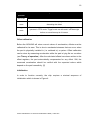
Table 1: FIFO modes of operation .............................................................................. 16
TURKU UNIVERSITY OF APPLIED SCIENCES THESIS | Lukas Kern
5
LIST OF ABBREVIATIONS (OR) SYMBOLS
Remote
short for “remote control”
Control
refers to the control over the controlled machine;
not to be confused with “remote”
CPU
Central processing unit
FIFO
First In First Out (data structure, equivalent to a queue)
ISR
Interrupt service routine, interrupt handler
EABI
Embedded-application binary interface
g
Gravity of Earth (9.81 m/s²)
RTOS
Real Time Operating System
SDA / SCL
Serial data signal / serial clock
CMOS
Complementary metal-oxide-semiconductor
GPIO
General Purpose Input/Output
ODR
Output Data Rate of the ADXL345
AC / DC
Alternating Current / Direct Current
I²C
Inter-Integrated Circuit (serial bus)
GNU Project
A free software, mass collaboration project
Toolchain
A set of programming tools such as compiler and linker
R/W
Read/Write
LED
light-emitting diode
Hz
Hertz, unit of frequency
D[number]
to be detected (functional requirement)
TURKU UNIVERSITY OF APPLIED SCIENCES THESIS | Lukas Kern
6
ND[number]
to be not detected (functional requirement)
D[number]T
to be detected (technical requirement)
ND[number]T
to be not detected (technical requirement)
D[number]I
to be detected (implementation)
ND[number]I
to be not detected (implementation)
D[number]V
to be detected (validation)
ND[number]V
to be not detected (validation)
ms
Millisecond(s)
ns
Nanosecond(s)
µs
Microsecond(s)
TURKU UNIVERSITY OF APPLIED SCIENCES THESIS | Lukas Kern
7
ACKNOWLEDGEMENTS
First of all, I’d like to thank Timo Jääskeläinen for introducing me to this project
and providing me with the opportunity to make valuable technical and
interpersonal experiences. I couldn’t have done this project without the patience
and advice of the colleagues from Technion.
Next, I’d like to thank my supervising tutor and teacher Jari-Pekka Paalassalo
for his thorough guidance in finding a thesis topic and during the work process.
In the same way, I’d like to thank my employer Antti Pasanen who took the time
and effort to give me guidance and valuable feedback despite a lot of other
tasks on his list.
Many people that I met during my student exchange inspired me and made my
stay in Finland a great experience. I want to thank Roni for having been
stubbornly motivating, Till for his support and many inspiring conversations, and
Davide for reminding me how important it is to never give up.
Also, I’m grateful for the love from my mother, my father and Gela, and my
brother Niklas who helped me to continue when I felt demoralized.
TURKU UNIVERSITY OF APPLIED SCIENCES THESIS | Lukas Kern
8
1 INTRODUCTION
When the goal of an application is to provide safety, this requires never-ending
analysis of scenarios that can go wrong. It is difficult to estimate how many
ways there are to use a machine inadequately and if a machine is certified to
comply with modern safety standards, this doesn’t guarantee safety. Instead,
this increases the risk that people feel protected and therefore act carelessly.
This shows that safety can only be increased but never guaranteed.
Timo Jääskeläinen introduced me to Technion Ltd., subsequently referenced as
Technion, where he worked. After an interview about my level of knowledge I
was offered a project for my bachelor thesis and I accepted. Technion is
studying accelerometers in order to find out whether they’re suitable to increase
remote control safety. Accelerometers measure acceleration. They’re used, for
instance, in biology, engineering and everywhere in our daily life, including
gaming and mobile phones. [13]
The remote is used to control vehicles as, for instance, excavators. Due to
inadequate usage or accidents, it may receive uncontrolled input and the
controlled machine could injure nearby humans or damage the environment.
Therefore, the accelerometer is used to observe the status of the remote and
detect abnormal behavior which requires stopping certain commands from
being transmitted to the machine. While increasing safety during remote control
usage, best possible usability should be preserved, i.e. normal behavior such as
standing, walking and sitting with the remote should not interrupt the
transmission of commands.
The goal of the project is to build up a knowledge base related to the usage of
accelerometers and their role in the detection of above mentioned behavior.
Furthermore, code which provides the functionality for the above has to be
produced.
The resulting code is not ready to be used in the final remote product. Its main
purpose is to demonstrate what is possible with an accelerometer and to
examine whether it suits the requirements.
TURKU UNIVERSITY OF APPLIED SCIENCES THESIS | Lukas Kern
9
Chapter 2 gives an overview of the used hardware and software. Chapter 3
discusses the requirements. Chapter 4 describes the implementation of the
solution, points out difficulties and gives reasons for the decisions that have
been made during the work process. Chapter 5 discusses whether the
requirements have been met, validates the applicability of the solution for the
final product and proposes improvements for the future.
2 BACKGROUND INFORMATION
This chapter describes the hardware and software that has been used and
gives an overview over existing similar work (see 2.4). Note that only the most
important background information is described. For details, see the ADXL345
data sheet and the application notes by Analog Devices. [2][3][4]
2.1
Hardware
2.1.1 The remote control
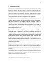
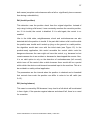
The remote control is designed by Technion and includes an IO expander1 in
combination with a microprocessor and a radio controller to communicate with a
machine. The IO expander is used to support, for instance, joysticks, LEDs and
buttons. For development and testing, a prototype was used which doesn’t
include a radio controller or peripherals because the focus was not the
communication with a machine but testing whether the ADXL345 is suitable to
gather status information. Picture 1 shows the real remote and the prototype
that was used [11].
1
IO expanders increase the amount of available IO pins.
TURKU UNIVERSITY OF APPLIED SCIENCES THESIS | Lukas Kern
10
Picture 1: Technion TRC remote control (left) and the used prototype (right)
2.1.2 ADXL345 accelerometer
The ADXL345 is a 3-axis accelerometer by Analog Devices which can measure
acceleration of up to ±16 times gravity of Earth which is expressed in g, whereat
1 g equals approximately 9.81 m/s² varying slightly depending on altitude,
latitude and other factors in relation to the position of measurement [10]. The
part has an output resolution of up to 13 bit and measures both dynamic
acceleration resulting from movement or shock and static acceleration from
gravity. The latter can be used to measure inclination whereat changes of less
than 1.0° can be resolved. But it isn’t limited to pure acceleration data output.
Instead, it offers special functions that can serve very specific applications (see
paragraph Functions).
The acceleration data can be read from the part’s data registers (see paragraph
Data format and retrieval) and the I²C transmission protocol was used to
communicate with the part (see 2.3 I²C).
Theory of operation
In order to measure acceleration, an accelerometer applies Newton’s second
law of motion,
. It measures the force that acts on an object with a
TURKU UNIVERSITY OF APPLIED SCIENCES THESIS | Lukas Kern
11
known mass, called a proof mass. The most common way to measure this force
is by measuring the dislocation of the proof mass. [12]
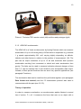
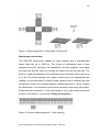
Figure 1 displays the axes of acceleration sensitivity whereat the corresponding
output voltage increases when accelerated along the sensitive axis. For
instance, consider the case where the part is lying flat on an even surface.
Depending on which side of the part is up and which is down, the z-axis is in the
±1-g field of gravity and reads ±1 g and the x- and y-axis are in the 0-g field of
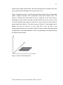
gravity and hence read 0 g. This can be seen in Figure 2. It also shows how to
position the part so that the x- and y-axis are in the 1-g field. If the
accelerometer remains in one position and isn’t moved, each axis experiences
a magnitude of acceleration between 0 and 1 g depending on its alignment with
the earth’s field of gravity.
Figure 1: Axes of Acceleration [2]
TURKU UNIVERSITY OF APPLIED SCIENCES THESIS | Lukas Kern
12
Figure 2: Output response vs. Orientation to Gravity [2]
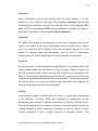
Data format and retrieval
The ADXL345 continuously updates its data registers with a user-specified
output data rate up to 3200 Hz. The format of acceleration data is twos
complement and for each axis, it is separated in two 8-bit registers; one holding
the lower bits and the other one holding the higher bits and the sign bits. The
amount of sign bits depends on the selected output resolution which can be up
to 13 bit. For post-processing, the register values need to be assembled after
reading. It is recommended to read the data registers with a multiple-byte read
so that their content isn’t updated between reading operations. Figure 3 shows
the data format in full-resolution mode which has been used during this project.
Configured with resolution of 13 bit and a range of ±16 g, the z-axis should read
a value of 256 when in 1-g field (see Theory of operation).
Figure 3: Format of data registers in 13-bit mode [4]
TURKU UNIVERSITY OF APPLIED SCIENCES THESIS | Lukas Kern
13
Functions
While acceleration can be read directly from the data registers, it is also
possible to use 8 different interrupts (see paragraph Interrupts) that provide
advanced state information as well as a self-test feature (see paragraph Selftest), a FIFO (see paragraph FIFO) and the possibility to calibrate the offsets of
the axes of acceleration (see paragraph Offset calibration).
Interrupts
The ADXL345 provides 8 interrupts that can be used in different ways to suit
specific user needs. Each of them participates in the Interrupt Source register
only if the respective bit is enabled in the Interrupt Enable register. For more
details on interrupt usage and parameters, see [2] and 4.3 Parameters.
Subsequently, the main characteristics of these interrupts are described.
Free Fall
During a free fall, an object experiences weightlessness. In accelerometers, this
state is represented by an acceleration of 0 g on all axes. Despite its name, the
free fall interrupt can be used to indicate falls in general, not necessarily free
falls [3]. There are two parameters that must be set in order to use the free fall
interrupt: an acceleration threshold and a time threshold. The part will generate
an interrupt when the current acceleration has been below the threshold for
more time than specified in the time parameter.
Activity
It is possible to enable or disable each one of the x-, y- and z-axis to participate
in the detection of activity. When the magnitude of acceleration on any
participating axis exceeds a specified threshold, an Activity interrupt occurs.
The activity interrupt can, for instance, be used in combination with the inactivity
interrupt whereat a small acceleration threshold is used to indicate activity.
Another application is with a bigger threshold to recognize impacts. This
TURKU UNIVERSITY OF APPLIED SCIENCES THESIS | Lukas Kern
14
interrupt can be used in AC- or DC-coupled mode. By default, the DC-coupled
mode is used, i.e. the measured acceleration is compared to the specified
threshold. This mode is used when the magnitude of acceleration is relevant,
e.g. in case of an impact. In AC-coupled mode, again, interrupts are generated
based on the magnitude of the change in acceleration [8]. For instance, this can
be useful if a watch is used to detect constant wrist movement.
Inactivity
The Inactivity interrupt works similar to the Activity interrupt. It occurs when
acceleration is less than the specified threshold for longer than specified by the
time threshold. As with the Activity interrupt, the participating axes can be
configured. This makes it more adjustable than the Free Fall interrupt.
Additionally, AC- or DC-coupled mode can be chosen which works the same
way as for Activity.
In AC-coupled mode, a reference value is taken at the beginning of inactivity
detection and compared to the current acceleration. An interrupt is generated if
the difference is less than the inactivity threshold for the time specified in the
time parameter. The result is that the magnitude of the change in acceleration
matters (and not the magnitude of acceleration).
In DC-coupled mode, the magnitude of acceleration is compared directly to the
specified threshold (see Activity).
Other interrupts
The ADXL345 also provides additional interrupts that have not been used in this
project. One of them occurs when a new sample of output data is available
(Data Ready interrupt). Another one indicates that acceleration greater than a
threshold occurred for less time than a time parameter (Single Tap interrupt).
The Double Tap interrupt includes two single taps separated by a user-specified
time. Tap detection can be useful for applications where it is desired to sense
tilts, for instance motion enabled video games or cell phones.
TURKU UNIVERSITY OF APPLIED SCIENCES THESIS | Lukas Kern
15
The Watermark and Overrun interrupts are primarily useful in combination with
FIFO and are not discussed here since FIFO is not used in this project.
Self-test
The self-test feature provides the possibility to test the accelerometer by moving
the mechanical parts in the same way as acceleration does. Self-test should be
used before a new accelerometer is used for the first time in order to assure
that it is functioning correctly. This test is conducted by measuring two sets of
acceleration data; the first measurement is done with the self-test feature
disabled and afterwards compared to the data measured with self-test enabled.
If the difference is within a threshold, the test is considered successful. The
thresholds depend on supply voltage, temperature, output resolution and output
range.
FIFO
A FIFO, short for First In – First Out, is a data structure that works like a queue.
By default, the FIFO is not operational. If the FIFO is in use, new data is placed
in the FIFO but it’s still accessed via the data registers. A possible FIFO
application is to reduce host processor burden by setting the part to sleep mode
until the FIFO has filled to a user-specified extent and then waking up and
reading the cumulated samples in a burst.
The FIFO holds up to 32 samples of data for each axis and can be used in three
different modes. These modes are compared in Table 1.
TURKU UNIVERSITY OF APPLIED SCIENCES THESIS | Lukas Kern
16
Mode of
Key characteristic
operation
FIFO mode
The FIFO collects data until it is full
Stream
Continues to collect data when full, keeping the latest samples and
mode
discarding the oldest
Trigger
First holds only latest samples (stream mode). After a trigger event it
mode
operates in FIFO mode. Trigger mode can be used if axis data right
before an event/interrupt is of interest.
Table 1: FIFO modes of operation
Offset calibration
Before the ADXL345 will return correct values of acceleration, offsets must be
calibrated for its axes. This is due to mechanical stresses that can occur when
the part is physically installed in (i.e. soldered to) a system. Offset calibration
can be done by measuring acceleration while the part is lying flat on a surface
(see Theory of operation). After the calculated offsets have been written to the
offset registers, the part automatically compensates for any offset. Still, the
measured acceleration should be verified with the expected values which
depend on the part’s sensitivity. [2]
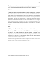
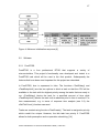
Initialization
In order to function correctly, the chip requires a minimal sequence of
initialization which is shown in Figure 4.
TURKU UNIVERSITY OF APPLIED SCIENCES THESIS | Lukas Kern
17
Figure 4: Minimum initialization sequence [4]
2.2
Software
2.2.1 FreeRTOS
FreeRTOS is a free professional RTOS that supports a variety of
microcontrollers. This project’s functionality was developed and tested in a
FreeRTOS task which will be used in the final product. Subsequently the
features that have been most important for this project are described.
In FreeRTOS, time is expressed in ticks. The functions vTaskDelay() and
vTaskDelayUntil() are the two options to block a task so that the CPU will be
available to the task with the highest priority among the tasks that are ready to
run. vTaskDelay() blocks the task for a specified amount of time while
vTaskDelayUntil() blocks the task until an absolute point in time is reached. For
time measurement, e.g. in terms of response time analysis (see 5.2), the
xGetTickCount() function was used.
Tasks are created using function xTaskCreate(). The task is assigned a priority
which needn’t be unique. However, the idle task has priority 0. FreeRTOS
allows for both preemptive and co-operative scheduling. [14]
TURKU UNIVERSITY OF APPLIED SCIENCES THESIS | Lukas Kern
18
2.2.2 Compiler: Sourcery G++ Lite: ARM EABI
This is CodeSourcery’s version of the GNU toolchain. It includes compilers,
assemblers, linkers and libraries. The version used in this project is 2009q1161.
2.2.3 Serial communication: PuTTY
PuTTY is an SSH and telnet client that has been used for serial communication
with the microprocessor, especially for logging of axis data.
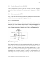
2.3
I²C serial bus protocol
I²C (Inter-integrated circuit) is a multi-master single-ended serial bus standard
that uses only 2 wires between master and slave: SDA (serial data signal) is
used by the host processor (master) for reading and writing and SCL (serial
clock) is set by the processor. It supports 7-bit as well as 10-bit addressing. [2]
Figure 5: I²C connection diagram [2]
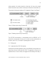
Transmission protocol
Each transmission starts with a start signal and ends with the stop signal by the
master. The start command is followed by a byte with the 7-bit slave address
and the R/W bit which indicates whether the master wants to read or to write.
Next, the slave transmits an acknowledge bit to signal the transmitter (master)
that a byte was successfully received. In case of a reading operation, the
acknowledge bit is directly followed by a data byte from the slave. If it is a
TURKU UNIVERSITY OF APPLIED SCIENCES THESIS | Lukas Kern
19
writing operation, the master transmits a data byte. As long as the master
doesn’t transmit the stop condition, further bytes of data can be transmitted. [5]
The process of writing and reading via I²C is depicted in Figure 6 and Figure 7.
Figure 6: Writing n bytes using I²C protocol [5]
Figure 7: Reading n bytes using I²C protocol [5]
The LPC1768 microcontroller is interconnected with the ADXL345 via I²C
whereat the microcontroller functions as the master and the accelerometer as
the slave. (see 2.3 I²C). The used I²C operating speed is 100 kHz.
2.4
Existing work
2.4.1 Application Note 1023: Fall detection
Analog Devices provides application notes for the ADXL345, among those is an
essay where the part is belt-wired (AN 1023). The application is based on the
experience that, for senior citizens, the biggest risk about falling is the delay or
TURKU UNIVERSITY OF APPLIED SCIENCES THESIS | Lukas Kern
20
absence of help after the accident. It has been used and adapted in this project
(see 4.2 The algorithm).
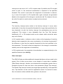
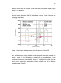
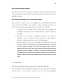
The authors determined four characteristic elements of a fall. A valid fall
situation is only diagnosed if all of these have occurred. Graph 1 shows the
belonging output data.
Graph 1: Acceleration change curves during the process of falling [3]
Here, weightlessness means that the acceleration on all axes goes towards 0 g
(graph 1, phase 1). It is followed by an impact with the ground (phase 2) and
then by motionlessness after the fall (phase 3). The fall involves that the test
person turns over so the acceleration before and after the fall is different
(compare phase 3 and 4).
TURKU UNIVERSITY OF APPLIED SCIENCES THESIS | Lukas Kern
21
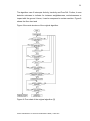
The algorithm uses 3 interrupts: Activity, Inactivity and Free Fall. Further, it uses
detection statuses to indicate for instance weightlessness, motionlessness or
impact with the ground. Hence, it can be compared to a state machine. Figure 8
shows the flow chart and
Figure 9 the code structure of the original algorithm.
Figure 8: Flow chart of the original algorithm [3]
TURKU UNIVERSITY OF APPLIED SCIENCES THESIS | Lukas Kern
22
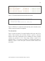
void IRQ_Handler() __irq
// IRQ interrupt
{
if(timer_interrupt)
{
// Increment timer variable. Threshold exceeded?
// What is the DetectionStatus?
// React accordingly...
}
if((IRQSTA&SPM4_IO_BIT)==SPM4_IO_BIT) // External interrupt from ADXL345 INT0
{
// What type of interrupt has occurred?
// What is the DetectionStatus?
// React accordingly...
}
}
Figure 9: Code structure of the original algorithm
The application receives an interrupt either from a timer or externally from the
interrupt pin of the ADXL345 as can be seen above. The interval for the timer
interrupt is 20 ms and if it occurs and, for instance, weightlessness has been
detected, a timer variable is incremented to wait for an activity interrupt that
signals impact with the ground. If this interrupt is not detected in time, this
indicates an invalid status and the algorithm starts over. This process is
displayed in
Figure 10.
TimerWaitForStable++;
if(TimerWaitForStable>=STABLE_WINDOW)
{
// Time out, restart…
}
Figure 10: Role of timer variables in detect_behavior()
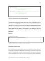
Inclination / position check
After weightlessness, impact with the ground and stability have been detected,
the algorithm compares the difference in acceleration on each axis to the initial
status. If the difference exceeds a certain threshold, this means the user has
turned over and the fall is valid. This is the only opportunity where acceleration
TURKU UNIVERSITY OF APPLIED SCIENCES THESIS | Lukas Kern
23
data is processed by the application. Every other function uses only the part’s
interrupts.
2.4.2 Competitor solution
HBC-radiomatic has implemented similar remote control safety features. [15]
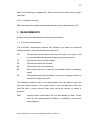
3 REQUIREMENTS
Consecutively, the requirements for this project are listed.
3.1
Functional requirements
The functional requirements defined the following use cases as abnormal
situations which is why they should cause detection:
D0
The operator can fall down to any side (left, right, front, back). A fall
is only valid when the operator ends up lying on the ground.
D1
The remote control can be dropped.
D2
The remote may be left unused.
D3
The remote may receive a shock.
D4
The remote may be in a position that doesn’t allow for adequate
usage
D5
The operator may lose his balance, e.g. due to a slippery surface or
because he steps into a hole.
The following situations were to be distinguished from the above cases and
must not cause detection. The reason is that in the final application, the user
must be able to move around freely while using the remote to control a
machine.
ND0
Jumping down small heights (30 cm) and walking in stairs. These
shall not be misinterpreted as falling or stumbling or the remote
being dropped.
TURKU UNIVERSITY OF APPLIED SCIENCES THESIS | Lukas Kern
24
ND1
The operator is standing still or sitting with the remote on his lap.
This shall not be confused with the remote being left unused.
3.2
Technical requirements
This section examines what is technically required in order to meet the above
requirements. This has been done by looking at the patterns of acceleration of
an event. The patterns were derived by sampling the output data while
executing the use cases of the functional requirements. Section 4.2 discusses
the algorithm that implements the required functions.
Note that a belt was used for the prototype which didn’t prevent it from bouncing
up and down. The result is a bit of “bouncing-noise” that coupled with the output
data. Every case was tested both with and without holding the remote still and
no significant difference was found in the characteristics. Only the overall
acceleration magnitude with bouncing is higher in some cases. Also, the
prototype is lighter so that it is accelerated even faster than the real remote.
D0T
Operator falls: This case has been solved in AN 1023 and is
discussed in 2.4.1.
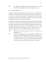
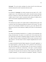
D1T
The remote was dropped from 30 cm height into a cardboard box
padded out with foam. Graph 2 shows the significant elements that
are already known from D0T. The only difference is that in this case
the remote doesn’t turn over which can be seen when comparing
the acceleration pattern at the beginning and end of the graph.
TURKU UNIVERSITY OF APPLIED SCIENCES THESIS | Lukas Kern
25
Graph 2: Acceleration change curves of remote control being dropped
D2T
The remote may be left unused: This means it must be detected
that the acceleration on each axis doesn’t change
D3T
Remote may receive a shock: A sudden high rise in acceleration is
to be detected.
D4T
The remote may be in an invalid position: This requires detection of
how much the acceleration for each axis differs from the initial state
(see Inclination / position check).
D5T
Losing balance: Depending on the direction and intensity of
stumbling or slipping, the data for this case can have various
shapes. However, in general a loss of balance starts with a sudden
increase in acceleration (the cause of the stumbling, e.g. stepping
TURKU UNIVERSITY OF APPLIED SCIENCES THESIS | Lukas Kern
26
in a hole or collision with an object) followed by a loss of balance. If
the operator ends up falling, this is detected by D0T).
Below are examined the technical requirements for the situations that shall not
cause detection.
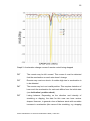
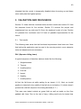
ND0T
The graph below shows the operator jumping down from a height of
30 cm, holding the remote still to prevent it from bouncing. The
similarity to dropping the remote (D1T) is visible, so a characteristic
has to be found in order to distinguish them.
Graph 3: Jumping down from chair
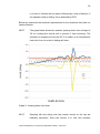
ND1T
Standing still and sitting with the remote control on the lap are
basically equivalent. Since the remote is in use, this situation
TURKU UNIVERSITY OF APPLIED SCIENCES THESIS | Lukas Kern
27
should not be detected as abnormal. The graph below shows that
there is no significant element except for a constant tremor in the
acceleration. Since the magnitude of the tremor is rather small, it
may be difficult to determine that the remote is not left unused.
Graph 4: Standing still with remote
4 REALIZATION
An existing project in C language which uses FreeRTOS (see FreeRTOS) was
used as the underlying code base and an ADXL345 driver was designed that
uses an underlying I²C driver. Throughout the project, the ADXL345 was used
with an output data rate of 100 Hz, ±16 g range and 13 bit output resolution
(see Data format and retrieval), and appropriate values for the offset registers
were determined and are written to the registers every time the device is
powered on (see Offset calibration). They need to be determined only once
after an ADXL has been installed on a system.
A console program was written to facilitate communication with the device and
is described in 4.1.
TURKU UNIVERSITY OF APPLIED SCIENCES THESIS | Lukas Kern
28
A fall detection algorithm from an application note which is described in 2.4.1
turned out to provide a good basis for the detection of abnormal behavior. It
shows how the ADXL345 interrupts can be used to obtain the desired status
information about the part. In most cases, their usage makes it needless for the
application program to process acceleration data directly. The adaptation of the
algorithm is described in 4.2 and the relevant parameters to adjust it in the
future are explained in 4.3.
4.1
Console program
To facilitate the process of development, a console program was written which
can be used in order to read and write the registers of the accelerometer.
Furthermore, it can sample acceleration data and print it to the console. As a
help to test the algorithm, the console program can display a log of the latest
detection statuses which are discussed in 4.2.2.
4.2
The algorithm
4.2.1 gives an introduction to the algorithm and 4.2.2 explains in detail how it
was done using a state machine with detection statuses.
4.2.1 Overview
The result is based on the algorithm described in Application Note 1023 which
has the shape of a state machine (see 2.4.1) and [3]. The technical
requirements (see 3.2) are realized through the accelerometer’s interrupts (see
section Interrupts) whereat the Activity, Inactivity and Free Fall interrupts were
used.
While the original application only raises an alert after a valid sequence of
events was detected (see Figure 14); in the current project, a reaction must
occur as soon as possible. The reason for this is that no more commands shall
be sent to the machine in case of an abnormal situation. Although the goal of
this project was only the detection of abnormal behavior but not the
implementation of appropriate reactions, the places for a later reaction in the
TURKU UNIVERSITY OF APPLIED SCIENCES THESIS | Lukas Kern
29
product-ready application are indicated by the functions enableCtl() and
disableCtl(). They set LEDs and buzzers on the remote in order to indicate the
reason for the reaction (in this case the reaction is enabling or disabling of the
control). The only requirement for an implementation of appropriate reactions is
that each situation has a unique characteristic on the base of which it can be
distinguished from others. 4.2.2 explains how this is done.
However, for the final product, further decisions about how to react will be
necessary. As one example, due to the requirement to detect all abnormal
events, it is difficult to avoid normal events from occasionally leading to
detection. In these cases, the control should only be disabled temporarily and
recover automatically since having to re-enable the control manually is
troublesome for the user if it must be done frequently. On the other hand, it is
obvious to require a manual reset after the operator has fallen, when the remote
is left unused, when it senses a hard impact as well as when continuous
weightlessness is detected (which indicates that the device is falling from a tall
height). These events are not supposed to occur during normal usage and can
be considered critical.
Different from the original algorithm, this one has to detect additional events
besides falls while assuring as little overlap with normal behavior as possible
(see 3.1 Functional requirements). However, in order for the detection to be
reliable, every single abnormal situation must be detected. This requires
sufficiently high sensitivity which may cause even slight, harmless movements
to trigger an interrupt. Since safety cannot be less important than usability, it
must be accepted that there are movements that will temporarily disable the
control. For instance, when walking downstairs, weightlessness may be
detected occasionally. In this case the algorithm will start over and re-enable
the control when the expected strike after weightlessness does not occur, i.e.
the respective timer times out.
TURKU UNIVERSITY OF APPLIED SCIENCES THESIS | Lukas Kern
30
4.2.2 Design
The
detection
of
abnormal
behavior
is
implemented
as
a
function
detect_behavior() that is called by a FreeRTOS task.
The microprocessor doesn’t receive interrupts directly from the interrupt pin of
the ADXL. Instead, polling was used to determine whether this pin was high or
low. The reason is that if an interrupt handler was used, the part could generate
an interrupt flood which would prevent other functions from running. Polling
grants better control over the CPU time that is consumed by the accelerometer.
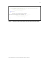
Figure 11 shows the derived function which uses polling.
In the original algorithm, a timer interrupt occurs every 20 ms and the values of
time windows are calculated based on this interval. Since no interrupt handler is
used in the current application, the same time interval was used both as the
task delay and in the algorithm parameters to calculate the time windows. The
interconnection between algorithm logic and task delay might seem like a
disadvantage. However, since the task delay is constant, it’s more suitable than
using, for instance, time stamps in detect_behavior(). Figure 12 shows how the
time windows for the algorithm depend on the delay and
Figure 13 shows how the detection function is used in the context of a
FreeRTOS task.
TURKU UNIVERSITY OF APPLIED SCIENCES THESIS | Lukas Kern
31
void detect_behavior()
{
// Task delay has passed since the last time that we were here
// So increment timer variable
// What is the DetectionStatus?
// React accordingly...
if (int1)
{
adxl345_read_reg(XL345_INT_SOURCE,
&ADXL345Registers[XL345_INT_SOURCE], 1);
// What type of interrupt has occurred?
// What is the DetectionStatus?
// React accordingly...
}
}
Figure 11: Structure of the function derived from the original interrupt handler
TURKU UNIVERSITY OF APPLIED SCIENCES THESIS | Lukas Kern
32
// abnormal_det.h
#define DELAY_XL
20
#define POSITION_WINDOW
500/DELAY_XL
#define STRIKE_WINDOW
200/DELAY_XL
#define STABLE_WINDOW
3500/DELAY_XL
#define FREE_FALL_OVERTIME 300/DELAY_XL
#define FREE_FALL_INTERVAL 100/DELAY_XL
//
//
//
//
//
DELAY_XL
DELAY_XL
DELAY_XL
DELAY_XL
DELAY_XL
ms/LSB
ms/LSB
ms/LSB
ms/LSB
ms/LSB
Figure 12: Correlation between task delay and time windows
portTASK_FUNCTION(vAbnormalTask, pvParameters)
{
detect_behavior();
vTaskDelayUntil(&xLastWakeTime, DELAY_XL);
}
Figure 13: DELAY_XL is used both as the task delay and to calculate correct
values for the time intervals of the algorithm
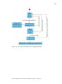
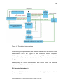
The state machine
Figure 14 shows the states of the original algorithm which were used for the
solution. State transitions with red letters indicate a reaction to abnormal
behavior which wasn’t implemented such as disabling the remote (possible
reactions are examined in 4.2.1). Green letters indicate a restart of the
algorithm (0xF0), i.e. the control is re-enabled. The resulting state machine is
depicted in Figure 15 where bold green connectors indicate transitions that
were added.
TURKU UNIVERSITY OF APPLIED SCIENCES THESIS | Lukas Kern
33
Figure 14: The relevant states of the original algorithm
TURKU UNIVERSITY OF APPLIED SCIENCES THESIS | Lukas Kern
34
Figure 15: The derived state machine
When testing the implementation, the detection statuses that can be seen in the
state machine above are logged for later evaluation on the computer.
Additionally, they’re indicated at run time using LEDs and buzzers which
provide immediate feedback so that the data doesn’t need to be transmitted to
the PC after every test.
Subsequently, the above state machine and how it meets the technical
requirements (3.2) is described in detail.
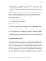
D0I (Operator falling down)
An operator fall is detected in the same way as in the original algorithm which is
described in 2.4.1.
TURKU UNIVERSITY OF APPLIED SCIENCES THESIS | Lukas Kern
35
D1I (Remote being dropped)
If the use case ”operator jumping down” is compared to ”operator falling”, the
difference is that the operator turns over during a fall resulting in a status that is
different from the initial status. However, this criterion doesn’t differ between
”operator jumping down” and “remote being dropped” (compare 3.2 D1T and
ND0T) so that the following sequence of detection statuses is representative for
both:
1. Weightlessness (status 0xF1)
2. Impact with ground (0xF2)
3. Stability (0xF3)
4. Start over since the position equals the initial position (0xF0)
A restart (4.) is appropriate after jumping down but not after the remote was
dropped. In order to tell the events apart it is necessary to look at what happens
afterwards. The following is an idea how these cases can be differentiated. It
hasn’t been implemented because it’s an advanced feature and the goal was
not a product-ready application.
Lying on the ground, the remote will most likely remain completely motionless
which leads to detection as “left unused” sooner or later depending on the
specified inactivity time. However, since the remote is not in hand it is desirable
to have the control disabled as soon as possible. Therefore, the following
actions are reasonable after contact with the ground has been detected:
-
The time parameter for the Inactivity interrupt is decreased so that an
unused remote is detected sooner. It is increased again after a change of
state.
-
At the same time, the acceleration threshold is decreased so that a user who
is moving on or standing still after jumping down doesn’t cause the Inactivity
interrupt (only the remote on the ground shall cause it)
-
Additionally, a timer is necessary while waiting for motionlessness. If it times
out, there has been movement after the fall and it is known that the operator
has jumped down. In this case the algorithm proceeds with the initial status.
TURKU UNIVERSITY OF APPLIED SCIENCES THESIS | Lukas Kern
36
-
That
means
the
sequence
{F1F2F3Inactivityfinal
{F1F2F3F0}
state}
for
a
is
split
remote
up
fall
into
and
{F1F2F3[timeout while waiting for inactivity]F0} if the carrier jumped
down.
When dropping the remote from taller heights the following sequence should be
detected. Different from the above sequence, this one is acceptable because
both jumping down and falling from high places are dangerous and must
therefore lead to detection.
1. Weightlessness (status 0xF1)
2. Continuous free fall (critical, 0xFF)
D2I (Remote left unused)
This situation is detected by the Inactivity interrupt. The parameters are the
inactivity time and the acceleration threshold.
It may seem obvious to exit the state left unused when activity is detected, just
like it was entered due to the detection of inactivity. However, an activity
interrupt may not come from the operator but from the environment and must
not lead to re-activation. Therefore, left unused is a final state that may require
manual reset of the control.
D3I (Remote receiving a shock)
The detection of this event starts with the Activity interrupt which leads to state
0xF6. A shock against the remote is not only detected as an impact after a fall
but also within the initial state. Still, the detection process is the same as during
a fall after weightlessness has been detected and includes the position
comparison at the end. The reason for separating Strike after weightlessness
(0xF2) and Strike/Shock (0xF6) is that the activity acceleration thresholds are
different in both cases. The reason for separating the successive stable
statuses (0xF3 and 0xF7) are different thresholds for the inactivity interrupt in
TURKU UNIVERSITY OF APPLIED SCIENCES THESIS | Lukas Kern
37
both cases (complete motionlessness after a fall vs. significantly less movement
than during a shock/strike)
D4I (Invalid position)
This detection uses the position check from the original algorithm. Instead of
only using it during a fall event, it now constantly monitors the remote’s position,
too. If it is invalid, the control is disabled. If it is valid again, the control is reenabled.
Like in the initial state, weightlessness, shock and motionlessness are also
detected while the position is invalid. If the part didn’t detect a fall or strike while
the position was invalid and it ended up lying on the ground in a valid position,
the algorithm would start over with the initial state (see Figure 15). In the
product-ready application, this would re-enable the control which could be
dangerous because the user might not have the control, e.g. because he lost
consciousness due to an accident or because he has dropped the remote. Also,
it is no valid option to rely on the detection of motionlessness (left unused)
which turns off the control after a while because there would still be a period
within which the device could transmit unwanted input to the machine. This is to
be avoided in a safety-critical application.
The parameters are the interval when the position is checked and a threshold
that controls how much the position can differ in order to be still valid (see
2.4.2).
D5I (Losing balance)
This case is covered by D0I because it may lead to a fall which will be detected
in time. Again, if the operator regains balance and doesn't fall, there is no need
for a reaction.
TURKU UNIVERSITY OF APPLIED SCIENCES THESIS | Lukas Kern
38
ND0I (Operator jumping down)
This case is covered by the sequence of detection statuses mentioned in D1I. It
can be considered as successfully ”not detected” since the algorithm starts over
right after the jump.
ND1I (Operator standing still or sitting with remote)
As pointed out in chapter 3, it is not straightforward to distinguish whether the
remote is left unused (D2I) or the operator is sitting or standing still. Due to a
lack of time this case was not implemented but it can be done like this:
1. A high value for inactivity time can be used. This increases the
probability of detecting minor motions while the operator is sitting or
standing.
2. However, if he remains completely motionless, the detection
algorithm could be interfaced with remote input (e.g. joysticks /
buttons) to determine that the control is still being used
3. Another option is to set the acceleration threshold of the activity
interrupt very low after long time motionlessness has been detected
by the inactivity interrupt. If the activity interrupt occurs within a
specified amount of time (use a timer), there is still movement and the
remote is not left unused. If, however, no activity is detected within
the specified time interval, the remote is identified as left unused. A
suitable value for the activity threshold can be determined by trial and
error.
4.3
Parameters
This section deals with the parameters used to adjust the algorithm.
The main parameters for adjusting the algorithm are the parameters of the three
interrupts that it uses: Activity, Inactivity and Free Fall (see paragraph
TURKU UNIVERSITY OF APPLIED SCIENCES THESIS | Lukas Kern
39
Interrupts). The next section motivates the values (and for the Activity and
Inactivity interrupt the mode of operation) that were used.
Activity
As mentioned in Interrupts, the Activity interrupt can be used in AC- or DCcoupled mode. In the initial state as well as after a free fall has been detected,
the part is looking for a strike and is therefore used in DC-coupled mode. ACcoupled mode is used to detect movements while waiting for stability after a
strike as well as after weightlessness followed by a strike.
Inactivity
This interrupt is only used in AC-coupled mode (for stability detection after a fall
or strike as well as for detecting whether the remote is left unused). The used
value for the acceleration threshold is the same in every case while the time
parameter is shorter for the detection of stability (0xF3) than for motionlessness
(0xFA).
Free fall
The closer the acceleration threshold is to 1 g (which is the acceleration sum
during motionlessness), the easier it is to detect a fall. On the other hand, this
may cause other movements to mistakenly trigger the interrupt. A value close to
0 g, again, will make it easier to distinguish a fall from other movements. In this
case, however, a fall that doesn’t involve complete weightlessness will not be
detected.
A suitable acceleration threshold highly depends on the specific application. In
the original algorithm, a rather big value of 0.75 g has been used so that any
falls can be detected [3]. In this project though, the user moves a lot and the
remote bounces up and down occasionally. In this spirit, a smaller threshold
would prevent normal movements from being confused with safety-critical
movements. On the other hand, the detection of falls would be less reliable with
a smaller threshold, i.e. some would not be detected. Therefore, it must be
TURKU UNIVERSITY OF APPLIED SCIENCES THESIS | Lukas Kern
40
tolerated that the control is temporarily disabled when bouncing up and down
since safety has the highest priority.
5 VALIDATION AND DISCUSSION
Section 5.1 deals with the functional tests and their results and section 5.2 lists
the response times for the solution. Section 5.3 reviews the project and
experiences from my side and 5.4 from the employer’s point of view. Section
5.5 presents the conclusion and 5.6 hints at possible improvements for the
future.
5.1
Test results
The following tests show that the functional requirements have been met. Note
that before the application can be used in the remote product, more extensive
tests and adjustments are necessary.
D0V (Operator falling down)
A typical sequence of detection statuses looks like the following:
1. Weightlessness
2. Timeout
3. Invalid position
4. Free fall
5. Impact
6. Stability
7. Invalid position
At first, the fall times out while waiting for an impact (1.-2.). Next, an invalid
position is detected in the middle of the fall due to inclination (3.) which doesn’t
prevent the valid fall sequence from being detected (4.-7.)
This case was tested outside on grass field as well as inside on the floor
padded with foam. Due to the risk of injury, falling could only be tested less
TURKU UNIVERSITY OF APPLIED SCIENCES THESIS | Lukas Kern
41
severe than it might be in a real situation. Still, the same results as in AN 1023
have been reached while falling to each side and even from small heights
(falling from squat position). The result is satisfying, especially in the context of
other detections.
D1V (Remote being dropped)
This safety feature was tested by dropping the remote into a cardboard box
padded out with foam from different heights.
Either one of the two sequences mentioned in 4.2.2 (D1I) was always detected
successfully. When motionlessness is detected (state 0xF3) and the position
after the fall is equal to the initial position, the control can be re-enabled.
Otherwise the system may shut down.
Note that in the current implementation, this case isn’t distinguished from the
operator jumping down. However, this can be done as described in 4.2.2 (D1I)
and will be necessary before using the application in the final remote where the
user may not want to reactivate the system every time after jumping down from
somewhere. Dropping the remote, however, may require that it shuts down (see
3.1 Functional requirements).
When the device was assigned a free fall acceleration threshold of 0.3 g,
weightlessness was detected from no heights less than 10 cm. With a threshold
of 0.6 g, it was detected till 5 cm. [3] uses even 0.75 g which makes the
detection very reliable but also increases the chance of confusion with other
events as pointed out in 4.2.1.
D2V (Remote left unused)
This case was detected successfully. However, for the end use, it may be
necessary to adjust the time after which the remote is classified as unused.
D3V (Remote receiving a shock)
This case was detected successfully.
TURKU UNIVERSITY OF APPLIED SCIENCES THESIS | Lukas Kern
42
D4V (Invalid position)
This case was detected successfully.
ND0V (Operator jumping down)
As can be seen in ND0I, this situation results in a restart of the algorithm after
the resulting position is found to be equal to the initial position. Therefore, it is
successfully not detected as abnormal behavior if the operator jumps down
small heights. However, if he/she jumps high or jumps down from a place higher
than ca. 40 cm, this is identified as a continuous fall which is a critical event that
must require a manual reset. Either way, the requirement of allowing the
operator to jump down small heights such as 30 cm has been met.
ND1V (Operator standing still or sitting with remote)
As explained in ND1I (see 4.2.2), this case has not been implemented and is
thus misleadingly detected as “remote left unused”.
5.2
Response time analysis
Since the detection has to be sufficiently fast and since it will share CPU time
with other tasks, analysis of response times was required. Subsequently, the
results are discussed.
Since the rise and fall time of the interrupt pin takes some ns, it’s negligible and
the I²C transmission time takes some µs up to a few ms. So only the time for
reading and writing the part’s registers must be examined.
The best case is when no interrupt needs to be processed and
detect_behavior() returns immediately which takes less than 1 ms. If the
function is executed and an interrupt has occurred, the processing time
depends on the I²C transmissions. Depending on the state transition, up to 4
registers are written sequentially which takes approximately 23 ms. During a
position check, 6 sequential registers are read which takes approximately 34
TURKU UNIVERSITY OF APPLIED SCIENCES THESIS | Lukas Kern
43
ms. FreeRTOS function xTaskGetTickCount() was used to measure the times
(see 2.2.1 FreeRTOS).
Since the time between the occurrence of an interrupt and the beginning of its
processing (which is the start of function detect_behavior) varies between 0 ms
and
, the following can be concluded about the time from the
occurence of an interrupt until it has been served:
-
The time is
-
Best case: An interrupt (e.g. the Activity interrupt) occurs right before the
task delay ends. The response time is ca.
-
Worst case: The position check timer indicates that it’s time for a position
check and additionally, an inactivity interrupt occurs after a strike has been
detected (status 0xF2) which leads to another position check. Furthermore,
assume that the inactivity interrupt has occurred right after the task was
delayed with vTaskDelayUntil(). The response time is ca.
Note that these are only the response times for the serving of one interrupt. A
fall event, for instance, involves multiple sequential interrupts in order to be
classified as a fall.
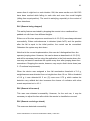
5.3
Personal learning experience
This project was very enriching. On the one hand, it was incredibly valuable to
gather an understanding of the commercial context of such a project. It required
several iterations during the work process in order to find out which factors are
relevant and which are rather a waste of time. On the other hand, it was
challenging to abstract from the elements in the work process in order to build a
logical thesis text.
TURKU UNIVERSITY OF APPLIED SCIENCES THESIS | Lukas Kern
44
5.4
Employer’s feedback
According to Technion, the goals of the project were met and the resulting data
samples, code and documentation, as well as this thesis, are useful for future
work.
5.5
Conclusion
The required knowledge was gathered and accelerometers, in particular the
ADXL345, have proven suitable for the application, and the detection and
differentiation has been implemented successfully. Although not every case was
implemented, the goal was achieved because it was examined how this can be
done (see 5.1).
One drawback is that a complete separation of normal and abnormal situations
was not achieved. Due to the required sensitivity, it was not feasible to avoid
some false detection in the first place. However, when using the application in
the final product, the control can be re-enabled right after a detection has
proven to be “false alarm”.
5.6
Future improvements
Due to a lack of time, the present solution does not provide the best possible
usability since it was the goal to detect all situations. Before it can be used in
the product, the thresholds and times of the algorithm have to be adjusted to
increase usability and reliability.
Furthermore, since the ADXL345 offers many specific features that haven’t
been the focus of this project, they could be used in the future. For instance, the
part’s FIFO can be used in order to reduce host processor burden. In order to
save power, low power mode, sleep mode and link mode can be used. In link
mode activity is only detected if inactivity has been detected last and vice versa.
[2][16]
TURKU UNIVERSITY OF APPLIED SCIENCES THESIS | Lukas Kern
45
Also, it might be good to use a successor model of the ADXL345. The ADXL346
offers some enhancements whereat the main difference is lower power
consumption.
REFERENCES
[1] A Brief History And Overview Of The Accelerometer. Online article.
Available from: http://www.beembee.com/2011/a-brief-history-and-overviewof-the-accelerometer [cited 6.2012]
[2] ADXL345 data sheet, Rev. C. PDF document. Available from
http://www.analog.com/ADXL345 [cited 6.2012]
[3] Application Notes 1023. PDF documents. Available from:
http://www.analog.com/en/mems-sensors/mems-inertialsensors/adxl345/products/technical-documentation/index.html [cited 6.2012]
[4] Application Notes 1077. PDF documents. Available from:
http://www.analog.com/en/mems-sensors/mems-inertialsensors/adxl345/products/technical-documentation/index.html [cited 6.2012]
[5] UM10204 I2C-Bus Specification and User Manual, NXP, Rev. 03—19 June
2007. Available from
http://www.nxp.com/documents/user_manual/UM10204.pdf [cited 6.2012]
[6] Accelerometer. Wikipedia article. Available from:
http://en.wikipedia.org/wiki/Accelerometer [cited 6.2012]
[7] I²C. Wikipedia article. Available from: http://en.wikipedia.org/wiki/I2c
[cited 6.2012]
[8] Analog Devices support forum. Available from:
http://ez.analog.com/welcome [cited 6.2012]
TURKU UNIVERSITY OF APPLIED SCIENCES THESIS | Lukas Kern
46
[9] ADXL345: Question about reference values for AC-coupled mode. Forum
thread. Available from: http://ez.analog.com/message/51880#51880
[cited 6.2012]
[10]
Gravity of Earth. Wikipedia article. Available from:
http://en.wikipedia.org/wiki/Gravity_of_Earth [cited 6.2012]
[11]
Technion Wireless controllers. Website. Available from
http://technion.fi/wireless_controllers.html [cited 6.2012]
[12]
Graham, B. B., 2000. Using an Accelerometer Sensor to measure
Human Hand Motion. Thesis. Available from http://wwwmtl.mit.edu/researchgroups/MEngTP/Graham_Thesis.pdf [cited 6.2012]
[13]
Noton, A., 2011. A Brief History And Overview Of The
Accelerometer. Article. Available from: http://www.beembee.com/2011/abrief-history-and-overview-of-the-accelerometer [cited 6.2012]
[14]
FreeRTOS Quick Start Guide. Website. Available from:
http://www.freertos.org/FreeRTOS-quick-start-guide.html [cited 6.2012]
[15]
Remote control safety features. Website. Available from:
http://www.hbc-radiomatic.com/en/Products/Special-functionsfeatures/Details/items/Safety-features.html [cited 6.2012]
[16]
Application Notes 1025. PDF documents. Available from:
http://www.analog.com/en/mems-sensors/mems-inertialsensors/adxl345/products/technical-documentation/index.html [cited 6.2012]
TURKU UNIVERSITY OF APPLIED SCIENCES THESIS | Lukas Kern