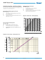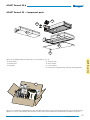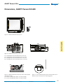
1
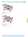
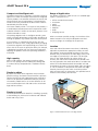
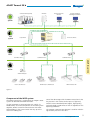
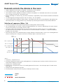
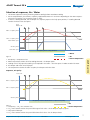
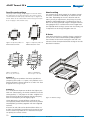
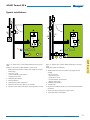
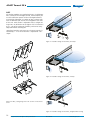
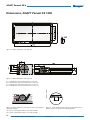
ADAPT Parasol EX b
Energy-saving, suspended comfort module for Swegon’s
WISE System for demand-controlled ventilation
www.eurovent-certification.com
www.certiflash.com
ADAPT Parasol EX b
►► Suspended comfort modules for demand-controlled
ventilation and Swegon’s WISE system.
Primary airflow:
Up to 55 l/s
►► Energy-efficient operation since the room is ventilated,
heated and cooled exactly as called for by the load,
neither more nor less.
Pressure range:
50 to 150 Pa
Total cooling capacity:
Up to 1930 W
Heating capacity:
Up to 2450 W
Size:
690 x 690 mm
►► Highest possible comfort with provision for individual
control on the product or at room level.
►► Waterborne cooling and heating.
690 x 1290 mm
Height 230 mm.
►► Draught-free indoor climate, 4-way air distribution
and Swegon’s ADC (Anti Draught Control) provide
maximum comfort and flexibility both today and for
future needs.
1
ADAPT Parasol EX b
Flexibility
The easily adjustable nozzles in combination with Swegon’s ADC (Anti Draught Control) offer maximum flexibility for future changes in the room layout. All sides of
the unit can be set independently of one another and
this enables the comfort module to distribute more air or
less air to each of the four sides and deliver the air in the
preferred direction in the room.
Design
ADAPT Parasol EX comfort module
The ADAPT Parasol EX is based on a standard Parasol EX
but is also equipped with functions for demand control
of the indoor climate. Available as single and two-module
units:
Sizes:
690 x 690; 690 x 1290
Modules:
Supply air and cooling
Supply air, cooling and heating
Installation:
Suspended, close to ceiling
Function
The essential function of the comfort modules is closely
related to that of climate beams. The major difference
is that comfort modules distribute air in four directions
instead of two. This maximizes the area for the induction
of room air with the supply air which enables the modules to deliver a high capacity without occupying more
ceiling space than necessary. The comfort modules are
also optimized to quickly mix the supplied air with the
room which provides better comfort in the room. In heating applications, this technique also ensures heat is conveyed along the ceiling in a better way. The built-in DCV
function assumes that the duct pressure is maintained
constant by means of a zone damper for example.
The face plate of the ADAPT Parasol EX is available in
three different perforation patterns. As standard, the
face plate has round perforations arranged in a triangular
pattern however other optional patterns are available to
special order.
Draught-fee indoor climate
The ADAPT Parasol EX distributes air in four directions at
low air velocity. The low air velocity is created by distributing air cooler than room temperature over a large area.
The special design of the outlet creates a turbulent flow
enabling the supply air to be quickly mixed with the room
air. The comfort module’s closed design with a circulation
opening for recirculated air in the face plate of the module
also contributes to its excellent mixing performance.
The ADAPT Parasol EX is available in the following coil/
heat exchanger variants:
Variant A: Supply air and waterborne cooling from coil.
Variant B: Supply air, waterborne cooling and heating
from coil.
Demand-controlled indoor climate
Demand-controlled ventilation involves ventilating and
conditioning the air in a room precisely to meet our needs
– no more and no less. The potential for savings is substantial, especially in premises where there is considerable
variation between low and high load conditions in rooms
and during times when there are few or no occupants which is the case in many premises. Offices for example
have in many cases an occupancy rate of less than 50 %!
The ADAPT Parasol EX combines the best attributes from
two worlds – demand-controlled ventilation with all its
potential for savings combined with the comfort module’s high capacity and performance for air conditioning
rooms.
2
Swegon reserves the right to alter specifications.
2015-03-31
www.swegon.com
ADAPT Parasol EX b
Figure 1. Variant A: Cooling and supply air operation
1 = Primary air
2 = Induced room air
3 = Primary air mixed with chilled room air
ADAPT Parasol EX b
Figure 2. Variant B: Heating and supply air operation (also
includes cooling operation)
1 = Primary air
2 = Induced room air
3 = Primary air mixed with heated room air
Swegon reserves the right to alter specifications.
2015-03-31
www.swegon.com
3
ADAPT Parasol EX b
Compact and intelligent unit
The ADAPT Parasol EX is supplied as a compact and intelligent unit in which the damper and motor are integrated
into the product. The controller with pressure sensor and
wiring terminals are pre-mounted on a mounting plate,
which can be easily fitted onto the duct where it will be
concealed by the duct casing.
The sensor module, which is a vital part of the product, is
a combined presence detector and a temperature sensor.
Its default location is within the face plate, however it can
also be mounted on a wall.
The package together with its intelligent control system
where numerous adaptations can be made, contribute to
making the product very flexible and future secure proof.
As an example, it is noteworthy that all the units can
operate as master or slave, simply adjustable by changing
a parameter together with repositioning an RJ cable. This
means that in the event an open-plan office, for example,
is divided up into office cells, the extra work involved in
adapting the product to the new operating conditions is
minimized.
High capacity
With its high capacity, the ADAPT Parasol EX utilizes
40-50% less ceiling area for handling the cooling load
in a normal office, compared with a traditional climate
beam.
Simple to adjust
By means of built-in nozzle regulation with numerous
possible settings, the ADAPT Parasol EX offers optimum
comfort and can be easily adapted to meet a change in
room size or operations conducted inside the premises.
The comfort module can be set so that different air volumes are diffused on each side and can be set for both
high and low airflows.
Range of Application
The ADAPT Parasol EX is ideal for use as a standard application in such premises as:
•
•
•
•
•
•
•
Offices and conference rooms
Classrooms
Hotels
Restaurants
Hospitals
Shops
Shopping centres
With its numerous possible settings, the functions of the
ADAPT Parasol EX can easily be adapted to new businesses or changes in the design of the premises.
Location
Since each side of the ADAPT Parasol EX is individually
adjustable to provide the appropriate airflow, the comfort modules can be positioned anywhere in the room.
Whether they are located at the front edge, centre, and
rear edge or symmetrically in the room is of no importance. In rear edge solutions for cellular offices, for
instance, the unit can be installed near the corridor wall.
The only operation that needs to be done is to reduce the
volume of air distributed towards the corridor wall and
instead open up more on the three other sides (see Figure
3). This is of benefit in comparison with other rear-edge
solutions, because you can make use of the partition
walls to increase the air mixing zone. This provides low air
velocities and a healthy room climate.
Simple to install
The small dimensions offer benefits in handling, especially
at the building site, with easier installation and reduced
health and safety issues.
Figure 3. ADAPT Parasol EX as a rear-edge solution
4
Swegon reserves the right to alter specifications.
2015-03-31
www.swegon.com
ADAPT Parasol EX b
truktur
Chiller and heat pump
NESTOR
truktur
System
Internal network/
Internet
Central intelligent
building automation
System
System
system
truktur
truktur
system
Zone
System
Subsystem
All Year Comfort
Super WISE
System
Zone
Room
system
GOLD
system
Room
roduct
Zone
Zone
roduct
) Zone
parts
Room
CONTROL Zone
CONTROL Zone
CONTROL Zone
ADAPT Parasol EX b
)Room
parts
onents
roduct
Room
roduct
onents
) parts
ADAPT Damper
) parts
onents
onents
Passive air diffusers
ADAPT active air diffusers
ADAPT Parasol EX
Figure 4.
Component of the WISE system
The ADAPT Parasol EX is a component of Swegon’s WISE
System for demand-controlled ventilation.
Via the SuperWISE, a communication unit, which, via
Modbus RTU, ties all the components in the WISE system
together, ADAPT Parasol EX communicates with other
WISE products in the system and all the way up to the
GOLD air handling unit.
Swegon reserves the right to alter specifications.
One of the advantages with the ADAPT Parasol EX is that
the pressure in the nozzles can be kept at a high level,
and this means controlled throw lengths, high capacity
and maintained Coanda effect of the air regardless of the
operating conditions.
The Swegon CONTROL Zone damper is used for maintaining constant pressure in the zone.
2015-03-31
www.swegon.com
5
ADAPT Parasol EX b
Demand-controls the climate in the room
• Stepless regulation of the airflow as required – temperature or the air quality.
• If an air quality sensor is used, it overrides the temperature sensor.
• Same stepless function regardless of whether it concerns one product in an individual-room office or several products in an open-plan office or a conference room.
• Besides ventilating in an efficient way, the room temperature is regulated by means of both waterborne and airborne
cooling.
• Can advantageously discharge heated air from the ceiling – all in one product
• Can be combined with radiators or floor heating – the product then takes this into consideration and regulates the
room temperature in an energy-efficient way, for example by increasing the airflow on increased heat demand.
Selection of sequence, Water / Air
• T he control sequence involves prioritising waterborne cooling before airborne cooling
• For an occupied room, the airflow is steplessly regulated between min. and max. depending on the room temperature (or the air quality if an air quality sensor is used).
• If the room needs to be cooled, ensure first that the airflow generates sufficient pressure in the module which
will allow the water valve to open. The reason for this is to ensure comfort in the room, i.e. to prevent cold down
draughts from the product.
• After that the water valve is allowed to open to supply chilled air to cool the room. If there is still a cooling demand
when the cooling valve is fully open, the built-in air damper opens to cool more with air.
Flow
Water / Air
1
2
3
4
5
6
Max. occupancy flow
Min. P cooling valve
Min. occupancy flow
Valve 100% open
Vacancy flow
Valve 0% open
Occupancy with cooling demand
Figure 5.
1. Occupancy – temperature rises
2. The room temperature reaches level for cooling demand – air damper opens in order to reach minimum pressure
which alllows cooling valve to open.
3. Cooling valve is allowed to open
4. Cooling valve is fully open but there is still a cooling demand in the room – the air damper opens in order to cool
with more air
5. Cooling valve and air damper fully open
6. The temperature reaches the room set point; the damper and valve close
= Water
= Air
= Room temperature
6
Swegon reserves the right to alter specifications.
2015-03-31
www.swegon.com
ADAPT Parasol EX b
Selection of sequence, Air / Water
• T he control sequence involves prioritising airborne cooling before waterborne cooling
• For an occupied room, the airflow is steplessly regulated between min. and max. depending on the room temperature (or the air quality if an air quality sensor is used).
• If there is a cooling demand, the air damper first steplessly opens to the fully open position; if a cooling demand
remains the water valve also opens.
Flow
Water / Air
1
2
3
4
5
Max. occupancy flow
Min. occupancy flow
Valve 100% open
Vacancy flow
Valve 0% open
Occupancy with cooling demand
= Water
= Air
Figure 6.
Sequence, Air quality
Flow / Air
1
2
4
3
Max. occupancy flow
Min. occupancy flow
Vacancy flow
Occupancy with increased airflow to improve air quality
= Air
Figure 7.
= Room temperature
1. Occupancy – CO2 / VOC content rises
2. CO2 / VOC content reaches the permissible upper limit value – the air damper steplessly opens
3. Fully open air damper
4. CO2 / VOC content reaches the permissible lower limit value – the air damper closes
Swegon reserves the right to alter specifications.
2015-03-31
www.swegon.com
7
ADAPT Parasol EX b
= Room temperature
1. Occupancy – temperature rises
2. Room temperature reaches level for cooling demand – air damper opens
3. Cooling valve is fully open but cooling is still required in the room – the valve opens in order to cool with water
4. Air damper and water valve fully open
5. The temperature reaches the room set point; the damper and valve close
ADAPT Parasol EX b
Operating mode
Depending on the status of connected sensors, the
controller adjusts the outputs from any of several possible
operating conditions.
The operating conditions based on occupancy in the
room, the status of the sensor in use or signals from a
main control system are described below.
Operating modes
There are numerous functions in the ADAPT Parasol EX:
•
Occupancy mode.
•
No occupancy mode.
•
Holiday.
•
Stand-by, idle mode.
•
Emergency mode.
•
•
Stand-by, idle mode
When the control system registers that a window is open,
the controller switches over to the Stand-by mode. When
the window is closed, the controller switches over to the
Occupancy mode. The controller is in the Stand-by mode,
the room temperature is kept above 10°C (frost protection).
Emergency mode
In the event of a fire alarm, the controller opens or closes
the air damper in the extract air duct, depending on how
the control system is set. In the Emergency mode, cooling and heating are switched off. Supply air is normally
switched off.
The Emergency mode can only be managed in control
systems that are connected to a main control system via
Modbus RTU.
Commissioning.
Summer night cooling.
Occupancy mode
When the ADAPT Parasol EX receives signals via presence
detector indicating that someone is in the room, the valve
actuator for chilled water or heating water as the case
may be is controlled according to the selected temperature setpoint for cooling or heating associated with this
operating mode. The airflow is controlled to the preselected occupancy flow, but is influenced of course by sensors such as condensation sensors, temperature sensors,
window contacts, air quality sensors, if required, etc.
No occupancy mode
When the No occupancy mode function is active, the
system automatically switches over to the energy-save
mode. The system returns to the Occupancy mode and
normal operation when occupancy is registered again.
In the energy-save mode/no occupancy mode, the valve
actuator is controlled to regulate the chilled water flow
or hot water flow according to the status on other sensors in the room, but normally with a greater permissible
deadband from the temperature setpoint for cooling or
heating than in the occupancy mode, whilst the air is
controlled to the min. flow setting.
Commissioning level
The “First open” function involves having the water
valves open while the installation work is in progress,
which simplifies filling, pressure testing and venting the
water system
The function will be automatically deactivated after
approx. 6 minutes while the system is energised.
A clicking noise can be heard when the valves and dampers change over to the NC mode (normally closed) and
the normal control function is activated.
Further particulars of the commissioning mode can be
read in the description of the sensor module on page 12.
Summer night cooling
The function involves the use of cold air from outdoors
for cooling the room at night to the predefined level.
The function can only be handled in the control system
that is connected to a main control system via Modbus
RTU.
Holiday.
When the Holiday operating mode is active, the system
automatically switches over to the energy-save mode just
as in the case of the No Occupancy mode, but with scope
for allowing further greater temperature differential. Controlled from a main control system.
8
Swegon reserves the right to alter specifications.
2015-03-31
www.swegon.com
ADAPT Parasol EX b
Functions
SWICCT:
Change over
The function involves the use of only one valve actuator
which should be wired to the cooling output terminal.
This actuator then controls both the heating water and
the chilled water, which is transported in the same pipe.
An external temp. sensor should be used and this component should take measurements on the pipe through
which water always circulates.
In winter, when heating is required, the valve opens if
the water in the pipe is warmer than the temperature set
point. If the water is colder, the valve does not open.
In summer, when cooling is required, the valve opens if
the water in the pipe is colder than the temperature set
point.
GT1
GT2
RE
External temperature sensor use
Change over temperature
Not used
Room temperature
Change over temperature
Temperature (read only)
Window contact NO
Window contact NC
Figure 9.
Exercising of valves
The function involves exercising the water valves regularly
by means of automatic control equipment to prevent
them from seizing or becoming stuck. During the exercising process, all the valves wired to the controller open to
the max. setting for 6 minutes and then close. The valves
of the cooling system are exercised first; after that the
valves of the heating system are exercised.
Room
Figure 8.
• 2-pipe system with chilled water in the summer and
heated water in the winter
• GT1 is located where heated or chilled water always
circulates
• Summer: If the room temperature T2 is higher than the
water temperature T1 the valve opens if there is a cooling demand.
• Winter: If the room temperature T2 is lower than the
water temperature T1 the valve opens if there is a heating demand.
• GT1 is wired to the controller as an external temperature sensor.
• In the SWICCT or SuperWISE, the operator has enter a
setting in the controller indicating that the sensor is to
be used for Change-Over operation.
• GT2 is the temperature sensor that is mounted in the
Sensor module
• The valve actuator should be wired to the cooling
output of the controller.
Swegon reserves the right to alter specifications.
2015-03-31
www.swegon.com
9
ADAPT Parasol EX b
Frost protection
The function involves starting heating operation at 10°C
to prevent the risk of damage that otherwise could occur
due to freezing.
ADAPT Parasol EX
ADAPT Parasol EX b
Specific nozzle settings
To specify nozzle settings, always begin from the side where
the water pipes are located. From there, proceed in counterclockwise direction and specify side after side, see Figures 10
and 12. Units can be ordered with nozzles factory-preset (this
does not apply to units held in stock).
Nozzle setting
The unique built-in nozzle control in the ADAPT Parasol
EX makes it possible to individually set each one of the
four sides. Depending on the unit’s location and the
room’s primary air requirement, the primary air can be
guided in all desired directions. The direction of the airflow can be easily optimized using the Swegon ProSelect
sizing program that is available from www.swegon.com.
The required nozzle setting is preset from the factory, but
if required it can be simply changed at the site.
K-factor
Figure 10. Top view, sides 1-4
ADAPT Parasol EX 690
Figure 12. Example 1.
A = 2.1 l/s, B = 15.3 l/s
Figure 11. Top view, sides 1-4
ADAPT Parasol EX 1290
Each nozzle setting has a specific K-factor. A total K-factor for the unit can be determined by adding together
the K-factors for the nozzle settings on each side. The
relevant K-factor for optimized nozzle setting can also be
obtained in ProSelect.
Figure 13. Example 2.
A = 5.8 l/s, B = 15.3 l/s
Example 1:
Nozzle setting LHLH produces the lowest possible No
Occupancy flow (sides 1 + 3 open). This produces a min.
flow/no occupancy flow of approx. 4 l/s and a max. flow
of approx. 35 l/s at pi = 70 pa
Example 2:
If it is instead more important to obtain the highest possible max. flow/capacity, the nozzles should be set to the
HHHH position, i.e. fully open on all sides. A higher max.
flow will then be obtained, however the No Occupancy
flow will consequently also be slightly higher.
Figure 14. Nozzle setting
These adjustments are only different settings on the
same physical product which makes the unit very flexible
and adaptable, particularly together with the integrated
software.
K-factors for each side can be obtained from Tables 2-5
or from the installation instructions on the Internet, however the easiest way to do this is in ProSelect where you
can quickly test various variants.
10
Swegon reserves the right to alter specifications.
2015-03-31
www.swegon.com
ADAPT Parasol EX b
The sensor module
The sensor module consists of a presence detector and a
temperature sensor in the same unit.
This component is mounted as standard in the face plate
on the ADAPT Parasol EX but it can also be ordered as
an accessory for wall mounting, and in that case either
recessed in a standard electrical component box or
surface-mounted on the wall.
By pressing the appropriate buttons on the sensor
module, you can adjust the temperature in the room, set
the ADAPT Parasol EX to the commissioning mode and
read the alarm list.
6 light-emitting diodes indicate in the normal mode which
temperature level has been selected. If an error occurs,
the current alarm is shown as a series of flashes that are
translatable using an alarm list.
Use an RJ12 cable to connect the sensor module to the
controller.
The floor area covered by the presence detector is approx.
24 m2 if it is mounted at a height of 2.7 metres above the
floor and in parallel with the floor.
Entering temperature adjustments
To raise the temperature setting,
press down the
right-hand button.
Each diode corresponds to a one degree increase or decrease of
the set point. The base setting of temperatures is entered in
SWICCT or SuperWISE
Presence detector
Diodes for temperature,
commissioning or alarm
indication
Figure 17. The CABLE CONVERTER USB-RJ12 (RS485) cable can
be easily used for connecting a computer to the module for e.g.
entering software settings. The cable can be connected either
to a socket on the rear of the Sensor module as illustrated, or
directly to the controller. How this is done is described in the
SWICCT user's manual.
Function buttons
Diode-indicating function
- Green = Ok
- Yellow = Alarm
- Green/Yellow = Comfort alarm
(not acute)
Temperature sensor
Figure 15. Sensor module viewed from the front
ON
1 2
3 parallel RJ12 ports (Modbus) for connecting a
controller for instance, another sensor module or
computer by means of Cable converter USB-RJ12
Addressing the sensor module. 10 sensor modules can
be connected to each master unit. Each one must have
its own unique address in order to work.
Switch for termination resistance. Set Switch 1 to the
ON position for the last sensor module in the loop.
Figure 16. Sensor module viewed from rear
Swegon reserves the right to alter specifications.
2015-03-31
www.swegon.com
11
ADAPT Parasol EX b
To lower the temperature setting, press
down the left-hand
button.
ADAPT Parasol EX b
SWICCT
SWICCT (SWegon Indoor Climate Configuration Tool) is the software that makes the entering of settings into the controller a simple task.
Here you can make all the necessary settings for the Product, for example:
•
•
•
•
Base settings for temperature
how to use external sensors, e.g. for air quality
Airflows
Commissioning
SWICCT can be downloaded from www.swegon.se; both the software and a separate manual.
12
Swegon reserves the right to alter specifications.
2015-03-31
www.swegon.com
ADAPT Parasol EX b
Typical installations:
2
GP
2
2
2
GP
GP
GP
x3
3
RE
RE
1
1
4
5
3
6
4
1. ADAPT Parasol EX comfort module with supply air, cooling
and heating
• Pressure sensor
• Communication unit/controller
• Damper with motor.
2. CONTROL Zone damper
3. Extract air diffuser
4. Cooling water and heating water
5. Extract air via transfer air grille to the corridor
6. External sensor module (occupancy and temperature sensor)
Swegon reserves the right to alter specifications.
5
Figure 19. Typical room 2 shows ADAPT Parasol EX in an office
room
Supply and extract air in balance.
1. ADAPT Parasol EX comfort module with supply air and
cooling
• Pressure sensor
• Presence detector
• Temperature sensor
• Communication unit/controller
• Damper with motor.
2. CONTROL Zone damper
3. Chilled water
4. Extract air via ADAPT Damper slave-controlled from ADAPT
Parasol EX
5. Grill or fully opened extract air register (EXC)
6. Sound attentator CLA/SORDO
2015-03-31
www.swegon.com
13
ADAPT Parasol EX b
Figure 18. Typical room 1 shows ADAPT Parasol EX in an office
room
Extract air via transfer air grille (balance at zone level)
6
ADAPT Parasol EX b
ADC
All comfort modules are supplied with ADC air deflectors.
ADC stands for Anti Draught Control, which enables you
to set the diffusion pattern of the air being distributed
to avoid risk of draught. A number of ADC sections with
four air deflectors per section are arranged on each side
of the unit. Each section is adjustable from a straight setting to 40° air deflection to the right or left in increments
of 10°. This offers enormous flexibility and can be easily
adjusted without affecting the
sound level and the static pressure. The water capacity is
reduced by 5 - 10% when the ADC is adjusted to "Fanshape".
Figure 21. Possible settings for the ADC, Fan-shape
Figure 22. Possible settings for the ADC, X-shape
Figure 20. ADC, setting range from -40° to +40° in increments
of 10°
0°
Figure 23. Possible settings for the ADC, Straight airflow setting
14
Swegon reserves the right to alter specifications.
2015-03-31
www.swegon.com
ADAPT Parasol EX b
Technical data
Recommended limit values
Pressure levels
Total cooling capacity, max.
1930 W
Working pressure, coil, max.
Total heating capacity, max.
2450 W
Test pressure, coil, max.
2400 kPa *
* Applies to module without installed control equipment
Airflow
Single module unit
Two-module unit
7-34 l/s
9-55 l/s
Nozzle pressure
50-150 Pa
Recommended lowest nozzle pressure if
coil heating is used, pi70 Pa
Length
Single module unit
Two-module unit
1600 kPa *
Recommended lowest nozzle pressure with
the face plate in the high capacity position, pi 70 Pa
690 mm
1,290 mm
Water flow
Width690 mm
Ensures evacuation of any air pockets in the system.
Height230 mm
Cooling water, min.
0.030 l/s
Dimensions of the units have a tolerance of (±2) mm.
Heating water, min.
0.013 l/s
Temperature differentials
690 A
2-5 K
Heating water, drop in temperature
4-10 K
Temperature differences are always expressed in Kelvin (K).
Table 1. Weight
ADAPT Parasol EX
Chilled water, temperature increase
Flow temperature
Dry
weight
Chilled water
volume
Heating water
volume
21.4
20
21.2
Heating water, max.
** Chilled water must always be kept at a level that ensures
that no condensation will form.
22.6
20.6
22.1
1290-A
34.4
30.8
32
1290-B
39.1
34.8
37.2
60ºC
ADAPT Parasol EX b
690-B
Chilled water**
Exkl. sensor module 0.1 kg.
Designations
P
Power consumption
Power consumption for dimensioning transformer:
Capacity (W)
tl
Temperature of the primary air (°C)
tr
Temperature of the room air (°C)
tm
Mean water temperature (°C)
∆Tm
Temperature differential tr- tm (K)
Actuator
6 VA
∆Tl
Temperature differential tl- tr (K)
Damper motor
2 VA*
Controller
1 VA*
∆Tk
Temperature differential between the cooling water inlet flow and return (K)
Sensor Module
1 VA*
∆Tv
Temperature differential between the heating water inlet flow and return (K)
v
Water velocity (m/s)
q
Airflow (l/s)
p
Pressure (Pa)
∆p
Pressure drop (Pa)
* Allways included in product
Example A:
ADAPT Parasol EX 1290-B-HF; 6+2+1+1 = 10 VA
6 VA for cooling OR heating actuator as the normally operate
in sequence.
Supplementary index: k = cooling, v = heat, l = air, i = commissioning, corr = correction
Example B:
ADAPT Parasol EX 1290-B-HF; 6+6+2+1+1 = 16 VA
For Radiator Heat and Cold draught protection, means 6+6 VA
for actuators as they don´t operate in sequences.
Nozzle pressure (commissioning pressure)
pl = (ql / kpl) 2
pl Nozzle pressure (Pa)
ql
Primary airflow (l/s)
kpl Pressure drop constant for nozzle setting, see Tables 2-3
Swegon reserves the right to alter specifications.
2015-03-31
www.swegon.com
15
ADAPT Parasol EX b
Cooling
Corrected capacity – water flow
Standard
The cooling capacities have been measured in conformance with EN 15116 Standard and have been recalculated
for a constant water flow according to Diagram 2/3.
Different water flow rates to some extent have effects
on the capacity output. By checking obtained water flow
against Diagrams 2 or 3, the capacity indicated in Tables
2-3 may need to be slightly adjusted up or down.
Pcorr = k · Pk
PcorrCorrected capacity (W)
Calculating formulae – Cooling
Below are formulae that enable the user to calculate what
comfort module is best suited for the application. The
values for the calculations can be taken from the tables.
Pressure drop in cooling coil
∆pk = (qk / kpk) 2
∆pk qk
k
Correction factor
Pk
Cooling capacity of the water
Diagram 2. Corrected capacity – Water flow, ADAPT
Parasol EX 690
Pressure drop in cooling coil (kPa)
Flow of chilled water (l/s), see Diagram 1
kpk
Pressure drop constant for cooling coil, see Tables 2-3
Cooling capacity of the air
Pl = 1.2 · ql · ∆Tl
Pl
Primary air cooling capacity (W)
ql
Primary airflow (l/s)
∆Tl
Temperature differential between primary air (tl) and room air (tr) (K)
Cooling capacity of the water
Pk = 4186 · qk · ∆Tk
Pk Cooling capacity of the water (W)
qk Chilled water flow (l/s)
∆Tk Temperature differential between the cooling water inlet flow and return (K)
Diagram 3. Corrected capacity – Water flow, ADAPT
Parasol EX 1290
Diagram 1. Water Flow – Cooling Capacity
Pk (W)
1500
Tk (W) (°K) = 5 °K
4 °K
1250
3 °K
1000
2 °K
750
500
1 °K
250
0
0,03
0,04
0,3
16
0,05
0,4
0,06
0,5
0,07
0,6
0,08
0,7
0,09
0,8
Swegon reserves the right to alter specifications.
qk(l/s)
0,10
0,9
v(m/s)
2015-03-31
www.swegon.com
ADAPT Parasol EX b
Diagram 4. Pressure drop – Chilled water flow
90 0
12 69
Table 2. Cooling capacity of the ADAPT Parasol EX 690
Nozzle
pressure
Nozzle
setting
1)
Primary
airflow
rate
Sound
level,
dB(A) 2)
(l/s)
50 Pa
90 Pa
7.2
<20
Cooling capacity of the water (W)
Pressure drop
constant
air/water
for ∆Tmk 3)
6
8
10
12
6
7
8
9
10
11
kpl
kpk
52
69
86
104
166
194
219
246
271
298
1.01
0.0173
LHLH
13.4
<20
96
129
161
193
218
254
287
323
359
392
1.89
0.0173
HHHH
19.6
20
141
188
235
282
236
275
315
354
390
429
2.77
0.0173
LLLL
8.5
<20
61
82
102
122
197
226
259
288
321
353
1.01
0.0173
LHLH
15.8
24
114
152
190
228
257
299
337
378
420
461
1.89
0.0173
HHHH
23.2
25
167
223
278
334
278
323
368
413
458
498
2.77
0.0173
LLLL
9.6
20
69
92
115
138
217
254
287
323
359
392
1.01
0.0173
LHLH
17.9
27
129
172
215
258
283
329
375
420
466
507
1.89
0.0173
HHHH
26.3
29
189
252
316
379
310
360
409
458
502
551
2.77
0.0173
Table 3. Cooling capacity of the ADAPT Parasol EX 1290
Nozzle
pressure
Nozzle
setting
1)
Primary
airflow
rate
Sound
level,
dB(A) 2)
(l/s)
50 Pa
70 Pa
90 Pa
Cooling capacity of
primary air (W) for ∆Tl
Cooling capacity of the water
(W)
Pressure drop constant
air/water
for ∆Tmk 3)
6
8
10
12
6
7
8
9
10
kpl
kpk
LLLL
13
<20
94
125
156
187
349
404
459
515
569
1.84
0.0183
LHLH
29.4
22
212
282
353
423
444
517
583
649
715
4.16
0.0183
HHHH
35.6
26
256
342
427
513
463
531
599
667
740
5.04
0.0183
LLLL
15.4
<20
111
148
185
222
389
457
518
580
641
1.84
0.0183
LHLH
34.8
26
251
334
418
501
498
578
651
730
802
4.16
0.0183
HHHH
42.2
29
304
405
506 608
519
594
669
749
823
5.04
0.0183
LLLL
17.5
<20
126
168
210
252
425
491
558
630
696
1.84
0.0183
LHLH
39.5
29
284
379
474
569
541
626
704
788
864
4.16
0.0183
HHHH
47.8
32
344
459
574
688
555
643
722
807
892
5.04
0.0183
1) For particulars on the sizing of alternative nozzle settings, use Swegon’s ProSelect sizing program available at www.swegon.com
2) Room attenuation = 4 dB
3) The specified capacities could vary depending on the nature of the installation and how the air deflectors have been set. The
primary air capacity is not affected.
N.B.! The total cooling capacity is the sum of the airborne and waterborne cooling capacities.
Swegon reserves the right to alter specifications.
2015-03-31
www.swegon.com
17
ADAPT Parasol EX b
70 Pa
LLLL
Cooling capacity of
primary air (W) for ∆Tl
ADAPT Parasol EX b
Table 4. Cooling Capacity for natural convection
Unit
(mm)
Cooling capacity (W) for temperature differential,
room – water ∆Tmk (K)
6
7
8
9
10
11
12
690
17
21
25
29
34
39
43
1290
41
51
61
72
83
95
107
Calculation example – cooling
A cellular office without suspended ceiling having dimensions w × d × h = 2.4 × 4 × 2.7 m is to be fitted with a
comfort module. The total cooling demand is estimated to
be 50 W/m2 To meet this cooling load, an ADAPT Parasol
EX that will generate 50 x 2.4 x 4 = 480 W is required.
Design room temperature (tr) 24°C, cooling water temperature (inlet flow/return) 14/16°C and primary air temperature (tl) 16°C produces:
∆Tk= 2 K
∆Tmk= 9 K
∆Tl = 8 K
The required primary air flow to the room (ql) has been
determined to be 16 l/s. A zone damper ensures that the
pressure in the duct should be kept at a constant 73 Pa
which in this case produces a nozzle pressure of 70 Pa.
The sound emitted from the unit must not exceed 30
dB(A).
Solution
Cooling
The cooling capacity of the primary air can be calculated
using the following formula: Pl = 1,2 · ∆Tl · ql
Pl = 1,2 · 8 · 16 = 154 W
The ADAPT Parasol EX comfort module should therefore
be able to generate 480 – 154 = 326 W in cooling capacity on the water side.
In Table 2 we can read that one 690 x 592 mm ADAPT
Parasol EX with LHLH nozzle settings for a primary air
flow of 15.8 l/s generates 378 W in cooling capacity on
the water side. This is thus sufficient for meeting the cooling demand in the room.
At the same time, this nozzle configuration makes it possible to save a large air volume when the module operates
in the no occupancy mode, which in this case involves 4.3
l/s (see ProSelect).
As an alternative, the nozzles can be set to the HHHH settings. This then delivers more air when the room is unoccupied (less savings) but an over capacity of air volume
and cooling to utilise if, for example, there are often
visitors to the office.
Chilled water
With a cooling capacity requirement of 326 W for the
chilled water, the necessary water flow can be read in
Diagram 1. With a temperature increase of ∆Tk= 2 K the
water flow will be 0.039 l/s.
In Diagram 2 we can read that a water flow of 0.039 l/s
does not produce a fully turbulent outflow, but that the
capacity must be corrected by a reduction factor of 0.97.
The loss of capacity can be compensated by calculating
the comfort modules required cooling capacity as follows:
Pk = 326 / 0.97 = 336 W.
A new water flow can be obtained from Diagram 1, qk =
0.040 l/s.
The pressure drop can now be read to be 5.5 kPa from
Diagram 4.
18
Swegon reserves the right to alter specifications.
2015-03-31
www.swegon.com
ADAPT Parasol EX b
Heating
Heating function
The comfort module’s capability of quickly mixing the
primary air with the room air, makes the ADAPT Parasol
EX ideally suited for managing both cooling and heating.
Heating premises with air heated above room temperature delivered from the ceiling is, in other words, an excellent alternative to traditional radiator heating solutions.
Some of the benefits achieved include lower installation
costs, simpler installation and perimeter walls free from
piping and radiators. When you set the ADAPT Parasol
EX to maintain a high nozzle pressure, under low airflow
conditions, there will be a certain heating capacity, even
while the module is operating during weekends, for
instance, when the flow is reduced for a longer period.
ADAPT Parasol EX b
Regardless of the type of heating system installed, it is
important to consider the operative temperature in a
room. Most people are comfortable when the operative temperature in winter is in between 20–24°C. The
optimum comfort requirements are normally met when
the room temperature is 22°C. This means that in a room
with a cold perimeter wall, the air temperature must be
higher than 22°C to compensate for the radiant cooling.
In new buildings with normal insulated perimeter walls
and normal standards of window glazing, the difference
between the room air temperature and the operative
temperature is small. But for older buildings with worse
windows, it may be necessary to raise the air temperature
to compensate for the chilling effect. Different operating
scenarios can be simulated easily using the Swegon ProClim Web software where both the room air temperature
and operative temperature are specified.
Supplying heated air from the ceiling results in some
stratification of the air. For a supply flow temperature
of max. 40°C, the stratification is non-existent, while at
60°C it can be around 4 K in the occupied zone. This only
applies during the warming-up phase, when the room is
unused and there is no internal load. When the room is in
use, the lighting is on, a computer is running and occupants are in the room, the stratification will decrease or
disappear depending on the heating energy demand.
When heating with the ADAPT Parasol EX, it is advisable
to use an external temperature sensor or an extra sensor
module in the room.
Swegon reserves the right to alter specifications.
2015-03-31
www.swegon.com
19
ADAPT Parasol EX b
Calculation formulae - waterborne heating
Below are formulae that enable the user to calculate what comfort module is best suited for the application. The values for the
calculations are specified in Tables 5-6.
The cooling or heating capacity of the air
Pl = 1.2 · ql · ∆Tl
Pl
The cooling or heating capacity of the air (W)
ql
Primary airflow (l/s)
∆Tl
Temperature differential between primary air (tl) and room air (tr) (K)
Heating capacity of the water
P v = 4186 · qv · ∆Tv
Pv Heating capacity of the water (W)
qk Heating water flow (l/s)
∆Tv Temperature differential between the heating water inlet flow and return (K)
Diagram 5. Water Flow – Heating Capacity
Pressure drop for heating circuit
∆pv = (qv / kpv) 2
∆pv Pressure drop in heating circuit (kPa)
qv Heating water flow (l/s), see Diagram 6
kpv Pressure drop constant for heating circuit, see Tables 5-6
Diagram 6. Pressure drop – heating water flow
20
Swegon reserves the right to alter specifications.
2015-03-31
www.swegon.com
ADAPT Parasol EX b
Table 5 - Heating capacity, ADAPT Parasol EX 690
Nozzle
pressure
Nozzle setting
1)
Primary
airflow
(l/s)
Sound
level
Heating capacity, water (W)
for DTmv
3)
dB(A) 2)
5
50 Pa
70 Pa
90 Pa
10
15
20
Pressure drop constant
air/water
25
30
kpl
kpv
LLLL
7.2
<20
114
190
285
379
473
567
1.01
0.0200
LHLH
13.4
<20
125
248
365
485
600
716
1.89
0.0200
HHHH
19.6
20
135
270
396
524
647
774
2.77
0.0200
LLLL
8.5
<20
110
221
331
442
552
661
1.01
0.0200
LHLH
15.8
24
140
281
416
551
682
816
1.89
0.0200
HHHH
23.2
25
151
304
448
592
733
875
2.77
0.0200
LLLL
9.6
20
124
245
365
488
609
731
1.01
0.0200
LHLH
17.9
27
152
306
453
600
745
890
1.89
0.0200
HHHH
26.3
29
165
327
485
641
797
950
2.77
0.0200
Table 6 - Heating capacity, ADAPT Parasol EX 1290
Nozzle
pressure
50 Pa
90 Pa
1)
Primary
airflow
(l/s)
Sound
level
Heating capacity, water (W)
for DTmv
3)
Pressure drop constant
air/water
dB(A) 2)
5
10
15
20
25
30
kpl
kpv
LLLL
13
<20
155
313
584
850
1008
1163
1.84
0.0213
LHLH
29.4
22
199
394
735
1072
1272
1471
4.16
0.0213
HHHH
35.6
26
205
410
760
1110
1311
1515
5.04
0.0213
LLLL
15.4
<20
176
353
658
959
1136
1312
1.84
0.0213
LHLH
34.8
26
220
439
819
1201
1421
1645
4.16
0.0213
HHHH
42.2
29
225
455
846
1237
1466
1691
5.04
0.0213
LLLL
17.5
<20
190
384
712
1044
1234
1428
1.84
0.0213
LHLH
39.5
29
239
474
885
1298
1537
1767
4.16
0.0213
HHHH
47.8
32
245
490
912
1334
1579
1811
5.04
0.0213
ADAPT Parasol EX b
70 Pa
Nozzle setting
1) For particulars on the sizing of alternative nozzle settings, use Swegon’s ProSelect sizing program available at www.swegon.com
2) Room attenuation = 4 dB
3) The specified capacities could vary depending on the nature of the installation and how the air deflectors have been set. The primary air capacity is not affected.
N.B.! The total heating capacity is the sum of the airborne and waterborne heating capacities. If the primary air temperature is lower
than the room temperature, it causes negative impact on the total heating capacity.
Swegon reserves the right to alter specifications.
2015-03-31
www.swegon.com
21
ADAPT Parasol EX b
Calculation example - heating
In a cellular office without suspended ceiling, with dimensions w × d × h = 2.4 × 4 × 2.7 m (the same room as in
the example for cooling) there is also a heating demand
of 450 W in the winter. The primary air flow should be
the same as in the summer case, 16 l/s
and the duct pressure is now kept constant.
Disign room temperature (tr) 22 °C, heating water temperature (supply/return) 45/39 °C and the primary air
temperature (tl) 20 °C produces:
∆Tv = 6 K
∆Tmv = 20 K
∆Tl = -2 K
Solution
Acoustics
Natural attenuation and end reflection
natural attenuation ΔL (dB) including end reflection.
Table 7. Natural attenuation ΔL (dB) ADAPT Parasol
EX 690
Octave band (Hz)
Nozzle setting
63 125 250 500 1k 2k 4k 8k
LLLL
19
20
17
16
17 16 15 15
MMMM
17
18
15
14
15 14 13 13
HHHH
15
16
13
12
13 12 11 11
Heating
The primary airflow of 16 l/s in combination with the
primary air temperature of 20 °C produces a negative
impact on the heating capacity: 1.2 x 16 x (-2) = -38 W.
The required heating capacity from the heating water
thus increases to 450 + 38 = 488 W. From Table 7 we
obtain from ΔTmv = 20 K and the primary airflow 16 l/s a
heating capacity of
P v = 585 W from a single module unit with LHLH nozzle
settings, which is sufficient for meeting the heating load.
Table 8. Natural attenuation ΔL (dB) ADAPT Parasol
EX 1290
Octave band (Hz)
Nozzle setting
63 125 250 500 1k 2k 4k 8k
LLLL
18
19
16
15
16 15 14 14
MMMM
16
17
14
13
14 13 12 12
HHHH
14
15
12
11
12 11 10 10
Heating water
With a heating capacity requirement of 488 W and ΔTv
= 6 K the necessary water flow is obtained in Diagram
5: 0.019 l/s. The pressure drop for the heating water is
calculated on the basis of a water flow of 0.019 l/s and
pressure drop constant kpv = 0.0200, which is taken from
Table 5. The pressure drop will then be: Δpv = (qv /kpv)2 =
(0.019 / 0.0200)2 = 0.90 kPa. As an alternative, the pressure drop can be read in Diagram 6.
22
Swegon reserves the right to alter specifications.
2015-03-31
www.swegon.com
ADAPT Parasol EX b
ADAPT Parasol EX – Component parts
C1
C2
A1
D1
B1
B2
C3
A1: Duct module
C1: Guide kit plate
B1: Design frame
C2: Valve actuator
B2: Face plate
C3: Sensor module
D1: Connection casing (Accessory) with wall mounting bracket
C
Figure 25. The following is supplied together with each ADAPT Parasol EX: a carton containing a guide plate with mounted controller
and pressure sensor, sensor module, valve actuator, as well as other control components which have been ordered as accessories.
Swegon reserves the right to alter specifications.
2015-03-31
www.swegon.com
23
ADAPT Parasol EX b
Figure 24. The ADAPT Parasol EX is delivered in several sections: A, B, C, D.
ADAPT Parasol EX b
Installation
Recommended types of ceiling
The ADAPT Parasol EX is designed for suspended installation from hangers or mounting directly against the ceiling.
Suspension
The ADAPT Parasol EX has four mounting brackets for
their suspension.
No extra mounting parts are needed if the module is
installed directly against the ceiling.
If you suspend the modules, use a threaded rod in each
mounting bracket (Figure 26). The threaded rods, assembly piece SYST MS M8 (Figure 27) must be ordered
separately.
Connection dimensions
Water
Figure 26. Suspension. No extra mounting parts are needed if
the module is installed directly against the ceiling. If you suspend
the module with hangers, use the SYST MS M8, to be ordered
separately.
Without valves:
Coooling, plain end (Cu) Ø 12 x 1.0 mm
Heating, plain end (Cu) Ø 12 x 1.0 mm
With factory-fitted valves:
Cooling, DN15 (1/2”) male threads
Heating. DN15 (1/2”) male threads
Air
Connection spigot Ø 125 mm
To connect air
The ADAPT Parasol EX is supplied with the connection
spigot on the same side as the water connections.
There is a cover on the opposite side, which on the ADAPT
Parasol EX can only be used as a cleaning cover. The pipe
kit and casings will not fit if you use the cleaning cover as
an air connection.
Figure 27. Assembly piece SYST MS M8-1, ceiling mount and
threaded rod
To connect the water pipes
Connect the water pipes using push-on couplings or
clamping ring couplings if the product is ordered without
valves.
Note that clamp ring couplings require support sleeves
inside the pipes. Do not use couplings that have to be
brazed for connection of the water pipes.
High temperatures could damage the unit’s existing
brazed joints.
Flexible connection hoses for water are available for both
plain ends as well as valves and should be ordered separately.
Condensation-free cooling
Since the comfort modules have to be designed to operate without condensation, no drainage system is required.
To wire the control equipment
See separate installation instructions.
24
Swegon reserves the right to alter specifications.
2015-03-31
www.swegon.com
ADAPT Parasol EX b
Dimensions, ADAPT Parasol EX 690
Figure 28. ADAPT Parasol EX 690, top view
ADAPT Parasol EX b
Figure 29. ADAPT Parasol EX 690, side view
>267
A1 = Chilled water inlet connection ø12x1.0 mm (Cu)
A2 = Chilled water return connection ø12x1.0 mm (Cu)
B1 = Heating water inlet connection ø12x1.0 mm (Cu)
B2 = Heating water return connection ø12x1.0 mm (Cu)
Figure 30. ADAPT Parasol EX 690 with the valves mounted and
with guide kit plate
A2 = Return, cooling water, DN15 (1/2”) male threads
B2 = Return, heating water, DN15 (1/2”) male threads
Swegon reserves the right to alter specifications.
Figure 31. Fit the Guide kit plate onto the air duct and ensure a
distance of 267 mm between the fastening points.
2015-03-31
www.swegon.com
25
ADAPT Parasol EX b
Dimensions, ADAPT Parasol EX 1290
Figure 32. ADAPT Parasol EX 1290, top view
Figure 33. ADAPT Parasol EX 1290, side view
>267
A1 = Chilled water inlet connection ø12x1.0 mm (Cu)
A2 = Chilled water return connection ø12x1.0 mm (Cu)
B1 = Heating water inlet connection ø12x1.0 mm (Cu)
B2 = Heating water return connection ø12x1.0 mm (Cu)
Figure 34. ADAPT Parasol EX 1290 with the valves mounted and
with guide kit plate
A2 = Return, cooling water, DN15 (1/2”) male threads
B2 = Return, heating water, DN15 (1/2”) male threads
26
Swegon reserves the right to alter specifications.
Figure 35. Fit the Guide kit plate onto the air duct and ensure a
distance of 267 mm between the fastening points.
2015-03-31
www.swegon.com
ADAPT Parasol EX b
Accessories
Factory-fitted
Detect Qa Co2 sensor
Analogue carbon dioxide sensor to be fitted concealed from view above the face plate.
See separate product datasheet at www.swegon.com.
VOC sensor, Detect VOC-2
Modbus-connected air quality sensor to be fitted concealed from view above the face
plate.
The factory-fitted accessories above can also be ordered as individual items of equipment.
Others
SYST TS-1 72 VA Transformer
Double-insulated protective transformer, 230V AC/24 V AC
See separate product datasheet at www.swegon.com.
ADAPT Parasol EX b
CONDUCTOR T-TG temperature sensor
External temperature sensor. Used for example if the room temperature
is to be measured at a location other than by the sensor module or for
measuring the temperature on the main pipe in a change-over system.
External sensor module
Sensor module with temperature sensor and presence detector for wall
mounting when an extra sensor module is required in the room (1 pc is
always supplied with the ADAPT Parasol EX)
Available in a circular or rectangular model and is always supplied with
both mounting frame for the most common existing electrical connection
boxes as well as a protruding frame for surface mounting. Cable must be
ordered separately, see SYST CABLE RJ12
POWER Adapt 20 VA transformer
230 V 50-60 Hz input voltage
24 V AC output voltage
20 VA capacity
IP33 rated casing
Valve with actuator, SYST VDN215 with ACTUATOR b 24V NC for
cooling and heating.
See separate product datasheet at www.swegon.com.
Swegon reserves the right to alter specifications.
2015-03-31
www.swegon.com
27
ADAPT Parasol EX b
Cable, SYST CABLE RJ12 6-LED.
Cable for connection of an external sensor module to the controller or
between sensor modules. Available in various lengths.
Cable, CABLE CONVERTER USB-RJ12 (RS485)
Cable with built-in modem for connecting a PC to the controller.
Needed for running SWICCT or ModbusPoll, for instance.
CONNECT Adapt
Connection box for connecting the cable together with a RJ12 connector
and cable with multi-pin cable ends.
Can also be used for connecting an ADAPT Damper for extract air.
Key card circuit breaker, SYST SENSO
Key card holder for hotel rooms.
SYST MS M8 Assembly piece
The assembly piece is used for installation and consists of threaded rods,
ceiling mounts as well as nuts for all four suspension mounts.
Flexible connection hoses, SYST FH
Flexible hoses are available with quick-fit, push-on couplings as well as
clamping ring couplings for quick and simply connection. The hoses are
also available in various lengths. Note that clamp ring couplings require
support sleeves inside the pipes.
F1 = Flexible hose with clamp ring couplings
F20 = Flexible hose with quick-fit push-on couplings
F30 = Flexible hose with quick-fit push-on couplings on one end and G20ID sleeve
nuts on the other end.
4x
F1
F20
F30
SYST AR-12 push-on venting nipple
A venting nipple is available as a complement to the flexible hoses with
push-on couplings. The nipple fits directly in the push-on hose coupling
and can be fitted in an instant.
28
Swegon reserves the right to alter specifications.
2015-03-31
www.swegon.com
ADAPT Parasol EX b
Connection piece, air – insertion joint, SYST AD1
SYST AD1 is used as an insertion joint between the ADAPT Parasol EX
and the duct system. Available in two dimensions: Ø125 and Ø160 mm.
Connection piece, air, SYST CA
duct bend, 90°
Available in two dimensions: Ø125 and Ø160 mm.
Connection casing: Parasol EX c T-CC Telescopic casing
for concealing ducts and pipework
Width: 380 mm
Length interval:
175 - 250 mm
250 - 400 mm
400 - 700 mm
700 - 1200 mm
1200 - 2000 mm
Assembly piece SYST MS M8 (to be ordered separately) is needed for suspended installation from hangers. One kit is
sufficient for two connection casings. No extra mounting parts are needed if the module is installed directly against
the ceiling.
ADAPT Parasol EX b
Cover plate, Parasol EX c T-ICP
Cover plate used to conceal the opening in the design section if a connection casing is not used.
Tool for nozzle adjustment, SYST TORX
Tool designed for easy adjustment of the nozzle plates.
Optional perforation patterns
The face plate of the unit is available with three different perforation patterns that make it easily adaptable to suit different types of ceiling components, e.g. light fittings and exhaust grilles that share the surface of a suspended ceiling.
A suspended ceiling containing different types of perforation patterns could be perceived as disturbing to the eye.
Other patterns are of course available on special order. For further details, contact your nearest Swegon representative.
A. Face plate, standard PB
Circular holes arranged in a triangular pattern.
A.
B.
C.
B. Face plate, PD
Circular holes arranged in a square pattern
with a graduated border.
C. Face plate, PE
Square holes arranged in a square pattern
with a graduated border.
Swegon reserves the right to alter specifications.
2015-03-31
www.swegon.com
29
ADAPT Parasol EX b
Ordering key
The units can be ordered in various
functional versions:
Summary of accessories
A = Cooling and supply air
Valve actuator
B = Cooling, heating and supply air
Valve
SYST VDN215
ADC
Factory-fitted ADC supplied as standard
CO2 sensor
DETECT Qa
Airflow variant
Single module unit:
Temperature sensor
CONDUCTOR T-TG
VOC sensor
DETECT VOC-2
Tool for nozzle adjustment
SYST TORX
Transformer
SYST TS-1, 72 VA
Transformer
POWER Aa, 20 VA
Connection piece, air – insertion joint
SYST AD1
Connection piece, air – 90°
SYST CA
Assembly piece
SYST MS M8
Function
ADAPT Parasol EX 690
Two-module unit:
ADAPT Parasol EX 1290
Software
configuration
Nozzle setting
The product can be supplied with
certain software settings preconfigured from the factory. For example:
Occupancy flow and temperature set
point.
Each side can be set in four different
ways: L, M, H
L = Low airflow
M = Medium airflow
Sensor module
ACTUATOR b 24V NC
Assembly piece for casing
Flexible connection hose,
with clamp ring couplings.
SYST FH F1
H = High airflow
Flexible connection hose with SYST FH F20
quick-fit couplings (push-on)
Colour
The units are supplied painted in
Swegon’s standard shade of white,
RAL 9003, degree gloss level
30 ±6%
Flexible connection hose with SYST FH F30
quick-fit coupling (push-on)
in one end and G20ID sleeve
nut in the other end.
Communication
Modbus RTU
Venting nipple, push-on
SYST AR-12
Connection casing
Parasol EX c T-CC
Cover plate
Parasol EX c T-ICP
Cable (2xRJ12)
SYST CABLE RJ12 6-LED.
Swegon’s delivery ends at the connection points for water
and air as well as for wiring the room control equipment
(see Figures 28, 29, 30, 31 as 32, 33, 34 and 35).
Cable (USB+RJ12)
CABLE CONVERTER USBRJ12 (RS485)
Connection box
CONNECT Adapt
• The pipework contractor connects the connections
points for water to the plain pipe ends and fills the
system, vents it and tests the pressure.
• The ventilation contractor connects ducting to the air
connection spigot.
• The electrical installation contractor connects the
power (24 V) and the signal cables to the wiring terminals equipped with spring-loaded pressure connections. The maximum permissible cable cross-sectional
area is 2.5 mm2. For reliable operation we recommend
the use of cable ends with multi-pin connectors.
Key-card circuit breaker
SYST SENSO
Perforated face plate, (in
addition to PB standard perforations)
PD
PE
Contractor demarcation
30
Swegon reserves the right to alter specifications.
2015-03-31
www.swegon.com
ADAPT Parasol EX b
Ordering example
Ordering Key,
ADAPT Parasol EX b 690
ADAPT Parasol EX b 690
a-
MF-
bcde
Suspended comfort module for integrated control and
regulating equipment for demand-controlled airflow /
indoor climate
ADAPT Parasol EX b 1290-A-HF-LHLH
Function:
A = cooling and supply air
B = Cooling, heating and supply air
ADAPT Parasol = Family of products
EX = Suspended
Airflow variant:
b = version letter
MF = Medium flow
1290 = Measurement
Nozzle setting:
A = Function: Cooling and supply air
Side 1: L; M; H
Side 2: L; M; H
Side 3: L; M; H
Side 4: L; M; H
HF = High flow variant: High flow
LHLH = Nozzle settings
Ordering key,
ADAPT Parasol EX b 1290
ADAPT Parasol EX b 1290
a-
HF- cdef
Function:
ADAPT Parasol EX b
A = cooling and supply air
B = Cooling, heating and supply air
Airflow variant:
HF = High flow
Nozzle setting:
Side 1: L; M; H
Side 2: L; M; H
Side 3: L; M; H
Side 4: L; M; H
Swegon reserves the right to alter specifications.
2015-03-31
www.swegon.com
31
ADAPT Parasol EX b
32
Swegon reserves the right to alter specifications.
2015-03-31
www.swegon.com