1
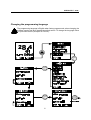
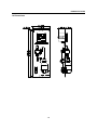
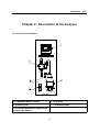
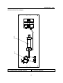
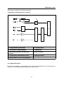
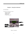
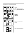
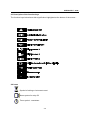
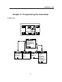
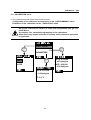
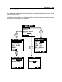
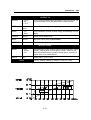
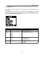
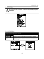
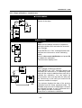
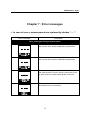
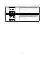
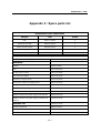
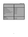
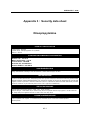
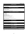
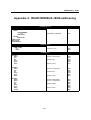
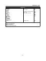
HYDRASTAT
- 9186 Instruction manual
03/2001
st
621=191=086
Rev. C
HYDRASTAT - 9186 -
This instrument conforms to the European Directives :
- 89/336/CEE modified by the directive 93/68/CEE
- 73/23/CEE modified by directive 93/68/CEE
Warning!
There are no user-serviceable parts in either the transmitter or sensor. Only Polymetron
personnel or their authorized representative should attempt repair of the system and only
components expressly approved by the manufacturer should be used. Any attempt to repair the
instrument in contradiction of these guidelines may result in damage to the instrument and injury to
the person making the repair. It will also void the warranty and may compromise the safe operation,
electrical integrity or CE compliance of the instrument.
HYDRASTAT - 9186
COPYRIGHT
All rights reserved. No part of this publication may be
reproduced, stored in a retrieval system, or
transmitted, in any form or by any means, electronic,
mechanical, photocopying, recording or otherwise,
without prior permission of Polymetron S.A.
Polymetron S.A.
Polymetron S.A. can take no
responsability for installation and/or use of its
equipment if this is not done in accordance with
the appropriate issue and/or amendment of the
relevant manual.
The user of this manual should ensure that it is
appropriate in all details to the exact equipment to
be installed and/or operated. If in doubt, the user
should contact Polymetron for advice.
WARNING
To maintain safety standards, regular maintenance,
calibration and operation of this equipment by
qualified personnel is essential. Read and understand
Instruction manual completely before operating or
servicing. If any further details are required which do
not appear in this manual contact Polymetron S.A. or
their agent.
HYDRASTAT - 9186-
Table of contents
Warning . . . . . . . . . . . . . . . . . . . . . . . . . . . . . . . . . . . . . . . . . . . . . . . . . . . . . . . . . . . . . . . . . . . . . . . . . . . iii
Chapter 1 : Introduction . . . . . . . . . . . . . . . . . . . . . . . . . . . . . . . . . . . . . . . . . . . . . . . . . . . . . . . . . . . .
1.1 Principle of operation . . . . . . . . . . . . . . . . . . . . . . . . . . . . . . . . . . . . . . . . . . . . . . . . . . . . . .
1.2 Main characteristics . . . . . . . . . . . . . . . . . . . . . . . . . . . . . . . . . . . . . . . . . . . . . . . . . . . . . . .
1.3 Technical characteristics . . . . . . . . . . . . . . . . . . . . . . . . . . . . . . . . . . . . . . . . . . . . . . . . . . .
1.4 Dimensions . . . . . . . . . . . . . . . . . . . . . . . . . . . . . . . . . . . . . . . . . . . . . . . . . . . . . . . . . . . . .
1-1
1-1
1-2
1-2
1-5
Chapter 2 : Description of the analyser . . . . . . . . . . . . . . . . . . . . . . . . . . . . . . . . . . . . . . . . . . . . . . .
2.1 Front side of the analyser . . . . . . . . . . . . . . . . . . . . . . . . . . . . . . . . . . . . . . . . . . . . . . . . . .
2.2 Back side of the analyser . . . . . . . . . . . . . . . . . . . . . . . . . . . . . . . . . . . . . . . . . . . . . . . . . .
2.3 Transmitter . . . . . . . . . . . . . . . . . . . . . . . . . . . . . . . . . . . . . . . . . . . . . . . . . . . . . . . . . . . . . .
2.3.1 Presentation of the transmitter . . . . . . . . . . . . . . . . . . . . . . . . . . . . . . . . . . . . . .
2.3.2 Application fields . . . . . . . . . . . . . . . . . . . . . . . . . . . . . . . . . . . . . . . . . . . . . . . . .
2-1
2-1
2-2
2-3
2-3
2-4
Chapter 3 : Installation of the instrument . . . . . . . . . . . . . . . . . . . . . . . . . . . . . . . . . . . . . . . . . . . . .
3.1 Unpacking . . . . . . . . . . . . . . . . . . . . . . . . . . . . . . . . . . . . . . . . . . . . . . . . . . . . . . . . . . . . . .
3.2 Inspection . . . . . . . . . . . . . . . . . . . . . . . . . . . . . . . . . . . . . . . . . . . . . . . . . . . . . . . . . . . . . . .
3.3 Mounting and connections . . . . . . . . . . . . . . . . . . . . . . . . . . . . . . . . . . . . . . . . . . . . . . . . .
3.4 Location . . . . . . . . . . . . . . . . . . . . . . . . . . . . . . . . . . . . . . . . . . . . . . . . . . . . . . . . . . . . . . . .
3.5 Hydraulic connections . . . . . . . . . . . . . . . . . . . . . . . . . . . . . . . . . . . . . . . . . . . . . . . . . . . . .
3.6 Electric connections . . . . . . . . . . . . . . . . . . . . . . . . . . . . . . . . . . . . . . . . . . . . . . . . . . . . . . .
3.7 Description of the different terminals . . . . . . . . . . . . . . . . . . . . . . . . . . . . . . . . . . . . . . . . .
3.8 Mains connection . . . . . . . . . . . . . . . . . . . . . . . . . . . . . . . . . . . . . . . . . . . . . . . . . . . . . . . . .
3.9 Starting the transmitter . . . . . . . . . . . . . . . . . . . . . . . . . . . . . . . . . . . . . . . . . . . . . . . . . . . .
3.10 Adjusting the display contrast . . . . . . . . . . . . . . . . . . . . . . . . . . . . . . . . . . . . . . . . . . . . . .
3-1
3-1
3-1
3-1
3-1
3-2
3-3
3-4
3-5
3-5
3-5
Chapter 4 :Using the instrument . . . . . . . . . . . . . . . . . . . . . . . . . . . . . . . . . . . . . . . . . . . . . . . . . . . . .
4.1 Front panel keys . . . . . . . . . . . . . . . . . . . . . . . . . . . . . . . . . . . . . . . . . . . . . . . . . . . . . . . . .
4.2 Display screens 1 to 4 (continuously refreshed) . . . . . . . . . . . . . . . . . . . . . . . . . . . . . . . .
4.3 Description of the function keys . . . . . . . . . . . . . . . . . . . . . . . . . . . . . . . . . . . . . . . . . . . . .
4.4 Icons . . . . . . . . . . . . . . . . . . . . . . . . . . . . . . . . . . . . . . . . . . . . . . . . . . . . . . . . . . . . . . . . . . .
4.5 Enter ou modify a value . . . . . . . . . . . . . . . . . . . . . . . . . . . . . . . . . . . . . . . . . . . . . . . . . . . .
4.6 Warnings . . . . . . . . . . . . . . . . . . . . . . . . . . . . . . . . . . . . . . . . . . . . . . . . . . . . . . . . . . . . . . .
4-1
4-1
4-2
4-3
4-3
4-4
4-4
Chapter 5 : Programming the transmitter . . . . . . . . . . . . . . . . . . . . . . . . . . . . . . . . . . . . . . . . . . . . .
5.1 Main menu . . . . . . . . . . . . . . . . . . . . . . . . . . . . . . . . . . . . . . . . . . . . . . . . . . . . . . . . . . . . . .
5.1.1 CALIBRATION Menu . . . . . . . . . . . . . . . . . . . . . . . . . . . . . . . . . . . . . . . . . . . . .
5.1.2 MAINTENANCE Menu . . . . . . . . . . . . . . . . . . . . . . . . . . . . . . . . . . . . . . . . . . . .
5.1.3 PROGRAMMING Menu . . . . . . . . . . . . . . . . . . . . . . . . . . . . . . . . . . . . . . . . . . .
5-1
5-1
5-2
5-3
5-3
i
HYDRASTAT - 91865.1.3.1 MEASURE Menu . . . . . . . . . . . . . . . . . . . . . . . . . . . . . . . . . . . . . . . . 5-4
5.1.3.2 ALARMS Menu . . . . . . . . . . . . . . . . . . . . . . . . . . . . . . . . . . . . . . . . . . 5-5
5.1.3.3 mA OUTPUTS Menu . . . . . . . . . . . . . . . . . . . . . . . . . . . . . . . . . . . . 5-7
5.1.3.4 RS485 Menu . . . . . . . . . . . . . . . . . . . . . . . . . . . . . . . . . . . . . . . . . . . 5-9
5.1.4 SERVICE Menu . . . . . . . . . . . . . . . . . . . . . . . . . . . . . . . . . . . . . . . . . . . . . . . . 5-11
5.1.4.1 AVERAGE Menu . . . . . . . . . . . . . . . . . . . . . . . . . . . . . . . . . . . . . . . 5-11
5.1.4.2 DISPLAY Menu . . . . . . . . . . . . . . . . . . . . . . . . . . . . . . . . . . . . . . . . 5-12
5.1.4.3 CODE Menu . . . . . . . . . . . . . . . . . . . . . . . . . . . . . . . . . . . . . . . . . . . 5-12
5.1.4.4 SOFT VERSION Menu . . . . . . . . . . . . . . . . . . . . . . . . . . . . . . . . . . 5-13
5.1.4.5 DEFAULT VAL. Menu . . . . . . . . . . . . . . . . . . . . . . . . . . . . . . . . . . . 5-14
5.1.4.6 mA ADJUST Menu . . . . . . . . . . . . . . . . . . . . . . . . . . . . . . . . . . . . . . 5-14
5.1.4.7 CONFIGURATION Menu . . . . . . . . . . . . . . . . . . . . . . . . . . . . . . . . . 5-15
5.1.4.8 POLYMETRON Menu . . . . . . . . . . . . . . . . . . . . . . . . . . . . . . . . . . . 5-15
Chapter 6 : Calibrating the instrument . . . . . . . . . . . . . . . . . . . . . . . . . . . . . . . . . . . . . . . . . . . . . . . .
6.1 Calibration of the temperature sensor . . . . . . . . . . . . . . . . . . . . . . . . . . . . . . . . . . . . . . . .
6.1.1 Automatic temperature compensation . . . . . . . . . . . . . . . . . . . . . . . . . . . . . . . .
6.1.2 Manual temperature compensation . . . . . . . . . . . . . . . . . . . . . . . . . . . . . . . . . .
6.2 Calibration of the measurement . . . . . . . . . . . . . . . . . . . . . . . . . . . . . . . . . . . . . . . . . . . . .
6.2.1 Slope calibration + electrical zero . . . . . . . . . . . . . . . . . . . . . . . . . . . . . . . . . . .
6.2.2 Slope calibration + chemical zero . . . . . . . . . . . . . . . . . . . . . . . . . . . . . . . . . . .
6-1
6-1
6-2
6-3
6-4
6-4
6-5
Chapter 7 : Error messages . . . . . . . . . . . . . . . . . . . . . . . . . . . . . . . . . . . . . . . . . . . . . . . . . . . . . . . . . 7-1
Appendix 1 : Default values . . . . . . . . . . . . . . . . . . . . . . . . . . . . . . . . . . . . . . . . . . . . . . . . . . . . . . . .
Appendix 2 : Spare-parts list . . . . . . . . . . . . . . . . . . . . . . . . . . . . . . . . . . . . . . . . . . . . . . . . . . . . . . .
Appendix 3 : Security data sheet . . . . . . . . . . . . . . . . . . . . . . . . . . . . . . . . . . . . . . . . . . . . . . . . . . .
Appendix 4 : RS485 MODBUS-JBUS addressing . . . . . . . . . . . . . . . . . . . . . . . . . . . . . . . . . . . . . .
ii
A1-1
A2-1
A3-1
A4-1
HYDRASTAT - 9186 -
Changing the programming language
The programming language is English when factory-programmed, when changing the
software version and when loading the default values. To change the language follow
the procedure below (example for French) :
iii
HYDRASTAT 9186
Chapter 1 : Introduction
1.1 Principle of operation
HYDRASTAT 9186 is an analyzer conceived to continuously measure the amount of
disolved hydrazine and other oxygen reducers in water. The measuring principle is based
on the electrochemical method of 3-electrod amperometry.
A polarization voltage (+480 mV) is applied between a platinum anode (working electrod)
and a stainless steel cathode (counter-electrode). Hydrazine is oxidized at the surface of
the platinum electrode - working electrode - and the resulting current is directly
proportional to the hydrazine concentration in the range of 0 to 500 ppb N2H4.
The reaction is enhanced in the alcaline environment, sample is conditioned at pH = 10,2
adding diethylamine or diisopropylamine through a Venturi tube, before the sample enters
the measuring cell. Compensation of the temperature effect is achieved through a
semiconductor sensor integrated to the measuring cell.
The chemical reaction is as follows :
(1)N2H4%4OH &YN2%4H2O%
%4e &
The anode-cathode torque potential is kept constant par rapport à/with respect to a third
electrode (reference electrode, Ag/AgCl). The system avoids interference effects resulting
from the variations of water composition that appear when using the 2-electrode system.
1-1
HYDRASTAT 9186
At +480 mV, the cell current is linearly proportional to the hydrazine concentration :
1.2 Main characteristics
3 Range
0-500 ppb hydrazine
0-100 ppb carbohydrazine
3 Automatic temperature compensation
3 Programmable alarm levels, outputs on relays
3 4-20 mA, 0-20 mA analogue outputs(standard) and RS485 (option)
1-2
HYDRASTAT 9186
1.3 Technical characteristics
SAMPLE
Number of channels
1
Temperature
5-45°C
Working pressure
0.5-6 bar (7~89 psi)
Flow
10 l/h < flow < 15 l/h - 12 l/h advised
ELECTRICAL CHARACTERISTICS
Mains
Ž Standard version :
100-240 VAC, 50/60 Hz
Ž Low voltage version :
13-30 VAC, 50/60 Hz
18-42 VDC
Maximum power consumption
25 VA
Connections
2.5 mm² screw terminal
Fuse
on cartridge
ANALYSIS
Measuring range
0-500 ppb dissolved N2H4
0-100 ppb carbohydrazine
Sensibility
< 0.2 ppb
Repeatability
< ± 2% of measurement or 1 ppb whichever is
greater
Detection limit
negligible
Response time (90 %)
< 60s
Ambient temperature
5-45BC / 41-113°F
Calibration
Electrical zero - set automatically, or with
hydrazine-free water, or with a chemical zero
cartridge (option)
Slope calibration by comparison with a laboratory
measurement
Temperature compensation
5-45°C (41-113°F)
TRANSMITTER
Display
Display in concentration units
Direct display of the concentration or cell current
in µA
Display of the sample temperature in BC/°F
Programming via menus
1-3
HYDRASTAT 9186
Analog outputs
800 Ohms maximum load
2 x 0/4-20 mA isolated from input signal,
- for measure or temperature
- mode : linear, bi-linear
- accuracy : 0.1 mA
Alarms
- Number : 4
- Functions : limit - system alarm - timer
- Hysteresis : 0-10%
- Delay : 0-999 s
- Breaking power : 250 VAC, 3A maximum
30 VDC, 0.5A maximum on a
resistive charge
RS485 (option)
Speed : 300-9600 bauds
Galvanically insulated
Number of stations : 32 maximum
Protocole : JBUS/MODBUS
transmitter protection
IP 65 (NEMA 4X in option)
Error reports
Cell current > 999 µA
Sample temperature > 45BC(113°F) or < 5BC
(41°F)
Slope calibration error
Zero calibration error (offset)
ELECTROMAGNETIC COMPATIBILY
Immunity against electromagnetic
interferences
EN 50082-2 and EN 50082-1
Electromagnetic emission
EN 50081-1 and EN 50081-2
Low voltage standard
IEC61010-1
MATERIALS
Working electrode
Platinum
Counter-electrode
Stainless steel
Reference
Ag/AgCl/KCl 0.1 M
Measuring cell
Acrylic
Transmitter
Aluminium + polyester painting
1-4
HYDRASTAT 9186
MAINTENANCE
Monthly maintenance
Ž filling in of the conditioning bottle
Ž Visual check of the filter or of the zero cartridge
Ž Visual check of the platinum electrode eventual deposit
Ž calibration
1-5
HYDRASTAT 9186
1.4 Dimensions
polymetron
polymetron
1-6
HYDRASTAT - 9186 -
Chapter 2 : Description of the analyser
2.1 Front side of the analyser
polymetron
polymetron
1 : Transmitter MONEC D9180
4 : Flow meter
2 : Measuring cell
5 : Conditioning bottle
3 : Activation/deactivation button of the
chemical zero (option)
2-1
HYDRASTAT - 9186 -
2.2 Back side of the analyzer
6 : Chemical zero cartridge (option)
7 : Pressure regulator
2-2
HYDRASTAT - 9186 -
2.3 Transmitter
2.3.1 Presentation of the transmitter
polymetron
The electronic unit amplifies the signal of the amperometric measuring cell and converts it into
a direct digital readout in ppm, mg/l, ppb, µg/l, BC and °F. The transmitter comprises the
following items :
# Potentiostat which maintains the working electrode potential constant
# Amperometric measuring module
# Analog multiplexer
# Microprocessor unit
Principle :
The analog multiplexer allows measurements to be acquired from the measuring cell,
temperature sensor and internal checkpoints. Further, the microprocessor operates the relays,
the RS485 interface (optional) and the analog outputs.
The unit has an automatic built-in concentration-autoranging feature and a microprocessoroperated calibration routine.
The output of the potentiostat is monitored for possible overdriving of the potentiostat-output
stage. This condition can occur with the connections to the measuring cell open, inoperable
2-3
HYDRASTAT - 9186 -
electrodes or a defective reference electrode.
Transmitter synoptic below is as follows :
1 : Programmable potentiostat
6 : Auxiliary input
2 : Polarization voltage amplifier
7 : Multiplexer
3 : Reversing switch for the electrode
operation
8 : A/D converter
4 : Temperature measurement circuit
9 : Microprocessor
5 : Measurement circuit current amplifier
2.3.2 Application fields
Easy-to-use (installation, programming), this instrument equipped with a microprocessor is
suitable for controlling hydrazine additions into boiler water.
2-4
HYDRASTAT - 9186 -
Chapter 3 : Installation of the instrument
3.1 Unpacking
3.3 Mounting and connections
The instrument only requires junction of
sample, cell reject and power supply.
The analyzer should be unpacked with great
care. Make sure not to loose any accesory
when unpacking.
CAUTION !
3.2 Inspection
Mounting should be done by
qualified service personnel only. No
power should be applied until the
installation is complete and
checked.
The analyzer has been factory-checked and
tested prior to shipment, it is however
advisable to inspect all parts immediately
upon receipt for any damage which may
have occured during shipment. A damaged
shipping container may indicate internal
damage which may not be immediately
obvious. If there is any evidence of damage,
keep the shipping container and refer to
your local agent or to :
3.4 Location
The analyzer should be located in a
accessible site.
The site should permit the access for any
checking or maintenance operation.
Polymetron S.A.
Z.I. des Richardets
33, rue du Ballon
93160 NOISY-LE-GRAND
3-1
HYDRASTAT - 9186 -
3.5 Hydraulic connections
A : 2 glands PG11
- Power supply
- Outputs (analog, RS485, alarms)
C : Sample output
B : 1 gland PG13
- Outputs (analog, RS485, alarms)
D : Sample input
3-2
HYDRASTAT - 9186 -
3.6 Electric connections
3 MONEC
Do not switch on the instrument until completion of the installation.
An aluminium shielding inside the MONEC gives a detailled description of the different terminals
and their connections to external elements :
Polymetron SA
L The different terminals represented on the right side are accessible by removing the
shielding.
P1 contrast adjustment
Relay board
Microprocessor board
RS485 board (option)
Programmed memory
Amperometric board
Power supply board
3-3
HYDRASTAT - 9186 -
3.7 Description of the different terminals
0/4-20 mA outputs
galvanically insulated
Description
Connection
0-20 mA or 4-20 mA (n°1) [+]
user
0-20 mA or 4-20 mA (n°1) [-]
user
0-20 mA or 4-20 mA (n°2) [-]
user
0-20 mA or 4-20 mA (n°2) [+]
user
option RS485
user
user
amperometric module
Description
Colour
Connection
temperature sensor [+]
black
temp +
temperature sensor [-]
blue
temp -
reference
transparent
ref
Counter electrode (anode)
grey
counter
Working electrode
(cathode)
white with
an orange
socket
work
Auxiliary input
not used
External shield
white+white
socket
shielding
Internal shield
white+white
socket
GND
Not used for the hydrazine measurement
n.c.
Mains, 100...240 VAC 50/60 Hz
or 24 V AC/DC (special version)
Descriptiion
connection
alarm 1, simple contact
user
alarm 2, simple contact
user
alarm 3 or system alarm, simple contact
user
alarm 4 or timer, simple contact
user
3-4
HYDRASTAT - 9186 -
L Electrical connections should remain dry to ensure a proper operation of the
instrument.
Check the creeping of the cables when opening the transmitter.
L It is required to use shielded cables. This shielding should be connected to the
central protective earth.
3.8 Mains connection
Electrical connection should be performed only by qualified personnel. The power supply
accepts 100-240 VAC ± 10 %, (50/60 Hz) without changes in configuration. The terminal block
for power connections can be lifted from its header for easier installation. For safety reasons,
it is required to observe the precautions below :
!
Use a three core mains supply cord (2 core + PE) rated for the maximum equipment
current
!
The instrument should be connected to the power supply by means of a breaker located
close to the instrument and be identified. The supply shall be fitted with an overcurrent
protection device rated at 20 Amp maximum
!
This breaker should switch off phase and neutral in case of electrical problems or when
the user wish to service the instrument. However the power supply earth must always
be connected.
Before servicing the instrument, ensure that the power supply is switched off.
3.9 Starting the transmitter
Before switching on the transmitter, make sure the site voltage corresponds to the instrument
voltage indicated on the identification plate.
3.10 Adjusting the display contrast
If the contrast on the display screen is not sufficient, you can adjust it with the potentiometer P1
(blue colour, see figure on page 3-3) which is located on the left top of the CPU board (after
opening the enclosure).
3-5
HYDRASTAT - 9186 -
Chapter 4 : Using the instrument
4.1 Front panel keys
The display may be programmed to indicate :
# Sample concentration
# Sample temperature
# Diffusion current
# Access codes
# Programming arguments
polymetron
Figure 4-1 : Front panel
4-1
HYDRASTAT - 9186 -
4.2 Display screens 1 to 4 (continuously refreshed)
28.4 µg/l : concentration measurement
(µg/l unit)
23.2°C : temperature measurement
O2Red : application
S1...S4 : alarm status (invisible if alarm
inactive).
Display of the measurement
parameters :
Concentration
Temperature
Cell current
S1...S4 : alarm status
In this case relays S1 and S3 are
activated.
Analog output assignment and level
4-2
HYDRASTAT - 9186 -
4.3 Description of the function keys
The function keys below have their signification highlighted at the bottom of the screen :
4.4 Icons
Symbol of waiting or instrument reset
Alarm system for relay S3
Timer symbol : countdown
4-3
HYDRASTAT - 9186 -
4.5 Enter or modify a value
The highlighted digit can be modified with the key
.
Each digit can be validated by pressing ENTER. Repeat both operations for each digit.
Example :
4.6 Warnings
Note 1 : If you do not use the keyboard for at least 10 minutes, the instrument returns to the
measuring mode.
Note 2 : An access code may be required for the calibration, programming and service
menu (see § CODE menu).
Possibility to display a negative first digit “-”
Possibility to display a “.” for the other digits.
4-4
HYDRASTAT - 9186
Chapter 5 : Programming the transmitter
5.1 Main menu
µg/l
13.2°C O2Red
CALIBRATION
MAINTENANCE
PROGRAMMING
SERVICE
CONC. CALIB.
TEMP. CALIB.
PARAMETERS
54.90 ppm
23.2°C
8.05 µA
MEASURE
ALARMS
mA OUTPUTS
RS485
5-1
AVERAGE
DISPLAY
CODE
SOFT ISSUE
DEFAULT VAL.
ADJUST mA
CONFIGURATION
POLYMETRON
HYDRASTAT - 9186
5.1.1 CALIBRATION menu
L Any calibration should follow the procedure below :
ì Configuration of the calibration characteristics in the “PROGRAMMING” menu.
í Realization of the calibration via the “EXECUTION” menu.
An access code may be required if it has been programmed (See §5.1.4.3
CODE Menu)
See chapter 6 for a detailled programming of the calibrations.
Some menus may appear in function of the way some parameters have been
programmed.
CONC. CALIB.
HISTORIC
PARAMETERS
ZERO
DATE: 07/12/98
P: 427.6µA/ppm
SLOPE
DATE: 01/01/98
P: 430.5µA/ppm
DATE: 01/01/98
P: 1.000µA/ppm
)T: 0.0 °C
5-2
HYDRASTAT - 9186
PARAMETERS
DATE
xx/xx/xx
Date of the previous calibration. The programmed
date is not automatically updated.
ZERO
XXXX nA
Offset value
P
x.xxx µA/ppm
Slope value
)T
x.x°C
Gap between the theoretical temperature (sensor
curve) Th and the temperature measured Tm :
)T = Th - Tm
HISTORIC : if there has not been any calibration, the window is empty
P
xxx.x µA/ppm
value of the penultimate calculated slope
P
xxx.x µA/ppm
value of the antepenultimate calculated slope
5.1.2 MAINTENANCE menu
Used for any maintenance operation in the instrument.
The transmitter continues to display the measured
variables.
The relay status is not modified.
The analog output value depends on the
configuration in the mA OUTPUTS/SPECIAL PROG.
/MAINTENANCE menu.
5-3
HYDRASTAT - 9186
5.1.3 PROGRAMMING menu
An access code may be required.(See § 5.1.4.3 CODE menu)
5-4
HYDRASTAT - 9186
51.3.1 MEASURE menu
TEMPERATURE COMPENSATION
TYPE
- Auto
- Manual
Choice of a temperature measurement with automatic
compensation or with a manual compensation
If you have chosen a manual temperature compensation, the TEMP.
CALIB. Menu is not accessible anymore.
TEMP.
- xx.x°C
Possibility to enter the sample temperature in a
manual compensation mode
5-5
HYDRASTAT - 9186
5.1.3.2 ALARMS menu
Relays S1...S4 may be assigned to the limit, alarm system or timer functions.
5LIMIT FUNCTION :
The alarm relays are activated if the comparison of the measured value with the programmed
limit meets the alarm function condition (up or down). Limits are programmed according to the
following programming variables :
ALARMS 1 .... 4 (LIMIT)
AFFECT
-Conc.
- no
-EC/EF
Use of a limit on the measure, on the
temperature or no use of a limit.
LIM
xxxx
Enter a limit value
DIR.
-Up
-Down
Choice of the direction
DELAY
xxxs
Temporisation time before the relay is
commutated (in seconds).
HYST.
XX%
Definition of the hysteresis limit in %
(10% max.)
The hysteresis operates only on one
side of the limit. The hysteresis is below
the limit for the up alarm and above the
limit for the down alarm.
RELAY
-NO
-NC
Relay normally open or normally closed
5-6
HYDRASTAT - 9186
5 ALARM SYSTEM FUNCTION :
The relay S3 can be used to indicate that the analyser has detected a faulty functioning.
It is required to connect the relay S3 to an external alarm system to control the faults traced by
the analyser.
The relay S3 is activated as soon as a default appears.
With manual acknowledgment, the relay remains activated even if the default disappears. Press
ENTER to disactivate the relay and the error message.
With automatic acknowledgment, the relay and the error message are desactivated as the
default disappears.
ALARM 3 (ALARM SYSTEM)
MODE
-No
-Limit
-Syst.
The alarm S3 may be programmed as a
limit function (See paragraph above) or as
an alarm system function
ACCEPT
-Auto
-Manu
In the case of an alarm system, choice
between a manual (key ENTER) or
automatic acknowledgment
RELAY
-NO
-NC
Choice of S3 normally open or normally
closed.
5-7
HYDRASTAT - 9186
5 TIMER FUNCTION :
Relay S4 may be affected to a timer function.
ALARM 4 (TIMER)
MODE
-No
-Limit
-Timer
Choice between a limit (see parameters
above) or a timer function for alarm 4.
INTERV
XXXXmn
Interval between 2 active cycles (in
minutes).
IMPUL.
X
Number of pulses during an active
cycle.
Ton
XXXs
Adjustment of the relay active time (in
seconds) for each pulse.
Toff
XXXs
Adjustment of the relay inactive time (in
seconds) for each pulse.
TmA
XXmn
Hold time for the analog outputs after
each cycle.
L The analog output status depends on the
configuration of the menu mA
OUTPUTS/SPECIAL PROG./TIMER
5-8
HYDRASTAT - 9186
5.1.3.3 mA OUTPUTS menu
The analog output signals allow the transmission of the measurements from the analyser to any
external control system.
It is highly recommended to use shielded cable for the output signals, connected to the earth
terminal on the shielding of the Hydrastat.
OUTPUT 1
OUTPUT 2
SPECIAL PROG.
TEST
MAINTENANCE
AFFECT.: µA
CALIBRATION
SYST. ALARM.
TIMER
TYPE : 4-20
MODE : Lin
LOW : 00001 nA
UP: 100.0 µA
MODE : Preset
VALUE : 00mA
VALUE : 00 mA
5-9
HYDRASTAT - 9186
OUTPUT 1/2
AFFECT
- Conc.
- µA
- EC/EF
Choice of the analog output allocation to the cell current, to
the concentration or to the temperature measurement.
TYPE
0/20
4/20
Choice of the analog output type
MODE
- Lin
- Dual
Choice between a linear or dual range (see drawing on next
page).
LOWER
XXXX
Bottom of the scale value
MIDD.
XXXX
Mid-scale value (only in dual mode)
UPPER
XXXX
Top of the scale value
SPECIAL PROG.
MODE
- last
- preset
- live
Characterictics of the analog output during calibration, alarm
system, maintenance or timer active cycles : frozen to the
latest stored before any operation listed above, forced to a
preset value, live measurement.
VALUE
XX
Preset value ( 0 to 21 mA)
TEST
Test the analog outputs by steps of 1 mA (0-21 mA)
5-10
HYDRASTAT - 9186
5.1.3.4 RS485 Menu
If the RS485 optional board is installed on your transmitter, program the parameters of the
menu below.
The RS485 optional board enables the connexion between your analyser and a digital
communication system. The Communication protocol is JBUS/MODBUS. Refer to the
instruction manual “JBUS/MODBUS communication” (part number : 621=991=000) for further
details and to Appendix 4 for the address list.
RS485
NE
XX
MONEC number (0-32)
BAUD
- 300
- 600
- 1200
- 2400
- 4800
- 9600
Transmission speed in baud
PARITY
- No
- Odd
- Even
Without parity bit
With odd parity bit
With even parity bit
BIT STOP
-1
-2
1 bit stop
2 bit stop
5-11
HYDRASTAT - 9186
5.1.4 SERVICE Menu
!
An access code may be required if it has been programmed (see §5.2.4.3
CODE Menu)
5.1.4.1 AVERAGE Menu
The measurement cycle lasts 4 seconds.
AVERAGENNE
AVERAGE
TEST
X
Program a moving average on the concentration measurement
Define the number of measurements to calculate the average.
Display the difference between a measurement obtained with and
without average.
5-12
HYDRASTAT - 9186
5.1.4.2 DISPLAY Menu
CONC : ppb/ppm
TEMP. : °C
LANGUAGE : F
DISPLAY
CONC
- ppb/ppm
- µg-mg/l
-%sat
Choice of the concentration unit
TEMP.
- EC
- EF
Choice of the temperature unit
LANGUAGE
-F
- GB
-D
- SP
-I
Choice of the language :
- French
- English
- German
- Spanish
- Italian
5.1.4.3 CODE Menu
Protection codes may be programmed to access the PROGRAMMING, CALIBRATION,
SERVICE menus.
This code may be desactivated by programming 0000.
CALIB. : 0000
PROG. : 0000
SERVICE : 0000
5-13
HYDRASTAT - 9186
CODE
CALIB.
XXXX
Access code to calibration
PROG.
XXXX
Access code to the “PROGRAMMING” menu
SERVICE
XXXX
Access code to the “SERVICE” menu
If you have forgotten your access code, press simultaneously ESC and ENTER to
enter the selected menu.
5.1.4.4 SOFT VERSION Menu
This menu displays the software version installed in the instrument.
5-14
HYDRASTAT - 9186
5.1.4.5 DEFAULT VAL. Menu
If you press YES, you load the default values and
you lose both the current programmed values and
calibration parameters.
5.1.4.6 mA ADJUST menu
The analog output signals are factory-adjusted (upper limit : 20mA). However if you discover
a drift of the 20 mA on one of the outputs, it is required to execute the menu below. Connect
an ammeter to the analog output terminals and adjust the value till you read 20.0 mA on the
amperemeter.
L The value displayed does not correspond to a mA value.
5.1.4.7 CONFIGURATION menu
You can program the mains supply frequency at 50 or 60Hz.
5-15
HYDRASTAT - 9186
5.1.4.8 POLYMETRON menu
This menu is reserved to POLYMETRON qualified
personnel.
5-16
HYDRASTAT - 9186 -
Chapter 6 : Calibrating the instrument
NOTE
See chapter 5 for programming the commands.
REMARK
Any result (calibration or measurement) is always brought back to the reference
temperature (25E
EC, 77E
EF). If the sample temperature is different from the reference
temperature, it is required to execute a temperature compensation which can be either
manual or automatic.
6.1. Calibration of the temperature sensor
The temperature sensor is located under the platinum anode. It is factory-preadjusted but
needs to be calibrated in the sample on site. This calibration must be realised before the
hydrazine measurement calibration (slope + zero).
6.1.1.Automatic temperature compensation
The sensor measures continuously the sample temperature. The concentration values are
automatically calculated in function of the reference temperature (25 EC) by a preprogrammed
compensation law in the transmitter.
6-1
HYDRASTAT - 9186 -
Follow the procedure below :
ì PROGRAMMING
Choice of an automatic temperature
compensation.
í EXECUTION
The execution is realised with the CALIBRATION
menu.
EXECUTION
21.2
21.2
°C
°C
21.2 °C
6.87ppm
Enter the sample temperature value in °C.
Press OK to adjust the temperature displayed to
the actual value of the sample temperature
measured with a precise thermometer.
The gap between the calibration and the
theoretical response curve of the sensor is given
for information.
)T: 0.0 °C
ENTER : ok
ESC : cancel
6-2
HYDRASTAT - 9186 -
6.1.2. Manual temperature compensation
This type of temperature compensation should be used only if your sample temperature is
constant.
ì PROGRAMMING
TEMP. COMP.
Choice of the manual temperature
compensation.
TYPE : Manual
Enter your sample temperature.
TYPE : Manual
TEMP.:25.0°C
í EXECUTION
Not applicable under a manual temperature
compensation mode.
6-3
HYDRASTAT - 9186 -
6.2. Calibration of the measurement
6.2.1. Slope calibration + electrical zero
ì PROGRAMMING
Choice of an electrical zero.
Note : the electrical zero is carried out
automatically by the transmitter at a regular
frequency.
í EXECUTION
Press ENTER, the “CAL” message flashes and
indicates the instrument is in calibrating mode.
Wait until the current is stabilized then press OK.
You can adjust the concentration value one digit
after the other with the function key to the value
you found with the reference method of analysis.
PROGRAMMATION
PROGRAMMING
EXECUTION
1.0
°ppm
25.0°C
0.00µA
DATE:01/01/98
P:
500 µA/ppm
The analyzer displays the date of the previous
calibration and the newly calculated slope. The
standard slope amounts to 500µA/ppm. However
the analiser accepts a value measured with ± 50%.
Modify the date if necessary.
Press Enter to validate the new calibration
parameters.
6-4
HYDRASTAT - 9186 -
6.2.2. Slope calibration + chemical zero
ì PROGRAMMING
Choice of the chemical zero
Choice of the slope
ZERO
SLOPE
PROGRAMMING
EXECUTION
TYPE : Chim.
í EXECUTION
ZERO :
Make sure the sample contains no hydrazine
pulling the button which activates the chemical
zero cartridge.
PROGRAMMING
EXECUTION
21.2
Press ENTER, the “CAL” message flashes and
indicates the instrument is under calibrating
mode.
Wait for the current stabilisation and press OK
to validate the calibration.
The instrument displays zero.
°ppm
25.0°C
5.693µA
0
°ppm
25.0°C
5.693µA
PROGRAMMING
PROGRAMMATION
EXECUTION
21.2
°ppm
25.0°C
5.693µA
DATE:01/01/98
P:
1nA/ppm
SLOPE :
Use a sample containing hydrazine.
Press ENTER, the “CAL” message flashes and
indicates the instrument is in calibrating mode.
Wait until the current is stabilized then press OK to
validate the calibration. You can adjust the
concentration value one digit after the other with
the function key to the value you found with the
reference method of analysis.
The analyzer displays the date of the previous
calibration and the newly calculated slope. The
standard slope amounts to 500µA/ppm. However
the analyzer accepts a value measured with ±
50%. Modify the date if necessary.
Press Enter to validate the calibration.
6-5
HYDRASTAT - 9186 -
Chapter 7 : Error messages
L In case of errors, measurements are replaced by dashes “- - -”.
Error messages
Description
Error messages during a measurement
The concentration value is out of the limits. Check
the current value and the calibration parameters.
The concentration value is out of the limits. Check
the current value and the calibration parameters.
The sample temperature is out of the limits. Check
the cable polarity. Check if there is any short-circuit
or open circuit, or water inside probe connector.
The current value is out of the limits. Check the
electrode and its connections.
7-1
HYDRASTAT - 9186 -
The current value is out of the limits. Check there is
no short-circuit on the measuring line. Check the
polarization voltage.
Error messages during a calibration
The temperature difference between the calibration
and the sensor theoretical response is superior to
the programmed limit.
Limits : ± 20°C
7-2
HYDRASTAT - 9186 -
Appendix 1 : Default values
CALIBRATION
CONC. CALIB.
OFFSET
Type : AutoElec.
PARAMETERS
DATE :01/01/98
ZERO : 0 nA
S : 0 nA/ppm
)T : 0.0 °C
PROGRAMMING
MEASURE
COMP. TEMP.
SENSOR : NTC
TYPE : Auto
ALARMS
ALARMS S1/S2/S4
AFFECT. : Conc.
LIM. : 0.00 ppb
DIR. : Low
DELAY : 000 s
HYST. : 00%
RELAY : NO
ALARM S3
AFFECT. : System
ACQUIT : Auto
RELAY : NF
mA OUTPUTS
OUTPUT 1
AFFECT. : Conc.
TYPE : 4-20
MODE : Lin.
LOW : 0.000 ppm
UP : 1.000 ppm
OUTPUT 2
AFFECT. : Conc.
TYPE : 4-20
MODE : Lin.
LOW : 0.000 ppm
UP : 1.000 ppm
SPECIAL PROG.
MAINTENANCE
MODE : memo
CALIBRATION
MODE : memo
TIMER
MODE : memo
ALARM SYSTEM
MODE : memo
A1-1
HYDRASTAT - 9186 -
RS485
No : 0
BAUD : 9600
PARITY : No
STOP BIT : 1
SERVICE
AVERAGE
AVERAGE : 1
DISPLAY
DISPLAY
CONC. : ppb/ppm
TEMP. : °C
LANGUAGE : GB
CODE
CODE
CALIB. : 0000
PROG. : 0000
SERVICE : 0000
CONFIGURATION
CONFIGURATION
FREQ. : 50 Hz
A1-2
HYDRASTAT - 9186 -
Appendix 2 : Spare parts list
Spare-parts kit for 2 years : 09186=A=8000
Description
Code
Quantity
Filter
363877,06000
6
Reference electrode
368429,00000
1
Venturi injection nozzle
359090,00024
1
Plastic cleaning beads
588801,75008
7
4 x 6 mm PE tubing
151575,00006
2m
Spare-parts list of the Hydrastat elements
Description
Code
TRANSMITTER
EPROM
09180=A=600
Fuse
295=100=6200
RS 485 board in option
09125=A=0485
CPU board with display
09125=A=1000
100-240 Vac supply board
09125=A=2000
13-30 Vac or 18-42 Vac supply board
09125=A=2020
Analog board for 9180
09180=A=1501
MONEC D9180 with software
09180=A=0100
MONEC D9180 (RS485) with software
09180=A=0111
MONEC D9180 (low tension supply) with software
09180=A=0120
MONEC D9180 (low tension supply + RS485) with
software
09180=A=0131
MEASURING CELL
09186=A=0100
Reference electrode
368429,00000
Working electrode
09186=A=0300
Raccord coudé entrée G1/8 DN 4/6
359103,10070
A2-1
HYDRASTAT - 9186 Raccord droit sortie G1/8 DN6/8
359103,10055
Bouchon NPT1/8
431=201=018
Conditioning bottle with equipment
09186=A=0200
Brown glass bottle
490=010=011
Porous cartridge
09073=C=0340
Raccord G1/8 DN4/6
359103,10065
Régulateur de pression équipé
09186=A=0400
Raccord droit entrée G1/4 DN4/6
587=006=002
Raccord coudé court intermédiaire G1/4 DN4/6
359103,10072
raccord coudé long sortie G1/4 DN4/6
587=906=002
Débitmètre
694=000=001
Raccord coudé NPT1/8 DN4/6
359103,10170
OPTION
Cartridge for chemical zero calibration
09186=A=0600
USER MANUAL
User manual in French
621=091=186
User manual in English
621=191=086
A2-2
HYDRASTAT - 9186 -
Appendix 3 : Security data sheet
Diisopropylamine
PRODUCT IDENTIFICATION
Product code : 803646
Product name : diisopropylamine for synthesis
FSD No : 30220
COMPOSITION/COMPONENTS INFORMATION
Numéro cas : 108-18-9
Masse moléculaire : 101.19
Formule brute : C6H15N
No-Index-CE : 612-048-00-5
Numéro EINECS : 203-558-5
DANGER IDENTIFICATION
Easily inflammable. Irritating in case of inhalation, contact with the eyes, the skin.
FIRST AID MEASURES
In case of contact with the skin, immediately flush with copious amounts of water while removing contaminated
clothing and shoes. Assure adequate flushing (for at least 10 minutes) of the eyes by separating the eyelids with
fingers. Consult a specialist. If inhaled, remove to fresh air. If swallowed, wash out mouth with water provided
person is conscious, try to make the person vomit. Call a physician immediately.
FIRE FIGHTING MEASURES
Appropriate extinguishing media : water, CO2, foam, powder.
Specific danger : combustible vapor heavier than the air. Explosive mixture may appear in contact with the
air. Keep away from ignition sources. In case of fire, Nox may form.
ACCIDENTAL RELEASE MEASURES
Use an absorbant for liquids - i.e. Chemizorb (R), Rhonesec (R) to collect the released product.
Wash spill site.
A3-1
HYDRASTAT - 9186 HANDLING AND STORAGE
Handling : no other specification
Storage :Stock the container hermetically closed in a cold, dry, air-sealed area. Take measures to avoid
electrostatic accumulation
EXPOSURE CONTROLS/PERSONAL PROTECTION
Respiratory system protection : necessary in case of vapor formation. Use a K filter (following DIN 3181) for
ammonia and aminated organic derivates.
Hands protection : necessary
Eyes protection : necessary
Industrial hygienic measure : take off any contaminated clothe.Preventive protection of the skin is
recommended. Wash your hands after handling.
PHYSICAL AND CHEMICAL PROPERTIES
Aspect : liquid
Color : colourless
Odor : amine-like
Ph : not applicable
Melting temperature : -96°C
Ebullition temperature : 83-84°C
Self-ignition temperature : 295°C - DIN 51794
Ignition point : -17°C - DIN 51755
Explosion limit in the air : lower : 1.5 vol%
Upper : 8.5 vol%
Vapour pressure : (20°C) 100 hPa
Density : (20°C) 0.72 g/cm3
Solubility in soluble water (20°C) / soluble organic solvents (20°C)
STABILITY AND REACTIVITY
Conditions to avoid : none
Materials to avoid : oxidants, acids
Other information : hygroscopic, sensitive to air
TOXICOLOGICAL INFORMATION
Acute toxicity : DL50 (if swallowed, [rat]) = 770 mg/kg
Other toxicological information : irritates the skin, the eyes, the mucous. Symptoms of exposure may include
coughing, shortness of breath. Danger of skin resorption.
ECOLOGICAL INFORMATION
Do not reject into natural water, waste water or on the ground.
DISPOSAL CONSIDERATIONS
Contact a licensed professional waste disposal service to dispose of this material.
The above information is believed to be correct but does not purport to be all inclusive and shall be used only as
a guide.
A3-2
HYDRASTAT - 9186 -
Appendix 4 : RS485 MODBUS-JBUS addressing
CALIBRATION menu
/CONC. CALIB.
/ZERO
/PROGRAMMING
/Type
/EXECUTION
/SLOPE
/EXECUTION
/TEMP. CALIB..
/EXECUTION
/PARAMETERS
(0:ElecAuto, 1:Chemical)
0121
MEASURE menu
/ TEMP. COMP.
/Type
/Temp.
(0:Manual,1:Auto)
1220
1230
ALARMS menu
/ALARM1
/Affect
/Lim.
/Dir.
/Delay
/Hyst.
/Relay
(0:conc, 1:°C/°F, 2:No)
(0:Low, 1:Up)
(0:N.O., 1:N.C.)
/ALARM2
/Affect
/Lim.
/Dir.
/Delay
/Hyst.
/Relay
(0:conc, 1:°C/°F, 2:No)
(0:Low, 1:Up)
(0:N.O., 1:N.C.)
/ALARM3
/Mode
/Affect
/Lim.
/Dir.
/Delay
/Hyst.
/Relay
/Accept
(0:Limit, 1:Syst, 2:No)
(0:conc, 1:°C/°F, 2:No)
(0:Bas, 1:Haut)
(0:N.O., 1:N.C.)
A4-1
2120
2130
2140
2150
2160
2170
2220
2230
2240
2250
2260
2270
2310
2320
2330
2340
2350
2360
2370
2380
HYDRASTAT - 9186 /ALARM4
/Mode
/Affect
/Lim.
/Dir.
/Delay
/Hyst.
/Relay
/Interv
/Impul.
/Ton
/Toff
/TmA
(0:Manu, 1:Auto)
(0:Limit, 1:Timer, 2:No)
(0:conc, 1:°C/°F, 2:No)
(0:Low, 1:Up)
(0;N.O., 1:N.C.)
2410
2420
2430
2440
2450
2460
2470
2401
2402
2403
2404
2405
mA OUTPUTS menu
/OUTPUT1
/Affect
/Type
/ Mode
/Low
/ Mid.
/Upp.
/OUTPUT2
/Affect
/Type
/Mode
/Low
/Mid.
/Upp.
/SPECIALPROG.
/MAINTENANCE
/Mode
/Value
/CALIBRATION
/Mode
/Value
/SYST. ALARM
/Mode
/Value
/TIMER
/Mode
/Value
/TEST
(0:µA, 1:°C/°F, 2.conc)
(0:0/20mA, 1:4/20mA)
(0:lin, 1:dual)
4110
4120
4150
4130
4160
4140
(0:µA, 1:°C/°F, 2:conc)
(0:0/20mA, 1:4/20mA)
(0:lin, 1:dual)
4210
4220
4250
4230
4260
4240
(0:Live, 1:Last, Preset)
4311
4312
(0:Live, 1:Last, 2:Preset)
4321
4322
(0:Live, 1:Last, 2:Preset)
4331
4332
(0:Live, 1:last, 2:Preset)
4341
4342
RS485 menu
/N°
/Baud
/Parity
/Stop bit
(0:300, 1:600, 2:1200, 3:2400,
4:4800, 5:9600)
(0:No, 1:Odd, 2:Even)
(0:1bit, 2:2bits)
A4-2
5100
5200
5300
5400
HYDRASTAT - 9186 SERVICE menu
/AVERAGE
/Average
/TEST
/DISPLAY
/Conc.
/Temp
/Language
/CODE
/Calib.
/Program
/Service
/SOFT ISSUE
/DEFAULT VAL.
/ADJUST mA
/OUTPUT1
/OUTPUT2
/CONFIGURATION
/Freq
(0:0,...10:10)
7210
(0:ppb-ppm, 1:µg-mg/l, 2:%sat.))
(0:°C, 1:°F)
(0;F, 1:GB, 2:D, 3:Sp, 4:I)
7360
7320
7330
7410
7420
7430
(0:60HZ, 1:50Hz)
Values measured :
Adr 0000 : concentration value
Adr 0002 : temperature value
Adr 0004 :current value
Adr 0006 : auxiliary measured value
A4-3
7810


![[PF03] User manual for WHITE-COLOR DOT - Auto](http://vs1.manualzilla.com/store/data/005728816_1-b07d7d3c2bb75a06da64907106241247-150x150.png)
![[PF03] User manual for RED DOT CLUSTERS(EN) - Auto](http://vs1.manualzilla.com/store/data/005713867_1-90b7ac4617a5dc924635c3e0ee039806-150x150.png)