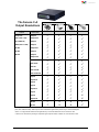
1
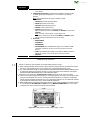
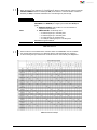
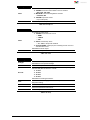
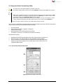
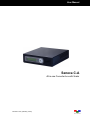
User Manual Seneca C-A All-in-one Converter box with Scaler Revision 1.0.0, (February, 2013) User Manual ABOUT THIS MANUAL This manual contains information on using the Avitech Seneca C-A all-in-one converter. There are two chapters in this manual. Getting Started, introduces the features and specifications as well as external components of Seneca C-A. System Configuration, discusses the steps on using the LCD panel to set up Avitech Seneca C-A, as well as using the proprietary Avitech ScreenCrop utility. Throughout the manual the following conventions are used to distinguish elements of text. provides additional hints or information that requires special attention. identifies warnings which must be strictly followed. Any name of a menu, command, icon or button on the screen is shown in a bold typeset. For example: On the Start menu select Settings. To assist us in making improvements to this user manual, we welcome any comments and constructive criticism. Email us at: [email protected]. WARNING Do not attempt to disassemble the Seneca all-in-one converter module. Doing so may void the warranty. There are no serviceable parts inside. Please refer all servicing to qualified personnel. TRADEMARKS All brands and product names are trademarks or registered trademarks of their respective companies. COPYRIGHT The information in this manual is subject to change without prior notice. No part of this document may be reproduced or transmitted in any form or by any means, electronic or mechanical for any purpose, without the express written permission of Avitech International Corporation. Avitech International Corporation may have patents, patent applications, trademarks, copyrights or other intellectual property rights covering the subject matter in this document. Except as expressly written by Avitech International Corporation, the furnishing of this document does not provide any license to patents, trademarks, copyrights or other intellectual property of Avitech International Corporation or any of its affiliates. TECHNICAL SUPPORT For any questions regarding the information provided in this guide, call our technical support help line at 425-885-3863, or our toll free help line at 1-877-AVI-TECH, or email us at [email protected] ii Contents About This Manual .................................................................................................................... ii Warranty.................................................................................................................................... iv Limitation of Liability ............................................................................................................... iv Extended Warranty Options.................................................................................................... iv Services and Repairs Outside the Warranty Period ............................................................. iv Regulatory Information ........................................................................................................... iv Federal Communications Commission (FCC) Statement .................................................... iv European Union CE Marking and Compliance Notices ....................................................... iv Australia and New Zealand C-Tick Marking and Compliance Notice ................................. iv 1. Getting Started ............................................................................................................ 1 1.1 1.2 1.3 1.4 Package Contents .............................................................................................................. 1 Product Features ............................................................................................................... 2 Specifications .................................................................................................................... 3 Connections to the Seneca C-A ....................................................................................... 6 2. System Configuration ................................................................................................. 8 2.1 Using the LCD Panel ......................................................................................................... 8 2.1.1 Welcome Screen ..................................................................................................... 8 2.1.2 Navigating the Main Menu ...................................................................................... 9 2.2 Using the Avitech ScreenCrop Utility ............................................................................ 15 2.2.1 ScreenCrop Utility Control Panel ........................................................................ 15 2.2.2 Using the ScreenCrop Utility ............................................................................... 17 2.2.3 Status Information ................................................................................................ 17 2.2.4 Cropping Feature .................................................................................................. 18 2.2.5 Cropped Instances Switching ............................................................................. 19 2.2.6 Pan Anywhere ....................................................................................................... 20 Appendix ........................................................................................................................ 21 Method 1: Change the IP Address of the Seneca C-A / C-HSS / C-SHS ............................ 21 Method 2: Change the IP Address of the Controlling Computer ....................................... 22 For Windows XP .............................................................................................................. 22 For Windows 7 ................................................................................................................. 22 Table of Output Resolutions .................................................................................................. 23 iii Warranty Regulatory Information Avitech International Corporation (herein after referred to as “Avitech”) warrants to the original purchaser of the products manufactured in its facility (the “Product”), that these products will be free from defects in material and workmanship for a period of 1 year or 15 months from the date of shipment of the Product to the purchaser. There is a 3 month grace period between shipping and installation. Marking labels located on the exterior of the device indicate regulations that the model complies with. Please check the marking labels on the device and refer to the corresponding statements in this chapter. Some notices apply to specific models only. Federal Communications Commission (FCC) Statement This equipment has been tested and found to comply with the limits for a Class A digital device, pursuant to Part 15 of the FCC Rules. These limits are designed to provide reasonable protection against harmful interference when the equipment is operated in a commercial environment. This equipment generates, uses, and can radiate radio frequency energy and, if not installed and used in accordance with the instruction manual, may cause harmful interference to radio communications. Operation of this equipment in a residential area is likely to cause harmful interference, in which case the user will be required to correct the interference at his own expense. Properly shielded and grounded cables and connectors must be used in order to meet FCC emission limits. Avitech is not responsible for any radio or television interference caused by using other than recommended cables and connectors or by unauthorized changes or modifications to this equipment. Unauthorized changes or modifications could void the user's authority to operate the equipment. Operation is subject to the following two conditions: (1) this device may not cause harmful interference, and (2) this device must accept any interference received, including interference that may cause undesired operation. If the Product proves to be defective during the 1 year warranty period, the purchaser’s exclusive remedy and Avitech’s sole obligation under this warranty is expressly limited, at Avitech’s sole option, to: (a) repairing the defective Product without charge for parts and labor; or (b) providing a replacement in exchange for the defective Product; or (c) if after a reasonable time is unable to correct the defect or provide a replacement Product in good working order, then the purchaser shall be entitled to recover damages subject to the limitation of liability set forth below. Limitation of Liability Avitech’s liability under this warranty shall not exceed the purchase price paid for the defective product. In no event shall Avitech be liable for any incidental, special, or consequential damages, including without limitation, loss of profits for any breach of this warranty. If Avitech replaces the defective Product with a replacement Product as provided under the terms of this Warranty, in no event will the term of the warranty on the replacement Product exceed the number of months remaining on the warranty covering the defective Product. Equipment manufactured by other suppliers and supplied by Avitech carries the respective manufacturer’s warranty. Avitech assumes no warranty responsibility either expressed or implied for equipment manufactured by others and supplied by Avitech. European Union CE Marking and Compliance Notices Statements of Compliance English This product follows the provisions of the European Directive 1999/5/EC. Dansk (Danish) This Warranty is in lieu of all other warranties expressed or implied, including without limitation, any implied warranty of merchantability or fitness for a particular purpose, all of which are expressly disclaimed. Dette produkt er i overensstemmelse med det europæiske direktiv 1999/5/EC. Nederlands (Dutch) Dit product is in navolging van de bepalingen van Europees Directief 1999/5/EC. This Hardware Warranty shall not apply to any defect, failure, or damage: (a) caused by improper use of the Product or inadequate maintenance and care of the Product; (b) resulting from attempts by other than Avitech representatives to install, repair, or service the Product; (c) caused by installation of the Product in a hostile operating environment or connection of the Product to incompatible equipment; or (d) caused by the modification of the Product or integration with other products when the effect of such modification or integration increases the time or difficulties of servicing the Product. Suomi (Finnish) Tämä tuote noudattaa EU-direktiivin 1999/5/EC määräyksiä. Français (French) Ce produit est conforme aux exigences de la Directive Européenne 1999/5/EC. Deutsch (German) Dieses Produkt entspricht den Bestimmungen der Europäischen Richtlinie 1999/5/EC. Any Product which fails under conditions other than those specifically covered by the Hardware Warranty, will be repaired at the price of parts and labor in effect at the time of repair. Such repairs are warranted for a period of 90 days from date of reshipment to customer. Ελληνικά (Greek) To προϊόν αυτό πληροί τις προβλέψεις της Ευρωπαϊκής Οδηγίας 1999/5/EC. Íslenska (Icelandic) Þessi vara stenst reglugerð Evrópska Efnahags Bandalagsins númer 1999/5/EC. Extended Warranty Options Avitech offers OPTIONAL Extended Warranty plans that provide continuous coverage for the Product after the expiration of the Warranty Period. Contact an Avitech sales representative for details on the options that are available for the Avitech equipment. Italiano (Italian) Questo prodotto è conforme alla Direttiva Europea 1999/5/EC. Norsk (Norwegian) Dette produktet er i henhold til bestemmelsene i det europeiske direktivet 1999/5/EC. Services and Repairs Outside the Warranty Period Avitech makes its best offer to repair a product that is outside the warranty period, provided the product has not reached its end of life (EOL). The minimum charge for such repair excluding shipping and handling is $200 (US dollars). Português (Portuguese) Este produto cumpre com as normas da Diretiva Européia 1999/5/EC. Español (Spanish) Este producto cumple con las normas del Directivo Europeo 1999/5/EC. AVITECH INTERNATIONAL CORPORATION ● 8655 154th Ave., NE Redmond, WA 98052 ● TOLL FREE 1 877 AVITECH ● PHONE 1 425 885 3863 ● FAX 1 425 885 4726 ● [email protected] ● http://avitechvideo.com Svenska (Swedish) Denna produkt har tillverkats i enlighet med EG-direktiv 1999/5/EC. Australia and New Zealand C-Tick Marking and Compliance Notice Statement of Compliance This product complies with Australia and New Zealand's standards for radio interference. iv 1. Getting Started The Seneca C-A all-in-one Converter box allows conversion of signal source from HDMI/DVI/VGA/ YPbPr/CVBS (NTSC/PAL) and SDI (3G/HD/SD) to HDMI/DVI/VGA and SDI (3G/HD/SD) output with scaling. A compact, stand-alone video converter, it is ideal for many professional video conversion applications, including video production, conferencing, presentation, OB vans, post-production, and television broadcasting. It provides automatic video input format detection, audio monitoring, supports a wide variety of video resolutions, and is capable of simultaneous output of VGA, DVI, HDMI, and SDI signals. This chapter introduces the features and specifications as well as external components of Avitech Seneca C-A. 1.1 Package Contents Avitech Seneca C-A Utility Disc (software and user manual) 12 V DC 2.5 A Power Adapter Magnetic Foot Stand with Screws (4 pcs) DVI-I to VGA Adapter D 1 DVI-I to YPbPr Adapter (optional) Rack mount kit (optional) D Table 1-1 Package Contents 1.2 Product Features The Seneca C-A is capable of converting and scaling signals to a high quality HDMI/DVI/VGA and SDI signals. It can sense the following input signals: HDMI/DVI/VGA/YPbPr/SDI(3G/HD/SD)/CVBS(NTSC/ PAL) automatically, then convert and scale it to the user-defined HDMI/DVI/VGA and SDI signal. The Seneca is capable of simultaneous output of DVI, HDMI, and SDI signals with most resolutions.* It also features a DVI-D LOOP OUT** port for connection of an external display for monitoring of the signal entering the DVI-I IN port. The Seneca C-A also supports area of interest cropping through its LCD interface and via a network connection. Additionally, Avitech’s ScreenCrop utility** can monitor the broadcast output of all networked Seneca devices and supports multiple instances of area of interest cropping on the Seneca C-A. For television broadcast application, the Seneca C-A supports set safe area graticules, genlock function (optional) with timing offset controls and analog stereo audio which can be embedded into the SDI/HDMI 1 output with delay. The Seneca has audio monitoring through an /8 inch stereo headphone jack (which supports up to 170ms of delay). The LCD interface on the Seneca C-A displays its operational status and input signal information. The LCD interface also allows users to fully configure all the Seneca’s settings. * See the Output Resolution Table in the Appendix of this manual for a complete list of resolutions. ** DVI-D loop out does not support analog source signals; VGA or YPbPr (through VGA or YPbPr to DVI adapter). *** Image/video crop, aspect ratio, output resolution, device name and IP address adjustments are also supported by the Avitech ScreenCrop. Note: To comply with HDCP license agreement, any source with HDCP will not be converted to SDI. 2 1.3 Specifications Input SDI/CVBS (BNC connector) HDMI (HDMI type A) DVI-I (DVI-I connector) VGA/YPbPr (via adapter) Genlock (BNC connector) Audio (Phono jack) Automatic sensing SDI (3G/HD/SD) CVBS (NTSC/PAL): NTSC/PAL SD-SDI (SMPTE 259M): 525i60, 625i50 HD-SDI (SMPTE 292M): 720p25, 720p29.97, 720p30, 720p50, 720p59.94, 720p60, 1080i50, 1080i59.94, 1080i60 3G-SDI (SMPTE 424M): 1080p23.98, 1080PsF24, 1080p25, 1080p29.97, 1080p30, 1080p50, 1080p59.94, 1080p60 Automatic sensing, the following input signals are supported: 640x480, 60Hz/75Hz 720×400, 70Hz 800x600, 50Hz/60Hz/75Hz 1024x768, 50Hz/60Hz/75Hz 1280x960, 50Hz/60Hz 1280x1024, 50Hz/60Hz/75Hz 1360x765, 50Hz/60Hz 1400x1080, 50Hz/60Hz 1600x1200, 50Hz/60Hz 1680x1050, 50Hz/60Hz 1920x1080, 50Hz/60Hz 1920x1200, 50Hz/60Hz Automatic sensing, the following input signals are supported: 640x480, 60Hz/75Hz 720×400, 70Hz 800x600, 50Hz/60Hz/75Hz 1024x768, 50Hz/60Hz/75Hz 1280x960, 50Hz/60Hz 1280x1024, 50Hz/60Hz/75Hz 1360x765, 50Hz/60Hz 1400x1080, 50Hz/60Hz 1600x1200, 50Hz/60Hz 1680x1050, 50Hz/60Hz 1920x1080, 50Hz/60Hz 1920x1200, 50Hz/60Hz Automatic sensing, via adapter in DVI-I IN port; input signals supported: 800x600, 50Hz/60Hz 1024x768, 50Hz/60Hz 1280x960, 50Hz/60Hz 1280x1024, 50Hz/60Hz 1360x765, 50Hz/60Hz 1400x1080, 50Hz/60Hz 1600x1200, 50Hz/60Hz 1680x1050, 50Hz/60Hz 1920x1080, 50Hz/60Hz 1920x1200, 50Hz/60Hz If the refresh rate is other than 60Hz, the image could become out of alignment. In the case, use the “VGA Adjustment” feature to realign. H START, V START, WIDTH, HEIGHT, and H TOTAL (through LCD interface). Frame synchronizer (Ref IN port) Note: For model without genlock feature, this port is not available Analog audio (AUDIO IN port, stereo) AES/EBU (embedded) 3 Input Ethernet (RJ45 connector) For using Avitech ScreenCrop utility or performing advanced operations (IP port) Output SDI (BNC connector) HDMI (HDMI type A) DVI-I (DVI-I connector) DVI-D Loopout (DVI-D connector) User Configurable (support SMPTE 259M, 292M, and 424M at YCbCr 4:2:2/4:4:4 or RGB 4:4:4, 10-bit): SD-SDI: 487i59.94, 576i50 HD-SDI: 720p23.98, 720p24, 720p25, 720p29.97, 720p30, 720p50, 720p59.94, 720p60, 1080i23.98PsF, 1080i24PsF, 1080i50, 1080i59.94, 1080i60 3G-SDI: 1080p23.98, 1080p24, 1080p25, 1080p29.97, 1080p30, 1080p50, 1080p59.94 1080p60 SDI Embedded Audio (SDI OUT port) Note: For models without the genlock feature (no Ref IN port); the following refresh rates are not supported 23.98, 29.97 and 59.94Hz. User selectable: 800x600, 50Hz/60Hz/75Hz 1024x768, 50Hz/60Hz/75Hz 1280x720, 50Hz/60Hz/75Hz 1280x768, 50Hz/60Hz/75Hz 1280x1024, 50Hz/60Hz/75Hz 1360x768, 50Hz/60Hz/75Hz 1400x1050, 50Hz/60Hz/75Hz 1440x900, 50Hz/60Hz/75Hz 1600x1200, 50Hz/60Hz/75Hz 1680x1050,50Hz/60Hz/75Hz 1920x1080, 50Hz/60Hz User selectable: 640x480, 60Hz 800x600, 50Hz/60Hz/75Hz 1024x768, 50Hz/60Hz/75Hz 1280x720, 50Hz/60Hz/75Hz 1280x768, 50Hz/60Hz/75Hz 1280x1024, 50Hz/60Hz/75Hz 1360x768, 50Hz/60Hz/75Hz 1400x1050, 50Hz/60Hz/75Hz 1440x900, 50Hz/60Hz/75Hz 1600x1200, 50Hz/60Hz/75Hz 1680x1050,50Hz/60Hz/75Hz 1920x1080, 50Hz/60Hz 1920x1200, 50Hz/60Hz Looping output of the DVI-I input (non-configurable and not available for VGA or YPbPr signal through DVI adapter): 640x480, 60Hz/75Hz 720×400, 70Hz 800x600, 50Hz/60Hz/75Hz 1024x768, 50Hz/60Hz/75Hz 1280x960, 50Hz/60Hz 1280x1024, 50Hz/60Hz/75Hz 1360x765, 50Hz/60Hz 1400x1080, 50Hz/60Hz 1600x1200, 50Hz/60Hz 1680x1050, 50Hz/60Hz 1920x1080, 50Hz/60Hz 1920x1200, 50Hz/60Hz 4 Output Audio (Headphone jack) Analog Audio (audio out port) Stereo Others Power Dimension/Weight Environment/ Safety Power consumption is 15 W maximum Power Supply: Input (AC): 100 to 250 V Output (DC): 12 V adapter Dimension, 174×172×43 mm (6.85×6.77×1.69 inch) Weight, 740 g (1.63 lb) Temperature: Operating: 0 C (32 F) to 40 C (104 F) Storage: –10 C (–4 F) to 50 C (122 F) Humidity, 0% to 80% relative, non-condensing Safety, FCC/CE/C-Tick/Class A Table 1-2 Specifications 5 1.4 Connections to the Seneca C-A Figure 1-1 Seneca C-A Components Front Panel LCD Panel Control Buttons System Fan For displaying the configuration and control parameters Go to previous selection Go to next selection Enter next menu level or select item Contains the system fan* Rear Panel Ethernet (IP) For controlling the Seneca C-A through a network connection. (use with Avitech’s ScreenCrop utility) Audio In/Out DVI-D LOOP OUT Ref IN SDI OUT DVI-I IN HDMI OUT HDMI IN DVI-I OUT SDI/CVBS IN Power (DC 12V) Connects to the green connector for headphone function (stereo) IN Connects to the pink connector for analog audio input DVI connector for DVI video out loop (output signal coming from DVI-I IN port only)** Note: Often used for preview when the connected desktop computer is only capable of supporting a single display output Multi-format sync reference input (YPbPr/NTSC/PAL) for genlock function (frame synchronizer) Note: For models without the genlock feature, this port is not available. BNC connector supports SDI (3G/HD/SD) signal output DVI connector for DVI/VGA/YPbPr input sources (a DVI to VGA adapter or DVI to YPbPr adapter may be required) Connect to the monitor’s HDMI signal cable*** HDMI connector for HDMI input source**** Connect to the monitor’s DVI/VGA (via adapter) signal cable BNC connector for SDI (3G/HD/SD) CVBS (NTSC/PAL) video input sources Connects to the 12 V DC power adapter Table 1-3 Seneca C-A Component Description 6 * Do not cover or block the ventilation openings. ** DVI-D loop out does not support analog source signals; VGA or YPbPr (through VGA or YPbPr to DVI adapter). *** Embedded audio is not available with the following input formats. 1. YCbCr 4:4:4 – 1080p(24/23.98)PsF and 720p(30/29.97)Hz 2. RGB 4:4:4 – 1080p(24/23.98)PsF and 720p(30/29.97)Hz **** To comply with HDCP license agreement, any source with HDCP will not be converted to SDI. 7 2. System Configuration This chapter discusses the process of using the LCD panel to set up Seneca C-A, as well as using the Avitech ScreenCrop utility. 2.1 Using the LCD Panel The LCD panel allows for control of the Seneca C-A including; input/output signal adjustment, video crop, keying/overlay, aspect ratio adjustment and operational status report. The LCD panel consists of 3 buttons: Go to previous selection (up arrow button) Go to next selection (down arrow button) Enter the next level of a menu, or select the currently highlighted item. Figure 2-1 LCD Panel: Busy State 1. 2. When the busy state “PLEASE WAIT . . . .” message is displayed on the LCD panel (see sample screen above), DO NOT disconnect or connect any signal cables as, a fault may occur. Also, DO NOT change any of the incoming signal’s display resolutions while the Seneca C-A is in the busy state. 2.1.1 Welcome Screen Upon starting up the LCD panel, the welcome screen is shown for about 15 seconds. Figure 2-2 LCD Panel: Welcome Screen Then the following default screen is displayed. Figure 2-3 LCD Panel: Default Initial Screen This screen displays the unit’s default settings. 1. First line (video): AUTOmatically selects the input signal in the following order (firstly CVBS, SDI, YPbPr, VGA, DVI, and lastly HDMI) when more than one signal type is detected. Then, outputs it at 1080P @ 60Hz. Note: Due to the screen display size constraint, (A:AUTO, H:HDMI, V:VGA, Y:YPbPr, S:SDI, D:DVI). 2. Second line (audio): The default audio signal source is set at “Follow Video” (e.g., HDMI). The audio feature allows the selection of audio signal source (Follow Video, HDMI, SDI, LINE IN). By default the audio delay is set to: 0 (no audio delay) the Seneca supports up 170ms of delay. Settings made through the LCD panel will be saved automatically upon turning off power to the Seneca. 8 2.1.2 Navigating the Main Menu 1. Press the button from the default initial screen to enter the main menu. 2. Use the buttons on the front panel to navigate: ( / / ) 3. The following sections are setup items on the main menu, details of each are in the following tables, respectively: Input Port Autoscan Exit On: enable the signal automatic detection feature. Off: select the signal manually. Source: HDMI DVI VGA YPbPr SDI Exit the input signal setup menu. Table 2-1 Input Port Make sure to select the correct signal type based on actual connected input signal to Seneca C-A to avoid image display problems (e.g., noise, flicker, etc.). Output Port SDI Standard Output Timing Exit On: enable the SDI out feature. Off: disable the SDI out feature. SMPTE: select this for SDI output. VESA: select this for HDMI/DVI/VGA output. For SMPTE standard, select the following output signal. 1080p @ 23.98, 24, 25, 29.97, 30, 50, 59.94, 60 (Hz) 1080i @ 23.98 PsF, 24 PsF, 50, 59.94, 60 (Hz) 720p @ 23.98, 24, 25, 29.97, 30, 50, 59.94, 60 (Hz) SD_625 (576i @ 50 Hz) SD_525 (487i @ 59.94 Hz) For VESA standard, select the following output signal. 1920x1200 @ 50, 60 (Hz) 1920x1080 @ 50, 60 (Hz) 1680x1050 @ 50, 60, 75 (Hz) 1600x1200 @ 50, 60, 75 (Hz) 1440x900 @ 50, 60, 75 (Hz) 1400x1050 @ 50, 60, 75 (Hz) 1360x768 @ 50, 60, 75 (Hz) 1280x1024 @ 50, 60, 75 (Hz) 1280x768 @ 50, 60, 75 (Hz) 1280x720 @ 50, 60, 75 (Hz) 1024x768 @ 50, 60, 75 (Hz) 800x600 @ 50, 60, 75 (Hz) 640x480 @ 60 (Hz) Note: For models without the genlock feature (no Ref IN port); 23.98, 29.97 and 59.94Hz refresh rates are not supported. Exit the output signal setup menu. Table 2-2 Output Port 9 Map Structure Select the desired “sampling structure/pixel depth” based on output signal’s “image format” and “frame/field rate.” YCbCr422 YCbCr444 RGB444 Exit the map structure setup menu. Status Exit Table 2-3 Map Structure 1. 2. 3. Embedded audio is not available with the YCbCr444 and RGB444 output formats. Map structure is not available when “OUTPUT PORT””STANDARD” is set at “VESA.” Map structure is locked at YCbCr422 when output resolution is at SD_525, SD_625, 1080p@50, [email protected], 1080p@60 (Hz). OSD (on screen display) Color Bar Exit On: enable the color bar and pattern select feature. The color bar can only be turned on when there is no input signal (default setting is OFF). COLOR BAR 2×2 CROSSHATCH Off: disable the display of the color bar. Exit the OSD setup menu. Table 2-4 OSD 1. 2. The COLOR BAR settings are not saved. The color bar feature is a pattern generator for showing a signal when there is no source. It can be utilized as test pattern (input signal) for self testing or other devices verification. Image Adjustment The input port currently selected is displayed as follows, (Input Port: VGA, Input Port: CVBS, etc.) If the selected input is digital such as SDI, DVI, or HDMI then this portion of image adjustment menu is not available. With digital signals use the (Image Adjustment / Parameter) portion of the menu. When the selected input signal is VGA, CVBS, or YPbPr, the following image adjustment settings are available. Status Auto-detect (firstly CVBS, SDI, YPbPr, VGA, DVI, and lastly HDMI) VGA Adjustment: this feature was designed to adjust analog VGA signal with misalignment or color-off due to long cabling situation. Note: Only available when the signal is VGA. DEFAULT HSTART (horizontal starting position) WIDTH (horizontal “active area”) VSTART (vertical starting position) HEIGHT (vertical “active area”) HTOTAL (horizontal total) ****(refer figure 2-4) Make sure that the values of HSTART plus WIDTH do not exceed HTOTAL. Note: V TOTAL: (vertical total) ****(refer figure 2-4) This value is based on the values of VSTART plus HEIGHT. (Must not exceed the pre-determined value for V Total). REDGAIN GREENGAIN BLUEGAIN AUTO ADJUST (performs automatic alignment of VGA image inside the window) 10 Image Adjustment Exit AUTO GAIN (performs automatic gain adjustment by correcting the color values) CVBS/YPbPr Adjustment: this feature was designed to adjust CVBS or YPbPr signal with misalignment or color-off due to long cabling situation. Note: Only available when the signal is CVBS or YPbPr. DEFAULT HSTART (horizontal starting position) WIDTH (horizontal “active area”) VSTART (vertical starting position) HEIGHT (vertical “active area”) HTOTAL (horizontal total) ****(refer figure 2-4) Make sure that the values of H START plus WIDTH do not exceed HTOTAL. Note: V TOTAL: (vertical total) ****(refer figure 2-4) This value is based on the values of VSTART plus HEIGHT. (Must not exceed the pre-determined value for V Total). Parameter: BRIGHTNESS CONTRAST SHARPNESS SATURATION (Only available when signal is non-RGB; or HDMI YCbCr422 / interlaced. In short, it can only be set for YUV color space.) HUE (only available when signal is non-RGB; or HDMI YCbCr422 / interlaced. In short, it can only be set for YUV color space.) DEFAULT Exit the image adjustment setup menu. Table 2-5 Image Adjustment 1. Image misalignment is most likely to occur for VGA signal in the 50Hz timing frequency range as well as the not so commonly used resolution in the 60Hz timing frequency range. a) When switching between VGA resolution signals that have timing frequency (horizontal and vertical frequency, vertical total) that are very near each other, image misalignment may occur. b) e.g., 1280×1024 60Hz change to 1400×1050 60Hz (adjust HSTART/VSTART/WIDTH/HEIGHT) back to 1280×1024 60Hz (since the timing frequency is very near that of 1400×1050 60Hz, then adjust HSTART/VSTART/WIDTH/HEIGHT for 1280×1024 60Hz again). 2. Depending on the signal type, SATURATION and HUE can only be set for YUV color space. a) YUV is a color space typically used as part of a color image pipeline. It encodes a color image or video taking human perception into account, allowing reduced bandwidth for chrominance components, thereby typically enabling transmission errors or compression artifacts to be more efficiently masked by the human perception than using a "direct" RGB-representation. b) When HDMI signal is transmitting under YCbCr422 color space (set from HDMI device itself), Seneca C-A will enable the SATURATION and HUE function in IMAGE PARAMETER menu. If it is under YCbCr444 color space, the above functions will be disabled. Figure 2-4 H-Start, Width, H-Total, V-Start, Height, V-Total 11 Crop Image Status Exit On: adjust the crop area and location. LEFT: set the horizontal starting point. TOP: set the vertical starting point. RIGHT: set the horizontal ending point. BOTTOM: set the vertical ending point. DEFAULT Off: disable the crop image feature. Exit the crop image setup menu. Table 2-6 Crop Image 1. 2. This feature will be OFF when KEYING feature is enabled. Make sure the difference in value for LEFT compared to the RIGHT is not less than 20% (e.g., LEFT = 80.0% RIGHT = 100.0%). Likewise, the difference in value for TOP compared to the BOTTOM must not be less than 20% (e.g., TOP = 80.0% BOTTOM = 100.0%). To put it simply, the smallest valid crop size is 20% the total height by 20% the total width. Aspect Ratio Status Exit On: set the display’s aspect ratio. 4:3 16:9 AUTO CUSTOM 1 to 20 for width ratio : 1 to 20 for height ratio. Off: disable the aspect ratio detect feature. Exit the aspect ratio setup menu. Table 2-7 Aspect Ratio 1. 2. 3. This feature will be OFF when KEYING feature is enabled. When the width is greater than the height, then the width must be less than 6 times the value of the height. (6:1 ratio) Likewise, when the height is greater than the width, then the height must be less than 6 times the value of the width. (1:6 ratio) Keying (Overlay) Status Exit On: superimpose the inputted computer image on top of an existing video signal. This feature works best with green screens and virtual sets. CROP IMAGE: set the crop area parameters. OUTPUT WINDOW: set output video range. BACKGROUND COLOR: set background color range (RGB) DEFAULT Off: disable the keying feature. Exit the keying setup menu. Table 2-8 Keying 1. 2. This feature will be OFF when CROP IMAGE or ASPECT RATIO feature is enabled. Make sure that KEYING is disabled (OFF) before running the Avitech ScreenCrop utility. Color Correct(ion) Status Exit On: enable the color correction feature. Off: disable the color correction feature. Exit the color correction setup menu. Table 2-9 Color Correction 12 1. 2. This function is applicable for 1080p input signal only. When the Seneca C-A (SDI OUT) is connected to the Seneca C-SHS (SDI IN), make sure that the COLOR CORRECT function is enabled (set ON) in the Seneca C-A and the Seneca C-SHS’s is disabled (set OFF) to allow the embedded color corrected signal to pass through. Genlock Status Exit On: this feature in Seneca C-A synchronizes the video sources (DVI-I IN, SDI/CVBS IN, and HDMI IN port’s signal synchronized with Ref IN port signal). GENLOCK OUTPUT: refer to table 2-11 for more details on supported output standard. TIMING OFFSET: set the delay lines. for SD 525 signal up to 524 delay lines for SD 625 signal up to 624 delay lines for 720p signal up to 749 delay lines for 1080p or 1080i signal up to 1124 delay lines Off: disable the genlock feature. Exit the genlock setup menu. Table 2-10 Genlock 1. 2. 3. For models without the genlock feature, this item is not available for setting. Genlock feature is not available when “OUTPUT PORT””STANDARD” is set at “VESA.” The genlock feature requires a sync reference signal to enter the Ref IN port. Changing, or disconnecting the sync reference will cause the Seneca to automatically turn off genlock. Table 2-11 Genlock Output 13 Headphone Enable: listen to the audio output via headphones. SOURCE: select from the available 4 source channels. CH1, CH2, CH3, CH4 MIX MODE: select the left/right/both channels. LCH, RCH, R/L VOLUME: adjust the volume. 1 up to 127 (level). Exit the headphone setup menu. Status Exit Table 2-12 Headphone Audio On: enable the audio output. SOURCE: select the audio source. HDMI LINE IN SDI DELAY: set the delay times. 0 to 170ms, sample rate at 48kHz. FOLLOW VIDEO: enable (On) auto switching of audio source to selected video source. Off: disable the audio output. Exit the audio setup menu. Status Exit Table 2-13 Audio Setup Backlight Contrast Idle Time Reset BIOS Version IP Address Exit On: enable the LCD panel's backlight. Off: disable the LCD panel's backlight. To set the LCD panel's contrast from 0 to 16. On: scrolling text (conversion format and related frame rate) will appear when the LCD panel of Seneca C-A is idle. 15 mins 30 mins 45 mins 60 mins Off: disable the scrolling text feature. On: reset to default setting, system reboot is required. Off: present setting. Show the current firmware version for reference. Allow user to modify the IP ADDRESS, SUBNET MASK, and GATEWAY based on their Ethernet environment. Exit the setup menu. Table 2-14 Setup 14 2.2 Using the Avitech ScreenCrop Utility 1. 2. This utility can be used with the Windows operating system only. This utility’s cropping feature cannot be used when KEYING is enabled (status: ON) in the LCD panel. For ScreenCrop to display correctly: 1. 2. When using a computer that does not support dual displays, make sure to use a DVI cable (or a HDMI ® cable with a HDMI-to-DVI adapter) to allow the signal to enter DVI-I IN port of Seneca. Then connect the external monitor to the DVI-D LOOP OUT port of the Seneca. When using a computer with a built in monitor such as; (a laptop, or an all-in-one computer) or when using a computer that supports dual display outputs* then you can connect via the HDMI IN port. * One of the outputs connects to Seneca C-A and the other connects to monitor. The Seneca C-A comes with a windows based user interface called ScreenCrop. Avitech’s ScreenCrop utility is intuitive and hosts several powerful tools including: Live Pan Preview Area of Interest Cropping. (supports 2 instances) Cropped-area scaling Easy adjustment of the output resolution and timing The ability to control up to 153 Seneca’s via network connection With ScreenCrop utility: Get Microsoft PowerPoint presentations and other computer-based content to air. Select and scale a YouTube window to fit any broadcast output resolution. Crop out extraneous interface toolbars and broadcast clean Google Earth maps. Output any video stream playing on any media player such as; QuickTime, VLC, or Windows Media Player. 2.2.1 ScreenCrop Utility Control Panel Figure 2-5 ScreenCrop Utility Control Panel 15 Status Information (1) Display all detected Avitech Seneca Converters in the same network mask. The status button will become active (not grayed-out) when Seneca C-A / C-HSS / C-SHS is selected from the Devices on Network window. Devices on Network Click IP list refresh button to update the connected Avitech devices’ IP addresses in the same network mask. Change the IP address of selected Seneca C-A / C-HSS / C-SHS. IP List Refresh Button Change IP Status Button View the selected Seneca C-A / C-HSS / C-SHS operational status. C-A / C-HSS / C-SHS Output Resolution This displays what type of Seneca converter is currently connected. For configuring the specific output resolution and related frame rate. Cropping Feature (2) Left/Top/Width/ Height Set Instance Switch Instance Ratio Crop Auto Select Repeated Pan Send Crop Disable Crop Display and adjust the cropped instance’s size and related location. After entering/adjusting the Left/Top/Width/Height parameters, click this button to update the location of the four green cropping corners. Select between two different area of interest instances (Instance One or Two) and then set the cropping parameters. If both Instance One and Instance Two cropping parameters have been set, then clicking the Switch Instance button will toggle between the two instances and automatically output the cropping parameters. Select a fixed (1:1, 3:2, 4:3, 5:4, 16:9) aspect ratio or non-fixed (Any) aspect ratio for the area of interest selector. Click this button and drag the cursor to crop an area. Upon releasing left mouse button, four green cropping corners are displayed signifying the area just selected (area of interest). Automatically select a window/object to be cropped by positioning the Crosshair on the desired window/object. For example, auto-select a YouTube window or a Google Map. Enable the pan feature for cropped instance (pan anywhere). Send the cropped instance to selected Seneca C-A. Disable the cropping. Cropping feature is only available on Seneca C-A / C-HSS. Others (3) Save to Flash Disconnect Save the current ScreenCrop session’s parameter to flash memory of Seneca C-A. The settings can be automatically loaded on next ScreenCrop session. Terminate the connection of selected Seneca C-A / C-HSS / C-SHS. Table 2-15 ScreenCrop Utility Control Panel Description The Seneca C-A’s sister device, the Seneca C-SHS, has different features and only has limited support of the ScreenCrop utility. It only supports: status, change output resolution and change IP. 16 2.2.2 Using the ScreenCrop Utility Before using the ScreenCrop utility to control Seneca C-A, it needs to be set in the same network mask with the connected computer. Please refer to the “Appendix” for further details on setting up the network mask. To use the ScreenCrop utility, perform the following steps: Step 1. Copy the three ScreenCrop utility system files to the computer. Step 2. Double-click ScreenCrop.exe. In case an alert screen appears, click Unblock to continue. Windows Security Alert screen may appear upon using ScreenCrop utility for the first time on the computer. Click Unblock, and the Windows Alert will not appear on subsequent uses of ScreenCrop. 2.2.3 Status Information ScreenCrop utility allows for easy monitoring of all networked Seneca devices. With 2 clicks of the mouse you can have the operational status of any of the Seneca converters that are on your network. Step 1. Click to select the desired IP address from the Devices on Network window. This will connect you to that particular Seneca device. The “Status” button will be enabled and the radio button for Seneca C-A or Seneca C-HSS or Seneca C-SHS would be faintly highlighted. Step 2. Click the “Status” button and a popup window will display detailed information about that device’s operational status and broadcast output. Display the Seneca converter’s status information such as input signal type, output resolution and related frame rate, audio source, color correction on/off, sampling, pixel depth, genlock on/off (optional); and input timing such as horizontal/vertical frequency, vertical total lines, horizontal total/start pixel, and vertical start line. Figure 2-6 Detailed Information of Connected Seneca C-A 17 2.2.4 Cropping Feature ScreenCrop utility allows the setting of 2 instances of an “area of interest” which can then transmit the associated contents to the intended audiences. For area of interest cropping perform the following steps. Step 1. Click the Crop button and use the cursor to select an area to crop. Upon releasing left mouse button, four green cropping corners are displayed signifying the area just selected. A floating 5× magnifying window shows any nearby graphics at 5x and relevant cursor information (e.g., position and RGB value). Figure 2-7 Magnified Floating Window Showing Cursor and RGB Value Drag on any of the four green cropping corners to enlarge/reduce the area just selected. Or, use the keyboard’s top/left/right/down buttons to fine-tune the scope of the area to be cropped without lifting the mouse button. For fine tuning, enter the values of the Left/Top/Width/Height manually and click the Set button. This will modify the scope of area to be cropped with pixel level accuracy. 1. When cropping, the Left/Top position, Width, and Height are calculated based on the module’s input display size. The value for Width and Height must be greater than 20% of the panel width and panel height. For example, if the module’s input display timing is 1280×1024 @ 60Hz, then the panel width is 1280 and the panel height is 1024. The cropped window size must be greater than 256 (20% of 1280) × 204 (20% of 1024). 2. Depending on the display resolution, a minimal change in the cropping parameters (Left/Top/Width/ Height) might not produce any noticeable effect. It is highly recommended to set the displayed image to fill up the whole screen of monitor to prevent black bar(s) from appearing after cropping. 3. Step 2. Then click the Send Crop button to send the cropped image to the Seneca C-A to be displayed from all of its outputs except the DVI Loop Out. Due to the image scaling method of the different graphics cards in the market, a pixel or more of any of the four green corner’s residue may be left on the screen. Adjust the value of Left/Top/Width/Height, and then click the Set button to fine-tune the display area so that the four green corner’s residue will disappear. Automatically select a window or object to be cropped by clicking and dragging the crosshair button and then positioning it on desired window/object to be cropped. Notice how the mouse cursor has become a crosshair. As you continue to hold the mouse button depressed and move around the screen, four green corners as well as a violet rectangle would encompass the selected window/object. When the desired window has been selected, release the left mouse button. 18 To create another screen crop, perform the steps again. To discard the just selected area, click the Disable Crop button. Step 3. To disconnect the computer from the Seneca C-A / C-HSS / C-SHS, click the Disconnect button. Or, close the ScreenCrop utility. 1. 2. Upon quitting ScreenCrop utility, the last crop parameters (Left/Top/Width/Height) which were stored either via: “Saved to Flash” button or “Send Crop” button will automatically be shown upon next start-up of the utility. Upon restarting ScreenCrop utility and if the present screen resolution is different compared to resolution of last saved crop parameters, then the crop parameters will need to be adjusted based on the new resolution. 2.2.5 Cropped Instances Switching ScreenCrop utility not only provides area of interest cropping but also allows selection of two different instances which can be switched accordingly when desired. Perform the following steps for switching between two cropped instances. Step 1. Use the drop-down menu to select Instance One or Two, and then set the cropping parameters. Step 2. Switch between the two “Instances” by clicking the Switch Instance button. Figure 2-8 Area of Interest (First/Second Instance) 19 2.2.6 Pan Anywhere The “Pan” feature allows transfer of previously set crop area of interest to another portion of screen by clicking Repeated Pan button. Upon clicking the Repeated Pan button, the following dialog box will appear. Figure 2-9 Pan Instruction Follow the instruction in the dialog box by placing the mouse pointer on any of the four cropping corners, and then use the right-mouse button to pan the crop area. Figure 2-10 Pan Area of Interest 20 Appendix The following two methods allow Seneca C-A / C-HSS / C-SHS to be in the same network mask with the connected computer. Method 1: Change the IP Address of the Seneca C-A / C-HSS / C-SHS Step 1. Run ScreenCrop utility by double-clicking ScreenCrop.exe. Select the Seneca C-A / C-HSS / C-SHS IP address appearing in the Devices on Network window. Then click Change IP. The following screen will appear showing the present IP address in the New IP field. The corresponding Network Mask and Gateway belonging to the present IP address is automatically displayed. Figure A-1 ScreenCrop Utility: Change IP Screen Step 2. Enter the New IP address. Edit the Network Mask and Gateway as necessary. Then, click Save. The IP address will be changed for the target device (saved to flash memory of Seneca C-A / C-HSS / C-SHS). Step 3. Enter the Seneca device Label if so desired. This feature allows you to attach a label to the corresponding IP address appearing in your Devices on Network window. 1. 2. This label can only be seen on your computer running the ScreenCrop utility. Any remote computer running the ScreenCrop utility can only see the IP address listed in the Devices on Network window without the label. Upon attaching a label to a particular IP address, a text file will automatically be generated in the Config folder of your computer where you saved the ScreenCrop.exe file (e.g., 210.100.100.228.txt). A text editing program can be used to edit the label in this text file. Upon saving the changes, click the refresh button to see the new label in the Devices on Network window. Step 4. Click Save. The IP address will be changed for the target device (saved to flash memory of Seneca C-A / C-HSS / C-SHS). 21 Step 5. When the next window appears, click OK to exit. Figure A-2 Save IP Screen Method 2: Change the IP Address of the Controlling Computer For Windows XP Step 1. Click Start, and then right-click the mouse on My Network Places, and click Properties. Step 2. When the next screen appears, right-click the Local Area Connection icon, and click Properties. Step 3. When the next screen appears, click to highlight Internet Protocol (TCP/IP), and click Properties. Step 4. When the next screen appears, click the radio button to select Use the following IP address:, and then enter the IP address: 210 . 100 . 100 . x (where x is any value from 1 – 253), and Subnet mask: 255 . 255 . 255 . 0. Step 5. Click OK to exit. For Windows 7 Step 1. Click Start and type in Network and Sharing Center. Step 2. Click Change Adapter Settings on the left. Step 3. Right-click the Local Area Connection the Seneca is connected to and select Properties. Step 4. When the next screen appears, click to highlight Internet Protocol Version 4 (TCP/IPv4), and click Properties. Step 5. When the next screen appears, click the radio button to select Use the following IP address:, and then enter the IP address: 210 . 100 . 100 . x (where x is any value from 1 – 253), and Subnet mask: 255 . 255 . 255 . 0. Step 6. Click OK to exit. 22 The Seneca C-A Output Resolutions Input Signals Tested Output Resolution Composite 1080p 60 VGA (1024 x 768) 1080p 59.94 DVI (1080P 60) 1080p 50 HDMI (1920 x 1200) 1080p 30 SD-SDI 1080p 29.97 HD-SDI 1080p 25 3G-SDI 1080p 24 1080p 23.98 1080i 60 1080i 59.94 1080i 50 1080i 24 PSF 1080i 23.98 PSF 720p 60 720p 59.94 720p 50 720p 30 720p 29.97 720p 25 720p 24 720p 23.98 SD 625 SD 525 DVI-I Port (VGA via an adapter) VGA DVI x x HDMI x x SDI x x *Reading this table: When the Seneca's output is set to 1080P 60 the signal will be present on all of the ports simultaneously (VGA, DVI, HDMI, and SDI). When output is set to SD 525 the signal will be present only on VGA and SDI ports. **Note: To comply with the HDCP license agreement any source with HDCP will not be converted to SDI. ***Seneca C-A was tested by viewing its outputs through a Sequoia 2H2U, a Rainier 3G, and a Seneca C-SHS. 23