1
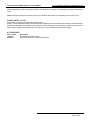
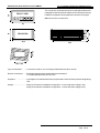
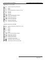
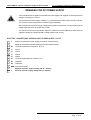
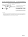
SERIES HM 207
Available Versions and Options
Ordering Codes
Hardware Customizations
General Technical Characteristics
Electrical Characteristics
Mechanical Characteristics
Electric Connections
Hardware Structure
Complement to the "User's Manual"
Technical Leaflet SM207700
Quality in Electronic Manufacturing
WARNINGS
-
This manual is a complement ot the "User's Manual"; it is necessary to get all information here indicated. We
recommend then a careful reading and, in case of misunderstandings, please contact QEM for any further
information by sending the assistance fax which you shall find enclosed to the manual of installation, maintenance
and assistance.
-
QEM is free from any responsibility for damages to people or things due to unobservance of the instructions and
prescriptions contained in this leaflet. We also state that the customer/purchaser must use the instrument
according to the instructions supplied by QEM. Any authorization for further use and replacement shall be deemed
as valid by QEM, in case of contestation, only if it has been written by QEM
-
No reprinting or republishing or delivery to third parties of this manual or of its parts is authorized unless a written
authorization is provided by QEM. Any infraction shall provoke a request of indemnization for damages on behalf
of QEM.
-
All rights generated by patents or models are reserved.
-
QEM reserves the right to partially or integrally modify the characteristics of the instrument described and the
enclosed documentation
-
This document is integrally valid except for mistakes or omissions.
Manual
Release
0
Modifications made to the Manual
New manual
Modifications
Date
15 / 05 / 97
Issuance and Approval
Issued by the Person in Charge for the Documentation: .............................................................................................
Approved by:
- Person in Charge of Technical Office: ................................................................................................
- Person in Charge of Commercial Office: ..........................................................................................
- Person in Charge for the Product: .............................................................................................
Pag. 1 di 15
Available Versions and Options in series HM 207
Quality in Electronic Manufacturing
The ordering codedefines the possible hardware configurations of the instrument according to the software version.
The ordering code is made of various fields. For each field it is possible to define only one among the available options
(CX = field X).
C1 C2 C3 / C4 / C5 / C6 / TXXX / VNXXX / VAC
AVAILABLE VERSIONS
FIELD 1 = Basic Hardware
FIELD 2
. = Basic version (power supply AC - see terminal board "Logic" on page 8)
N = Inputs of count for sensors NAMUR
V = DC Power supply
W = Digital inputs are not mounted
FIELD 3 = Software Version
AVAILABLE OPTIONS
FIELD 4
P
= Front panel without keyboard
PC = Front panel without keyboard with clear pushbutton
PE = Front panel without keyboard with enter pushbutton
T
= Keyboard of fixed programming
FIELD 5
0 = No analog output
1 = One analog output0÷10 V resolution 9 bits
2 = Two analog outputs 0÷10 V resolution 8 bits
3 = One analog output ± 10 V resolution 8 bits
4 = Two analog outputs ± 10 V resolution 7 bits
1A = One analog output 0÷10 V resolution 9 bits
2A = Two analog outputs 0÷10 V resolution 8 bits
3A = One analog output ± 10 V resolution 8 bits
4A = Two analog outputs ± 10 V resolution 7 bits
1B = One analog output 0÷10 V resolution 9 bits
2B = One analog output ± 10 V resolution 8 bits
L4 = 4 static outputs 24 V ac/dc - 50 mA
L6 = 6 static outputs 24 V ac/dc - 50 mA
U4 = 4 static outputs 110 V ac/dc - 0.2 A (it is possible to activate at the same time 3 outputs on 4)
U6 = 6 static outputs 110 V ac/dc - 0.2 A (it is possible to activate at the same time 3 outputs on 6)
FIELD 6
E
= Expansion card with 2 digital inputs and 3 static outputs 24 Vac/dc - 70 mA
I5 = Expansion card with 5 digital inputs
E4 = 3 digital inputs and 2 static outputs (in case it is installed also an analog output, the output U4 has un updating
time of 20 ms).
DF2 = Serial interface RS 422
RS2 = Serial interface RS 232C
FIELD 7
RS = Serial interface RS 232C
DF3 = Serial interface RS 422
DF4 = Serial interface RS 422 conenctable in multidrop
MD4 = Serial interface RS 485
Pag. 2 di 15
Versions and available options in series HM 207
Quality in Electronic Manufacturing
Txxx = Identification code of the keyboard where "xxx" identifies the number corresponding to the silk screenprinting
in use.
VNxxx = Special constructive versions, where "xxx" identifies the number corresponding to the version in use.
POWER SUPPLY (V AC)
It is possible to choose one among the following values:
24 Vac, 110 Vac and 220 Vac. We recommend to power supply the instrument at 24 Vac according to rules about safety
and the Standard about Low Voltage. To the purposes of th eordering code it is compulsory to define the instrument's
power supply voltage in alternated (unless you require the version with direct current power supply).
ACCESSORIES
Part number
46200037
23040001
Description
Extractable keyboard series 2
Front protection cover in polycarbonate IP54
Pag. 3 di 15
General technical characteristics of series HM 207
Quality in Electronic Manufacturing
Operation environment
Temperature:................................................... 0÷40 °C
Humidity:......................................................... 90% without condensate
Max. altitude:................................................... 2000 m on sea level
Atmosphere:.................................................... No corrosive gas
Temperature of transport and storage:................-25÷70 °C
Degree of protection of the container..................IP41 (Conform to EN 60529)
Degree of frontal protection .............................. IP51 (Conform to EN 60529)
Resistance to vibrations:.................................. Conform to IEC 68-2-6 (Theoretical data)
Resistance to shocks:......................................Conform to IEC 68-2-27 (Theoretical data)
Immunity to interferences:.................................Conform to EN 50082-2
Emission levels:...............................................Conform to EN 50081-2
The technical characteristics specified are valid if you observed all instructions of the "Manual of installation,
maintenance and assistance".
Pag. 4 di 15
Electrical characteristics of series HM 207
Quality in Electronic Manufacturing
HM 207 (Power supply AC)
Instrument's power supply:................................................................. Choice among 24-110-220 Vac ± 10%
50/60 Hz
Absorption in maximum hardware configuration:................................... 12 VA
Display:............................................................................................6 display h=14 mm + 1 display h=8 mm
high luminosity red colour
Memory:...........................................................................................Non volatile by semiconductor
Microprocessor:................................................................................ H8-520 16 bit - 20 MHz
Power supply issued by the instrument:.............................................. 12 Vdc - 100 mA +/- 4%
Attention: the dati related to the current supplied by the instrument are to be considered as maximum values.
You must perform then a careful check of the absorption and forecast if necessary some auxiliary feeders external to the instrument.
Digital inputs (logic, options E, I5, E4)
Optoinsulation:..................................................................................2500 V rms
Type of polarization:.......................................................................... NPN - PNP
Voltage of rated operation:................................................................. 12 Vdc
Voltage of logical status 0:................................................................. 0÷3V
Voltage of logical status 1:................................................................. 8÷24 V
Input resistance:............................................................................... 1.2 KW
Internal voltage drop:..........................................................................1.2 V
Minimum time of adquisition:.............................................................. Apx 50 ms (with a verification every 5 ms)
Minimum time of adquisition (interrupt - I1 - I2):.................................... 500 ms
Digital inputs (NAMUR)
Optoinsulation:........................................................................
Type of polarization:...................................................................
Tensione di funzionamento nominale:................................................
Resistance of logic status 0:.........................................................
Resistance of logic status 1:........................................................
Input resistance:.....................................................................
Internal voltage drop:.................................................................
Minimum time of adquisition:..........................................................
Minimum time of adquisition (interrupt - I1 - I2):..............................
2500 V rms
NPN / PNP
12 Vdc
50÷1 KW
2 KW ÷ ¥
220 W
6.5 V
Apx 50 ms (with a verification every 5 ms)
500 ms
Digital outputs (options E, E4)
Optoinsulation:..................................................................................2500 V rms
Load to be toggled:........................................................................... AC - DC (NPN - PNP)
Maximum operation voltage:............................................................... 24 Vac/dc
Internal voltage drop:..........................................................................2.5 V
Maximum current:............................................................................. 70 mA
Dispersion current:............................................................................ 20 mA
Toggling time from ON to OFF:........................................................... max 120 ms
Toggling time from OFF to ON:........................................................... max 8 ms
N.B. the toggling time depend upon the type of load; the data indicated refer to resistive loads.
Digital outputs (logic - options L4, L6)
Cards with 4 or 6 digital outputs. Characteristics as the standard digital outputs but with the following difference:
Maximum current:............................................................................. 50 mA
Power Digital outputs (options U4, U6)
Cards with 4 or 6 digital outputs. Characteristics as the standard digital outputs but with the following differences:
Maximum operation voltage:............................................................... 110 Vac/dc
Maximum current:............................................................................. 200 mA
Dispersion current:............................................................................ 1 mA
Pag. 5 di 15
Electrical characteristics series HM 207
Quality in Electronic Manufacturing
Analog outputs CNC
Voltage Range:................................................................................. according to the ordering code
Minimum Range (volt):-9.6 ÷ 9.80
Resolution:....................................................................................... according to the ordering code
Insulation:.........................................................................................2500 V
Max current:..................................................................................... 1 mA
Delta V f.s. : Delta I:.......................................................................... 95 mV/mA
Serial RS 232C - RS 422 - RS 485
Conform to electric standard efined by the type of serial. Maximum transmission speed is 9600 baud.
For RS 232C, the maximum length of wiring is 15 m; for RS 422 and RS 485 it is 1200 m
HM 207V (DC Power Supply) - See also paragraph "REMARKS FOR DC POWER SUPPLY"
Instrument's power supply:................................................................. 9÷26 Vdc
Absorption:....................................................................................... 335 mA (with power supply of 15 Vdc with 100
mA of load on the supply of transducers terminals 1 and 2).
power supplied issued by theinstrument:............................................. 12 Vdc 100 mA
Attention:
the datarelated to the current supplied by the instrument are to be considered as maximum values.
Perform then a careful check of the absorptions and forecast if necessary some auxiliary feeders external to the instrument.
Inputs (DC Power supply)
Not optoinsulated
Ingressi digitali (NAMUR - DC Power supply)
Not available
Uscite statiche (DC Power supply)
Not optoinsulated
Uscite statiche di potenza (DC Power supply)
Not optoinsulated
N.B. The technical and electrical characteristics mentioned above must be considered as valid only for the version with power supply in direct
current. The characteristics which are not mentiond are the same than those indicated for the version with power supply in alternated
current.
Pag. 6 di 15
48
Mechanical Characteristics of series HM 207
Quality in Electronic Manufacturing
The overall size, the drilling hole and everything described in this
paragraph must be deemed as valid for those instruments having
hardware configurations being different from those int he figure
VISTA
ANTERIORE
FRONT
VIEW
N.B. All sizes are in millimeters.
REAR VIEW
45
45
96
92,8
45 + 0,6
144
92,8 + 0,2
Type of instrument: ........ In a closed container, size according to DIN 43700 48 x 96 x 144 mm
Electric connections: ......Extractable polarized terminalboard with screw fixations.
Æ of stiff and flexible wires: 0.2÷2.5 mm
Keyboard: ......................In plexiglass covered with antiscratch polyester with 4 mechanical keys and 4 red signalling
leds.
Weight:.......................... 550 gr (in the maximum hardware configuration - version with power supply in AC)
330 gr (in the maximum hardware configuration - version with power supply in DC)
Pag. 7 di 15
Terminal boards series HM 207
Quality in Electronic Manufacturing
Logic
1
+
Positive of transducers power supply
2
-
Negative of transducers power supply
3
P1
Terminal of polarization of inputs I1, I2, I3, I4
4
I1
Input I1
5
I2
Input I2
6
I3
Input I3
7
I4
Input I4
8
C1
Terminal of polarization of outputs U1, U2
9
U1
Output U1
10
U2
Output U2
11
GND Ground connection
12
XXX Power supply voltage
13
XXX Power supply voltage
Card of inputs outputs / E4 / 1B / 2B / DF4 / MD4
14
P2
Terminal of polarization of inputs I5, I6, I7
15
I5
Input I5
16
I6
Input I6
17
I7
Input I7
18
C2
Terminal of polarization of outputs U3, U4
19
U3
Output U3
20
U4
Output U4
21
GND Common of analog output (cold pole)
22
AN1 Analog output (hot pole)
23
RX
Reception of serial port DF4 / Channel A serial port MD4
24
TX
Transmission serial port DF4 / Channel B serial port MD4
25
RX
Not allowed reception serial port DF4
26
TX
Not allowed transmission serial port DF4
Pag. 8 di 15
Terminal boards of series HM 207
Quality in Electronic Manufacturing
Options E / 0 / 1 / 2 / 3 / 4 / RS
14
P2
Terminal of polarization of inputs I5, I6
15
I5
Input I5
16
I6
Input I6
17
C2
Terminal of polarization of outputs U3, U4, U5
18
U3
Output U3
19
U4
Output U4
20
U5
Output U5
21
GND Common of analog output (cold pole)
22
AN1 Analog output 1 (hot pole)
23
AN2 Analog output 2 (hot pole)
24
GND Common of serial port RS
25
RX
Reception serial port RS
26
TX
Transmission serial port RS
Opzions I5 / 1A / 2A / 3A / 4A / DF3
14
P2
Terminal of polarization of inputs I5, I6, I7, I8, I9
15
I5
Input I5
16
I6
Input I6
17
I7
Input I7
18
I8
Input I8
19
I9
Input I9
20
GND Common of analog output (cold pole)
21
AN1 Analog output 1 (hot pole)
22
AN2 Analog output 2 (hot pole)
23
RX
Reception serial port DF3
24
TX
Transmission serial port DF3
25
RX
Not allowed reception serial port DF3
26
TX
Not allowed transmission serial port DF3
Pag. 9 di 15
Terminal boards of series HM 207
Quality in Electronic Manufacturing
Options L4 / L6 / U4 / U6 / 3 / RS2 / DF2
14
C2
Comon of outputs U3÷U8
15
U3
Output U3
16
U4
Output U4
17
U5
Output U5
18
U6
Output U6
19
U7
Output U7
20
U8
Output U8
21
GND Common of serial port RS2
22
RX
Reception serial ports RS2 / DF2
23
TX
Transmission serial ports RS2 / DF2
24
RX
Not allowed reception serial port DF2
25
TX
Not allowed transmission serial port DF2
Pag. 10 di 15
Series HM 207: version with power supply in direct current
Quality in Electronic Manufacturing
REMARKS FOR DC POWER SUPPLY
-
The terminals 2 and 12, negative of transducers' power supply and negative of instrument's power
supply are internally in common.
-
The polarities of the power supply voltage (+ / -), must observe the marks of the terminals 12 and 13.
The inversion of this wiring does not create any type of damage.
-
We recommend to use power supply voltage of the transducers (terminals 1 and 2) only if the power
supply of the instrument is greater than 15 Vdc.
-
The instrument can mount all available expansion cards for the series HM 207 (in these cases we
suggest to supply the instrument with a voltage greater than 15 Vdc).
ELECTRIC CONNECTIONS VERSION WITH POWER SUPPLY IN DC
1
+
Positive of transducers'power supply (see electric characteristics)
2
-
Negative of transducers'power supply (see electric characteristics)
3
P1
Terminal of polarization of inputs I1, I2, I3, I4
4
I1
Input I1
5
I2
Input I2
6
I3
Input I3
7
I4
Input I4
8
C1
Terminal of polarization of outputs U1, U2
9
U1
Output U1
10
U2
Output U2
11
GND Ground connection
12
-
Negative of power supply voltage Vdc (9 ÷ 26 Vdc).
13
+
Positive of power supply voltage Vdc (9 ÷ 26 Vdc).
Pag. 11 di 15
Series HM 207: version with power supply in direct current
Quality in Electronic Manufacturing
REMARKS FOR DC POWER SUPPLY
GROUND CONNECTION AND CABLE SCREENING
INSTRUMENT'S TERMINAL BOARD
Connect the reference of the power supply (0V) to
the metallic mass and to the ground.
The braidings of the screened cables must be
ground connected respecting all instructions
indicated in the paragraph "Use of the screened
cable" of the Manual of Installation, maintenance
and assistance".
Even though the reference of the power supplt (0 V)
is ground connected, you must absolutely not use
the ground for the return of current.
WARNINGS
- Before extracting or introducing the connectors or to handle in any way the instrument, remove power supply to the
instrument and to all parts conencted to it; wait at least two minutes from the moment of the switching OFF in order
to allow all the internal energy to be discharged.
- It is COMPULSORY to perform the connections as indicated in the drawing.
Pag. 12 di 15
Quality in Electronic Manufacturing
REMARKS
Pag. 13 di 15
Quality in Electronic Manufacturing
REMARKS
Pag. 14 di 15
Quality in Electronic Manufacturing
REMARKS
Pag. 15 di 15