1
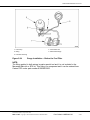
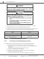
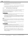
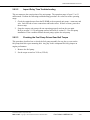
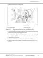
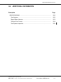
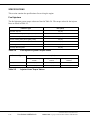
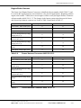
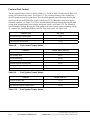
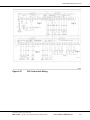
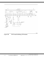
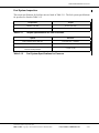
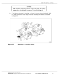
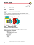
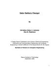
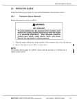
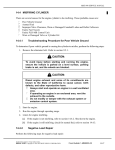
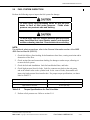
MBE 4000 SERVICE MANUAL
2.9
FUEL SYSTEM INSPECTION
Perform the following steps to inspect the fuel system for damage:
To avoid injury from penetrating fluids, do not put your
hands in front of fluid under pressure. Fluids under
pressure can penetrate skin and clothing.
To avoid injury from fire, keep all potential ignition sources
away from diesel fuel, open flames, sparks, and electrical
resistance heating elements. Do not smoke when refueling.
NOTE:
For additional safety precautions, refer to the General Information section of the MBE
4000 Service Manual (6SE412).
1. Check fuel delivery lines looking for deformation or bent lines, creating restriction and/or
obstruction of the flow.
2. Check suction lines and connections looking for damage or under torque, allowing air
to enter the fuel system.
3. Check the fuel tank installation. Look for bent/blocked lines, and leaks.
4. Check high-pressure lines for leaks. Look for connector nut leaks at the unit pump
and at the transfer tube on the cylinder head. In the event of leaks, disassemble and
inspect the high-pressure lines/transfer tube. For proper torque specifications, see those
listed in Table 2-2.
Table 2-2
Component
Torque
Transfer Tube Nut
45 N·m (33 lb·ft)
High Pressure Line Nuts
30 N·m (22 lb·ft)
Torque Specifications for Fuel Line Nuts
5. Perform a fuel pressure test. Refer to section 2.9.1.
All information subject to change without notice.
6SE412 0206 Copyright © 2003 DETROIT DIESEL CORPORATION
From Bulletin 6-MBE4000-03
2-41
2.9
FUEL SYSTEM INSPECTION
2.9.1
Performing a Fuel Pressure Test
Perform the following steps to conduct a fuel pressure test:
1. Install the pressure gauge on the fuel system. There are two possible setups for this
installation. Setup 1 has the gauge installed after the fuel filter. See Figure 2-23. Setup 2
has the gauge installed before the fuel filter. See Figure 2-24.
1. Fitting
4. Fuel Outlet Line
2. Fuel Filter Housing
5. Unit Pump
3. Mechanical Gauge
Figure 2-23
2-42
Gauge Installation – After the Fuel Filter
From Bulletin 6-MBE4000-03
All information subject to change without notice.
6SE412 0206 Copyright © 2003 DETROIT DIESEL CORPORATION
MBE 4000 SERVICE MANUAL
1. Fuel Pump
4. Fuel Outlet Line
2. Fitting
5. Mechanical Gauge
3. Fuel Filter Housing
Figure 2-24
Gauge Installation – Before the Fuel Filter
NOTE:
The fitting applied in both setups is not a special tool and it is not included in the
Mercedes-Benz kit or SPX kit. This fitting is a component and it can be ordered from
Canton PDC under part number 915039012205.
All information subject to change without notice.
6SE412 0206 Copyright © 2003 DETROIT DIESEL CORPORATION
From Bulletin 6-MBE4000-03
2-43
2.9
FUEL SYSTEM INSPECTION
To avoid injury before starting and running the engine,
ensure the vehicle is parked on a level surface, parking
brake is set, and the wheels are blocked.
Diesel engine exhaust and some of its constituents are
known to the State of California to cause cancer, birth
defects, and other reproductive harm.
Always start and operate an engine in a well ventilated
area.
If operating an engine in an enclosed area, vent the
exhaust to the outside.
Do not modify or tamper with the exhaust system or
emission control system.
2. Start the engine and warm it up to working temperatures: 80 - 95 C (176 - 203 F).
3. Check the fuel pressure at two points: idle speed and rated speed.
4. Compare the test results with the fuel systems specifications for pressure listed in Table 2-3.
If any of the readings are out of spec, follow the proper troubleshooting steps.
Speed
Pressure
Fuel Pressure Test at idle rpm
2 bar (29 psi) –minimum
Fuel Pressure Test at rated rpm
5.5 – 6.5 bar (80 – 95 psi)
Maximum difference between fuel filter housing
inlet and outlet pressure
0.3 bar (4 psi)
Table 2-3
2.9.1.1
Fuel System Specifications for Pressure
Fuel Pressure Test Troubleshooting Procedures
For results out of specs on the fuel pressure test, check the following appropriate steps:
1. At idle rpm, with fuel pressure lower than 2 bar (29 psi), check the following:
Check the pressure valve at the end of the fuel gallery. Look for opening pressure 2
bar (29 psi).
Check the fuel pump assembly (bearing and/or driven gear).
Check to see if the fuel system is drawing air.
2. At rated rpm, for fuel pressure lower than 5.5 bar (80 psi), check the following:
Check the water separator filter condition.
Check for restriction at the check valve on the PLD-MR heat exchange plate.
2-44
From Bulletin 6-MBE4000-03
All information subject to change without notice.
6SE412 0206 Copyright © 2003 DETROIT DIESEL CORPORATION
MBE 4000 SERVICE MANUAL
Check the main fuel filter condition, looking for saturation or any damaged seal
allowing flow of fuel from the pressure side to the return side.
Check for leaks at the suction lines from the tank.
Check the fuel pump assembly (bearing and/or driven gear).
Look for leaks and/or a damaged fuel pump.
Check for restriction at the check valve on the fuel filter return line to tank.
3. At rated rpm, for fuel pressure higher than 6.5 bar (95 psi), check the following:
Check the return line and injector spill line, looking for restrictions or bent lines.
Check the fuel pressure valve for a blocked or restricted regulator orifice.
2.9.2
Performing a Fuel System Test using minidiag2
To perform a fuel system test using minidiag2, perform the following steps:
To avoid injury when working near or on an operating
engine, remove loose items of clothing, jewelry, tie back or
contain long hair that could be caught in any moving part
causing injury.
Diesel engine exhaust and some of its constituents are
known to the State of California to cause cancer, birth
defects, and other reproductive harm.
Always start and operate an engine in a well ventilated
area.
If operating an engine in an enclosed area, vent the
exhaust to the outside.
Do not modify or tamper with the exhaust system or
emission control system.
NOTE:
Before running the test, warm the engine to normal operating temperatures: 80 -95 C
(176 -203 F).
1. Plug your minidiag2 into the truck diagnostic connector and follow the instructions in the
minidiag2 Supplement Manual to connect to the VCU/PLD-MR system.
2. After establishing the connection with the truck, choose option 4 – Routines.
3. Under Routines section, select option 4 – Idle Smoothly Balance.
All information subject to change without notice.
6SE412 0206 Copyright © 2003 DETROIT DIESEL CORPORATION
From Bulletin 6-MBE4000-03
2-45
2.9
FUEL SYSTEM INSPECTION
4. Check each cylinder value for this routine and compare your results with
the troubleshooting and proceed as described for any results out of spec.
Refer to section 2.9.2.1.
5. Still connected to truck, look for option 5 – Impact Time Delay, under the Routines section.
6. Select it and check each cylinder value for this routine and compare your results with the
troubleshooting and proceed as described for results out of spec.
2.9.2.1
Idle Smoothly Balance Troubleshooting
This test measures the percentage of fuel delivery for each cylinder in order to maintain a smooth
operation at idle. Operational range for this test: from -3% (negative) to 3% (positive).
Identify the cylinder with the biggest absolute value – highest positive or lowest negative. The
troubleshooting steps for both conditions are:
For Highest Positive:
1. Check torque at all the transfer tubes nuts (45 N·m [33 lb·ft]). Run the test again. If the
results are out of operational range, proceed to next step.
2. Find the cylinder with the result closest to zero. Swap the injector nozzle holder and the
transfer tube between this cylinder and the cylinder with the highest result. Run the test
again. If the highest result follows the injector nozzle holder, replace the nozzle holder.
If not, proceed to the next step.
NOTE:
After removing the injector nozzle holders and transfer tubes, check the coupling area
between both components and the seal rings. If any defect or damage is found, replace
the damaged parts.
3. Return both injector nozzle holders and transfer tubes to their original positions and run
the impact delay time and compression test routines.
For Lowest Negative:
1. Check torque at all the transfer tubes nuts (45 N·m [33 lb·ft]). Run the test again. If the
results are out of the operational range, proceed to the next step.
2. Find the cylinder with the lowest result, remove the injector nozzle holder and check the
opening pressure. If the pressure is lower than the minimum spec (275 bar [3989 psi]),
replace the injector nozzle holder. If the pressure is within the spec, proceed to the next
step.
3. Run a compression test using minidiag2, ProLink reader, or DDDL 5.0 (refer to the
Diagnostic Tool Manual for instructions to run this test). The readings must be 75% or
higher. For readings lower than 75%, remove the oil pan and cylinder head and check
for damaged components.
2-46
From Bulletin 6-MBE4000-03
All information subject to change without notice.
6SE412 0206 Copyright © 2003 DETROIT DIESEL CORPORATION
MBE 4000 SERVICE MANUAL
2.9.2.2
Impact Delay Time Troubleshooting
This test measures the reaction time of the unit pumps. The operation range is from 1.2 to 2.1
milliseconds. Perform the following troubleshooting procedure for values out of the operating
range:
1. Check the engine harness from the PLD-MR to the suspected unit pump – connectors and
wire. Look for bad or loose connections and broken wires. If there are none, proceed to
the next step.
2. Swap the suspect unit pump with one operating properly and run the test again.
Refer to section 2.1.1 for unit pump removal and refer to section 2.1.2 for unit pump
installation. If the condition follows the unit pump, replace the unit pump.
2.9.2.3
Checking the Fuel Pump Driven Gear Bolt Torque
This procedure describes how to check the fuel pump assembly for any play or wear on the
fuel pump shaft drive gear mounting bolt. Any play in this component has a big impact on
engine performance.
1. Remove the fuel pump.
2. Set the torque wrench to 30 N·m (22 lb·ft).
All information subject to change without notice.
6SE412 0206 Copyright © 2003 DETROIT DIESEL CORPORATION
From Bulletin 6-MBE4000-03
2-47
2.9
FUEL SYSTEM INSPECTION
NOTICE:
Do not apply a torque over 30 N·m (22 lb·ft). Excessive torque
can cause the bolt/gear failure.
3. Turn the torque wrench as shown by the arrow in until the torque wrench “clicks.” This
resistance ensures that the fuel pump drive gear is in good condition. In the event of NO
resistance found with shaft turning freely, proceed to the next step. See Figure 2-25.
1. Torque wrench
3. Fuel Pump
2. Fuel Pump Drive Gear Splines
Figure 2-25
Checking Fuel Pump Drive Gear
4. Remove the fuel pump drive gear cover.
2-48
From Bulletin 6-MBE4000-03
All information subject to change without notice.
6SE412 0206 Copyright © 2003 DETROIT DIESEL CORPORATION
MBE 4000 SERVICE MANUAL
5. Remove the bolt and gear. See Figure 2-26.
1. Cover
3. Fuel Pump Shaft
2. Drive Gear Mounting Bolt
4. Fuel Pump Drive Gear
Figure 2-26
Removing/Installing Fuel Pump Drive Gear and Bolt
6. Check the mounting between bolt, gear, and shaft. Look for damaged parts. Replace any
damaged part in order to avoid it coming loose again.
7. Install gear and bolt. Apply Loctite® 271 sealant to the bolt. For the correct tightening
of the bolt, install the special tool J 36187 to the fuel pump spline and block the shaft
movement. See Figure 2-25.
8. Torque bolt to 30 N·m (22 lb·ft).
9. Apply Loctite 574 sealant and install the cover. Torque 50 N·m (37 lb·ft).
10. Install new gasket and the fuel pump. Torque to the fuel pump bolts will be 25 N·m
(18 lb·ft).
All information subject to change without notice.
6SE412 0206 Copyright © 2003 DETROIT DIESEL CORPORATION
From Bulletin 6-MBE4000-03
2-49
2.9
2-50
FUEL SYSTEM INSPECTION
From Bulletin 6-MBE4000-03
All information subject to change without notice.
6SE412 0206 Copyright © 2003 DETROIT DIESEL CORPORATION
MBE 4000 SERVICE MANUAL
2.A
ADDITIONAL INFORMATION
Description
Page
SPECIFICATIONS .............................................................................................
2-52
Fuel Injectors ..................................................................................................
2-52
Engine Brake Harness ...................................................................................
2-53
Fuel and Fuel Control .....................................................................................
2-54
Fuel System Inspection ..................................................................................
2-59
All information subject to change without notice.
6SE412 0206 Copyright © 2003 DETROIT DIESEL CORPORATION
From Bulletin 6-MBE4000-03
2-51
SPECIFICATIONS
This section contains the specifications for servicing the engine.
Fuel Injectors
The fuel injection system torque values are listed in Table 2-4. The torque values for the injector
lines are listed in Table 2-5.
Fastener Type
N·m (lb·ft)
Fuel Filter Cap Nut
25 (18)
Fuel Return Line Fittings (at fuel gallery inlet)
50 (37)
Hollow-Core Banjo Bolts
50 (37)
Pressure Limiting Valve (at fuel gallery outlet)
50 (37)
Protective Sleeve
45 (33)
Tensioning Arm Retaining Bolt
50 (37)
Unit Pump Mounting Bolts
65 (48)
Table 2-4
Fuel Injection System Torque Values
Fastener Type
N·m (lb·ft)
Using a 12-in. torque
wrench
Using a 24-in. torque
wrench
Required Torque on
Fastener
Injector Line Nuts
27 (20)
25 (18)
30 (22)
Transfer Tube Thrust Bolt
40 (30)
36 (27)
45 (33)
Table 2-5
2-52
Injector Lines Torque Values
From Bulletin 6-MBE4000-03
All information subject to change without notice.
6SE412 0206 Copyright © 2003 DETROIT DIESEL CORPORATION
MBE 4000 SERVICE MANUAL
Engine Brake Harness
The former 8-pin Engine Harness Connector is identified with part number A460 150 00 33, and
it is used in the engines that have one solenoid air valve for the engine brakes. Beginning with the
engine serial number 739080, these current engines will have an 8-pin Engine Harness Connector
with part number A460 150 01 33. The changes in the harness connections between the former
and current 8-pin harness connector are Listed in Table 2-6and listed in Table 2-7.
Description
8-Pin Engine Harness Connector
PLD-MR 55-Pin Connector
Fan Control 1, switch to Bat- (PV3)
A
41
Fan Control 2, switch to Bat- (PV4)
B
43
Output Ground (PV)
C
11
Fan and Wastegate/E-Flap Voltage
Supply (PV1, 3, 4)
D
12
Exhaust Flap/Wastegate Control,
switch to Bat- (PV1)
E
51
Fan and Wastegate/E-Flap Voltage
Supply (PV1, 3, 4)
F
12
Turbo Brake Control, switch to Bat(PV6)
G
40
Turbo Brake Voltage Supply (PV6)
H
42
Table 2-6
Former Harness Connector A460 150 00 33
Description
8-Pin Engine Harness Connector
PLD-MR 55-Pin Connector
Fan Control #1, switch to Bat- (PV3)
A
41
Fan Control #2, switch to Bat- (PV4)
B
43
Compression Brake Control, switch
to Bat- (PV2)
C
50
Fan and Wastegate/E-Flap Voltage
Supply (PV1, 3, 4)
D
12
Exhaust Flap/Wastegate Control,
switch to Bat- (PV1)
E
51
Compression Brake Voltage Supply
(PV2)
F
52
Turbo Brake Control, switch to Bat(PV6)
G
40
Turbo Brake Voltage Supply (PV6)
H
42
Table 2-7
Current Harness Connector A460 150 01 33
All information subject to change without notice.
6SE412 0206 Copyright © 2003 DETROIT DIESEL CORPORATION
From Bulletin 6-MBE4000-03
2-53
Fuel and Fuel Control
The fuel control torque values are listed in Table 2-8. Listed in Table 2-9 and listed in Table 2-10
are the fuel system torque values. See Figure 2-27 for a harness drawing of the wiring from
the PLD (pump and nozzle) control unit. For a detailed (partial) harness drawing showing the
interface between the PLD and the vehicle control unit (VCU) through the electronic engine
frontwall connector, see Figure 2-28. For a detailed (partial) harness drawing showing the PLD
wiring to the proportioning valves and the oil system sensors, see Figure 2-29. For a detailed
(partial) harness drawing showing the PLD wiring to the other system sensors, including charge
air, coolant, fuel, crank angle position, and TDC (top dead center), see Figure 2-30.
Fastener Type
N·m (lb·ft)
Fuel Heat Exchanger Mounting Bolts
8 (6)
Fuel Lines
50 (37)
PLD Control Unit Mounting Bolts
15 (11)
Table 2-8
Fuel Control Torque Values
Fastener
Torque Value, mm (in.)
Fuel Filter Cap
25 (18)
Fuel Line Banjo Bolts
50 (37)
Fuel Line Pipe Fittings
50 (37)
High-Pressure Fuel Lines
30 (22)
Fuel/Water Separator Mounting Nuts
50 (37)
Fuel Filter Housing Mounting Bolts
25 (18)
Fuel Pump Mounting Bolts
25 (18)
Table 2-9
Fuel System Torque Values
Fastener
Torque, mm (in.)
Fuel Spill Line Banjo Bolt
15 (11)
Fuel Pump Driven Gear Bolt
30 (22)
Fuel Temperature Sensor to Engine Block
30 (22)
Table 2-10
2-54
Fuel System Torque Values
From Bulletin 6-MBE4000-03
All information subject to change without notice.
6SE412 0206 Copyright © 2003 DETROIT DIESEL CORPORATION
MBE 4000 SERVICE MANUAL
Figure 2-27
PLD Control Unit Wiring
All information subject to change without notice.
6SE412 0206 Copyright © 2003 DETROIT DIESEL CORPORATION
From Bulletin 6-MBE4000-03
2-55
Figure 2-28
2-56
PLD Control Unit Wiring, VCU Interface
From Bulletin 6-MBE4000-03
All information subject to change without notice.
6SE412 0206 Copyright © 2003 DETROIT DIESEL CORPORATION
MBE 4000 SERVICE MANUAL
Figure 2-29
PLD Control Unit Wiring, Proportioning Valves and Oil System
Sensors
All information subject to change without notice.
6SE412 0206 Copyright © 2003 DETROIT DIESEL CORPORATION
From Bulletin 6-MBE4000-03
2-57
Figure 2-30
2-58
PLD Control Unit Wiring, Miscellaneous Sensors
From Bulletin 6-MBE4000-03
All information subject to change without notice.
6SE412 0206 Copyright © 2003 DETROIT DIESEL CORPORATION
MBE 4000 SERVICE MANUAL
Fuel System Inspection
The torque specifications for fuel line nuts are listed in Table 2-11. The fuel system specifications
for pressure are listed in Table 2-12.
Table 2-11
Component
Torque
Transfer Tube Nut
45 N·m (33 lb·ft)
High Pressure Line Nuts
30 N·m (22 lb·ft)
Torque Specifications for Fuel Line Nuts
Speed
Pressure
Fuel Pressure Test at idle rpm
2 bar (29 psi) – minimum
Fuel Pressure Test at rated rpm
5.5 – 6.5 bar (80 – 95 psi)
Maximum difference between fuel filter housing
inlet and outlet pressure
0.3 bar (4 psi)
Table 2-12
Fuel System Specifications for Pressure
All information subject to change without notice.
6SE412 0206 Copyright © 2003 DETROIT DIESEL CORPORATION
From Bulletin 6-MBE4000-03
2-59
2-60
From Bulletin 6-MBE4000-03
All information subject to change without notice.
6SE412 0206 Copyright © 2003 DETROIT DIESEL CORPORATION