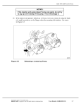
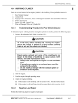
1
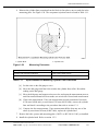
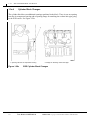
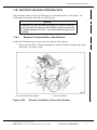
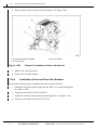
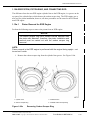
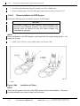
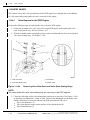
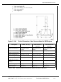
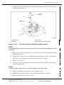
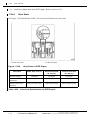
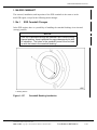
1
ENGINE
Section
Page
1.1
CYLINDER HEAD COVER ......................................................................
1-3
1.2
CYLINDER HEAD ....................................................................................
1-5
1.3
CYLINDER BLOCK ..................................................................................
1-24
1.3A EGR CYLINDER HEAD AND BLOCK .....................................................
1-40
1.3B EGR FRONT AND REAR LIFTER BRACKETS ....................................... 1-40c
1.4
ENGINE BRAKE ......................................................................................
1-40f
1.5
FRONT RADIAL SEAL .............................................................................
1-46
1.6
REAR RADIAL SEAL ...............................................................................
1-49
1.7
CRANKSHAFT ASSEMBLY .....................................................................
1-52
1.8
FRONT COVER HOUSING .....................................................................
1-77
1.9
CRANKSHAFT VIBRATION DAMPER .....................................................
1-79
1.10
FLYWHEEL ..............................................................................................
1-81
1.11
RING GEAR .............................................................................................
1-90
1.12
PILOT BEARING ......................................................................................
1-94
1.13
ENGINE CRANKING TOOL .....................................................................
1-96
1.14
FLYWHEEL HOUSING .............................................................................
1-98
1.15
PISTON, PISTON RING, AND CONNECTING ROD ............................... 1-100
1.15A EGR PISTON, PISTON RING, AND CONNECTING ROD ...................... 1-166
1.16
VALVES .................................................................................................... 1-129
1.16A EGR VALVES ........................................................................................... 1-152
1.17
ROCKER ARM ......................................................................................... 1-157f
1.18
CAMSHAFT AND CAMSHAFT SENSOR ................................................ 1-157j
1.18A EGR CAMSHAFT ..................................................................................... 1-169
1.A
ADDITIONAL INFORMATION .................................................................. 1-171
All information subject to change without notice.
1-2
From Bulletin 2-MBE4000-04
6SE412 0206 Copyright © 2004 DETROIT DIESEL CORPORATION
MBE 4000 SERVICE MANUAL
6. Measure the cylinder liner protrusion from the block in four places, once at each slot in the
measuring plate. See Figure 1-28. The acceptance/rejection criteria is listed in Table 1-11.
1. Cylinder Block
Figure 1-28
2. Cylinder Liner
Measuring Protrusion
Description
Value: mm (in.)
Cylinder Liner Protrusion From Block
0.230–0.330 (0.0090–0.0130)
Difference Between the Four Measuring Points
Max.: 0.02 (0.0007)
Table 1-11
Specifications for Measuring Cylinder Liner Protrusion
[a]
Set the scale on the dial gauge to zero.
[b]
Move the dial gauge until the feeler touches the cylinder liner collar. Record the
reading on the dial gauge.
[c]
Move the dial gauge and support to the next slot, and repeat the measurement process,
until four measurements have been made, one at each slot. Record each measurement.
[d]
Check each measurement. If any one measurement records protrusion of less than
0.230 mm (0.0090 inch), or more than 0.330 mm (0.0130 inch), remove the cylinder
liner and check it according to the procedures that refer to section 1.3.1.
[e]
Compare the four measurements. If any measurement differs from any one of the
others by more than 0.02 mm (0.0007 inch), replace the cylinder liner.
7. Remove the bolts, spacers and measuring plate (J 46071 or 402 589 00 21 00), as installed.
8. Install the cylinder head. Refer to section 1.2.2.
All information subject to change without notice.
6SE412 0206 Copyright © 2004 DETROIT DIESEL CORPORATION
From Bulletin 2-MBE4000-04
1-39
1.3A
EGR CYLINDER HEAD AND BLOCK
1.3A EGR CYLINDER HEAD AND BLOCK
There are several minor changes in the cylinder liner, block and engine lifter brackets between the
MBE 4000 EGR engine and the non-EGR engine.
1.3a.1
EGR Cylinder Head Installation
Be aware of the following notice when installing the cylinder head on an EGR engine:
NOTICE:
Be sure the carbon scraper ring is seated in the groove on the
top part of the cylinder liner before installing a new cylinder head
gasket and the cylinder head, otherwise component damage can
result. See Figure 1-28a.
1. Cylinder Liner
3. Installed Piston
2. Carbon Scraper Ring
Figure 1-28a
4. Carbon Scraper Ring located in groove in cylinder
liner
Installed Carbon Scraper Ring
NOTE:
All remaining installation procedures for the cylinder head are identical to a
non-EGR engine.
All information subject to change without notice.
1-40
From Bulletin 2-MBE4000-04
6SE412 0206 Copyright © 2004 DETROIT DIESEL CORPORATION
MBE 4000 SERVICE MANUAL
1.3a.2
Cylinder Head Changes
There is also drilling in the head to attach the new EGR cooler support bracket. There is hardening
at block division face of cylinder head also. See Figure 1-28b.
1. Drilling to attach the EGR Cooler Support Bracket
Figure 1-28b
1.3a.3
2. Hardening at Block Division Face
EGR Cylinder Head Changes
Cylinder Liner Changes
One difference between the non-EGR cylinder liner to the EGR model is a groove on the top part
of the cylinder liner, which houses the carbon scraper ring. See Figure 1-28a. The carbon scraper
ring for the EGR engine is in the area previously hardened in the non-EGR cylinder liner. Its
purpose is to inhibit coke formation.
All information subject to change without notice.
6SE412 0206 Copyright © 2004 DETROIT DIESEL CORPORATION
From Bulletin 2-MBE4000-04
1-a
1.3A
EGR CYLINDER HEAD AND BLOCK
1.3a.4
Cylinder Block Changes
The cylinder block has two additional openings machined in the block. There is now an opening
near the air compressor housing and an opening flange for attaching the coolant inlet pipe going
to the EGR cooler. See Figure 1-28c.
1. Opening near the air compressor housing
Figure 1-28c
2. Flange for attaching coolant inlet pipe
EGR Cylinder Block Changes
All information subject to change without notice.
1-b
From Bulletin 2-MBE4000-04
6SE412 0206 Copyright © 2004 DETROIT DIESEL CORPORATION
MBE 4000 SERVICE MANUAL
1.3B EGR FRONT AND REAR LIFTER BRACKETS
The front lifter bracket on the non-EGR engine was moulded into the coolant pump. The
EGR engine has separate front and rear lifter brackets.
NOTICE:
A spreader bar must be used at all times in conjunction with the
front and rear lifter brackets to lift the EGR engine to ensure that
no engine damage will result. The brackets are designed to lift
vertically.
1.3b.1
Removal of Front and Rear Lifter Brackets
Perform the following steps to remove the front and rear lifter brackets:
1. Remove the four M10 x 25 mm mounting bolts from the front lifter bracket and remove
the bracket. See Figure 1-28d.
1. Front Lifter Bracket Mounting Bolts
Figure 1-28d
2. Front Lifter Bracket
Removal / Installation of Front Lifter Bracket
All information subject to change without notice.
6SE412 0206 Copyright © 2004 DETROIT DIESEL CORPORATION
From Bulletin 2-MBE4000-04
1-c
1.3B
EGR FRONT AND REAR LIFTER BRACKETS
2. Remove the two bolts from the rear lifter bracket. See Figure 1-28e.
1. Rear Lifter Bracket Mounting Bolts
3. Rear Lifter Bracket
2. Vent Line Bracket
Figure 1-28e
Removal / Installation of Rear Lifter Bracket
3. Remove the vent line bracket.
4. Remove the rear lifter bracket.
1.3b.2
Installation of Front and Rear Lifter Brackets
Perform the following steps to install the front and rear lifter brackets:
1. Install the front lifter bracket using the four M10 x 25 mm mounting bolts.
See Figure 1-28d.
2. Torque the four bolts to 60 N·m (44 lb·ft).
3. Install the rear lifter bracket using two mounting bolts. See Figure 1-28e.
4. Torque the two bolts to 200 N·m (147.5 lb·ft).
All information subject to change without notice.
1-d
From Bulletin 2-MBE4000-04
6SE412 0206 Copyright © 2004 DETROIT DIESEL CORPORATION
MBE 4000 SERVICE MANUAL
This page intentionally left blank.
All information subject to change without notice.
6SE412 0206 Copyright © 2004 DETROIT DIESEL CORPORATION
From Bulletin 2-MBE4000-04
1-e
1.4
ENGINE BRAKE
1.4
ENGINE BRAKE
Engine braking is controlled by a pneumatically-operated exhaust brake on the turbocharger in
conjunction with constant-throttle valves on the cylinder head. The exhaust back-pressure is used
by the exhaust brake to increase braking performance. The constant-throttle valves use the air that
escapes through them on the compression stroke to provide braking force.
The constant throttles are small valves which are built into the cylinder heads and positioned
opposite the exhaust valves. When open, a link is created between the combustion chamber and
the exhaust port. When the engine brake is switched on, the constant-throttle valves are opened
by pneumatic pressure.
NOTE:
When in emergency running mode (constant rpm), the engine brake can be activated
only when the engine is in overrun. When constant rpm has been attained, the engine
brake is automatically turned off.
For greater braking power, an optional turbo brake is available.
1.4.1
Constant-Throttle Valve Removal
Remove the constant-throttle valve as follows:
1. Remove the cylinder head. Refer to section 1.2.1.
2. Remove the injector nozzle. Refer to section 2.3.1.
All information subject to change without notice.
1-f
From Bulletin 2-MBE4000-04
6SE412 0206 Copyright © 2004 DETROIT DIESEL CORPORATION
MBE 4000 SERVICE MANUAL
1.15A EGR PISTON, PISTON RING, AND CONNECTING ROD
The difference from the non-EGR engine cylinder liner to the EGR engine, is a groove on the
top part of the cylinder liner, which houses the carbon scraper ring. The EGR engine uses a
new tool for piston installation; however, all other procedures are the same for the EGR and
non-EGR engine.
1.15a.1
Piston Removal for EGR Engine
Perform the following steps to remove the piston from an EGR engine:
NOTICE:
The carbon scraper ring has a smaller internal diameter than
the piston skirt diameter; therefore, the piston installation and
removal must be carried out with the carbon scraper ring
removed.
NOTE:
Piston removal in the EGR engine is performed with the engine facing upright – not
turned on it's side.
1. Remove the carbon scraper ring from the cylinder liner groove. See Figure 1-98a.
1. Cylinder Liner
3. Installed Piston
2. Carbon Scraper Ring
4. Installed Carbon Scraper Ring
Figure 1-98a
Removing Carbon Scraper Ring
All information subject to change without notice.
6SE412 0206 Copyright © 2004 DETROIT DIESEL CORPORATION
From Bulletin 2-MBE4000-04
1-166
1.15A
EGR PISTON, PISTON RING, AND CONNECTING ROD
2. Push the piston and connecting rod assembly out of the cylinder liner.
3. Follow remaining steps for non-EGR engine piston removal. Refer to section 1.15.1.
1.15a.2
Piston Installation for EGR Engine
Perform the following steps to install the piston in an EGR engine:
NOTICE:
The carbon scraper ring has a smaller internal diameter than
the piston skirt diameter; therefore, the piston installation and
removal must be carried out with the carbon scraper ring
uninstalled or removed.
NOTE:
Piston installation in the EGR engine is performed with the engine facing upright – not
turned on it's side.
1. Install J tool (J 47110) to the cylinder block. See Figure 1-98b.
1. Piston
Figure 1-98b
Installation of Piston
NOTE:
There are NO arrows on the top of the EGR piston to direct the installation. The piston
can be installed in any direction and it will be correct.
All information subject to change without notice.
1-167
From Bulletin 2-MBE4000-04
6SE412 0206 Copyright © 2004 DETROIT DIESEL CORPORATION
MBE 4000 SERVICE MANUAL
2. Push the piston into cylinder liner, using ring compressor J tool (J 45983) to compress the
piston rings.
3. Clean the carbon scraper ring seat in the cylinder liner.
4. After piston is installed, install carbon scraper ring in the cylinder liner groove.
See Figure 1-98a.
5. Check carbon scraper ring for correct fit after installation.
6. Follow remaining steps for piston installation in a non-EGR engine. Refer to section 1.15.2.
All information subject to change without notice.
6SE412 0206 Copyright © 2004 DETROIT DIESEL CORPORATION
From Bulletin 2-MBE4000-04
1-168
1.15A
EGR PISTON, PISTON RING, AND CONNECTING ROD
This page intentionally left blank.
All information subject to change without notice.
1-169
From Bulletin 2-MBE4000-04
6SE412 0206 Copyright © 2004 DETROIT DIESEL CORPORATION
MBE 4000 SERVICE MANUAL
2. Remove the collets, spring retainer, valve spring, and spring base. See Figure 1-116.
1. Valve Stem Seal
3. Valve Guide
2. Valve Stem
Figure 1-116
Valve Stem Seal Replacement
3. Remove the valve stem seal. Do not remove the valve.
4. Lubricate the valve stem and valve stem seal installer (J 46184 or 403 589 00 61 00)
with a light coating of clean engine oil.
NOTE:
The installer prevents the groove on the valve stem from damaging the seal.
5. Push the valve stem seal installer (J 46184 or 403 589 00 61 00) over the valve stem until
it makes contact with the valve.
6. Slide the seal over the installer and the valve stem. Using fingers, press the seal into
place until the seal seats on the valve guide.
NOTE:
Check the seal to make sure it is correctly seated on the valve guide.
7. Remove the installer from the valve stem seal and the valve.
8. Install the collets, spring retainer, valve spring and spring base, as removed.
9. Repeat the procedure for the other valves.
10. Install the cylinder head. Refer to section 1.2.2.
All information subject to change without notice.
6SE412 0206 Copyright © 2004 DETROIT DIESEL CORPORATION
From Bulletin 2-MBE4000-04
1-151
1.16A
EGR VALVES
1.16A EGR VALVES
The exhaust valves and valve specifications in the EGR engine have changed due to the addition
of valve stem sealing rings under the valve stem seals in the engine.
1.16a.1
Valve Removal in the EGR Engine
Perform the following steps in removing the valves from the EGR engine:
1. Follow the procedures for valve removal in a non-EGR engine until reaching the valve
stem seals removal step. Refer to section 1.16.5.
2. With the cylinder head in an upright position, remove and discard the valve stem seals and
valve stem sealing rings. See Figure 1-116a.
1. Valve Stem Seal
3. Valve Guide
2. Valve Stem Sealing Ring
4. Cylinder Head
Figure 1-116a
Removing Valve Stem Seals and Valve Stem Sealing Rings
NOTE:
The valve guide with valve stem sealing ring are used only in the EGR engines.
3. Check the following critical valve dimensions, and repair as necessary. See Figure 1-116b
to determine the dimensions. Listed in Table 1-43a are the dimensions for the intake valve
and the differences between the exhaust non-EGR and exhaust EGR valves.
Valve stem diameter (A)
Valve seat diameter at the contact surface of the cylinder head (B)
Valve head diameter (C)
All information subject to change without notice.
1-152
From Bulletin 2-MBE4000-04
6SE412 0206 Copyright © 2004 DETROIT DIESEL CORPORATION
MBE 4000 SERVICE MANUAL
Valve seat height (D)
Valve seat width at the valve head (E)
Valve seat angle (F)
Valve length (G)
Figure 1-116b
Critical Dimensions, Valve Stem and Head for EGR Engines
Description
Intake, mm (in.)
Exhaust-EPA 98,
mm (in.)
Exhaust-EPA 04,
mm (in.)
Valve stem diameter (A)
8.935-8.950 (0.35180.3524)
8.925-8.940 (0.35140.3520)
8.925-8.940 (0.35140.3520)
Valve seat diameter at
head contact surface (B)
42.0 (1.65)
39.0 (1.54)
39.0 (1.54)
Valve head diameter (C)
45.4-45.6 (1.79-1.80)
40.9-41.3 (1.61-1.63)
41.9-42.3 (1.65-1.67)
Valve seat height-new (D)
3.1-3.3 (0.12-0.13)
2.8-3.1 (0.11-0.12)
3.0-3.3 (0.12-0.13)
Minimum valve seat
height-after grinding (D)
2.9 (0.11)
2.3 (0.09)
2.9 (0.11)
Valve seat width at valve
head (E)
3.5-4.5 (0.14-0.18)
3.5-4.5 (0.14-0.18)
min. 3.5 (0.14)
Valve seat angle (F)
30 degrees
45 degrees
36 degrees
Valve length (G)
145.0 (5.71)
145.0 (5.71)
145.0 (5.71)
Table 1-43a
Valve Removal/Installation Specifications in mm (in.)
All information subject to change without notice.
6SE412 0206 Copyright © 2004 DETROIT DIESEL CORPORATION
From Bulletin 2-MBE4000-04
1-153
1.16A
EGR VALVES
1.16a.2
Valve Installation in the EGR Engine
Perform the following steps in installing the valves in the EGR engine:
1. Install the valve stem sealing ring in the valve guide in the cylinder head.
2. Lubricate each valve with a light coating of engine oil.
3. Install the valves in order, as marked on removal.
NOTE:
In the EGR engine, always replace the valve stem seal and valve stem sealing ring if
the valve has been removed. Check the valve stem seal to make sure it is correctly
seated on the valve guide.
4. Using tool J 46174, install new valve stem seals and seat the valve stem seal with J tool, J
46184. Refer to section 1.16a.3.
5. Using the adaptor (J 46173), install the spring seats, springs, spring retainers, and collets
(keepers). Check the keepers to be sure they are locked in place.
6. Remove the adaptor (J 46173), from the cylinder head.
7. Install the cylinder head.
1.16a.3
Valve Stem Seal and Valve Stem Sealing Ring Replacement in
the EGR Engine
Replace the valve stem seal and valve stem sealing ring as follows:
NOTE:
In the EGR engine, always replace the valve stem seal and valve stem sealing ring
if the valve has been removed.
1. Remove the cylinder head from the engine.
NOTE:
Use care during removal to not damage the valve guides and valve stems.
2. Remove the keeper, spring retainer, valve spring, and spring seat.
3. Remove the valve stem seal and discard.
4. Remove the valve.
5. Remove the valve stem sealing ring and discard. Repeat procedure for all remaining
valves.
6. Clean all parts before reinstalling components.
7. Install the valve stem sealing ring in the valve guide and then install the valve in the head.
Repeat procedure for all remaining valves.
All information subject to change without notice.
1-154
From Bulletin 2-MBE4000-04
6SE412 0206 Copyright © 2004 DETROIT DIESEL CORPORATION
MBE 4000 SERVICE MANUAL
8. Lubricate the valve stem and valve stem seal installer/protector (J 46174) with a light
coating of clean engine oil.
1. Valve Stem Seal
3. Valve Guide
2. Valve Stem
4. Valve Stem Sealing Ring (installed)
Figure 1-116c
Valve Stem Seal and Sealing Ring Replacement
NOTE:
The installer/protector prevents the groove on the valve stem from damaging the valve
stem seal.
9. Push the valve stem seal installer/protector (J 46174) over the valve stem until it makes
contact with the valve.
10. Slide the valve stem seal over the installer/protector and the valve stem. Using fingers,
press valve stem seal into place until the seal seats on the valve guide.
11. Remove J tool, J 46174.
12. Using valve guide seal installer (J 46184) and the appropriate hammer, drive the valve
stem seal on the guide.
NOTE:
Check the seal to make sure it is correctly seated on the valve guide.
13. Remove the installer from the valve stem seal and the valve.
14. Install the keeper, spring retainer, valve spring and spring seat, as removed.
15. Repeat the procedure for the other valves.
All information subject to change without notice.
6SE412 0206 Copyright © 2004 DETROIT DIESEL CORPORATION
From Bulletin 2-MBE4000-04
1-155
1.16A
EGR VALVES
16. Install the cylinder head on the EGR engine. Refer to section 1.3a.1.
1.16a.4
Valve Seats
See Figure 1-116d and listed in Table 1-43b are the specifications for valve seats.
1. Exhaust Valve Seat
Figure 1-116d
2. Intake Valve Seat
Valve Seats on EGR Engine
Description
Intake Valve, mm (in.)
Exhaust Valve-EPA
98, mm (in.)
Exhaust Valve-EPA
04, mm (in.)
Valve seat angle (E)
30 Degree
45 Degree
36 Degree
Valve seat surface
diameter (G)
41.99-42.01(1.65-1.654
38.99-39.0 (1.535-1.535)
38.99-39.01(1.535-1.536)
Relative position (H) to
diameter G
4.00-4.15 (0.157-0.163)
3.80-3.95 (0.15-0.16)
4.00-4.15 (0.157-0.163)
Table 1-43b
Valve Seat Specifications for EGR Engine
All information subject to change without notice.
1-156
From Bulletin 2-MBE4000-04
6SE412 0206 Copyright © 2004 DETROIT DIESEL CORPORATION
MBE 4000 SERVICE MANUAL
This page intentionally left blank.
All information subject to change without notice.
6SE412 0206 Copyright © 2004 DETROIT DIESEL CORPORATION
From Bulletin 2-MBE4000-04
1-157
1.17
ROCKER ARM
1.17 ROCKER ARM
Perform the following procedures for removal and installation of the rocker arm:
1.17.1
Rocker Arm Removal
Remove the rocker arm assembly as follows:
1. Remove the cylinder head cover on each cylinder head. Refer to section 1.1.1.
2. Remove the rocker arm assembly. See Figure 1-117.
1. Cylinder Head Cover
4. Intake Valve Bridge
2. Rocker Arm Mounting Bolt
5. Exhaust Valve Bridge
3. Rocker Arm Assembly
6. Pushrod
Figure 1-117
Rocker Assembly
[a]
Loosen the each valve lash adjusting screw.
[b]
Remove each rocker arm mounting bolt.
[c]
If removing more than one rocker arm assembly, mark the assembly with a paint pen
to identify it on installation.
[d]
Remove the rocker arm assembly from the cylinder head.
3. Inspect the rocker arm assembly for wear. If necessary, disassemble the rocker arm
assembly and replace any worn parts. Refer to section 1.17.2.
All information subject to change without notice.
1-f
From Bulletin 2-MBE4000-04
6SE412 0206 Copyright © 2004 DETROIT DIESEL CORPORATION
MBE 4000 SERVICE MANUAL
1.18A EGR CAMSHAFT
The removal, installation, and inspection of the EGR camshaft is the same as in the
non-EGR engine, except for the following minor changes.
1.18a.1
EGR Camshaft Changes
In the EGR engine, there is a possibility of installing the camshaft bushings in an inverted
(wrong) position.
NOTICE:
If the EGR camshaft bushings are installed in an inverted (wrong)
channel position, there is potential for engine damage due to lack
of lubrication. The holes in the camshaft journal must be lined
up with the holes in the camshaft bushing.
1. Bushing Groove
Figure 1-127
Camshaft Bushing Installation
All information subject to change without notice.
6SE412 0206 Copyright © 2004 DETROIT DIESEL CORPORATION
From Bulletin 2-MBE4000-04
1-169
1.18A
EGR CAMSHAFT
This page intentionally left blank.
All information subject to change without notice.
1-170
From Bulletin 2-MBE4000-04
6SE412 0206 Copyright © 2004 DETROIT DIESEL CORPORATION