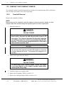
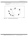
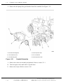
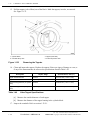
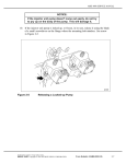
1
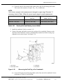
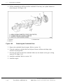
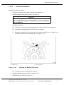
MBE4000 SERVICE MANUAL
1.9
CRANKSHAFT ASSEMBLY
The crankshaft is precision-forged with seven main bearings and eight custom-forged counter
weights, and a vibration damper at the front end. For an exploded view of the crankshaft, main
bearings, and main bearing caps, see Figure 1-42.
1. Crankshaft
5. Lower Bearing Shell (center)
2. Upper Bearing Shell(s)
6. Main Bearing Cap(s)
3. Upper Bearing Shell (center)
7. Main Bearing Cap (center)
4. Lower Bearing Shell(s)
8. Main Bearing Cap Bolt
Figure 1-42
Crankshaft, Main Bearings, and Main Bearing Caps
All information subject to change without notice.
(Rev. 3/04)
6SE412 0403 Copyright © 2006 DETROIT DIESEL CORPORATION
From Bulletin 1–MBE4000–06
1-57
1.9
CRANKSHAFT ASSEMBLY
1.9.1
Crankshaft Removal
Remove the crankshaft as follows:
FALLING ENGINE
To avoid injury from a falling engine, an adequate lifting
device with a spreader bar and sling should be used to lift
the engine. The sling and spreader bar should be adjusted
so the lifting hooks are vertical to prevent bending the lifter
brackets. To ensure proper weight distribution, all provided
lifter brackets must be used.
NOTICE:
A spreader bar must be used at all times in conjunction with the
front and rear lifter brackets to lift the EGR engine to ensure that
no engine damage will result. The brackets are designed to lift
vertically.
1. Remove the engine from the vehicle.
FALLING ENGINE
To avoid injury from a falling engine, ensure the engine
is securely attached to the engine overhaul stand before
releasing the lifting sling.
2. Mount the engine on an engine stand.
3. Remove the cylinder heads. Refer to section 1.2.1.
4. Remove the oil pan and oil pump. Refer to section 3.1.1. Refer to section 3.4.1.
5. Remove the flywheel and flywheel housing. Refer to section 1.12.1.
6. Remove the front cover housing. Refer to section 1.10.1.
7. Remove the pistons. Refer to section 1.17.1.
1-586
From Bulletin 1–MBE4000–06
(Rev. 3/04)
All information subject to change without notice.
6SE412 0403 Copyright © 2006 DETROIT DIESEL CORPORATION
MBE4000 SERVICE MANUAL
16. Install the cylinder heads. Refer to section 1.2.2.
FALLING ENGINE
To avoid injury from a falling engine, an adequate lifting
device with a spreader bar and sling should be used to lift
the engine. The sling and spreader bar should be adjusted
so the lifting hooks are vertical to prevent bending the lifter
brackets. To ensure proper weight distribution, all provided
lifter brackets must be used.
NOTICE:
A spreader bar must be used at all times in conjunction with the
front and rear lifter brackets to lift the EGR engine to ensure that
no engine damage will result. The brackets are designed to lift
vertically.
17. Remove the engine from the stand.
18. Install the engine in the vehicle.
1.9.2.1
Crankshaft Measuring and Inspection
Inspect the crankshaft as follows:
1. Remove the crankshaft. Refer to section 1.9.1.
2. Clean the crankshaft with a chamois.
3. Check the crankshaft for condition. If cracks or fissures are found, replace the crankshaft.
4. Using the hardness tester (000 589 53 21 00), test the hardness of the journals. Each
journal must pass the hardness test at two thirds of its circumference. If it doesn't, either
replace the crankshaft, or have it re-hardened.
[a]
Place a hard base underneath the bearing journal to be tested.
All information subject to change without notice.
(Rev. 3/04)
6SE412 0403 Copyright © 2006 DETROIT DIESEL CORPORATION
From Bulletin 1–MBE4000–06
1-65
1.9
CRANKSHAFT ASSEMBLY
[b]
Test hardness all the way around the journal circumference. Hardness must be 53 to
59 HRC as listed in Table 1-13.
Description
Specification in mm (inches)*
Main Bearing and Connecting Rod Journal Hardness
(Rockwell hardness)
53 to 59 HRC
Permissible Deviation From True of Crankshaft†
0.09 (0.004)
Permissible Out-Of-Round for Main and Connecting-Rod
Bearing Journals - When New reground
0.01 (0.0004)
Permissible Out-Of-Round for Main and Connecting-Rod
Bearing Journals - Wear Limit
0.02 (0.0008)
Fillet Radii of Main Bearing Journals
4.2-4.5 (0.165-0.177)
Fillet Radii of Connecting Rod Bearing Journals
3.7 - 4.0 (0.146 - 0.157)
Crown of Main Bearing Journals and Connecting-Rod
Journals
0.000-0.004 (0.0000-0.0002)
Main Bearing Outside Diameter (diameter of bearing
shell housing
111.000-111.022 (4.3701-4.3709)
Permissible Imbalance of Crankshaft‡ -at 400 rpm
0.6 N·cm (0.05 lb·in.)
* Except as otherwise noted.
†Measure with the crankshaft mounted on the outer main bearing journals.
‡With the pin for the flywheel installed, but without the flywheel, and with the crankshaft mounted on the outer bearings.
Table 1-13
Crankshaft Specifications
5. Measure the deviation from true of the crankshaft. If the deviation from true is greater
than 0.09 mm (0.004 inch), regrind the crankshaft.
[a]
Support the crankshaft on a stand, held by the two external journals.
[b]
Set up a dial gauge and holder on the center journal, with some preload on the gauge.
[c]
Set the dial gauge to "0" (zero).
[d]
Turn the crankshaft through one full revolution, and check the dial gauge. If the dial
gauge deviates by more than 0.09 mm (0.004 inch), regrind the crankshaft.
6. Check the crankshaft for dynamic balance. Permissible imbalance is listed in Table 1-13.
7. Using a micrometer, measure the diameters of the main journals and the connecting-rod
journals. Measure in both the vertical and horizontal directions on each journal.
Refer to section 1.9.2.2 for detailed procedures.
8. Comparing the two measurements taken above, check each crankshaft main and
connecting-rod journal for out-of-round.
If, for any one journal, the two measurements differ by more than 0.01 mm (0.0004 inch), regrind
the crankshaft.
If, for any one journal, the two measurements differ by more than 0.02 mm (0.0008 inch), replace
the crankshaft. Refer to section 1.9.1.
1-664
From Bulletin 1–MBE4000–06
(Rev. 3/04)
All information subject to change without notice.
6SE412 0403 Copyright © 2006 DETROIT DIESEL CORPORATION
MBE4000 SERVICE MANUAL
[b]
For the main bearing journal, note the outside diameter of the journal. Example:
Dj= 4.0850 inches.
[c]
From the value for the bearing shell diameter, subtract the value for the journal
diameter. This result is the radial play. Example: Ds— Dj = 0.0025 inch.
NOTE:
In the above example, both measurements belonged to repair stage "Undersize - 0.010
inch." Listed in Table 1-17 is the correct repair stage for each measurement.
11. Install the crankshaft into the crankcase. Refer to section 1.9.2.
FALLING ENGINE
To avoid injury from a falling engine, an adequate lifting
device with a spreader bar and sling should be used to lift
the engine. The sling and spreader bar should be adjusted
so the lifting hooks are vertical to prevent bending the lifter
brackets. To ensure proper weight distribution, all provided
lifter brackets must be used.
NOTICE:
A spreader bar must be used at all times in conjunction with the
front and rear lifter brackets to lift the EGR engine to ensure that
no engine damage will result. The brackets are designed to lift
vertically.
12. Install the engine in the vehicle.
1.9.2.3
Crankshaft End Play Checking
Check the crankshaft end play as follows:
1. Remove the crankshaft. Refer to section 1.9.1.
All information subject to change without notice.
(Rev. 3/04)
6SE412 0403 Copyright © 2006 DETROIT DIESEL CORPORATION
From Bulletin 1–MBE4000–06
1-77
1.9
CRANKSHAFT ASSEMBLY
2. Check the width of the center main bearing journal. If damage or cracks are present,
replace the crankshaft. See Figure 1-57.
Figure 1-57
1-78.
Measuring the Width of the Center Journal
F rom Bulletin 1–MBE4000–06
(Rev. 3/04)
All information subject to change without notice.
6SE412 0403 Copyright © 2006 DETROIT DIESEL CORPORATION
MBE4000 SERVICE MANUAL
3. Check the width of the center main bearing shell. If damage or cracks are present, replace
the crankshaft. See Figure 1-58.
Figure 1-58
Measuring the Width of the Center Main Bearing Shell
NOTE:
To obtain a correct value for crankshaft end play, the width of each bearing shell and its
corresponding journal must belong to the same repair stage (both must be "Standard,"
"Undersize - 0.020 inch," etc.).
4. Calculate the end play, or axial play, (fore-to-aft movement) of the crankshaft. If the
end play is less than 0.190 mm (0.0074 inch), or more than 0.322 mm (0.0127 inch) as
listed in Table 1-19, then replace the crankshaft.
Description
End Play (Axial Play) Measured at Center Bearing
Journal
Table 1-19
mm (inch)
0.190-0.322 (0.0074-0.0127)
Crankshaft End Play
[a]
For the center main bearing journal, note the width (thickness) of the bearing journal.
Example:Wm = 1.8120 inches.
[b]
For the center main bearing shell, note the width (thickness) of the bearing shell.
Example: Ws =1.8030 inches.
All information subject to change without notice.
(Rev. 3/04)
6SE412 0403 Copyright © 2006 DETROIT DIESEL CORPORATION
From Bulletin 1–MBE4000–06
1-78a
1.9
CRANKSHAFT ASSEMBLY
This page intentionally left blank.
1-78b
From Bulletin 1–MBE4000–06
(Rev. 3/04)
All information subject to change without notice.
6SE412 0403 Copyright © 2006 DETROIT DIESEL CORPORATION
MBE4000 SERVICE MANUAL
[c]
From the value for the journal width, subtract the value for the bearing shell width.
This result is the end play. Example: Wm— Ws= 0.0090 inch.
NOTE:
In the above example, both measurements belonged to repair stage "Standard." If
necessary, listed in Table 1-20are the correct repair stages for each measurement.
Size: mm (in.)
Center Bearing Shell Width:
mm (in.)
Center Bearing Journal
Width: mm (in.)
Standard
45.74-45.81 (1.801-1.804)
46.000-46.062 (1.8110-1.8135)
Undersize - 0.020 (0.50)
46.24-46.31 (1.820-1.823)
46.500-46.562 (1.8307-1.8331)
Undersize - 1.00 (0.040)
46.74-46.81 (1.840-1.843)
47.000-47.062 (1.8504-1.8528)
Table 1-20
Bearing Shell and Bearing Journal Width
5. Install the crankshaft. Refer to section 1.9.2.
6. Using a dial gauge and holder, measure the end play of the crankshaft. Measure at the
front end of the crankshaft, with the crankshaft fully installed and all the bearing caps
tightened to the correct torque. See Figure 1-59.
1. Dial Gauge
3. Crankshaft
2. Dial Gauge Holder
4. Screwdriver
Figure 1-59
[a]
Measuring the End Play of the Crankshaft
Set up a dial gauge and a dial gauge holder on the front end of the crankshaft. Set the
dial gauge to 5 mm (0.2 inch) preload.
All information subject to change without notice.
(Rev. 3/04)
6SE412 0403 Copyright © 2006 DETROIT DIESEL CORPORATION
From Bulletin 1–MBE4000–06
1-79
1.9
CRANKSHAFT ASSEMBLY
[b]
Move the crankshaft all the way forward by prying on one of the bearing caps, then
reset the dial gauge to "0" (zero).
[c]
Move the crankshaft all the way aft. Note the end play on the dial gauge.
[d]
If the end play does not correspond to the calculated amount (in the example above:
0.0090 inch), replace the crankshaft.
FALLING ENGINE
To avoid injury from a falling engine, an adequate lifting
device with a spreader bar and sling should be used to lift
the engine. The sling and spreader bar should be adjusted
so the lifting hooks are vertical to prevent bending the lifter
brackets. To ensure proper weight distribution, all provided
lifter brackets must be used.
NOTICE:
A spreader bar must be used at all times in conjunction with the
front and rear lifter brackets to lift the EGR engine to ensure that
no engine damage will result. The brackets are designed to lift
vertically.
7. Install the engine in the vehicle.
1.9.3
Crankshaft Gear Replacement
Replace the crankshaft gear as follows:
1-80
From Bulletin 1–MBE4000–06
(Rev. 3/04)
All information subject to change without notice.
6SE412 0403 Copyright © 2006 DETROIT DIESEL CORPORATION
MBE4000 SERVICE MANUAL
FALLING ENGINE
To avoid injury from a falling engine, an adequate lifting
device with a spreader bar and sling should be used to lift
the engine. The sling and spreader bar should be adjusted
so the lifting hooks are vertical to prevent bending the lifter
brackets. To ensure proper weight distribution, all provided
lifter brackets must be used.
NOTICE:
A spreader bar must be used at all times in conjunction with the
front and rear lifter brackets to lift the EGR engine to ensure that
no engine damage will result. The brackets are designed to lift
vertically.
1. Remove the engine from the vehicle and install on an engine stand.
2. Remove the flywheel housing. Refer to section 1.16.1.
3. Rotate the crankshaft until the marked gear tooth on the crankshaft gear is aligned between
the two similarly marked teeth on the camshaft gear.
All information subject to change without notice.
(Rev. 3/04)
6SE412 0403 Copyright © 2006 DETROIT DIESEL CORPORATION
From Bulletin 1–MBE4000–06
1-80a
1.9
CRANKSHAFT ASSEMBLY
4. Pull the crankshaft gear off the end of the crankshaft. If necessary, use a plastic hammer to
loosen the gear. See Figure 1-60.
1. Crankshaft
3. Crankshaft Gear
2. Guide Pin
Figure 1-60
Removing the Crankshaft Gear
5. Remove the crankshaft from the engine. Refer to section 1.9.1.
6. Clean the crankcase (cylinder block and oil pan). Remove all burrs and sharp edges
from the oil passage holes.
7. Press the gear onto the end of the crankshaft. Make sure the chamfer on the gear is facing
outward. See Figure 1-60.
8. Install the crankshaft. Refer to section 1.9.2.
9. Install the engine.
1-80ba
From Bulletin 1–MBE4000–06
(Rev. 3/04)
All information subject to change without notice.
6SE412 0403 Copyright © 2006 DETROIT DIESEL CORPORATION
MBE4000 SERVICE MANUAL
This page intentionally left blank.
All information subject to change without notice.
(Rev. 3/04)
6SE412 0403 Copyright © 2006 DETROIT DIESEL CORPORATION
From Bulletin 1–MBE4000–06
1-81
1.10
FRONT COVER HOUSING
1.10 FRONT COVER HOUSING
For an exploded view of the front cover housing, see Figure 1-61.
1. Vibration Damper
5. Cover Housing Gasket
2. Oil Deflector
6. Oil Pan
3. Front Radial Seal
7. Housing Mounting Bolt
4. Front Cover Housing
Figure 1-61
1.10.1
Front Cover Housing
Front Cover Housing Removal
Remove the front cover housing as follows:
1. Park the vehicle on a level spot, set the parking brakes, and chock the tires.
To avoid injury before starting and running the engine,
ensure the vehicle is parked on a level surface, parking
brake is set, and the wheels are blocked.
2. Tilt the hood.
3. Remove the front engine mounting bolts attaching the front cover housing to the front
crossmember.
1-82
From Bulletin 1–MBE4000–06
(Rev. 3/04)
All information subject to change without notice.
6SE412 0403 Copyright © 2006 DETROIT DIESEL CORPORATION
FALLING COMPONENT
To avoid injury from a falling component, ensure a proper
lifting device is used.
2. Install the flywheel over the guide pins (J–46172). Align the dowel on the crankshaft with
the guide hole in the flywheel (arrow). See Figure 1-67.
3. Install the engine cranking tool (J–46167) in the flywheel housing and secure with two
bolts. Insert the pin and make sure the tool is blocked. Refer to section 1.15.2.
Figure 1-67
Flywheel Alignment Mark
NOTE:
Verify the alignment of the crankshaft dowel with the guide hole in the flywheel.
4. With a light coating of engine oil, lubricate the threads of the ten multipoint socket-head
flywheel bolts.
All information subject to change without notice.
Copyright © DETROIT DIESEL CORPORATION
1-91
1.12
FLYWHEEL
5. Tighten the eight bolts in two stages. In each stage, use an alternate sequence to tighten
the bolts, as listed in Table 1-21.
Max. Shaft Length, mm (in.)
Tightening Stage
Torque Value, N·m (lb·ft)
77.0 (3.03)
Stage 1
200 (147.5)
77.0 (3.03)
Stage 2
90 degrees
Table 1-21
Tightening Stages, Flywheel Mounting Bolts
[a]
Install eight bolts to hold the flywheel in position.
[b]
Remove the two guide pins (J–46172) and install the two remaining bolts in their
place.
[c]
Tighten the bolts, in an alternate tightening sequence, 200 N·m (147.5 lb·ft).
[d]
Using the same tightening sequence, turn the flywheel bolts 90 degrees.
6. Remove the engine cranking tool (J–46167). Install the inspection cover on the flywheel
housing with two bolts. Tighten the bolts 25 N·m (18 lb·ft).
7. Install the crank angle position sensor into the flywheel housing. Refer to section 2.6.3.
8. Install the clutch on the flywheel.
9. Install the transmission.
1.12.3
Flywheel Inspection
Perform the following procedures for inspecting the flywheel.
1.12.3.1
Flywheel Inspection
Inspect the flywheel as follows:
1. Remove the flywheel. Refer to section 1.12.1.
2. Thoroughly clean the flywheel and check it for cracks, scoring, burned areas, or rough
spots.
1-92
From Bulletin 1–MBE4000–06
(Rev. 3/04)
All information subject to change without notice.
6SE412 0403 Copyright © 2006 DETROIT DIESEL CORPORATION
MBE4000 SERVICE MANUAL
1.16.1
Flywheel Housing Removal
Remove the flywheel housing as follows:
1. With the engine removed from the vehicle, remove the flywheel. Refer to section 1.12.1.
2. Remove the crank angle position sensor. Refer to section 2.6.3.
3. Remove the camshaft (TDC) sensor. Refer to section 1.22.3.
4. Remove the starter from the block.
5. Remove the crankcase breather from the flywheel housing.
6. Remove the flywheel housing mounting bolts. Then remove the flywheel housing from
the cylinder block. See Figure 1-78.
7. Remove and discard the flywheel housing gasket.
1.16.2
Flywheel Housing Installation
Install the flywheel housing as follows:
1. Check the flywheel housing for damage.
2. Install a new rear radial seal. Refer to section 1.8.2.
3. Using a suitable scraper, such as a putty knife, clean the mating surfaces of the cylinder
block and the flywheel housing. Remove any dirt or grease, and all traces of old sealant.
4. Coat the mating surfaces of the flywheel housing and the cylinder block with Loctite®
574 sealant.
5. Install a new flywheel housing gasket.
6. Put the flywheel housing onto the cylinder block, making sure that it clears the oil pan and
that the bolt holes line up.
7. Install the flywheel housing mounting bolts and tighten them 70 N·m (52 lb·ft).
8. Install the starter.
9. Install the crankcase breather on the flywheel housing.
10. Install the flywheel. Refer to section 1.12.2.
11. Install the camshaft (TDC) sensor. Refer to section 1.22.3.
12. Install the crank angle position sensor. Refer to section 2.6.3.
All information subject to change without notice.
(Rev. 3/04)
6SE412 0403 Copyright © 2006 DETROIT DIESEL CORPORATION
From Bulletin 1–MBE4000–06
1-105
1.16
FLYWHEEL HOUSING
FALLING ENGINE
To avoid injury from a falling engine, an adequate lifting
device with a spreader bar and sling should be used to lift
the engine. The sling and spreader bar should be adjusted
so the lifting hooks are vertical to prevent bending the lifter
brackets. To ensure proper weight distribution, all provided
lifter brackets must be used.
NOTICE:
A spreader bar must be used at all times in conjunction with the
front and rear lifter brackets to lift the EGR engine to ensure that
no engine damage will result. The brackets are designed to lift
vertically.
13. Install the engine in the vehicle.
1-106
From Bulletin 1–MBE4000–06
(Rev. 3/04)
All information subject to change without notice.
6SE412 0403 Copyright © 2006 DETROIT DIESEL CORPORATION
MBE4000 SERVICE MANUAL
1.17 PISTON, PISTON RING, AND CONNECTING ROD
The pistons are made of aluminum alloy with ring carriers and a shallow combustion chamber
recess. The pistons are cooled by oil spray nozzles. See Figure 1-79 for an exploded view of the
piston and connecting rod assembly.
1. Piston and Rings
5. Bearing Cap
2. Wrist Pin
6. Connecting Rod Stretch Bolt
3. Snap Ring
7. Bearing Shell
4. Connecting Rod
Figure 1-79
1.17.1
Piston Assembly (exploded view)
Piston Removal
Remove the piston assembly as follows:
All information subject to change without notice.
(Rev. 3/04)
6SE412 0403 Copyright © 2006 DETROIT DIESEL CORPORATION
From Bulletin 1–MBE4000–06
1-107
1.17
PISTON, PISTON RING, AND CONNECTING ROD
FALLING ENGINE
To avoid injury from a falling engine, an adequate lifting
device with a spreader bar and sling should be used to lift
the engine. The sling and spreader bar should be adjusted
so the lifting hooks are vertical to prevent bending the lifter
brackets. To ensure proper weight distribution, all provided
lifter brackets must be used.
NOTICE:
A spreader bar must be used at all times in conjunction with the
front and rear lifter brackets to lift the EGR engine to ensure that
no engine damage will result. The brackets are designed to lift
vertically.
1. Remove the engine from the vehicle.
NOTE:
The MBE4000 engine has individual heads for each cylinder. To remove one piston, do
these procedures step by step. To remove all the pistons, repeat each step in these
instructions, as applicable, for all six pistons.
2. Remove each cylinder head, as required. Refer to section 1.2.1.
3. Remove the oil pan. Refer to section 3.1.1.
NOTICE:
Do not damage the piston travel surface of the cylinder.
4. Using a plastic scraping tool, carefully scrape off any combustion residues from the
combustion area in the cylinder in order to avoid damage to the piston rings when the
piston is removed.
5. Install the engine cranking tool (J–46167). Refer to section 1.15.1.
1-108
From Bulletin 1–MBE4000–06
(Rev. 3/04)
All information subject to change without notice.
6SE412 0403 Copyright © 2006 DETROIT DIESEL CORPORATION
MBE4000 SERVICE MANUAL
6. Be sure the connecting rods and the bearing caps are marked so that they can be matched
for installation. See Figure 1-80.
1. Bearing Cap
Figure 1-80
2. Connecting Rod
Checking Rod and Bearing Cap Markings
All information subject to change without notice.
(Rev. 3/04)
6SE412 0403 Copyright © 2006 DETROIT DIESEL CORPORATION
From Bulletin 1–MBE4000–06
1-108a
1.17
PISTON, PISTON RING, AND CONNECTING ROD
7. Remove and inspect the oil spray nozzles. See Figure 1-81. Refer to section 3.2.1.
Replace them if damaged.
1. Oil Spray Nozzle
Figure 1-81
1-108b
2. Cylinder Liner
Location of Oil Spray Nozzle
From Bulletin 1–MBE4000–06
(Rev. 3/04)
All information subject to change without notice.
6SE412 0403 Copyright © 2006 DETROIT DIESEL CORPORATION
MBE4000 SERVICE MANUAL
15. Using a dial gauge and holder, measure the piston projection relative to crankcase top dead
center at all the pistons. See Figure 1-88.
1. Piston
2. Cylinder Liner
Figure 1-88
Piston Projection at Top Dead Center (TDC)
16. If the piston projection dimensions are not between 0.244 and 0.715 mm (0.0096 and
0.0281 inch), replace the piston. Listed in Table 1-25.
Description
mm (in.)
Piston Projection (from TDC)
Table 1-25
0.244 to 0.715 (0.0096 to 0.0281)
Piston Projection Specifications
17. Remove the engine cranking tool (J–46167).
NOTICE:
Be careful not to damage the oil spray nozzles. Damaged
oil spray nozzles could result in a loss of oil pressure and
cause engine damage.
18. Install the oil spray nozzles, as removed. Be sure they are seated and aligned correctly.
Refer to section 3.2.2.
19. Install the oil pan. Refer to section 3.1.2.
20. Install each cylinder head, as removed. Refer to section 1.2.2.
All information subject to change without notice.
(Rev. 3/04)
6SE412 0403 Copyright © 2006 DETROIT DIESEL CORPORATION
From Bulletin 1–MBE4000–06
1-115
1.17
PISTON, PISTON RING, AND CONNECTING ROD
FALLING ENGINE
To avoid injury from a falling engine, an adequate lifting
device with a spreader bar and sling should be used to lift
the engine. The sling and spreader bar should be adjusted
so the lifting hooks are vertical to prevent bending the lifter
brackets. To ensure proper weight distribution, all provided
lifter brackets must be used.
NOTICE:
A spreader bar must be used at all times in conjunction with the
front and rear lifter brackets to lift the EGR engine to ensure that
no engine damage will result. The brackets are designed to lift
vertically.
21. Install the engine in the vehicle.
1.17.3
Piston Ring Replacement
Replace the piston ring as follows:
1. Remove the piston. Refer to section 1.17.1.
2. Remove the rings, using suitable ring pliers. Remove the rings in order, starting from the
top of the piston down. See Figure 1-89. See Figure 1-90.
1-1163
From Bulletin 1–MBE4000–06
(Rev. 3/04)
All information subject to change without notice.
6SE412 0403 Copyright © 2006 DETROIT DIESEL CORPORATION
MBE4000 SERVICE MANUAL
1. Keystone Piston Ring (Groove I)
3. Double Chamfered Oil Control Ring with Garter
Spring (Groove III)
2. Taper Face Ring with Internal Angle (Groove II)
4. Piston
Figure 1-89
Piston Rings
1. Piston
Figure 1-90
2. Ring Pliers
Removing the Piston Rings
All information subject to change without notice.
(Rev. 3/04)
6SE412 0403 Copyright © 2006 DETROIT DIESEL CORPORATION
From Bulletin 1–MBE4000–06
1-117
1.17
PISTON, PISTON RING, AND CONNECTING ROD
3. Clean all the carbon from the ring grooves. Be sure the grooves are not damaged, and that
there are no burrs or combustion residue in the grooves.
4. Before installing the new rings, check the end gap. The correct end-gap measurements
are listed in Table 1-26.
Ring Designation
Groove
Gap When New
mm (in.)
Maximum End Gap
mm (in.)
Keystone
I
0.45 to 0.60
(0.018 to 0.024)
1.0 (.039)
Taper-Faced with Internal
Angle
II
0.40 to 0.55
(0.016 to 0.022)
1.0 (.039)
Double-Chamfered Oil
Control with Garter Spring
III
0.40 to 0.55
(0.016 to 0.022)
1.0 (.039)
Table 1-26
Piston Ring End-Gap Dimensions
NOTE:
Check the end gap of the upper two piston rings first. The garter spring must be removed
from the third (lowest) piston ring before you can measure its end gap.
[a]
Place each ring squarely into the combustion area of a cylinder liner or cylinder, then
measure the end gap, using a feeler gauge. See Figure 1-91.
Figure 1-91
[b]
1-1185
Checking the Ring End Gap
Remove the spring garter from the third (lowest) ring, then measure its gap in the
same way as the other two rings.
From Bulletin 1–MBE4000–06
(Rev. 3/04)
All information subject to change without notice.
6SE412 0403 Copyright © 2006 DETROIT DIESEL CORPORATION
MBE4000 SERVICE MANUAL
14. Inspect the valve springs. Check the springs for correct pressure, using the values
listed in Table 1-43. If damaged, replace the springs.
Description
mm (in.)
Length, Without Load
69.7 (2.74)
Length, Under Load of 382-418 N (86-94 lbf)
49 (1.9)
Length, Under Load of 644-706 N (145-159 lbf)
37 (1.5)
Diameter of Spring Wire
4.2 (0.17)
Outside Diameter of Spring Coil
28.9 (1.14)
Inside Diameter of Spring Coil
24.5-24.9 (0.96-0.98)
Table 1-43
1.19.6
Spring Specifications, Intake and Exhaust Valves
Valve Installation
Install the intake and exhaust valves as follows:
1. Lubricate each valve with a light coating of engine oil.
2. Install the valves in order, as marked on removal.
NOTE:
Always replace the valve stem seal if the valve has been removed. Check the seal to
make sure it is correctly seated on the valve guide. Refer to section 1.19.7.
3. Install new valve stem seals. Refer to section 1.19.7.
4. Using the adaptor/remover, (J–46173), install the spring bases, springs, spring retainers,
and collets. Check the collets to be sure they are locked in place.
5. Remove the adaptor/remover, (J–46173), from the cylinder head.
6. Install the cylinder head. Refer to section 1.2.2.
1.19.7
Valve Stem Seal Replacement
Replace the valve stem seal as follows:
NOTE:
Always replace the valve stem seal if the valve has been removed.
1. Remove the cylinder head from the engine. Refer to section 1.2.1.
NOTE:
Use care during removal to not damage the valve guides and valve stems.
All information subject to change without notice.
(Rev. 3/04)
6SE412 0403 Copyright © 2006 DETROIT DIESEL CORPORATION
From Bulletin 1–MBE4000–06
1-159
1.19
VALVES
2. Remove the collets, spring retainer, valve spring, and spring base. See Figure 1-123.
1. Valve Stem Seal
3. Valve Guide
2. Valve Stem
Figure 1-123
Valve Stem Seal Replacement
3. Remove the valve stem seal. Do not remove the valve.
4. Lubricate the valve stem and valve stem seal installer/protector (J–46174) with a light
coating of clean engine oil.
NOTE:
The installer prevents the groove on the valve stem from damaging the seal.
5. Push the valve stem seal installer/protector (J–46174) over the valve stem until it makes
contact with the valve.
6. Slide the seal over the installer/protector and the valve stem. Using fingers, press the seal
into place until the seal seats on the valve guide.
NOTE:
Check the seal to make sure it is correctly seated on the valve guide.
7. Remove the installer from the valve stem seal and the valve.
8. Install the collets, spring retainer, valve spring and spring base, as removed.
9. Repeat the procedure for the other valves.
10. Install the cylinder head. Refer to section 1.2.2.
1-1607
From Bulletin 1–MBE4000–06
(Rev. 3/04)
All information subject to change without notice.
6SE412 0403 Copyright © 2006 DETROIT DIESEL CORPORATION
MBE4000 SERVICE MANUAL
1.20.2
Valve Installation in the EGR Engine
Perform the following steps in installing the valves in the EGR engine:
1. Install the valve stem sealing ring in the valve guide in the cylinder head.
2. Lubricate each valve with a light coating of engine oil.
3. Install the valves in order, as marked on removal.
NOTE:
In the EGR engine, always replace the valve stem seal and valve stem sealing ring if
the valve has been removed. Check the valve stem seal to make sure it is correctly
seated on the valve guide.
4. Using valve stem seal installer/protector (J–46174), install new valve stem seals and seat
the valve stem seal with valve stem seal installer (J–46184). Refer to section 1.20.3.
5. Using the adaptor (J–46173), install the spring seats, springs, spring retainers, and collets
(keepers). Check the keepers to be sure they are locked in place.
6. Remove the adaptor (J–46173), from the cylinder head.
7. Install the cylinder head.
1.20.3
Valve Stem Seal and Valve Stem Sealing Ring Replacement in
the EGR Engine
Replace the valve stem seal and valve stem sealing ring as follows:
NOTE:
In the EGR engine, always replace the valve stem seal and valve stem sealing ring
if the valve has been removed.
1. Remove the cylinder head from the engine.
NOTE:
Use care during removal to not damage the valve guides and valve stems.
2. Remove the keeper, spring retainer, valve spring, and spring seat.
3. Remove the valve stem seal and discard.
4. Remove the valve.
5. Remove the valve stem sealing ring and discard. Repeat procedure for all remaining
valves.
6. Clean all parts before reinstalling components.
7. Install the valve stem sealing ring in the valve guide and then install the valve in the head.
Repeat procedure for all remaining valves.
All information subject to change without notice.
(Rev. 3/04)
6SE412 0403 Copyright © 2006 DETROIT DIESEL CORPORATION
From Bulletin 1–MBE4000–06
1-163
1.20
EGR VALVES
8. Lubricate the valve stem and valve stem seal installer/protector (J–46174) with a light
coating of clean engine oil.
1. Valve Stem Seal
3. Valve Guide
2. Valve Stem
4. Valve Stem Sealing Ring (installed)
Figure 1-126
Valve Stem Seal and Sealing Ring Replacement
NOTE:
The installer/protector prevents the groove on the valve stem from damaging the valve
stem seal.
9. Push the valve stem seal installer/protector (J–46174) over the valve stem until it makes
contact with the valve.
10. Slide the valve stem seal over the installer/protector and the valve stem. Using fingers,
press valve stem seal into place until the seal seats on the valve guide.
11. Remove the valve stem seal installer/protector (J–46174).
12. Using valve stem seal installer (J–46184) and the appropriate hammer, drive the valve
stem seal on the guide.
NOTE:
Check the seal to make sure it is correctly seated on the valve guide.
13. Remove the installer from the valve stem seal and the valve.
14. Install the keeper, spring retainer, valve spring and spring seat, as removed.
15. Repeat the procedure for the other valves.
1-1641
From Bulletin 1–MBE4000–06
(Rev. 3/04)
All information subject to change without notice.
6SE412 0403 Copyright © 2006 DETROIT DIESEL CORPORATION
MBE4000 SERVICE MANUAL
3. Inspect each pushrod to be sure it is correctly seated in its tappet. Replace any pushrods
that are warped, are not correctly seated, or are not the correct length as listed in Table
1-48.
Description
Stage
Specification mm (in.)
Outside Diameter of Valve Tappets
Normal
29.931-29.952
(1.1784-1.1792)
Outside Diameter of Valve Tappets
Repair Stage I
30.444-30.465
(1.1986-1.1994)
Diameter of Tappet Seats (in cylinder
block)
Normal
30.000-30.021
(1.1811-1.1819)
Diameter of Tappet Seats (in cylinder
block)
Repair Stage I
30.500-30.525
(1.2008-1.2018)
Total Length of Pushrods
Maximum Pushrod Warpage
Maximum Length of Rocker Arm Mounting Bolts
Table 1-48
345.0-346.5 mm (13.58-13.64)
0.5 mm (0.02)
91 mm (3.6)
Rocker Arm Specifications
4. Install the rocker arm assembly.
[a]
Position the rocker arm assembly on the cylinder head, as removed.
[b]
Install the mounting bolts in the holes in the cylinder head.
[c]
Tighten each mounting bolt 60 N·m (44 lb·ft). Final angular tightening: 90 degrees.
5. Adjust the valve lash. Refer to section 1.19.3.
6. Install the cylinder head cover on each cylinder head. Refer to section 1.1.2.
All information subject to change without notice.
(Rev. 3/04)
6SE412 0403 Copyright © 2006 DETROIT DIESEL CORPORATION
From Bulletin 1–MBE4000–06
1-169
1.22
CAMSHAFT AND CAMSHAFT SENSOR
1.22 CAMSHAFT AND CAMSHAFT SENSOR
The camshaft is made of induction-hardened steel and has seven main bearings. Each cylinder has
cams for intake and exhaust valves and a unit pump.
1.22.1
Camshaft Removal
Remove the camshaft as follows:
NOTE:
Before removing the camshaft, clean the engine to prevent road dirt, grease, or other
foreign matter from contaminating the exposed gears and other engine parts.
1. Drain the engine oil.
FALLING ENGINE
To avoid injury from a falling engine, an adequate lifting
device with a spreader bar and sling should be used to lift
the engine. The sling and spreader bar should be adjusted
so the lifting hooks are vertical to prevent bending the lifter
brackets. To ensure proper weight distribution, all provided
lifter brackets must be used.
NOTICE:
A spreader bar must be used at all times in conjunction with the
front and rear lifter brackets to lift the EGR engine to ensure that
no engine damage will result. The brackets are designed to lift
vertically.
2. Remove the engine from the vehicle.
FALLING ENGINE
To avoid injury from a falling engine, ensure the engine
is securely attached to the engine overhaul stand before
releasing the lifting sling.
3. Install the engine on an engine stand.
4. Remove the unit pumps. Refer to section 2.1.1.
5. Remove the vibration damper. Refer to section 1.11.1.
1-170
From Bulletin 1–MBE4000–06
(Rev. 3/04)
All information subject to change without notice.
6SE412 0403 Copyright © 2006 DETROIT DIESEL CORPORATION
MBE4000 SERVICE MANUAL
6. Remove the fan support.
7. Remove the eight mounting bolts attaching the camshaft front cover to the cylinder block.
See Figure 1-130.
Figure 1-130
Removing the Camshaft Front Cover
All information subject to change without notice.
(Rev. 3/04)
6SE412 0403 Copyright © 2006 DETROIT DIESEL CORPORATION
From Bulletin 1–MBE4000–06
1-171
1.22
CAMSHAFT AND CAMSHAFT SENSOR
8. Remove the fuel pump drive gear from the front of the camshaft. See Figure 1-131.
1. Drive Gear Mounting Bolt
4. Fuel Pump Drive Gear
2. Front Camshaft Cover
5. Front of Camshaft
3. Cover Mounting Bolt
6. Fuel Pump Driven Gear
Figure 1-131
Camshaft Assembly
9. Remove the rocker arm assembly and pushrods. Refer to section 1.21.1.
10. Turn the engine on the stand until it is upside down.
11. Remove the oil pan. Refer to section 1.16.1.
1-1729
From Bulletin 1–MBE4000–06
(Rev. 3/04)
All information subject to change without notice.
6SE412 0403 Copyright © 2006 DETROIT DIESEL CORPORATION
MBE4000 SERVICE MANUAL
12. Remove the flywheel housing. Refer to section 1.16.1.
NOTICE:
Do not damage the camshaft bearings in the crankcase. If
the camshaft bearings are damaged, the crankcase will have
to be replaced.
13. Attach the camshaft guide tool (J-46183) to the front of the camshaft. See Figure 1-132.
1. Front of Camshaft
Figure 1-132
Attaching the Camshaft Guide Tool
14. From the gear end (rear of the engine), carefully remove the camshaft from the block.
See Figure 1-132.
All information subject to change without notice.
(Rev. 3/04)
6SE412 0403 Copyright © 2006 DETROIT DIESEL CORPORATION
From Bulletin 1–MBE4000–06
1-173
1.22
CAMSHAFT AND CAMSHAFT SENSOR
15. Pull the tappets (valve lifters) out of the block. Mark the tappets, in order, as removed.
See Figure 1-133.
1. Cylinder Block
3. Tappet (valve lifter)
2. Camshaft Entry Hole
4. Fuel Pump Driven Gear
Figure 1-133
Removing the Tappets
16. Clean and inspect the tappets. Replace the tappets if there are signs of damage or wear, or
if any of the measurements do not meet the specifications listed in Table 1-49.
Description
Repair Stage
Specifications, mm (in.)
Tappet Outside Diameter
Standard
29.931-29.952 (1.1784-1.1792)
Tappet Outside Diameter
Repair Stage I
30.444-30.465 (1.1986-1.1994)
Tappet Housing Diameter (in cylinder
block)
Standard
30.000-30.021 (1.1811-1.1819)
Tappet Housing Diameter (in cylinder
block)
Repair Stage I
30.500-30.525 (1.2008-1.2018)
Table 1-49
Valve Tappet Specifications
[a]
Measure the outside diameter of each tappet.
[b]
Measure the diameter of the tappet housing in the cylinder block.
17. Inspect the camshaft. Refer to section 1.22.2.1.
1-174
From Bulletin 1–MBE4000–06
(Rev. 3/04)
All information subject to change without notice.
6SE412 0403 Copyright © 2006 DETROIT DIESEL CORPORATION
MBE4000 SERVICE MANUAL
1.22.2
Camshaft Installation
Install the camshaft as follows:
1. Lubricate the tappets with a light coating of clean engine oil.
2. Install the tappets in the block, in order, as removed.
NOTICE:
Do not damage the camshaft bearings in the crankcase. If
the camshaft bearings are damaged, the crankcase will have
to be replaced.
3. Install the camshaft.
[a]
Lubricate the cams and camshaft journals with a light coating of clean engine oil.
[b]
Attach the camshaft guide tool (J-46183) to the camshaft.
[c]
Rotate the camshaft until the marked gear teeth on the camshaft gear are aligned with
the marked tooth on the crankshaft gear. See Figure 1-134.
1. Camshaft Gear
Figure 1-134
[d]
2. Crankshaft Gear
Aligning the Marked Gear Teeth
Carefully insert the camshaft into the block.
4. Install the flywheel housing. Refer to section 1.16.2.
5. Install the oil pan. Refer to section 3.1.2.
All information subject to change without notice.
(Rev. 3/04)
6SE412 0403 Copyright © 2006 DETROIT DIESEL CORPORATION
From Bulletin 1–MBE4000–06
1-175
1.22
CAMSHAFT AND CAMSHAFT SENSOR
6. Install the fuel pump drive gear on the front of the camshaft, as removed. Torque the
bolts to 60 N·m (44 lb·ft.)
7. Turn the engine on the stand until it is right side up.
8. Install the unit pumps. Refer to section 2.1.2.
9. Install the camshaft front cover on the cylinder block, as removed. Torque the mounting
bolts to 50 N·m (37 lb·ft.)
10. Install the fan support.
11. Install the vibration damper. Refer to section 1.11.2.
12. Lubricate the pushrods with a light coating of clean engine oil. Install the pushrods and
the rocker arm assembly. Refer to section 1.21.4.
FALLING ENGINE
To avoid injury from a falling engine, an adequate lifting
device with a spreader bar and sling should be used to lift
the engine. The sling and spreader bar should be adjusted
so the lifting hooks are vertical to prevent bending the lifter
brackets. To ensure proper weight distribution, all provided
lifter brackets must be used.
NOTICE:
A spreader bar must be used at all times in conjunction with the
front and rear lifter brackets to lift the EGR engine to ensure that
no engine damage will result. The brackets are designed to lift
vertically.
13. Remove the engine from the stand and install it on the vehicle.
14. Fill the engine with oil.
1.22.2.1
Camshaft Inspection
Inspect the camshaft as follows:
NOTE:
To get a correct hardness reading, it is critical to place a hard base below the cam or
bearing journal.
1-1763
From Bulletin 1–MBE4000–06
(Rev. 3/04)
All information subject to change without notice.
6SE412 0403 Copyright © 2006 DETROIT DIESEL CORPORATION