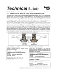
1
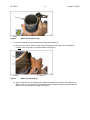
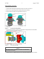
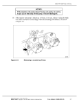
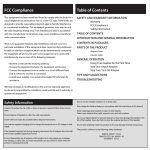
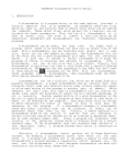
No.: 06 TS - 22
August 17, 2006
TO:
Service Locations
FROM:
Technical Support
SUBJECT:
REMAN MBE 4000 Turbo Brake Assembly
ISSUE
A new service assembly (P/N: R4571401206) is now available to install a REMAN MBE 4000 brake
assembly, see Figure 1, No.1. This assembly can be used to address engines with braking performance
complaints without replacing the complete turbo brake assembly.
1.
Brake Assembly
Figure 1
2.
Turbocharger
REMAN Turbo Brake Assembly
Please reference 18SP635 for additional kit information.
NOTE:
Prior to performing a brake assembly repair, all other possible causes for braking performance
concerns should be reviewed. Some causes are:
• Sliding Sleeve Pneumatic Actuator
o Air Supply
o Internal Damage to Pneumatic Actuator
o Bent Bracket
o Linkage Adjustment
• Software Calibration
• Constant Throttle
o CTV Solenoid
o Wiring
o Supply Line
Detroit Diesel Corporation 13400 Outer Drive, West / Detroit, Michigan 48239-4001
DA 1
06 TS-22
-2-
August 17, 2006
TURBO BRAKE ASSEMBLY REMOVAL PROCEDURE
Remove the turbocharger from the engine as follows:
PERSONAL INJURY
To avoid injury before starting and running the engine, ensure the
vehicle is parked on a level surface, parking brake is set, and the
wheels are blocked.
1. Apply the parking brake, chock the wheels, and perform any other applicable safety steps.
2. Disconnect vehicle battery power.
3. Remove the exhaust pipe from the turbocharger. Refer to the applicable vehicle service manual.
4. Remove the turbocharger inlet air pipe. Refer to the applicable vehicle service manual.
5. Remove the oil feed and return pipes from the turbocharger. Refer to the MBE 4000
Service Manual (6SE412).
6. Disconnect the turbocharger speed sensor harness connector. Refer to the MBE 4000
Service Manual (6SE412).
7. Disconnect the turbocharger wastegate and sliding sleeve air lines. Refer to the applicable
vehicle service manual.
8. Remove the turbocharger from the exhaust manifold and place the turbocharger on a bench.
Refer to the MBE 4000 Service Manual (6SE412).
Prior to disassembly of the turbo brake assembly, a routine inspection of the turbocharger should be
completed. Areas of concern could include:
•
•
•
•
Evidence of foreign objects entering and exiting the turbocharger
Evidence of restricted air flow
Evidence of lack of lubrication
Evidence of turbine or compressor wheel damage
TURBO BRAKE DISASSEMBLY PROCEDURE
Disassemble the turbo brake as follows:
1. Remove the clevis pin from the ball socket on the sliding sleeve actuator and discard.
2. Using a large screw driver or pry bar, disconnect the sliding sleeve actuator ball socket from the
sliding sleeve lever.
3. Inspect the sliding sleeve actuator for damage or binding and try to move the sliding sleeve lever.
This is used as a general inspection and may pinpoint the area of concern.
4. Remove the two bolts (1) and v-band clamp (3) from the exhaust bypass pipe (2). Discard the two
bolts (1), but save pipe and clamp for reinstallation. See Figure 2.
06 TS-22
-3-
August 17, 2006
5. Remove the four (4) nuts holding the brake assembly to the housing and discard. See Figure 2.
1.
2.
Bolt (2 qty.)
Exhaust Bypass Pipe
Figure 2
3.
4.
V-Band Clamp
Nut (4 qty.)
Exhaust Bypass Pipe and Brake Assembly Nuts
6. Separate the assembly from the turbocharger housing. Set the turbocharger horizontally on a
sturdy table. Protect the speed sensor and wiring from damage.
a) Using a brass hammer, tap the turbocharger housing equally on two sides until a small gap is
generated around the mating surface of the brake assembly and turbocharger housing. Do
NOT hit the exhaust pipe connecting flange. See Figure 3.
b) Once a gap is generated, use a large screwdriver or pry bar to apply even leverage 180° apart
to separate the brake from the turbocharger housing. See bold arrows in Figure 3. Try to keep
the brake assembly as straight as possible when removing.
1.
Exhaust Pipe Connecting Flange
Figure 3
Leverage Points
NOTE:
During most disassemblies the matrix usually stays in the turbocharger housing due to tight tolerance,
and a slight build up of rust. See Figure 4.
06 TS-22
1.
-4-
August 17, 2006
Matrix
Figure 4
Matrix Still Inside Housing
7. To remove the Matrix from the turbocharger housing do the following:
a) Use an emery cloth to clean the edge of the turbocharger housing just above the Matrix lip.
Do NOT use a die grinder or a powered sander. See Figure 5.
1.
Housing
Figure 5
2.
Matrix Lip
Matrix Lip and Housing
b) Apply a small amount of penetrating oil just above the Matrix lip around the entire radius and
allow it to set for a few minutes. The penetrating oil will seep down along the walls allowing the
Matrix to be removed without damage. See Figure 6.
06 TS-22
Figure 6
-5-
August 17, 2006
Applying Penetrating Oil to Matrix Lip
NOTICE:
If the Matrix will not turn by hand after penetrating oil has been applied,
use a non marring strap wrench near the base to provide extra
leverage. Do NOT hit the side of the Matrix. A rocking motion can cause
damage to the Matrix or the turbine blades. See Figure 7.
Figure 7
Broken Matrix (separated)
c) Grab the Matrix with two hands and rotate it back and forth while pulling straight up. If the
Matrix binds up, lightly tap the TOP with a rubber mallet to re-seat it in the bore. Re-inspect
the housing bore for a lip and remove if necessary. Continue the process until the Matrix
is removed. See Figure 8.
06 TS-22
-6-
August 17, 2006
Figure 8
Matrix Removal
8. Do the following to inspect the turbine blades and housing for wear:
a) Inspect the turbine blades for wear, cracks, chips, or evidence of foreign material entering the
turbocharger. See Figure 9.
Figure 9
Checking Turbine Blades for wear
b) Inspect the inside of the housing for single or multiple cracks. The housing can ONLY be
reused if the cracks do not intersect. See Figure 10.
1.
Single Crack (No intersecting cracks – reuseable)
Figure 10
2. Multiple Cracks (Intersecting cracks – non- reusable)
Intersecting vs. Non-Intersecting Cracks
9. Use an emery cloth and clean all mating surfaces between the housing and the new
brake assembly.
06 TS-22
-7-
August 17, 2006
BRAKE ASSEMBLY PROCEDURE
Assemble the brake as follows:
1. Place the brake assembly and turbocharger housing on their sides, see Figure 12.
2. Remove the tie wrap holding the Matrix together with the brake assembly.
3. Ensure the Matrix is seated over the guide baffle. See Figure 11.
1.
2.
Non-seated Matrix
Seated Matrix
Figure 11
3.
Guide Baffle
Non-Seated and Seated Matrix
4. Ensure the brake assembly is parallel to the turbocharger housing and slide the two assemblies
together until they are fully seated. See Figure 12.
1.
Brake Assembly
Figure 12
2.
Turbocharger
Turbo Brake Assembly
NOTICE:
Due to the tight tolerance of the Matrix to the housing, care must be taken
not to damage either assembly.
5. Install and torque in a diagonal sequence the four turbo brake assembly nuts to 40 N·m (29 lb-ft).
06 TS-22
-8-
August 17, 2006
6. Install the exhaust bypass tube flange to the brake assembly using two M8 X 16 bolts and torque to
30 N·m (22 lb-ft).
7. Install the opposite end of the exhaust bypass tube to the turbocharger housing and torque the
v-band clamp bolt to 5-7 N·m (4-5 lb-ft).
8. Connect the turbocharger to the exhaust manifold. Refer to the MBE 4000 Service Manual
(6SE412).
9. Connect the turbocharger wastegate and sliding sleeve air lines. Refer to the applicable vehicle
service manual.
10. Connect the turbocharger speed sensor harness connector.
11. Connect the oil feed and return pipes to the turbocharger. Refer to the MBE 4000
Service Manual (6SE412).
12. Connect the turbocharger inlet air pipe. Refer to the MBE 4000 Service Manual (6SE412).
13. Connect the exhaust pipe to the turbocharger. Refer to the applicable vehicle service manual.
14. Connect vehicle battery power.
PERSONAL INJURY
Diesel engine exhaust and some of its constituents are known to the
State of California to cause cancer, birth defects, and other reproductive
harm.
• Always start and operate an engine in a well ventilated area.
• If operating an engine in an enclosed area, vent the exhaust to the
outside.
• Do not modify or tamper with the exhaust system or emission control
system.
15. Start engine and check for air or oil leaks.
CONTACT INFORMATION
Please contact the DDC Customer Support Center at 313-592-5800 if you have any questions.