1
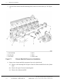
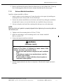
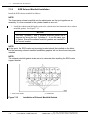
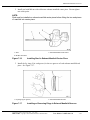
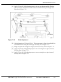
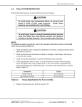
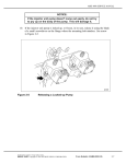
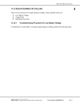
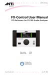
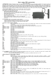
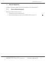
MBE4000 SERVICE MANUAL
7.1
EXHAUST MANIFOLD
Perform the following procedures for removal and installation of the exhaust manifold:
7.1.1
Exhaust Manifold Removal
Remove the exhaust manifold as follows:
1. Disconnect the batteries and tilt the hood.
2. Remove the turbocharger from the exhaust manifold. Refer to section 6.3.2.
All information subject to change without notice.
(Rev. 0403)
6SE412 0403 Copyright © 2005 DETROIT DIESEL CORPORATION
From Bulletin 7–MBE-4000–05
7-3
7.1
EXHAUST MANIFOLD
3. Loosen all the exhaust manifold mounting bolts, but do not remove them yet. See Figure
7-1.
1. Exhaust Manifold
4. Spacer
2. Mounting Bolt
5. Gasket
3. Turbocharger
6. Cylinder Heads
Figure 7-1
Exhaust Manifold Removal and Installation
4. Remove the exhaust manifold components from each cylinder head.
[a]
Remove each mounting bolt and spacer from the exhaust manifold and each cylinder
head.
[b]
Remove the spacer from each mounting bolt.
[c]
Remove the exhaust manifold.
(Rev. 0403)
7-4
From Bulletin 7–MBE-4000–05
All information subject to change without notice.
6SE412 0403 Copyright © 2005 DETROIT DIESEL CORPORATION
MBE4000 SERVICE MANUAL
5. Remove and discard the gaskets from the exhaust port on each cylinder head. Clean any
bits of adhering gasket material from the exhaust manifold and the exhaust ports.
7.1.2
Exhaust Manifold Installation
Install the exhaust manifold as follows:
1. Install a gasket on each exhaust port. Fasten the gasket to the engine by installing one
mounting bolt on the forward side of each exhaust port.
2. Position the exhaust manifold next to the heads, and install it by sliding the manifold to
the right until it comes to rest on the bolts that were installed in the previous step.
3. Line up each gasket and install the remaining bolt and spacer on each exhaust port.
NOTE:
Make sure that each gasket is properly aligned before tightening the mounting bolts on
that exhaust port.
4. Tighten each of the mounting bolts to 50 N·m (37 lb·ft).
5. Install the turbocharger on the mounting studs on the exhaust manifold.
Refer to section 6.3.3.
6. Connect the batteries and lower the hood.
PERSONAL INJURY
Diesel engine exhaust and some of its constituents are
known to the State of California to cause cancer, birth
defects, and other reproductive harm.
□ Always start and operate an engine in a well ventilated
area.
□ If operating an engine in an enclosed area, vent the
exhaust to the outside.
□ Do not modify or tamper with the exhaust system or
emission control system.
7. Start the engine and make sure there is oil pressure. Shut down the engine and check
for leaks.
All information subject to change without notice.
(Rev. 0403)
6SE412 0403 Copyright © 2005 DETROIT DIESEL CORPORATION
From Bulletin 7–MBE-4000–05
7-5
7.2
EXHAUST BRAKE ASSEMBLY
7.2
EXHAUST BRAKE ASSEMBLY
Engine braking is controlled by a pneumatically-operated exhaust brake on the turbocharger and
by a constant-throttle system. For greater braking power, an optional turbo brake is available.
7.2.1
Exhaust Brake Assembly Removal
Remove the exhaust brake assembly as follows:
1. Disconnect the batteries.
PERSONAL INJURY
To avoid injury before starting and running the engine,
ensure the vehicle is parked on a level surface, parking
brake is set, and the wheels are blocked.
2. Chock the rear tires and tilt the hood.
3. To gain access to the exhaust brake, remove the air cleaner.
PERSONAL INJURY
To avoid injury, never remove any engine component while
the engine is running.
PERSONAL INJURY
To avoid injury from the sudden release of a high-pressure
hose connection, wear a face shield or goggles.
4. Remove the exhaust brake compressed-air line from the exhaust brake cylinder.
(Rev. 0403)
7-6
From Bulletin 7–MBE-4000–05
All information subject to change without notice.
6SE412 0403 Copyright © 2005 DETROIT DIESEL CORPORATION
MBE4000 SERVICE MANUAL
10. Remove the fey rings (2 in each groove) from the two grooves of each exhaust manifold
end piece. See Figure 7-13.
1. Fey Ring
Figure 7-13
2. Exhaust Manifold Grooves
Installing or Removing Rings in Exhaust Manifold Grooves
NOTE:
EGR cooler and cooler bracket will need to be removed before removing the exhaust
manifold gaskets. Refer to section 7.4.1.
11. Remove exhaust manifold three-piece gasket from cylinder heads. See Figure 7-14.
1. Three-Piece Gasket
Figure 7-14
2. Guide Studs
Removal of Exhaust Manifold Gaskets
All information subject to change without notice.
(Rev. 0403)
6SE412 0403 Copyright © 2005 DETROIT DIESEL CORPORATION
From Bulletin 7–MBE-4000–05
7-21
7.3
EGR EXHAUST MANIFOLD
7.3.2
EGR Exhaust Manifold Installation
Install the EGR exhaust manifold as follows:
NOTE:
The three-piece exhaust manifold and its related parts are first put together as an
assembly; it is then mounted to the cylinder heads as one unit.
1. Install the exhaust manifold guide studs to the cylinder head and mount the three exhaust
manifold gaskets. See Figure 7-15.
NOTICE:
The front, cylinders 1 and 2, exhaust manifold gasket has a
diagonal cut along the end. Cylinders 3 – 6 use the same type
of gasket. Ensure the exhaust manifold gaskets are installed in
the correct location.
NOTE:
At this point, the EGR cooler and mounting bracket should be installed on the block,
but the remaining exhaust manifold installation graphics will not show these two parts
installed.
NOTE:
The exhaust manifold gasket studs are to be removed after installing the EGR cooler
support bracket.
1. Three-Piece Gasket
Figure 7-15
2. Guide Studs
Installation of Exhaust Manifold Gaskets
(Rev. 0403)
7-22
From Bulletin 7–MBE-4000–05
All information subject to change without notice.
6SE412 0403 Copyright © 2005 DETROIT DIESEL CORPORATION
MBE4000 SERVICE MANUAL
2. Install stud with M8 nut with collar onto exhaust manifold center piece. Do not tighten
nut at this point.
NOTE:
Stud must be installed on exhaust manifold center piece before fitting the two end pieces
of manifold into center piece.
1. Stud
3. Exhaust Manifold Center Piece
2. M8 Nut with Collar
Figure 7-16
Installing Stud in Exhaust Manifold Center Piece
3. Install the fey rings (2 in each groove) in the two grooves of each exhaust manifold end
piece. See Figure 7-17.
1. Fey Rings (2 per groove)
Figure 7-17
2. Exhaust Manifold Grooves
Installing or Removing Rings in Exhaust Manifold Grooves
All information subject to change without notice.
(Rev. 0403)
6SE412 0403 Copyright © 2005 DETROIT DIESEL CORPORATION
From Bulletin 7–MBE-4000–05
7-23
7.3
EGR EXHAUST MANIFOLD
4. Fit fey-ring ends of exhaust manifold pieces into center part of exhaust manifold. Do not
use lubricant. See Figure 7-12.
5. Bolt upper heat shield to exhaust manifold using the six mounting bolts (M8 x 12mm).
Finger-tighten all of the bolts, but torque the first bolt nearest the front part of the manifold
to 25 N·m (18 lb·ft).
NOTE:
Upper heat shield bolt that is closest to front of engine is torqued before assembly is
attached to engine due to impossible access after attachment to engine.
6. Bolt the lower heat shield to the upper heat shield with one captured bolt and washer
(M8 x 12mm). Torque to 25 N·m (18 lb·ft).
7. Install the entire exhaust manifold assembly onto the cylinder heads by lifting the right side
(or front) into place first, followed by the left (or rear). Install all exhaust manifold bolts,
and then torque all 12 mounting bolts to 50 N·m (38 lb·ft), using a crisscross sequence.
8. Torque remaining three mounting bolts (captured bolt and washer type) of the lower heat
shield to the exhaust manifold. Torque to 25 N·m (18 lb·ft).
9. Torque remaining five mounting bolts (captured bolt and washer type) of the upper heat
shield to the exhaust manifold. Torque to 25 N·m (18 lb·ft).
10. Install the fey rings (4 per groove) on the gas inlet pipe leading to exhaust manifold center
piece. Do not use lubricant.
11. Gently push gas inlet pipe into center exhaust manifold piece. Do not use lubricant.
12. Push gas inlet pipe of heat exchanger into throttle valve. Tighten screw at bottom of
positioning clamp on throttle valve assembly. Clamp must be tightened to 10 N·m (7 lb·ft)
after stud adjustment. Refer to step 14.
13. Screw the nut onto stud installed in exhaust manifold. Fit stud in the bracket that is
attached to the gas inlet pipe. Attach a nut to the outer edge of bracket also.
14. Adjust 219 mm (8.62 in.) dimension on stud by doing the following:
(Rev. 0403)
7-24
From Bulletin 7–MBE-4000–05
All information subject to change without notice.
6SE412 0403 Copyright © 2005 DETROIT DIESEL CORPORATION
MBE4000 SERVICE MANUAL
[a]
Apply 25 N·m (18 lb·ft) tightening torque to the nut on exhaust manifold. Position
stud to avoid any friction between the exhaust manifold and the gas inlet pipe. See
Step One in Figure 7-18.
Figure 7-18
Stud Adjustment
[b]
Adjust dimension to 219 mm (8.62 in.). This measurement is from the machined face
of manifold to the resting face on the pipe. See Step Two in Figure 7-18.
[c]
Bring nut against the resting face on pipe (internal). See Step Three in Figure 7-18.
[d]
Apply 25 N·m (18 lb·ft) tightening torque to nut on resting face on pipe (external).
See Step Four in Figure 7-18.
[e]
Apply 25 N·m (18 lb·ft) tightening torque to nut on resting face on pipe (internal).
See Step Five in Figure 7-18.
All information subject to change without notice.
(Rev. 0403)
6SE412 0403 Copyright © 2005 DETROIT DIESEL CORPORATION
From Bulletin 7–MBE-4000–05
7-25
7.4
EGR COOLER AND COOLER SUPPORT BRACKET
7.4
EGR COOLER AND COOLER SUPPORT BRACKET
The EGR system is equipped with a single-pass cooler. Exhaust gasses coming from the first three
cylinders are directed through the EGR shut off valve, through the cooler and reed valves, past
the EGR control valve and the mixer, then back to the cylinder.
7.4.1
EGR Cooler and Support Bracket Removal
Remove the EGR cooler and its support bracket as follows:
NOTE:
The exhaust manifold and the gas inlet pipe have already been removed at this point. It
is then possible to remove the cooler and support bracket without removing the throttle
valve first.
1. Disconnect the coolant vent line located on top of the EGR cooler. See Figure 7-19.
1. Coolant Outlet Pipe Bolts
4. EGR Coolant Outlet Pipe
2. Coolant Vent Line
5. Coolant Outlet Pipe Bracket
3. Membrane
Figure 7-19
Removal of Coolant Vent Line and Coolant Outlet Pipe
2. Remove the bolt attaching the coolant outlet pipe bracket to the pipe. Remove the bracket.
3. Remove the two bolts attaching the coolant outlet pipe flange to the coolant pump.
Discard the gasket.
(Rev. 0403)
7-26
From Bulletin 7–MBE-4000–05
All information subject to change without notice.
6SE412 0403 Copyright © 2005 DETROIT DIESEL CORPORATION