1
SM206
SERVICE MANUAL
CX50 Forklift Truck, EPA Tier 2 Compliant
Diesel Export Models FD40ZY/35Y/40Y/45Y/50AY-10
S/N 133001~
S4D95LE-3
DIESEL ENGINE
WARNING
Read and observe all warnings on this unit
before operating it.
DO NOT operate this equipment unless all
factory-installed guards and shields are properly
secured in place.
ISSUED: MARCH 2009
4D95LE-BE3
SAFETY
SAFETY NOTICE
SAFETY
SAFETY NOTICE
IMPORTANT SAFETY NOTICE
Proper service and repair is extremely important for safe machine operation. The service and
repair techniques recommended by Komatsu and described in this manual are both effective
and safe. Some of these techniques require the use of tools specially designed by Komatsu for
the specific purpose.
To prevent injury to workers, the symbol k is used to mark safety precautions in this manual.
The cautions accompanying these symbols should always be followed carefully. If any dangerous situation arises or may possibly arise, first consider safety, and take the necessary actions
to deal with the situation.
GENERAL PRECAUTIONS
Mistakes in operation are extremely dangerous.
Read the Operation and Maintenance Manual carefully BEFORE operating the machine.
1. Before carrying out any greasing or repairs, read
all the precautions given on the decals which are
fixed to the machine.
2. When carrying out any operation, always
wear safety shoes and helmet. Do not wear
loose work clothes, or clothes with buttons
missing.
•
•
Always wear safety glasses when hitting
parts with a hammer.
Always wear safety glasses when grinding
parts with a grinder, etc.
3. If welding repairs are needed, always have a
trained, experienced welder carry out the work.
When carrying out welding work, always wear
welding gloves, apron, hand shield, cap and
other clothes suited for welding work.
4. When carrying out any operation with two or
more workers, always agree on the operating
procedure before starting. Always inform your
fellow workers before starting any step of the
operation. Before starting work, hang UNDER
REPAIR signs on the controls in the operator's
compartment.
5. Keep all tools in good condition and learn the
correct way to use them.
6. Decide a place in the repair workshop to keep
tools and removed parts. Always keep the tools
and parts in their correct places. Always keep
the work area clean and make sure that there is
no dirt or oil on the floor. Smoke only in the areas
provided for smoking. Never smoke while working.
PREPARATIONS FOR WORK
7. Before adding oil or making any repairs, park the
machine on hard, level ground, and block the
wheels or tracks to prevent the machine from
moving.
8. Before starting work, lower blade, ripper, bucket
or any other work equipment to the ground. If
this is not possible, insert the safety pin or use
blocks to prevent the work equipment from falling. In addition, be sure to lock all the control
levers and hang warning signs on them.
9. When disassembling or assembling, support the
machine with blocks, jacks or stands before
starting work.
10.Remove all mud and oil from the steps or other
places used to get on and off the machine.
Always use the handrails, ladders or steps when
getting on or off the machine. Never jump on or
off the machine. If it is impossible to use the
handrails, ladders or steps, use a stand to provide safe footing.
00-3
SAFETY
PRECAUTIONS DURING WORK
11. When removing the oil filler cap, drain plug or
hydraulic pressure measuring plugs, loosen
them slowly to prevent the oil from spurting out.
Before disconnecting or removing components
of the oil, water or air circuits, first remove the
pressure completely from the circuit.
12.The water and oil in the circuits are hot when the
engine is stopped, so be careful not to get
burned.
Wait for the oil and water to cool before carrying out any work on the oil or water circuits.
13.Before starting work, remove the leads from the
battery. Always remove the lead from the negative (–) terminal first.
14.When raising heavy components, use a hoist or
crane.
Check that the wire rope, chains and hooks are
free from damage.
Always use lifting equipment which has ample
capacity.
Install the lifting equipment at the correct places.
Use a hoist or crane and operate slowly to prevent the component from hitting any other part.
Do not work with any part still raised by the hoist
or crane.
15.When removing covers which are under internal
pressure or under pressure from a spring,
always leave two bolts in position on opposite
sides. Slowly release the pressure, then slowly
loosen the bolts to remove.
16.When removing components, be careful not to
break or damage the wiring. Damaged wiring
may cause electrical fires.
17.When removing piping, stop the fuel or oil from
spilling out. If any fuel or oil drips onto the floor,
wipe it up immediately. Fuel or oil on the floor
can cause you to slip, or can even start fires.
18.As a general rule, do not use gasoline to wash
parts. In particular, use only the minimum of
gasoline when washing electrical parts.
00-4
SAFETY NOTICE
19.Be sure to assemble all parts again in their original places.
Replace any damaged parts with new parts.
• When installing hoses and wires, be sure
that they will not be damaged by contact
with other parts when the machine is being
operated.
20.When installing high pressure hoses, make sure
that they are not twisted. Damaged tubes are
dangerous, so be extremely careful when installing tubes for high pressure circuits. Also, check
that connecting parts are correctly installed.
21.When assembling or installing parts, always use
the specified tightening torques. When installing
protective parts such as guards, or parts which
vibrate violently or rotate at high speed, be particularly careful to check that they are installed
correctly.
22.When aligning two holes, never insert your fingers or hand. Be careful not to get your fingers
caught in a hole.
23.When measuring hydraulic pressure, check that
the measuring tool is correctly assembled before
taking any measurements.
24.Take care when removing or installing the tracks
of track-type machines.
When removing the track, the track separates
suddenly, so never let anyone stand at either
end of the track.
FOREWORD
GENERAL
FOREWORD
GENERAL
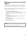
This shop manual has been prepared as an aid to improve the quality of repairs by giving the serviceman an
accurate understanding of the product and by showing him the correct way to perform repairs and make judgements. Make sure you understand the contents of this manual and use it to full effect at every opportunity.
This shop manual mainly contains the necessary technical information for operations performed in a service
workshop. For ease of understanding, the manual is divided into the following chapters; these chapters are further divided into the each main group of components.
STRUCTURE, FUNCTION AND MAINTENANCE STANDARD
This section explains the structure and function of each component. It serves not only to give an understanding of the structure, but also serves as reference material for troubleshooting.
In addition, this section may contain hydraulic circuit diagrams, electric circuit diagrams, and maintenance standards.
TESTING AND ADJUSTING
This section explains checks to be made before and after performing repairs, as well as adjustments to
be made at completion of the checks and repairs.
Troubleshooting charts correlating "Problems" with "Causes" are also included in this section.
DISASSEMBLY AND ASSEMBLY
This section explains the procedures for removing, installing, disassembling and assembling each component, as well as precautions for them.
PERAIR AND REPLACEMENT OF PARTS
NOTICE
The specifications contained in this shop manual are subject to change at any time and without any
advance notice. Use the specifications given in the book with the latest date.
00-5
FOREWORD
HOW TO READ THE SHOP MANUAL
HOW TO READ THE SHOP MANUAL
DISTRIBUTION AND UPDATING
Any additions, amendments or other changes will be
sent to KOMATSU distributors. Get the most up-todate information before you start any work.
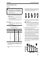
SYMBOLS
So that the shop manual can be of ample practical
use, important safety and quality portions are
marked with the following symbols.
Symbol
Item
Remarks
k
Safety
Special safety precautions
are necessary when performing the work.
Caution
Special technical precautions or other precautions
for preserving standards
are necessary when performing the work.
4
Weight
Weight of parts of systems. Caution necessary
when selecting hoisting
wire, or when working posture is important, etc.
3
Tightening
torque
Places that require special
attention for the tightening
torque during assembly.
2
Coat
Places to be coated with
adhesives and lubricants,
etc.
5
Oil, water
Places where oil, water or
fuel must be added, and
the capacity.
6
Drain
Places where oil or water
must be drained, and
quantity to be drained.
a
00-6
FOREWORD
HOISTING INSTRUCTIONS
HOISTING INSTRUCTIONS
HOISTING
k Heavy parts (25 kg or more) must be lifted
with a hoist, etc. In the DISASSEMBLY
AND ASSEMBLY section, every part
weighing 25 kg or more is indicated clearly
with the symbol 4
•
If a part cannot be smoothly removed from the
machine by hoisting, the following checks
should be made:
1) Check for removal of all bolts fastening the
part to the relative parts.
2) Check for existence of another part causing
interference with the part to be removed.
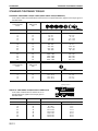
WIRE ROPES
1) Use adequate ropes depending on the
weight of parts to be hoisted, referring to
the table below:
Wire ropes
(Standard "Z" or "S" twist ropes
without galvanizing)
Rope diameter
Allowable load
mm
kN
tons
10
11.5
12.5
14
16
18
20
22.4
30
40
50
60
9.8
13.7
15.7
21.6
27.5
35.3
43.1
54.9
98.1
176.5
274.6
392.2
1.0
1.4
1.6
2.2
2.8
3.6
4.4
5.6
10.0
18.0
28.0
40.0
Slinging near the edge of the hook may cause
the rope to slip off the hook during hoisting, and
a serious accident can result. Hooks have maximum strength at the middle portion.
100%
88%
79%
71%
41%
SAD00479
3) Do not sling a heavy load with one rope alone,
but sling with two or more ropes symmetrically
wound onto the load.
k Slinging with one rope may cause turning
of the load during hoisting, untwisting of
the rope, or slipping of the rope from its
original winding position on the load, which
can result in a dangerous accident.
4) Do not sling a heavy load with ropes forming a
wide hanging angle from the hook.
When hoisting a load with two or more ropes,
the force subjected to each rope will increase
with the hanging angles. The table below
shows the variation of allowable load kN {kg}
when hoisting is made with two ropes, each of
which is allowed to sling up to 9.8 kN {1000 kg}
vertically, at various hanging angles.
When two ropes sling a load vertically, up to
19.6 kN {2000 kg} of total weight can be suspended. This weight becomes 9.8 kN {1000 kg}
when two ropes make a 120° hanging angle.
On the other hand, two ropes are subjected to
an excessive force as large as 39.2 kN {4000
kg} if they sling a 19.6 kN {2000 kg} load at a
lifting angle of 150°.
★ The allowable load value is estimated to be onesixth or one-seventh of the breaking strength of
the rope used.
2) Sling wire ropes from the middle portion of the
hook.
00-7
FOREWORD
METHOD OF DISASSEMBLING, CONNECTING PUSH-PULL TYPE COUPLER
METHOD OF DISASSEMBLING, CONNECTING PUSH-PULL TYPE COUPLER
k Before carrying out the following work, release
the residual pressure from the hydraulic tank.
For details, see TESTING AND ADJUSTING,
Releasing residual pressure from hydraulic
tank.
k Even if the residual pressure is released from
the hydraulic tank, some hydraulic oil flows out
when the hose is disconnected. Accordingly,
prepare an oil receiving container.
Disconnection
1) Release the residual pressure from the hydraulic tank. For details, see TESTING AND
ADJUSTING, Releasing residual pressure from
hydraulic tank.
2) Hold adapter (1) and push hose joint (2) into
mating adapter (3). (See Fig. 1)
The adapter can be pushed in about 3.5
mm.
Do not hold rubber cap portion (4).
3) After hose joint (2) is pushed into adapter (3),
press rubber cap portion (4) against (3) until it
clicks. (See Fig. 2)
4) Hold hose adapter (1) or hose (5) and pull it out.
(See Fig. 3)
Since some hydraulic oil flows out, prepare
an oil receiving container.
Connection
1) Hold hose adapter (1) or hose (5) and insert it in
mating adapter (3), aligning them with each
other. (See Fig. 4)
Do not hold rubber cap portion (4).
2) After inserting the hose in the mating adapter
perfectly, pull it back to check its connecting
condition. (See Fig. 5)
When the hose is pulled back, the rubber
cap portion moves toward the hose about
3.5 mm. This does not indicate abnormality,
however.
00-8
Type 1
FOREWORD
METHOD OF DISASSEMBLING, CONNECTING PUSH-PULL TYPE COUPLER
Type 3
1) Hold the mouthpiece of the tightening portion
and push body (2) in straight until sliding prevention ring (1) contacts contact surface a of
the hexagonal portion at the male end.
1) Hold the mouthpiece of the tightening portion
and push body (2) in straight until sliding prevention ring (1) contacts contact surface a of
the hexagonal portion at the male end.
2) Hold in the condition in Step 1), and turn
lever (4) to the right (clockwise).
2) Hold in the condition in Step 1), and push
until cover (3) contacts contact surface a of
the hexagonal portion at the male end.
3) Hold in the condition in Steps 1) and 2), and
pull out whole body (2) to disconnect it.
3) Hold in the condition in Steps 1) and 2), and
pull out whole body (2) to disconnect it.
•
•
Disassembly
Type 2
Hold the mouthpiece of the tightening portion
and push body (2) in straight until sliding prevention ring (1) contacts contact surface a of
the hexagonal portion at the male end to connect it.
Connection
Hold the mouthpiece of the tightening portion
and push body (2) in straight until sliding prevention ring (1) contacts contact surface a of
the hexagonal portion at the male end to connect it.
00-9
FOREWORD
COATING MATERIALS
COATING MATERIALS
The recommended coating materials such as adhesives, gasket sealants and greases used for disassembly
and assembly are listed below.
For coating materials not listed below, use the equivalent of products shown in this list.
Category
Komatsu code
Part No.
LT-1A
790-129-9030
LT-1B
790-129-9050
LT-2
09940-00030
LT-3
790-129-9060
(Set of adhesive
and hardening
agent)
LT-4
790-129-9040
Holtz
MH 705
790-126-9120
Three bond
1735
790-129-9140
Aron-alpha
201
790-129-9130
Loctite
648-50
79A-129-9110
LG-1
790-129-9010
LG-5
790-129-9080
LG-6
790-129-9020
LG-7
790-129-9070
Three bond
1211
790-129-9090
Three bond
1207B
419-15-18131
Adhesives
Gasket
sealant
00-10
Q’ty
Container
Main applications, features
• Used to prevent rubber gaskets, rubber
cushions, and cock plug from coming out.
• Used in places requiring an immediately
effective, strong adhesive.
Used for plastics (except polyethylene,
20 g
Polyethylene
polyprophylene, tetrafluoroethlene and
(2 pcs.)
container
vinyl chloride), rubber, metal and nonmetal.
• Features:
Polyethylene
Resistance to heat and chemicals
50 g
container
• Used for anti-loosening and sealant
purpose for bolts and plugs.
Adhesive:
• Used as adhesive or sealant for metal,
1 kg
glass and plastic.
Hardening
Can
agent:
500 g
Polyethylene • Used as sealant for machined holes.
250 g
container
• Used as heat-resisting sealant for
75 g
Tube
repairing engine.
• Quick hardening type adhesive
Polyethylene • Cure time: within 5 sec. to 3 min.
50 g
container
• Used mainly for adhesion of metals,
rubbers, plastics and woods.
• Quick hardening type adhesive
• Quick cure type
Polyethylene
(max. strength after 30 minutes)
2g
container
• Used mainly for adhesion of rubbers,
plastics and metals.
• Resistance to heat, chemicals
Polyethylene
• Used at joint portions subject to high
50 cc
container
temperatures.
• Used as adhesive or sealant for gaskets
200 g
Tube
and packing of power train case, etc.
• Used as sealant for various threads, pipe
joints, flanges.
1 kg
Can
• Used as sealant for tapered plugs,
elbows, nipples of hydraulic piping.
• Features: Silicon based, resistance to
heat, cold
200 g
Tube
• Used as sealant for flange surface, tread.
• Used as sealant for oil pan, final drive
case, etc.
• Features: Silicon based, quick hardening
type
• Used as sealant for flywheel housing,
1 kg
Tube
intake manifold, oil pan, thermostat
housing, etc.
• Used as heat-resisting sealant for
100 g
Tube
repairing engine.
• Features: Silicone type, heat resistant,
vibration resistant, and impact resistant
100 g
Tube
sealing material
• Used as sealing material for transfer case
150 g
Tube
FOREWORD
Molybdenum
disulphide
lubricant
Komatsu code
Part No.
Q’ty
Container
LM-G
09940-00051
60 g
Can
LM-P
09940-00040
200 g
Tube
Various
Various
G2-LI
G2-CA
Grease
Primer
Adhesive
Caulking
material
SYG2-400LI
SYG2-350LI
SYG2-400LI-A
SYG2-160LI
SYGA-160CNLI
SYG2-400CA
SYG2-350CA
SYG2-400CA-A
SYG2-160CA
SYGA-160CNCA
Various
Various
Molybdenum
disulphide
grease
LM-G (G2-M)
Hyper White
Grease G2-T
G0-T (*)
*: For use in
cold district
Biogrease G2B
G2-BT (*)
*: For high
temperature
and large load
SUNSTAR
PAINT PRIMER
580 SUPER
SUNSTAR
GLASS PRIMER
580 SUPER
SUNSTAR
PAINT PRIMER
435-95
SYG2-400T-A
SYG2-16CNT
SYG0-400T-A (*)
SYG0-16CNT (*)
400 g
16 kg
SYG2-400B
SYGA-16CNB
SYG2-400BT (*)
SYGA-16CNBT (*)
400 g
16 kg
Bellows type
Can
20 ml
Glass
container
20 ml
Glass
container
22M-54-27230
20 ml
Glass
container
SUNSTAR
GLASS PRIMER
435-41
22M-54-27240
150 ml
Can
22M-54-27250
20 ml
Glass
container
22M-54-27210
320 ml
Ecocart
(Special
container)
417-926-3910
320 ml
Polyethylene
container
20Y-54-39850
310 ml
Polyethylene
container
417-926-3920
320 ml
Polyethylene
container
20Y-54-55130
333 ml
Polyethylene
container
22M-54-27220
333 ml
Cartridge
SUNSTAR
SASH PRIMER
GP-402
SUNSTAR
PENGUINE
SUPER 560
SUNSTAR
PENGUINE
SEAL 580
SUPER “S” or
“W”
Sika Japan,
Sikaflex 256HV
SUNSTAR
PENGUINE
SEAL No. 2505
SEKISUI
SILICONE
SEALANT
GE TOSHIBA
SILICONES
TOSSEAL 381
SYG2-400M
SYG2-400M-A
SYGA-16CNM
400 g × 10 Bellows type
400 g × 20 Bellows type
16 kg
Can
Main applications, features
• Used as lubricant for sliding portion (to
prevent from squeaking).
• Used to prevent seizure or scuffling of the
thread when press fitting or shrink fitting.
• Used as lubricant for linkage, bearings,
etc.
• General purpose type
• Used for normal temperature, light load
bearing at places in contact with water or
steam.
• Used for heavy load portion
• Seizure resistance and heat resistance
higher than molybdenum disulfide grease
Bellows type
• Since this grease is white, it does not
Can
stand out against machine body.
• Since this grease is decomposed by
bacteria in short period, it has less effects
on microorganisms, animals, and plants.
• Used as primer for cab side
(Using limit: 4 months)
417-926-3910
• Used as primer for glass side
(Using limit: 4 months)
Adhesive for cab glass
Category
COATING MATERIALS
• Used as primer for painted surface on
cab side
(Using limit: 4 months)
• Used as primer for black ceramiccoated surface on glass side and for
hard polycarbonate-coated surface
(Using limit: 4 months)
• Used as primer for sash (Alumite).
(Using limit: 4 months)
• Used as adhesive for glass.
(Using limit: 6 months)
• “S” is used for high-temperature
season (April - October) and “W” for
low-temperature season (November April) as adhesive for glass.
(Using limit: 4 months)
• Used as adhesive for glass.
(Using limit: 6 months)
• Used to seal joints of glass parts.
(Using limit: 4 months)
• Used to seal front window.
(Using limit: 6 months)
• Used to seal joint of glasses.
Translucent white seal.
(Using limit: 12 months)
00-11
FOREWORD
STANDARD TIGHTENING TORQUE
STANDARD TIGHTENING TORQUE
STANDARD TIGHTENING TORQUE TABLE (WHEN USING TORQUE WRENCH)
In the case of metric nuts and bolts for which there is no special instruction, tighten to the torque given in
the table below.
Tightening torque
Thread diameter
of bolt
Width across
flats
mm
mm
Nm
kgm
6
8
10
12
14
10
13
17
19
22
11.8 – 14.7
27 – 34
59 – 74
98 – 123
153 – 190
1.2 – 1.5
2.8 – 3.5
6 – 7.5
10 – 12.5
15.5 – 19.5
16
18
20
22
24
24
27
30
32
36
235 – 285
320 – 400
455 – 565
610 – 765
785 – 980
23.5 – 29.5
33 – 41
46.5 – 58
62.5 – 78
80 – 100
27
30
33
36
39
41
46
50
55
60
1150 – 1440
1520 – 1910
1960 – 2450
2450 – 3040
2890 – 3630
118 – 147
155 – 195
200 – 250
250 – 310
295 – 370
Thread diameter
of bolt
Width across
flats
mm
mm
Nm
kgm
6
8
10
12
10
12
14
17
5.9 – 9.8
13.7 – 23.5
34.3 – 46.1
74.5 – 90.2
0.6 – 1.0
1.4 – 2.4
3.5 – 4.7
7.6 – 9.2
Tightening torque
Sealing surface
TABLE OF TIGHTENING TORQUES FOR FLARED NUTS
In the case of flared nuts for which there is no
special instruction, tighten to the torque given in
the table below.
SAD00483
Thread diameter
Width across flat
mm
mm
Nm
kgm
14
18
22
24
30
33
36
42
19
24
27
32
36
41
46
55
24.5 ± 4.9
49 ± 19.6
78.5 ± 19.6
137.3 ± 29.4
176.5 ± 29.4
196.1 ± 49
245.2 ± 49
294.2 ± 49
2.5 ± 0.5
5±2
8±2
14 ± 3
18 ± 3
20 ± 5
25 ± 5
30 ± 5
00-12
Tightening torque
FOREWORD
STANDARD TIGHTENING TORQUE
TABLE OF TIGHTENING TORQUES FOR SPLIT FLANGE BOLTS
In the case of split flange bolts for which there is no special instruction, tighten to the torque given in the
table below.
Thread diameter
Width across flat
Tightening torque
mm
mm
Nm
kgm
10
12
16
14
17
22
59 – 74
98 – 123
235 – 285
6 – 7.5
10 – 12.5
23.5 – 29.5
TABLE OF TIGHTENING TORQUES FOR O-RING BOSS PIPING JOINTS
Unless there are special instructions, tighten the O-ring boss piping joints to the torque below.
Thread diameter
Width across flat
mm
mm
14
20
24
33
42
Varies depending
on type of
connector.
Tightening torque (Nm {kgm})
Norminal No.
02
03, 04
05, 06
10, 12
14
Range
35 – 63
84 – 132
128 – 186
363 – 480
746 – 1010
{3.5 – 6.5}
{8.5 – 13.5}
{13.0 – 19.0}
{37.0 – 49.0}
{76.0 – 103}
Target
44 {4.5}
103 {10.5}
157 {16.0}
422 {43.0}
883 {90.0}
TABLE OF TIGHTENING TORQUES FOR O-RING BOSS PLUGS
Unless there are special instructions, tighten the O-ring boss plugs to the torque below.
Thread diameter
Width across flat
Tightening torque (Nm {kgm})
mm
mm
Range
Target
08
10
12
14
16
18
20
24
30
33
36
42
52
14
17
19
22
24
27
30
32
32
—
36
—
—
5.88 – 8.82 {0.6 – 0.9}
9.8 – 12.74 {1.0 – 1.3}
14.7 – 19.6 {1.5 – 2.0}
19.6 – 24.5 {2.0 – 2.5}
24.5 – 34.3 {2.5 – 3.5}
34.3 – 44.1 {3.5 – 4.5}
44.1 – 53.9 {4.5 – 5.5}
58.8 – 78.4 {6.0 – 8.0}
93.1 – 122.5 {9.5 – 12.5}
107.8 – 147.0 {11.0 – 15.0}
127.4 – 176.4 {13.0 – 18.0}
181.3 – 240.1 {18.5 – 24.5}
274.4 – 367.5 {28.0 – 37.5}
7.35 {0.75}
11.27 {1.15}
17.64 {1.8}
22.54 {2.3}
29.4 {3.0}
39.2 {4.0}
49.0 {5.0}
68.6 {7.0}
107.8 {11.0}
124.4 {13.0}
151.9 {15.5}
210.7 {21.5}
323.4 {33.0}
Norminal No.
08
10
12
14
16
18
20
24
30
33
36
42
52
00-13
FOREWORD
STANDARD TIGHTENING TORQUE
TIGHTENING TORQUE FOR 102 AND 114 ENGINE SERIES
1) BOLT AND NUTS
Use these torques for bolts and nuts (unit: mm) of Cummins Engine.
Thread diameter
Tightening torque
mm
Nm
kgm
6
8
10
12
10 0 2
24 0 4
43 0 6
77 0 12
1.02 0 0.20
2.45 0 0.41
4.38 0 0.61
7.85 0 1.22
2) EYE JOINTS
Use these torques for eye joints (unit: mm) of Cummins Engine.
Thread diameter
Tightening torque
mm
Nm
kgm
6
8
10
12
14
802
10 0 2
12 0 2
24 0 4
36 0 5
0.81 0 0.20
1.02 0 0.20
1.22 0 0.20
2.45 0 0.41
3.67 0 0.51
3) TAPERED SCREWS
Use these torques for tapered screws (unit: inch) of Cummins Engine.
Tightening torque
Material
In Cast Iron or Steel
In Aluminum
Thread size (inch)
Nm
kgm
Nm
kgm
1 / 16
1/8
1/4
3/8
1/2
3/4
15 0 2
20 0 2
25 0 3
35 0 4
55 0 6
75 0 8
1.53 0 0.20
2.04 0 0.20
2.55 0 0.31
3.57 0 0.41
5.61 0 0.61
7.65 0 0.82
501
15 0 2
20 0 2
25 0 3
35 0 4
45 0 5
0.51 0 0.10
1.53 0 0.20
2.04 0 0.20
2.55 0 0.31
3.57 0 0.41
4.59 0 0.51
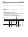
TIGHTENING TORQUE TABLE FOR HOSES (TAPER SEAL TYPE AND FACE SEAL TYPE)
★ Tighten the hoses (taper seal type and face seal type) to the following torque, unless otherwise specified.
★ Apply the following torque when the threads are coated (wet) with engine oil.
Tightening torque (Nm {kgm})
Nominal size Width across
of hose
flats
Taper seal
type
Face seal type
Thread size Nominal thread
Root diameter
size - Threads per (mm) (Reference)
(mm)
inch, Thread series
Range
Target
34 – 54 {3.5 – 5.5}
44 {4.5}
–
9
— – 18UN
16
14.3
34 – 63 {3.5 – 6.5}
44 {4.5}
14
–
–
22
54 – 93 {5.5 – 9.5}
74 {7.5}
–
11
— – 16UN
16
17.5
24
59 – 98 {6.0 – 10.0}
78 {8.0}
18
–
–
04
27
84 – 132 {8.5 – 13.5}
103 {10.5}
22
13
— – 16UN
16
20.6
05
32
128 – 186 {13.0 – 19.0}
157 {16.0}
24
1 – 14UNS
25.4
06
36
177 – 245 {18.0 – 25.0}
216 {22.0}
30
3
1 — – 12UN
16
30.2
02
03
19
(10)
41
177 – 245 {18.0 – 25.0}
216 {22.0}
33
–
–
(12)
46
197 – 294 {20.0 – 30.0}
245 {25.0}
36
–
–
(14)
55
246 – 343 {25.0 – 35.0}
294 {30.0}
42
–
–
00-14
FOREWORD
ELECTRIC WIRE CODE
ELECTRIC WIRE CODE
In the wiring diagrams, various colors and symbols are employed to indicate the thickness of wires.
This wire code table will help you understand WIRING DIAGRAMS.
Example: 5WB indicates a cable having a nominal number 5 and white coating with black stripe.
CLASSIFICATION BY THICKNESS
Copper wire
Cable O.D.
(mm)
Current
rating
(A)
Applicable circuit
0.88
2.4
12
Starting, lighting, signal
etc.
0.32
2.09
3.1
20
Lighting, signal etc.
65
0.32
5.23
4.6
37
Charging and signal
15
84
0.45
13.36
7.0
59
Starting (Glow plug)
40
85
0.80
42.73
11.4
135
Starting
60
127
0.80
63.84
13.6
178
Starting
100
217
0.80
109.1
17.6
230
Starting
Norminal
number
Number of
strands
Dia. of
strands
(mm2)
Cross
section
(mm2)
0.85
11
0.32
2
26
5
CLASSIFICATION BY COLOR AND CODE
Circuits
Priority
Classification
1
Primary
Charging
Ground
Starting
Lighting
Instrument
Signal
Other
Code
W
B
B
R
Y
G
L
Color
White
Black
Black
Red
Yellow
Green
Blue
Code
WR
—
BW
RW
YR
GW
LW
2
Color White & Red
—
Code
—
WB
White & Black Red & White Rellow & Red Green & White Blue & White
BY
RB
YB
GR
LR
3
4
Auxiliary
Color White & Black
—
Code
—
WL
Black & Yellow Red & Black Yellow & Black Green & Red Blue & Yellow
BR
Color White & Blue
—
Code
—
—
Color White & Green
—
—
Code
—
—
—
Color
—
—
—
WG
RY
Black & Red Red & Yellow
RG
YG
GY
LY
Yellow &
Green
Green &
Yellow
Blue & Yellow
YL
GB
LB
5
Red & Green Yellow & Blue Green & Black Blue & Black
RL
YW
GL
n
6
Red & Blue Yellow & White Green & Blue
n
00-15
FOREWORD
CONVERSION TABLE
CONVERSION TABLE
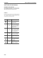
METHOD OF USING THE CONVERSION TABLE
The Conversion Table in this section is provided to enable simple conversion of figures. For details of the
method of using the Conversion Table, see the example given below.
EXAMPLE
• Method of using the Conversion Table to convert from millimeters to inches
1. Convert 55 mm into inches.
(1) Locate the number 50 in the vertical column at the left side, take this as (A), then draw a horizontal line
from (A).
(2) Locate the number 5 in the row across the top, take this as (B), then draw a perpendicular line down
from (B).
(3) Take the point where the two lines cross as (C). This point (C) gives the value when converting from
millimeters to inches. Therefore, 55 mm = 2.165 inches.
2. Convert 550 mm into inches.
(1) The number 550 does not appear in the table, so divide by 10 (move the decimal point one place to the
left) to convert it to 55 mm.
(2) Carry out the same procedure as above to convert 55 mm to 2.165 inches.
(3) The original value (550 mm) was divided by 10, so multiply 2.165 inches by 10 (move the decimal point
one place to the right) to return to the original value. This gives 550 mm = 21.65 inches.
(B)
Millimeters to inches
1 mm = 0.03937 in
(A)
00-16
0
1
2
3
4
0
10
20
30
40
0
0.394
0.787
1.181
1.575
0.039
0.433
0.827
1.220
1.614
0.079
0.472
0.866
1.260
1.654
0.118
0.512
0.906
1.299
1.693
0.157
0.551
0.945
1.339
1.732
50
60
70
80
90
1.969
2.362
2.756
3.150
3.543
2.008
2.402
2.795
3.189
3.583
2.047
2.441
2.835
3.228
3.622
2.087
2.480
2.874
3.268
3.661
2.126
2.520
2.913
3.307
3.701
5
0.197
0.591
0.984
1.378
1.772
(C)
2.165
2.559
2.953
3.346
3.740
6
7
8
9
0.236
0.630
1.024
1.417
1.811
0.276
0.669
1.063
1.457
1.850
0.315
0.709
1.102
1.496
1.890
0.354
0.748
1.142
1.536
1.929
2.205
2.598
2.992
3.386
3.780
2.244
2.638
3.032
3.425
3.819
2.283
2.677
3.071
3.465
3.858
2.323
2.717
3.110
3.504
3.898
FOREWORD
CONVERSION TABLE
Millimeters to Inches
1 mm = 0.03937 in
0
1
2
3
4
5
6
7
8
9
0
0.039
0.079
0.118
0.157
0.197
0.236
0.276
0.315
0.354
10
0.394
0.433
0.472
0.512
0.551
0.591
0.630
0.669
0.709
0.748
20
0.787
0.827
0.866
0.906
0.945
0.984
1.024
1.063
1.102
1.142
30
1.181
1.220
1.260
1.299
1.339
1.378
1.417
1.457
1.496
1.536
40
1.575
1.614
1.654
1.693
1.732
1.772
1.811
1.850
1.890
1.929
50
1.969
2.008
2.047
2.087
2.126
2.165
2.205
2.244
2.283
2.323
60
2.362
2.402
2.441
2.480
2.520
2.559
2.598
2.638
2.677
2.717
70
2.756
2.795
2.835
2.874
2.913
2.953
2.992
3.032
3.071
3.110
80
3.150
3.189
3.228
3.268
3.307
3.346
3.386
3.425
3.465
3.504
90
3.543
3.583
3.622
3.661
3.701
3.740
3.780
3.819
3.858
3.898
0
Kilogram to Pound
1 kg = 2.2046 lb
0
0
0
1
2
3
4
5
6
7
8
9
2.20
4.41
6.61
8.82
11.02
13.23
15.43
17.64
19.84
10
22.05
24.25
26.46
28.66
30.86
33.07
35.27
37.48
39.68
41.89
20
44.09
46.30
48.50
50.71
51.91
55.12
57.32
59.53
61.73
63.93
30
66.14
68.34
70.55
72.75
74.96
77.16
79.37
81.57
83.78
85.98
40
88.18
90.39
92.59
94.80
97.00
99.21
101.41
103.62
105.82
108.03
50
110.23
112.44
114.64
116.85
119.05
121.25
123.46
125.66
127.87
130.07
60
132.28
134.48
136.69
138.89
141.10
143.30
145.51
147.71
149.91
152.12
70
154.32
156.53
158.73
160.94
163.14
165.35
167.55
169.76
171.96
174.17
80
176.37
178.57
180.78
182.98
185.19
187.39
189.60
191.80
194.01
196.21
90
198.42
200.62
202.83
205.03
207.24
209.44
211.64
213.85
216.05
218.26
00-17
FOREWORD
CONVERSION TABLE
Liter to U.S. Gallon
1l = 0.2642 U.S. Gal
0
1
2
3
4
5
6
7
8
9
0
0.264
0.528
0.793
1.057
1.321
1.585
1.849
2.113
2.378
10
2.642
2.906
3.170
3.434
3.698
3.963
4.227
4.491
4.755
5.019
20
5.283
5.548
5.812
6.076
6.340
6.604
6.869
7.133
7.397
7.661
30
7.925
8.189
8.454
8.718
8.982
9.246
9.510
9.774
10.039
10.303
40
10.567
10.831
11.095
11.359
11.624
11.888
12.152
12.416
12.680
12.944
50
13.209
13.473
13.737
14.001
14.265
14.529
14.795
15.058
15.322
15.586
60
15.850
16.115
16.379
16.643
16.907
17.171
17.435
17.700
17.964
18.228
70
18.492
18.756
19.020
19.285
19.549
19.813
20.077
20.341
20.605
20.870
80
21.134
21.398
21.662
21.926
22.190
22.455
22.719
22.983
23.247
23.511
90
23.775
24.040
24.304
24.568
24.832
25.096
25.361
25.625
25.889
26.153
0
Liter to U.K. Gallon
1l = 0.21997 U.K. Gal
0
1
2
3
4
5
6
7
8
9
0
0.220
0.440
0.660
0.880
1.100
1.320
1.540
1.760
1.980
10
2.200
2.420
2.640
2.860
3.080
3.300
3.520
3.740
3.950
4.179
20
4.399
4.619
4.839
5.059
5.279
5.499
5.719
5.939
6.159
6.379
30
6.599
6.819
7.039
7.259
7.479
7.969
7.919
8.139
8.359
8.579
40
8.799
9.019
9.239
9.459
9.679
9.899
10.119
10.339
10.559
10.778
50
10.998
11.281
11.438
11.658
11.878
12.098
12.318
12.528
12.758
12.978
60
13.198
13.418
13.638
13.858
14.078
14.298
14.518
14.738
14.958
15.178
70
15.398
15.618
15.838
16.058
16.278
16.498
16.718
16.938
17.158
17.378
80
17.598
17.818
18.037
18.257
18.477
18.697
18.917
19.137
19.357
19.577
90
19.797
20.017
20.237
20.457
20.677
20.897
21.117
21.337
21.557
21.777
0
00-18
FOREWORD
CONVERSION TABLE
kgm to ft. lb
1 kgm = 7.233 ft. lb
0
1
2
3
4
5
6
7
8
9
0
0
7.2
14.5
21.7
28.9
36.2
43.4
50.6
57.9
65.1
10
72.3
79.6
86.8
94.0
101.3
108.5
115.7
123.0
130.2
137.4
20
144.7
151.9
159.1
166.4
173.6
180.8
188.1
195.3
202.5
209.8
30
217.0
224.2
231.5
238.7
245.9
253.2
260.4
267.6
274.9
282.1
40
289.3
296.6
303.8
311.0
318.3
325.5
332.7
340.0
347.2
354.4
50
361.7
368.9
376.1
383.4
390.6
397.8
405.1
412.3
419.5
426.8
60
434.0
441.2
448.5
455.7
462.9
470.2
477.4
484.6
491.8
499.1
70
506.3
513.5
520.8
528.0
535.2
542.5
549.7
556.9
564.2
571.4
80
578.6
585.9
593.1
600.3
607.6
614.8
622.0
629.3
636.5
643.7
90
651.0
658.2
665.4
672.7
679.9
687.1
694.4
701.6
708.8
716.1
100
723.3
730.5
737.8
745.0
752.2
759.5
766.7
773.9
781.2
788.4
110
795.6
802.9
810.1
817.3
824.6
831.8
839.0
846.3
853.5
860.7
120
868.0
875.2
882.4
889.7
896.9
904.1
911.4
918.6
925.8
933.1
130
940.3
947.5
954.8
962.0
969.2
976.5
983.7
990.9
998.2
1005.4
140
1012.6
1019.9
1027.1
1034.3
1041.5
1048.8
1056.0
1063.2
1070.5
1077.7
150
1084.9
1092.2
1099.4
1106.6
1113.9
1121.1
1128.3
1135.6
1142.8
1150.0
160
1157.3
1164.5
1171.7
1179.0
1186.2
1193.4
1200.7
1207.9
1215.1
1222.4
170
1129.6
1236.8
1244.1
1251.3
1258.5
1265.8
1273.0
1280.1
1287.5
1294.7
180
1301.9
1309.2
1316.4
1323.6
1330.9
1338.1
1345.3
1352.6
1359.8
1367.0
190
1374.3
1381.5
1388.7
1396.0
1403.2
1410.4
1417.7
1424.9
1432.1
1439.4
00-19
FOREWORD
CONVERSION TABLE
kg/cm2 to lb/in2
1kg/cm2 = 14.2233 lb/in2
0
1
2
3
4
5
6
7
8
9
0
0
14.2
28.4
42.7
56.9
71.1
85.3
99.6
113.8
128.0
10
142.2
156.5
170.7
184.9
199.1
213.4
227.6
241.8
256.0
270.2
20
284.5
298.7
312.9
327.1
341.4
355.6
369.8
384.0
398.3
412.5
30
426.7
440.9
455.1
469.4
483.6
497.8
512.0
526.3
540.5
554.7
40
568.9
583.2
597.4
611.6
625.8
640.1
654.3
668.5
682.7
696.9
50
711.2
725.4
739.6
753.8
768.1
782.3
796.5
810.7
825.0
839.2
60
853.4
867.6
881.8
896.1
910.3
924.5
938.7
953.0
967.2
981.4
70
995.6
1010
1024
1038
1053
1067
1081
1095
1109
1124
80
1138
1152
1166
1181
1195
1209
1223
1237
1252
1266
90
1280
1294
1309
1323
1337
1351
1365
1380
1394
1408
100
1422
1437
1451
1465
1479
1493
1508
1522
1536
1550
110
1565
1579
1593
1607
1621
1636
1650
1664
1678
1693
120
1707
1721
1735
1749
1764
1778
1792
1806
1821
1835
130
1849
1863
1877
1892
1906
1920
1934
1949
1963
1977
140
1991
2005
2020
2034
2048
2062
2077
2091
2105
2119
150
2134
2148
2162
2176
2190
2205
2219
2233
2247
2262
160
2276
2290
2304
2318
2333
2347
2361
2375
2389
2404
170
2418
2432
2446
2460
2475
2489
2503
2518
2532
2546
180
2560
2574
2589
2603
2617
2631
2646
2660
2674
2688
190
2702
2717
2731
2745
2759
2773
2788
2802
2816
2830
200
2845
2859
2873
2887
2901
2916
2930
2944
2958
2973
210
2987
3001
3015
3030
3044
3058
3072
3086
3101
3115
220
3129
3143
3158
3172
3186
3200
3214
3229
3243
3257
230
3271
3286
3300
3314
3328
3343
3357
3371
3385
3399
240
3414
3428
3442
3456
3470
3485
3499
3513
3527
3542
00-20
FOREWORD
CONVERSION TABLE
Temperature
Fahrenheit-Centigrade Conversion ; a simple way to convert a Fahrenheit temperature reading into a Centigrade temperature reading or vice versa is to enter the accompanying table in the center or boldface column of figures.
These figures refer to the temperature in either Fahrenheit or Centigrade degrees.
If it is desired to convert from Fahrenheit to Centigrade degrees, consider the center column as a table of
Fahrenheit temperatures and read the corresponding Centigrade temperature in the column at the left.
If it is desired to convert from Centigrade to Fahrenheit degrees, consider the center column as a table of
Centigrade values, and read the corresponding Fahrenheit temperature on the right.
1°C = 33.8°F
°C
°F
°C
°F
°C
°F
°C
°F
–40.4
–37.2
–34.4
–31.7
–28.9
–40
–35
–30
–25
–20
–40.0
–31.0
–22.0
–13.0
–4.0
–11.7
–11.1
–10.6
–10.0
–9.4
11
12
13
14
15
51.8
53.6
55.4
57.2
59.0
7.8
8.3
8.9
9.4
10.0
46
47
48
49
50
114.8
116.6
118.4
120.2
122.0
27.2
27.8
28.3
28.9
29.4
81
82
83
84
85
117.8
179.6
181.4
183.2
185.0
–28.3
–27.8
–27.2
–26.7
–26.1
–19
–18
–17
–16
–15
–2.2
–0.4
1.4
3.2
5.0
–8.9
–8.3
–7.8
–7.2
–6.7
16
17
18
19
20
60.8
62.6
64.4
66.2
68.0
10.6
11.1
11.7
12.2
12.8
51
52
53
54
55
123.8
125.6
127.4
129.2
131.0
30.0
30.6
31.1
31.7
32.2
86
87
88
89
90
186.8
188.6
190.4
192.2
194.0
–25.6
–25.0
–24.4
–23.9
–23.3
–14
–13
–12
–11
–10
6.8
8.6
10.4
12.2
14.0
–6.1
–5.6
–5.0
–4.4
–3.9
21
22
23
24
25
69.8
71.6
73.4
75.2
77.0
13.3
13.9
14.4
15.0
15.6
56
57
58
59
0
132.8
134.6
136.4
138.2
140.0
32.8
33.3
33.9
34.4
35.0
91
92
93
94
95
195.8
197.6
199.4
201.2
203.0
–22.8
–22.2
–21.7
–21.1
–20.6
–9
–8
–7
–6
–5
15.8
17.6
19.4
21.2
23.0
–3.3
–2.8
–2.2
–1.7
–1.1
26
27
28
29
30
78.8
80.6
82.4
84.2
86.0
16.1
16.7
17.2
17.8
18.3
61
62
63
64
65
141.8
143.6
145.4
147.2
149.0
35.6
36.1
36.7
37.2
37.8
96
97
98
99
100
204.8
206.6
208.4
210.2
212.0
–20.0
–19.4
–18.9
–18.3
–17.8
–4
–3
–2
–1
0
24.8
26.6
28.4
30.2
32.0
–0.6
0
0.6
1.1
1.7
31
32
33
34
35
87.8
89.6
91.4
93.2
95.0
18.9
19.4
20.0
20.6
21.1
66
67
68
69
70
150.8
152.6
154.4
156.2
158.0
40.6
43.3
46.1
48.9
51.7
105
110
115
120
125
221.0
230.0
239.0
248.0
257.0
–17.2
–16.7
–16.1
–15.6
–15.0
1
2
3
4
5
33.8
35.6
37.4
39.2
41.0
2.2
2.8
3.3
3.9
4.4
36
37
38
39
40
96.8
98.6
100.4
102.2
104.0
21.7
22.2
22.8
23.3
23.9
71
72
73
74
75
159.8
161.6
163.4
165.2
167.0
54.4
57.2
60.0
62.7
65.6
130
135
140
145
150
266.0
275.0
284.0
293.0
302.0
–14.4
–13.9
–13.3
–12.8
–12.2
6
7
8
9
10
42.8
44.6
46.4
48.2
50.0
5.0
5.6
6.1
6.7
7.2
41
42
43
44
45
105.8
107.6
109.4
111.2
113.0
24.4
25.0
25.6
26.1
26.7
76
77
78
79
80
168.8
170.6
172.4
174.2
176.0
68.3
71.1
73.9
76.7
79.4
155
160
165
170
175
311.0
320.0
329.0
338.0
347.0
00-21
FOREWORD
UNITS
UNITS
In this manual, the measuring units are indicated with Internatinal System of units (SI).
As for reference, conventionally used Gravitational System of units are indicated in parentheses {
Example:
N {kg}
Nm {kgm}
MPa {kg/cm2}
kPa {mmH2O}
kPa {mmHg}
kW/rpm {HP/rpm}
g/kWh {g/HPh}
00-22
}.