1
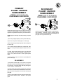
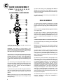
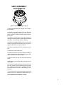
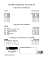
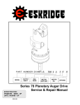
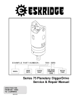
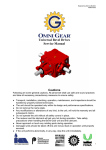
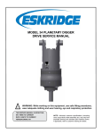
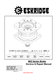
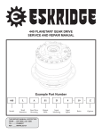
EXAMPLE PART NUMBER: SERIES MOUNTING FLANGE OUTPUT SHAFT INPUT MOUNTING 250 A D1 C 4 - 51 Z INPUT SPLINE RATIO OPTIONS Model 250 Planetary Geardrive Service & Repair Manual EFFECTIVE FOR: FROM S/N: 28500 TO: (CURRENT) (g250-a) Rev. A MODEL 250 SERVICE MANUAL DOUBLE PLANETARY GEARDRIVE This manual will assist in disassembly and assembly of the above model planetary geardrives. Item numbers, indicated in parentheses throughout this manual, refer to the exploded parts breakdown drawing. Individual customer specifications (mounting case, output shaft, brake assembly, etc.) may vary from exploded drawing and standard part numbers shown. If applicable, refer to individual customer drawing for details. For any spare or replacement parts, contact your distributor or equipment manufacturer. Always try to have available the geardrive unit part number, serial number and date code on the serial tag. This information may be necessary for verification of any component part numbers. Component part numbers and/or manufacturing lot numbers may be stamped on individual parts. This information may also be helpful in identifying replacement components. LUBRICATION & MAINTENANCE Change the oil after the first 50 hours of operation. Oil should be changed at 500 hour intervals thereafter. Use a GL5 grade EP 80/90 gear oil (EP = Extreme Pressure). The geardrive should be partially disassembled to inspect gears and bearings at 1000 hour intervals. If your unit was specified shaft up or with a -Z option, a grease zerk was provided in the base housing. For shaft-up operation, the output bearing will not run in oil and must be grease lubricated. Use a lithium base or general purpose bearing grease sparingly every 50 operating hours or at regular maintenance intervals. Over-greasing the output bearing tends to fill the housing with grease and thicken the oil. OPERATING POSITION Horizontal shaft Vertical shaft OIL CAPACITY 6.00 pints (2,8 liters) 10.0 pints (4,7 liters) WARNING: While working on this equipment, wear adequate protective clothing, hearing, eye, and respiratory protection. Use safe lifting procedures. UNIT DISASSEMBLY PROCEDURE (Refer to exploded view drawing on page 7) 1) Scribe a diagonal line across the outside of the unit from the cover (4) to the base (1) before disassembly to assure proper positioning of pieces during reassembly. 2) Remove magnetic drain plug (33) and drain oil from unit. Maximum drainage occurs when oil is warm. 3) Remove the twenty hex head capscrews (29) and lockwashers (32). 4) Remove the cover (4), thrust washer (28), input gear (11), and carrier thrust washer (14). Inspect o-ring (15); discard if damaged or if it has taken a set. 5) Lift the primary planet carrier assembly out of the unit (includes items 5, 10, 13, 16, 25, & 30). 2 OIL LEVEL To horizontal centerline of geardrive To midway on upper/primary gearset 6) If sun gear (9) has not been removed from geardrive, do so now. (Sometimes the sun gear remains in the primary carrier (5).) 7) Remove primary ring gear (2). Inspect second o-ring (15), as before; discard if damaged. 8) Remove carrier thrust washer (14). Lift the secondary planetary assembly out of the unit (includes items 6, 8, 12, 17, 23, 24, & 31). Use a puller if necessary. 9) Remove secondary ring gear (3). Inspect third o-ring (15), as before; discard if damaged. 10) The unit is now disassembled into groups of parts. The area(s) requiring repair should be identified by thorough inspection of the parts after they have been cleaned and dried. Then refer to the appropriate group repair section below. 1. Primary Planet Carrier subassembly 2. Secondary Planet Carrier subassembly 3. Base subassembly PRIMARY PLANET CARRIER SUBASSEMBLY (ITEMS 5, 10, 13, 16, 25, & 30) DISASSEMBLY AND REPAIR Rotate planet gears (10) to check for abnormal noise or roughness in bearings (25) or planet shafts (13). If further inspection or replacement is required, proceed as follows. NOTE: Support carrier (5) only while pressing out planet shafts. SECONDARY PLANET CARRIER SUBASSEMBLY (ITEMS 6, 8, 12, 17, 23, 24, & 31) DISASSEMBLY AND REPAIR Follow the same procedure as that for the primary planetary assembly. Substitute items as indicated: planet gears (8), planet bearings (23 & 24), planet shafts (12), roll pins (31), carrier (6) and washers (17). 1) Drive roll pins (30) completely into the planet shafts (13). 2) Press or drive planet shafts (13) out of carrier (5). 3) Remove planet gears (10) and planet washers (16) from the carrier (5). 4) If the planet bearings (25) require replacement, slide them out of the planet gears (10) and replace with new ones. 5) Check primary planet shafts (13) for any abnormal wear, especially ones where bearings needed to be replaced. If any abnormal wear is found, replace planet shafts. 6) Use 3/16 inch pin punch to remove roll pins (30) from planet shafts (13). RE-ASSEMBLY 1) With planet washers (16) on both sides of the planet gear (10) and with bearings (25) installed, slide gear into the carrier (5). Insert the planet shaft (13) through the carrier, washers, and planet gear. 2) Planet shafts (13) should be installed with chamfered end of 3/16 inch hole toward outside diameter of the carrier (5). This will aid in alignment of holes while inserting roll pins (30). 3) Drive a roll pin (30) through the carrier hole and into the planet shaft to retain the parts. Repeat for other planet gears. 3 BASE SUBASSEMBLY (ITEMS 1, 7, 18, 19, 20, 21, 22, 26, 27, 33, 35, & 36) DISASSEMBLY AND REPAIR 5) Press outer bearing cone (19) (large end down as shown) onto the shaft until it seats against the shoulder. Bearing cone (19) may be reused if it was removed only to replace the seal (35). 6) Inspect inner and outer bearing cups (20 & 22) and replace if necessary. BASE ASSEMBLY 1) Clean all foreign material from magnetic oil plug (33) located on side of base (1). Add a small amount of pipe thread compound to pipe plug before installing back into base. 2) Place the base (1) (output side up, opposite shown) on the press table. 3) Apply a layer of lithium or general purpose bearing grease to surface of outer bearing cup (20). Insert the shaft into the base (bearing cone down) and use a soft hammer to install the shaft seal (35) into the mounting base. CAUTION: Output shaft is not retained at this point. 4) Invert this assembly so it is standing on the shaft (on the press table). 1) Remove the shaft retaining ring (18). Remove the spacer (27) and shim(s) (26). CAUTION: Output shaft is no longer retained. Care should be taken not to injure feet because output shaft can fall out. Care should also be taken not to damage output shaft when shaft is pressed through base. 2) Output shaft removal. Base (1) should be set pinion side down, as shown, on a plate or table with output shaft (7) protruding through a hole in table. Press output shaft out bottom of base by applying a load to top end (internal end) of shaft until it passes through inner shaft bearing cone (21). 3) If outer bearing cone (19) (on the shaft) needs to be removed a gear puller may be used, otherwise skip to step number 6. If reusing old bearing cone, do not pull on or damage roller cage. Remove the shaft seal (35) for inspection or replacement. 4) Lubricate inner lip of new shaft seal (35) and slide the seal onto the shaft (7) until it fits snugly over shaft seal diameter with the open side toward the inside of the gearbox. NOTE: Press bearing cone onto output shaft by pressing on inner race only. DO NOT press on roller cage or it may damage bearing. 4 NOTE: Press bearing cone onto output shaft by pressing on inner race only. DO NOT press on roller cage or it may damage bearing. 5) Apply a layer of lithium or general purpose bearing grease to surface of inner bearing cup (22). Press the inner bearing cone (21) (large end up as shown) onto the shaft (7) until it is just seated against inner bearing cup (22). A slight preload of less than 100 in-lbs rolling torque should be obtained. 6) Relieve the press and slide the shim(s) (26) and the spacer (27) onto the shaft (7). Install the retaining ring (18) into the shaft groove. It is important that the retaining ring is completely seated in the groove. If the retaining ring cannot be installed into the groove, one shim must be removed and the procedure must be repeated. Once the retaining ring is installed, check for proper shaft bearing preload by pressing down on the end of the shaft and rotating the mounting base. There should be from 50 to 100 in-lbs of rolling resistance in the bearings. If the retaining ring is not tight against the spacer, remove the spacer and add one shim and repeat the procedure until the preload is acceptable. All subassembly service or repairs should be complete at this time. Continue on through UNIT ASSEMBLY to complete unit buildup. UNIT ASSEMBLY REASSEMBLING (Refer to exploded drawing on page 7) 1) When all subassemblies are complete, unit is ready to be assembled. 2) Lubricate o-ring (15) and install on the O.D. pilot of the secondary ring gear (3). Referring to scribe marks for proper orientation, install the secondary ring gear (3) onto the base (1). 3) Install the secondary planet carrier (6); assemble by rotating it until planet gears line up with ring gear teeth and shaft spline. Press until fully seated on shaft (7). 4) Lubricate o-ring (15) and install on the O.D. pilot of the primary ring gear (2) and install the primary ring gear (2). Refer to scribe marks for proper orientation. 5) Slide the sun gear (9) into the secondary planet carrier (6). 6) Install carrier thrust washer (14). 7) Install primary planet carrier (5); assemble by rotating it until planet gears line up with ring gear teeth and sun gear spline. Assembly should drop into place. 8) Slide the input gear (11) into the primary planetary carrier. 9) Install carrier thrust washer (14) and input gear thrust washer (28). 10) Lubricate o-ring (15) and install on the O.D. pilot of the cover (4). Position the cover (4) with the proper orientation. Install the twenty 5/8-11 capscrews (29) with lockwashers (32) and torque to 220 ft-lbs(dry), 170 ftlbs(lubed). 11) Fill to proper level, as specified on page 2, with EP 80/ 90 gear oil after unit is sealed with a brake and/or motor. THE GEARDRIVE IS NOW READY TO USE. 5 6 PRODUCT WARRANTY ESKRIDGE, INC. (Eskridge) warrants to its original purchaser (Customer) that new component parts (Parts) sold by Eskridge to the Customer will be free of defects in material and workmanship and will conform to standard specifications set forth in current Eskridge sales literature or to any custom specifications of the Customer acknowledged in writing by Eskridge, SUBJECT TO THE FOLLOWING QUALIFICATIONS AND LIMITATIONS: 1) Prior to placing warranted Parts in service, the Customer shall provide proper storage such that foreign objects (e.g., rain or debris) cannot enter any Parts via entry ports which are normally closed during operation. 2) If Parts requiring motorized power for operation are received from Eskridge without a motor, documentation must be available indicating proper lubrication upon placement of the Parts in service. 3) The Customer must notify Eskridge in writing of any claim for breach of this warranty promptly after discovery of a defect and in any event prior to the termination of the warranty period, which shall commence when a unit is placed in service and shall expire upon the earlier of (i) the expiration of twelve (12) months from the date of Commencement of Service (as defined in Paragraph 4) (ii) the completion of one thousand (1,000) hours of service of the Parts (iii) the expiration of six (6) months after the expiration of any express warranty relating to the first item of machinery or equipment in which the Parts are installed or on which it is mounted, or (iv) the installation or mounting of the Parts in or on an item of machinery or equipment other than the first such item in which the Parts are installed or on which the Parts are mounted. 4) Parts shall be deemed to have been place in service (the Commencement of Service) at the time the machinery or equipment manufactured or assembled by the Customer and in which the Parts are installed or on which the Parts are mounted is delivered to the Customers dealer or the original end-user, which ever receives such machinery or equipment first. 5) This warranty shall not apply with respect to Parts which, upon inspection by Eskridge, show signs of disassembly, rework, modifications or improper installation, mounting, use or maintenance. 6) Eskridge makes no warranty in respect to hydraulic motors mounted on any Parts. Failure of any such motor will be referred to the motor manufacturer. 7) Claims under this warranty will be satisfied only by repair of any defect(s) or, if repair is determined by Eskridge in its sole, absolute and uncontrolled discretion to be impossible or impractical, by replacement of the Parts or any defective component thereof. No cash payment or credit will be made for defective materials or workmanship. IN NO EVENT SHALL ESKRIDGE BE LIABLE FOR INCIDENTAL OR CONSEQUENTIAL DAMAGES OF ANY KIND OR NATURE, WHICH DAMAGES ARE HEREBY EXPRESSLY DISCLAIMED. 8) From time to time, Eskridge may make changes in the component parts manufactured by it without incorporating such changes in the component parts previously shipped. Such changes shall not constitute an admission by Eskridge of any defects or problems with previously manufactured component parts. 9) All freight charges on Parts returned for warranty service are the responsibility of the Customer. THE FOREGOING WARRANTY IS THE SOLE WARRANTY MADE BY ESKRIDGE WITH RESPECT TO ANY PARTS, AND IS IN LIEU OF ANY AND ALL OTHER WARRANTIES, EXPRESSED OR IMPLIED. THERE ARE NO WARRANTIES WHICH EXTEND BEYOND THE DESCRIPTION ON THE FACE HEREOF. WITHOUT LIMITING THE GENERALITY OF THE FOREGOING, ESKRIDGE EXPRESSLY DISCLAIMS ANY IMPLIED WARRANTY OF MERCHANTABILITY OR FITNESS FOR ANY PARTICULAR PURPOSE, REGARDLESS OF ANY KNOWLEDGE ESKRIDGE MAY HAVE OF ANY PARTICULAR USE OR APPLICATION INTENDED BY THE PURCHASER. THE SUITABILITY OR FITNESS OF THE PARTS FOR THE CUSTOMERS INTENDED USE, APPLICATION OR PURPOSE AND THE PROPER METHOD OF INSTALLATION OR MOUNTING MUST BE DETERMINED BY THE CUSTOMER. WARRANTY RETURN POLICY 1) 2) 3) All Parts shall be returned freight prepaid. Any Parts qualifying for warranty will be repaired with new Parts free of charge (except for freight charges as provided above). If parts are found to be operable, you have two options: a. The Parts can be returned to you with a service charge for inspection, cleaning, and routine replacement of all rubber components and any other parts that show wear; or b. We can dispose of the Parts at the factory if you do not wish it to be returned. NOTE: Any order of Parts by customer shall only be accepted by Eskridge subject to the terms stated herein. Any purchase order forms used by Customer (to accept this offer to sell) which contain terms contrary to, different from, or in addition to the terms herein shall be without effect, and such terms shall constitute material alteration of the offer contained herein under K.S.A 84-2-207 (2)(b), and shall not become part of the contract regarding the sale of the Parts. 7 OTHER ESKRIDGE PRODUCTS PLANETARY GEARDRIVES SERIES TORQUE RATING MAX. INTERMITTENT 20/28 SERIES 50 SERIES 60 SERIES 100 SERIES 130 SERIES 150 SERIES 250 SERIES 600 SERIES 1000 SERIES SERIES 90B 90BA 92B 93 95C 95W 98D 20,000-28,000 IN-LBS 50,000 IN-LBS 60,000 IN-LBS 100,000 IN-LBS 130,000 IN-LBS 150,000 IN-LBS 250,000 IN-LBS 600,000 IN-LBS 1,000,000 IN-LBS MULTIPLE DISC BRAKES TORQUE RATING SAE B SAE B ADJUSTABLE TORQUE SAE B LOW PROFILE FOR NICHOLS MOTORS SAE C WHEEL MOUNT SAE D TO 4,800 TO 4,800 TO 2,800 TO 6,100 TO 12,000 TO 21,000 TO 25,000 IN-LBS IN-LBS IN-LBS IN-LBS IN-LBS IN-LBS IN-LBS PLANETARY AUGER DRIVES (DIGGERS) SERIES D50 76 77 78 75 TORQUE RATING MODELS 1500, 2500 & 5000 MODELS BA & BC, TWO SPEED MODELS BA, BC & BD MODELS 35 & 48, TWO SPEED MODELS 38 & 51, TWO SPEED 1,500-5,000 FT-LBS 8,000-12,500 FT-LBS 6,000-12,500 FT-LBS 9,000-12,500 FT-LBS 16,500-20,000 FT-LBS Your nearest Eskridge Distributor is: 1900 Kansas City Road Olathe, Kansas 66061 phone (913) 782-1238 fax (913) 782-4206 WEBSITE: www.eskridgeinc.com E-MAIL: [email protected]