1
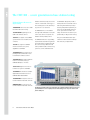
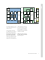
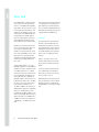
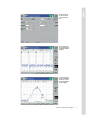
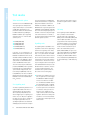
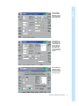
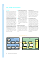
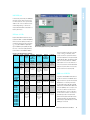
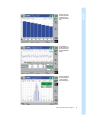
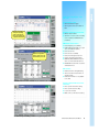
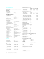
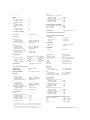
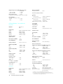
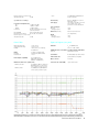
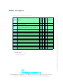
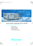
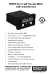
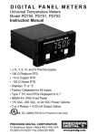
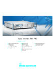
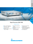
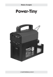
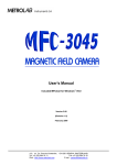
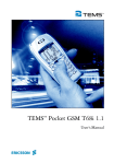
Universal Radio Communication Tester CMU300
The base station tester for current and future mobile radio networks
◆
◆
◆
◆
◆
Extremely high-speed testing
Highly accurate measurements
Modular future-proof design
Comprehensive spectrum analyzer and signal generator
Upgradability to 3rd generation technologies
The CMU300 – a new generation in base station testing
Rohde&Schwarz milestones in
digital testing
1990 CMTA94 The first test set for GSM
transmitter and receiver testing.
1991 CRTS02/04 Signalling tester for
GSM mobile and base stations.
1992 FTA Sole supplier of the GSM900
system simulator for conformance testing
of mobiles.
1993 ITA Sole supplier of GSM900
interim conformance test system,
upgradable to GSM1800.
Rohde & Schwarz has always been at the
forefront of mobile radio technology. For
more than 60 years now we are developing solutions for our customers.
The CMU300 carries on this tradition.
As a high-end communication tester platform for base stations it completes the
Rohde & Schwarz product portfolio.
The CMU300 reflects the long-standing
expertise Rohde & Schwarz has gained in
the world of mobile communication and
base station testing in different fields
such as production, R&D, commissioning,
system test, service and maintenance.
The CMU300 is designed to provide a
flexible platform for customized solutions
and testing with maximum speed, top
accuracy and optimum repeatability. Its
home is the world of digital mobile networks of generations 2 and 2.5. As a
today‘s investment in the future it is prepared already for 3rd generation testing.
Ask your local Rohde&Schwarz representative for a demonstration and help to
find out about your requirements.
1994 CMD55/57 The world‘s first compact digital radiocommunication tester
for GSM mobiles and base stations.
1996 CRTP/C02 Approved as standalone
tester for conformance testing of
GSM900/1800 phase II mobiles.
1997 TS8915 Supplier of the first conformance test system for GSM1900.
1997 CMD65 The world‘s first compact
digital radiocommunication tester for
GSM900/1800/1900 and DECT.
1999 CMU200 THE cellphone tester for
current and future mobile radio networks.
2000 CMU300 Base station tester for
current and future mobile radio networks.
The CMU300 can handle a wide range of applications, but is primarily optimized for the high accuracy and
speed demanded in an ever more quality-conscious manufacturing process. The picture shows the front
panel for desktop use
2
Universal Radio Communication Tester CMU300
CMU300
BTS
BSC
CMU
Abis interface
CMU - B71
CMU BER
analyzer
Signalling
CMU PN
generator
BTS PN
generator
Channel
decoder
CMU
BER loop
Channel
coder
Modulator
Demodulator
CMU RAW
BER loop
"burst by burst"
RF switching matrix
Modulator
RF
BTS RAW
BER loop
"burst by burst"
Demodulator
Frame clock
IN
Channel
coder
Frame clock
OUT
BSC PN
generator
BTS
BER
loop
Interface
board
Channel
decoder
BTS RAW
BER
analyzer
Control
of BTS/
setup of
channels
BSC BER
loop
BSC BER
analyzer
BTS BER
analyzer
MMI / LMT
controller
The CMU300 concept guarantees flexible adaptation to different customer-specific test environments, plus realtime channel coding/decoding capability
There are different approaches to testing
receiver and transmitter characteristics of
modern base stations.
The Universal Radio Communication
Tester CMU300 represents a unique compact test solution, based on a generalpurpose RF generator and RF analyzer in
conjunction with a powerful signalling
unit. The capability to generate and
decode signals for different channels in
realtime is the key argument for compact
one-box solutions. This is the main prerequisite for bit error rate (BER) tests and
signalling at higher layers; the tester is
able to simulate the functions of mobile
stations. The concept of the CMU300
allows easy adaptation to customer-specific BER test environments. Certain BER
signal paths are supported.
Additionally, for flexible connectivity to
possible RF interfaces of BTSs, the tester
incorporates a powerful, user-configurable RF switching matrix.
Universal Radio Communication Tester CMU300
3
Key strengths
The Radio Communication Tester
CMU300 ensures premium cost effectiveness through a variety of features, with
extremely fast measurement speed and
very high accuracy being the two most
important ones. In addition, the secondary remote addressing of the unit’s modular architecture makes for intelligent
and autonomous processing of complete
measurement tasks and fast control program design.
Greatest accuracy
In a production environment the unit’s
high accuracy allows DUTs (devices
under test) to be tested for optimal
mobile network performance. In the lab,
the CMU300 enables the development
engineer to replace conventional, dedicated premium-quality instruments more
often than any other radio communication tester and save desktop space at the
same time. High-precision measurement
correction over the whole frequency and
dynamic range as well as compensation
for temperature effects in realtime are
critical factors for achieving the
CMU300’s excellent accuracy.
The new, globally standardized
Rohde&Schwarz calibration system can
check the CMU300’s accuracy in a service
center close to you or, volume permitting,
on your premises. A worldwide network of
these standardized automatic calibration
systems has been implemented in our service centers. Highly accurate and repeatable calibration can be performed wherever
you are. Your local Rohde&Schwarz representative offers customized service contracts for the unit.
4
Universal Radio Communication Tester CMU300
Greatest speed
ProbeDSP™ technology
The high processing speed is due to
extensive use of ProbeDSP™ technology,
parallel measurements and innovative
remote command processing. These
three aspects of the performance of the
CMU300 are explained in more detail
below.
The modular architecture relies on decentralized ProbeDSP™ processing coordinated by a powerful central processor.
Like an oscilloscope probe, DSPs dedicated to a specific local data acquisition
and evaluation workload help to keep
subsystem performance at an uncompromised maximum even if additional modules are fitted to the CMU300 mainframe.
Key advantages of the CMU300
Speed
Single measurement up to 10 times faster
than with the previous generation of
instruments
Accuracy
Three times more accurate than the previous generation of instruments with excellent repeatability
Modularity
Modular hardware and software concept
provides easy extension to enhanced
functionality
Bullet-proof
Low component count, low power consumption, and effective heat conduction
result in unparalleled reliability
Future-proof
Easy migration to future standards
Innovative remote processing
Greatest reliability
The novel secondary addressing mode
can address similar functions of each of
the CMU300´s subsystems (different
mobile radio standards) in an almost
identical way. Using this type of addressing, new remote test sequences can be
programmed by a simple cut and paste
operation followed by editing specific
commands to adapt the control program
to the new application. Secondary
addressing is fully SCPI-compliant, which
means that a subsystem address, for
example "GSM1800", can be replaced by
a string denoting a different subsystem
(another mobile radio standard).
The keys to the high reliability of the
CMU300 are the low power intake and
the innovative cooling concept. Less
power means less heat. Power consumption is way below 200 W due to specially
selected low-power components, the
minimum component count concept, plus
low voltage design wherever possible.
The CMU300 employs an ultra-effective
heat management between housings
and individual components as well as
between heat sinks and air flow. Independent cooling cycles for the front module controller, the power supply unit and
the RF frontend add up to an optimized
cooling system.
Universal Radio Communication Tester CMU300
5
Base unit
As the CMU300 has a modular architecture, the base unit comes without any
network- or standard-specific hardware
and software. The base unit can be used
for testing the general parameters of RF
modules at early production stages. Constituent parts of the CMU300 base unit
are the RF generator and RF analyzer,
which are completed by a versatile network-independent time domain menu
and a comprehensive spectrum analyzer.
Besides the convenient operational concept, the spectrum analyzer stands out
for a continuous frequency range
(10 MHz to 2.7 GHz) and several selectable resolution bandwidths. The zero span
mode represents a separate operation
group with sophisticated trigger and timing functions (pre-trigger, delay; timebase; slope)
The RF switching matrix is one of the
CMU300´s highlights. It is located directly
behind the connectors and yields a superior VSWR of better than 1:1.2. With 4
flexible N connectors the instrument can
be easily adjusted to the DUT. Two connectors (RF1, RF2) are configurable as
duplex RF interfaces. One connector is for
high power base stations up to +47 dBm,
the other one is for micro base stations
with a maximum output power of
+33 dBm. In addition, the instrument is
equipped with a high power output (RF3
OUT; up to +13 dBm) and a sensitive
input (RF4 IN; –80 dBm to 0 dBm). So the
power of incoming RF signals can be analyzed in the range from +47 dBm down to
–80 dBm. For receiver tests signals from
–130 dBm up to +13 dBm can be generated.
6
Universal Radio Communication Tester CMU300
The rear-panel reference input and output
is the prerequisite for minimizing systematic frequency errors during measurement. It is fitted as standard. Besides the
IEEE and RS-232-C interface the base unit
is equipped with two PCMCIA slots.
Operation
The instrument can be operated either
manually or via the IEC/IEEE bus. The
hierarchical menu structures in conventional communication testers have been
replaced by context-sensitive selection,
entry and configuration pop-up menus,
which results in a uniquely flat menu
structure.
Thanks to the high resolution of the
extremely bright high-contrast TFT display even the finest details can be displayed.
To increase speed, measurements that
are not required can be switched off,
which frees resources for the measurement you want to focus on.
Advanced operational ergonomics have
been incorporated into a most compact
package. Even with the rackmount kit,
the CMU300 does not exceed four height
units.
The base unit incorporates generic RF analyzer / generator functions
The zero span mode of
the spectrum analyzer is
optimized for all kinds of
RF signals
The spectrum analyzer
provides several marker
functions for a comprehensive investigation of
the signal applied
Universal Radio Communication Tester CMU300
7
Test modes
Tailor-made with options
The basic version of the CMU300 already
offers signal generator and spectrum
analyzer functionality. It is converted into
a GSM radiocommunication tester
(transmitter and receiver measurements
for GMSK modulation) by adding the
CMU-B21 hardware option (signalling
unit) and at least one of the five GSM
software options.
◆
◆
◆
◆
◆
GSM400 (CMU-K30)
GSM850 (CMU-K34)
GSM900 (CMU-K31)
GSM1800 (CMU-K32)
GSM1900 (CMU-K33)
In this way – as an essential feature – all
GPRS channel coders are available in the
CMU300. The GSM functionalities can be
extended to EDGE (TX and RX test functionality) by means of the CMU-K41 software
option, which also adds EGPRS channel
coders. The CMU-K39 software option
allows link setup using the standard call
procedures MOC/MTC (mobile originated/
terminated call). The available hardware
options include a highly accurate, ovencontrolled crystal (CMU-B12) and an Abis
board (CMU-B71). The latter is needed for
BER tests where the bit pattern sent by the
CMU300 is returned to the CMU300 via
the Abis interface.
Non-signalling mode
This mode is particularly suitable for testing RF boards/modules with little or no
signalling activity. The measurement
starts completely independently from
external trigger signals or signalling information. As soon as RF power is applied to
the input, the tester starts to sample the
incoming RF signal. When the corresponding RF parameters are calculated
and displayed, the instrument is ready for
8
Universal Radio Communication Tester CMU300
the next measurement. All GSM/EDGEspecific TX measurements on signals with
appropriate modulation scheme and
midamble are available. In addition, the
CMU300 is able to generate signals with
GSM/EDGE-specific midamble and modulation in the entire frequency range from
10 MHz to 2.7 GHz. The analyzer and generator functionalities are not linked, i.e.
any channel spacing between uplink and
downlink signals is possible.
Signalling mode
The signalling mode is provided for testing modules or base stations supporting a
certain level of signalling. In this mode,
the tester operates synchronously to the
BTS, i.e. it is synchronized to the TDMA
frame structure, which is vital for receiver
bit-error-rate measurement. All transmitter parameters can be tested separately
for each timeslot. This function is necessary for testing base stations that support
both GSM and EDGE. The ability to code /
decode channels in realtime is the basis
for synchronized measurements. The
instrument can be synchronized to the
base station in the following ways:
◆ If the BTS has a multiframe clock output, the signal can be used to trigger
the CMU300. An additional trigger
line has to be taken into consideration. For BER tests and EDGE TX tests
the 26 multiframe trigger is required.
◆ If only the RF connection is used, the
tester can synchronize to the C0 carrier of the base station, just like a mobile phone. This simplifies the test
setup. However, a CCH carrier including FCCH / SCH channels and system
information 1 to 4 must be activated
in the BTS before measuring the used
traffic channel.
After successful synchronization there is
permanent resynchronization to SACCH
of TCH.
Call setup
In the signalling mode the CMU300 is
able to provide a mobile simulation
(optional) with mobile originated call
(MOC), mobile terminated call (MTC) and
location update procedures. This is necessary whenever the complete signalling
of the BTS air interface is to be tested, the
BTS is in slow frequency hopping (SFH)
mode or the BTS measurement reports
have to be checked. During location
update, MOC and MTC, the layer 3 messages exchanged between the CMU300
and the base station are shown on the
TFT display. The IMEI and IMSI numbers
of the simulated mobile (CMU300) must
be entered manually, no SIM card being
used.
The non-signalling
mode allows GMSK/
8PSK signals to be generated and analyzed for
RX/TX module testing
The signalling mode
overview menu informs
the user quickly and
comprehensively about
the BTS’s TCH RF performance; the hotkeys
at the bottom of the
screen give immediate
access to specific measurements
There are different possibilities for setting up
the channel to be measured in the Connection
Control pop-up menu
Universal Radio Communication Tester CMU300
9
RX (BER) measurements
Principles
When it comes to receiver characteristics,
the physical effects appear in the DUT
itself, so no direct measurement is possible. The GSM standardization committees
therefore defined test methods for measuring the receiver characteristics of
GSM/EDGE BTSs. According to these test
methods there are two logical reference
points inside the BTS where the receiver
quality must be defined. These reference
points are located behind the demodulator and behind the channel decoder. The
basic principle of bit error rate (BER) testing is simple. The CMU300 sends a data
stream to the BTS, which then sends it
back to the tester (loop); i.e. the signal to
be analyzed is forwarded from the reference point inside the BTS to the external
BER analyzer by means of different loops.
The CMU300 compares the sent and
received uncoded data bits to determine
the number of bit errors. Two essentially
different loops are used:
◆ The BTS is set to close its RF loop directly after the logical reference
points. The received data is returned
on the RF downlink path. The benefit
of this measurement principle is that
no extra cabling is needed, besides
the "ordinary" RF connection. This approach is an easy way of testing the
most important GSM/EDGE channel
types.
◆ Using the Abis loop the decoded signal
is forwarded to the BER analyzer via
the Abis output of the BTS. This test
path is often required when there is
no possibility for loop activation inside
the BTS.
Absolute receiver sensitivity
Based on realtime BER capability the user
can directly vary the transmitter level during the test by means of numerical entry
or the spinwheel. This is a fast and easy
way to determine absolute receiver sensitivity.
Receiver stress test
For this application the CMU300 provides
different transmitter levels for the active
timeslot and for the unused timeslots
(dummy bursts). The receiver in the BTS
can thus be subjected to unfavourable
conditions in the unused timeslots.
Pseudo-random bit streams
The tester uses a choice of four true
pseudo-random bit sequences for BER
measurement. You will especially appreciate this feature if you have ever overlooked a faulty channel coder by using a
fixed bit pattern, because a pseudo-random sequence is the only reliable means
of detecting it. For transmitter measurements the BTS RF loop can also be kept
closed outside BER measurements. This is
a simple way of providing the transmitter
signal modulated with pseudo-random
bits required for spectrum and power
measurements.
Abis loop (BER, RBER, FER)
CMU300
BTS
BER analyzer
Abis
RF IN
BER analyzer
Channel decoder
Demodulator
Modulator
RF loop
RAW BER
RF OUT
PN generator
Channel coder
Modulator
BER test environment
10
Universal Radio Communication Tester CMU300
Demodulator
Channel coder
BER
RBER
FER
DBLER
Channel decoder
Interface
board
RAW BER test
In the burst by burst mode, the CMU300
transmits only bits without error protection like class II bits. The loop in the BTS
under test has to be closed before channel decoding/coding, so raw bits are
measured and the BER is evaluated on a
burst by burst basis.
BER test of TCHs
Circuit-switched traffic channels can be
tested in the BER or residual BER (RBER)/
frame erasure rate (FER) test modes. The
instrument supports the RF loop and the
Abis loop (option CMU-B71 required). A
cyclic redundancy check (CRC) excludes
bit errors on the return path (downlink)
from the BTS to the CMU300. Addition-
Receiver Quality (TCH) menu; RF loop; RBER / FER mode
Overview of the CMU300 BER test capabilities
Channel type
–
TCH/FS TCH/
HS TCH/EFS
Possible
tests
Supported
Supported Channel setup
BTS/BSC loops "inside" procedure
loops
CMU
(CMU300 as
RF loop)
Required
options
(in addition to
CMU-B21)
Comments
Burst by
BTS loop
CMU RAW Forced channel CMU-K30 to -K34 GMSK and
burst demodulator/ BER loop
setup without and CMU-K41
8PSK
(RAW BER) modulator (only TCH/FS)
signalling
(CMU-K41
supported
optional for 8PSK)
BER /
BTS (BSC) CMU BER loop Forced channel CMU-K30 to -K34;
RBER / BER loop with with channel setup without (CMU-B71 and
FER
channel dedecoding
call procedure
CMU-K39
coding; (op(optional, MOC/
optional)
tional loop via
MTC)
Abis)
TCH/F14.4
TCH/9.6 TCH/
F4.8 TCH/H4.8
TCH/H2.4
BER
E-TCH/
F43.2 NT
BER
PDTCH-CS1
PDTCH-CS2
PDTCH-CS3
PDTCH-CS4
BER/
DBLER
PDTCH-MCS1
PDTCH-MCS2
PDTCH-MCS3
PDTCH-MCS4
PDTCH-MCS5
PDTCH-MCS6
PDTCH-MCS6
PDTCH-MCS7
PDTCH-MCS8
PDTCH-MCS9
BER/
DBLER
BTS (BSC) CMU BER loop Forced channel CMU-K30 to -K34 Special BTS
BER loop with with channel setup without
test mode
channel
decoding
signalling
required
decoding
BTS (BSC)
BER loop with
channel decoding
BTS BER loop
with channel
decoding,
without RLC
MAC
BTS BER loop
with channel
decoding,
without RLC
MAC
–
Forced channel CMU-K30 to -K34 Special BTS
setup without and CMU-K41
test mode
signalling
required
–
Forced channel CM-K30 to -K34 Special BTS
setup without
test mode
signalling (one
required
static TS active
on up-/downlink)
–
Forced channel CM-K30 to -K34 Special BTS
setup without and CMU-K41
test mode
signalling (one
required
static TS active
on up-/downlink)
ally, the instrument itself can be used as
a loop on the Um air interface, which
means that it can loop back information
from the RF downlink to the uplink including decoding/coding. The BER result indicates errors of class Ib/II bits. In RBER/
FER mode the errors of class Ib/II bits of
non-erroneous frames are calculated and
furthermore, frames with erroneous class
Ia bits are taken into account (FER).
BER test of PDTCHs
For packet-switched data traffic channels
the bit error rate test is modified in such a
way that the BTS loops back the received
data packets on a block by block basis
(loop behind channel decoder required)
and measures the BER and the data block
error rate (DBLER). The test setup is similar to the one which is used on circuitswitched channels. The test is based on
an RF connection, where one timeslot is
permanently used on the uplink and
downlink with packet-switched channel
coding being active. No attach/detach
functionality is required because no RLC/
MAC layer is involved.
Universal Radio Communication Tester CMU300
11
TX measurements
GMSK
Power measurements
Phase and frequency error
The signal power received from the base
station is displayed as a function of time
(burst analysis) over one burst period. The
measurement graph can be further processed to determine an average, minimum or maximum result as well as to calculate the average over the whole burst.
In addition to the burst power measurement, a limit check with tolerances is performed. The displayed continuous measurement is derived from 668 equidistant
measurement points with a ¼ bit spacing, covering a time range of 156 ¾ bit.
The actual phase of the signal received
from the base station is recorded during
the entire burst and stored. The transferred data is demodulated and the training sequence searched for. The middle of
the training sequence (transition between
bits 13 and 14) is used for time synchronization.
The complete data content of the burst is
then mathematically modulated using an
ideal modulator. The resulting ideal phase
is compared with the measured phase.
From the difference between the two
quantities (the phase difference trajectory), a regression line is calculated using
the mean square error method. The phase
error is the difference between the phase
difference trajectory and the regression
line; it is calculated and plotted over the
whole useful part of the burst. The average frequency error in the burst is equal
to the derivative of the regression line
with respect to time.
The CMU300 evaluates the phase error
with a resolution of 4 measured values
per modulated bit, which corresponds to
a sampling rate of approx. 1 MHz.
Spectrum measurements
The spectrum measurement serves to
measure the amount of energy that spills
out of the designated radio channel when
the base station transmits with predefined output power. The measurement is
performed in the time domain mode, at a
series of frequency points symmetrically
distributed all around the nominal frequency of the designated channel.
12
Universal Radio Communication Tester CMU300
In the signalling mode only, a second
application is available – the power versus slot measurement. The power versus
slot measurement determines the average burst power in all eight timeslots of a
TDMA frame. The average is taken over a
section of the useful part of the burst; it is
not correlated to the training sequence.
The result is displayed as eight bar
graphs, one for each time slot of a single
frame, providing the possibility of measuring a very large number of bursts in
extremely short time. Therefore this application is suitable whenever the behaviour
or the stability of the average burst power
in consecutive timeslots is to be monitored. Another highlight of this measurement is the fact that power results are
available almost in realtime. The power
versus time measurement however
returns the current, average, maximum
and minimum value within a statistic
cycle.
The power versus slot
measurement provides
information about 8
power steps simultaneously
The signalling mode
provides timeslot-selective measurements for
power and modulation
analysis
Due to the FFT approach
the spectrum analysis
can be performed at
unprecedented speed
Universal Radio Communication Tester CMU300
13
TX measurements
8PSK
8PSK/EDGE is another step towards
increasing the mobile radio data rate. By
using the available GSM frame structure,
the gross data rate is three times that
obtained with GMSK. The CMU300 can
already perform 8PSK on GSM bursts and
analyze them thanks to advanced measurement applications. Error vector magnitude and magnitude error have been
added to the range of modulation measurements. New templates for power versus time measurements ensure compliance with the specifications, as do the
modified tolerances for spectrum measurements. As with all measurements
provided by the CMU300, special attention has been given to achieving maximum measurement accuracy and speed
for EDGE too. All measurement tolerances
are set by default to GSM recommendation 11.21 but may of course be altered to
suit individual needs.
Modulation analysis
For the modulation analysis the actual
modulation vector of the signal received
from the base station is measured over
the complete burst and stored. The following non-redundant quantities are calculated on the basis of a comparison of
this vector with the computed ideal signal
vector:
◆ Phase error
The phase error is the difference between the phases of measured and
the ideal signal vector.
◆ Magnitude error
The magnitude error is the difference
between the magnitudes of the measured and the ideal signal vector.
◆ Error vector magnitude (EVM)
The EVM is the magnitude of the vector connecting the measured and the
ideal signal vector. In contrast to the
previous quantities, the EVM cannot
be negative. These three quantities
14
Universal Radio Communication Tester CMU300
are calculated as a function of time
and displayed over the whole useful
part of the burst (symbols 6 to 162),
each of them in a separate graphical
measurement menu. In addition, the
peak and RMS values of all three
quantities are calculated (over the
whole display range or over the first
ten symbols only) and displayed.
Finally, the modulation analysis provides
the following scalar quantities:
◆ 95:th percentile
Limit value below which 95% of the
values of a measurement graph are
located. The 95:th percentile of a
measured quantity has the same unit
as the quantity itself. The CMU300
determines 95:th percentiles for EVM,
magnitude error and phase error.
◆ Origin offset
The origin offset in the I/ Q constellation diagram reflects a DC offset in
the baseband signal. The origin offset
corresponds to an RF carrier feedthrough.
◆ I/Q imbalance
Amplitude difference between the inphase (I) and the quadrature (Q) components of the measured signal, normalized and logarithmic. The I/ Q imbalance corresponds to an unwanted
signal in the opposite sideband.
◆ Frequency error
Difference between the measured frequency and the expected frequency.
For the tolerance check all three
phase error graphs can be fitted into a
tolerance template and checked.
Power measurements
The 8 PSK power versus time measurement results are similar to the GMSK
measurement results. With 8PSK modulation the time axis is scaled in symbol
points. 8PSK symbols and GMSK bits
have the same transmission rate.
Owing to the characteristics of 8PSK
modulation, the amplitude of the RF signal
varies according to the data transmitted.
The average setting ensures that a correct reference power is used, the results
being averaged, however, over a longer
measurement time. In data-compensated
mode, a known data sequence is used to
correct the measured average power of
the current burst and estimate the correct
reference power.
GSM/EDGE highlights of the
CMU300
Synchronization to BTS
◆ Via BTS multiframe trigger
◆ Via RF synchronization procedure to
CCH
The data-compensated
mode (patent pending)
yields a stable average
burst power readout after
a singleshot measurement
Activation of channel to be measured
◆ Without call procedure
◆ Simulation of mobile station including
location update and MOC/MTC call
procedures
Different graphical functions (marker, limit line) are available for power versus time
measurement
Sophisticated algorithms
make for approx. up to 100
measurements per second
GMSK/8PSK measurements
◆ Phase/frequency error (GMSK)
◆ EVM including magnitude error, origin
offset, I/Q imbalance (8PSK)
◆ Power versus time
◆ Power versus slot (GMSK)
◆ Peak power/average burst power
◆ General spectrum measurements
◆ RAW BER, BER, RBER/FER measurements on circuit-switched channels
◆ BER/DBLER measurements on packetswitched channels
More features
◆ Realtime channel coding/decoding
◆ Timeslot-selective measurements in
signalling mode
◆ Flexible RF interface for easy adaptation to DUT
The Modulation Overview 8PSK menu selects all scalar modulation results to be displayed
Support of different BER test environments/loops
◆ BTS loop without channel coding
◆ BTS loop with channel coding
◆ Loop via Abis interface
◆ CMU as RF loop with channel coding
The error vector magnitude hotkey gives access to the graphical display
Universal Radio Communication Tester CMU300
15
Base unit specifications
Please see standard-specific data on the previous pages for more details and
improved accuracy.
Timebase TCXO
Max. frequency drift
in temperature range
+5°C to +45°C
Max. aging
±1 x 10⁻⁶
±1 x 10⁻⁶/year
Timebase OCXO – option CMU-B11
Max. frequency drift
in temperature range
+5°C to+45°C
±1 x 10⁻⁷
Max. aging
±2 x 10⁻⁷/year,
±5 x 10⁻⁹/day
after 30 days of operation
Warmup time (at +25°C)
approx. 5 min
Timebase OCXO – option CMU-B12
Max. frequency drift
in temperature range
+5°C to +45°C
with instrument orientation
referred to turn-off frequency
after 2 h warmup time following
a 24 h off time at +25°C
Max. aging
Warmup time (at +25°C)
Reference frequency inputs/outputs
Synchronization input
Frequency
Sinewave
Squarewave (TTL level)
Max. frequency variation
Input voltage range
Impedance
Synchronization output 1
Frequency
Output voltage
Impedance
Synchronization output 2
Frequency
Output voltage (f ≤13 MHz)
Impedance
±5 x 10⁻⁹, referred to +25°C
±3 x 10⁻⁹
±5 x 10⁻⁹
±3.5 x 10⁻⁸/year,
±5 x 10⁻¹⁰/day
after 30 days of operation
approx. 10 min
BNC connector REFIN
1 MHz to 52 MHz, step 1 kHz
10 kHz to 52 MHz, step 1 kHz
±5 x 10⁻⁶
0.5 V to 2 V, rms
50 Ω
BNC connector REFOUT1
10 MHz from internal reference or frequency at synchronization input
>1.4 V, peak-peak
50 Ω
BNC connector REFOUT2
net-specific frequencies in range
100 kHz to 40 MHz
>1.0 V, peak-peak
50 Ω
RF generator
Frequency range
Frequency resolution
Frequency uncertainty
Frequency settling time
100 kHz to 2700 MHz
0.1 Hz
same as timebase + resolution
<400 µs to ∆f <1 kHz
Output level range
RF1
100 kHz to 2200 MHz
2200 MHz to 2700 MHz
Output level uncertainty
RF1, RF2 (temperature range +23°C to +35°C)
>-106 dBm >-117 dBm -117 to 130dBm
10 MHz to 450 MHz
<0.6 dB
<1.5 dB1)2)
450 MHz to 2200 MHz
<0.6 dB
<0.6 dB2)
2200 MHz to 2700 MHz
<0.8 dB
<0.8 dB2)
<1.5 dB1)2)
RF1, RF2 (temperature range +5°C to +45°C)
>-106 dBm >-117 dBm -117 to 130dBm
10 MHz to 450 MHz
<1.0 dB
<1.5 dB1)2)
450 MHz to 2200 MHz
<1.0 dB
<1.0 dB2)
2200 MHz to 2700 MHz
<1.5 dB
<1.5 dB2)
<1.5 dB1)2)
RF3OUT in temperature range +23°C to +35°C
10 MHz to 450 MHz: –80 dBm to +10 dBm
450 MHz to 2200 MHz: –90 dBm to +10 dBm
2200 MHz to 2700 MHz: –90 dBm to +5 dBm
<0.8 dB
<0.8 dB
<1.0 dB
RF3OUT in temperature range +5°C to +45°C
10 MHz to 450 MHz:–80 dBm to +10 dBm
450 MHz to 2200 MHz: –90 dBm to +10 dBm
2200 MHz to 2700 MHz: –90 dBm to +5 dBm
<1.0 dB
<1.0 dB
<1.5 dB
Output level settling time
<4 µs
Output level resolution
0.1 dB
Generator RF level repeatability
(RF1, RF2, RF3, typical values after 1 h warmup):
Output ≥–80 dBm
0.01 dB
Output <–80 dBm
0.1 dB
VSWR
RF1
10 MHz to 2000 MHz
2000 MHz to 2200 MHz
2200 MHz to 2700 MHz
RF2
10 MHz to 2200 MHz
2200 MHz to 2700 MHz
RF3OUT
10 MHz to 2200 MHz
2200 MHz to 2700 MHz
<1.2
<1.3
<1.6
<1.2
<1.6
<1.5
<1.7
Attenuation of harmonics (f0 = 10 MHz to 2200 MHz, up to 7 GHz)
RF1, RF2
>30 dB
RF3OUT (P ≤+10 dBm)
>20 dB
Attenuation of nonharmonics
10 MHz to 2200 MHz
at >5 kHz from carrier
>40 dB
Phase noise (single sideband, f <2.2 GHz)
Carrier offset
20 kHz to 250 kHz
<−100 dBc (1 Hz)
≥250 kHz
<−110 dBc (1 Hz)
Residual FM
30 Hz to 15 kHz
CCITT
<50 Hz (rms), <200 Hz (peak)
<5 Hz (rms)
−130 dBm to −27 dBm
−130 dBm to −33 dBm
Residual AM
CCITT
<0.02% (rms)
RF2
100 kHz to 2200 MHz
2200 MHz to 2700 MHz
−130 dBm to −10 dBm
−130 dBm to −16 dBm
IQ modulation
Data for frequency offset range 0 kHz to ±135 kHz
Carrier suppression
>40 dB
RF3OUT
100 kHz to 2200 MHz
2200 MHz to 2700 MHz
−90 dBm to +13 dBm
−90 dBm to +5 dBm
1)
2)
16
Universal Radio Communication Tester CMU300
Valid for RF1 only.
Not valid at frequencies of net-clock harmonics.
RF analyzer
VSWR
RF1
10 MHz to 2000 MHz
2000 MHz to 2200 MHz
2200 MHz to 2700 MHz
RF2
10 MHz to 2200 MHz
2200 MHz to 2700 MHz
RF4IN
10 MHz to 2200 MHz
2200 MHz to 2700 MHz
<1.2
<1.3
<1.6
<1.2
<1.6
<1.5
<1.6
RF4IN
in temperature range +23°C to +35°C
50 MHz to 2200 MHz
2200 MHz to 2700 MHz
in temperature range +5°C to +45°C
50 MHz to 2200 MHz
2200 MHz to 2700 MHz
<0.7 dB
<0.9 dB
<1.0 dB
<1.1 dB
RF level measurement repeatability
(RF1, RF2, RF4, typical values after 1 h warmup):
Input >= –40 dBm
0.01 dB
Input <–40 dBm
0.03 dB
Level resolution
0.1 dB (0.01 dB via remote control)
Power meter (wideband)
Demodulation (data of hardware paths)
Frequency range
100 kHz to 2700 MHz
Level range
RF1
Continuous power3)
100 kHz to 2200 MHz
2200 MHz to 2700 MHz
Peak envelope power 4) (PEP)
RF2
Continuous power
100 kHz to 2200 MHz
2200 MHz to 2700 MHz
Peak envelope power 4) (PEP)
RF4IN (continuous power and PEP)
100 kHz to 2200 MHz
2200 MHz to 2700 MHz
Level uncertainty
RF1
50 MHz to 2700 MHz
RF2
50 MHz to 2700 MHz
RF4IN
10 MHz to 2700 MHz
+6 dBm to +47 dBm (50 W)
+10 dBm to +47 dBm (50 W)
+53 dBm (200 W)
−8 dBm to +33 dBm (2 W)
−4 dBm to +33 dBm (2 W)
+39 dBm (8 W)
−33 dBm to 0 dBm
−29 dBm to 0 dBm
+10 dBm to +20 dBm +20 dBm to +47 dBm
<1.0 dB6)
<0.5 dB5) 6)
−4 dBm to +6 dBm
+6 dBm to +33 dBm
<1.0 dB6)
<0.5 dB6)
−29 dBm to −19 dBm
−19 dBm to 0 dBm
<1.5 dB
<0.8 dB
Level resolution
0.1 dB (0.01 dB via remote control)
Power meter (frequency-selective)
Frequency range
Frequency resolution
Resolution bandwidths
Level range
RF1
Continuous power3)
10 MHz to 2200 MHz
2200 MHz to 2700 MHz
Peak envelope power 4) (PEP)
RF2
Continuous power
10 MHz to 2200 MHz
2200 MHz to 2700 MHz
Peak envelope power4) (PEP)
RF4IN (continuous power and PEP)
10 MHz to 2200 MHz
2200 MHz to 2700 MHz
Level uncertainty
RF1, RF2
in temperature range +23°C to +35°C
50 MHz to 2200 MHz
2200 MHz to 2700 MHz
in temperature range +5°C to +45°C
50 MHz to 2200 MHz
2200 MHz to 2700 MHz
3)
4)
5)
6)
10 MHz to 2700 MHz
0.1 Hz
10 Hz to 1 MHz in 1/2/3/5 steps
−40 dBm to +47 dBm (50 W)
−34 dBm to +47 dBm (50 W)
+53 dBm (200 W)
−54 dBm to +33 dBm (2 W)
−48 dBm to +33 dBm (2 W)
+39 dBm (8 W)
−80 dBm to 0 dBm
−74 dBm to 0 dBm
<0.5 dB
<0.7 dB
<1.0 dB
<1.0 dB
50 W in temperature range +5 °C to +30 °C, linear degradation down to 25 W at +45 °C.
Mean value of power versus time must be equal or less than allowed continuous power.
Calibrated for P >33 dBm only in frequency range 800 MHz to 2000 MHz.
Temperature range +5°C to +23 °C or +35 °C to +45 °C and f >2200 MHz: add 0.2 dB.
Phase noise (single sideband, f <2.2 GHz)
Carrier offset
20 kHz to 250 kHz
<−100 dBc (1 Hz)
250 kHz to 400 kHz
<−110 dBc (1 Hz)
≥400 kHz
<−118 dBc (1 Hz)
Residual FM
30 Hz to 15 kHz
CCITT
<50 Hz (rms), <200 Hz (peak)
<5 Hz (rms)
Residual AM
CCITT
<0.02% (rms)
Spectrum analyzer
Frequency range
Span
Frequency resolution
Resolution bandwidths
Sweep time
Display
Marker
Display line
Display scale
10 MHz to 2.7 GHz
zero span to full span
0.1 Hz
10 Hz to 1 MHz in 1/2/3/5 steps
≥100 ms, depending on RBW
560 dots, horizontal
up to 3, absolute/relative
1
10/20/30/50/80/100 dB
Level range
RF1
Continuous power3)
Peak envelope power4) (PEP)
RF2
Continuous power
Peak envelope power4) (PEP)
RF4IN (continuous power and PEP)
Level uncertainty
RF1, RF2
in temperature range +23°C to +35°C
50 MHz to 2200 MHz
2200 MHz to 2700 MHz
in temperature range +5°C to +45°C
50 MHz to 2200 MHz
2200 MHz to 2700 MHz
RF4IN
in temperature range +23°C to +35°C
50 MHz to 2200 MHz
2200 MHz to 2700 MHz
in temperature range +5°C to +45°C
50 MHz to 2200 MHz
2200 MHz to 2700 MHz
up to +47 dBm (50 W)
up to +53 dBm (200 W)
up to +33 dBm (2 W)
up to +39 dBm (8 W)
up to 0 dBm
<0.5 dB
<0.7 dB
<1.0 dB
<1.0 dB
<0.7 dB
<0.9 dB
<1.0 dB
<1.1 dB
Reference level for full dynamic range (low-noise mode)
Logarithmic level display
RF1
+10 dBm to +47 dBm
RF2
−4 dBm to +33 dBm
RF4IN
−22 dBm to 0 dBm
Universal Radio Communication Tester CMU300
17
Displayed average noise level (RBW 1 kHz, low-noise mode)
RF1/RF2/RF4IN
10 MHz to 2200 MHz
<−100 dBc
2200 MHz to 2700 MHz
<−95 dBc
Inherent spurious response
<−50 dB
Low distortion mode, f >20 MHz to 2200 MHz, except 1816.115 MHz
Inherent harmonics
(f0 = 50 MHz to 2200 MHz, up to 7 GHz)
RF1, RF2
<−30 dB
RF4IN
<−20 dB
GSM specifications – base station test
RF generator
Modulation
GMSK, BxT = 0.3
8PSK7)
Measurement bandwidth
in measurement menus
500 kHz
Power meter (frequency-selective)
Level range
RF1
Continuous power8)
Peak envelope power9) (PEP)
RF2
Continuous power
Peak envelope power9) (PEP)
RF4IN (continuous power and PEP)
−54 dBm to +33 dBm (2 W)
+39 dBm (8 W)
−80 dBm to 0 dBm
Level uncertainty
RF1, RF2, RF4IN
in temperature range
+23°C to +35°C
+5°C to +45°C
<0.5 dB
<0.7 dB
Level resolution
0.1 dB (0.01 dB via remote control)
−40 dBm to +47 dBm (50 W)
+53 dBm (200 W)
Frequency range
GSM400
GSM850
GSM900
GSM1800
GSM1900
450 MHz to 458 MHz/478 MHz to 486 MHz
824 MHz to 849 MHz
876 MHz to 915 MHz
1710 MHz to 1785 MHz
1850 MHz to 1910 MHz
Attenuation of inband
spurious emissions
>50 dB
Inherent phase error (GMSK)
Inherent EVM (8PSK)7)
Inherent EVM (8PSK)7)
<1°, rms
<4°, peak
<2%, rms
<0.6°, rms
<2°, peak
<1,0%, rms
Frequency measurement
uncertainty
<500 µs to res. phase of 4°
≤10 Hz + drift of timebase
Frequency settling time
Inherent phase error (GMSK)
Modulation analysis
Level range (PEP)
RF1
RF2
RF4IN
−6 dBm to +53 dBm
−20 dBm to +39 dBm
−60 dBm to 0 dBm
Burst power measurement
Output level range (GMSK)
RF1
RF2
RF3OUT
−130 dBm to −27 dBm
−130 dBm to −10 dBm
−90 dBm to +13 dBm
Output level range (8PSK)7)
RF1
RF2
RF3OUT
−130 dBm to −31 dBm
−130 dBm to −14 dBm
−90 dBm to +9 dBm
Output level resolution
0.1 dB
Level uncertainty
RF1, RF2: P >−117 dBm
in temperature range
+23°C to +35°C
+5°C to +45°C
RF3OUT
P >−90 dBm to +10 dBm (GMSK)
P >−90 dBm to +6 dBm (8PSK)7)
in temperature range
+23°C to +35°C
+5°C to +45°C
<0.5 dB
<0.7 dB
7)
18
Reference level for full dynamic range (8PSK, low-noise mode)7)
RF1
+6 dBm to +49 dBm
RF2
−8 dBm to +35 dBm
RF4IN
−26 dBm to –4 dBm
Dynamic range
>69 dB (BW= 500 kHz, rms)
Relative measurement uncertainty
Result >−40 dB
<0.1 dB
−60 dB ≤ result ≤−40 dB
<0.5 dB
Resolution
Spectrum due to modulation
<0.7 dB
<0.9 dB
RF analyzer
Frequency range
GSM400
GSM850
GSM900
GSM1800
GSM1900
Reference level for full dynamic range (GMSK, low-noise mode)
RF1
+10 dBm to +53 dBm
RF2
−4 dBm to +39 dBm
RF4IN
−22 dBm to 0 dBm
Dynamic range (GMSK)
>72 dB (BW= 500 kHz, rms)
460 MHz to 468 MHz/488 MHz to 496 MHz
869 MHz to 894 MHz
921 MHz to 960 MHz
1805 MHz to 1880 MHz
1930 MHz to 1990 MHz
With option CMU-K41.
Universal Radio Communication Tester CMU300
0.1 dB in active part of burst
10)
Level range for full dynamic range
RF1
RF2
RF4IN
Test method
Filter bandwidth
Measurement at an offset of
8)
9)
10)
+10 dBm to +47 dBm
−4 dBm to +33 dBm
−22 dBm to 0 dBm
relative measurement, averaging
30 kHz resolution filter (5 pole)
100, 200, 250, 400, 600, 800, 1000, 1200,
1400, 1600, 1800 kHz
50 W from +5 °C to +30 °C, linear degradation down to 25 W at +45 °C.
Mean value of power versus time must be equal or less than allowed continuous power.
The specifications apply to all cases in which interfering carriers (up to the same level as the
measured carrier) are more than 50 GSM channels away.
Dynamic range (noise correction mode)
with offset ≥1200 kHz
>80 dB
Spectrum due to switching
meets DIN IEC 68-2-27, MIL-STD-810D
40 g shock spectrum
Electrical safety
10)
IEC1010-1, DIN EN61010-1, UL3111-1,
CSA22.2 No. 1010-1
100 V to 240 V ± 10% (AC), 3.1 A to 1.3 A,
50 Hz to 400 Hz −5% to +10%
power factor correction, EN61000-3-2
Power supply
Level range for full dynamic range
RF1
RF2
RF4IN
Test method
+10 dBm to +47 dBm
−4 dBm to +33 dBm
−22 dBm to 0 dBm
absolute measurement, max. hold over
several measurements
Filter bandwidth
30 kHz resolution filter (5 pole)
Measurement at an offset of
400, 600, 800, 1200, 1800 kHz
Dynamic range (noise correction mode)
with offset ≥1200 kHz
>80 dB
General data
Rated temperature range
Storage temperature range
Humidity
Shock
Power consumption
Base unit
With typical options
130 W
180 W
Dimensions (W x H x D)
465 mm x 193 mm x 517 mm
(19“; 4 height units)
Weight
Base unit
With typical options
14 kg
18 kg
Inputs and outputs (rear panel)
+5 °C to +45 °C
−25 °C to +60 °C
+40 °C, 80% rh, non-condensing;
meets IEC 68-2-3
Display
Resolution
Pixel failure rate
21 cm TFT colour display (8.4”)
640 x 480 pixels (VGA resolution)
<2 x 10 –5
Electromagnetic compatibility
meets requirements of
EMC Directive 89/336/EEC
(EN50081-1 and EN50082-2)
Mechanical resistance (non-operating mode)
Vibration, sinusoidal
meets IEC68-2-6, IEC1010-1, EN61010-1,
MIL-T-28800 D class 5, 5 Hz to 150 Hz,
max. 2 g, 55 Hz to 150 Hz, 0.5 g const.
Vibration, random
meets DIN IEC 68-2-36, DIN 40046 T24
10 Hz to 300 Hz, acceleration 1.2 g rms
Zout = 50 Ω, BNC female,
max. level –2 dB, 10.7 MHz
IF3 RX CH
IEC/IEEE-bus remote control interface according to IEC 625-2 (IEEE 488.2)
Connector
24-pin Amphenol female
Serial interface
RS-232-C (COM), 9-pin sub-D connector
Printer interface LPT
parallel (Centronics-compatible)
Mouse connector
PS/2 female
Connector for ext. monitor (VGA)
15-pin sub-D connector
Rohde&Schwarz specifications are a conservative view of what a product has to offer. As an example, the diagram shows the accuracy of the peak power measurement at
0 dBm via RF In/Out for 10 randomly chosen test sets at +25°C. The tolerance marks above and below indicate the data pointed out in this data sheet´s general data section.
Universal Radio Communication Tester CMU300
19
Models and options
BERT EGPRS
GMSK TX tests
8PSK TX tests
CMU300
Base unit with following accessories: power cord, operating manual,
service manual for instrument
á
á
á
á
á
1100.0008.03
CMU-B12
High-stability OCXO, aging 3.5 x 10⁻⁸/year. Oven crystal with highest
long-term stability. Ensures compliance with tolerances specified by
GSM. Used for highly demanding frequency stability requirements to
GSM 11.20
J
J
J
J
J
1100.5100.02
CMU-B15
Additional RF connectors
J
J
J
J
J
1100.6006.02
CMU-B21
Versatile signalling unit. Provides multistandard signalling hardware
á
á
á
á
á
1100.5200.02
CMU-B71
Abis interface unit; E1/T1 protocol; for BER test only
J
–
–
–
–
1100.6406.02
CMU-K30
GSM400 base station signalling/non-signalling test
á1) á1) á1) á1) á1)
1115.4004.02
GSM900 and E-GSM base station signalling/non-signalling test
á
1115.4104.02
1115.4204.02
CMU-K31
1)
á
1)
á
1)
á
1)
á
1)
á
1)
á
1)
á
1)
á
1)
GSM1800 (DCS) base station signalling/non-signalling test
á
CMU-K33
GSM1900 (PCS) base station signalling/non-signalling test
á1) á1) á1) á1) á1)
1115.4304.02
CMU-K34
GSM850 base station signalling/non-signalling test
á1) á1) á1) á1) á1)
1115.4404.02
CMU-K39
GSM signalling procedure MOC / MTC (circuit-switched)
J
–
1115.4791.02
CMU-K41
CMU-K32
1)
–
–
J
8PSK extension for all CMU-K3X packages
–
–
á
–
á
1115.4504.02
CMU-DCV
Documentation of calibration values
J
J
J
J
J
0240.2193.08
CMU-Z1
30 MB memory card for use with PCMCIA interface
J
J
J
J
J
1100.7490.02
PSM-B9
PCMCIA type 1, 520 MB hard disk
J
J
J
J
J
1064.5700.02
ZAA-411
19“rack adapter
J
J
J
J
J
1096.3283.00
Comments on table:
á mandatory; J
1
)
optional; – not applicable
Depending on the required frequency band.
ROHDE&SCHWARZ GmbH & Co. KG ⋅ Mühldorfstrasse 15 ⋅ 81671 München ⋅ Germany ⋅ P.O.B. 8014 69 ⋅ 81614 München ⋅ Germany Telephone +49894129-0
www.rohde-schwarz.com ⋅ CustomerSupport: Tel. +491805124242, Fax +4989 4129-13777, E-mail: [email protected]
Printed in Germany
BERT GPRS
Order No.
Type/Option Description
PD757.6091.21 ⋅ Universal Radio Communication Tester CMU300 ⋅ Trade names are trademarks of the owners ⋅ Subject to change ⋅ Data without tolerances: typical values
BERT GSM
0801(U as)
Instruments, options and ordering information