1
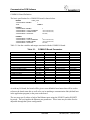
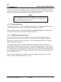
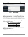
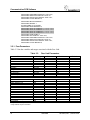
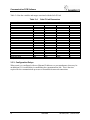
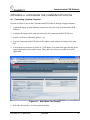
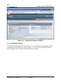
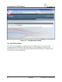
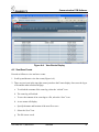
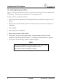
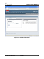
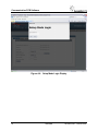
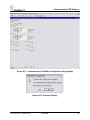
1D1.0029
Communication Printed Circuit Board
Software
Rev. 1, March 2010
SM6800D
1
Communication PCB Software
Proprietary Notice
This document and its contents are the property of Ansaldo STS USA,
Inc. (formerly known as Union Switch & Signal Inc., and hereinafter
referred to as "ASTS USA"). This document is furnished to you on the
following conditions: 1.) That no proprietary or intellectual property
right or interest of ASTS USA is given or waived in supplying this
document and its contents to you; and, 2.) That this document and its
contents are not to be used or treated in any manner inconsistent with
the rights of ASTS USA, or to its detriment, and are not to be copied,
reproduced, disclosed or transferred to others, or improperly disposed
of without the prior written consent of ASTS USA.
Copyright © 2010, Ansaldo STS USA
1000 Technology Drive, Pittsburgh, PA USA 15219-3120
645 Russell Street, Batesburg, SC 29006
www.ansaldo-sts.com/usa
All rights reserved.
Revision History
REV.
1
2
ISSUE DATE
March 2010
REVISION DESCRIPTION
Initial Release
SM6800D
1D1.0029, Rev. 1, March 2010
Communication PCB Software
1.
COMMUNICATION PCB SOFTWARE
To use this PCB in a MICROLOK II system, the application software must be compiled/recompiled
using a new compiler and executive software. A new diagnostic tool to match this new executive
software is also required.
The part number for Communication Software is N451232-2165.
Refer to ASTS USA service manual SM 6800D for information regarding application
programming and the diagnostic tool.
2.
INTRODUCTION
Version 3.0 and higher of the MICROLOK II Certified Executive (MLKII-CC) (ASTS USA part
number N17066403) contains enhancements to the MICROLOK II system to allow direct
connections to Ethernet based networks and a new network protocol.
This document contains basic information relating to the specification and operation of the newly
implemented features.
This document contains information relating to the new features of version 3.x of the MICROLOK
II Certified Executive and does not contain information relating to existing features. Refer to
ASTS USA service manual SM6800D for Microlok II Programming information.
3.
EXECUTIVE VERSION MLKII-CC 3.0
Executive Version MLKII-CC 3.0 and higher adds a new I/O board for Ethernet connectivity, a
new network protocol (Safe-P) for communications with the ASTS-F CBTC Zone Controller,
and contains a number of maintenance upgrades incorporated from the mainline MICROLOK II 8.5
executive.
3.1. COMM I/O Board
The board definition specifies the IP Address for the physical ports on the board. There are no
user input or output variables associated with the COMM I/O board.
1D1.0029, Rev. 1, March 2010
SM6800D
3
Communication PCB Software
COMM I/O Board Definition
The basic specification for a COMM I/O board is shown below.
BOARD:
board_name
<ADJUSTABLE> ENABLE:
1
TYPE:
COMM.IO
E.PORT1
<ADJUSTABLE> ENABLE:
<ADJUSTABLE> LOCAL.ADDRESS:
<ADJUSTABLE> SUBNET.MASK:
<ADJUSTABLE> GATEWAY:
1
" nnn.nnn.nnn.nnn ";
" nnn.nnn.nnn.nnn ";
"0.0.0.0";
E.PORT2
<ADJUSTABLE> ENABLE:
<ADJUSTABLE> LOCAL.ADDRESS:
<ADJUSTABLE> SUBNET.MASK:
<ADJUSTABLE> GATEWAY:
1
" nnn.nnn.nnn.nnn ";
" nnn.nnn.nnn.nnn";
"0.0.0.0";
Table 3-1 lists the variables and ranges associated with the COMM I/O board.
Table 3-1.
Parameter
Enable
Selective.Shutdown
.E.PORT1.ENABLED
.E.PORT1.LOCAL.ADDRESS
.E.PORT1.SUBNET.MASK
.E.PORT1.PEER.ADDRESS
.E.PORT1.GATEWAY
.E.PORT2.ENABLED
.E.PORT2.LOCAL.ADDRESS
.E.PORT2.SUBNET.MASK
.E.PORT2.PEER.ADDRESS
.E.PORT2.GATEWAY
.S.PORT1.Enabled
.S.PORT2.Enabled
.S.PORT3.Enabled
.S.PORT4.Enabled
.S.PORT5.Enabled
.S.PORT6.Enabled
COMM I/O Board Parameters
Vitality
Vital
Non-Vital
Non-Vital
Non-Vital
Non-Vital
Non-Vital
Non-Vital
Non-Vital
Non-Vital
Non-Vital
Non-Vital
Non-Vital
Non-Vital
Non-Vital
Non-Vital
Non-Vital
Non-Vital
Non-Vital
Minimum
0
0
0
0.0.0.0
0.0.0.0
0.0.0.0
0.0.0.0
0
0.0.0.0
0.0.0.0
0.0.0.0
0.0.0.0
0
0
0
0
0
0
Maximum
1
1
1
255.255.255.255
255.255.255.255
255.255.255.255
255.255.255.255
1
255.255.255.255
255.255.255.255
255.255.255.255
255.255.255.255
0
0
0
0
0
0
Default
No Default
0
No Default
No Default
No Default
0.0.0.0
0.0.0.0
No Default
No Default
No Default
0.0.0.0
0.0.0.0
0
0
0
0
0
0
As with any I/O board, the board will be given a user definable board name that will be used to
reference the board status bits as well as for use in attaching a communication link (defined later
in the application program) to the ports on the board.
The user may specify either or both of the Ethernet ports using the E.PORT1 and/or E.PORT2
keywords. The user supplies the Ethernet port parameters. These items may be either fixed or
adjustable through the system configuration.
4
SM6800D
1D1.0029, Rev. 1, March 2010
Communication PCB Software
A user may define up to six COMM I/O boards in an application. All COMM I/O boards must
appear as one of the first six I/O boards defined. Use the development tool to calculate the power
that will be required for the boards that are to be installed in the cardfile.
NOTE
The standard MICROLOK II power supply will only support two to
three COMM I/O boards. An external power supply may be
required if additional boards are used.
3.1.1.1. Ethernet Addressing
All IP Addresses must be specified in the application program as a quoted string in the format
“nnn.nnn.nnn.nnn” where nnn is a valid decimal number between 0 and 255.
When both Ethernet ports are defined, they must be on different sub-nets. Placing both ports
on the same sub-nets routes all messages through a single port.
3.1.1.2. COMM Board Diagnostic Support
The COMM I/O board has its own communications processor that provides the Ethernet
interface as well as a web based user interface. All communications utilizing a COMM I/O
board will use UDP/IP as the network protocol. The communication processor also supports
SNMP and network diagnostics.
The web based user interface, which provides status maintenance as well as facilities for
uploading new COMM board executive software, is accessed through the ports on the COMM
board. In order for a port to function properly, it must have a valid IP address. If only Port 1 on
the COMM board is used for application communications, Port 2 may be defined and disabled if
access through the web interface for that port is desired. This will provide a valid IP address for
the port for diagnostic use.
The password for uploading new COMM I/O software through the web interface is “USS”.
Figure 3-1 shows the password dialog box screen.
1D1.0029, Rev. 1, March 2010
SM6800D
5
Communication PCB Software
Figure 3-1. Password Dialog Box
3.1.2. Port Attachment
Each communication link defined in the COMM section of an application program contains a
PORT specification. Currently, the only valid values for the PORT are 1-4 and indicate one of
the serial ports on the MLKII CPU board. The port attachment is now expanded to allow the
links to attach to the Ethernet ports on the COMM I/O board as well as the serial ports on the
CPU board. The same message cannot be sent out on an Ethernet link and a serial link at the
same time. Up to two ports may be attached for each link and up to four destination IP addresses
may be defined for each station.
Table 3-2 lists the ports that can be used with the various communications links. A indicates
that the port can be used with a communication link. An absence of a indicates that the port
cannot be used with a communication link.
Table 3-2.
Communication Links and Port Availability
Communication
Protocol
Peer
Safe-P
Microlok
Genisys
Ethernet
Port
CPU Board
Serial Port
The syntax for the PORT specification has been changed from a single numeric character (1, 2,
3, or 4) to a quoted string specifying the board and port to which the link will be attached. For
the serial ports on the CPU board, this will be:
“CPU.SERIAL.x”
where x is the desired port on the CPU board (1, 2, 3, or 4).
6
SM6800D
1D1.0029, Rev. 1, March 2010
Communication PCB Software
For attaching to an Ethernet port, the syntax will be:
PORT: “boardname.E.PORT.x”
where boardname is the user-defined name of the COMM I/O board and x is the desired Ethernet
port on the COMM I/O board (1 or 2).
This specifies the attachment of the physical port to the communications link and is part of the
link parameters. A single communication link (PEER or Safe-P protocols only) may specify one
port for normal communications or two ports for redundant networks. In the case of redundant
networks, the same messages will be sent over both networks. The receiving unit will receive
two identical copies of the same message. The first message received will be processed normally
and the second identical message will be discarded as a duplicate. The syntax for the second port
attachment is:
PORT2: “boardname.E.PORT.x” ;
NOTE
In the link specification (not the COMM I/O board specification),
Port2 is only valid in cases where two ports are attached. If only
one port is used, it must be PORT and the PORT2 specification is
invalid.
It is permissible to attach to only Ethernet Port 2 on the COMM
I/O board.
Once the physical port attachment has been specified, the network routing information must be
specified to identify which messages will be sent to which IP addresses. Each communication
link contains one or more station specifications that identify the data to be sent/received with the
communication partner. The PEER and Safe-P protocols identify the stations by means of the
source and destination addresses for the units. This is the information included in the message
body that is used by the receiving unit to identify messages belonging to a valid
source/destination address pair on its communication link. In order to transmit this information
over a network, the sending unit must also know the IP address of the receiving unit. In the case
of redundant networks two IP addresses must be specified, one for each physical port that is
connected to the different networks.
In addition to the redundant network possibility, the receiving unit may also be in a redundant
Normal\Stand-by (or On-Line\Off-Line) configuration where each unit will have its own IP
addresses. This leads to several possible configurations with a possibility of up to four IP
addresses and four copies of the same transmitted message.
1 IP address, one port : Communications with a single unit in a standard network
configuration
1D1.0029, Rev. 1, March 2010
SM6800D
7
Communication PCB Software
2 IP addresses, two ports: Communications with a single unit in a redundant network
configuration
2 IP addresses, one port: Communications with redundant units in a standard network
configuration
4 IP addresses, two ports: Communications with redundant units in a redundant network
configuration
The IP address information is included with the rest of the station information as a quoted string
that represents a valid IP address.
<ADJUSTABLE> PEER.IP.ADDRESS.<port>.<unit>: " nnn.nnn.nnn.nnn ";
In the above example, <port> will be 1 or 2 identifying the physical port on the COMM I/O
board and <unit> will be A or B identifying the different units in a redundant configuration. For
the above configurations:
1 IP address, one port: Communications with a single unit in a standard network
configuration. The link specification will attach one port.
o
PEER.IP.ADDRESS.1.A: “nnn.nnn.nnn.nnn”
2 IP addresses, two ports: Communications with a single unit in a redundant network
configuration. The link specification will attach both ports.
o
o
PEER.IP.ADDRESS.1.A: “nnn.nnn.nnn.nnn”
PEER.IP.ADDRESS.2.A: “nnn.nnn.nnn.nnn”
2 IP addresses, one port: Communications with a redundant unit in a standard network
configuration. The link specification will attach one port.
o
o
PEER.IP.ADDRESS.1.A: “nnn.nnn.nnn.nnn”
PEER.IP.ADDRESS.1.B: “nnn.nnn.nnn.nnn”
4 IP addresses, two ports: Communications with a redundant unit in a redundant network
configuration.
o
o
o
o
PEER.IP.ADDRESS.1.A: “nnn.nnn.nnn.nnn”
PEER.IP.ADDRESS.1.B: “nnn.nnn.nnn.nnn”
PEER.IP.ADDRESS.2.A: “nnn.nnn.nnn.nnn”
PEER.IP.ADDRESS.2.B: “nnn.nnn.nnn.nnn”
When attaching to an Ethernet port on the COMM I/O board, none of the physical port
configuration items associated with the serial links are required. Baud rate, key-on and key-off
delays and other link related items are not applicable for Ethernet communications. The only
link parameters that are used are the protocol specification and port assignment. Likewise, the
Ethernet specifications in the stations have no meaning for the serial links. In order to minimize
the impact of the multiple link attachment options, the link and station configurations will
maintain values for all possible configuration options. The values not used for a particular link
attachment will be disregarded.
8
SM6800D
1D1.0029, Rev. 1, March 2010
Communication PCB Software
3.1.3. COMM I/O Board Status Variables
The COMM I/O board does not provide any user defined application variables but there are a
number of system variables associated with the board.
<board_name>.Enabled – Board enable bit. Set if the board is enabled in the system
configuration, clear otherwise
<board_name>.Selective.Shutdown – Not used
<board_name>.E.PORT1.ENABLED – Port enable bit for Ethernet port 1. Set if the port is
enabled in the system configuration, clear otherwise
<board_name>.E.PORT2.ENABLED – Port enable bit for Ethernet port 2. Set if the port is
enabled in the system configuration, clear otherwise
3.1.4. Power-Up Delay
When a unit is first powered up, it can take up to one minute for the communications processor
on the COMM I/O board to complete its boot-up processing. This will present to the MLKII-CC
executive as a failed link. As soon as the communication processor has completed its boot-up
functions, communications will be established. This only applies to a power-up condition. After
a system reset, when power is maintained to the COMM I/O board, communications will begin
in the same time frame as the existing MLKII-CC executive revisions.
3.2. Peer Protocol
The peer-to-peer protocol allows any connected MICROLOK II unit to initiate a message sequence
to another MICROLOK II unit at any time. The protocol incorporates a delayed acknowledgement
to allow for situations where other data transmissions may occur between a message and its
acknowledgement.
This is an existing protocol that was upgraded to include IP support. The changes are highlighted
in the message below.
LINK: MII_PEER1
ADJUSTABLE ENABLE: 1
PROTOCOL: MII.PEER
ADJUSTABLE PORT: "VITAL_COMMIO_01.E.PORT1";
ADJUSTABLE PORT2:"VITAL_COMMIO_01.E.PORT2";
ADJUSTABLE MII.ADDRESS: 1
ADJUSTABLE ENABLE: 1
STATION.NAME: V_STATION1;
ADJUSTABLE PEER.ADDRESS: 2;
ADJUSTABLE PEER.IP.ADDRESS.1.A: "nnn.nn.n.nnn";
ADJUSTABLE PEER.IP.ADDRESS.1.B: "nnn.nn.n.nnn";
ADJUSTABLE PEER.IP.ADDRESS.2.A: "nnn.nn.n.nnn";
ADJUSTABLE PEER.IP.ADDRESS.2.B: "nnn.nn.n.nnn";
ADJUSTABLE TIME.STAMP: 0;
ADJUSTABLE ACK.TIMEOUT: 1200: msec;
1D1.0029, Rev. 1, March 2010
SM6800D
9
Communication PCB Software
ADJUSTABLE HEARTBEAT.INTERVAL: 1200: msec;
ADJUSTABLE INDICATION.UPDATE.CYCLE: 50;
ADJUSTABLE STALE.DATA.TIMEOUT: 3000: msec;
ADJUSTABLE CLOCK.MASTER: 0;
ADJUSTABLE MII.NV.ADDRESS: 3
ADJUSTABLE ENABLE: 1
STATION.NAME: NV_STATION1;
ADJUSTABLE PEER.ADDRESS: 4;
ADJUSTABLE PEER.IP.ADDRESS.1.A: "nnn.nn.n.nnn";
ADJUSTABLE PEER.IP.ADDRESS.1.B: "nnn.nn.n.nnn";
ADJUSTABLE PEER.IP.ADDRESS.2.A: "nnn.nn.n.nnn";
ADJUSTABLE PEER.IP.ADDRESS.2.B: "nnn.nn.n.nnn";
ADJUSTABLE TIME.STAMP: 0;
ADJUSTABLE ACK.TIMEOUT: 1200: msec;
ADJUSTABLE HEARTBEAT.INTERVAL: 1200: msec;
ADJUSTABLE INDICATION.UPDATE.CYCLE: 50;
ADJUSTABLE STALE.DATA.TIMEOUT: 3000: msec;
ADJUSTABLE CLOCK.MASTER: 0;
3.2.1. Peer Parameters
Table 3-3 lists the variables and ranges associated with the Peer Link.
Table 3-3.
Parameter
Peer Link Parameters
Vitality
Minimum
Link Parameters
Maximum
Default
Enable
Point.Point *
Port
Port2 **
Baud *
Stop Bits *
Parity *
Key.On.Delay *
Key.Off.Delay *
Grant.Delay *
IP.Port **
Vital
Vital
Vital
Vital
Non-Vital
Non-Vital
Non-Vital
Non-Vital
Non-Vital
Non-Vital
Non-Vital
0
0
Available Ports
Available Ports
300
1
0
0
0
10
1
1
1
Available Ports
Available Ports
38400
2
255
900
900
10000
65535
0
0
No Default
No Default
19200
1
1
0
0
1
1
Enable
Time.Stamp
Station.Address.Type
Address
Peer.Address
Peer.IP.Address.1.A **
Peer.IP.Address.1.B **
Peer.IP.Address.2.A **
Peer.IP.Address.2.B **
Stale.Data.Timeout
Ack.Timeout
Heartbeat.Interval
Indication.Update.Cycle
Clock.Master
* Only valid for serial port connection.
**Only valid for IP port connection.
Vital
Vital
Vital
Vital
Vital
Non-Vital
Non-Vital
Non-Vital
Non-Vital
Non-Vital
Vital
Vital
Vital
Vital
0
0
0
0
0
0.0.0.0
0.0.0.0
0.0.0.0
0.0.0.0
500
50
100
1
0
1
1
1
10
10
255.255.255.255
255.255.255.255
255.255.255.255
255.255.255.255
600000
600000
600000
100
1
0
1
0
0
0
0.0.0.0
0.0.0.0
0.0.0.0
0.0.0.0
1000
1000
1000
10
0
10
Station Parameters
SM6800D
1D1.0029, Rev. 1, March 2010
Communication PCB Software
3.3. Safe-P Protocol
The Safe-P protocol allows a MICROLOK II system to communicate directly with other types of
equipment that utilize this protocol. It is primarily intended for use in CBTC systems where
MICROLOK II is acting as an Object Controller interfacing to ASTS-F Zone Controller.
3.3.1. Safe-P Protocol Specification
The syntax for the Safe-P protocol is similar to the PEER syntax in that there are link parameters
and station parameters. The Safe-P protocol may only be attached to an Ethernet port on a
COMM I/O board.
LINK: SAFE_P_1
<ADJUSTABLE> ENABLE: 1
PROTOCOL: MII.SAFEP
ADJUSTABLE PORT: "<board_name>.E.PORT1";
ADJUSTABLE PORT2: "<board_name>.E.PORT2";
ADJUSTABLE SAFEP.ADDRESS: 1
ADJUSTABLE ENABLE: 1
STATION.NAME: MP_88.1;
ADJUSTABLE SAFEP.PEER.ADDRESS: 2;
ADJUSTABLE PEER.IP.ADDRESS.1.A: "nnn.nnn.nnn.nnn";
ADJUSTABLE PEER.IP.ADDRESS.1.B: " nnn.nnn.nnn.nnn ";
ADJUSTABLE PEER.IP.ADDRESS.2.A: " nnn.nnn.nnn.nnn ";
ADJUSTABLE PEER.IP.ADDRESS.2.B: " nnn.nnn.nnn.nnn ";
ADJUSTABLE BROADCAST.INTERVAL: 300:MSEC;
ADJUSTABLE STALE.DATA.TIMEOUT: 2000:MSEC;
3.3.2. Safe-P Parameters
Only one new configuration parameter has been added for the Safe-P protocol. The
BROADCAST.INTERVAL specifies the rate at which messages are sent. This parameter has a
valid range of 300 ms – 10,000 ms with a default value of 300 ms.
1D1.0029, Rev. 1, March 2010
SM6800D
11
Communication PCB Software
Table 3-4 lists the variables and ranges associated with the Safe-P Link.
Table 3-4.
Parameter
Enabled
Point.Point *
Port
Port2
Baud*
Stop Bits*
Parity*
Key.On.Delay*
Key.Off.Delay*
IP.Port
Enable
SafeP.Address
SafeP.Peer.Address
Peer.IP.Address.1.A
Peer.IP.Address.1.B
Peer.IP.Address.2.A
Peer.IP.Address.2.B
Stale.Data.Timeout
Broadcast.Interval
* Only valid for serial port connection.
Safe-P Link Parameters
Vitality
Minimum
Link Parameters
Vital
Non-Vital
Vital
Vital
Non-Vital
Non-Vital
Non-Vital
Non-Vital
Non-Vital
Non-Vital
0
0
Available Ports
Available Ports
300
1
0
8
8
1
Station Parameters
Vital
0
Vital
1
Vital
1
Non-Vital
0.0.0.0
Non-Vital
0.0.0.0
Non-Vital
0.0.0.0
Non-Vital
0.0.0.0
Vital
900
Vital
300
Not used for Safe-P links.
Maximum
Default
1
1
Available Ports
Available Ports
38400
2
255
900
900
65535
0
0
No Default
No Default
19200
1
1
1
1
1
1
65535
65535
255.255.255.255
255.255.255.255
255.255.255.255
255.255.255.255
20000
10000
0
1
1
0.0.0.0
0.0.0.0
0.0.0.0
0.0.0.0
2000
10
3.3.3. Configuration Delays
When a unit is re-configured with new Ethernet IP addresses or port attachments, there may be
an additional 5-10 second delay in establishing the communications link. This is the time
required for the communications processor to reestablish its network connections.
12
SM6800D
1D1.0029, Rev. 1, March 2010
Communication PCB Software
4.
PROGRAM EXAMPLE
LOCAL
BOARD: COMM_IO_1
ENABLE: 1
TYPE: COMM.IO
E.PORT1
ENABLE: 1
LOCAL.ADDRESS: "172.25.1.100";
SUBNET.MASK: "255.255.255.0
GATEWAY: "0.0.0.0";
E.PORT2
ENABLE: 1
LOCAL.ADDRESS: "172.25.2.100";
SUBNET.MASK: "255.255.255.0";
GATEWAY: "0.0.0.0";
COMM
LINK: MII_PEER
ENABLE: 1
PROTOCOL: MII.PEER
PORT: "COMM_IO_1.E.PORT1"; /* Comm board 1- Ethernet port 1 */
PORT2: "COMM_IO_1.E.PORT2"; /* Comm board 1 -Ethernet port 2 */
MII.ADDRESS: 1
ENABLE: 1
STATION.NAME: MP_88.0;
PEER.ADDRESS: 2;
PEER.IP.ADDRESS.1.A: "172.25.1.102";
PEER.IP.ADDRESS.1.B: "172.25.1.112";
PEER.IP.ADDRESS.2.A: "172.25.2.102";
PEER.IP.ADDRESS.2.B: "172.25.2.112";
TIME.STAMP: 1;
ACK.TIMEOUT: 1000:MSEC;
HEARTBEAT.INTERVAL: 1000:MSEC;
INDICATION.UPDATE.CYCLE: 1;
STALE.DATA.TIMEOUT: 3000:MSEC;
OUTPUT:
MII.O2.000, MII.O2.001, MII.O2.002, MII.O2.003,
MII.O2.004, MII.O2.005, MII.O2.006, MII.O2.007;
INPUT:
MII.I2.000, MII.I2.001, MII.I2.002, MII.I2.003,
MII.I2.004, MII.I2.005, MII.I2.006, MII.I2.007;
MII.ADDRESS: 3
ENABLE: 1
STATION.NAME: MP_88.3;
PEER.ADDRESS: 4;
PEER.IP.ADDRESS.1.A: "172.25.1.102";
PEER.IP.ADDRESS.1.B: "172.25.1.114";
PEER.IP.ADDRESS.2.A: "172.25.2.102";
PEER.IP.ADDRESS.2.B: "172.25.2.114";
ACK.TIMEOUT: 1000:MSEC;
HEARTBEAT.INTERVAL: 1000:MSEC;
INDICATION.UPDATE.CYCLE: 1;
STALE.DATA.TIMEOUT: 3000:MSEC;
OUTPUT:
MII.O4.000, MII.O4.001, MII.O4.002, MII.O4.003,
1D1.0029, Rev. 1, March 2010
SM6800D
13
Communication PCB Software
INPUT:
14
MII.O4.004, MII.O4.005, MII.O4.006, MII.O4.007;
MII.I4.000, MII.I4.001, MII.I4.002, MII.I4.003,
MII.I4.004, MII.I4.005, MII.I4.006, MII.I4.007;
SM6800D
1D1.0029, Rev. 1, March 2010
Communication PCB Software
APPENDIX-A. ACCESSING THE COMMUNICATION PCB
A.1 Connecting a Laptop Computer
Proceed as follows to access the Communication PCB Software through a laptop computer:
1. Connect the laptop to either Ethernet connector on the back of the Communication PCB
Software.
2. Configure the laptop on the same sub-network as the Communication PCB Software.
3. Open a web browser (Internet Explorer, e.g.).
4. Type the Communication PCB Software IP Address in the address bar and press the enter
key.
5. A main menu screen shown in Figure A-1 will display. The main menu page has tabs in the
upper right header section of the screen. These tabs are used to access other areas of the
application.
Figure A-1. Main Menu Tabs Display
6. Select the desired tab to view the particular display.
1D1.0029, Rev. 1, March 2010
SM6800D
15
Communication PCB Software
NOTE
The Setup function is a privileged mode. Use extreme caution
when working in the Setup mode.
View Global Parameters (see Section A.2)
View Message (see Section A.3)
View Events (see Section A.4)
A.2 View Global Parameters
The Global Parameters tab displays SNMP and Global parameters as shown in Figure A-2.
The following SNMP parameters are displayed:
Community Name Read Only
System Name
System Contact
Enable Traps
Target I.P. Address for Traps
Inform Enable/Disable
Inform Retries
Inform Retry Delay
The following Global parameters are displayed:
Product ID
Product Name
Location
16
SM6800D
1D1.0029, Rev. 1, March 2010
Communication PCB Software
Figure A-2. View Global Parameters Display
A.3 View Message Display
The Message View tab displays instructions on how to view the data traffic passing through the
Communication PCB Software as shown in Figure A-3. This involves using HyperTerminal.
Message logging can be enabled or disabled by using this display.
1D1.0029, Rev. 1, March 2010
SM6800D
17
Communication PCB Software
Figure A-3. View Messages Display
A.4 View Events Display
The Event View tab displays the application events contained in the event log file on the
Communication PCB Software as shown in Figure A-4. The timestamp, event code, and
description for every event received from the Communication PCB Software is displayed. The
most recent 100 events are displayed.
18
SM6800D
1D1.0029, Rev. 1, March 2010
Communication PCB Software
Figure A-4. View Events Display
A.5 View/Save Events
Proceed as follows to view and save events:
1. Scroll up and down to view the events (Figure A-4).
2. There are two icons in the top right corner just above the Events display. One saves the log to
a file and the other refreshes the page.
a. To refresh the contents of the event log, select the “refresh” icon.
b. The event log will refresh.
c. To save the contents of an event log to a file, select the “Save” icon.
d. A save menu will display
e. Specify the name and location of the new file to save.
f. Select the “Save” box.
g. The file is now saved.
1D1.0029, Rev. 1, March 2010
SM6800D
19
Communication PCB Software
A.6 Uploading Operating Software
Figure A-5 shows the tab that allows the user to upload all necessary files to the Communication
PCB Software. The software is maintained in a *.tar compression file.
Proceed as follows to upload the software:
1. Select Setup from the main menu. The Setup Mode Login screen shown in Figure A-6 will
display.
2. Enter the password. The default password is "USS". The Setup screen shown in Figure A-5
will display.
3. Select Upload.
4. Specify file type to be uploaded.
5. Browse to the location of the desired file.
6. Click upload, this process take approximately 5 minutes depending on the size of the
application. The message shown in Figure A-7 will display while the upload is in progress.
7. Cycle power after the message "upload is complete" appears.
NOTE
The .tar file contains all necessary images for the u-boot, linux,
COMMUNICATION PCB Application and the FPGA.
Do not power-off the board during an upload.
20
SM6800D
1D1.0029, Rev. 1, March 2010
Communication PCB Software
Figure A-5. Software Update Display
1D1.0029, Rev. 1, March 2010
SM6800D
21
Communication PCB Software
Figure A-6. Setup Mode Login Display
22
SM6800D
1D1.0029, Rev. 1, March 2010
Communication PCB Software
Figure A-7. Upload in Progress Display
A.7 Configuring the Communication PCB
Proceed as follows to access the Communication PCB configuration options:
1. Click on the System Configuration button on the Maintenance Tool main menu. The system
will display an options dialog box that lets you specify whether you wish to view or change
configuration settings.
2. Determine whether you want to examine the configuration settings, modify the non-vital
settings only, or modify all settings. If you opt to examine the settings, the system will permit
no changes to the displayed configuration parameters. The default selection on the form is to
modify vital and non-vital settings. Click on the appropriate option.
3. If you selected an option to modify any settings in Step 2, a password dialog box will appear.
The default password is “microlokii”. If you selected to examine the configuration settings
step 2, you do not have to enter a password.
1D1.0029, Rev. 1, March 2010
SM6800D
23
Communication PCB Software
4. Press the RESET pushbutton on the front panel of the Microlok II CPU board and then click
on the OK button in the dialog box.
5. The System Configuration display will appear as seen in Figure A-8. This display provides
direct access to all of the Microlok II configuration options for this unit.
Figure A-8. System Configuration Display
6. Click on the Comm.IO board button.
7. The Comm.IO board main configuration page will appear as in Figure A-9. The options for
the Comm.IO board will appear. The valid ranges for the configuration items can be found
in Table 3-1.
8. When the modifications are completed, click the "Done" button.
9. Any changes will be displayed in a popup window as shown in Figure A-10.
10. When you are done configuring the Microlok II unit, click on the “Done with Configuration”
button. The updated values will be written to the Microlok II unit and the unit will reset.
The Development System will return to the main menu.
24
SM6800D
1D1.0029, Rev. 1, March 2010
Communication PCB Software
Figure A-9. Communication PCB Main Configuration Page Display
Figure A-10. Changes Display
1D1.0029, Rev. 1, March 2010
SM6800D
25
Communication PCB Software
End of Module
26
SM6800D
1D1.0029, Rev. 1, March 2010