1
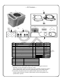
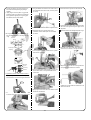
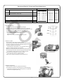
Instruction Manual for
DOHC 4-VALVE HEAD PISTON / CYLINDER KIT
CO
Item No. :01―04―6124H
Fits:
:12V Monkey and Gorilla
Frame Nos :Z50J-2000001 ∼
:AB27-1000001 ∼
Thank you for purchasing one of our TAKEGAWA’s products.
These piston and cylinder kits are for exclusive use in a motorcycle equipped with a TAKEGAWA’s DOHC 4-valve head. Please strictly follow the following
instructions in installing and using the kit.
● Please note that, in some cases, the illustrations and photos may vary from the actual hardware.
Please read the following before starting the installation
Serial No.
stamped here.
NOTE
◎The old type DOHC Head Kit of Item Nos. (01-03-6002, 01-03-6003, or 01-03-6004)
cannot be used with this product.
◎The product with a serial No. from (00001 to 00474) cannot be used with this kit.
PY
о We do not take any responsibility for any accident or damage whatsoever arising from the use of the kit not in conformity with the instructions in the manual.
о These products are for exclusive in a motorcycle equipped a TAKAGEWA’s DOHC 4-valve head.
о In case these kits are to be used in a stock crankcase, the crankcase needs to be processed in the section where a sleeve is to be inserted. Consult a
technically-reliable shop specialized in internal combustion products or motorcycles about the processing.
оProcessing of a stock crankcase requires detachment and installation of the engine and separation of the crankcase. Please install the products correctly,
referring to a HONDA’s genuine service manual for the above-mentioned compatible motorcycles. And the assembly and installation require gaskets, etc.,
which please purchase separately.
о These kits are compatible only with motorcycles equipped with a stock or TAKEGAWA-made CDI.
о Please be informed that we shall be held harmless against any claim against us whatsoever arising out of use of the products in racing and the like.
The following show the envisioned possibility of injuries to human bodies and property damage as a result of disregarding the
CAUTION following cautions.
○These kits are intended for closed course competition purposes only. So, it is prohibited to drive your motorcycle on a public road after the installation
of these kits. Drive your motorcycle at a legal speed, abiding by the laws.
○ Make sure before the installation that the engine and muffler are cool. (Otherwise, you will burn yourself.)
○ Do the installation with right tools. (Otherwise, breakage of parts or injuries to yourself may take place.)
○ As some products and frames have sharp edges or protruding portions, please work with your hands protected. (Otherwise, you will suffer injuries.)
The following show the envisioned possibility of human death or serious injuries to human bodies as a result of disregarding the
WARNING following cautions.
○ Those who are technically unskilled or inexperienced are required not to do the work.
(Improper installation because of insufficient skill and knowledge could lead to parts breakage and subsequently to accidents.)
○ Always use new piston pin circlips, gaskets and packings. The worn or damaged parts may break the parts, leading to accidents.
○ Before doing work, make sure your motorcycle is secure on level ground for safety’s sake.
(Otherwise, your motorcycle could overturn and injure you while you are working.) ○ If you find damaged parts when checking and performing maintenance of your motorcycle, do not use these parts any longer, and replace them with
new ones. (The continued use of these damaged parts as they are could lead to accidents.)
○ Always start the engine in a well-ventilated place, and do not turn on the engine in an airtight place.
(Otherwise, you will suffer from carbon monoxide poisoning.)
○ Before riding, always check every section for slack in parts like screws. If you find slack ones, screw them securely up to the specified torque. (Otherwise, improper tightening may cause parts to come off.)
○ When you notice something abnormal with your motorcycle while riding down a road, stop riding immediately and park your motorcyle in a safe place.
(Otherwise, the abnormality could lead to accidents.)
○As gasoline is highly flammable, never place it close to fire. Make sure that nothing flammable is near the gasoline. Since vaporized accumulation of gasoline is at high risk of explosion, work in a well-ventilated place. (Otherwise, it may cause a fire.)
○ Check or carry out maintenance of your motorcycle correctly according to the procedures in the instruction manual or service manual.
(Improper checking or maintenance could lead to accidents.) ○ Never use any other parts than those specified by us. (The use of the unspecified parts may lead to parts breakage and consequent accidents)
○ Always use a torque wrench to screw bolts and nuts tight and securely to the specified torque.
(Otherwise, these parts may get damaged or fall off, resulting in accidents.)
○ Since vaporized accumulation of gasoline is at high risk of explosion, work in a well-ventilated place. (Otherwise, it may cause an explosion.)
○ Fuel must be high-octane gasoline. (Otherwise, troubles such as engine knocking may cause accidents.)
◎ Please be informed that, mainly because of improvement in performance, design changes, and cost increase, the product specifications and prices
are subject to change without prior notice.
◎ Please be informed that we shall be held harmless against any claim against us whatsoever arising out of use of the products in racing and the like.
◎ This manual should be retained for future reference.
-A1-
Oct./04/’
07
∼ Kit Contents ∼
1
A
CO
6
7
8
2
4
5
D
C
5
9
PY
3
10
B
No.
1
2
3
4
5
6
7
8
9
10
Part Name
Aluminum Cylinder
Piston
Piston Ring Set (Top, 2nd, Oil)
Piston Pin
Piston Pin Circlips, 13x1
Cylinder Head Gasket
Cylinder Gasket
Rubber Packings (Black)
Dowel Pins, 8x14
Dowel Pins, 8x12
Qty
1
1
1 set
1
2
1
1
2
2
2
Repair Part No.
01-01-0251H
13105-D4H-T20L
01-15-015
13111-GEF-T01
00-01-0003
12251-GFL-T20
12191-GW8-T01
00-01-0066
No.
A
B
C
D
Repair Part No.
Part Name
01-13-8003V
Gasket kit
01-02-6018
Piston kit
00-01-0003
Piston pin circlip set(6 pieces)
00-01-0090
Dowel Pin set
In packs of
1
1
1
1
6
1
1
2
※Please note that in ordering repair parts, be sure to quote the Repair Part Item No. Otherwise, we may not be able to accept your orders.
There are some parts, however, for which we are not in a position to accept your order in
just the quantity to be used. In this case, please take them in the quantity packed.
※Composition and gasket shapes of the gasket kit differ depending on the kind of cylinder head and cylinder. Therefore, please always use the special gasket for the
cylinder head or cylinder.
-A2-
Oct./04/’
07
Boring Process to the Crankcase
◇ In case you get your crankcase bored outside our factory.
CO
○ Joining together the cylinder and the boring-processed section of the crankcase, process the crankcase little by little until the size measures φ 56.8 ∼
φ 57.0 mm with a crankcase gasket being squeezed.
※Processing of the crankcase will thin the thinkness of the wall adjoining dowel pin holes. So the durability of the crankcase will be reduced, resulting in the
possible damage of the crankcase in some cases, which please take note.
24.5±0.
1
Dowel Pin Hole
26±0.1 22.5±0.
1
24±0.1
φ
∼ 56
φ5 .8
7.
0
Gasket
Dowel Pin Hole
PY
27±0.2
Caution
○ Since crankcase boring thins the wall thickness and reduces hardness, be careful in tightening stud bolts. ○Please take note that in some cases the crankcase may get damaged during use. Furthermore, please be informed that we shall assume no liability to users
for compensation or damages whatsoever of any kind.
Co.,Ltd.
3-5-16 Nishikiorihigashi Tondabayashi Osaka Japan
TEL : 81-721-25-1357 FAX : 81-721-24-5059
URL : http://www.takegawa.co.jp
-A3-
Oct./04/’
07
∼ Installation Procedures ∼
Note
: Always use a torque wrench to screw bolts and nuts tight and securely to the specified torque.
Warning : Those who are technically unskilled or inexperienced are required not to do the work.
◇ About the use of inner rotar CDI:
CO
Usable
Not Usable
(Compatible with this kind of base plate)
(Not compatible with this kind of base plate)
Only one tap
Tap for 88 cc
Tap for 106cc
◇ Installation of this kit requires engine removal and crankcase disassembly. Do the work correctly, strictly following a HONDA genuine service manual for
your vehicle.
○ Referring to the service manual, detach the engine from the frame and disassemble it.
○ Boring of the crankcase is required.
・Measure the misalignment at two points at the
big end of the con’rod at right angles to the shaft as shown in the figure on the right.
Please proces the boring of the crankcase
referring to the attached sheet.
∴ If larger than 0.05mm, replace it.
о Check every part.
Caution: Infallibly inspect every part and check
consumable parts for damage and wear.
What to check:
・Measure the internal diameter at the small end
of the con’rod.
∴ If larger than 13.03 mm, replace it.
・Measure the clearance at the big end of the
con’rod in the axial direction.
∴ If larger than 0.6mm, replace it.
・Measure the deflection of the crank shaft.
∴ If larger than 0.10 mm, replace it.
PY
Y
X
26mm
30mm
o Assemble the crankcase referring to the
instruction manual or the service manual for the Crankshaft Kit.
о Attach a piston pin clip to either of the piston
pin grooves.
・Measure the misalignment on the journal
bearing of the crank shaft.
∴ Shaft direction:If larger than 0.10 mm,
replace it.
Bearing direction: If larger than 0.05 mm, replace it.
NEW
оAttach the piston pin circlip so the ring end gap
does not meet with the notch on the piston pin
hole, and it should be either on the top or at the
bottom of the hole as illustrated in the figure
below.
Ring-end gap
-B1-
Oct./04/’
07
оAir-blow the piston rings and the piston pin, and check for their jamming any foreign
material.
о Apply engine oil to the piston ring grooves. Install the piston rings with the printed side
facing upward, aligning the ring-end gaps.
For details, see the photo below.
о Plug the sleeve hole and the cam chain hole on
CO
NEW
о Remove the waste cloth used to clog the holes.
※A ring with a silver-coated side is a top ring. Do not make mistakes in choosing the right rings.
оFit the aluminum cylinder into the stud bolt.
the crankcase with a clean cloth, and fix a piston
pin circlip.
о Degrease well the cylinder base of the
crankcase, and fix dowel pins onto the dowel pin holes.
оCompressing the piston rings, install the cylider
with care not to get the ring-end gaps out of
alignment.
Note: Be careful not to damage the piston rings.
Top ring
120°
120°
120°
Second ring
Expander
Side rails
60°
NEW
Second ring
Side rails
Piston
Expander
Pay attention to the cross section as well!!
о Apply molybdenum solution to the piston pin
and the holes on the connecting rod small end.
PY
о Fix a supplied cylinder gasket into the cylinder
base of the crankcase.
60°
Silver coated
Top ring
оPlace the cam chain guide roller inside the cam chains, as shown in the figure below.
оTemporarily tighten the cam chain guide roller
and cylinder side bolt for the moment.
о Fix a supplied new rubber packing (black) onto
the oil-return hole on the cylinder base of the crankcase.
MO-OIL
о Install the cylinder head with reference to its
NEW
instruction manual.
оApply engine oil to the entire inner surface of the
aluminum cylinder bore.
о Install the piston onto the connecting rod with
an arrow on the piston facing the exhaust side.
-B2-
Oct./04/’
07
Benchmark Data for Cylinder and Piston Maintenance
Description
Cylinder
Piston
stock
Distortion
Internal Diameter
External Diameter (7 mm from the bottom of the skirt)
Internal Diameter of Pin Hole
External Diameter of Piston Pin
Piston Ring-End Gap
CO
Clearance between Cylinder and Piston
Clearance between Piston and Pin
Top
2nd
Oil
53.997
53.980
13.002
12.994
0.15
0.20
0.20
∼
∼
∼
∼
∼
∼
∼
54.020 mm
54.000 mm
13.008 mm
13.000 mm
0.38 mm
0.45 mm
0.70 mm
0.002 ∼ 0.014 mm
○ Inspection of Cylinder:
・Check the inside of the cylinder for wear and damage.
・Measure and take note of the internal diameters of the cylinder at 6 positions: in the direction of piston pins and at the right angle to it (in the
X-Y direction) each at upper, middle and lower parts.
PY
Treat the measured largest value as its internal diameter. ∴If the diameter is larger than 54.05 mm,
replace the cylinder.
Figure out the clearance between cylinder and piston.
Service Limit
0.05 mm
52.05 mm
53.97 mm
13.03 mm
12.98 mm
0.50 mm
0.50 mm
0.90 mm
0.12 mm
0.05 mm
IN
Top
Y
Remarks
Replace
Replace
Replace
Replace
Replace
Replace
Replace
Replace
Replace
Replace
EX
X
Middle
Bottom
○ Inspection of Piston:
・Clear the piston of the remaining carbon residue. ・Fit a piston ring into the piston, and measure the clearance between
the piston ring and ring groove with a thickness gauge, with a piston
ring being inserted into the ring groove. ∴ If the clearance is larger than 0.17 mm, replace the piston.
・Check the outside of the piston for the damage.
・Measure the external diameter of the piston at the specified place at
the bottom edge of the piston skirt at the right angle to the piston holes.
∴If the diameter is smaller than 53.97 mm, replace the piston.
・Measure the internal diameter of the piston pin hole.
∴ If it is larger than 13.03 mm, replace the piston. ・Figure out the clearance between the piston and piston pin. ○Inspection of Piston Ring:
・Insert each piston ring into the cylinder from the bottom.
And measure the clearance of the end gap with a thickness gauge.
∴ If the clerance is larger than 0.5 mm at top and 2nd, or larger than
0.9 mm at oil, change the piston ring.
-C1-
Oct./04/’
07