1
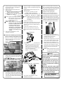
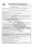
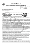
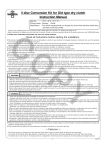
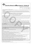
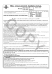
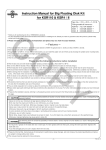
Instruction Manual for Super Oil Cooler Kit
Item No. :09−07−2212 (4-fin)
CO
:09−07−2213 (3-fin)
Fitting models and frame Nos:
Ape50
:AC16-1000001∼
Ape50 (FI)
:AC16-1600001∼
Ape50 (FI Type-D) :AC18-1000001∼
Ape100
:HC07-1000001∼
Ape100 Type-D
:HC13-1000001∼
(But limited to bikes equipped with our TAKEGAWA-made
Bore Up Cylinder or Die-Cast lutch Cover.)
・Thank you for purchasing one of our TAKEGAWA-made products. Please strictly follow the following instructions in installing and using the kit.
・Before installing the kit, please be sure to check the kit contents. Should you have any questions about the kit, please contact your local motorcycle dealer.
◎ Please note that the descriptions in this manual like illustrations and photos may differ from the actual hardware.
Read all instructions first before starting the installation
◎ We do not take any responsibility for any accident or damage whatsoever arising from the use of the kit not in conformity with the instructions in the manual.
◎ We shall be held free from any kind of warranty whatsoever of products other than this product if the glitch takes place on the other products than this
one after the installation and use of this product.
◎ You are kindly requested not to contact us about the combination of our products with other manufacturers'.
◎Please note that this kit is designed for exclusive use in the above-mentioned fitting models and frame numbers only and that it cannot be mounted on any
other models.
◎ Installation of this kit requires detachment and reinstallation of a tank and other hardware. We would recommend you to refer to the relative HONDA service manual to do the correct work.
◎ You can install this Kit onto our bore-up cylinder (with an oil line outlet hole on the right side of the cylinder) including a big-fin cylinder with an oil cooler
outlet, or die-cast clutch cover.
And for those motorcycles equipped with both TAKEGAWA-made Bore Up Cylinder and Die-Cast Clutch Cover, there are options for the way to drain oil.
◎ In installing this kit onto a bike with Die-Cast Magnesium Clutch Cover fixed, do the work using care not to scrach the cover or peel off the paintwork.
If the paintwork has peeled off, repaint the peeled-off portion.
PY
The following show the envisioned possibility of injuries to human bodies and property damage as a result of disregarding the following
CAUTION cautions.
・Always try to drive your motorcycle at a legal speed, abiding by the laws.
・Work only when the engine and muffler are cool. (Otherwise, you will get burned.)
・Do the installation with right tools. (Otherwise, breakage of parts or injuries to you may take place.)
・Always use a torque wrench to screw bolts and nuts tight and securely to the specified torque.
(Otherwise, these parts may get damaged or fall off, resulting in accidents.)
・As some products and frames have sharp edges or protruding portions, please work with your hands protected.
(Otherwise, you will suffer injuries.)
・Before riding, always check every hardware for slack in parts like screws. If you find slack one, screw them securely up to the specified torque.
(Otherwise, improper tightening may cause parts to come off.)
・Always use new gaskets and packings. And check those parts, to be reused, for wear and damage. If you find worn or damaged parts, replace
them with new ones.
The following show the envisioned possibility of human death or serious injuries to human bodies as a result of disregarding the following
WARNING warnings.
・Always start the engine in a well-ventilated place, and do not turn on the engine in an airtight place.
(Otherwise, you will suffer from carbon monoxide poisoning.)
・When you notice something abnormal with your motorcycle while riding, immediately stop riding and park your motorcyle in a safe place to check
what has gone wrong. (Otherwise, the abnormality could lead to accidents.)
・Before doing work, make sure your motorcycle is secure on level ground for safety's sake.
(Otherwise, your motorcycle could overturn and injure you while you are working.)
・Check or carry out maintenance of your motorcycle correctly according to the procedures in the instruction manual or service manual.
(Improper checking or maintenance could lead to accidents.)
・If you find damaged parts when checking and performing maintenance of your motorcycle, do not use these parts any longer, and replace them with new ones. (The continued use of these damaged parts as they are could lead to accidents.)
・As gasoline is highly flammable, never place it close to fire. Make sure that nothing flammable is near the gasoline.
Since vaporized accumulation of gasoline is at high risk of explosion, work in a well-ventilated place. (Otherwise it may cause a fire.)
◎ Please be informed that, mainly because of improvement in performance, design changes, and cost increase, the product specifications and prices are
subject to change without prior notice.
◎ This manual should be retained for future reference.
-1-
Aug./26/’
09
∼ Kit Contents ∼
1
3
2
CO
11
4
12
13
5
14
6
7
8
15 1718 19
9
20
21
10
No.
1
2
3
4
5
6
7
8
9
10
11
12
13
14
15
16
17
18
19
20
21
22
23
16
22
Part Name
Oil Cooler COMP. (3-fin)
Oil Cooler COMP. (4-fin)
Oil union, M12
Banjo bolt, M12
Banjo
Banjo bolt, M10 (the shorter one)
Banjo bolt, M10 (the longer one)
Banjo (30°)
Sealing washer, 14 mm
Sealing washer, 10 mm
Oil hose (1,300 mm)
Hose clamp
Oil cooler stay COMP.
Cooler stay distance collar
Front cable guide
Button head screw, 6 x 10
Button head screw, 6 x 25
Flange bolt, 6 x 65
Flange nut, 6 mm
Flange U-nut, 6 mm
Plain washer, 6 mm
Insulation lock, 250 mm
Hex wrench, 4 mm
Oil hole plug
23
Qty
1
1
2
2
2
2
1
1
4
4
1
4
1
1
1
2
1
1
1
1
5
2
1
1
Repair Part Item No.
00-07-0045
00-07-0004
15620-000-T20
00-07-0034
15660-000-T01
00-07-0038
15531-GEY-T00
15661-KTK-T00
00-07-0042
00-07-0010
00-07-0012
00-00-0052
15660-GEY-T00C
15664-GCR-T00
51530-GET-T00
00-00-0092
00-00-0126
00-00-0279
00-00-0173
00-00-00081
00-00-0086
00-00-0202
In the units of
1
1
1
1
1
1
1
1
5
10
1
2
1
1
1
5
5
2
6
6
10
4
PY
19331-GEF-T00
1
※Please note that in ordering repair parts, be sure to quote the Repair Part Item No.
Otherwise, we may not be able to accept your orders.
There are some parts, however, for which we are not in a position to accept your order in just the
quantity to be used. In this case, please take them in the quantity packed.
-2-
Aug./26/’
09
Safety Precautions for Using the Oil Cooler Kit
When the oil hose is connected to the clutch cover, be sure to install a supplied oil hole plug or an extra-cost thermo unit
(Item No.02-01-5002).
Please take note that when neither of them is installed, the engine oil will not circulate through the oil cooler.
∼ Installation Instructions ∼
CO
1.Check the kit contents.
2.Do the work with right tools suitable for the
work.
6.Install the oil cooler to the cooler stay with a 6mm plain washer and 6x10 button head screw,
and tighten the screw to the specified torque.
3.
Make sure the bike is secure on a side stand.
Referring to a Honda’s genuine service manual, detach a seat, fuel tank and front fender.
※After the installation of the oil cooler, the rear
side of the standard front fender will
interfere with the oil cooler, which makes it
impossible to fix the front fender. Therefore,
cut off part of the fender so it does not
Torque: 9 N・m (0.9 kgf・m)
interfere with the oil cooler.
4.Fit a cooler stay distance collar into a hole in
the lower part of the front fuel tank pad.
2.Into the M10 banjo bolt (the longer one), fit a
sealing washer, banjo and sealing washer in
this order. And loosely fasten it for now to the upper oil line on the cylinder.
3.Into the M10 banjo bolt (the shorter one), fit a
sealing washer, banjo and sealing washer in
this order. And loosely fasten it for now to the lower oil line on the cylinder.
CAUTION: At this point, check that the sealing
washers are right at the center
of the banjos. Tightening of these
washers, being out of place, will
cause oil to leak.
PY
being careful not to get the sealing washer on
the oil cooler get out of place from the recessed
portion on the hexagonal oil-cooler header.
※The tightening of the union bolt with the sealing
washer being out of place causes the oil to leak.
plain washer and a 6mm flange nut. While pressing the cooler stay to the frame, tighten
the flange nut to the specified torque.
Torque: 12 N・m (1.2 kgf・m)
1.
Prepare an oil container. Unfasten oil plug bolts
on the outlet of the oil line on the right side of
the cylinder.
Oil plug bolts
7.Fit into the M12 banjo bolt a 14mm sealing washer, M12 oil union and 14mm sealing washer
in this order. And loosely fix them for now, 5.
Install the frame with an oil cooler stay COMP
as if to squeeze the frame with the stay. Attach a 6mm plain washer to a 6x65 flange
bolt. Placing the bolt from the left of the
driving direction of the bike, attach a 6mm ● In the case of draining oil from the
cylinder oil line:
Banjo bolt, M10 (the longer one)
8.In accordance with the method to drain the oil
of your bike, either
● drain the oil from the oil line in the cylinder, or
● drain the oil from the oil line in the die-cast
clutch cover.
Banjo bolt, M10 (the shorter one)
In the case of big-fin cylinder:
Attach a 30°
banjo to an oil line at the upper part of the cylinder.
30°banjo
4.Cut a provided oil hose to the proper length
so it does not interfere with a muffler and other hardware. Slide hose clamps over both
hose ends. Then fit the hose ends into the M12 banjo bolt on the oil cooler and into the banjo on the cylinder.
-3-
Aug./26/’
09
5.Adjust the angles of the temporarily-fastened
4.Adjust the angles of the temporarily-fastened
9.Detach a front cable guide on the left front M12 banjo bolt and banjo, and adjust the length of the oil hose.
6.Tighten M12 and M10 banjo bolts to the
specified torque.
For M12 banjo bolt on the side of oil cooler
:Torque: 22.5 N・m (2.3 kgf・m)
For M10 banjo bolt on the side of cylinder
:Torque: 13 ∼ 15 N・m
(1.3 ∼ 1.5 kgf・m)
Caution: Tighten the M12 banjo bolt on the side of oil cooler, holding the oil union,
with a spanner on the oil cooler header (the hex portion).
7.Fasten the hose clamps.
Caution: Never install an oil hole plug or
thermo unit when the Clutch
Cover Kit is installed and when
the the oil cooler hose is
connected to the cylinder.
Otherwise, it is likely that the
oil passage will be blocked, leading to the breakage of the
e n g i n e .
8.Then moven onto paragraph 9. in this
Installation Instrucitons.
oil union and banjo, and adjust the length of the
oil hose.
5.Tighten the union bolt and banjo bolt to the
specified torque.
For union bolt on the side of oil cooler
:Torque: 25 N・m (2.5 kgf・m)
For M10 banjo bolt on the side of clutch cover
:Torque: 13 ∼ 15 N・m (1.3 ∼ 1.5 kgf・m)
fork, and install a provided front cable guide.
Install it with a 6x25 button head screw, 6mm
plain washer and 6mm flange U nut, and tighten it to the specified torque.
Torque: 12 N・m (1.2 kgf・m)
Referring to a Honda’s genuine service manual, detach a front brake cable and speedometer cable from the front brake panel.
Caution: Tighten the union bolt on the side of oil
cooler, holding the oil union, with a spanner on the oil cooler header (the
hex portion).
6.Fasten the hose clamps.
※ When tightening the hose clamp on the clutch
cover, fasten the hose clamp in the location where the clamp does not intefere with the clutch cover.
Pass these cables through the front cable guide, and install them in the opposite order
of removal. As the tension of the front brake
cable has changed, adjust the free play at the cable referring to the service manual.
CO
● In the case of draining oil from the
oil line on the die-cast clutch cover:
1.
Prepare an oil container. Unfasten the oil plug
bolts on the side of the clutch cover at the front part of the bike.
Oil plug bolts
7.(In the case of installing a thermo unit)
Detach the hole cap and fix a thermo unit.
※Please see the instruction manual for the thermo
unit.
PY
Thermo unit
10.Detach a spark plug and press down on the kick-starter a few times so the oil gets
circulated all around the engine.
And attach the spark plug.
11.Add about 80cc of engine oil to a 3-fin oil
cooler, or about 100cc of engine oil to a
(In the case of not installing the thermo unit)
・Detach the thermostat hole cap, and fit a supplied oil hole plug into the oil hole.
・Apply engine oil to the O-rings of the
thermostat hole cap, and tighten the hole
cap to the specified torque.
Torque: 13 N・m (1.3 kgf・ m)
4-fin oil cooler, and then start the engine.
After checking each hardware for oil
leakage, stop the engine and wait for about
one minute. Then check with an oil level gauge if the oil level is within the specified
level. If the level is too low, add more
engine oil.
Caution: Please note that parts such as the
oil cooler and the cylinder get quite
hot after starting the engine.
2.Into the M10 banjo bolt (the shorter one), fit a
sealing washer, banjo and sealing washer in
this order, and install them to the clutch cover
loosely for now.
M10 banjo bolt (the shorter one)
Oil hole plug
Thermostat hole cap
3.Cut a provided oil hose to the proper length
so it does not interfere with a muffler and other hardware. Slide hose clamps over both
hose ends. Then fit the hose ends into the oil
union on the oil cooler and into the banjo on
the clutch cover.
Oil hole plug
NOTE
When the cooler hose is detached
from the clutch cover and the plug
bolt is fastened
(=the same state as at the time of
your purchase), be sure to remove either the oil hole plug or
thermo unit whichever remains
installed.
When you start the engine with
either of them still being installed,
there is a possibility that the engine will break down because of
the oil passage blockage.
IN OUT
8.Then moven onto paragraph 9. in this
Installation Instrucitons.
-4-
Co.,Ltd.
3-5-16 Nishikiorihigashi Tondabayashi Osaka Japan
TEL : 81-721-25-1357
FAX : 81-721-24-5059
URL : http://www.takegawa.co.jp
Aug./26/’
09