1
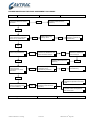
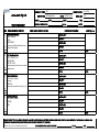
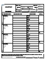
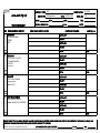
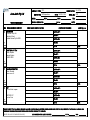
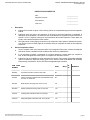
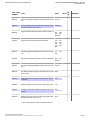
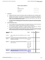
PERTH MAINTENANCE CONTROL OFFICE
WORK PACKAGE INSTRUCTIONS
AIRCRAFT TYPE: …CESSNA 208…… VH – OPH
DATE: …5-Nov-13…...
INSPECTION: … Interval Inspections … MC NUMBER: ……MC2013-1599….
ORGANISATION: …Aero Jacks Pty Ltd………..
No
1
2
3
Instruction
Transfer any open endorsements from current Maintenance Release to
Worksheets.
Complete the Inspections and events listed in Work Package – certify.
Complete the OSIP Inspections and events listed in Work Package.
Strike through items on Form 090 attached to Maintenance Release
Post immediately to:
NOTE - CHANGE OF ADDRESS
4
Mail ONLY:
Avtrac WA Pty Ltd
P.O.Box 568
Belmont WA 6984
Consigned Freight ONLY (No mail):
Avtrac WA Pty Ltd
Unit 2, 61 Belmont Avenue,
Belmont WA 6104
Paul Carey
Mobile: 0418 959 892
Avtrac WA Pty Ltd
Perth Maintenance Control Office
P.O.Box 568, Belmont WA 6984
Phone: (08) 9477 5205
Fax: (08) 9477 1170
Mobile: 0418 959 892
EXPIRED MAINTENANCE RELEASE ASSESSMENT PROCEDURE
VH-
Job No:
M/R No:
M/R Part 1:
Check issue details are correct in
top section.
MRO:
Notify issuing MRO and
Operator’s Chief Pilot of the
deficiency.
NO
YES
M/R Part 1:
Check “Maintenance Required”
section for any OPEN items.
YES
Check Part 2 for any
clearing action.
Notify issuing MRO and
Operator’s Chief Pilot of
the deficiency.
NO
NO
M/R Part 2:
Check for any OPEN items.
YES
Check Work Package to
determine of OPEN items have
been transferred through.
Notify issuing MRO and
Operator’s Chief Pilot of the
deficiency.
NO
M/R Part 2:
Check all cleared
endorsements for correct
certification.
Check current M/R and
determine if OPEN items
were transferred.
NO
NO
Check aircraft Log Books for a
certification for the
maintenance performed.
NO
NO
Notify the MRO or LAME
of the deficiency.
YES
Ensure current M/R totals (if
affected) are adjusted for the correct
totals.
M/R Part 3:
Check all progressive totals
are correct additions.
NO
Notify issuing MRO and
Operator’s Chief Pilot of the
deficiency.
Ensure Work Package TTIS and
Log Book entries are adjusted for
the correct totals.
Assessed by:
AVTRAC Maintenance Tracking
Date:
Form 038
Sig:
Initial Issue: 26th Aug 2011
Aero Jacks Pty Ltd
AIRCRAFT TYPE: 208
INSPECTION: M/R Inspections JOB No:
FORM 100 WORKSHEET
ITEM
1
Eng
WORK REQUIRED / DEFECT
REGISTRATION: VH - OPH
MC No MC2013-1599
VDO*:
JOB CO - ORDINATOR:
LDGS:
TTIS:
Lic No:
COMPLIANCE / RECTIFICATION
Maintenance Release
Action: Replace
CASA
S/N A082440
SERIAL No: 0157
DATE:
COMPONENT CHANGES
PART No OFF:
S/No OFF:
PART No ON:
Photocopy issued Maintenance Release and
include in Work Package.
S/No ON:
R/N No:
2
Eng
ELT Functional Test
IRN E-1 Action: Test
P/N 453-6603
S/N 197-11648
AME:
PART No OFF:
S/No OFF:
PART No ON:
Can be performed and certified by an Airframe
Category licence.
S/No ON:
R/N No:
3
Eng
Eng1
4
LAME Sig / Lic
Propeller Governor
IRN Action: Overhaul
3035926
12226116
AME:
PART No OFF:
S/No OFF:
PART No ON:
Cessna 208 Component Time Limits (2) (I) (2)
S/No ON:
R/N No:
Fuel Pump Vickers
IRN Action: Overhaul
3034792
0406
AME:
PART No OFF:
S/No OFF:
PART No ON:
S/No ON:
Eng
Eng1
R/N No:
AME:
I HEREBY CERTIFY THAT ALL WORK DETAILED HAS BEEN COMPLETED AND CERTIFIED FOR IN ACCORDANCE WITH THE REQUIREMENTS OF APPLICABLE MANUALS AND
SCHEDULES. THIS SIGNATURE CONSTITUTES A CERTIFICATION PURSUANT TO CAR 42ZE.
[* HEATER, APU, AIR CYCLE MACHINE VDO HOURS]
JOB CO-ORDINATOR: LAME SIGNATURE:
LIC No:
Date:
Aero Jacks Pty Ltd
AIRCRAFT TYPE: 208
INSPECTION: M/R Inspections JOB No:
FORM 100 WORKSHEET
ITEM
5
WORK REQUIRED / DEFECT
REGISTRATION: VH - OPH
VDO*:
JOB CO - ORDINATOR:
Fuel Control Unit
IRN Action: Overhaul
3244897-4
C65311
Lic No:
DATE:
COMPONENT CHANGES
LAME Sig / Lic
S/No OFF:
PART No ON:
S/No ON:
R/N No:
Oil to Fuel Heater
IRN Action: Overhaul
3032710
WA13250
AME:
PART No OFF:
S/No OFF:
PART No ON:
S/No ON:
R/N No:
Ignition Regulator
IRN Action: Overhaul
3035889
NN99317395
AME:
PART No OFF:
S/No OFF:
PART No ON:
S/No ON:
Eng
Eng1
8
TTIS:
PART No OFF:
Eng
Eng1
7
SERIAL No: 0157
LDGS:
COMPLIANCE / RECTIFICATION
Eng
Eng1
6
MC No MC2013-1599
R/N No:
Comp Bleed Valve
IRN Action: Overhaul
3049038-02
GA025
AME:
PART No OFF:
S/No OFF:
PART No ON:
S/No ON:
Eng
Eng1
R/N No:
AME:
I HEREBY CERTIFY THAT ALL WORK DETAILED HAS BEEN COMPLETED AND CERTIFIED FOR IN ACCORDANCE WITH THE REQUIREMENTS OF APPLICABLE MANUALS AND
SCHEDULES. THIS SIGNATURE CONSTITUTES A CERTIFICATION PURSUANT TO CAR 42ZE.
[* HEATER, APU, AIR CYCLE MACHINE VDO HOURS]
JOB CO-ORDINATOR: LAME SIGNATURE:
LIC No:
Date:
Aero Jacks Pty Ltd
AIRCRAFT TYPE: 208
INSPECTION: M/R Inspections JOB No:
FORM 100 WORKSHEET
ITEM
9
WORK REQUIRED / DEFECT
REGISTRATION: VH - OPH
VDO*:
JOB CO - ORDINATOR:
Flow Divider
IRN Action: Overhaul
3019906
20027
Eng
Eng1
11
TTIS:
Lic No:
DATE:
COMPONENT CHANGES
LAME Sig / Lic
PART No OFF:
S/No OFF:
PART No ON:
S/No ON:
R/N No:
Engine Insp
IRN B-3 Action: Carry Out
PT6 Health Check Run
P & W MM
AME:
PART No OFF:
S/No OFF:
PART No ON:
Use Form 009
S/No ON:
R/N No:
Engine Oil
IRN B-1 Action: Replace
AD/Eng/5 amd 8
Appendix A (7)
AME:
PART No OFF:
S/No OFF:
PART No ON:
S/No ON:
Eng
Eng1
12
SERIAL No: 0157
LDGS:
COMPLIANCE / RECTIFICATION
Eng
Eng1
10
MC No MC2013-1599
R/N No:
Power Recovery Wash
IRN B-4 Action: Carry Out
Catalina Airlines Pty Ltd C208 SOM
AME:
PART No OFF:
S/No OFF:
PART No ON:
S/No ON:
Eng
R/N No:
AME:
I HEREBY CERTIFY THAT ALL WORK DETAILED HAS BEEN COMPLETED AND CERTIFIED FOR IN ACCORDANCE WITH THE REQUIREMENTS OF APPLICABLE MANUALS AND
SCHEDULES. THIS SIGNATURE CONSTITUTES A CERTIFICATION PURSUANT TO CAR 42ZE.
[* HEATER, APU, AIR CYCLE MACHINE VDO HOURS]
JOB CO-ORDINATOR: LAME SIGNATURE:
LIC No:
Date:
Aero Jacks Pty Ltd
AIRCRAFT TYPE: 208
INSPECTION: M/R Inspections JOB No:
FORM 100 WORKSHEET
ITEM
13
WORK REQUIRED / DEFECT
REGISTRATION: VH - OPH
VDO*:
JOB CO - ORDINATOR:
Engine Chip Detector
IRN B-11 Action: Carry Out
AD/ENG/5 amd 8
Appendix A (6)
SERIAL No: 0157
LDGS:
TTIS:
Lic No:
COMPLIANCE / RECTIFICATION
DATE:
COMPONENT CHANGES
S/No OFF:
PART No ON:
S/No ON:
R/N No:
VFR/IFR Radio Periodic Inspection
Action: Inspect
Chapter 4
Catalina Airlines Pty Ltd SOM
AME:
PART No OFF:
S/No OFF:
PART No ON:
S/No ON:
Eng
R/N No:
15
1st Stage Compressor
IRN B-10 Action: Inspect
AD/Eng/5 amd 8
Appendix A (8)
AME:
PART No OFF:
S/No OFF:
PART No ON:
S/No ON:
Eng
Eng1
16
LAME Sig / Lic
PART No OFF:
Eng
Eng1
14
MC No MC2013-1599
R/N No:
Engine Oil Filter
IRN B-12 Action: Service
AD/Eng/5 amd 8
Appendix A (5)
AME:
PART No OFF:
S/No OFF:
PART No ON:
S/No ON:
Eng
Eng1
R/N No:
AME:
I HEREBY CERTIFY THAT ALL WORK DETAILED HAS BEEN COMPLETED AND CERTIFIED FOR IN ACCORDANCE WITH THE REQUIREMENTS OF APPLICABLE MANUALS AND
SCHEDULES. THIS SIGNATURE CONSTITUTES A CERTIFICATION PURSUANT TO CAR 42ZE.
[* HEATER, APU, AIR CYCLE MACHINE VDO HOURS]
JOB CO-ORDINATOR: LAME SIGNATURE:
LIC No:
Date:
Aero Jacks Pty Ltd
AIRCRAFT TYPE: 208
INSPECTION: M/R Inspections JOB No:
FORM 100 WORKSHEET
ITEM
17
WORK REQUIRED / DEFECT
REGISTRATION: VH - OPH
VDO*:
JOB CO - ORDINATOR:
Fuel Pump Outlet
Action: Replace
Filter P/N 3033355
Cessna MM
SERIAL No: 0157
LDGS:
TTIS:
Lic No:
COMPLIANCE / RECTIFICATION
DATE:
COMPONENT CHANGES
LAME Sig / Lic
PART No OFF:
S/No OFF:
PART No ON:
S/No ON:
Eng
Eng1
18
MC No MC2013-1599
R/N No:
Hand Held Cockpit Fwd
Action: Reweigh
Avtrac Form 010
AME:
PART No OFF:
S/No OFF:
PART No ON:
Eng
Use Form 010
S/No ON:
R/N No:
19
Eng
Life Jackets
Action: Inspect
Date inspection
Repetitive 100 Inspection
AME:
PART No OFF:
S/No OFF:
PART No ON:
Check for expire date on each jacket, packet is
sealed.
S/No ON:
R/N No:
20
Daily Inspection
Action: Inspect
Pilots Operating Handbook
Section 4
AME:
PART No OFF:
S/No OFF:
PART No ON:
S/No ON:
Eng
R/N No:
AME:
I HEREBY CERTIFY THAT ALL WORK DETAILED HAS BEEN COMPLETED AND CERTIFIED FOR IN ACCORDANCE WITH THE REQUIREMENTS OF APPLICABLE MANUALS AND
SCHEDULES. THIS SIGNATURE CONSTITUTES A CERTIFICATION PURSUANT TO CAR 42ZE.
[* HEATER, APU, AIR CYCLE MACHINE VDO HOURS]
JOB CO-ORDINATOR: LAME SIGNATURE:
LIC No:
Date:
Aero Jacks Pty Ltd
AIRCRAFT TYPE: 208
INSPECTION: M/R Inspections JOB No:
FORM 100 WORKSHEET
ITEM
21
WORK REQUIRED / DEFECT
REGISTRATION: VH - OPH
MC No MC2013-1599
VDO*:
JOB CO - ORDINATOR:
LDGS:
TTIS:
Lic No:
COMPLIANCE / RECTIFICATION
Engine
IRN B-2 Action: Inspect
Vibration Isolator Mounts
SERIAL No: 0157
DATE:
COMPONENT CHANGES
LAME Sig / Lic
PART No OFF:
S/No OFF:
PART No ON:
Eng
Eng1
22
Eng
Inspect for general condition, deterioation and
sagging.
S/No ON:
R/N No:
Aileron Trim
Action: Service
Actuator
P/N 2661615-1
AME:
PART No OFF:
S/No OFF:
PART No ON:
Disassemble, inspect and lubricate.
S/No ON:
R/N No:
23
Eng
100 Hour Inspection
A6 Action: Inspect
Float Inspection
Wipline 8000 SM
AME:
PART No OFF:
S/No OFF:
PART No ON:
Wipline Model 8000 Service Manual “Inspection
and Time Limits”
S/No ON:
R/N No:
24
Eng
200 Hour Inspection
A7 Action: Inspect
Float Inspection
Wipline 8000 SM
AME:
PART No OFF:
S/No OFF:
PART No ON:
Wipline Model 8000 Service Manual “Inspection
and Time Limits”
S/No ON:
R/N No:
AME:
I HEREBY CERTIFY THAT ALL WORK DETAILED HAS BEEN COMPLETED AND CERTIFIED FOR IN ACCORDANCE WITH THE REQUIREMENTS OF APPLICABLE MANUALS AND
SCHEDULES. THIS SIGNATURE CONSTITUTES A CERTIFICATION PURSUANT TO CAR 42ZE.
[* HEATER, APU, AIR CYCLE MACHINE VDO HOURS]
JOB CO-ORDINATOR: LAME SIGNATURE:
LIC No:
Date:
Aero Jacks Pty Ltd
AIRCRAFT TYPE: 208
INSPECTION: M/R Inspections JOB No:
FORM 100 WORKSHEET
ITEM
25
Eng
WORK REQUIRED / DEFECT
REGISTRATION: VH - OPH
MC No MC2013-1599
VDO*:
JOB CO - ORDINATOR:
LDGS:
TTIS:
Lic No:
COMPLIANCE / RECTIFICATION
25 Hour Inspection
A5 Action: Inspect
Float Inspection
Wipline 8000 SM
SERIAL No: 0157
DATE:
COMPONENT CHANGES
PART No OFF:
S/No OFF:
PART No ON:
Wipline Model 8000 Service Manual “Inspection
and Time Limits”
S/No ON:
R/N No:
26
Annual Inspection
5-15-OA Action: Inspect
Intervsl OA
Cessna CIP
AME:
PART No OFF:
S/No OFF:
PART No ON:
S/No ON:
Eng
R/N No:
27
Eng
Table 601
Action: Inspect
PART No OFF:
Pratt & Whitney PT6A-114A MM
PART No ON:
Photocopy issued Maintenance Release and
include in Work Package.
S/No ON:
AME:
S/No OFF:
R/N No:
28
LAME Sig / Lic
12 Month Inspection
5-15-01 Action: Inspect
Interval 1C Inspection
Cessna CIP
AME:
PART No OFF:
S/No OFF:
PART No ON:
S/No ON:
Eng
R/N No:
AME:
I HEREBY CERTIFY THAT ALL WORK DETAILED HAS BEEN COMPLETED AND CERTIFIED FOR IN ACCORDANCE WITH THE REQUIREMENTS OF APPLICABLE MANUALS AND
SCHEDULES. THIS SIGNATURE CONSTITUTES A CERTIFICATION PURSUANT TO CAR 42ZE.
[* HEATER, APU, AIR CYCLE MACHINE VDO HOURS]
JOB CO-ORDINATOR: LAME SIGNATURE:
LIC No:
Date:
Aero Jacks Pty Ltd
AIRCRAFT TYPE: 208
INSPECTION: M/R Inspections JOB No:
FORM 100 WORKSHEET
ITEM
29
WORK REQUIRED / DEFECT
REGISTRATION: VH - OPH
MC No MC2013-1599
VDO*:
JOB CO - ORDINATOR:
LDGS:
TTIS:
Lic No:
COMPLIANCE / RECTIFICATION
24 Month Inspection
5-15-02 Action: Inspect
Interval 2C Inspection
Cessna CIP
SERIAL No: 0157
DATE:
COMPONENT CHANGES
PART No OFF:
S/No OFF:
PART No ON:
S/No ON:
Eng
R/N No:
30
200hr - 12 month Inspection
5-15-06 Action: Inspect
Interval 200hrs/1C Inspection
Cessna CIP
AME:
PART No OFF:
S/No OFF:
PART No ON:
S/No ON:
Eng
R/N No:
31
800hr - 24 month Inspection
5-15-10 Action: Inspect
Interval 2A/2C Inspection
Cessna CIP
AME:
PART No OFF:
S/No OFF:
PART No ON:
S/No ON:
Eng
R/N No:
32
LAME Sig / Lic
1,600hr - 24 month Inspection
5-15-11 Action: Inspect
Interval 4A/2C Inspection
Cessna CIP
AME:
PART No OFF:
S/No OFF:
PART No ON:
S/No ON:
Eng
R/N No:
AME:
I HEREBY CERTIFY THAT ALL WORK DETAILED HAS BEEN COMPLETED AND CERTIFIED FOR IN ACCORDANCE WITH THE REQUIREMENTS OF APPLICABLE MANUALS AND
SCHEDULES. THIS SIGNATURE CONSTITUTES A CERTIFICATION PURSUANT TO CAR 42ZE.
[* HEATER, APU, AIR CYCLE MACHINE VDO HOURS]
JOB CO-ORDINATOR: LAME SIGNATURE:
LIC No:
Date:
Aero Jacks Pty Ltd
AIRCRAFT TYPE: 208
INSPECTION: M/R Inspections JOB No:
FORM 100 WORKSHEET
ITEM
33
WORK REQUIRED / DEFECT
REGISTRATION: VH - OPH
MC No MC2013-1599
VDO*:
JOB CO - ORDINATOR:
LDGS:
TTIS:
Lic No:
COMPLIANCE / RECTIFICATION
Main Battery
1.9 Action: Carry Out
Electrolyte Check
Catalina Airlines Pty Ltd SOM
SERIAL No: 0157
DATE:
COMPONENT CHANGES
PART No OFF:
S/No OFF:
PART No ON:
S/No ON:
Eng
R/N No:
34
Relief Valve Air Filter
Action: Replace
Vacuum System
C482001-0202
AME:
PART No OFF:
S/No OFF:
PART No ON:
S/No ON:
Eng
R/N No:
35
LAME Sig / Lic
Hand Held Cabin Fwd
Action: Reweigh
Avtrac Form 010
AME:
PART No OFF:
S/No OFF:
PART No ON:
S/No ON:
Eng
R/N No:
36
Eng
ELT
5-15-20 Action: Inspect
PART No OFF:
14CFR 91.207
PART No ON:
AME:
S/No OFF:
Functional Check
S/No ON:
R/N No:
AME:
I HEREBY CERTIFY THAT ALL WORK DETAILED HAS BEEN COMPLETED AND CERTIFIED FOR IN ACCORDANCE WITH THE REQUIREMENTS OF APPLICABLE MANUALS AND
SCHEDULES. THIS SIGNATURE CONSTITUTES A CERTIFICATION PURSUANT TO CAR 42ZE.
[* HEATER, APU, AIR CYCLE MACHINE VDO HOURS]
JOB CO-ORDINATOR: LAME SIGNATURE:
LIC No:
Date:
Print Date: Mon Nov 04 09:15:34 WST 2013
MODEL 208 MAINTENANCE MANUAL (Rev 26)
5-15-0A (Rev 26)
INSPECTION DOCUMENT 0A
1.
2.
Date:
_______________
Registration Number:
_______________
Serial Number:
_______________
Total Time:
_______________
Description
A.
Inspection Document 0A gives a list of item(s), which are completed during the Annual inspection
interval.
B.
Inspection items are given in the sequence of the zone in which the inspection is completed. A
description of the inspection, as well as the Item Code Number are supplied for cross-reference to
section 5-10-01. Frequently, tasks give more information about each inspection. These tasks are
found in the individual chapters of this manual.
C.
The right portion of each page gives space for the mechanic's and inspector's initials and remarks.
You can use copies of these pages as a checklist while you complete the tasks in this Inspection
Document.
General Inspection Criteria
A.
As you complete each of the inspection tasks in this Inspection Document, examine the adjacent
area while access is available to find conditions that need more maintenance.
B.
If it is necessary to replace a component or to make a change to a system while you complete a
task, do the task again before the system or component is returned to service.
C.
Inspection Kits are available for some Inspection Documents. They supply consumable materials
used to complete the inspection item(s) given for the interval. Refer to the Model 208 Illustrated
Parts Catalog, Introduction, Service Kit List to find applicable part numbers.
ITEM CODE
TASK
NUMBER
ZONE
A052001
Aircraft Records Check Task 5-20-01-280
A110001
Interior and Exterior Placard and Decal Detailed Inspec- ALL
tion Task 11-00-00-220
D121001
Brake System Servicing Task 12-10-01-610
121
D121003
Shimmy Damper Servicing Task 12-10-01-611
710
C122101
Landing Gear Lubrication Task 12-21-03-640
700
C122103
Hartzell Propeller Lubrication Task 12-21-04-640
110
© 2013 Cessna Aircraft Company
Retain printed data for historical reference only. For future maintenance, use only current data.
MECH
INSP
REMARKS
ALL
Page 1
Print Date: Mon Nov 04 09:15:34 WST 2013
ITEM CODE
TASK
NUMBER
MODEL 208 MAINTENANCE MANUAL (Rev 26)
5-15-0A (Rev 26)
ZONE
MECH
B212401
Avionics Cooling Fan Operational Check Task 21-24-00- 211 212
710
B221203
Garmin Autopilot (GFC 700) Slip Clutch Override Oper- 226 232
ational Check Task 22-12-00-710
B255201
Cargo Pod Drains Operational Check Task 25-52-00-710 901
902
903
904
905 906
C270001
Flight Controls Lubrication Task 27-00-00-640
215
226
374
525
625
216
373
503
603
B273101
Stall Warning System Operational Check Task 27-31-00- 211
710
503
212
C275001
Flap Tracks and Rollers Lubrication Task 27-50-00-640
A281001
Fuel Filler Assembly Detailed Inspection Task 28-10-01- 521 621
220
B284101
Fuel Reservoir Warning System Operational Check Task ENG
28-41-00-710
B313101
Flight Data Recorder System Functional Check Task 31- 312
31-00-720
B322001
Shimmy Damper Functional Check Task 32-20-02-720
A353001
Portable Oxygen Mask Detailed Inspection Task 35-30- 256
00-220
B761003
Emergency Power Lever Annunciator Light (EPL) Oper- AUX
ational Check Task 76-10-01-710
INSP
REMARKS
525
527
625 627
710
*** End of Inspection Document 0A Inspection Items ***
© 2013 Cessna Aircraft Company
Retain printed data for historical reference only. For future maintenance, use only current data.
Page 2
Print Date: Mon Nov 04 09:16:43 WST 2013
MODEL 208 MAINTENANCE MANUAL (Rev 26)
5-15-01 (Rev 25)
INSPECTION DOCUMENT 01
1.
2.
Date:
_______________
Registration Number:
_______________
Serial Number:
_______________
Total Time:
_______________
Description
A.
Inspection Document 01 gives a list of item(s), which are completed at every 12 calendar months.
B.
Inspection items are given in the sequence of the zone in which the inspection is completed. A
description of the inspection, as well as the Item Code Number are supplied for cross-reference to
section 5-10-01. Frequently, tasks give more information about each inspection. These tasks are
found in the individual chapters of this manual.
C.
The right portion of each page gives space for the mechanic's and inspector's initials and remarks.
You can use copies of these pages as a checklist while you complete the tasks in this Inspection
Document.
General Inspection Criteria
A.
As you complete each of the inspection tasks in this Inspection Document, examine the adjacent
area while access is available to find conditions that need more maintenance.
B.
If it is necessary to replace a component or to make a change to a system while you complete a
task, do the task again before the system or component is returned to service.
C.
Inspection Kits are available for some Inspection Documents. They supply consumable materials
used to complete the inspection item(s) given for the interval. Refer to the Model 208 Illustrated
Parts Catalog, Introduction, Service Kit List to find applicable part numbers.
ITEM CODE
TASK
NUMBER
ZONE
A251000
Smoke Goggle General Visual Inspection Task 25-10- 801 802
00-210
B262001
Portable Fire Extinguisher Functional Check (Weight 215
216
Check) Task 26-20-00-720
251 252
B272003
Rudder System Functional Check (Float Kit Installation) 211
212
Task 27-20-00-721
213
214
217
218
233
234
253
254
257
258
311
312
320 341
B301102
Inboard TKS Wing Panel Pressurization Functional 501, 601,
Check Task 30-11-00-721
AUX
© 2013 Cessna Aircraft Company
Retain printed data for historical reference only. For future maintenance, use only current data.
MECH
INSP
REMARKS
Page 1
Print Date: Mon Nov 04 09:16:43 WST 2013
ITEM CODE
TASK
NUMBER
MODEL 208 MAINTENANCE MANUAL (Rev 26)
5-15-01 (Rev 25)
ZONE
A321001
Main Landing Gear Detailed Inspection Task 32-10-00- 721 722
220
A324001
Brakes Detailed Inspection Task 32-40-00-220
A324005
Main Landing Gear Wheels and Tires Detailed Inspec- 721 722
tion Task 32-40-00-222
A324009
Nose Landing Gear Wheel and Tire Detailed Inspection 710
Task 32-40-00-224
B342101
Magnetic Compass Functional Check Task 34-21-00- ENG
720
B350101
Oxygen System Operational Check Task 35-01-00-710
A714101
Engine Wash Ring, Air Plenum, and Thermocouple (T1) 130
Detailed Inspection Task 71-41-00-220
MECH
INSP
REMARKS
721 722
231
232
251
252
255
256
311
312
801 802
*** End of Inspection Document 01 Inspection Items ***
© 2013 Cessna Aircraft Company
Retain printed data for historical reference only. For future maintenance, use only current data.
Page 2
Print Date: Wed Oct 23 13:08:20 WST 2013
MODEL 208 MAINTENANCE MANUAL (Rev 26)
5-15-02 (Rev 24)
INSPECTION DOCUMENT 02
1.
2.
Date:
_______________
Registration Number:
_______________
Serial Number:
_______________
Total Time:
_______________
Description
A.
Inspection Document 02 gives a list of item(s), which are completed at every 24 calendar months.
B.
Inspection items are given in the sequence of the zone in which the inspection is completed. A
description of the inspection, as well as the Item Code Number are supplied for cross-reference to
section 5-10-01. Frequently, tasks give more information about each inspection. These tasks are
found in the individual chapters of this manual.
C.
The right portion of each page gives space for the mechanic's and inspector's initials and remarks.
You can use copies of these pages as a checklist while you complete the tasks in this Inspection
Document.
General Inspection Criteria
A.
As you complete each of the inspection tasks in this Inspection Document, examine the adjacent
area while access is available to find conditions that need more maintenance.
B.
If it is necessary to replace a component or to make a change to a system while you complete a
task, do the task again before the system or component is returned to service.
C.
Inspection Kits are available for some Inspection Documents. They supply consumable materials
used to complete the inspection item(s) given for the interval. Refer to the Model 208 Illustrated
Parts Catalog, Introduction, Service Kit List to find applicable part numbers.
ITEM CODE
TASK
NUMBER
ZONE
B560001
Functional Check of the Windshield Task 56-00-01-720
A710001
Engine Compartment Zonal Inspection Task 71-00-01- 130
210
MECH
INSP
REMARKS
240
*** End of Inspection Document 02 Inspection Items ***
© 2013 Cessna Aircraft Company
Retain printed data for historical reference only. For future maintenance, use only current data.
Page 1
Print Date: Thu May 16 17:28:00 WST 2013
MODEL 208 MAINTENANCE MANUAL (Rev 26)
5-15-06 (Rev 26)
INSPECTION DOCUMENT 06
1.
2.
Date:
_______________
Registration Number:
_______________
Serial Number:
_______________
Total Time:
_______________
Description
A.
Inspection Document 06 gives a list of item(s), which are completed at every 200 Hours or 12
calendar months, whichever occurs first.
B.
Inspection items are given in the sequence of the zone in which the inspection is completed. A
description of the inspection, as well as the Item Code Number are supplied for cross-reference to
section 5-10-01. Frequently, tasks give more information about each inspection. These tasks are
found in the individual chapters of this manual.
C.
The right portion of each page gives space for the mechanic's and inspector's initials and remarks.
You can use copies of these pages as a checklist while you complete the tasks in this Inspection
Document.
General Inspection Criteria
A.
As you complete each of the inspection tasks in this Inspection Document, examine the adjacent
area while access is available to find conditions that need more maintenance.
B.
If it is necessary to replace a component or to make a change to a system while you complete a
task, do the task again before the system or component is returned to service.
C.
Inspection Kits are available for some Inspection Documents. They supply consumable materials
used to complete the inspection item(s) given for the interval. Refer to the Model 208 Illustrated
Parts Catalog, Introduction, Service Kit List to find applicable part numbers.
ITEM CODE
TASK
NUMBER
ZONE
MECH
B236001
Static Discharge System Functional Check Task 23-60- 343
00-720
376
671
B243401
Marathon Ni-Cad Battery Functional Check (Capacity 122
Check) Task 24-34-00-720
A255101
Cargo Nets Detailed Inspection Task 25-51-00-220
B281001
Fuel Vent Line Float Valve Operational Check Task 28- 575 675
10-03-710
© 2013 Cessna Aircraft Company
Retain printed data for historical reference only. For future maintenance, use only current data.
INSP
REMARKS
375
571
251
252
255
256
257 258
Page 1
Print Date: Thu May 16 17:28:00 WST 2013
ITEM CODE
TASK
NUMBER
MODEL 208 MAINTENANCE MANUAL (Rev 26)
5-15-06 (Rev 26)
ZONE
B301003
Bleed Air Pressure Regulator Functional Check (without 122 AUX
TKS and not incorporating CAB93-2) Task 30-10-00-720
B341101
Pitot Tube Heaters Operational Check Task 34-11-00- AUX
710
MECH
INSP
REMARKS
*** End of Inspection Document 06 Inspection Items ***
© 2013 Cessna Aircraft Company
Retain printed data for historical reference only. For future maintenance, use only current data.
Page 2
Print Date: Fri May 17 09:09:00 WST 2013
MODEL 208 MAINTENANCE MANUAL (Rev 26)
5-15-10 (Rev 26)
INSPECTION DOCUMENT 10
1.
2.
Date:
_______________
Registration Number:
_______________
Serial Number:
_______________
Total Time:
_______________
Description
A.
Inspection Document 10 gives a list of item(s), which are completed at every 800 Hours or 24
calendar months, whichever occurs first.
B.
Inspection items are given in the sequence of the zone in which the inspection is completed. A
description of the inspection, as well as the Item Code Number are supplied for cross-reference to
section 5-10-01. Frequently, tasks give more information about each inspection. These tasks are
found in the individual chapters of this manual.
C.
The right portion of each page gives space for the mechanic's and inspector's initials and remarks.
You can use copies of these pages as a checklist while you complete the tasks in this Inspection
Document.
General Inspection Criteria
A.
As you complete each of the inspection tasks in this Inspection Document, examine the adjacent
area while access is available to find conditions that need more maintenance.
B.
If it is necessary to replace a component or to make a change to a system while you complete a
task, do the task again before the system or component is returned to service.
C.
Inspection Kits are available for some Inspection Documents. They supply consumable materials
used to complete the inspection item(s) given for the interval. Refer to the Model 208 Illustrated
Parts Catalog, Introduction, Service Kit List to find applicable part numbers.
ITEM CODE
TASK
NUMBER
ZONE
C221201
Autopilot Servos Lubrication Task 22-12-00-640
A245001
Power Distribution Boxes Detailed Inspection Task 24- 121 122
50-00-220
A251001
Crew Seats Detailed Inspection Task 25-10-00-220
A251003
Passenger Seats Detailed Inspection Task 25-21-00-220 231 232
© 2013 Cessna Aircraft Company
Retain printed data for historical reference only. For future maintenance, use only current data.
MECH
INSP
REMARKS
226 232
231 232
Page 1
Print Date: Fri May 17 09:09:00 WST 2013
ITEM CODE
TASK
NUMBER
MODEL 208 MAINTENANCE MANUAL (Rev 26)
5-15-10 (Rev 26)
ZONE
B271001
Spoiler System Functional Check Task 27-10-00-720
C271003
Aileron Trim Tab Actuator (2660044-1) Lubrication Task 551
571
27-10-02-641
651 671
C273001
Elevator Trim Tab Actuator (2660017-1) Lubrication 371
372
Task 27-30-02-640
375 376
B284103
Fuel Quantity and Low Fuel Warning Systems Functional AUX
Check Task 28-41-00-720
B313103
Flight Data Recorder Underwater Locator Beacon Func- 312
tional Check Task 31-31-00-721
B324001
Brakes Operational Check Task 32-40-00-710
B332001
Passenger/Cargo Compartment Lighting Operational AUX
Check Task 33-20-00-710
A520001
Crew Doors Detailed Inspection Task 52-00-00-220
A520003
Passenger/Cargo Doors and Door Frames Detailed In- 255
256
spection Task 52-00-00-221
257
258
803 804
A781001
Primary and Secondary Exhaust Duct General Visual In- 130
spection Task 78-10-00-211
MECH
INSP
REMARKS
211
212
217
218
233
234
253
254
251
252
503
525
603 625
ENG
801 802
*** End of Inspection Document 10 Inspection Items ***
© 2013 Cessna Aircraft Company
Retain printed data for historical reference only. For future maintenance, use only current data.
Page 2
Print Date: Wed Oct 23 13:12:56 WST 2013
MODEL 208 MAINTENANCE MANUAL (Rev 26)
5-15-11 (Rev 24)
INSPECTION DOCUMENT 11
1.
2.
Date:
_______________
Registration Number:
_______________
Serial Number:
_______________
Total Time:
_______________
Description
A.
Inspection Document 11 gives a list of item(s), which are completed at every 1600 Hours or 24
calendar months, whichever occurs first.
B.
Inspection items are given in the sequence of the zone in which the inspection is completed. A
description of the inspection, as well as the Item Code Number are supplied for cross-reference to
section 5-10-01. Frequently, tasks give more information about each inspection. These tasks are
found in the individual chapters of this manual.
C.
The right portion of each page gives space for the mechanic's and inspector's initials and remarks.
You can use copies of these pages as a checklist while you complete the tasks in this Inspection
Document.
General Inspection Criteria
A.
As you complete each of the inspection tasks in this Inspection Document, examine the adjacent
area while access is available to find conditions that need more maintenance.
B.
If it is necessary to replace a component or to make a change to a system while you complete a
task, do the task again before the system or component is returned to service.
C.
Inspection Kits are available for some Inspection Documents. They supply consumable materials
used to complete the inspection item(s) given for the interval. Refer to the Model 208 Illustrated
Parts Catalog, Introduction, Service Kit List to find applicable part numbers.
ITEM CODE
TASK
NUMBER
ZONE
B271003
Aileron System Functional Check Task 27-10-00-721
B272001
Rudder System Functional Check (Standard Rudder In- 211
212
stallation) Task 27-20-00-720
213
214
217
218
233
234
253
254
257
258
311
312
320 341
© 2013 Cessna Aircraft Company
Retain printed data for historical reference only. For future maintenance, use only current data.
MECH
INSP
REMARKS
211
212
217
218
233
234
253
254
251
252
503
525
603 625
Page 1
Print Date: Wed Oct 23 13:12:56 WST 2013
ITEM CODE
TASK
NUMBER
MODEL 208 MAINTENANCE MANUAL (Rev 26)
5-15-11 (Rev 24)
ZONE
MECH
C272001
Rudder Bar Bearings and Rudder Pedals Lubrication 211
212
Task 27-20-00-640
213 214
B273001
Elevator System Functional Check Task 27-30-00-720
211
213
217
233
253
257
311
320
374
376
B275001
Flap System Functional Check Task 27-50-00-720
'251 252
511
611
525 625
INSP
REMARKS
212
214
218
234
254
258
312
373
375
*** End of Inspection Document 11 Inspection Items ***
© 2013 Cessna Aircraft Company
Retain printed data for historical reference only. For future maintenance, use only current data.
Page 2
PT6A-114A Maintenance Manual P/N3043512 Chapter 72-00-00 R29 Mar 08/2013
Table 601
PT6A-114A Table 601 Periodic Inspection Schedule
VH- ……….
Serial Number ……………….
Job Number ………………………..
TTIS ………………..
1
A
Date …………………
Job Co-ordinator ……………………………….
Landings …………………
ENGINE EXTERNALS
Tubing, Wiring,
(1) All accessible connections, clamps and
Control Linkages,
brackets for attachment.
Hose Assemblies
NOTE: Inspect accessible lockwire and safety
cable for security and installation.
(2) Wear, chafing, cracks and corrosion.
NOTE: Visually inspect insulated air tubes for
signs of swelling, cracking, bulging of rubber
sheath material. Refer to repair section and
SB1687. Replace as necessary.
(3) Fuel and oil lines for leaks.
(4) Depending on operating conditions and
environment, examine linkages at regular
intervals. Pay particular attention to rear linkage
cam box, fuel control unit arm, telescopic rod
and rod end fittings. Disconnect rod ends and
clean using solvent (PWC11-027) or (PWC11
031). Lubricate with light grease (PWC04-001)
after engine external wash.
Examine rod end for corrosion, roughness in
rotation, side play and radial play. After
lubrication reinstall rod ends and torque to
specified value (Ref 76-10-00). Check free
movement of linkage.
NOTE: With the exception of rod end fittings,
linkages generally will operate satisfactorily
without lubrication. While lubrication will be
effective in some instances, it must be realized
that grease and oil attracts dirt and foreign
matter. Depending on local conditions, operators
should take these facts into consideration before
deciding to lubricate components.
Cleanliness
(Ref. 72-20-00).
B
Air Inlet Screen
C
Gas Generator
Case
D
Fireseal Mount
Rings
E
Exhaust Duct
(1) Cracks and distortion
(Ref. 72-50-05, MAINTENANCE PRACTICES).
F
Propeller Shaft
Seal
Check for oil leaks
(Ref. 72-10-00)
External surfaces, and fireseal mount ring
brackets for cracks, distortion, and corrosion
(Ref. 72-30-04).
Cracks and attachment of brackets and seals.
(Ref. 72-30-01/-02)
Page 1
AME SIG
LAME SIG
PT6A-114A Maintenance Manual P/N3043512 Chapter 72-00-00 R29 Mar 08/2013
1
G
ENGINE EXTERNALS
Accessories
(1) Attachment and linkages, air, oil and fuel
lines (Ref. 73-10-07/-08).
NOTE: Visually inspect insulated air tubes for
signs of swelling, cracking, bulging of rubber
sheath material. Refer to repair section and
SB1687. Replace as necessary.
(2) Oil and fuel leaks as applicable.
(3) Starter Generator Gearshaft Splines for wear
2
A
B
ENGINE INTERNALS
Compressor
The CT disk and blade set must be sent for an
Turbine (CT) Disk
inspection per the overhaul manual instructions
Assembly
at the intervals that follow:
NOTE: 1 PT6A-114/114A: refer to SB1703.
Hot Section
(1) Examine with borescope (Ref. Para. 9).
3
A
SYSTEMS
Oil System
(1) Check oil level (Ref. SERVICING).
AME SIG
Table 601
LAME SIG
NOT APPLICABLE – OSIP
CARDS RAISED IN CONTROL
SYSTEM
AME SIG
LAME SIG
NOT APPLICABLE – OSIP
CARDS RAISED IN CONTROL
SYSTEM
AME SIG
LAME SIG
(2) Check condition and locking of oil filler cap
(Ref.72-60-00).
(3) Oil Filter Elements
Elements must be inspected and cleaned (Ref.
79-20-02). Light traces of sediment only may be
removed from the main filter screen. All other
contamination requires replacement of filter
element. Any foreign material found in main oil
filter or on chip detector, should be identified
before further inspection/operation (Ref. 79-2002, MAINTENANCE PRACTICES).
NOTE: 2 If carbon like deposits are found, drain
accessory gearbox oil into a clean container
and examine debris. Varnish flakes are non
metallic and are usually dark on one side and
shiny, similar to bronze, on the other side. They
are hard and will not form into paste when
rubbed between fingers (Ref. step (7).
Replace disposable filter elements PostSB1282).
Examine and clean permanentPre-SB1282) filter
elements at an overhaul facility. The filter may
be utilized for further 1500 hour periods,
maintaining the same inspection/cleaning
schedule.
(4) Check magnetic chip detector(s) for
continuity; open circuit must exist indicating no
contamination at pole tips. If continuity exists,
remove and inspect for contamination. Any
foreign material found on the chip detector or in
the main oil filter should be identified before
further inspection/operation (Ref. 79-20-02,
Inspection/Check).
Page 2
NOT APPLICABLE – OSIP
CARDS RAISED IN CONTROL
SYSTEM
PT6A-114A Maintenance Manual P/N3043512 Chapter 72-00-00 R29 Mar 08/2013
3
A
B
SYSTEMS (CONT)
Oil System (cont)
Fuel System
AME SIG
(5) Bridge chip detector(s) magnetic pins with
suitable jumper, and using a suitable ohmmeter,
check continuity between connector pins. If
continuity does not exist, replace chip detector.
Any foreign material found on chip detector or in
main oil filter should be identified before further
inspection/operation (Ref. 79-20-04,
MAINTENANCE PRACTICES).
(6) Check scavenge oil pump housing for leaks.
(7) Check the AGB internal scavenge oil pump
inlet screen (Ref. Chapter 72-60-00 CLEANING/
INSPECTION). Collect drained oil. Using a
mirror and a flashlight inspect the scavenge oil
pump inlet screen. Any foreign material found
blocking the screen or contained in the oil
should be identified before further operation
(Ref. Unscheduled Inspection).
(1) Check fuel for water contamination.
(2) Check fuel pump for installation and leaks
(Ref. 73-10-02).
NOTE: If airframe fuel boost pump fails or is
inadvertently left off for an accumulative time in
excess of 10 hours, the engine driven fuel pump
must be removed and replaced. The removed
pump should be sent to an approved overhaul
facility.
(3) Check inlet screen for foreign matter or
distortion, clean and reinstall, or install new
screen. (Ref. 73-10-02).
(4) Check outlet filter for foreign matter or
distortion
(Ref. 73-10-02). Install new filter as service
conditions dictate, not to exceed 600 hours and
when fuel system contamination is suspected.
(5) If Sundstrand fuel pump installed:
(a) Check fuel pump coupling in-situ for fretting
and corrosion (Ref. 73-10-02).
(b) Remove fuel pump and inspect the drive
coupling and cover accessory gearbox side for
signs of reddish-brown (iron oxide) stains. If
stains are observed, return the fuel pump to an
approved overhaul facility (Ref. 73-10-02).
(c) Remove fuel pump and inspect the drive
coupling and cover accessory gearbox side for
signs of reddish-brown (iron oxide) stains. If
stains are observed, return the fuel pump to an
approved overhaul facility (Ref. 73-10-02).
(6) Check drain valve for installation and leaks
(Ref. 73-10-06).
(7) Check FCU for installation, linkages and
pneumatic tubes (Ref. 73-20-00).
Page 3
Table 601
LAME SIG
NOT APPLICABLE – OSIP
CARDS RAISED IN CONTROL
SYSTEM
NOT APPLICABLE – NOT
OPERATING IN HIGH
RELATIVE
HUMIDITY/TROPICAL
ENVIRONMENT
NOT APPLICABLE – OSIP
CARDS RAISED IN CONTROL
SYSTEM
PT6A-114A Maintenance Manual P/N3043512 Chapter 72-00-00 R29 Mar 08/2013
3
B
SYSTEMS (CONT)
Fuel System (cont)
AME SIG
(8) For engines fitted with a manual override on
the fuel control, check FCU Manual Override
System for static operation (Ref. 71-00-00,
ADJUSTMENT/TEST).
(9) Check FCU for bearing wash-out, indicated
by blue dye (grease and fuel mixed) at FCU vent
(Ref. Fault Isolation - Operating Problems).
(10) (a) Remove FCU (Ref. 73-20-00) for drive
body inspection/driveshaft bearing replacement
in accordance with the component maintenance
manual (Ref. IPC P/N 3043514).
(10) (b) Remove FCU and send for overhaul.
Table 601
LAME SIG
NOT APPLICABLE – OSIP
CARDS RAISED IN CONTROL
SYSTEM
(11) Check starting flow control/flow divider for
installation and leaks (Ref. 73-10-04).
(12) Leak test and function test fuel manifold
adapter and nozzle assemblies (Ref. 73-10-05).
(13) Check oil-to-fuel heater installation (Ref.
73-10-01, MAINTENANCE PRACTICES).
C
Ignition System
NOT APPLICABLE – OSIP
CARDS RAISED IN CONTROL
SYSTEM
(1) Check ignition exciter/current regulator for
installation and condition (Ref. 74-10-00).
(2) Check ignition cables for chafing, wear and
installation (Ref. 74-20-00).
D
Pneumatic System
(3) Check spark igniter/glow plugs for
cleanliness and erosion. Check function (Ref.
74-20-00).
(1) Check P3 filter for installation
(Ref. 73-10-07).
(2) Inspect pneumatic tubes and lines for cracks
and damages especially at the end fittings and
joints.
(3) Clean or replace filter, dependent on
condition, service experience or environment
(Ref. 73-10-07).
NOTE: Visually inspect the P3 filter for
corrosion. If the filter shows presence of
corrosion, discard the filter and replace with a
new filter.
(4) Clean and inspect Post-SB1495 P3 filter
drain valve housing assembly (Ref. 73-10-07).
(5) Replace disposable filter based on condition,
service experience or environment.
(6) Clean or replace permanent filter based on
condition, service experience or environment.
Ship to an approved overhaul facility for
ultrasonic cleaning.
(7) Check the bleed valve (Ref. 75-30-00,
Inspection/Check)
END
Page 4
NOT APPLICABLE – OSIP
CARDS RAISED IN CONTROL
SYSTEM
WIPLINE MODEL 8000 SERVICE MANUAL
5.6 INSPECTION TIME LIMITS AND CHECKLIST
INSTRUCTIONS/PROCEEDURES
General
HOURLY LIMITS
General
Details
25
Wash aircraft and floats with fresh water
and inspect surfaces, hardware and strut
connections for corrosion.
If the airplane is exposed to salt- or
polluted water, the chances for
corrosion increase dramatically.
Daily basic cleaning is essential.
X
or
mor
eoft
en
50
Float Installation
Boarding steps: disassemble as needed
and grease the step slide tubes.
Disassemble and grease the flying wire
clevis bolts/pins.
Float
Interiors
Float structure (interior): pull up baggage
floors and inspect bulkheads.
Baggage compartment covers and seals inspect for condition, security, operation,
excessive wear and corrosion under
nutplates.
Pumper Tube Installation - inspect for
condition, security, routing of hoses.
Page 34 of 63
100 200 Annual Right Left
X
Check installed placards against the AFM
or POH, and installation drawings.
Hulls &
Struts
MECHANIC INSP.
X
Float exterior - inspect for damage,
wrinkled metal, corrosion, paint
loss, etc.
If the floats are installed, remove
the center section fairings for
access. Struts and attach fittings:
clean upper attach fittings and dog
bone saddle area. If off aircraft, regrease bolts and return.
Spreader Bars: inspect for loose
screws and cracks & seal between
fairing and side skin. Insp. fairings
for cracking and loose screws.
On the aircraft and floats: re-coat
exposed hardware with suitable
coating for corrosion protection.
Closely inspect for wrinkled metal &
cracked flanges; watch closely bulk
heads 9-21.
After hardware inspection, coat
with anti-corrosion grease to
protect.
X
X
X
X
X
X
X
X
X
X
X
X
X
1002554 • Rev H
X
WIPLINE MODEL 8000 SERVICE MANUAL
INSTRUCTIONS/PROCEEDURES
Water
Rudder
System
& Tail
Electrical
System
HOURLY LIMITS
General
Details
Water rudder boots - inspect for cuts,
tears, and condition
Water rudder blades and posts inspect for damage, security of
attachment, corrosion, paint,
rigging. Check post bolts and
bushings and lube with LPS 2.
Check top and bottom rollers for
rotation and lube with LPS 2 or
similar product.
Tension cables to
30 lbs. +/- 5
Water rudder steering and retract
systems - inspect the following: cables for
broken wire; fittings for cable slippage,
cracks and distortion; cable pulleys for
freedom of rotation and cable guard pins
for presence; rigging
On the aircraft: remove clean, inspect and
grease the aux. finlets on the horizontal
stabilizer.
Pump and indicator light wiring - inspect
for chafing, broken or loose terminals and
general condition.
Solenoids - inspect wiring, mounting and
general condition.
25
50
Nose gear box/block tracks
measured at slide route for wear,
.050 inches or less wear tolerance
Annual Right Left
X
X
X
X
Pump Motors - inspect wiring, mounting
and general condition.
Inspection and servicing nose gear
tracks:
100 200
X
Pressure Switches - inspect wiring,
mounting and general condition.
Landing
Gear
Systems
MECHANIC INSP.
Gold and white track and block
clean and use grease. Black track
and block – clean and dry or clean
and wipe with silicone spray.
Check side play – 3/32 to 1/16
inches max tolerance.
X
X
X
X
X
X
X
X
X
1002554 • Rev H
X
X
X
Page 35 of 63
WIPLINE MODEL 8000 SERVICE MANUAL
INSTRUCTIONS/PROCEEDURES
General
Details
Nose gear pivot blocks and forks - inspect
for condition, lubrication, corrosion, paint.
Nose & main wheel bearing - grease Zerks
Insp. Main gear slide tube, ram and locking
hooks for lubrication. Lube carriage zerk
liberally.
Hydraulic fluid level: Mil-H-5606
Grease with HCF p/n 605.
Spray locking hooks form the
top with LPS 2 to penetrate.
Wheels and tire - inspect for wear, pressure,
condition (45lbs +/_ 5lbs)
Brake assemblies - inspect for wear,
corrosion, leakage
Hydraulic fluid screen - clean and inspect.
NOTE: If floats sit for extended periods of
time (I.e. If removed during winter months),
screen should be cleaned before putting
floats back into service. Hydraulic fluid in
reservoir should be checked for moisture or
other contaminates and changed if
necessary.
Insp. FWD slide tube mounting bolt for
corrosion and wear when the gear are out.
Clean and lube the slide tube before
returning.
Main and Nose gear actuator, assemblies inspect for condition, lubrication, leakage,
corrosion, and cleanliness.
With gear out: Inspect FWD slide tube
mounting bolt for corrosion and wear. Clean
& grease FWD slide tube.
Nose gear springs - scotchply springs,
inspect for cracks, delamination and paint.
Main gear drag link garlock bushings inspect for condition, lubrication, and
corrosion.
Page 36 of 63
1002554 • Rev H
HOURLY LIMITS
25
50
MECHANIC INSP.
100 200 Annual Right Left
X
X
X
X
X
X
X
X
X
X
X
X
X
X
X
X
X
X
X
X
WIPLINE MODEL 8000 SERVICE MANUAL
INSTRUCTIONS/PROCEEDURES
HOURLY LIMITS
25
50
Clean the wheel wells to facilitate general
condition inspection.
Main gear oleos - inspect for evidence of
leakage, proper extension, check cylinder for
corrosion, pitting, cleanliness and security
Hydraulic lines and fittings - inspect for leaks,
condition and security.
MECHANIC INSP.
100 200 Annual
X
X
X
X
X
X
Hydraulic Manifolds (if equipped) - inspect for
condition, security, and leaks.
X
X
Brake system plumbing - inspect for leaks,
condition and security.
X
X
Main gear oleos – Check for static
compression, leaks and proper pressure. The
oleo should be fully serviced or replaced with
overhauled as required.
Perform retraction test:
Nose and main wheel bearings - disassemble
and inspect
Refer to section 5.2
If full servicing is required, use
5606 hydraulic fluid & Nitrogen
Refer to section 5.2
X
X
Inspect main gear up and down
lock hooks for proper
engagement.
X
X
Inspect nose gear trolley for
proper travel.
X
X
Inspect nose gear for excessive
play in the down position
X
X
Perform emergency gear
extension & retraction
X
X
Re-grease bearings with
recommended water resistant
grease
1002554 • Rev H
X
Right Left
X
Page 37 of 63
CATALINA AIRLINES PTY LTD
CESSNA 208
Aircraft
MAINTENANCE SYSTEM
IFR RADIO INSPECTION
VH-
Date
/
/
The radio systems & components detailed in this schedule shall be inspected or tested so as to ensure that
the system or component remains serviceable for the period between inspections subject to normal
operation, inservice maintenance and reporting. When carrying out an inspection, the Manufacturers
Maintenance Manual & Bulletins should be referred to for the complete inspection and test procedures.
------------------------------------------------------------------------------------------------
AME
LAME
(1) Accessible interwiring for security, damage and deterioration ;
microphones, headset cords for damage and deterioration;
accessible plugs and sockets for damage and security.
(2) Fuses for adequacy of spares. Check all active fuses for correct
type and rating.
(3) Wire aerials for fraying and deterioration ; fixed antennae for
damage and security ; associated fittings and supports for
security, deterioration and damage ; aerial insulators for freedom
from accumulated dirt and/or grease.
(4) Removable units for security in racks, isolators, mounting racks
and accessible bonding straps for damage, deterioration and security.
(5) Switches and controls for correct mechanical operation ; radio panel
lamps for serviceability, frequency charts, decals and controls for
legibility.
(6) Communication systems for correct performance .
(7) ADF system for accuracy and correct performance in all modes of
operation.
(8) VOR and ILS systems for correct operation using an approved
simulator.Test VOR on 0, 90, 180, 270 and one other widely separated
radial for system accuracy within the following limitations :Course Bar
Nav Indicator ...
tolerance ± 3 degrees
RMI’s..
tolerance ± 4 degrees
Course width ...
tolerance ± 8 to 12 degrees
Test LOC / GS function
On course ...
tolerance ± 0.5 dot
Up / left...
Down / right
tolerance ± 1 dot
tolerance ± 1 dots
A signature on this Document constitutes a certification pursuant to CAR 42ZE
Issue Date : 05 / 2013
CA / C208 / CIP / 013
1-RHEN Issue 07
Section 4 / Page 1 of 2
CATALINA AIRLINES PTY LTD
CESSNA 208
Aircraft
MAINTENANCE SYSTEM
IFR RADIO INSPECTION
VH-
Date
/
AME
(9)
Marker system for correct performance.
(10)
DME system for correct performance.
(11)
Weather radar system for correct performance.
(12)
Audio systems for correct operation.
(13)
ATC transponder for correct performance.
(14)
GPS system for correct operation.
(15)
T/CAS for correct operation.
(16)
Radio altimeter system for correct operation.
(17)
Inspect the Emergency Locator Transmitter Batteries for electrolyte
leakage and battery life.
/
LAME
POST INSPECTION CHECK
On completion of the inspection, check that no tooling, maintenance
equipment or rags have been left in the aircraft and all panels, access doors,
detachable fairings and fillets have been correctly secured.
**Equipment not fitted should be shown as N / F in LAME column. **
Refer Continued Airworthiness Requirements for all avionic equipment.
Note :- Correct performance or operation means meeting the system manufacturers
in service test specifications and tolerances in all functions.
A signature on this Document constitutes a certification pursuant to CAR 42ZE
Issue Date : 05 / 2013
CA / C208 / CIP / 013
1-RHEN Issue 07
Section 4 / Page 2 of 2
CATALINA AIRLINES PTY LTD
CESSNA 208
Aircraft
MAINTENANCE SYSTEM
VFR RADIO INSPECTION
VH-
Date
/
/
The radio systems & components detailed in this schedule shall be inspected or tested so as to ensure that the system or
component remains serviceable for the period between inspections subject to normal operation, inservice maintenance
and reporting.When carrying out an inspection, the Manufacturers Maintenance Manual & Bulletins should be referred
to for the complete inspection and test procedures.
----------------------------------------------------------------------------------------------- AME LAME
(1) Accessible interwiring for security, damage and deterioration ;
microphones, headset cords for damage and deterioration;
accessible plugs and sockets for damage and security.
(2) Fuses for adequacy of spares. Check all active fuses for correct
type and rating.
(3) Wire aerials for fraying and deterioration ; fixed antennae for
damage and security ; associated fittings and supports for
security, deterioration and damage ; aerial insulators for freedom
from accumulated dirt and/or grease.
(4) Removable units for security in racks, isolators, mounting racks
and accessible bonding straps for damage, deterioration and security.
(5) Switches and controls for correct mechanical operation ; radio panel
lamps for serviceability, frequency charts, decals and controls for
legibility.
(6) Communication / audio systems for correct performance .
(7) Inspect the Emergency Locator Transmitter Batteries for electrolyte
leakage and battery life.
Refer Continued Airworthiness Requirements for all avionic equipment
POST INSPECTION CHECK
On completion of the inspection, check that no tooling, maintenance
equipment or rags have been left in the aircraft and all panels, access doors,
detachable fairings and fillets have been correctly secured.
Radio inspection completed for VFR Operations ..
Signed ………………….. LAME No………….Date
/
/
Note :- Correct performance or operation means meeting the system manufacturers
in service test specifications and tolerances in all functions.
A signature on this Document constitutes a certification pursuant to CAR 42ZE
Issue Date : 05 / 2013
CA / C208 / CIP / 013
1-RHEN Issue 07
Section 5 / Page 1 of 1
CATALINA AIRLINES PTY LTD
CESSNA 208
Aircraft
MAINTENANCE SYSTEM
ADDITIONAL INSPECTION
VH-
Date
/
/
The inspections detailed in this schedule shall be inspected or tested so as to ensure that the system or component remains
serviceable for the period between inspections subject to normal operation, inservice maintenance and reporting. When
carrying out an inspection, the Manufacturers Maintenance Manual & Bulletins or releavant EO’s should be referred to for
the complete inspection and test procedures.
------------------------------------------------------------------------------------------------- AME LAME
Airframe Repairs
1.
Lower Fuselage Bulkhead Flange. EO 400-684
Inspect repaired area for security & corrosion
2.
Beam Truss repair. EO 400-447
Inspect repaired area for security & corrosion
3.
Vertical Fin Repair. EO 400-634
Inspect repaired area for security & corrosion
4.
Fuselage Bulkhead Repair. EO 400-662
Inspect repaired area for security & corrosion
5.
Beam Axle Repair. EO 400-620
Inspect repaired area for security & corrosion
POST INSPECTION CHECK
On completion of the inspection, check that no tooling, maintenance
equipment or rags have been left in the aircraft and all panels, access doors,
Notes .
Indicate results of inspection & any rectification necessary to maintain satisfactory condition.
…………………………………………………………………………………………………...
…………………………………………………………………………………………………...
……………………………………………………………………………………………………
…………………………………………………………………………………………………….
……………………………………………………………………………………………………
LAME Signature ………………………………. Date …………….
A signature on this document constitutes a certification pursuant to CAR 42ZE
Issue Date : 05 / 2013
CA / C208 / CIP / 013 1-RHEN Issue 07
Section 6 / Page 1 of 1
VHType:
J/N:
Extinguisher Pos:
P/N:
S/N:
Table 3.1 – Maintenance Schedule. Level 1, 2 and 3 Inspections for Vapourizing Liquid (Halon)
Extinguishers
No
1
2
Action Required.
Check that the extinguisher is conspicuous, readily accessible, and in
it’s assigned location, and the location sign is visible and correct.
Check that the anti-tamper device, where fitted, is intact.
3
Check that an appropriate support bracket is securely in place.
4
5
Check that the extinguisher is clean, that the instructions for operation
are clearly legible, and that the maintenance record tag (where
applicable) is attached.
Check that the extinguisher, including attachments, is not damaged.
6
Check that the exterior of the extinguisher is not pitted from corrosion.
7
Check that the discharge nozzle is the correct type.
8
Check that the discharge nozzle is not blocked or damaged, and the
hose is free from obstructions or cracking or other signs of damage or
deterioration, and is securely fitted.
Check that the extinguisher is fully charged eg by overall mass.
Record weight to two decimal places.
9
AME SIG
LAME SIG
____ . ____ ____ KG
10
11
12
Check that the pressure indicator mechanism, where fitted, is
registering within the operational range, and appears to be free and
operating correctly.
Where possible, without discharging any contents, check that the
actuating device is undamaged, free from corrosion, and moves freely.
Replace the extinguisher in the assigned location, and record
maintenance on maintenance tag (where applicable).
CASA CAO 103 Section 103.16 Issue 2 requirements
The following information at least, shall be clearly marked on each extinguisher (and able to be clearly read by
the pilot without removing the unit from it’s cradle):
No
1
2
3
4
Action Required.
Check the type of extinguisher is clearly marked; (write Halon in a
permanent marker, or affix a permanent tag)
Check that the termination date of current service life; (both the next 6
month inspection, and the 12 year inspection due dates – available
online) are clearly marked on the extinguisher, or tag.
Check the charged weight, or empty weight and weight charge is
clearly marked on the extinguisher, or tag.
Check the operating instructions and any special precautions for use
are clearly marked.
AME SIG
LAME SIG
Notes:
AVTRAC Maintenance Tracking
Form 010
Initial Issue: 25th May 2010
PT6 ENGINE GROUND RUN RECORD SHEET
Table 1
Rego:
Aircraft Type
And Model:
Type of check:
S/N:
Date:
Location:
OAT:
Field Baro:
Press Alt:
Table 2
Current Aircraft Status:
TTIS:
Cyc:
Ldgs:
Table 3
ENGINE POSITION
FF
ENGINE SERIAL NO
TARGET
OBSERVED
START ITT MAX LIMIT
START MAX ITT
PROP RPM (NP) (N2)
PROP RPM (NP) (N2)
TORQUE (TQ)
TORQUE (TQ)
ITT
ITT
FUEL FLOW (WF)
FUEL FLOW (WF)
GAS GEN (NG) (N1)
GAS GEN (NG) (N1)
OIL PRESSURE
OIL PRESSURE
Table 4
Remarks:
Table 5
LAME Signature:
AVTRAC Maintenance Tracking
Lic No:
Form 009
Date:
Initial Issue: 25th May 2010