1
User Manual
Version 4.6
Jungo Software Technologies
User Manual: Version 4.6
Jungo Software Technologies
Copyright © Jungo Ltd. 2007. All Rights Reserved. Jungo Confidential and Proprietary.
Product names mentioned in this document are trademarks of their respective manufacturers and are used here only for identification purposes.
Information in this document is subject to change without notice. The software described in this document is furnished under a license agreement.
The software may be used, copied or distributed only in accordance with that agreement. No part of this publication may be reproduced, stored in
a retrieval system, or transmitted in any form or any means, electronically or mechanically, including photocopying and recording for any purpose
without the written permission of Jungo Ltd.
This document is available for download at: http://www.jungo.com/openrg/manuals.html#4.6
Table of Contents
I. Getting Started ............................................................................................................................. 1
1. Introduction to OpenRG ........................................................................................................ 3
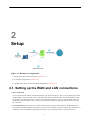
2. Setup ................................................................................................................................. 5
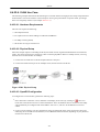
2.1. Setting up the WAN and LAN connections .................................................................... 5
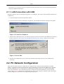
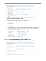
2.1.1. LAN Connection with USB .............................................................................. 6
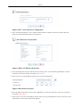
2.2. PC Network Configuration .......................................................................................... 6
II. Web-based Management ............................................................................................................... 9
3. Using the WBM ................................................................................................................. 14
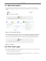
3.1. Web Interception ..................................................................................................... 15
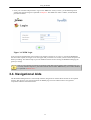
3.2. First Time Login ...................................................................................................... 15
3.3. Accessing the WBM ................................................................................................. 16
3.4. Navigational Aids .................................................................................................... 17
3.5. Managing Tables ..................................................................................................... 18
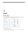
4. Home ............................................................................................................................... 20
4.1. Overview ................................................................................................................ 20
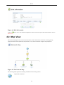
4.2. Map View .............................................................................................................. 22
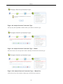
4.3. Installation Wizard ................................................................................................... 23
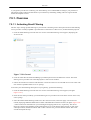
4.3.1. Step 1: Test Ethernet Link .............................................................................. 24
4.3.2. Step 2: Analyze Internet Connection Type .......................................................... 24
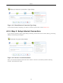
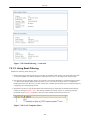
4.3.3. Step 3: Setup Internet Connection ..................................................................... 26
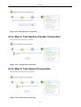
4.3.4. Step 4: Test Service Provider Connection ........................................................... 27
4.3.5. Step 5: Test Internet Connection ...................................................................... 27
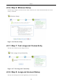
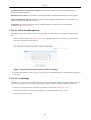
4.3.6. Step 6: Wireless Setup ................................................................................... 28
4.3.7. Step 7: Test Jungo.net Connectivity .................................................................. 28
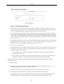
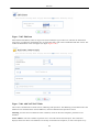
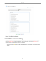
4.3.8. Step 8: Jungo.net Account Setup ...................................................................... 28
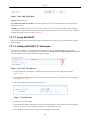
4.3.9. Step 9: Test Jungo.net Account ........................................................................ 32
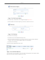
4.3.10. Step 10: Installation Completed ...................................................................... 32
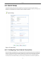
4.4. Quick Setup ............................................................................................................ 33
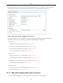
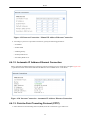
4.4.1. Configuring Your Internet Connection ............................................................... 33
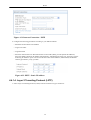
4.4.2. Wireless ....................................................................................................... 41
4.4.3. Jungo.net ...................................................................................................... 41
4.4.4. Quick Setup Completed .................................................................................. 42
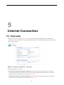
5. Internet Connection ............................................................................................................. 44
5.1. Overview ................................................................................................................ 44
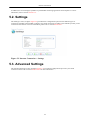
5.2. Settings .................................................................................................................. 45
5.3. Advanced Settings .................................................................................................... 45
5.4. Diagnostics ............................................................................................................. 46
6. Local Network ................................................................................................................... 48
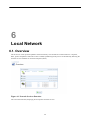
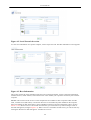
6.1. Overview ................................................................................................................ 48
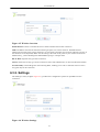
6.2. Device View ........................................................................................................... 50
6.3. Wireless ................................................................................................................. 50
6.3.1. Overview ..................................................................................................... 50
6.3.2. Settings ........................................................................................................ 51
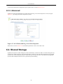
6.3.3. Advanced ..................................................................................................... 52
6.4. Shared Storage ........................................................................................................ 52
6.4.1. Partitioning ................................................................................................... 55
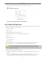
6.4.2. System Storage Area ...................................................................................... 62
6.4.3. RAID Management ........................................................................................ 63
6.5. Shared Printers ........................................................................................................ 68
6.5.1. Uploading Printer Drivers ............................................................................... 71
6.5.2. Printing with IPP ........................................................................................... 72
6.5.3. Printing with Samba ....................................................................................... 84
6.5.4. Printing with LPD ......................................................................................... 91
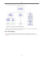
6.6. IP-PBX .................................................................................................................. 99
7. Services .......................................................................................................................... 101
7.1. Overview .............................................................................................................. 101
iv
User Manual
7.2. Jungo.net ..............................................................................................................
7.2.1. Creating a Jungo.net Account .........................................................................
7.2.2. Logging into Jungo.net .................................................................................
7.2.3. Using Jungo.net Services ...............................................................................
7.3. Firewall ................................................................................................................
7.3.1. Overview ....................................................................................................
7.3.2. Access Control ............................................................................................
7.3.3. Port Forwarding ...........................................................................................
7.3.4. DMZ Host ..................................................................................................
7.3.5. Port Triggering ............................................................................................
7.3.6. Website Restrictions .....................................................................................
7.3.7. Network Address Translation (NAT) ...............................................................
7.3.8. Connections ................................................................................................
7.3.9. Advanced Filtering .......................................................................................
7.3.10. Security Log ..............................................................................................
7.3.11. Applying Corporate-Grade Security ...............................................................
7.4. Quality of Service ..................................................................................................
7.4.1. Overview ....................................................................................................
7.4.2. Internet Connection Utilization .......................................................................
7.4.3. Traffic Priority ............................................................................................
7.4.4. Traffic Shaping ............................................................................................
7.4.5. Differentiated Services Code Point Settings ......................................................
7.4.6. 802.1p Settings ............................................................................................
7.4.7. Class Statistics ............................................................................................
7.4.8. Voice QoS Scenario .....................................................................................
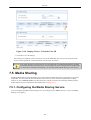
7.5. Media Sharing .......................................................................................................
7.5.1. Configuring the Media Sharing Service ............................................................
7.5.2. Accessing the Shared Media via LAN PC .........................................................
7.5.3. Accessing the Shared Media via UPnP Media Renderer .......................................
7.6. Voice Over IP .......................................................................................................
7.6.1. Physical Setup .............................................................................................
7.6.2. Line Settings ...............................................................................................
7.6.3. Speed Dial ..................................................................................................
7.6.4. Monitoring ..................................................................................................
7.6.5. Advanced ...................................................................................................
7.6.6. Telephone Operation ....................................................................................
7.6.7. Connecting OpenRG's VoIP to a World-Wide SIP Server ....................................
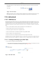
7.7. IP Private Branch Exchange .....................................................................................
7.7.1. Physical Setup .............................................................................................
7.7.2. Extensions ..................................................................................................
7.7.3. VoIP Accounts ............................................................................................
7.7.4. Auto Attendant ............................................................................................
7.7.5. Incoming Calls ............................................................................................
7.7.6. Outgoing Calls ............................................................................................
7.7.7. Music On-Hold ............................................................................................
7.7.8. Hunt Groups ...............................................................................................
7.7.9. Advanced ...................................................................................................
7.7.10. Using Your Home and Office PBX ...............................................................
7.8. Parental Control .....................................................................................................
7.8.1. Overview ....................................................................................................
7.8.2. Filtering Policy ............................................................................................
7.8.3. Advanced Options ........................................................................................
7.8.4. Statistics .....................................................................................................
7.9. Email Filtering .......................................................................................................
7.9.1. Overview ....................................................................................................
7.9.2. Advanced Options ........................................................................................
7.10. Virtual Private Network .........................................................................................
7.10.1. Internet Protocol Security ............................................................................
v
101
102
111
113
137
138
140
143
146
147
150
152
161
161
164
168
175
177
179
181
184
189
190
191
191
201
201
204
209
209
209
210
218
220
221
229
232
238
238
239
244
248
251
252
255
256
259
265
277
278
279
281
282
282
283
285
285
285
User Manual
7.10.2. Secure Socket Layer VPN ............................................................................
7.10.3. Point-to-Point Tunneling Protocol Server ........................................................
7.10.4. Layer 2 Tunneling Protocol Server ................................................................
7.11. Storage ...............................................................................................................
7.11.1. FTP Server ................................................................................................
7.11.2. File Server ................................................................................................
7.11.3. WINS Server .............................................................................................
7.11.4. Web Server ...............................................................................................
7.11.5. Mail Server ...............................................................................................
7.11.6. Backup and Restore ....................................................................................
7.12. Personal Domain Name (Dynamic DNS) ...................................................................
7.12.1. Opening a Dynamic DNS Account ................................................................
7.12.2. Using Dynamic DNS ..................................................................................
7.13. Advanced ............................................................................................................
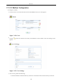
7.13.1. DNS Server ...............................................................................................
7.13.2. IP Address Distribution ...............................................................................
7.13.3. Bluetooth Settings ......................................................................................
7.13.4. RADIUS Server .........................................................................................
8. System ............................................................................................................................
8.1. Overview ..............................................................................................................
8.2. Settings ................................................................................................................
8.2.1. Overview ....................................................................................................
8.2.2. Date and Time ............................................................................................
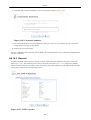
8.3. Users ....................................................................................................................
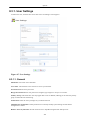
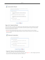
8.3.1. User Settings ...............................................................................................
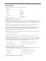
8.3.2. Group Settings ............................................................................................
8.4. Network Connections ..............................................................................................
8.4.1. The Connection Wizard ................................................................................
8.4.2. Network Types ............................................................................................
8.4.3. LAN Bridge ................................................................................................
8.4.4. LAN Ethernet ..............................................................................................
8.4.5. LAN USB ..................................................................................................
8.4.6. LAN Wireless .............................................................................................
8.4.7. WAN Ethernet ............................................................................................
8.4.8. Point-to-Point Protocol over Ethernet (PPPoE) ..................................................
8.4.9. Ethernet Connection .....................................................................................
8.4.10. Layer 2 Tunneling Protocol (L2TP) ...............................................................
8.4.11. Layer 2 Tunneling Protocol Server (L2TP Server) ............................................
8.4.12. Point-to-Point Tunneling Protocol (PPTP) .......................................................
8.4.13. Point-to-Point Tunneling Protocol Server (PPTP Server) ....................................
8.4.14. Internet Protocol Security (IPSec) ..................................................................
8.4.15. Internet Protocol Security Server (IPSec Server) ...............................................
8.4.16. Dynamic Host Configuration Protocol (DHCP) ................................................
8.4.17. Manual IP Address Configuration ..................................................................
8.4.18. Determine Protocol Type Automatically .........................................................
8.4.19. Point-to-Point Protocol over ATM (PPPoA) ....................................................
8.4.20. Ethernet over ATM (ETHoA) .......................................................................
8.4.21. Classical IP over ATM (CLIP) .....................................................................
8.4.22. WAN-LAN Bridge .....................................................................................
8.4.23. Virtual LAN Interface (VLAN) .....................................................................
8.4.24. Routed IP over ATM (IPoA) ........................................................................
8.4.25. Internet Protocol over Internet Protocol (IPIP) .................................................
8.4.26. General Routing Encapsulation (GRE) ...........................................................
8.5. Monitor ................................................................................................................
8.5.1. Network .....................................................................................................
8.5.2. CPU ..........................................................................................................
8.5.3. Log ...........................................................................................................
8.6. Routing ................................................................................................................
vi
322
338
340
342
342
345
360
362
364
369
371
371
371
373
373
374
379
379
396
396
396
396
399
402
403
404
405
407
418
419
427
429
431
461
467
474
475
484
487
495
498
500
501
502
504
505
512
516
521
532
540
544
548
552
552
552
553
554
User Manual
8.6.1. Overview ....................................................................................................
8.6.2. IPv6 ..........................................................................................................
8.6.3. BGP and OSPF ...........................................................................................
8.6.4. PPPoE Relay ...............................................................................................
8.7. Management ..........................................................................................................
8.7.1. Universal Plug and Play ................................................................................
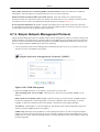
8.7.2. Simple Network Management Protocol ............................................................
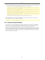
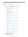
8.7.3. Remote Administration .................................................................................
8.7.4. Secure Shell ................................................................................................
8.8. Maintenance ..........................................................................................................
8.8.1. About OpenRG ............................................................................................
8.8.2. Configuration File ........................................................................................
8.8.3. Reboot .......................................................................................................
8.8.4. Restore Defaults ..........................................................................................
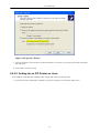
8.8.5. OpenRG Firmware Upgrade ...........................................................................
8.8.6. MAC Cloning .............................................................................................
8.8.7. Diagnostics .................................................................................................
8.9. Objects and Rules ..................................................................................................
8.9.1. Protocols ....................................................................................................
8.9.2. Network Objects ..........................................................................................
8.9.3. Scheduler Rules ...........................................................................................
8.9.4. Certificates .................................................................................................
9. Advanced ........................................................................................................................
III. Additional Features .................................................................................................................
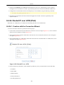
10. Zero Configuration Technology .........................................................................................
10.1. IP Auto-detection ..................................................................................................
10.2. Automatic Configuration for Non-Plug-and-Play Networks ...........................................
10.3. Network Map Builder ............................................................................................
11. Reducing Support Calls ....................................................................................................
11.1. Connection Problem Interception Page ......................................................................
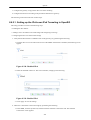
11.2. Forgotten Password for Wireless Network .................................................................
11.3. Configuration Backup ............................................................................................
11.4. Top Bandwidth Consumers .....................................................................................
IV. Appendix ...............................................................................................................................
12. List of Acronyms ............................................................................................................
13. Glossary ........................................................................................................................
14. Contact Jungo .................................................................................................................
vii
554
565
571
573
574
574
581
584
587
587
587
588
589
590
590
593
593
595
595
596
598
599
610
614
616
616
616
617
618
618
619
621
624
626
628
630
638
List of Figures
2.1. Hardware Configuration .............................................................................................................. 5
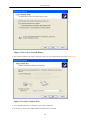
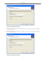
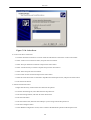
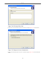
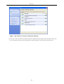
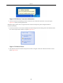
2.2. Found New Hardware ................................................................................................................ 6
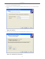
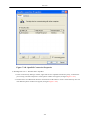
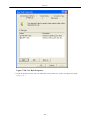
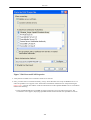
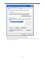
2.3. Insert Disk ............................................................................................................................... 6
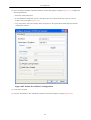
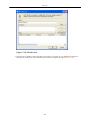
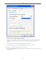
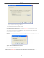
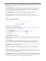
2.4. IP and DNS Configuration .......................................................................................................... 7
3.1. Web-based Management Home Page ........................................................................................... 14
3.2. Web Interception Message ......................................................................................................... 15
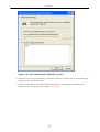
3.3. Attention ................................................................................................................................ 15
3.4. Welcome to OpenRG ............................................................................................................... 16
3.5. WBM First Time Login ............................................................................................................ 16
3.6. WBM Login ........................................................................................................................... 17
3.7. Navigation Components ............................................................................................................ 18
3.8. Constant Link Bar .................................................................................................................... 18
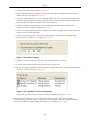
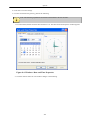
3.9. Typical Table Structure ............................................................................................................. 19
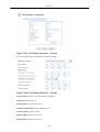
4.1. OpenRG Overview ................................................................................................................... 20
4.2. Internet Connection and Top Bandwidth Consumers ....................................................................... 21
4.3. Unformatted Storage Device Message .......................................................................................... 21
4.4. Disk Information ...................................................................................................................... 22
4.5. The Network Map .................................................................................................................... 22
4.6. Installation Wizard ................................................................................................................... 24
4.7. Test Ethernet Link ................................................................................................................... 24
4.8. Analyze Internet Connection Type .............................................................................................. 25
4.9. Analyze Internet Connection Type -- Failure ................................................................................. 25
4.10. Analyze Internet Connection Type -- Manual Set ......................................................................... 25
4.11. Manual Internet Connection Type Setup ..................................................................................... 26
4.12. Internet Account Information .................................................................................................... 26
4.13. Setup Internet Connection ........................................................................................................ 27
4.14. Test Internet Connection .......................................................................................................... 27
4.15. Test Internet Connection .......................................................................................................... 27
4.16. Wireless Setup ....................................................................................................................... 28
4.17. Test Jungo.net Connectivity ..................................................................................................... 28
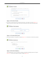
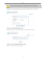
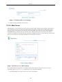
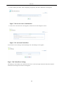
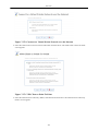
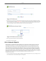
4.18. Jungo.net Account Setup ......................................................................................................... 29
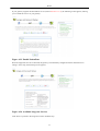
4.19. Jungo.net Account Setup -- Creating an Account .......................................................................... 29
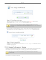
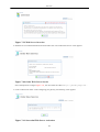
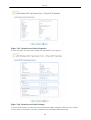
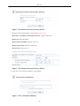
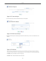
4.20. Configuring OpenRG with the Jungo.net Account ........................................................................ 30
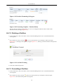
4.21. Successful Gateway Configuration ............................................................................................. 30
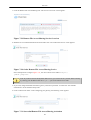
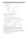
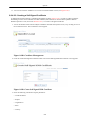
4.22. Detecting Jungo.net Services .................................................................................................... 30
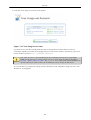
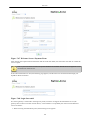
4.23. Enable NationZone ................................................................................................................. 31
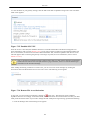
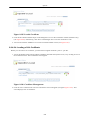
4.24. Available Jungo.net Services .................................................................................................... 31
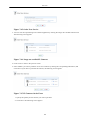
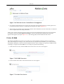
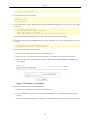
4.25. Test Jungo.net Account ........................................................................................................... 32
4.26. Installation Completed ............................................................................................................. 32
4.27. Quick Setup .......................................................................................................................... 33
4.28. Quick Setup - Multiple WAN Devices ....................................................................................... 34
4.29. Internet Connection - Manual IP Address Ethernet Connection ....................................................... 35
4.30. Internet Connection - Automatic IP Address Ethernet Connection .................................................... 35
4.31. Internet Connection - PPTP ...................................................................................................... 36
4.32. PPTP - Static IP Address ......................................................................................................... 36
4.33. Internet Connection - L2TP ...................................................................................................... 37
4.34. L2TP - Static IP Address ......................................................................................................... 37
4.35. Internet Connection - PPPoA .................................................................................................... 37
4.36. Manual PVC Scan Parameters .................................................................................................. 38
4.37. Internet Connection - Routed ETHoA ........................................................................................ 38
4.38. ETHoA - Static IP Address ...................................................................................................... 39
4.39. Internet Connection - Bridged ETHoA ....................................................................................... 39
4.40. Internet Connection - CLIP ...................................................................................................... 40
4.41. Internet Connection - PPPoE .................................................................................................... 40
4.42. Internet Connection - No Internet Connection .............................................................................. 41
4.43. Internet Connection - Wireless .................................................................................................. 41
viii
User Manual
4.44. Jungo.net ..............................................................................................................................
5.1. Internet Connection -- Overview .................................................................................................
5.2. Internet Connection -- Settings ...................................................................................................
5.3. Internet Connection -- Advanced Settings .....................................................................................
5.4. Internet Connection -- Diagnostics ..............................................................................................
5.5. Diagnostics Process ..................................................................................................................
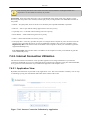
6.1. Network Services Detection .......................................................................................................
6.2. Local Network Overview ..........................................................................................................
6.3. Host Information ......................................................................................................................
6.4. Local Network Device View ......................................................................................................
6.5. Wireless Overview ...................................................................................................................
6.6. Wireless Settings .....................................................................................................................
6.7. LAN Wireless 802.11g Access Point Properties .............................................................................
6.8. Network Map ..........................................................................................................................
6.9. Disk Information ......................................................................................................................
6.10. NTFS Read-only Access ..........................................................................................................
6.11. Disk Management ..................................................................................................................
6.12. Manually Defined System Storage Area .....................................................................................
6.13. Disks ....................................................................................................................................
6.14. Partition Type ........................................................................................................................
6.15. Partition Size .........................................................................................................................
6.16. Partition Format .....................................................................................................................
6.17. Partition File System ...............................................................................................................
6.18. Partition Summary ..................................................................................................................
6.19. Partition Formatting in Progress ................................................................................................
6.20. Formatting Complete - Partition Ready ......................................................................................
6.21. Lost Data Warning .................................................................................................................
6.22. Partition Properties .................................................................................................................
6.23. Partition Format .....................................................................................................................
6.24. Lost Data Warning .................................................................................................................
6.25. Partition Formatting in Progress ................................................................................................
6.26. Formatting Complete - Partition Ready ......................................................................................
6.27. Partition Properties .................................................................................................................
6.28. Offline Partition Warning ........................................................................................................
6.29. Partition Checking in Progress ..................................................................................................
6.30. Checking Complete - Partition Ready ........................................................................................
6.31. Manually Defined System Storage Area .....................................................................................
6.32. System Storage Area Directories ...............................................................................................
6.33. RAID Properties ....................................................................................................................
6.34. Partition Format .....................................................................................................................
6.35. Partition File System ...............................................................................................................
6.36. Partition Summary ..................................................................................................................
6.37. RAID Devices .......................................................................................................................
6.38. RAID Properties ....................................................................................................................
6.39. Partition Properties .................................................................................................................
6.40. RAID Properties ....................................................................................................................
6.41. Printer on Network Map ..........................................................................................................
6.42. Printer Settings ......................................................................................................................
6.43. Print Server ...........................................................................................................................
6.44. OpenRG Shares .....................................................................................................................
6.45. Network Map ........................................................................................................................
6.46. Printer Settings ......................................................................................................................
6.47. Local or Network Printer .........................................................................................................
6.48. Specify a Printer ....................................................................................................................
6.49. Network Map ........................................................................................................................
6.50. Printer Settings ......................................................................................................................
6.51. Linux CUPS Management .......................................................................................................
6.52. Add Printer ...........................................................................................................................
ix
42
44
45
46
46
47
48
49
49
50
51
51
52
53
53
53
54
55
55
56
56
57
57
57
58
58
58
59
59
59
60
60
61
61
61
62
63
63
64
64
65
65
65
66
67
68
69
69
70
71
72
73
73
74
75
75
76
76
User Manual
6.53. Printer Name ......................................................................................................................... 77
6.54. Printing Protocol .................................................................................................................... 77
6.55. IPP URL ............................................................................................................................... 77
6.56. Network Map ........................................................................................................................ 78
6.57. Print & Fax ........................................................................................................................... 79
6.58. Printer Browser -- IP Printer .................................................................................................... 80
6.59. Print & Fax -- New IPP Printer ................................................................................................ 81
6.60. Print Queue Monitor ............................................................................................................... 81
6.61. Print Server ........................................................................................................................... 82
6.62. Users .................................................................................................................................... 82
6.63. User Settings ......................................................................................................................... 83
6.64. Printer Settings ...................................................................................................................... 83
6.65. Printer Access Control ............................................................................................................ 84
6.66. User Access Level .................................................................................................................. 84
6.67. Connect to Printer Warning ...................................................................................................... 85
6.68. Printer Queue ........................................................................................................................ 85
6.69. Network Map ........................................................................................................................ 86
6.70. Print & Fax ........................................................................................................................... 86
6.71. Printer Browser -- Default Browser ........................................................................................... 87
6.72. Printer Browser -- More Printers ............................................................................................... 87
6.73. Printer Browser -- Network Neighborhood .................................................................................. 88
6.74. Printer Browser -- Home ......................................................................................................... 88
6.75. Printer Browser -- OpenRG ...................................................................................................... 89
6.76. Printer Browser -- Printer Model ............................................................................................... 89
6.77. Print & Fax -- New Samba Printer ............................................................................................ 90
6.78. Local or Network Printer ......................................................................................................... 92
6.79. Select a Printer Port ................................................................................................................ 92
6.80. Add Port ............................................................................................................................... 93
6.81. Additional Port Information ..................................................................................................... 93
6.82. Printer Port Monitor Configuration ............................................................................................ 94
6.83. Add Printer Wizard ................................................................................................................ 95
6.84. Add Printer Wizard ................................................................................................................ 95
6.85. Network Map ........................................................................................................................ 96
6.86. Print & Fax ........................................................................................................................... 97
6.87. Printer Browser -- LPD Printer ................................................................................................. 98
6.88. Print & Fax -- New LPD Printer ............................................................................................... 99
6.89. PBX Main Screen ................................................................................................................. 100
7.1. Services Overview .................................................................................................................. 101
7.2. Jungo.net Account Setup ......................................................................................................... 102
7.3. Jungo.net Account Setup -- Creating an Account .......................................................................... 103
7.4. Configuring OpenRG with the Jungo.net Account ........................................................................ 103
7.5. Successful Gateway Configuration ............................................................................................. 104
7.6. Detecting Jungo.net Services .................................................................................................... 104
7.7. Enable NationZone ................................................................................................................. 105
7.8. Available Jungo.net Services .................................................................................................... 105
7.9. Jungo.net License Agreement ................................................................................................... 106
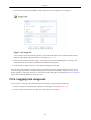
7.10. Registration Form ................................................................................................................. 106
7.11. Confirm Your Registration ..................................................................................................... 107
7.12. Detecting Supported Services .................................................................................................. 107
7.13. Supported Jungo.net Services .................................................................................................. 108
7.14. Welcome to Jungo.net ........................................................................................................... 108
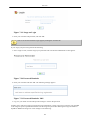
7.15. Registration Form ................................................................................................................. 109
7.16. Confirm Your Registration ..................................................................................................... 110
7.17. Registration Complete ........................................................................................................... 110
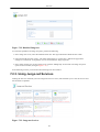
7.18. Jungo.net ............................................................................................................................. 111
7.19. Jungo.net Login .................................................................................................................... 112
7.20. Password Reminder ............................................................................................................... 112
7.21. Password Reminder Mail ....................................................................................................... 112
x
User Manual
7.22.
7.23.
7.24.
7.25.
7.26.
7.27.
7.28.
7.29.
7.30.
7.31.
7.32.
7.33.
7.34.
7.35.
7.36.
7.37.
7.38.
7.39.
7.40.
7.41.
7.42.
7.43.
7.44.
7.45.
7.46.
7.47.
7.48.
7.49.
7.50.
7.51.
7.52.
7.53.
7.54.
7.55.
7.56.
7.57.
7.58.
7.59.
7.60.
7.61.
7.62.
7.63.
7.64.
7.65.
7.66.
7.67.
7.68.
7.69.
7.70.
7.71.
7.72.
7.73.
7.74.
7.75.
7.76.
7.77.
7.78.
7.79.
Disabled Jungo.net ................................................................................................................
Jungo.net Services ................................................................................................................
Dynamic DNS Service Overview .............................................................................................
Order Dynamic DNS Service ..................................................................................................
Successful Dynamic DNS Activation .......................................................................................
Your Jungo.net Account ........................................................................................................
Active Dynamic DNS ............................................................................................................
Remote File Access/Sharing Service Overview ..........................................................................
Order Remote File Access/Sharing Service ................................................................................
Successful Remote File Access/Sharing Activation .....................................................................
Remote File Access Overview ................................................................................................
SSL-VPN Portal's Login Page .................................................................................................
My Network ........................................................................................................................
Enabled SSL-VPN ................................................................................................................
Remote File AccessInvitations ................................................................................................
Remote File Access Settings ...................................................................................................
Web Server's Disk Problem ....................................................................................................
Web Server Overview ...........................................................................................................
Order Web Server Service ......................................................................................................
Successful Web Server Activation ...........................................................................................
Your Jungo.net Account ........................................................................................................
Activated Web Server ...........................................................................................................
Service Overview .................................................................................................................
Order New Service ...............................................................................................................
Jungo.net-certified IP Cameras ................................................................................................
IP Cameras Order Form .........................................................................................................
IP Cameras Order Summary ...................................................................................................
IP Cameras Order Confirmation ..............................................................................................
Service Order Summary – Without Cameras ..............................................................................
Surveillance Order Confirmation .............................................................................................
Video Surveillance Overview ..................................................................................................
Surveilled Area ....................................................................................................................
Video Surveillance Settings ....................................................................................................
Rename Camera ...................................................................................................................
NationZone Overview ............................................................................................................
Order New Service ...............................................................................................................
Service Order Confirmation ....................................................................................................
Activated NationZone ............................................................................................................
NationZone Settings ..............................................................................................................
Your Jungo.net Account ........................................................................................................
Network Devices ..................................................................................................................
Virtual Access Point's Properties .............................................................................................
Virtual Access Point's Settings ................................................................................................
Login Page ..........................................................................................................................
Welcome Screen--Selecting AccessType ...................................................................................
Welcome Screen--Payment Form .............................................................................................
Login Successful ..................................................................................................................
Welcome Screen--NationZone is Unsupported ...........................................................................
IP-PBX Overview .................................................................................................................
Order New Service ...............................................................................................................
Select an Equipment Type ......................................................................................................
Order IP Phones ...................................................................................................................
IP PBX with IP Phones Order .................................................................................................
IP PBX with Softphones Order ...............................................................................................
Your Jungo.net Account ........................................................................................................
Activated Service Overview ...................................................................................................
IP-PBX Extensions ...............................................................................................................
VoIP Account from Jungo.net .................................................................................................
xi
113
113
114
115
115
116
116
117
117
117
118
118
118
119
119
120
120
121
121
121
122
123
123
124
124
124
125
125
125
125
126
126
126
127
127
127
128
128
128
129
129
130
130
131
131
132
132
133
133
133
134
134
134
135
135
135
135
136
User Manual
7.80. Edit VoIP Account ...............................................................................................................
7.81. VoIP Extensions ...................................................................................................................
7.82. OpenRG's Firewall in Action ..................................................................................................
7.83. General ...............................................................................................................................
7.84. Access Control .....................................................................................................................
7.85. Add Access Control Rule .......................................................................................................
7.86. Access Control Rule .............................................................................................................
7.87. Edit Access Control Rule .......................................................................................................
7.88. Port Forwarding ...................................................................................................................
7.89. Add Port Forwarding Rule .....................................................................................................
7.90. Specify Public IP Address ......................................................................................................
7.91. Forward to a Specific Port .....................................................................................................
7.92. Port Forwarding Rule ............................................................................................................
7.93. Edit Port Forwarding Rule .....................................................................................................
7.94. DMZ Host ...........................................................................................................................
7.95. Port Triggering .....................................................................................................................
7.96. Edit Port Triggering Rule .......................................................................................................
7.97. Edit Service Server Ports .......................................................................................................
7.98. Edit Service Server Ports .......................................................................................................
7.99. Edit Service Opened Ports ......................................................................................................
7.100. Edit Service Opened Ports ....................................................................................................
7.101. New Port Triggering Rule ....................................................................................................
7.102. Website Restrictions ............................................................................................................
7.103. Restricted Website ..............................................................................................................
7.104. Network Address Translation ................................................................................................
7.105. Edit Item ...........................................................................................................................
7.106. Add NAT/NAPT Rule .........................................................................................................
7.107. Add NAT Rule ...................................................................................................................
7.108. Add NAPT Rule .................................................................................................................
7.109. Add NAPT Rule .................................................................................................................
7.110. Edit Item ...........................................................................................................................
7.111. Edit Item ...........................................................................................................................
7.112. NAT IP Addresses ..............................................................................................................
7.113. Add NAT/NAPT Rule .........................................................................................................
7.114. Edit Network Object ............................................................................................................
7.115. Edit Item ...........................................................................................................................
7.116. NAT/NAPT Rule Sets .........................................................................................................
7.117. NAT/NAPT Rule Sets .........................................................................................................
7.118. Attention ...........................................................................................................................
7.119. NAT/NAPT Rule Sets .........................................................................................................
7.120. NAT/NAPT Rule Sets .........................................................................................................
7.121. Add NAPT Rule .................................................................................................................
7.122. NAT/NAPT Rule Sets .........................................................................................................
7.123. NAT/NAPT Rule Sets .........................................................................................................
7.124. Connection List ..................................................................................................................
7.125. Advanced Filtering ..............................................................................................................
7.126. Move Up and Move Down Action Icons .................................................................................
7.127. Add Advanced Filter ...........................................................................................................
7.128. Security Log ......................................................................................................................
7.129. Security Log Settings ...........................................................................................................
7.130. Enabling Secure Remote Administration .................................................................................
7.131. Apply Firewall Protection .....................................................................................................
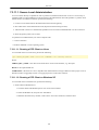
7.132. Installing the NULL Modem Driver .......................................................................................
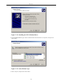
7.133. Select Modem Type ............................................................................................................
7.134. Select Ports ........................................................................................................................
7.135. Installing a Modem Driver ....................................................................................................
7.136. Select Modem Type ............................................................................................................
7.137. Select Ports ........................................................................................................................
xii
136
137
138
139
141
141
142
142
144
144
144
145
145
146
147
148
148
149
149
149
150
148
150
151
152
153
153
154
154
155
155
156
155
156
157
157
157
158
158
158
159
159
160
160
161
162
162
163
164
165
169
169
171
171
172
173
174
174
User Manual
7.138.
7.139.
7.140.
7.141.
7.142.
7.143.
7.144.
7.145.
7.146.
7.147.
7.148.
7.149.
7.150.
7.151.
7.152.
7.153.
7.154.
7.155.
7.156.
7.157.
7.158.
7.159.
7.160.
7.161.
7.162.
7.163.
7.164.
7.165.
7.166.
7.167.
7.168.
7.169.
7.170.
7.171.
7.172.
7.173.
7.174.
7.175.
7.176.
7.177.
7.178.
7.179.
7.180.
7.181.
7.182.
7.183.
7.184.
7.185.
7.186.
7.187.
7.188.
7.189.
7.190.
7.191.
7.192.
7.193.
7.194.
7.195.
End-to-end QoS Challenge Areas ...........................................................................................
OpenRG's QoS Architecture ..................................................................................................
General .............................................................................................................................
Internet Connection Utilization by Application .........................................................................
A Specific Application .........................................................................................................
Internet Connection Utilization by Computer ...........................................................................
A Specific Computer ...........................................................................................................
Traffic Priority ...................................................................................................................
Add Traffic Priority Rule .....................................................................................................
Set DSCP Rule ...................................................................................................................
Set Priority with Queueing ...................................................................................................
Move Up and Move Down Action Icons .................................................................................
Traffic Shaping ...................................................................................................................
Add Device Traffic Shaping .................................................................................................
Edit Device Traffic Shaping ..................................................................................................
TCP Serialization - Maximum Delay ......................................................................................
Add Shaping Class ..............................................................................................................
Edit Shaping Class ..............................................................................................................
Specify Maximum Bandwidth ...............................................................................................
Add Shaping Class ..............................................................................................................
Edit Policing Class ..............................................................................................................
Specify Maximum Bandwidth ...............................................................................................
DSCP--Traffic Priority Matching ...........................................................................................
Edit DSCP Settings .............................................................................................................
Traffic Queuing in 802.1p Settings .........................................................................................
Class Statistics ....................................................................................................................
Physical Setup ....................................................................................................................
Edit Service .......................................................................................................................
Edit Service Server Ports ......................................................................................................
Traffic Shaping ...................................................................................................................
Add Device Traffic Shaping .................................................................................................
Edit Device Traffic Shaping ..................................................................................................
Add Shaping Class ..............................................................................................................
Shaping Classes - Uncheck the Class ID .................................................................................
Edit Shaping Class ..............................................................................................................
Traffic Priority ...................................................................................................................
Add Traffic Priority Rule .....................................................................................................
Add Traffic Priority Rule--SIP Protocol ..................................................................................
Subclasses Section in Edit Shaping Class ................................................................................
Add Shaping Class ..............................................................................................................
Add Traffic Priority Rule--SIP Protocol ..................................................................................
FTP Process .......................................................................................................................
Traffic Shaping ...................................................................................................................
Shaping Classes - Check the Class ID ....................................................................................
Media Sharing ....................................................................................................................
Manual Folder Sharing Mode ................................................................................................
Folder Settings ...................................................................................................................
Manually Shared Partitions ...................................................................................................
Nero Home's Main Screen ....................................................................................................
MediaHome Network ...........................................................................................................
Jungo Media Server .............................................................................................................
Media Directories on a Partition ............................................................................................
Media Files in the Shared Directory .......................................................................................
Manually Shared Folders ......................................................................................................
Media Files in the Shared Directory .......................................................................................
Telephony Physical Setup .....................................................................................................
Line Settings ......................................................................................................................
General Line Parameters ......................................................................................................
xiii
176
177
178
179
180
180
181
182
183
184
184
184
185
186
186
187
187
187
188
188
189
189
190
190
191
191
192
193
192
193
194
194
195
195
196
196
197
197
198
198
199
200
200
201
202
203
203
204
205
205
206
207
207
208
209
210
210
211
User Manual
7.196. Line Parameters -- SIP Account .............................................................................................
7.197. SIP Proxy Parameters ..........................................................................................................
7.198. Line Parameters -- Outbound Proxy .......................................................................................
7.199. General Line Parameters ......................................................................................................
7.200. General Line Parameters ......................................................................................................
7.201. Line Parameters -- Services ..................................................................................................
7.202. Enable Call Forwarding Always ............................................................................................
7.203. Enable Call Forwarding on Busy ...........................................................................................
7.204. Enable Call Forwarding on No Answer ...................................................................................
7.205. Line Parameters -- SIP Account .............................................................................................
7.206. Line Parameters -- SIP Proxy ................................................................................................
7.207. Line Parameters -- Outbound Proxy .......................................................................................
7.208. Line Parameters -- Fax Transmission ......................................................................................
7.209. Line Parameters -- Numbering Plan ........................................................................................
7.210. Edit Prefix .........................................................................................................................
7.211. Line Parameters -- PSTN Failover .........................................................................................
7.212. Line Parameters -- Advanced SIP Settings ...............................................................................
7.213. Speed Dial .........................................................................................................................
7.214. Speed Dial - via Proxy .........................................................................................................
7.215. Speed Dial - Local Line .......................................................................................................
7.216. Speed Dial - Direct Call .......................................................................................................
7.217. Telephone Line Monitoring ...................................................................................................
7.218. Call Statistics .....................................................................................................................
7.219. Advanced – Signaling Protocol (RADVISION SIP Parameters) ...................................................
7.220. Advanced – Signaling Protocol (Asterisk SIP Parameters) ..........................................................
7.221. Advanced – Signaling Protocol (H.323 Parameters) ...................................................................
7.222. Advanced – Signaling Protocol (Asterisk H.323 Parameters) .......................................................
7.223. Advanced – Signaling Protocol (MGCP Parameters) ..................................................................
7.224. Advanced – Services ...........................................................................................................
7.225. Advanced – Real Time Protocol ............................................................................................
7.226. Advanced – Quality of Service ..............................................................................................
7.227. Advanced – Codecs .............................................................................................................
7.228. Advanced – Echo Cancellation ..............................................................................................
7.229. Advanced – Silence Suppression ............................................................................................
7.230. Advanced – Jitter Buffer ......................................................................................................
7.231. Advanced – FXS Ports .........................................................................................................
7.232. SIP Line Settings ................................................................................................................
7.233. SIP Proxy Parameters ..........................................................................................................
7.234. Outbound Proxy ..................................................................................................................
7.235. SIP Line Settings ................................................................................................................
7.236. SIP Proxy Parameters ..........................................................................................................
7.237. SIP Line Settings ................................................................................................................
7.238. SIP Proxy Parameters ..........................................................................................................
7.239. Outbound Proxy ..................................................................................................................
7.240. Line Parameters -- Advanced SIP Settings ...............................................................................
7.241. Telephony Physical Setup .....................................................................................................
7.242. PBX Main Screen ...............................................................................................................
7.243. Analog Extensions ..............................................................................................................
7.244. Edit Extension ....................................................................................................................
7.245. VoIP Extensions .................................................................................................................
7.246. Edit Extension -- SIP ...........................................................................................................
7.247. SIP Settings .......................................................................................................................
7.248. Edit Extension -- MGCP ......................................................................................................
7.249. VoIP Accounts Tab .............................................................................................................
7.250. Edit VoIP Account ..............................................................................................................
7.251. Limit Number of Simultaneous Calls ......................................................................................
7.252. SIP Account .......................................................................................................................
7.253. Line Parameters -- SIP Account .............................................................................................
xiv
211
211
212
212
213
213
213
213
214
214
214
215
215
216
217
217
218
218
219
219
220
221
221
222
223
223
224
225
225
225
226
226
227
227
228
229
233
233
234
235
235
236
237
237
238
239
239
239
240
240
241
242
242
244
245
245
246
246
User Manual
7.254.
7.255.
7.256.
7.257.
7.258.
7.259.
7.260.
7.261.
7.262.
7.263.
7.264.
7.265.
7.266.
7.267.
7.268.
7.269.
7.270.
7.271.
7.272.
7.273.
7.274.
7.275.
7.276.
7.277.
7.278.
7.279.
7.280.
7.281.
7.282.
7.283.
7.284.
7.285.
7.286.
7.287.
7.288.
7.289.
7.290.
7.291.
7.292.
7.293.
7.294.
7.295.
7.296.
7.297.
7.298.
7.299.
7.300.
7.301.
7.302.
7.303.
7.304.
7.305.
7.306.
7.307.
7.308.
7.309.
7.310.
7.311.
Line Parameters -- Outbound Proxy .......................................................................................
Line Parameters -- Advanced SIP Settings ...............................................................................
Edit VoIP Account ..............................................................................................................
Edit VoIP Account Group ....................................................................................................
Auto Attendant Tab .............................................................................................................
Edit Auto Attendant ............................................................................................................
Auto Attendant Greeting ......................................................................................................
Menu Options -- Transfer to Extension ...................................................................................
Menu Options -- Play Auto Attendant .....................................................................................
Incoming Calls Tab .............................................................................................................
Edit Incoming Call Handling .................................................................................................
Play Auto Attendant ............................................................................................................
Transfer to Extension ...........................................................................................................
Play Auto-Attendant If Busy or Unanswered ............................................................................
Outgoing Calls Tab .............................................................................................................
Edit Dial Plan Entry ............................................................................................................
Number of Digits to Remove ................................................................................................
Digits to Add .....................................................................................................................
Alternate Route 1 ................................................................................................................
Music On-Hold Tab ............................................................................................................
Browse For a Music File ......................................................................................................
Edit Auto Attendant ............................................................................................................
Edit Incoming Call Handling .................................................................................................
Hunt Groups Tab ................................................................................................................
Edit Hunt Group .................................................................................................................
Hunt Group Ring Mode .......................................................................................................
Extensions to Ring ..............................................................................................................
Ring Order .........................................................................................................................
Advanced -- Voice Mail .......................................................................................................
Advanced -- Call Park .........................................................................................................
Advanced -- SIP .................................................................................................................
Advanced -- MGCP .............................................................................................................
Advanced -- RTP ................................................................................................................
Advanced -- Quality of Service .............................................................................................
Advanced – Echo Cancellation ..............................................................................................
Advanced – Silence Suppression ............................................................................................
Advanced – Jitter Buffer ......................................................................................................
Advanced – FXS Ports .........................................................................................................
Advanced -- On Hook Caller ID Generation ............................................................................
Advanced -- Off Hook Caller ID Generation ............................................................................
Advanced -- Hook Flash ......................................................................................................
PBX Main Screen ...............................................................................................................
Edit Extension -- SIP ...........................................................................................................
VoIP Extensions .................................................................................................................
VoIP Accounts Tab .............................................................................................................
Edit VoIP Account ..............................................................................................................
Outbound Proxy ..................................................................................................................
VoIP Accounts ...................................................................................................................
Auto Attendant Tab .............................................................................................................
Edit Auto Attendant ............................................................................................................
Auto Attendant Greeting ......................................................................................................
Menu Options -- Play Auto Attendant .....................................................................................
Newly Created Auto Attendants .............................................................................................
Incoming Calls Tab .............................................................................................................
Edit Incoming Call Handling .................................................................................................
Edit Incoming Call Handling .................................................................................................
Incoming Call Handling .......................................................................................................
Outgoing Calls Tab .............................................................................................................
xv
246
247
248
248
249
249
250
250
250
251
251
252
252
252
253
253
254
254
255
255
256
256
256
257
257
257
258
258
259
259
260
261
261
261
262
262
263
264
264
265
265
266
266
267
268
269
270
270
270
271
271
272
272
273
273
274
274
275
User Manual
7.312.
7.313.
7.314.
7.315.
7.316.
7.317.
7.318.
7.319.
7.320.
7.321.
7.322.
7.323.
7.324.
7.325.
7.326.
7.327.
7.328.
7.329.
7.330.
7.331.
7.332.
7.333.
7.334.
7.335.
7.336.
7.337.
7.338.
7.339.
7.340.
7.341.
7.342.
7.343.
7.344.
7.345.
7.346.
7.347.
7.348.
7.349.
7.350.
7.351.
7.352.
7.353.
7.354.
7.355.
7.356.
7.357.
7.358.
7.359.
7.360.
7.361.
7.362.
7.363.
7.364.
7.365.
7.366.
7.367.
7.368.
7.369.
Edit Dial Plan Entry ............................................................................................................
Dial Pattern ........................................................................................................................
Number of Digits to Remove ................................................................................................
Digits to Add .....................................................................................................................
Dial Plan ...........................................................................................................................
General .............................................................................................................................
Filtering Policy ...................................................................................................................
Creating a Filtering Policy ....................................................................................................
LAN Computer Policy .........................................................................................................
Advanced Options ...............................................................................................................
Blocked Access ..................................................................................................................
Statistics ............................................................................................................................
General .............................................................................................................................
Email Filtering -- Activated ..................................................................................................
LAN Computer Inbox ..........................................................................................................
Advanced Options ...............................................................................................................
Internet Protocol Security (IPSec) ..........................................................................................
Internet Protocol Security (IPSec) Settings ...............................................................................
IPSec Log Settings ..............................................................................................................
VPN IPSec Properties -- General ...........................................................................................
VPN IPSec Properties -- Settings ...........................................................................................
VPN IPSec Properties -- Routing ...........................................................................................
VPN IPSec Properties -- IPSec ..............................................................................................
Automatic Key Exchange Settings .........................................................................................
Manual Key Definition ........................................................................................................
Network Connections ...........................................................................................................
Connection Wizard ..............................................................................................................
Connect to a Virtual Private Network over the Internet ..............................................................
VPN Client or Point-To-Point ...............................................................................................
Internet Protocol Security (IPSec) ..........................................................................................
Connection Summary ...........................................................................................................
New VPN IPSec Connection .................................................................................................
Local Security Settings ........................................................................................................
IP Security Policy Wizard ....................................................................................................
IP Security Policy Name ......................................................................................................
Requests for Secure Communication .......................................................................................
Completing the IP Security Policy Wizard ...............................................................................
OpenRG Connection Properties .............................................................................................
New Rule Properties ............................................................................................................
IP Filter List ......................................................................................................................
Filter Properties ..................................................................................................................
Filter Properties ..................................................................................................................
IP Filter List ......................................................................................................................
Filter Action ......................................................................................................................
Require Security Properties ...................................................................................................
Edit Authentication Method Properties ....................................................................................
Tunnel Setting ....................................................................................................................
IP Filter List ......................................................................................................................
Tunnel Setting ....................................................................................................................
OpenRG Connection Properties .............................................................................................
Local Security Settings ........................................................................................................
Configuration Diagram .........................................................................................................
Network Connections ...........................................................................................................
LAN Bridge Properties – General ..........................................................................................
LAN Bridge Properties – Settings ..........................................................................................
Network Connections ...........................................................................................................
WAN Ethernet Properties – General .......................................................................................
WAN Ethernet Properties – Settings .......................................................................................
xvi
275
275
276
276
276
278
279
280
281
281
282
282
283
284
284
285
286
287
288
289
289
290
290
292
294
294
295
295
296
296
297
297
298
298
299
299
300
301
302
303
304
305
306
306
307
308
309
309
310
310
311
311
311
312
312
313
313
314
User Manual
7.370.
7.371.
7.372.
7.373.
7.374.
7.375.
7.376.
7.377.
7.378.
7.379.
7.380.
7.381.
7.382.
7.383.
7.384.
7.385.
7.386.
7.387.
7.388.
7.389.
7.390.
7.391.
7.392.
7.393.
7.394.
7.395.
7.396.
7.397.
7.398.
7.399.
7.400.
7.401.
7.402.
7.403.
7.404.
7.405.
7.406.
7.407.
7.408.
7.409.
7.410.
7.411.
7.412.
7.413.
7.414.
7.415.
7.416.
7.417.
7.418.
7.419.
7.420.
7.421.
7.422.
7.423.
7.424.
7.425.
7.426.
7.427.
Network Connections ...........................................................................................................
Connection Wizard ..............................................................................................................
Connect to a Virtual Private Network over the Internet ..............................................................
VPN Client or Point-To-Point ...............................................................................................
Internet Protocol Security (IPSec) ..........................................................................................
Internet Protocol Security (IPSec) ..........................................................................................
Connection Summary ...........................................................................................................
VPN IPSec Properties – General ............................................................................................
Connected VPN IPSec Connection .........................................................................................
Load CA's Certificate ..........................................................................................................
Create X509 Request ...........................................................................................................
New X509 Request .............................................................................................................
Load OpenRG's Local Certificate ...........................................................................................
VPN IPSec Properties ..........................................................................................................
Connected VPN IPSec Connection .........................................................................................
SSL VPN ..........................................................................................................................
Enabled SSL VPN ..............................................................................................................
SSL VPN Portal .................................................................................................................
Remote Administration Ports .................................................................................................
Shortcut Wizard ..................................................................................................................
Choose Host from List .........................................................................................................
Select and Configure an Application .......................................................................................
Shortcut Summary ...............................................................................................................
Edit Shortcut ......................................................................................................................
User ..................................................................................................................................
Associated User ..................................................................................................................
Remote File Access Invitations Log .......................................................................................
Shortcuts ...........................................................................................................................
Save or Launch ..................................................................................................................
Launch ..............................................................................................................................
Web Based CIFS Parameters .................................................................................................
Shortcut to Application ........................................................................................................
Web-based CIFS Host .........................................................................................................
Web-based CIFS Share ........................................................................................................
Web-based CIFS Actions .....................................................................................................
CIFS Parameters .................................................................................................................
Remote Desktop Parameters ..................................................................................................
VNC Parameters .................................................................................................................
FTP Parameters ..................................................................................................................
Telnet Parameters ................................................................................................................
SSL VPN ..........................................................................................................................
Remote Administration Ports .................................................................................................
New User ..........................................................................................................................
New Shortcut .....................................................................................................................
Select and Configure an Application .......................................................................................
Telnet Parameters ................................................................................................................
Shortcut Summary ...............................................................................................................
Edit Shortcut ......................................................................................................................
User ..................................................................................................................................
Associated User ..................................................................................................................
New Telnet Shortcut ............................................................................................................
SSL VPN Portal .................................................................................................................
Telnet Session ....................................................................................................................
Point-to-Point Tunneling Protocol Server (PPTP Server) ............................................................
Advanced PPTP Server Parameters ........................................................................................
Layer 2 Tunneling Protocol Server (L2TP Server) .....................................................................
Advanced L2TP Server Parameters ........................................................................................
Users ................................................................................................................................
xvii
315
315
316
316
317
317
317
318
318
319
320
320
321
321
321
322
323
323
323
324
325
325
325
326
326
326
327
327
328
328
329
329
330
330
331
331
332
332
333
334
334
335
335
335
336
336
336
337
337
337
338
338
338
339
340
341
342
343
User Manual
7.428.
7.429.
7.430.
7.431.
7.432.
7.433.
7.434.
7.435.
7.436.
7.437.
7.438.
7.439.
7.440.
7.441.
7.442.
7.443.
7.444.
7.445.
7.446.
7.447.
7.448.
7.449.
7.450.
7.451.
7.452.
7.453.
7.454.
7.455.
7.456.
7.457.
7.458.
7.459.
7.460.
7.461.
7.462.
7.463.
7.464.
7.465.
7.466.
7.467.
7.468.
7.469.
7.470.
7.471.
7.472.
7.473.
7.474.
7.475.
7.476.
7.477.
7.478.
7.479.
7.480.
7.481.
7.482.
7.483.
7.484.
7.485.
User Settings ......................................................................................................................
Enabled FTP Server ............................................................................................................
Anonymous Access .............................................................................................................
File Server .........................................................................................................................
Disabled Automatic Partition Sharing .....................................................................................
File Server Share Settings .....................................................................................................
File Server Share ................................................................................................................
File Share Actions ...............................................................................................................
Upload a File to the Share ....................................................................................................
Create a New Directory .......................................................................................................
File Share Content ..............................................................................................................
Remote File Access Invitations ..............................................................................................
Users ................................................................................................................................
User Settings ......................................................................................................................
File Server Share Settings .....................................................................................................
User Access Settings ...........................................................................................................
File Server Shares Section ....................................................................................................
Login Dialog ......................................................................................................................
File Share ..........................................................................................................................
File Server Share ................................................................................................................
Invitation Form ...................................................................................................................
Invitation Status ..................................................................................................................
File Server Shares ...............................................................................................................
Invitation Message ..............................................................................................................
Shortcut to Share ................................................................................................................
Remote File Server Share .....................................................................................................
File Properties ....................................................................................................................
Select Users or Groups ........................................................................................................
Users or Groups List ...........................................................................................................
Connect to Server ...............................................................................................................
Connect to Server ...............................................................................................................
Connect to Server ...............................................................................................................
WINS Server ......................................................................................................................
WINS Server ......................................................................................................................
Web Server ........................................................................................................................
Data Location Field .............................................................................................................
User Private Web Page ........................................................................................................
Virtual Host .......................................................................................................................
Virtual Host Aliases ............................................................................................................
New Virtual Host ................................................................................................................
Mail Server ........................................................................................................................
Enabled Mail Server ............................................................................................................
Users ................................................................................................................................
User Settings ......................................................................................................................
Mail Box Aliases ................................................................................................................
Mailing Lists ......................................................................................................................
Mailing Lists ......................................................................................................................
New Mailing List ................................................................................................................
Backup and Restore .............................................................................................................
Edit Backup .......................................................................................................................
Edit Restore .......................................................................................................................
Dynamic DNS ....................................................................................................................
Dynamic DNS ....................................................................................................................
SSL Mode .........................................................................................................................
DNS Table .........................................................................................................................
Add or Edit a DNS Entry .....................................................................................................
IP Address Distribution ........................................................................................................
DHCP Settings for LAN Bridge ............................................................................................
xviii
343
344
345
345
346
347
347
348
348
348
348
349
349
350
350
351
351
352
352
353
354
354
355
355
355
356
357
358
359
360
360
360
361
361
362
363
363
364
364
363
365
365
366
366
367
368
368
367
369
370
371
371
372
373
373
374
375
375
User Manual
7.486. DHCP Settings for LAN Bridge ............................................................................................
7.487. DHCP Relay Server Address .................................................................................................
7.488. Configure WAN Ethernet -- Routing ......................................................................................
7.489. DHCP Connections .............................................................................................................
7.490. DHCP Connection Settings ...................................................................................................
7.491. DHCP Connections .............................................................................................................
7.492. Bluetooth Settings ...............................................................................................................
7.493. RADIUS Server Scenario .....................................................................................................
7.494. RADIUS Server ..................................................................................................................
7.495. Add RADIUS Client ...........................................................................................................
7.496. Newly Added Client ............................................................................................................
7.497. EAP-TLS Authentication ......................................................................................................
7.498. LAN Wireless Settings .........................................................................................................
7.499. Wireless Network Connection Window ...................................................................................
7.500. Wireless Network Connection Properties Window .....................................................................
7.501. Connection Properties Window ..............................................................................................
7.502. Negotiation with the EAP PEAP MSCHAP v2 Algorithm ..........................................................
7.503. Connection Properties Window -- EAP PEAP Algorithm ............................................................
7.504. Protected EAP Properties .....................................................................................................
7.505. Certificates .........................................................................................................................
7.506. Cerificate ...........................................................................................................................
7.507. Certificate Import Wizard .....................................................................................................
7.508. EAP MSCHAPv2 Properties .................................................................................................
7.509. Wireless Network Connection Message ...................................................................................
7.510. Enter Credentials ................................................................................................................
7.511. Negotiation with the EAP TLS Algorithm ...............................................................................
7.512. Connection Properties Window -- EAP TLS Algorithm ..............................................................
7.513. Smart Card or other Certificate Properties ...............................................................................
7.514. Certificate Import Wizard .....................................................................................................
7.515. CA's .................................................................................................................................
7.516. Load CA's Certificate ..........................................................................................................
8.1. System Monitoring Overview ...................................................................................................
8.2. System Settings ......................................................................................................................
8.3. Date and Time Settings ...........................................................................................................
8.4. Windows--Date and Time Properties ..........................................................................................
8.5. Windows--Internet Time Screen ................................................................................................
8.6. Users ....................................................................................................................................
8.7. User Settings .........................................................................................................................
8.8. Group Settings .......................................................................................................................
8.9. Network Connections - Basic ...................................................................................................
8.10. Network Connections - Advanced ............................................................................................
8.11. Connection Wizard ...............................................................................................................
8.12. Internet Connection Wizard Screen ..........................................................................................
8.13. Internet Connection Wizard Tree .............................................................................................
8.14. VPN Wizard Screen ..............................................................................................................
8.15. VPN Wizard Tree .................................................................................................................
8.16. Advanced Connection Wizard Screen .......................................................................................
8.17. Advanced Connection Wizard Tree ..........................................................................................
8.18. DSL Connection Wizard ........................................................................................................
8.19. Internet DSL Connection Wizard Screen ...................................................................................
8.20. Internet DSL Connection Wizard Tree ......................................................................................
8.21. VPN Wizard Screen ..............................................................................................................
8.22. VPN Wizard Tree .................................................................................................................
8.23. Advanced DSL Connection Wizard Screen ................................................................................
8.24. Advanced DSL Connection Wizard Tree ...................................................................................
8.25. Bridge Options .....................................................................................................................
8.26. Network Bridging -- Configure Existing Bridge .........................................................................
8.27. Network Bridging -- Add a New Bridge ...................................................................................
xix
376
377
377
378
378
378
379
380
380
381
381
382
383
384
385
386
387
387
388
389
389
390
390
391
391
392
392
393
394
395
395
396
397
400
401
402
402
403
405
405
406
408
408
409
409
410
411
412
413
414
415
415
416
417
418
419
420
420
User Manual
8.28. Connection Summary - Configure Existing Bridge ......................................................................
8.29. LAN Bridge Properties ..........................................................................................................
8.30. General ...............................................................................................................................
8.31. Internet Protocol -- No IP Address ...........................................................................................
8.32. Internet Protocol Settings -- Automatic IP .................................................................................
8.33. Internet Protocol -- Static IP ...................................................................................................
8.34. DNS Server -- Automatic IP ...................................................................................................
8.35. DNS Server -- Static IP .........................................................................................................
8.36. IP Address Distribution -- DHCP Server ...................................................................................
8.37. IP Address Distribution - DHCP Relay .....................................................................................
8.38. DHCP Relay Server Address ..................................................................................................
8.39. IP Address Distribution - Disable DHCP ..................................................................................
8.40. Advanced Routing Properties ..................................................................................................
8.41. LAN Bridge Settings .............................................................................................................
8.42. IPv6 Settings .......................................................................................................................
8.43. Internet Connection Firewall ...................................................................................................
8.44. Additional IP Addresses .........................................................................................................
8.45. LAN Ethernet Properties ........................................................................................................
8.46. General ...............................................................................................................................
8.47. Internet Connection Firewall ...................................................................................................
8.48. Internet Connection Fastpath ...................................................................................................
8.49. Additional IP Addresses .........................................................................................................
8.50. LAN USB Properties .............................................................................................................
8.51. General ...............................................................................................................................
8.52. Internet Connection Firewall ...................................................................................................
8.53. Additional IP Addresses .........................................................................................................
8.54. OpenRG for Wireless Gateways Authentication and Encryption Components ...................................
8.55. LAN Wireless 802.11g Access Point Properties -- Disabled ..........................................................
8.56. Wireless Access Point ...........................................................................................................
8.57. Network Connections ............................................................................................................
8.58. Available Wireless Connections ..............................................................................................
8.59. Connected Wireless Network ..................................................................................................
8.60. Wireless Connection Information .............................................................................................
8.61. Web Authentication ..............................................................................................................
8.62. Web Authentication ..............................................................................................................
8.63. Wireless Login .....................................................................................................................
8.64. Forgotten Password for Wireless Network .................................................................................
8.65. Jungo.net Login ....................................................................................................................
8.66. Wireless LAN User ...............................................................................................................
8.67. New User Created ................................................................................................................
8.68. Enter a New User Name and Password Using a Wired Connection .................................................
8.69. Reset Factory Settings ...........................................................................................................
8.70. Contact the Support Center .....................................................................................................
8.71. LAN Wireless 802.11g Access Point Properties -- Enabled ...........................................................
8.72. WPA Wireless Security Parameters ..........................................................................................
8.73. Browser Reload Warning .......................................................................................................
8.74. Network Connections ............................................................................................................
8.75. Available Wireless Connections ..............................................................................................
8.76. Wireless Network Connection Login ........................................................................................
8.77. Connected Wireless Network ..................................................................................................
8.78. Wireless Connection Information .............................................................................................
8.79. Related Tasks ......................................................................................................................
8.80. Wireless Network Connection Properties ...................................................................................
8.81. Connection Properties Configuration ........................................................................................
8.82. LAN Wireless 802.11g Access Point Properties -- Enabled ...........................................................
8.83. General ...............................................................................................................................
8.84. Wireless Access Point ...........................................................................................................
8.85. MAC Filtering Settings ..........................................................................................................
xx
421
421
422
422
423
423
423
423
424
424
424
424
425
426
426
427
427
427
428
428
428
429
429
430
430
430
431
432
433
434
435
435
435
436
436
437
437
437
438
438
438
439
439
440
440
441
442
443
443
443
444
444
445
446
447
447
448
449
User Manual
8.86. MAC Filtering List ...............................................................................................................
8.87. Disabled Wireless Security .....................................................................................................
8.88. WPA Wireless Security Parameters ..........................................................................................
8.89. 802.1x Authentication Method ................................................................................................
8.90. WPA2 Wireless Security Parameters ........................................................................................
8.91. 802.1x Authentication Method ................................................................................................
8.92. WPA and WPA2 Wireless Security Parameters ..........................................................................
8.93. 802.1x WEP Wireless Security Parameters ................................................................................
8.94. Non-802.1x WEP Wireless Security Parameters .........................................................................
8.95. Connection Properties Configuration ........................................................................................
8.96. Web Authentication Needed ...................................................................................................
8.97. Authentication Only Wireless Security Parameters ......................................................................
8.98. Virtual APs .........................................................................................................................
8.99. New Virtual Access Point ......................................................................................................
8.100. Network Connections ...........................................................................................................
8.101. LAN Wireless 802.11g Access Point - Virtual AP Properties ......................................................
8.102. Firewall Rule .....................................................................................................................
8.103. Internet Protocol .................................................................................................................
8.104. IP Address Distribution ........................................................................................................
8.105. Wireless WDS ....................................................................................................................
8.106. Wireless WDS -- New WDS .................................................................................................
8.107. LAN Wireless 802.11g WDS Properties ..................................................................................
8.108. LAN Wireless 802.11g WDS Properties -- Wireless Tab ............................................................
8.109. Network Connections ...........................................................................................................
8.110. LAN Wireless 802.11g WDS Properties ..................................................................................
8.111. Wireless WDS ....................................................................................................................
8.112. Wireless QoS (WMM) .........................................................................................................
8.113. Internet Connection Firewall .................................................................................................
8.114. Additional IP Addresses .......................................................................................................
8.115. WAN Ethernet Properties .....................................................................................................
8.116. General .............................................................................................................................
8.117. Internet Protocol -- No IP Address .........................................................................................
8.118. Internet Protocol Settings -- Automatic IP ...............................................................................
8.119. Internet Protocol -- Static IP .................................................................................................
8.120. DNS Server -- Automatic IP .................................................................................................
8.121. DNS Server -- Static IP .......................................................................................................
8.122. IP Address Distribution -- DHCP Server .................................................................................
8.123. IP Address Distribution - DHCP Relay ...................................................................................
8.124. DHCP Relay Server Address .................................................................................................
8.125. IP Address Distribution - Disable DHCP .................................................................................
8.126. Advanced Routing Properties ................................................................................................
8.127. IPv6 Settings ......................................................................................................................
8.128. Internet Connection Firewall .................................................................................................
8.129. Additional IP Addresses .......................................................................................................
8.130. Internet Connection Firewall .................................................................................................
8.131. Internet Connection Fastpath .................................................................................................
8.132. Additional IP Addresses .......................................................................................................
8.133. Point-to-Point Protocol over Ethernet ......................................................................................
8.134. Connection Summary ...........................................................................................................
8.135. WAN PPPoE Properties .......................................................................................................
8.136. General PPPoE Settings .......................................................................................................
8.137. Internet Protocol -- Unnumbered ............................................................................................
8.138. Internet Protocol -- Automatic IP ...........................................................................................
8.139. Internet Protocol -- Static IP .................................................................................................
8.140. DNS Server -- Automatic IP .................................................................................................
8.141. DNS Server -- Static IP .......................................................................................................
8.142. Advanced Routing Properties ................................................................................................
8.143. PPP Configuration ...............................................................................................................
xxi
449
450
450
451
451
451
452
452
453
454
454
455
455
455
456
456
456
457
457
457
458
458
459
459
460
460
461
461
461
462
462
463
463
463
464
464
464
465
465
465
466
466
467
467
467
467
467
468
468
469
469
470
470
470
471
471
472
472
User Manual
8.144. PPP Authentication ..............................................................................................................
8.145. PPP Encryption ..................................................................................................................
8.146. PPP Compression ................................................................................................................
8.147. Internet Connection Firewall .................................................................................................
8.148. Internet Connection Fastpath .................................................................................................
8.149. Internet Cable Modem Connection .........................................................................................
8.150. Connection Summary ...........................................................................................................
8.151. Internet Cable Modem Connection .........................................................................................
8.152. Layer 2 Tunneling Protocol (L2TP) ........................................................................................
8.153. Connection Summary ...........................................................................................................
8.154. VPN Client or Point-To-Point ...............................................................................................
8.155. Layer 2 Tunneling Protocol over Internet Protocol Security (L2TP IPSec VPN) ..............................
8.156. Connection Summary ...........................................................................................................
8.157. L2TP Properties ..................................................................................................................
8.158. General L2TP Settings .........................................................................................................
8.159. Internet Protocol -- Automatic IP ...........................................................................................
8.160. Internet Protocol -- Static IP .................................................................................................
8.161. DNS Server -- Automatic IP .................................................................................................
8.162. DNS Server -- Static IP .......................................................................................................
8.163. Advanced Routing Properties ................................................................................................
8.164. PPP Configuration ...............................................................................................................
8.165. PPP Authentication ..............................................................................................................
8.166. PPP Encryption ..................................................................................................................
8.167. L2TP Configuration .............................................................................................................
8.168. Internet Connection Firewall .................................................................................................
8.169. VPN Server .......................................................................................................................
8.170. Layer 2 Tunneling Protocol (L2TP) ........................................................................................
8.171. Connection Summary ...........................................................................................................
8.172. Advanced L2TP Server Parameters ........................................................................................
8.173. Internet Cable Modem Connection .........................................................................................
8.174. Point-to-Point Tunneling Protocol ..........................................................................................
8.175. Connection Summary ...........................................................................................................
8.176. VPN Client or Point-To-Point ...............................................................................................
8.177. Point-to-Point Tunneling Protocol Virtual Private Network (PPTP VPN) .......................................
8.178. Connection Summary ...........................................................................................................
8.179. PPTP Properties ..................................................................................................................
8.180. General PPTP Settings .........................................................................................................
8.181. Internet Protocol -- Automatic IP ...........................................................................................
8.182. Internet Protocol -- Static IP .................................................................................................
8.183. DNS Server -- Automatic IP .................................................................................................
8.184. DNS Server -- Static IP .......................................................................................................
8.185. Advanced Routing Properties ................................................................................................
8.186. PPP Configuration ...............................................................................................................
8.187. PPP Authentication ..............................................................................................................
8.188. PPP Encryption ..................................................................................................................
8.189. PPTP Configuration .............................................................................................................
8.190. Internet Connection Firewall .................................................................................................
8.191. VPN Server .......................................................................................................................
8.192. Point-to-Point Tunneling Protocol (PPTP) ...............................................................................
8.193. Connection Summary ...........................................................................................................
8.194. Advanced PPTP Server Parameters ........................................................................................
8.195. VPN Client or Point-To-Point ...............................................................................................
8.196. Internet Protocol Security (IPSec) ..........................................................................................
8.197. Connection Summary ...........................................................................................................
8.198. VPN Server .......................................................................................................................
8.199. Internet Protocol Security Server (IPSec Server) .......................................................................
8.200. Connection Summary ...........................................................................................................
8.201. Ethernet Connection ............................................................................................................
xxii
473
473
474
474
474
475
475
476
477
477
478
478
479
479
480
480
480
481
481
482
482
483
483
484
484
485
485
486
486
487
488
488
489
489
490
490
491
491
491
492
492
493
493
494
494
495
495
496
496
497
497
498
499
499
500
500
501
502
User Manual
8.202.
8.203.
8.204.
8.205.
8.206.
8.207.
8.208.
8.209.
8.210.
8.211.
8.212.
8.213.
8.214.
8.215.
8.216.
8.217.
8.218.
8.219.
8.220.
8.221.
8.222.
8.223.
8.224.
8.225.
8.226.
8.227.
8.228.
8.229.
8.230.
8.231.
8.232.
8.233.
8.234.
8.235.
8.236.
8.237.
8.238.
8.239.
8.240.
8.241.
8.242.
8.243.
8.244.
8.245.
8.246.
8.247.
8.248.
8.249.
8.250.
8.251.
8.252.
8.253.
8.254.
8.255.
8.256.
8.257.
8.258.
8.259.
Connection Summary ...........................................................................................................
Ethernet Connection ............................................................................................................
Manual IP Address Configuration ..........................................................................................
Connection Summary ...........................................................................................................
Determine Protocol Type Automatically (PVC Scan) .................................................................
PVC Scan - No Pair was Found ............................................................................................
Scan User Defined VPI/VCI .................................................................................................
DSL PVC Parameters Configuration .......................................................................................
Point-to-Point Protocol over ATM .........................................................................................
Connection Summary ...........................................................................................................
WAN PPPoA Properties .......................................................................................................
General PPPoA Settings .......................................................................................................
ATM Settings .....................................................................................................................
Internet Protocol -- Automatic IP ...........................................................................................
Internet Protocol -- Static IP .................................................................................................
DNS Server -- Automatic IP .................................................................................................
DNS Server -- Static IP .......................................................................................................
Advanced Routing Properties ................................................................................................
PPP Configuration ...............................................................................................................
PPP Authentication ..............................................................................................................
PPP Encryption ..................................................................................................................
PPP Compression ................................................................................................................
Internet Connection Firewall .................................................................................................
Ethernet Connection over ATM .............................................................................................
Connection Summary ...........................................................................................................
WAN ETHoA Properties ......................................................................................................
General ETHoA Settings ......................................................................................................
ATM Settings .....................................................................................................................
Internet Protocol -- No IP Address .........................................................................................
Internet Protocol Settings -- Automatic IP ...............................................................................
Internet Protocol -- Static IP .................................................................................................
Internet Connection Firewall .................................................................................................
Additional IP Addresses .......................................................................................................
Classical IP over ATM ........................................................................................................
Connection Summary ...........................................................................................................
WAN Classical IP over ATM Properties .................................................................................
General CLIP Settings .........................................................................................................
VPI.VCI ............................................................................................................................
VPI.VCI Settings ................................................................................................................
Internet Protocol Settings - Static IP .......................................................................................
DNS Server -- Automatic IP .................................................................................................
DNS Server -- Static IP .......................................................................................................
Advanced Routing Properties ................................................................................................
Internet Connection Firewall .................................................................................................
Bridge Options ...................................................................................................................
Network Bridging -- Configure Existing Bridge ........................................................................
Network Bridging -- Add a New Bridge ..................................................................................
Connection Summary - Configure Existing Bridge ....................................................................
Bridge Properties ................................................................................................................
WAN-LAN Bridge Routing Settings .......................................................................................
Browser Reload Warning Message .........................................................................................
WAN-LAN Bridging Settings ...............................................................................................
Bridge Filter Settings ...........................................................................................................
Edit Network Object ............................................................................................................
Edit Item – MAC Address ....................................................................................................
Edit Item – DHCP Options ...................................................................................................
Bridge Properties ................................................................................................................
General Bridge Settings .......................................................................................................
xxiii
502
503
503
504
504
505
505
506
506
507
507
508
508
509
509
509
509
510
511
511
512
512
512
513
513
514
514
515
515
515
516
516
516
517
517
518
518
519
519
519
520
520
521
521
522
522
523
523
524
524
525
525
525
526
526
526
527
527
User Manual
8.260.
8.261.
8.262.
8.263.
8.264.
8.265.
8.266.
8.267.
8.268.
8.269.
8.270.
8.271.
8.272.
8.273.
8.274.
8.275.
8.276.
8.277.
8.278.
8.279.
8.280.
8.281.
8.282.
8.283.
8.284.
8.285.
8.286.
8.287.
8.288.
8.289.
8.290.
8.291.
8.292.
8.293.
8.294.
8.295.
8.296.
8.297.
8.298.
8.299.
8.300.
8.301.
8.302.
8.303.
8.304.
8.305.
8.306.
8.307.
8.308.
8.309.
8.310.
8.311.
8.312.
8.313.
8.314.
8.315.
8.316.
8.317.
Internet Protocol -- No IP Address .........................................................................................
Internet Protocol Settings -- Automatic IP ...............................................................................
Internet Protocol -- Static IP .................................................................................................
DNS Server -- Automatic IP .................................................................................................
DNS Server -- Static IP .......................................................................................................
IP Address Distribution -- DHCP Server .................................................................................
IP Address Distribution - DHCP Relay ...................................................................................
DHCP Relay Server Address .................................................................................................
IP Address Distribution - Disable DHCP .................................................................................
Advanced Routing Properties ................................................................................................
Bridge Settings ...................................................................................................................
IPv6 Settings ......................................................................................................................
Internet Connection Firewall .................................................................................................
Additional IP Addresses .......................................................................................................
VLAN Interface ..................................................................................................................
Connection Summary ...........................................................................................................
WAN Ethernet 2 Properties ..................................................................................................
General VLAN Interface Settings ...........................................................................................
Internet Protocol -- No IP Address .........................................................................................
Internet Protocol Settings -- Automatic IP ...............................................................................
Internet Protocol -- Static IP .................................................................................................
Internet Connection Firewall .................................................................................................
Internet Connection Fastpath .................................................................................................
Additional IP Addresses .......................................................................................................
DSCP Remark According to 802.1p CoS .................................................................................
DSCP Remark According to 802.1p CoS .................................................................................
Physical Setup ....................................................................................................................
VLAN Interface Configuration ..............................................................................................
LAN Ethernet Properties ......................................................................................................
Internet Protocol .................................................................................................................
IP Address Distribution ........................................................................................................
Internet Connection Firewall .................................................................................................
Routed IP over ATM ...........................................................................................................
Connection Summary ...........................................................................................................
Routed IP over ATM Properties ............................................................................................
General IPoA Settings .........................................................................................................
ATM Settings .....................................................................................................................
Internet Protocol Settings - Static IP .......................................................................................
Advanced Routing Properties ................................................................................................
Internet Connection Firewall .................................................................................................
Internet Protocol over Internet Protocol (IPIP) ..........................................................................
Connection Summary ...........................................................................................................
WAN IPIP Properties ..........................................................................................................
General WAN IPIP Settings ..................................................................................................
Advanced Routing Properties ................................................................................................
IPIP ..................................................................................................................................
Internet Connection Firewall .................................................................................................
General Routing Encapsulation (GRE) ....................................................................................
Connection Summary ...........................................................................................................
WAN GRE Properties ..........................................................................................................
General WAN GRE Settings .................................................................................................
Advanced Routing Properties ................................................................................................
GRE .................................................................................................................................
Internet Connection Firewall .................................................................................................
Monitoring Connections .......................................................................................................
CPU Monitoring .................................................................................................................
System Log ........................................................................................................................
System Log Filters ..............................................................................................................
xxiv
528
528
528
528
529
529
530
530
530
531
531
532
532
532
533
533
534
534
535
535
535
535
536
536
536
536
537
538
538
538
539
539
540
541
542
542
543
543
544
544
545
545
546
546
547
548
548
548
549
549
550
551
551
551
552
553
553
554
User Manual
8.318.
8.319.
8.320.
8.321.
8.322.
8.323.
8.324.
8.325.
8.326.
8.327.
8.328.
8.329.
8.330.
8.331.
8.332.
8.333.
8.334.
8.335.
8.336.
8.337.
8.338.
8.339.
8.340.
8.341.
8.342.
8.343.
8.344.
8.345.
8.346.
8.347.
8.348.
8.349.
8.350.
8.351.
8.352.
8.353.
8.354.
8.355.
8.356.
8.357.
8.358.
8.359.
8.360.
8.361.
8.362.
8.363.
8.364.
8.365.
8.366.
8.367.
8.368.
8.369.
8.370.
8.371.
8.372.
8.373.
8.374.
8.375.
Routing .............................................................................................................................
Route Settings ....................................................................................................................
Default Routes ....................................................................................................................
Default Route Settings .........................................................................................................
Load Balancing ..................................................................................................................
Edit Weight of Device .........................................................................................................
Adding a DSCP-Based Route to a Device ...............................................................................
Failover .............................................................................................................................
Add Failover Device ...........................................................................................................
WAN 1 Default Route Settings .............................................................................................
WAN 2 Default Route Settings .............................................................................................
WAN 2 Route Rule .............................................................................................................
Add Failover Device ...........................................................................................................
Load Balancing ..................................................................................................................
WAN 1 Default Route Settings .............................................................................................
WAN 2 Default Route Settings .............................................................................................
WAN 1 Route Rule .............................................................................................................
WAN 1 Failover Settings .....................................................................................................
WAN 2 Failover Settings .....................................................................................................
IPv6-over-IPv4 Tunneling via OpenRG ...................................................................................
Disabled IPv6 .....................................................................................................................
Enabled IPv6 ......................................................................................................................
Network Connections ...........................................................................................................
LAN Bridge Properties ........................................................................................................
IPv6 Settings ......................................................................................................................
IPv6 Unicast Address Parameters ...........................................................................................
IPv6 Tunnel Parameters .......................................................................................................
Network Connection Properties .............................................................................................
BGP and OSPF ..................................................................................................................
Enabled OSPF ....................................................................................................................
PPPoE Relay ......................................................................................................................
My Network Places .............................................................................................................
Internet Connection Status ....................................................................................................
Internet Connection Properties ...............................................................................................
Advanced Settings ...............................................................................................................
Service Settings: Edit Service ................................................................................................
Service Settings: Add Service ...............................................................................................
Universal Plug and Play .......................................................................................................
SNMP Management ............................................................................................................
SNMP Traps ......................................................................................................................
Remote Administration ........................................................................................................
Secure Shell .......................................................................................................................
About OpenRG ...................................................................................................................
Configuration File ...............................................................................................................
Reboot ..............................................................................................................................
Restore Defaults .................................................................................................................
OpenRG Firmware Upgrade ..................................................................................................
Upgrade From a Computer in the Network ..............................................................................
Confirm Upgrade ................................................................................................................
Remote Update Check .........................................................................................................
MAC Cloning Settings .........................................................................................................
Advanced Diagnostics ..........................................................................................................
Protocols ...........................................................................................................................
Edit Service .......................................................................................................................
Edit Service Server Ports ......................................................................................................
Network Objects .................................................................................................................
Edit Network Object ............................................................................................................
Edit Item ...........................................................................................................................
xxv
555
556
556
557
558
558
558
560
560
561
561
561
562
562
563
563
563
564
564
565
566
566
567
567
567
568
568
570
572
572
573
575
576
577
578
579
580
580
581
582
585
587
588
589
589
590
591
591
592
593
593
594
595
596
596
597
597
597
User Manual
8.376. Scheduler Rules ..................................................................................................................
8.377. Edit Scheduler Rule .............................................................................................................
8.378. Time Segment Edit .............................................................................................................
8.379. Certificate Management .......................................................................................................
8.380. Create X509 Request ...........................................................................................................
8.381. Generating a Request ...........................................................................................................
8.382. Save Certificate Request .......................................................................................................
8.383. Unsigned Certification Request ..............................................................................................
8.384. Load Certificate ..................................................................................................................
8.385. Loaded Certificate ...............................................................................................................
8.386. Certificate Window .............................................................................................................
8.387. Certificate Details ...............................................................................................................
8.388. Certificate Management .......................................................................................................
8.389. Create Self Signed X509 Certificate .......................................................................................
8.390. Generating Certificate ..........................................................................................................
8.391. Certificate Details ...............................................................................................................
8.392. Loaded Certificate ...............................................................................................................
8.393. Certificate Management .......................................................................................................
8.394. Load Certificate ..................................................................................................................
8.395. Loaded Certificate ...............................................................................................................
8.396. Certificate Management .......................................................................................................
8.397. CA's Certificates .................................................................................................................
8.398. Load CA's Certificate ..........................................................................................................
9.1. Advanced ..............................................................................................................................
11.1. Internet Connection Problem ...................................................................................................
11.2. Reboot OpenRG ...................................................................................................................
11.3. Wireless Login .....................................................................................................................
11.4. Forgotten Password for Wireless Network .................................................................................
11.5. Jungo.net Login ....................................................................................................................
11.6. Wireless LAN User ...............................................................................................................
11.7. New User Created ................................................................................................................
11.8. Enter a New User Name and Password Using a Wired Connection .................................................
11.9. Reset Factory Settings ...........................................................................................................
11.10. Contact the Support Center ...................................................................................................
11.11. Welcome to Jungo.net ..........................................................................................................
11.12. Jungo.net Login ..................................................................................................................
11.13. System Restore ...................................................................................................................
11.14. System Restore Warning ......................................................................................................
11.15. Configuration File Uploaded Successfully ...............................................................................
11.16. Windows Download Dialogue ...............................................................................................
11.17. Configuration File ...............................................................................................................
11.18. Internet Connection and Top Bandwidth Consumers ..................................................................
xxvi
598
598
599
602
602
603
603
604
604
604
601
602
605
605
606
606
606
607
607
608
608
609
609
610
618
619
619
619
620
620
620
621
621
621
622
622
622
623
623
623
624
624
List of Tables
6.1. ............................................................................................................................................. 70
7.1. OpenRG's Firewall Security Levels ........................................................................................... 139
7.2. VoIP Stacks and Signaling Protocols ......................................................................................... 222
xxvii
Part I. Getting Started
Table of Contents
1. Introduction to OpenRG ................................................................................................................
2. Setup .........................................................................................................................................
2.1. Setting up the WAN and LAN connections ............................................................................
2.1.1. LAN Connection with USB ......................................................................................
2.2. PC Network Configuration ..................................................................................................
2
3
5
5
6
6
1
Introduction to OpenRG
OpenRG is a scalable suite of software infrastructure and technologies that Original Equipment Manufacturers
(OEMs) require in order to bring Residential Gateways/Internet Access Devices (IADs) to market. OpenRG
leverages a wide range of compelling broadband-based applications and services and includes an operating
system, drivers and remote management capabilities. OpenRG delivers a set of highly integrated solutions,
required for the home and small office, such as:
• Optimized Linux 2.6 Operating System
• IP Routing and Bridging
• Asynchronous Transfer Mode (ATM) and Digital Subscriber Line (DSL) support
• Point-to-Point Protocol (PPP)
• Network/Port Address Translation (NAT/PAT)
• Quality of Service (QoS)
• Bluetooth data support for communications with PCs, PDAs and cellular phones
• Stateful Inspection Firewall
• Wireless LAN Security: WPA, 802.1x, RADIUS client
• Virtual Private Network (VPN): IPSec, PPTP, L2TP
• Secure Socket Layer Virtual Private Network (SSL VPN)
• Universal Plug-and-Play
• File Server for Network Attached Storage (NAS) devices
• Print Server
• Web Filtering
• Carrier Grade Voice over IP (VoIP): SIP, H323, MGCP, RTP
3
Introduction to OpenRG
• Management and Control: Web-based Management (WBM), Simple Network Management Protocol
(SNMP), Command Line Interface (CLI), TR-069 WAN Management Protocol, TR-064-LAN-Side DSL CPE
Configuration
• Remote Update
• System Statistics and Monitoring
• Development Environment and Tools, supporting the C and C++ programming languages
• Integrated Java Virtual Machine (JVM) to enable integration of Java applications for differentiated services
• Dual WAN supporting Small Business (SMB) devices with multiple WAN connections, including failover and
load balancing
For the complete OpenRG specification, please go to: http://www.jungo.com/openrg/doc/4.6/spec/
jungo_doc_software_specification.pdf
OpenRG is targeted at the following platforms: DSL modems, Cable modems, CPEs, IADs, Wireless access
points and routers. You can view additional OpenRG documentation at: http://www.jungo.com/openrg/
manuals.html#4.6 The documentation includes OpenRG Product Description, OpenRG Product Specification and
OpenRG Programmer's Guide.
4
2
Setup
Figure 2.1. Hardware Configuration
1. Setting up WAN and LAN connections [ Section 2.1 ]
2. PC network configuration [ Section 2.2 ]
3. OpenRG Quick Setup, via the Web-based management [ Section 4.4 ]
2.1. Setting up the WAN and LAN connections
• WAN Connection
Your connection to the Internet is determined by the type of gateway that you have. If your gateway has a builtin DSL modem, connect its DSL socket to the wall socket using a telephone cable. If it has an Ethernet socket
for the Wide Area Network (WAN), connect it to the external modem you have, or to the Ethernet socket you
might have, using an Ethernet cable. Consult your modem documentation regarding specific cables necessary
for connection.
• LAN Connection Your computer can connect to the gateway in various forms (Ethernet, USB, Wireless etc.),
each requiring a different physical connection, if any in case of Wireless. The most common type of connection
is Ethernet, with most platforms featuring four such ports. Use an Ethernet cable to connect between an
5
Setup
Ehternet port on your gateway and your computer's network card. Please refer to the accompanying Installation
Guides for additional information.
2.1.1. LAN Connection with USB
Windows computers can be connected to the gateway via a USB port. This requires a download and installation of
a USB driver.
1. Connect the Master end of the USB cable to the PC.
2. Connect the Slave end of the USB cable to the gateway. The 'Found New Hardware' dialog box will appear.
Figure 2.2. Found New Hardware
3. After the device detection process, you will be prompted to specify the location of the USB driver. Download
the driver from http://www.jungo.com/openrg/download/openrg_usb_rndis.tgz , and specify its location.
Figure 2.3. Insert Disk
4. Windows will automatically copy all of the files needed for networking and create a new USB network
connection.
2.2. PC Network Configuration
Each network interface on the PC should either be configured with a statically defined IP address and DNS
address, or should be instructed to automatically obtain an IP address using the Network DHCP server. OpenRG
provides a DHCP server on its LAN and it is recommended to configure your LAN to obtain its IP and DNS
server IPs automatically. This configuration principle is identical but performed differently on each operating
system. Figure Figure 2.4 displays the 'TCP/IP Properties' dialog box as it appears in Windows XP. Following are
TCP/IP configuration instructions for all supported operating systems.
6
Setup
Figure 2.4. IP and DNS Configuration
• Windows XP
1. Access 'Network Connections' from the Control Panel.
2. Right-click the Ethernet connection icon, and select 'Properties'.
3. Under the 'General' tab, select the 'Internet Protocol (TCP/IP)' component, and press the 'Properties' button.
4. The 'Internet Protocol (TCP/IP)' properties window will be displayed (see figure Figure 2.4 ).
1. Select the 'Obtain an IP address automatically' radio button.
2. Select the 'Obtain DNS server address automatically' radio button.
3. Click 'OK' to save the settings.
• Windows 2000/98/Me
1. Access 'Network and Dialing Connections' from the Control Panel.
2. Right-click the Ethernet connection icon, and select 'Properties' to display the connection's properties.
7
Setup
3. Select the 'Internet Protocol (TCP/IP)' component, and press the 'Properties' button.
4. The 'Internet Protocol (TCP/IP)' properties will be displayed.
1. Select the 'Obtain an IP address automatically' radio button.
2. Select the 'Obtain DNS server address automatically' radio button.
3. Click 'OK' to save the settings.
• Windows NT
1. Access 'Network' from the Control Panel.
2. From the 'Protocol' tab, select the 'Internet Protocol (TCP/IP)' component, and press the 'Properties' button.
3. From the 'IP Address' tab select the 'Obtain an IP address automatically' radio button.
4. From the 'DNS' tab, verify that no DNS server is defined in the 'DNS Service Search Order' box and no
suffix is defined in the 'Domain Suffix Search Order' box.
• Linux
1. Login into the system as a super-user, by entering "su" at the prompt.
2. Type "ifconfig" to display the network devices and allocated IP addresses.
3. Type "pump -i <dev>", where <dev> is the network device name.
4. Type "ifconfig" again to view the new allocated IP address.
5. Make sure no firewall is active on device <dev>.
8
Part II. Web-based Management
Table of Contents
3. Using the WBM ......................................................................................................................... 14
3.1. Web Interception ............................................................................................................. 15
3.2. First Time Login .............................................................................................................. 15
3.3. Accessing the WBM ......................................................................................................... 16
3.4. Navigational Aids ............................................................................................................ 17
3.5. Managing Tables ............................................................................................................. 18
4. Home ....................................................................................................................................... 20
4.1. Overview ........................................................................................................................ 20
4.2. Map View ...................................................................................................................... 22
4.3. Installation Wizard ........................................................................................................... 23
4.3.1. Step 1: Test Ethernet Link ...................................................................................... 24
4.3.2. Step 2: Analyze Internet Connection Type ................................................................. 24
4.3.3. Step 3: Setup Internet Connection ............................................................................. 26
4.3.4. Step 4: Test Service Provider Connection ................................................................... 27
4.3.5. Step 5: Test Internet Connection .............................................................................. 27
4.3.6. Step 6: Wireless Setup ........................................................................................... 28
4.3.7. Step 7: Test Jungo.net Connectivity .......................................................................... 28
4.3.8. Step 8: Jungo.net Account Setup .............................................................................. 28
4.3.9. Step 9: Test Jungo.net Account ................................................................................ 32
4.3.10. Step 10: Installation Completed .............................................................................. 32
4.4. Quick Setup .................................................................................................................... 33
4.4.1. Configuring Your Internet Connection ....................................................................... 33
4.4.2. Wireless ............................................................................................................... 41
4.4.3. Jungo.net .............................................................................................................. 41
4.4.4. Quick Setup Completed .......................................................................................... 42
5. Internet Connection ..................................................................................................................... 44
5.1. Overview ........................................................................................................................ 44
5.2. Settings .......................................................................................................................... 45
5.3. Advanced Settings ............................................................................................................ 45
5.4. Diagnostics ..................................................................................................................... 46
6. Local Network ........................................................................................................................... 48
6.1. Overview ........................................................................................................................ 48
6.2. Device View ................................................................................................................... 50
6.3. Wireless ......................................................................................................................... 50
6.3.1. Overview ............................................................................................................. 50
6.3.2. Settings ................................................................................................................ 51
6.3.3. Advanced ............................................................................................................. 52
6.4. Shared Storage ................................................................................................................ 52
6.4.1. Partitioning ........................................................................................................... 55
6.4.2. System Storage Area .............................................................................................. 62
6.4.3. RAID Management ................................................................................................ 63
6.5. Shared Printers ................................................................................................................ 68
6.5.1. Uploading Printer Drivers ....................................................................................... 71
6.5.2. Printing with IPP ................................................................................................... 72
6.5.3. Printing with Samba ............................................................................................... 84
6.5.4. Printing with LPD ................................................................................................. 91
6.6. IP-PBX .......................................................................................................................... 99
7. Services .................................................................................................................................. 101
7.1. Overview ...................................................................................................................... 101
7.2. Jungo.net ...................................................................................................................... 101
7.2.1. Creating a Jungo.net Account ................................................................................. 102
7.2.2. Logging into Jungo.net ......................................................................................... 111
7.2.3. Using Jungo.net Services ....................................................................................... 113
7.3. Firewall ........................................................................................................................ 137
7.3.1. Overview ............................................................................................................ 138
7.3.2. Access Control .................................................................................................... 140
10
Web-based Management
7.3.3. Port Forwarding ...................................................................................................
7.3.4. DMZ Host ..........................................................................................................
7.3.5. Port Triggering ....................................................................................................
7.3.6. Website Restrictions .............................................................................................
7.3.7. Network Address Translation (NAT) .......................................................................
7.3.8. Connections ........................................................................................................
7.3.9. Advanced Filtering ...............................................................................................
7.3.10. Security Log ......................................................................................................
7.3.11. Applying Corporate-Grade Security .......................................................................
7.4. Quality of Service ..........................................................................................................
7.4.1. Overview ............................................................................................................
7.4.2. Internet Connection Utilization ...............................................................................
7.4.3. Traffic Priority ....................................................................................................
7.4.4. Traffic Shaping ....................................................................................................
7.4.5. Differentiated Services Code Point Settings ..............................................................
7.4.6. 802.1p Settings ....................................................................................................
7.4.7. Class Statistics ....................................................................................................
7.4.8. Voice QoS Scenario .............................................................................................
7.5. Media Sharing ...............................................................................................................
7.5.1. Configuring the Media Sharing Service ....................................................................
7.5.2. Accessing the Shared Media via LAN PC ................................................................
7.5.3. Accessing the Shared Media via UPnP Media Renderer ..............................................
7.6. Voice Over IP ...............................................................................................................
7.6.1. Physical Setup .....................................................................................................
7.6.2. Line Settings .......................................................................................................
7.6.3. Speed Dial ..........................................................................................................
7.6.4. Monitoring ..........................................................................................................
7.6.5. Advanced ...........................................................................................................
7.6.6. Telephone Operation ............................................................................................
7.6.7. Connecting OpenRG's VoIP to a World-Wide SIP Server ............................................
7.7. IP Private Branch Exchange .............................................................................................
7.7.1. Physical Setup .....................................................................................................
7.7.2. Extensions ..........................................................................................................
7.7.3. VoIP Accounts ....................................................................................................
7.7.4. Auto Attendant ....................................................................................................
7.7.5. Incoming Calls ....................................................................................................
7.7.6. Outgoing Calls ....................................................................................................
7.7.7. Music On-Hold ....................................................................................................
7.7.8. Hunt Groups .......................................................................................................
7.7.9. Advanced ...........................................................................................................
7.7.10. Using Your Home and Office PBX .......................................................................
7.8. Parental Control .............................................................................................................
7.8.1. Overview ............................................................................................................
7.8.2. Filtering Policy ....................................................................................................
7.8.3. Advanced Options ................................................................................................
7.8.4. Statistics .............................................................................................................
7.9. Email Filtering ...............................................................................................................
7.9.1. Overview ............................................................................................................
7.9.2. Advanced Options ................................................................................................
7.10. Virtual Private Network .................................................................................................
7.10.1. Internet Protocol Security ....................................................................................
7.10.2. Secure Socket Layer VPN ...................................................................................
7.10.3. Point-to-Point Tunneling Protocol Server ................................................................
7.10.4. Layer 2 Tunneling Protocol Server ........................................................................
7.11. Storage .......................................................................................................................
7.11.1. FTP Server ........................................................................................................
7.11.2. File Server ........................................................................................................
7.11.3. WINS Server .....................................................................................................
11
143
146
147
150
152
161
161
164
168
175
177
179
181
184
189
190
191
191
201
201
204
209
209
209
210
218
220
221
229
232
238
238
239
244
248
251
252
255
256
259
265
277
278
279
281
282
282
283
285
285
285
322
338
340
342
342
345
360
Web-based Management
7.11.4. Web Server .......................................................................................................
7.11.5. Mail Server .......................................................................................................
7.11.6. Backup and Restore ............................................................................................
7.12. Personal Domain Name (Dynamic DNS) ..........................................................................
7.12.1. Opening a Dynamic DNS Account ........................................................................
7.12.2. Using Dynamic DNS ..........................................................................................
7.13. Advanced ....................................................................................................................
7.13.1. DNS Server .......................................................................................................
7.13.2. IP Address Distribution .......................................................................................
7.13.3. Bluetooth Settings ..............................................................................................
7.13.4. RADIUS Server .................................................................................................
8. System ....................................................................................................................................
8.1. Overview ......................................................................................................................
8.2. Settings ........................................................................................................................
8.2.1. Overview ............................................................................................................
8.2.2. Date and Time ....................................................................................................
8.3. Users ............................................................................................................................
8.3.1. User Settings .......................................................................................................
8.3.2. Group Settings ....................................................................................................
8.4. Network Connections ......................................................................................................
8.4.1. The Connection Wizard ........................................................................................
8.4.2. Network Types ....................................................................................................
8.4.3. LAN Bridge ........................................................................................................
8.4.4. LAN Ethernet ......................................................................................................
8.4.5. LAN USB ..........................................................................................................
8.4.6. LAN Wireless .....................................................................................................
8.4.7. WAN Ethernet ....................................................................................................
8.4.8. Point-to-Point Protocol over Ethernet (PPPoE) ..........................................................
8.4.9. Ethernet Connection .............................................................................................
8.4.10. Layer 2 Tunneling Protocol (L2TP) .......................................................................
8.4.11. Layer 2 Tunneling Protocol Server (L2TP Server) ....................................................
8.4.12. Point-to-Point Tunneling Protocol (PPTP) ...............................................................
8.4.13. Point-to-Point Tunneling Protocol Server (PPTP Server) ............................................
8.4.14. Internet Protocol Security (IPSec) .........................................................................
8.4.15. Internet Protocol Security Server (IPSec Server) ......................................................
8.4.16. Dynamic Host Configuration Protocol (DHCP) ........................................................
8.4.17. Manual IP Address Configuration .........................................................................
8.4.18. Determine Protocol Type Automatically .................................................................
8.4.19. Point-to-Point Protocol over ATM (PPPoA) ............................................................
8.4.20. Ethernet over ATM (ETHoA) ...............................................................................
8.4.21. Classical IP over ATM (CLIP) .............................................................................
8.4.22. WAN-LAN Bridge .............................................................................................
8.4.23. Virtual LAN Interface (VLAN) .............................................................................
8.4.24. Routed IP over ATM (IPoA) ................................................................................
8.4.25. Internet Protocol over Internet Protocol (IPIP) .........................................................
8.4.26. General Routing Encapsulation (GRE) ...................................................................
8.5. Monitor ........................................................................................................................
8.5.1. Network .............................................................................................................
8.5.2. CPU ..................................................................................................................
8.5.3. Log ...................................................................................................................
8.6. Routing ........................................................................................................................
8.6.1. Overview ............................................................................................................
8.6.2. IPv6 ..................................................................................................................
8.6.3. BGP and OSPF ...................................................................................................
8.6.4. PPPoE Relay .......................................................................................................
8.7. Management ..................................................................................................................
8.7.1. Universal Plug and Play ........................................................................................
8.7.2. Simple Network Management Protocol ....................................................................
12
362
364
369
371
371
371
373
373
374
379
379
396
396
396
396
399
402
403
404
405
407
418
419
427
429
431
461
467
474
475
484
487
495
498
500
501
502
504
505
512
516
521
532
540
544
548
552
552
552
553
554
554
565
571
573
574
574
581
Web-based Management
8.7.3. Remote Administration .........................................................................................
8.7.4. Secure Shell ........................................................................................................
8.8. Maintenance ..................................................................................................................
8.8.1. About OpenRG ....................................................................................................
8.8.2. Configuration File ................................................................................................
8.8.3. Reboot ...............................................................................................................
8.8.4. Restore Defaults ..................................................................................................
8.8.5. OpenRG Firmware Upgrade ...................................................................................
8.8.6. MAC Cloning .....................................................................................................
8.8.7. Diagnostics .........................................................................................................
8.9. Objects and Rules ..........................................................................................................
8.9.1. Protocols ............................................................................................................
8.9.2. Network Objects ..................................................................................................
8.9.3. Scheduler Rules ...................................................................................................
8.9.4. Certificates .........................................................................................................
9. Advanced ................................................................................................................................
13
584
587
587
587
588
589
590
590
593
593
595
595
596
598
599
610
3
Using the WBM
This chapter describes how to use OpenRG's Web-based management, which allows you to configure and control
all of OpenRG's features and system parameters, using a user-friendly graphical interface. This user-friendly
approach is also implemented in the WBM's documentation structure, which is based directly on the WBM's
structure. You will find it easy to correspondingly navigate through both the WBM and its documentation.
Figure 3.1. Web-based Management Home Page
14
Using the WBM
3.1. Web Interception
Any initial attempt to surf the Internet from a computer connected to your gateway will be intercepted by
OpenRG, which will display the installation wizard's 'Welcome to OpenRG' screen, along with an attention
message:
Figure 3.2. Web Interception Message
To gain Internet access, follow the first two steps of the wizard procedure. Once logged into the WBM, you can
either continue the wizard to completion (refer to Section 4.3), or configure the 'Quick Setup' screen (refer to
Section 4.4). In both cases surfing the Internet will be enabled, and the interception attention message will reappear with a 'here' link that you can click in order to browse to your originally requested Internet address.
Figure 3.3. Attention
3.2. First Time Login
When logging into OpenRG for the first time, the installation wizard is the first screen to appear. This wizard is
the first and foremost WBM configuration procedure.
1. Launch a Web browser on your computer.
2. Browse to http://openrg.home. The 'Welcome to OpenRG' screen appears (see Figure 3.4), enabling you to
select the language for the management console.
15
Using the WBM
Figure 3.4. Welcome to OpenRG
3. Select the desired language and click 'Next' to continue. The 'Login Setup' screen appears:
Figure 3.5. WBM First Time Login
4. Enter a user name and password. Retype the password to verify its correctness. The default user name and
password are both set to 'admin'. It is recommended to change these default values.
5. Click 'Next' to login. At this point you can either continue with the installation wizard procedure, or access the
'Quick Setup' screen in order to configure your Internet connection.
3.3. Accessing the WBM
To access the Web-based management:
1. Launch a Web browser on a computer in the LAN.
2. In the address bar, type the gateway's IP address or name as provided with your gateway. The default IP
address is 192.168.1.1, and default name is 'http://openrg.home'.
16
Using the WBM
3. Enter your username and password to log in to the WBM. For security reasons, you should change these
settings after the initial login as explained in Chapter 2. The default user name is 'admin', and the default
password is 'admin'.
Figure 3.6. WBM Login
Your session will automatically time-out after a few minutes of inactivity. If you try to operate the WBM after
the session has expired, the 'Login' screen will appear and you will have to re-enter your user name and password
before proceeding. This feature helps to prevent unauthorized users from accessing the WBM and changing the
gateway's settings.
Note: If your computer is running an operating system that supports UPnP, such as Windows XP, you
can easily add the computer to your home network and access the WBM directly from within Windows
as explained in Section 8.7.1.
3.4. Navigational Aids
The Web-based management is a user-friendly interface, designed as an Internet Web site that can be explored
with any Web browser. This section illustrates the WBM's page structure and describes its navigational
components and their hierarchial manner.
17
Using the WBM
Figure 3.7. Navigation Components
1. The top level navigational aids are the Tabs, grouping the WBM screens into several main subject areas.
2. Each tab has an Items Menu, listing the different menu items relevant for the subject.
3. A menu item may have a Links Bar, located at the top-right of the screen. These links further divide the menu
item into different subjects.
4. Lastly, a page content, usually a feature's properties page, may have a set of Sub-tabs, providing a division of
settings in the form of yet another set of tabs.
Note: For convenience purposes, the entire WBM part of this User Manual has been constructed in
accordance with the structure of the WBM—the chapter structure is identical to the tab structure,
sections are written after item menus, etc.
In addition, a constant link bar appears at the top of every WBM page, providing shortcuts to information and
control actions. These links include the site map, help, reboot and logout.
Figure 3.8. Constant Link Bar
3.5. Managing Tables
Tables are structures used throughout the Web-based management. They handle user-defined entries relating to
elements such as network connections, local servers, restrictions and configurable parameters. The principles
outlined in this section apply to all tables in the WBM.
18
Using the WBM
Figure 3.9. Typical Table Structure
Figure 3.9 illustrates a typical table. Each row defines an entry in the table. The following buttons, located in the
'Action' column, enable performing various actions on the table entries.
Use the Add action icon to add a row to the table.
Use the Edit action icon to edit a row in the table.
Use the Remove action icon to remove a row from the table.
Use the Download action icon to download a file from the table.
Use the Copy action icon to copy an item to the clipboard.
Use the Move Up action icon to move a row one step up in the table.
Use the Move Down action icon to move a row one step down in the table.
19
4
Home
4.1. Overview
The 'Overview' screen presents OpenRG's status summary in one convenient location. You can quickly and
efficiently view important details of your connection status and hardware peripherals, as well as the statuses of
OpenRG's different services. The following is the default 'Overview' screen.
Figure 4.1. OpenRG Overview
Amongst its diverse information, OpenRG's homepage displays your Internet connection status, and specifically
the top bandwidth consuming applications and computers.
20
Home
Figure 4.2. Internet Connection and Top Bandwidth Consumers
The top five bandwidth consuming applications and computers are displayed in their respective sections in
descending order. The current downstream and upstream volumes are also displayed for every application and
computer. The following links are available:
• Have Internet Connection problems? Click here This link routes you to the 'Diagnostics' screen under
the 'Internet Connection' tab, where you can run tests in order to diagnose and resolve Internet connectivity
problems (for more information, refer to section Section 5.4).
• Top Bandwidth Consuming Applications This headline link is identical to the 'Change priority or limit
bandwidth' link inside this section. It routes to the 'Internet Connection Utilization' screen under 'QoS' in the
'Services' tab, and provides 'By Application' view. This section also displays the specific bandwidth consuming
applications, which you can click to view their details (for more information, refer to section Section 7.4.2.1).
• Top Bandwidth Consuming Computers This headline link is identical to the 'Change priority or limit
bandwidth' link inside this section. It routes to the 'Internet Connection Utilization' screen under 'QoS' in the
'Services' tab, and provides 'By Computer' view. This section also displays the specific bandwidth consuming
computers, which you can click to view their details (for more information, refer to section Section 7.4.2.2).
OpenRG's homepage is not only informative but also functional, conveniently providing shortcuts to different
features and their configurations. For example, if you connect an unformatted storage device to OpenRG, the
screen's 'Storage' section changes to the following.
Figure 4.3. Unformatted Storage Device Message
By clicking the 'Format' button, OpenRG will format the disk in the default file system, which is FAT32. To
format the disk in another file system, click the 'Advanced' link. This link leads to the 'Disk Information' screen
located under 'Local Network'.
21
Home
Figure 4.4. Disk Information
Click the
action icon to start the disk configuration wizard. The next steps are described in detail in section
Section 6.4.
4.2. Map View
The network map depicts the various network elements, such as the Internet connection, firewall, gateway,
internal network interface (Ethernet, USB, Wireless, etc.) and local network computers and peripherals.
Figure 4.5. The Network Map
The following table explains the meaning of different network map symbols:
Represents the Internet
22
Home
Represents your DSL Wide Area Network (WAN) connection. Click this icon to configure the
WAN interface (refer to Section 8.4).
Represents your Ethernet Wide Area Network (WAN) connection. Click this icon to configure the
WAN interface (refer to Section 8.4).
Represents the gateway's Firewall. The height of the wall corresponds to the security level
currently selected: Minimum, Typical or Maximum. Click this icon to configure security settings
(refer to Section 7.3).
If OpenRG is equipped with multiple LAN devices (other than bridges), the network map will display the
following icons to indicate the interfaces used for connecting these devices.
Represents an Ethernet Local Area Network (LAN) connection. Click this icon to configure
network parameters for the Ethernet LAN device (refer to Section 8.4).
Represents a USB LAN connection. Click this icon to configure network parameters for the USB
LAN device (refer to Section 8.4).
Represents a Wireless LAN connection. Click this icon to configure network parameters for the
Wireless LAN device (refer to Section 8.4).
Represents a bridge connected in the home network. Click this icon to view the bridge's
underlying devices.
Represents a computer (host) connected in the home network. Each computer connected to the
network appears below the network symbol of the network through which it is connected. Click
an icon to view network information for the corresponding computer.
Represents a printer that is connected to OpenRG and is shared by network users. Click the icon
to view the printer's settings.
Represents a file server that is connected to OpenRG and is shared by network users. Click the
icon to view the file server configuration.
OpenRG's standard network map displays devices that OpenRG recognized and granted a DHCP lease. However,
with OpenRG's optional Zero Configuration Technology feature, devices with statically-defined IP addresses will
also be recognized and displayed. For more information regarding this option, refer to Chapter 10.
4.3. Installation Wizard
As explained in its first screen, the installation wizard is a step-by-step procedure that guides you through your
Internet connection and wireless network setup, and helps you to subscribe for different services. The wizard
23
Home
progress box, located at the right hand side of the screen, provides a monitoring tool for the wizard's steps during
the installation progress.
Figure 4.6. Installation Wizard
To start the installation wizard, click Next. The wizard procedure will commence, performing the steps listed in
the progress box consecutively, stopping only if a step fails or if input is required. The following sections describe
the wizard steps along with their success/failure scenarios. If a step fails, use the Retry or Skip buttons to continue.
4.3.1. Step 1: Test Ethernet Link
The first step is a test of the Ethernet connection. This step may fail if OpenRG cannot detect your Ethernet link
(for example, if the cable is unplugged).
Figure 4.7. Test Ethernet Link
Verify that your Ethernet cables are connected properly, and click Retry.
4.3.2. Step 2: Analyze Internet Connection Type
The next step is an analysis of your Internet connection.
24
Home
Figure 4.8. Analyze Internet Connection Type
This step may fail if OpenRG is unable to detect your Internet connection type.
Figure 4.9. Analyze Internet Connection Type -- Failure
After three retries, the screen provides a link to manually set the Internet connection type:
Figure 4.10. Analyze Internet Connection Type -- Manual Set
Click this link. The screen refreshes, displaying a connection type combo box:
25
Home
Figure 4.11. Manual Internet Connection Type Setup
To learn about manually configuring your Internet connection, please refer to section Section 4.4.1 .
4.3.3. Step 3: Setup Internet Connection
If your Internet connection requires login details provided by your Internet Service Provider (ISP) (e.g when using
PPPoE), the following screen appears:
Figure 4.12. Internet Account Information
Enter your user name and password and click Next. Failure to enter the correct details yields the following
message. Click Back and try again.
26
Home
Figure 4.13. Setup Internet Connection
4.3.4. Step 4: Test Service Provider Connection
This step tests the connectivity to your ISP.
Figure 4.14. Test Internet Connection
4.3.5. Step 5: Test Internet Connection
This step tests the connectivity to the Internet.
Figure 4.15. Test Internet Connection
27
Home
4.3.6. Step 6: Wireless Setup
Use this step to configure a wireless network. Enter a name for your wireless network and select its level of
security. Click Next.
Figure 4.16. Wireless Setup
4.3.7. Step 7: Test Jungo.net Connectivity
This step tests connectivity to the Jungo.net server.
Figure 4.17. Test Jungo.net Connectivity
4.3.8. Step 8: Jungo.net Account Setup
This step tests the Jungo.net account supplied by your service provider.
28
Home
Figure 4.18. Jungo.net Account Setup
If you do not have a Jungo.net account yet, the following screen appears, enabling you to create one.
Figure 4.19. Jungo.net Account Setup -- Creating an Account
Fill in the following fields:
User Name The login name used for entering Jungo.net.
Password The password used for entering Jungo.net.
Confirm Password Retype the password for confirmation.
E-Mail Your email address.
Security Question A question asked to verify your identity.
Security Answer An answer you create for the security question.
To create the account, click 'Register'. The gateway is configured with your Jungo.net account settings.
29
Home
Figure 4.20. Configuring OpenRG with the Jungo.net Account
When the gateway is configured successfully, the following screen appears.
Figure 4.21. Successful Gateway Configuration
Click 'OK'. The wizard proceeds to detect Jungo.net services supported by the gateway, and displays the following
screen.
Figure 4.22. Detecting Jungo.net Services
Note: The detection of services may fail, if the Internet traffic is overloaded. In this case, return to the
installation wizard later.
30
Home
If your gateway supports the NationZone service (refer to Section 7.2.3.5), the following screen appears, offering
you to enable the service on your gateway.
Figure 4.23. Enable NationZone
When all supported services are detected, the gateway is automatically configured with the obtained service
settings. At this step, the following screen appears.
Figure 4.24. Available Jungo.net Services
Click 'Next' to proceed to the Jungo.net account validation step.
31
Home
4.3.9. Step 9: Test Jungo.net Account
This step validates your account on the Jungo.net server.
Figure 4.25. Test Jungo.net Account
4.3.10. Step 10: Installation Completed
This screen provides a summary of all the above Internet connection configuration steps and their results. Click
Finish to complete the wizard procedure.
Figure 4.26. Installation Completed
32
Home
4.4. Quick Setup
'Quick Setup' enables speedy and accurate configuration of your Internet connection and other important
parameters. The following sections describe these various configuration parameters. Whether you configure these
parameters or use the default ones, click 'OK' to enable your Internet connection.
Figure 4.27. Quick Setup
4.4.1. Configuring Your Internet Connection
When subscribing to a broadband service, you should be aware of the method by which you are connected to the
Internet. Your physical WAN device can be either Ethernet, DSL, or both. Technical information regarding the
properties of your Internet connection should be provided by your Internet Service Provider (ISP). For example,
your ISP should inform you whether you are connected to the Internet using a static or dynamic IP address,
or what protocols, such as PPTP or PPPoE, you will be using to communicate over the Internet. OpenRG will
33
Home
automatically recognize if you have more than one physical WAN device on your gateway, and will provide a
configuration section for each, under the 'Internet Connections' section of the 'Quick Setup' screen:
Figure 4.28. Quick Setup - Multiple WAN Devices
Your WAN connection(s) can be configured using one of the following methods. Read the configuration
instructions relevant to you, by selecting your connection method from the following list:
• Ethernet device:
• Manual IP Address Ethernet Connection [ Section 4.4.1.1 ]
• Automatic IP Address Ethernet Connection [ Section 4.4.1.2 ]
• Point-to-Point Tunneling Protocol (PPTP) [ Section 4.4.1.3 ]
• Layer 2 Tunneling Protocol (L2TP) [ Section 4.4.1.4 ]
• DSL device:
• Point-to-point protocol over ATM (PPPoA) [ Section 4.4.1.5 ]
• Routed Ethernet Connection over ATM (ETHoA) [ Section 4.4.1.6 ]
• Bridged Ethernet Connection over ATM (ETHoA) [ Section 4.4.1.7 ]
• Classical IP over ATM (CLIP) [ Section 4.4.1.8 ]
• Common to both:
• Point-to-point protocol over Ethernet (PPPoE) [ Section 4.4.1.9 ]
• No Internet connection [ Section 4.4.1.10 ]
4.4.1.1. Manual IP Address Ethernet Connection
1. Select 'Manual IP Address Ethernet Connection' from the 'Connection Type' combo box:
34
Home
Figure 4.29. Internet Connection - Manual IP Address Ethernet Connection
2. According to your service provider's instructions, specify the following parameters:
• IP address
• Subnet mask
• Default gateway
• Primary DNS server
• Secondary DNS server
4.4.1.2. Automatic IP Address Ethernet Connection
Select 'Automatic IP Address Ethernet Connection' from the 'Connection Type' combo-box (see figure Figure 4.30
). OpenRG will obtain the WAN IP and DNS IP addresses from a DHCP server on the WAN.
Figure 4.30. Internet Connection - Automatic IP Address Ethernet Connection
4.4.1.3. Point-to-Point Tunneling Protocol (PPTP)
1. Select 'Point-to-Point Tunneling Protocol (PPTP)' from the 'Connection Type' combo box:
35
Home
Figure 4.31. Internet Connection - PPTP
2. Configure the following parameters according to your ISP information:
• PPTP Server Host Name or IP Address
• Login User Name
• Login Password
• Select the Internet Protocol: Most Internet Service Providers (ISPs) provide dynamic IP addresses,
hence the default "Obtain an IP Address Automatically". Should this not be the case, select the "Use the
Following IP Address" option. The screen refreshes. Enter the IP Address, Subnet Mask, and Default
Gateway provided to you by your ISP.
Figure 4.32. PPTP - Static IP Address
4.4.1.4. Layer 2 Tunneling Protocol (L2TP)
1. Select 'Layer 2 Tunneling Protocol (L2TP)' from the 'Connection Type' combo box:
36
Home
Figure 4.33. Internet Connection - L2TP
2. Configure the following parameters according to your ISP information:
• L2TP Server Host Name or IP Address
• Login User Name
• Login Password
• Select the Internet Protocol: Most Internet Service Providers (ISPs) provide dynamic IP addresses,
hence the default "Obtain an IP Address Automatically". Should this not be the case, select the "Use the
Following IP Address" option. The screen refreshes. Enter the IP Address, Subnet Mask, and Default
Gateway provided to you by your ISP.
Figure 4.34. L2TP - Static IP Address
4.4.1.5. Point-to-point protocol over ATM (PPPoA)
1. Select 'Point-to-point protocol over ATM (PPPoA)' from the 'Connection Type' combo box:
Figure 4.35. Internet Connection - PPPoA
37
Home
2. Your Internet Service Provider (ISP) should provide you with the following information:
• Login user name
• Login password
• By default, the 'Automatic PVC Scan' check box is enabled, which means that OpenRG configures the VPI,
VCI and encapsulation parameters automatically. If you would like to configure these parameters manually,
uncheck this check box. The screen refreshes:
Figure 4.36. Manual PVC Scan Parameters
• Specify the VPI and VCI values.
• Select the encapsulation method from the combo box. You can choose among the following methods:
• LLC
• VCMux
• VCMux - HDLC
4.4.1.6. Routed Ethernet Connection over ATM (ETHoA)
1. Select 'Routed Ethernet Connection over ATM (ETHoA)' from the 'Connection Type' combo box:
Figure 4.37. Internet Connection - Routed ETHoA
2. Your Internet Service Provider (ISP) should provide you with the following information:
• Specify the value of the VPI and VCI parameters.
• Select the encapsulation method from the combo box. You can choose among the following methods:
• LLC
• VCMux
38
Home
• Select the Internet Protocol: Most Internet Service Providers (ISPs) provide dynamic IP addresses,
hence the default "Obtain an IP Address Automatically". Should this not be the case, select the "Use the
Following IP Address" option. The screen refreshes. Enter the IP Address, Subnet Mask, Default Gateway,
and DNS Server details provided to you by your ISP.
Figure 4.38. ETHoA - Static IP Address
4.4.1.7. Bridged Ethernet Connection over ATM (ETHoA)
1. Select 'Bridged Ethernet Connection over ATM (ETHoA)' from the 'Connection Type' combo box:
Figure 4.39. Internet Connection - Bridged ETHoA
2. Your Internet Service Provider (ISP) should provide you with the following information:
• Specify the value of the VPI and VCI parameters.
• Select the encapsulation method from the combo box. You can choose among the following methods:
• LLC
• VCMux
4.4.1.8. Classical IP over ATM (CLIP)
1. Select 'Classical IP over ATM (CLIP)' from the 'Connection Type' combo box:
39
Home
Figure 4.40. Internet Connection - CLIP
2. According to your Internet service provider's instructions, configure the following network connection
parameters:
• IP Address
• Subnet Mask
• Default Gateway IP address
• Primary DNS Server IP address
• Secondary DNS Server IP address
• VPI
• VCI
4.4.1.9. Point-to-point protocol over Ethernet (PPPoE)
1. Select 'Point-to-point protocol over Ethernet (PPPoE)' from the 'Connection Type' combo box:
Figure 4.41. Internet Connection - PPPoE
2. Your Internet Service Provider (ISP) should provide you with the following information:
• Login user name
40
Home
• Login password
3. If your board features a DSL connection, you will see an 'Automatic PVC Scan' check box. Select this check
box to enable the automatic configuration of the VPI, VCI and encapsulation parameters (relevant to DSL
connections).
4.4.1.10. No Internet Connection
Select 'No Internet Connection' from the 'Connection Type' combo-box (see figure Figure 4.42 ). Choose this
connection type if you do not have an Internet connection, or if you want to disable all existing connections.
Figure 4.42. Internet Connection - No Internet Connection
4.4.2. Wireless
Click the 'Enabled' check box to enable your wireless connection.
Figure 4.43. Internet Connection - Wireless
Specify the wireless network's ID in the 'SSID' field. The default SSID is 'openrg'. For a full description of the
LAN Wireless connection, please refer to section Section 8.4.6 .
4.4.3. Jungo.net
This screen section enables you to connect to the Jungo.net portal, through which you can upgrade OpenRG
with advanced broadband services. An additional benefit of using Jungo.net is that it configures the services
automatically, thereby saving you time and effort. To start activating the Jungo.net services on your gateway, you
need to first obtain a personal Jungo.net account. The account details must then be entered in the respective login
fields (see figure Figure 4.44 ), in order to associate the gateway with the account and connect it to the Jungo.net
portal.
41
Home
Figure 4.44. Jungo.net
The 'Jungo.net Services' section displays the Jungo.net services that are pre-embedded in OpenRG. You can either
configure them manually, or let the Jungo.net portal configure them automatically. These services are:
• Web Server (for more information, refer to section Section 7.11.4 )
• Parental Control (for more information, refer to section Section 7.8 )
• SSL-VPN (for more information, refer to section Section 7.10.2 )
• Dynamic DNS (for more information, refer to section Section 7.12 )
• Email Filtering (for more information, refer to section Section 7.9 )
For more information about the Jungo.net portal and its operation, refer to section Section 7.2 .
4.4.4. Quick Setup Completed
OpenRG does not require further configuration in order to start working. After the setup described in this chapter,
you can immediately start using your gateway to:
• Share a broadband connection among multiple users (HTTP, FTP, Telnet, NetMeeting) and between all of the
computers connected to your home network.
• Build a home network by connecting additional PCs and network devices to the gateway.
• Share resources (file servers, printers, etc.) between computers in the home network using their names; autolearning DNS enables OpenRG to automatically detect the network identification names of the LAN PCs,
enabling mutual communication using names, not IP addresses.
• Control network parameters, including DHCP, DNS and WAN settings.
42
Home
• View network status, traffic statistics, system log and more.
• Allow access from the Internet to games and other services provided by computers in the home network.
• Prohibit computers in the home network from accessing selected services on the Internet.
• Block access to specific Internet Web sites from your home network.
To learn about how to configure your Firewall security parameters, please refer to section Section 7.3 . If you
wish to apply corporate-grade security to your network, please refer to section Section 7.3.11 . If your gateway is
equipped with multiple LAN ports, you can connect additional devices directly to the gateway. Otherwise, connect
a hub or switch to the LAN port, to which you can connect additional devices. In both cases, configure newly
connected devices to automatically obtain IP address as described above.
43
5
Internet Connection
5.1. Overview
The 'Overview' screen (see figure Figure 5.1 ) provides general information regarding your WAN Internet
connection, such as the connection's status, protocol, speed, duration, and Internet address. Refer to this screen for
a quick status reference.
Figure 5.1. Internet Connection -- Overview
The following links are available:
• Have Internet Connection problems? Click here This link routes you to the 'Diagnostics' screen under
the 'Internet Connection' tab, where you can run tests in order to diagnose and resolve Internet connectivity
problems (for more information, refer to section Section 5.4).
• Click Here For Internet Connection Utilization Click this link to analyze the traffic usage of your WAN
connection (for more information, refer to section Section 7.4.2).
44
Internet Connection
In addition, this screen displays OpenRG's top bandwidth consuming applications and computers. For more
information, refer to section Section 11.4.
5.2. Settings
The 'Settings' screen (see figure Figure 5.2) provides basic configuration options for the different types of
connections available with OpenRG. Configure your WAN connection according to the method by which you are
connected to the Internet. For more information, please refer to section Section 4.4.1.
Figure 5.2. Internet Connection -- Settings
5.3. Advanced Settings
The 'Advanced Settings' screen (see figure Figure 5.3) provides all configuration options for your WAN
connection. Please refer to section Section 8.4.7 for more information.
45
Internet Connection
Figure 5.3. Internet Connection -- Advanced Settings
5.4. Diagnostics
The 'Diagnostics' screen (see figure Figure 5.4) provides a series of tests aimed at validating your gateway's
Internet connection.
Figure 5.4. Internet Connection -- Diagnostics
Click 'Run' to begin the test routine. While testing is in progress, you may abort the diagnostics process by using
the 'Abort' button. Should a failure message appear, click 'Repair' to initiate the Installation Wizard procedure
(refer to section Section 4.3 ).
46
Internet Connection
Figure 5.5. Diagnostics Process
47
6
Local Network
6.1. Overview
The 'Overview' screen presents OpenRG's network summary. This includes all connected devices: computers,
disks, printers and phones. When this screen is loaded, OpenRG begins the process of automatically detecting the
network services available on connected computers (hosts).
Figure 6.1. Network Services Detection
The screen then refreshes, displaying each computer's network services.
48
Local Network
Figure 6.2. Local Network Overview
To view more information on a specific computer, click its respective link. The 'Host Information' screen appears.
Figure 6.3. Host Information
This screen presents all of the information relevant to the connected computer, such as connection information,
available services, traffic statistics, and connection list. It also enables you to perform connectivity tests with the
computer.
Services This section lists the services on the computer that are available to other computers either from the
LAN, via Web access (SSL-VPN), or from both. Services are accessible only when enabled on the computer.
Services available via SSL-VPN require a secure (HTTPS) connection (for more information, refer to section
Section 7.10.2). When a service is accessible from the LAN, you can activate it by either clicking its name or
the URL that appears (see figure Figure 6.3). When a service is accessible via Web access, you can activate it by
clicking the 'Web Access' link that appears. Available services are:
49
Local Network
Shared Files Access the computer's shared files directory.
HTTP Access the computer's HTTP server (if available).
FTP Open an FTP session with the computer.
Telnet Open a Telnet session with the computer.
Remote Desktop Remotely control a Windows computer with the Remote Desktop utility.
VNC Remotely control the computer with the Virtual Network Computing desktop protocol.
Add Access Control Rule Block access to Internet services from the computer, or allow access if the firewall
is set to a "High" security level (for more information, refer to section Section 7.3.2).
Add Port Forwarding Rule Expose services on the computer to external Internet users (for more information,
refer to section Section 7.3.3).
Connection Information This section displays various details regarding the computer's connection settings.
To view the connection's properties, click the network connection type ('Bridge' in the above example). The
relevant properties screen appears (for more information, see section Section 8.4). Additionally, you can run a
Ping or ARP test by clicking the respective 'Test Connectivity' button. The tests are performed in the 'Diagnostics'
screen (see section Section 8.8.7).
Statistics This section displays the computer's traffic statistics, such as the number and size of transmitted and
received packets.
Connection List This section displays the list of connections opened by the computer on OpenRG's firewall.
The table displays the computer's source LAN IP address and port, the gateway's IP address and port to which it is
translated, and the destination WAN IP address and port.
6.2. Device View
The 'Device View' screen (see figure Figure 6.4) presents a summary of OpenRG's LAN devices, including a
bridge (if one exists), Ethernet, USB and wireless, and the status of each one (connected/disconnected).
Figure 6.4. Local Network Device View
6.3. Wireless
6.3.1. Overview
The 'Overview' screen (see figure Figure 6.5 ) presents OpenRG's wireless connection summary.
50
Local Network
Figure 6.5. Wireless Overview
Enable Wireless Check or uncheck this box to enable or disable the wireless connection.
SSID The SSID is the network name shared among all points in a wireless network. The SSID must be
identical for all points in the wireless network. It is case-sensitive and must not exceed 32 characters (use any of
the characters on the keyboard). Make sure this setting is the same for all points in your wireless network. For
added security, you should change the default SSID (openrg) to a unique name.
802.11 Mode Specifies the type of the connection.
Security Select the security type for the connection: None, Web authentication, or Password Protected (WPA).
Pre-Shared Key This field appears when selecting WPA, enabling you to enter a value that will serve as the
encryption key for the connection.
6.3.2. Settings
The 'Settings' screen (see figure Figure 6.6 ) provides basic configuration options for OpenRG's wireless
connection.
Figure 6.6. Wireless Settings
51
Local Network
To learn more about these configuration options, please refer to section Section 8.4.6.8 .
6.3.3. Advanced
Clicking the 'Advanced' tab displays the 'LAN Wireless 802.11g Access Point Properties' screen (see figure
Figure 6.7 ), providing all wireless configuration options.
Figure 6.7. LAN Wireless 802.11g Access Point Properties
Please refer to section Section 8.4.6 for detailed explanations of this screen and its tabs.
6.4. Shared Storage
OpenRG can operate as a disk manager for either internal disks, connected via IDE, or external storage devices,
connected via USB or FireWire. Your home-network's LAN devices can share this storage device as a mapped
network drive, and exchange information without directly accessing each other. The Web-based management
provides disk management utilities such as partitioning and formatting.
52
Local Network
Figure 6.8. Network Map
An internal disk or a connected storage device appears on the network map, as depicted in figure Figure 6.8 . You
can view information about the disk by clicking its icon. The 'Disk Information' screen appears.
Figure 6.9. Disk Information
OpenRG supports storage devices with FAT32, NTFS, and Linux EXT2/3 file systems. These file systems have
different sharing and security settings. For more information, refer to section Section 7.11.2.2 [349]. If the
connected storage device, or at least one of its partitions, has the NTFS file system, the following 'Attention'
message appears in the 'Disk Information' screen.
Figure 6.10. NTFS Read-only Access
53
Local Network
Note: OpenRG based on the Conexant Solos, Mindspeed Malindi2 or Freescale platform allows both
Read and Write access to an NTFS partition.
For a broader view, click the 'Shared Storage' tab in the 'Local Network' screen of the WBM. The 'Disk
Management' screen appears.
Figure 6.11. Disk Management
Note: As the error message suggests, in order to define a system storage area, the disk or at least one of
its partitions should be formatted. This storage area will hold the data used by OpenRG's services (refer
to section Section 6.4.2). For security reasons, it is recommended to format the disk or its partition in
the EXT2 or EXT3 file system, although FAT32 is supported as well.
Enabled Check or un-check this box to enable or disable this feature.
Automatically Create System Storage Area When Not Available When this option is selected, OpenRG
automatically sets the first identified formatted partition as the location of the system storage area. This setting is
valid until the storage device is disconnected. When reconnected, OpenRG may select another partition for this
purpose. To define the system storage area manually, deselect this check box. The screen refreshes displaying the
'System Storage Area' field, in which you must enter the partition's letter.
54
Local Network
Figure 6.12. Manually Defined System Storage Area
In this case, the setting remains permanent, even after the storage device is disconnected, and reconnected
afterwards.
Disks This section displays a table with your connected storage devices. The 'Device' column displays the
names OpenRG grants connected devices. Click this link to view the device's 'Disk Information' screen (see figure
Figure 6.9). If a disk is partitioned, the 'Partitions' column will display its partition names. If the partitions are
formatted, their name will include a letter.
Figure 6.13. Disks
RAID Devices This section displays the RAID devices when configured (refer to section Section 6.4.3).
6.4.1. Partitioning
Before using the disk, ensure that it has at least one formatted partition. OpenRG's WBM provides you with all the
tools needed to easily and quickly configure your storage device.
Note: When applying administrative changes to OpenRG's storage devices as described in the following
sections, services using these devices will be stopped.
6.4.1.1. Adding a New Partition
1. Click the disk device link in the 'Disks' section of the 'Disk Management' screen. The 'Disk Information'
screen appears (see figure Figure 6.9 ).
Note: You can only add a partition if your disk has unallocated space on it. An 'Unallocated space'
row will appear in the 'Partitions' section of the 'Disk Information' screen (see figure Figure 6.9 ),
displaying the free space size and an
2.
In the 'Partitions' section, click the
action icon .
action icon . The 'Partition Type' screen appears.
55
Local Network
Figure 6.14. Partition Type
3. Choose between a primary or an extended partition, and click 'Next'.
4. In the 'Partition Size' screen that appears (see figure Figure 6.15 ), enter a volume for the new partition (in
MB) and click 'Next'.
Figure 6.15. Partition Size
5. If you are creating a primary partition, the 'Partition Format' screen will appear (see figure Figure 6.16 ).
Otherwise, skip to the last step. Choose whether or not to format the partition, and click 'Next'.
56
Local Network
Figure 6.16. Partition Format
6. If you chose to format the partition, the 'Partition File System' screen appears (see figure Figure 6.17 ).
Otherwise, skip to the next step. Select a file system for the partition in the combo box and click 'Next'.
Figure 6.17. Partition File System
7. The 'Partition Summary' screen appears (see figure Figure 6.18 ). Click 'Finish' to create the new partition.
Figure 6.18. Partition Summary
The 'Disk Information' screen will reappear, refreshing as the partition formatting progresses (see figure
Figure 6.19 ), until the status changes to 'Ready' (see figure Figure 6.20 ).
57
Local Network
Figure 6.19. Partition Formatting in Progress
Figure 6.20. Formatting Complete - Partition Ready
The new partition names are designated as "A", "B", etc, and appear under the 'Name' column of the
'Partitions' section (see figure Figure 6.20 ).
6.4.1.2. Deleting a Partition
1. Click the disk device link in the 'Disks' section of the 'Disk Management' screen. The 'Disk Information'
screen appears.
2.
In the 'Partitions' section, click the
action icon of the partition you would like to delete (see figure
Figure 6.20 ). A warning screen appears (see figure Figure 6.21 ), alerting you that all the data on the partition
will be lost.
Figure 6.21. Lost Data Warning
3. Click 'OK' to delete the partition.
6.4.1.3. Formatting a Partition
1. Click the disk device link in the 'Disks' section of the 'Disk Management' screen. The 'Disk Information'
screen appears.
2.
In the 'Partitions' section, click the
action icon of the partition you would like to edit (see figure
Figure 6.20 ). The 'Partition Properties' screen appears.
58
Local Network
Figure 6.22. Partition Properties
3. Press the 'Format Partition' button. The 'Partition Format' screen appears.
Figure 6.23. Partition Format
Note: A partition can be formatted in EXT2, EXT3, FAT32 and NTFS file systems.
4. From the drop-down menu, select a file system for the partition and click 'Next'. A warning screen appears
(see figure Figure 6.24 ), alerting you that all the data on the partition will be lost.
Figure 6.24. Lost Data Warning
59
Local Network
5. Click 'OK' to format the partition. The screen will refresh as the partition formatting progresses (see figure
Figure 6.25).
Figure 6.25. Partition Formatting in Progress
When the format is complete, the status will change to 'Ready' (see figure Figure 6.26).
Figure 6.26. Formatting Complete - Partition Ready
6.4.1.4. Checking a Partition
1. Click the storage device link in the 'Disks' section of the 'Disk Management' screen. The 'Disk Information'
screen appears.
2.
In the 'Partitions' section, click the
action icon of the partition you would like to check (see figure
Figure 6.20 ). The 'Partition Properties' screen appears (see figure Figure 6.27 ).
60
Local Network
Figure 6.27. Partition Properties
3. Press the 'Check Partition' button. A warning screen appears, alerting you that the partition will be set to
offline.
Figure 6.28. Offline Partition Warning
4. Click 'OK' to check the partition. The screen refreshes as the partition checking progresses (see figure
Figure 6.29 ).
Figure 6.29. Partition Checking in Progress
61
Local Network
When the check is complete, the status will change to 'Ready' (see figure Figure 6.30 ).
Figure 6.30. Checking Complete - Partition Ready
6.4.2. System Storage Area
OpenRG uses a specific location on a storage device for storing data used by its various services. The following
are the services, which use the system storage area:
• Printer spool and drivers
• Mail server spool
• Backup of OpenRG's configuration file (rg_conf)
• PBX-related audio files for voice mail, auto attendants and music on-hold
• FTP server
• Mail boxes information
• Users' home directories
• Web server content
Prior to enabling these services, you should create either EXT2/3 (recommended) or FAT32 partitions, as
described in section Section 6.4.1.1 [55], and define at least one of them as the system storage area.
Note: Data cannot be written to partitions formatted with NTFS, unless OpenRG is based on the
Conexant Solos, Mindspeed Malindi2 or Freescale platform. Consequently, if you define an NTFS
partition as the system storage area, the services mentioned earlier will not operate on OpenRG,
displaying a warning message.
To define a system storage area, perform the following:
1. Click the 'Shared Storage' tab in the 'Local Network' screen of the WBM. The 'Disk Management' screen
appears.
2. Deselect the Automatically Create System Storage Area When Not Available check box. The screen
refreshes displaying the 'System Storage Area' field, in which you must enter the partition's letter.
62
Local Network
Figure 6.31. Manually Defined System Storage Area
3. Click 'OK' to save the settings.
If you wish to view the system directories, verify that the system storage area is shared (refer to section
Section 7.11.2.1 ). Then, browse to openrg .
Figure 6.32. System Storage Area Directories
6.4.3. RAID Management
OpenRG supports Redundant Array of Independent Disks (RAID) on storage devices connected to the gateway
internally, by USB or by FireWire. A RAID device is a logical device that has physical devices underlying it.
These physical devices are disk partitions. The supported RAID levels are:
• Level 0 -- Provides data striping, or spreading out blocks of each file across multiple disk drives, but no
redundancy. This improves performance but does not deliver fault tolerance. If one drive fails then all data in
the array is lost.
• Level 1 -- Provides disk mirroring. This is a technique in which data is written to two duplicate disks
simultaneously, providing data redundancy. This method improves performance and delivers fault tolerance.
• Level 5 -- With a minimum of three disks, this level provides data striping and utilizes one disk for backup
information, which enables it to restore any other disk in the array.
Before creating the RAID device, you must create disk partitions (see section Section 6.4.1.1 [55] ) on the
different disk drives. Each RAID device can have multiple underlying devices (partitions). When using RAID1,
it is recommended that these partitions be of the same size, to avoid disk-space loss due to mirroring. A disk
partition configured with RAID can no longer be managed as a regular partition, but only be controlled by the
RAID device. From the moment RAID is configured, it is the RAID device that can be shared, scanned, formatted
and mounted as a regular partition.
63
Local Network
6.4.3.1. Creating a RAID Device
To create a RAID device:
1. Click the 'Shared Storage' tab in the 'Local Network' screen of the WBM. The 'Disk Management' screen
appears (see figure Figure 6.11 ).
2. Click the 'Add RAID Device' link in the 'RAID Devices' section. The 'RAID Properties' screen appears:
Figure 6.33. RAID Properties
3. In the 'RAID Properties' screen:
1. Choose the RAID level (RAID0, RAID1 or RAID5) from the combo box.
2. Choose the underlying devices (your pre-configured partitions) in the next two combo boxes. For RAID1
you may choose only one device and later add another one.
3. Type a name for the mount point of the RAID device in the 'Mount Point' field.
4. Click 'Next'.
4. In the 'Partition Format' screen, choose 'Format the partition' and click 'Next' (see figure Figure 6.34 ).
Figure 6.34. Partition Format
64
Local Network
5. Select the format type in the 'Partition File System' screen (see figure Figure 6.35 ) and click 'Next'.
Figure 6.35. Partition File System
6. The 'Partition Summary' screen (see figure Figure 6.36 ) displays a summary of the chosen device properties.
Press the 'Finish' button to execute the RAID device creation.
Figure 6.36. Partition Summary
As soon as a RAID device is created, its formatting will begin. If the device is RAID1 and has two underlying
devices, its re-synchronization process (partition mirroring) will begin simultaneously. During re-synchronization
the RAID device is fully usable, and can be mounted and used. Figure Figure 6.37 depicts a successful
configuration of two RAID devices, as they appear in the 'Raid Devices' section of the 'File Server' screen. The
first is RAID0, consisting of two underlying partitions (one on each disk), and the second is RAID1, consisting
of another set of underlying partitions. Note that the RAID0 total space is the sum of the two partitions, while the
RAID1 total space is the size of one partition (due to mirroring).
Figure 6.37. RAID Devices
65
Local Network
6.4.3.2. Using a RAID Device
When RAID is configured over the existing partitions, these partitions are no longer independent. It is therefore
necessary that you update the location of the system storage area:
1. Click the 'Disk Management' icon in the 'Advanced' screen of the Web-based management. The 'Disk
Management' screen appears (see figure Figure 6.11 ).
2. Verify that the 'Automatically Create System Storage Area' check box is selected. If you wish to define the
system storage area manually, deselect the check box and enter the name of the designated mount point.
3. Click 'OK' to save the settings.
6.4.3.3. Maintaining a RAID Device
A RAID device differs from a regular partition by not being part a of physical disk. It therefore resides and is
maintained on OpenRG. RAID maintenance is divided into two aspects:
• Maintaining the RAID device itself:
1.
Click the
action icon of the RAID device in the 'Disk Management' screen (see figure Figure 6.37 ).
2. The 'RAID Properties' screen appears (see figure Figure 6.38 ), in which you can:
1. Enable or disable the RAID device using the 'Enabled' check box.
2. Change the mount point assigned to the device.
3. Add or remove the underlying devices (can be done for RAID1 and RAID5 only).
Figure 6.38. RAID Properties
• Maintaining the partition:
1. Click the device name on the 'RAID Properties' screen (see figure Figure 6.38 ).
66
Local Network
2. The 'Partition Properties' screen appears (see figure Figure 6.39 ), in which you can check (see section
Section 6.4.1.4 ) and format (see section Section 6.4.1.3 ) the RAID partition.
Figure 6.39. Partition Properties
6.4.3.4. Replacing RAID Underlying Devices
Adding or removing a RAID underlying device can only be performed on RAID1 and RAID5 configurations.
RAID1 can operate with just one device (although mirroring will not be available), and RAID5 can operate with
one device less than its original amount of devices. The names of the RAID underlying devices appear on the
'RAID Properties' screen (see figure Figure 6.38 ). Each device is followed by a status:
• Active: The device is controlled by RAID.
• Inactive: The device failed to join the RAID array or does not exist.
• Faulty: The device joined the RAID array but was marked as faulty due to an error. It is inactive and should be
replaced.
Replacing a device on RAID1 or RAID5 is done by first removing the faulty device and then adding a new one.
The new device's size must be at least the size of the existing one. To remove a faulty device from RAID1:
1.
Click the faulty device's
action icon in the 'RAID Properties' screen (see figure Figure 6.38 ).
2. Click 'OK' to execute the deletion.
To add a new device instead of the one removed:
1.
Click the
action icon of the RAID device in the 'Disk Management' screen (see figure Figure 6.37 ).
2. The 'RAID Properties' screen appears, this time with a combo box allowing you to choose the new partition to
be added (see figure Figure 6.40 ).
67
Local Network
Figure 6.40. RAID Properties
3. Choose the partition and click 'OK' for the changes to take effect.
After adding a new device, RAID1 starts a recovery process in which the content of the existing partition is
mirrored to the new device. If the addition or recovery fails, the device status is set to inactive (this status appears
in the 'RAID Properties' screen, figure Figure 6.38 ). In such cases, the device should be removed and another
may be added. You can manipulate your disk partitions using OpenRG's Web-based management. However, it
is recommended to configure your disks before setting up RAID. Once RAID is configured, you will not be able
to delete an underlying partition, or create a new partition on a disk that one of its partitions is underlying RAID,
unless you disable or delete the RAID device. Changing a disk's partition table when its partitions are under RAID
(even if RAID is disabled) may result in the need to reconstruct the RAID.
6.5. Shared Printers
OpenRG includes a print server that allows printers attached to OpenRG via the USB connection to be shared by
all computers on the LAN. Such a printer appears on the network map, and can be managed using the WBM.
68
Local Network
Figure 6.41. Printer on Network Map
You can access the printer settings directly by clicking the printer icon on the network map. The 'Printer' screen
appears (see figure Figure 6.42 ), where you can view information about your printer, as well as view a list of print
jobs (when in queue).
Figure 6.42. Printer Settings
Alternatively, access the 'Print Server' screen by clicking the 'Shared Printers' link under the 'Local Network' tab:
69
Local Network
Figure 6.43. Print Server
This screen enables you to configure your print server with the following options:
Enabled Check or un-check this box to enable or disable this feature.
Spool to Disk Select this option to allow print jobs to be written to a disk before printing.
Allow Guest Access Allow network users that have not logged in with a username and password to use the
shared printer.
LPD Support Enable the LPD protocol.
IPP Support Enable the IPP protocol.
Microsoft Shared Printing Support Enable the Samba protocol.
Printers This table displays OpenRG's printers, their status and print job information.
OpenRG provides three protocols for computers to connect to its printers:
1. Internet Printing Protocol (IPP) (see section Section 6.5.2 ) The recommended protocol is IPP, offering fast
installation and ease of use.
2. Microsoft Shared Printing (Samba) (see section Section 6.5.3 ) The Samba protocol allows the administrator
to upload Windows print drivers to OpenRG, enabling all Windows-based LAN hosts to connect to the
network printer with a single click. It is advised that this protocol be set up by a technical administrator.
3. Line Printer Daemon (LPD) (see section Section 6.5.4 ) LPD is a legacy network printing protocol, which
should only be used for printing from computers that do not support IPP.
The following table compares the specifications of these three protocols:
Specification
IPP
Samba
LPD
Installation
Easy
Easy
Difficult
Driver upload
None
Supported
None
Supported clients
Windows, Unix, Mac
Windows, Mac
Windows, Unix, Mac
Job feedback and control
Management console only
70
Local Network
Print queue monitor and
management console
Print queue monitor and
management console
Printer control
Print queue monitor
None
None
Access controls
Print and administrator
Print permission only
None
Table 6.1.
Important Note For Mac Users: When connecting a print server to a Mac computer, you must
verify that the printer connected to the board is supported by Mac OS as a network printer.
Supported printers are marked with an "X" in the following URL: http://docs.info.apple.com/
article.html?artnum=301175#hpdrivers. The scenarios in this chapter have been tested with Mac OS
version 10.4.4.
6.5.1. Uploading Printer Drivers
In order to use a shared printer connected to OpenRG, a driver for the printer must be installed on the LAN
computer from which the print job is to be sent. If your gateway contains a permanent storage device, you can
use OpenRG's file server to store printer drivers. The drivers should be uploaded from a Windows computer and
stored in the system storage area that you have created on one of the disk partitions (refer to section Section 6.4.2).
The printer can then be installed on other LAN computers using the stored driver on OpenRG, by simply browsing
to it and double-clicking. To upload the driver files:
1. Under Window's Start menu, click Run and type "cmd" to open a command shell.
2. Type: ' net use /del * '.
3. Type: ' net use openrg print$ [Admin's password] [/user:admin] '. This ensures that
you are logged into the print server using the Admin user and have the permissions to upload files.
4. Browse to openrg . The following window appears, displaying the disk and printer shares available on
OpenRG (see figure Figure 6.44 ).
Figure 6.44. OpenRG Shares
5. Open 'Printers and Faxes'.
6. Right-click the printer icon and choose Properties.
71
Local Network
7. If your operating system does not already have the driver, the following error appears: "The driver for the
specified printer is not installed, only spooler properties will be displayed. Do you want to install the driver
now?". Click 'No'.
8. Select the 'Advanced' tab.
9. Click 'New driver'. The 'Add Printer Driver Wizard on openrg' will commence.
10. Select the driver according to the manufacturer and printer model, or provide a disk that includes the driver.
11. Click 'OK'. The driver is uploaded to OpenRG's system storage area.
6.5.2. Printing with IPP
6.5.2.1. Setting Up an IPP Printer on Windows
1. Connect the printer's USB cable to OpenRG. A printer icon appears in the 'Network Map' screen.
Figure 6.45. Network Map
2. Click the printer icon to view the 'Printer' screen.
3. Copy the IPP URL to the clipboard.
72
Local Network
Figure 6.46. Printer Settings
1. On your Windows computer connected to OpenRG, open the 'Printers and Faxes' utility from the 'Settings'
menu under 'Start'.
2. Click the 'Add a printer' link to activate the 'Add Printer Wizard'.
3. Click 'Next' to proceed with the wizard sequence.
4. Select 'Network Printer' and click 'Next' (see figure Figure 6.47 ).
Figure 6.47. Local or Network Printer
5. Select 'Connect to a printer on the Internet'.
6. Paste the printer's IPP URL in the 'URL' field (see figure Figure 6.48 ), and click 'Next'.
73
Local Network
Figure 6.48. Specify a Printer
7. You may be asked to select the driver's make and model or its location. If so, please provide this information
and click 'Next'.
8. Click 'Finish' to exit the wizard.
6.5.2.2. Setting Up an IPP Printer on Linux
You should use CUPS Daemon (CUPSD) when working with Linux operating systems.
1. Connect the printer's USB cable to OpenRG. A printer icon appears in the 'Network Map' screen.
74
Local Network
Figure 6.49. Network Map
2. Click the printer icon to view the 'Printer' screen.
3. Copy the IPP URL to the clipboard.
Figure 6.50. Printer Settings
1. On your Linux computer connected to OpenRG, browse to: http://localhost:631 and choose the
'Manage Printers' link (see figure Figure 6.51 ).
75
Local Network
Figure 6.51. Linux CUPS Management
2. Scroll to the bottom of the page and click the 'Add Printer' link (see figure Figure 6.52 ).
Figure 6.52. Add Printer
3. Type the printer's name in the Name field and click 'Continue' (see figure Figure 6.53 ).
76
Local Network
Figure 6.53. Printer Name
4. In the 'Device' combo box choose 'Internet Printing Protocol (http)' and click 'Continue' (see figure
Figure 6.54 ).
Figure 6.54. Printing Protocol
5. Paste the printer's IPP URL in the 'Device URL' field (see figure Figure 6.55 ) and click 'Continue'.
Figure 6.55. IPP URL
77
Local Network
6. The next window will display a manufacturer combo box. Choose your printer's manufacturer and click
'Continue'.
7. The next window will display a printer model combo box. Choose your printer's model and click 'Continue'.
8. The last window will display the following confirmation message: 'Printer has been added successfully'.
9. To test your printer's connection from a Linux PC, type: $ echo hello | lpr -P<Printer Name>
6.5.2.3. Setting Up an IPP Printer on Mac
1. Connect the printer's USB cable to OpenRG. A printer icon appears in the 'Network Map' screen.
Figure 6.56. Network Map
2. On your Mac computer connected to OpenRG, open the 'Print & Fax' utility from 'System Preferences'. The
'Print & Fax' screen appears.
78
Local Network
Figure 6.57. Print & Fax
1. Click the '+' (add) button. The 'Printer Browser' screen appears. Select its 'IP Printer' tab.
2. In this screen, configure the following:
1. In the 'Protocol' drop-down list, select IPP.
2. In the 'Address' field, enter OpenRG's IP address (192.168.1.1).
3. In the 'Queue' field, enter the section of the path containing the folder and printer names, as it appears in
the 'Printer' screen of the WBM (see figure Figure 6.42 ). For example, /printers/MFC9750 .
4. The 'Name' and 'Location' fields are optional; the default name is the gateway's IP address.
5. In the 'Print Using' drop-down list, select your printer's make and model.
79
Local Network
Figure 6.58. Printer Browser -- IP Printer
3. Click the 'Add' button. The new printer appears in the 'Print & Fax' screen.
80
Local Network
Figure 6.59. Print & Fax -- New IPP Printer
6.5.2.4. Using the Windows Print Queue Monitor
The Windows print queue monitor displays all queued print jobs in a print queue, including jobs submitted by
other users and jobs sent via LPD and Samba printing protocols.
Figure 6.60. Print Queue Monitor
The print queue monitor allows users to delete print jobs or pause and resume the print queue by default.
However, if Guest Access is disabled, only users with administrator permissions may perform these actions.
Low-end printer models may malfunction if a partially printed job is deleted. Should this happen, please reset the
printer manually by switching it off and then on again.
6.5.2.5. Accessing Controls on IPP Printers
IPP supports controlled access to printers (this is currently only supported by Windows XP). IPP printers can work
in two modes:
81
Local Network
1. Guest Access: all users on the LAN can print, delete, pause and resume all printer jobs.
2. Non-Guest Access: the OpenRG administrator can configure each printer with two types of users:
1. Users with print access can print, delete, pause and resume their print jobs only.
2. Users with administrator permissions can also perform these tasks on other users' jobs, as well as pause
and resume the printer.
In order to enable access controls, you need to:
1. Access this feature either from the 'Shared Printers' tab under the 'Local Network' screen, or by clicking its
icon in the 'Advanced' screen. The 'Print Server' screen appears.
2. Deselect the 'Allow Guest Access' option (see figure Figure 6.61 ).
Figure 6.61. Print Server
3. Click 'OK' to save the change and be navigated back to the 'Advanced' screen.
4. Click the 'Users' icon. The Users screen appears:
Figure 6.62. Users
5. Click the name of the user whom you wish to grant the access.
6. In the 'User Settings' screen that appears, check the 'Internet Printer Access' check box in the Permissions
section (see figure Figure 6.63 ).
82
Local Network
Figure 6.63. User Settings
7. Click 'OK' to save the settings.
8. Add the user to the 'Printer Access Control' screen:
1. Click the 'Map View' tab under 'Home' to display the Network Map (see figure Figure 6.41 ).
2. Click the printer icon to view the 'Printer' screen (see figure Figure 6.64 ).
Figure 6.64. Printer Settings
3. Press the 'Access Control' button to open the 'Printer Access Control' screen (see figure Figure 6.65 ).
83
Local Network
Figure 6.65. Printer Access Control
4. Click the 'New User' link to select the user and the access level (Print/Admin) (see figure Figure 6.66 ).
Figure 6.66. User Access Level
9. Click 'OK' to return to the 'Printer Access Control' screen.
10. Click 'OK' to save the settings.
When installing an IPP printer, the user is prompted for a username and a password, which will be used for all
printing operations. If you disable 'Allow Guest Printing' on OpenRG after the printer was installed on Windows,
it will no longer be available and will have to be re-installed.
6.5.2.6. Troubleshooting
• The printer does not respond to printing requests.
1. Ensure that the print server is enabled: click the "Print Server" icon under "Advanced" in the management
console. The first option, "Enabled" should be checked.
2. The management console screen should show diagnostic information for printer and jobs.
3. Restart the printer.
6.5.3. Printing with Samba
6.5.3.1. Setting Up a Samba Printer on Windows
Before configuring the Samba protocol on a LAN PC, please ensure that a print driver for the specific printer is
installed.
84
Local Network
Note: The following configuration must be applied to each LAN PC individually in order to use the
network printer.
1. Once logged in to OpenRG, browse to openrg . The disk and printer shares window appears (see figure
Figure 6.44 ).
2. Click the icon of the printer you would like to designate as a LAN printer. The following warning appears:
Figure 6.67. Connect to Printer Warning
3. Click "Yes". If a print driver is not available, you will be prompted to choose one from a list. Otherwise, the
printer's print queue window appears (see figure Figure 6.68 ), determining that the printer is ready for use.
Figure 6.68. Printer Queue
6.5.3.2. Setting Up a Samba Printer on Mac
1. Connect the printer's USB cable to OpenRG. A printer icon appears in the 'Network Map' screen.
85
Local Network
Figure 6.69. Network Map
2. On your Mac computer connected to OpenRG, open the 'Print & Fax' utility from 'System Preferences'. The
'Print & Fax' screen appears.
Figure 6.70. Print & Fax
1. Click the '+' (add) button. The 'Printer Browser' screen appears.
86
Local Network
Figure 6.71. Printer Browser -- Default Browser
2. Click the 'More Printers...' button. The following screen appears.
Figure 6.72. Printer Browser -- More Printers
87
Local Network
3. In the second drop-down list, select 'Network Neighborhood'.
Figure 6.73. Printer Browser -- Network Neighborhood
4. Select the 'Home' workgroup and click 'Choose'.
Figure 6.74. Printer Browser -- Home
5. Select OpenRG and click 'Choose'.
88
Local Network
Figure 6.75. Printer Browser -- OpenRG
6. Select the printer, and in the 'Printer Model' drop-down list, select your printer's make and model.
Figure 6.76. Printer Browser -- Printer Model
7. Click the 'Add' button. The new printer appears in the 'Print & Fax' screen.
89
Local Network
Figure 6.77. Print & Fax -- New Samba Printer
6.5.3.3. Troubleshooting
• The printer does not respond to printing requests.
1. Ensure that the print server is enabled: click the "Print Server" icon under "Advanced" in the management
console. The first option, "Enabled" should be checked.
2. The management console screen should show diagnostic information for printer and jobs.
3. Restart the printer.
• When trying to access the properties page of the printer from Windows, the following error message appears:
"Function address 0xXXXXXXXX caused a protection fault (exception code 0xc0000005). Some or all
property page(s) may not be displayed."
1. This message appears in some cases, for example when using the HP DeskJet 3550 printer. It indicates that
the printer driver does not have a default device mode and the print server should create one for it. To solve
the problem, please take the following steps:
1. Delete the printer drivers from Windows.
2. In the management console, browse to the printer screen and check the 'Create Default Device Mode'
option.
3. Log off or reboot Windows.
4. Try to reinstall the shared printer. It will obtain the default properties from the print server.
• Windows/Internet Explorer crashes since printer driver was installed.
90
Local Network
1. Most problems with serving printer drivers for Windows NT/2000/XP clients are associated with the
generated device mode. Certain drivers may cause { Explorer.exe} to crash with a NULL { devmode}.
However, other printer drivers can cause the client's spooler service ({ spoolsv.exe}) not to operate if the {
devmode} was not created by the driver itself (i.e. OpenRG generates a default { devmode}).
2. The default { devmode} parameter should be used with care and tested with the printer driver in question.
It is better to leave the device mode to NULL and let Windows set the correct values. Since drivers seldom
do this, setting default { devmode=yes} will instruct OpenRG to generate a default one.
3. When OpenRG is serving printer drivers for Windows NT/2000/XP clients, each printer on the Samba
server has a device mode defining settings such as paper size, orientation and duplex settings. The device
mode can only be generated correctly by the printer driver itself (which can only be executed on a Win32
platform). Because OpenRG is unable to execute the driver code to generate the device mode, the default
behavior is not to enable the creation of a default device mode.
6.5.4. Printing with LPD
6.5.4.1. Setting Up an LPD Printer on Windows
Before configuring the LPD protocol on a LAN PC, please ensure that a print driver for the specific printer is
installed.
Note: The following configuration must be applied to each LAN PC individually in order to use the
network printer.
1. Open the 'Printers and Faxes' utility from the 'Settings' menu under 'Start'.
2. Click the 'Add a printer' link to activate the 'Add Printer Wizard'.
3. Click 'Next' to proceed with the wizard sequence.
4. Select 'Local printer attached to this computer'.
5. Deselect 'Automatically detect and install my Plug and Play printer', and press the 'Next' button (see figure
Figure 6.78 ).
91
Local Network
Figure 6.78. Local or Network Printer
6. In the 'Select a Printer Port' screen, select the 'Create a new port' radio button (see figure Figure 6.79 ).
Figure 6.79. Select a Printer Port
7. Select 'Standard TCP/IP Port' from the 'Type of port' combo box.
8. Click 'Next' to activate the 'Add Standard TCP/IP Printer Port Wizard'.
92
Local Network
9. Click 'Next' to proceed with the new wizard.
10. Specify 192.168.1.1 in the 'Printer Name or IP Address' field (see figure Figure 6.80 ), and press the 'Next'
button.
Figure 6.80. Add Port
11. Select the 'Custom' radio button, and press the 'Settings' button (see figure Figure 6.81 ).
Figure 6.81. Additional Port Information
93
Local Network
12. In the 'Configure Standard TCP/IP Port Monitor' window that appears (see figure Figure 6.82 ), configure the
following parameters:
• Select the 'LPR' radio button.
• In the OpenRG's management console, click the printer icon on the network map screen to view the
'Printer' screen (see figure Figure 6.42 ).
• Copy the printer's name (for example "i250") and paste it in the 'Queue Name' field of the port monitor
configuration window.
Figure 6.82. Printer Port Monitor Configuration
13. Click 'OK' to proceed.
14. Press the 'Finish' button. The 'Add Printer Software' wizard will reappear (see figure Figure 6.83 ).
94
Local Network
Figure 6.83. Add Printer Wizard
15. Select your printer manufacturer and model from the lists. If it does not appear in the lists, click 'Have disk' to
specify driver location.
16. Specify the name you want to give the printer, and whether you want it to be the default printer (see figure
Figure 6.84 ). Click 'Next'.
Figure 6.84. Add Printer Wizard
95
Local Network
17. Again, press the 'Next' button to proceed to the final wizard screen.
18. Select 'Yes' to print a test page.
19. Press the 'Finish' button to complete the setup procedure.
6.5.4.2. Setting Up an LPD Printer on Mac
1. Connect the printer's USB cable to OpenRG. A printer icon appears in the 'Network Map' screen.
Figure 6.85. Network Map
2. On your Mac computer connected to OpenRG, open the 'Print & Fax' utility from 'System Preferences'. The
'Print & Fax' screen appears.
96
Local Network
Figure 6.86. Print & Fax
1. Click the '+' (add) button. The 'Printer Browser' screen appears. Select its 'IP Printer' tab.
2. In this screen, configure the following:
1. In the 'Protocol' drop-down list, select LPD.
2. In the 'Address' field, enter OpenRG's IP address (192.168.1.1).
3. In the 'Queue' field, enter the printer name as it appears in the 'Printer' screen of the WBM (see figure
Figure 6.42 ). For example, MFC9750 .
4. The 'Name' and 'Location' fields are optional; the default name is the gateway's IP address.
5. In the 'Print Using' drop-down list, select your printer's make and model.
97
Local Network
Figure 6.87. Printer Browser -- LPD Printer
3. Click the 'Add' button. The new printer appears in the 'Print & Fax' screen.
98
Local Network
Figure 6.88. Print & Fax -- New LPD Printer
6.5.4.3. Troubleshooting
• The printer does not respond to printing requests.
1. Ensure that the print server is enabled: click the "Print Server" icon under "Advanced" in the management
console. The first option, "Enabled" should be checked.
2. The management console screen should show diagnostic information for printer and jobs.
3. Restart the printer.
6.6. IP-PBX
This tab presents the main screen of the Private Branch Exchange (PBX), displaying both the analog and VoIP
telephone extensions available on OpenRG (see figure Figure 6.89).
99
Local Network
Figure 6.89. PBX Main Screen
For more information about the PBX feature, refer to section Section 7.7.
100
7
Services
7.1. Overview
The 'Overview' screen (see figure Figure 7.1) presents a summary of OpenRG's services and their current status
(enabled/disabled). These services are configurable via their respective tabs under the 'Services' main tab.
Figure 7.1. Services Overview
7.2. Jungo.net
Jungo.net is a portal that enables you to upgrade an OpenRG gateway with advanced broadband services offered
by the service provider, in addition to the standard OpenRG services package. You can easily enable the Jungo.net
services on your gateway, using the intuitive GUI of the Jungo.net portal. An additional benefit of using Jungo.net
is that it configures the services automatically, thereby saving you time and effort. To access the portal, you
need to obtain a personal Jungo.net account. You can open the Jungo.net portal from OpenRG's Web-based
Management (WBM). For your convenience, the following WBM screens contain a link to Jungo.net:
101
Services
• 'Quick Setup' screen of the 'Home' tab ('Jungo.net' section)
• 'Jungo.net' screen of the 'Services' tab
Alternatively, you can browse to the Jungo.net portal using the following URL: http://www.jungo.net .
There are two possible scenarios for creating a Jungo.net account:
1. The service provider creates your Jungo.net account.
2. You create a Jungo.net account either in OpenRG's 'Installation Wizard' screen or in the Jungo.net portal.
Each of the scenarios is described in the following section.
7.2.1. Creating a Jungo.net Account
The service provider can create a Jungo.net account while subscribing you to the Internet service. After the
Jungo.net account is created, you receive an email that contains a personal Jungo.net username and password.
After logging into OpenRG's WBM for the first time, you go through a one-time installation wizard. The
installation wizard includes the 'Jungo.net Account Setup' step.
This step tests the Jungo.net account supplied by your service provider.
Figure 7.2. Jungo.net Account Setup
If you do not have a Jungo.net account yet, the following screen appears, enabling you to create one.
102
Services
Figure 7.3. Jungo.net Account Setup -- Creating an Account
Fill in the following fields:
User Name The login name used for entering Jungo.net.
Password The password used for entering Jungo.net.
Confirm Password Retype the password for confirmation.
E-Mail Your email address.
Security Question A question asked to verify your identity.
Security Answer An answer you create for the security question.
To create the account, click 'Register'. The gateway is configured with your Jungo.net account settings.
Figure 7.4. Configuring OpenRG with the Jungo.net Account
When the gateway is configured successfully, the following screen appears.
103
Services
Figure 7.5. Successful Gateway Configuration
Click 'OK'. The wizard proceeds to detect Jungo.net services supported by the gateway, and displays the following
screen.
Figure 7.6. Detecting Jungo.net Services
Note: The detection of services may fail, if the Internet traffic is overloaded. In this case, return to the
installation wizard later.
If your gateway supports the NationZone service (refer to Section 7.2.3.5), the following screen appears, offering
you to enable the service on your gateway.
104
Services
Figure 7.7. Enable NationZone
When all supported services are detected, the gateway is automatically configured with the obtained service
settings. At this step, the following screen appears.
Figure 7.8. Available Jungo.net Services
Click 'Next' to proceed to the Jungo.net account validation step.
An alternative way of creating a Jungo.net account from OpenRG's WBM, is clicking the 'Don't have Jungo.net
account? Register' link located in the 'Jungo.net' screen. The link opens the 'Registration' screen of the Jungo.net
portal in a new browser window. It contains the text of the Jungo.net License Agreement.
105
Services
Figure 7.9. Jungo.net License Agreement
To create an account, perform the following:
1. Read the license carefully and click 'I Agree' to proceed. The 'Registration' screen appears.
Figure 7.10. Registration Form
2. Fill in the registration form, as described earlier.
3. Click 'Next'. The 'Confirm Your Registration' screen appears, displaying your account details.
106
Services
Figure 7.11. Confirm Your Registration
4. Click 'Next'. Jungo.net detects the services that your gateway supports.
Figure 7.12. Detecting Supported Services
Once the services supported by the gateway are detected, the following screen appears.
107
Services
Figure 7.13. Supported Jungo.net Services
5. Click 'Finish' to confirm your registration. The 'Welcome to Jungo.net' screen appears.
Figure 7.14. Welcome to Jungo.net
When you go back to the 'Jungo.net' screen of OpenRG's WBM, you will see that your Jungo.net username and
password are already present in the respective fields, and the 'State' field has changed to 'Connected'. If you are not
at your gateway's location or have not obtained one yet, you can open a Jungo.net account by browsing directly to
the Jungo.net portal. Once you are in the portal's main page, perform the following:
1. In the upper right corner of the page, click the 'Sign Up' link. The 'Jungo.net License Agreement' screen
appears (see figure Figure 7.9 ).
2. Read the license carefully and click 'I Agree' to proceed. The 'Registration' screen appears.
108
Services
Figure 7.15. Registration Form
Note: In this case, your Jungo.net account is created in the 'Universe' domain. After it is associated
with your gateway, the account will move to the domain in which the gateway is registered.
3. Fill in the registration form.
4. Click 'Next'. The 'Confirm Your Registration' screen appears.
109
Services
Figure 7.16. Confirm Your Registration
The screen contains your account details and the Jungo.net services available for your gateway.
5. Click 'Finish' to confirm your registration. The 'Registration Complete' message appears.
Figure 7.17. Registration Complete
6. Click 'OK'. The 'Welcome to Jungo.net' screen appears (see figure Figure 7.14 ).
After connecting the gateway, you need to associate the account with the gateway's information. You can either
contact the service provider or associate the account with the gateway by yourself, as follows:
110
Services
1. Under the 'Services' tab of the WBM, click the 'Jungo.net' link. The 'Jungo.net' screen appears.
Figure 7.18. Jungo.net
As no account is associated with the gateway yet, the 'State' field displays 'Not Connected' and the 'Server
Response' field displays 'Registration Error' (see figure Figure 7.18 ).
2. Enter the account details and click 'Apply'. Your Jungo.net account state field displays 'Connecting'. This
means that the account is being validated and associated with the gateway.
3. Click 'Refresh' to finalize the process. The 'State' field displays 'Connected'.
Once the 'State' field changed to 'Connected', access the Jungo.net portal to start activating the services. If you
access the Jungo.net portal by clicking the 'Manage My Account' link in the WBM's 'Jungo.net' screen, you are
already logged in to the portal. However, if you enter the portal's Web page by clicking the http://www.jungo.net
link or from outside the WBM, you must log in first.
7.2.2. Logging into Jungo.net
You can log in to the Jungo.net portal directly from its homepage, by performing the following:
1. Browse to Jungo.net. The 'Welcome to Jungo.net' screen appears (see figure Figure 7.14 ).
2. Click the 'Login' link at the the top right corner. The 'Login' screen appears.
111
Services
Figure 7.19. Jungo.net Login
3. Enter your username and password, and click 'OK'.
Note: You can also reach the 'Login' page by clicking the 'Account' tab.
If your forgot your password, perform the following:
1. In the 'Login' screen, click the 'Forgot your password?' link. The 'Password Reminder' screen appears.
Figure 7.20. Password Reminder
2. Enter your username and click 'OK'. The following message appears.
Figure 7.21. Password Reminder Mail
3. Log in to your email account and open the message to retrieve the password.
Another case in which you need your Jungo.net login information, is when you want to reconnect your OpenRG
to the Jungo.net portal. OpenRG disconnects from the Jungo.net portal after disabling the Jungo.net feature in
OpenRG's WBM. The 'Jungo.net' screen changes to the following:
112
Services
Figure 7.22. Disabled Jungo.net
To reconnect OpenRG to the Jungo.net portal, perform the following:
1. In the 'Jungo.net' screen, select the 'Enabled' check box. The login information fields become visible.
2. Fill in these fields and click 'Apply'. The 'State' field changes to "Connecting". Refresh the page until it
changes to "Connected". Your gateway is now connected to the Jungo.net portal.
3. In the 'Jungo.net Services' section of the screen, click the 'Manage My Account link. The Jungo.net portal
opens in a new window (see figure Figure 7.14 ).
In the following sections you will learn about the Jungo.net user interface.
7.2.3. Using Jungo.net Services
Clicking the 'Services' tab leads you to the 'Jungo.net Services' screen, which enables you to view the services and
activate them in OpenRG.
Figure 7.23. Jungo.net Services
113
Services
By default, all Jungo.net services are disabled on the gateway. When you register for a service, Jungo.net enables
and configures it automatically. The 'Services' screen contains the following information:
• Services and their short description
• Your current subscription status
• Service prices
Note: If your gateway's firmware does not support a service, the following message appears instead of
the subscription status field: "Service is not supported by your Gateway". To enable the service, contact
the service provider to upgrade your gateway's firmware.
Available Jungo.net services are:
• Personal Domain Name (Dynamic DNS)
• Remote File Access/Sharing
• Web Server
• Video Surveillance
• NationZone
The following sections explain how to activate each of the services on the gateway via the Jungo.net portal.
7.2.3.1. Personal Domain Name
Personal Domain Name or Dynamic DNS is a service that provides you with a personal Internet address. Using
this service, you can develop your own Web site, as well as enable OpenRG's remote file sharing feature. To
activate the Dynamic DNS service, perform the following:
1. Click the 'Personal Domain Name' link. The service's 'Overview' screen appears.
Figure 7.24. Dynamic DNS Service Overview
114
Services
Note: Clicking the 'Information' link at the middle right side of the screen leads you to the
'Information' screen, where additional service information, such as its price, is displayed.
2. Read the service-related information and click 'Order Now'. The 'Order New Service' screen appears.
Figure 7.25. Order Dynamic DNS Service
3. Click 'Confirm Your Order'. After configuring your gateway, the following screen appears.
Figure 7.26. Successful Dynamic DNS Activation
4. Click 'OK'. 'Your Jungo.net Account' screen appears.
115
Services
Figure 7.27. Your Jungo.net Account
The status of the service is now 'Active'. In the example shown in figure Figure 7.27 , the user's autogenerated domain name is jsmith.jungo.net , according to the user name.
Note: Use the 'Reconfigure My Settings' button if you changed OpenRG's service settings
configured by Jungo.net. By clicking the 'Reconfigure My Settings' button you restore the service's
last settings.
5. To view the effect on your gateway settings, click the 'Dynamic DNS' link in OpenRG's 'Jungo.net' screen.
The 'Dynamic DNS' screen appears, configured with yourname.jungo.net as a Dynamic DNS entry.
Figure 7.28. Active Dynamic DNS
In addition, to verify that the name is resolved, browse to yourname.jungo.net . If the name is resolved,
the WBM's login page opens.
7.2.3.2. Remote File Access and Sharing
The Remote File Access/Sharing service enables you to access your PC's shared folders from anywhere and at any
time. In addition, you can set up a 'Guest' profile to allow the people you trust to use your shared files.
Note: This service is also known as Secure Socket Layer VPN (SSL-VPN)---the name used in
OpenRG's WBM.
To activate the service, perform the following:
116
Services
1. Click the 'Remote File Access/Sharing' link. The service's 'Overview' screen appears.
Figure 7.29. Remote File Access/Sharing Service Overview
2. Read the service-related information and click 'Order Now'. The 'Order New Service' screen appears.
Figure 7.30. Order Remote File Access/Sharing Service
In the example shown in figure Figure 7.30 , the user's remote access URL is https://
jsmith.jungo.net .
Note: If you don't activate the Dynamic DNS service, you can still access your file shares remotely
by entering your IP address after the https:// part of the remote access URL.
3. If you wish, change the default username ("guest"), and enter a password. A remote user will need this
information to access the SSL-VPN portal.
4. Click 'Confirm Your Order'. After configuring your gateway, the following screen appears.
Figure 7.31. Successful Remote File Access/Sharing Activation
117
Services
5. Click 'Close'. The service's 'Overview' screen appears.
Figure 7.32. Remote File Access Overview
To test the service, perform the following:
1. Click the 'Reach My Shares' link. The 'Login' page of OpenRG's SSL-VPN portal appears.
Figure 7.33. SSL-VPN Portal's Login Page
2. Log in with the created account to view your shares. The 'My Network' screen appears.
Figure 7.34. My Network
Note: If you log in with your OpenRG administrator account, OpenRG's WBM page opens instead
of the SSL-VPN portal.
3. Click the relevant PC link to access the shared directories.
118
Services
To view the effect on your gateway settings, click the 'SSL-VPN' link in OpenRG's 'Jungo.net' screen. The 'SSLVPN' screen appears.
Figure 7.35. Enabled SSL-VPN
Once the service is activated, the 'Enabled' check box is selected and the 'SSL-VPN Portal' link appears. For
more information, refer to section Section 7.10.2. If you wish to inform a remote user about the shared files and
how to access them, use the 'Invite a Friend to Share This Folder' link, located in OpenRG's 'File Server' screen.
This link appears after connecting the gateway to the Jungo.net portal (for more information, refer to section
Section 7.11.2.3).
Note: A file sharing invitation message contains a direct link to a share. When clicked, it automatically
authenticates the remote user and opens the share's page. Therefore, there is no need to add the login
information to the invitation message.
After sending file sharing invitations to remote users, you can view a list of sent messages by clicking the
'Invitations' link in the 'Remote File Access Overview' screen. The following screen appears.
Figure 7.36. Remote File AccessInvitations
At any time, you can cancel an invitation by clicking its
action icon . The Jungo.net portal configures
OpenRG's file server accordingly. From this moment, the invited remote user will not be able to access your SSLVPN portal and use the shares. If you wish to change the SSL-VPN portal's login settings, perform the following:
1. Click the 'Settings' link. The following screen appears.
119
Services
Figure 7.37. Remote File Access Settings
2. Update the login information, and click 'OK'.
7.2.3.3. Web Server
The Web Server service enables you to create your own Web site that is hosted on your gateway. Other Internet
users will be able to access your Web site without entering your home or office network. This feature requires
that you connect a storage device with Web site content to OpenRG. Your Web site content must be placed in
the website directory located at the root of the file system. When the storage device with the Web content is
connected to OpenRG, the 'Enabled' message is displayed in WBM's 'Web Server' screen. However, if the storage
device is not connected, or improperly formatted, this screen appears as follows.
Figure 7.38. Web Server's Disk Problem
It is important that the storage device is formatted in either Linux EXT2 or EXT3 file systems. For more
information, refer to Section 6.4.1.3. To activate the service, perform the following:
1. Click the 'Web Server' link. The service's 'Overview' screen appears.
120
Services
Figure 7.39. Web Server Overview
2. Read the service-related information and click 'Order Now'. The 'Order New Service' screen appears.
Figure 7.40. Order Web Server Service
In the example shown in figure Figure 7.40 , the user's Web site URL is http://jsmith.jungo.net .
3. Click 'Confirm Your Order'. After configuring your gateway, the following screen appears.
Figure 7.41. Successful Web Server Activation
121
Services
4. Click 'OK'. 'Your Jungo.net Account' screen appears.
Figure 7.42. Your Jungo.net Account
To test the service, click the 'Visit My Web Site' link. If a storage device with the Web site content is
connected to OpenRG, your Web site's homepage opens in a new browser window. Alternatively, open a new
browser window and enter http://yourname.jungo.net .
Note: After the service is activated, HTTP port 80 is utilized by the Web Server. If OpenRG's
WBM uses the same port, it will disconnect. To access it again, enter the following IP address:
192.168.1.1:8080 or 192.168.1.1:8082 . The :8080 or :8082 suffix means that the WBM uses an
alternative HTTP port (8080 or 8082), as the default port (80) is used by the Web Server.
To view the effect on your gateway settings, click the 'Web Server' link in OpenRG's 'Jungo.net' screen. The
'Web Server' screen appears.
122
Services
Figure 7.43. Activated Web Server
For more information, refer to section Section 7.11.4.
7.2.3.4. Video Surveillance
The Video Surveillance service enables you to monitor your home or office via IP cameras. If you don't have the
required surveillance equipment, you can purchase it via the Jungo.net portal, while registering for the service. To
activate the service, perform the following:
1. Click the 'Video Surveillance' link. The 'Overview' screen appears.
Figure 7.44. Service Overview
2. Click 'Order Now'. The 'Order New Service' screen appears.
123
Services
Figure 7.45. Order New Service
3. You can view the required Jungo.net-certified equipment by clicking the 'Jungo.net Certified Cameras' link.
The following screen appears.
Figure 7.46. Jungo.net-certified IP Cameras
4. Click 'Close' to return to the previous screen.
5. Select whether you want to purchase one or more cameras by clicking the corresponding radio button, and
click 'Next'. If you chose to purchase the cameras, the following screen appears.
Figure 7.47. IP Cameras Order Form
1. Specify the quantity for the cameras you wish to purchase.
2. Click 'Next'. The following screen appears.
124
Services
Figure 7.48. IP Cameras Order Summary
3. Click 'Confirm Your Order' to submit the equipment order and to activate the service. The order
confirmation screen appears.
Figure 7.49. IP Cameras Order Confirmation
If you chose not to purchase the cameras (see figure Figure 7.45 ), perform the following:
1. Click 'Next'. The following screen appears.
Figure 7.50. Service Order Summary – Without Cameras
2. Click 'Confirm Your Order' to activate the service. The order confirmation screen appears.
Figure 7.51. Surveillance Order Confirmation
125
Services
6. In either of the cases, click 'Close'. The 'Video Surveillance Overview' screen appears.
Figure 7.52. Video Surveillance Overview
Once a camera is installed, test the service by clicking the camera link displayed in the 'Video Surveillance
Overview' screen. You will see the area on which the camera is focused.
Figure 7.53. Surveilled Area
You can view the settings of your cameras by clicking the 'Settings' tab. The 'Settings' screen appears.
Figure 7.54. Video Surveillance Settings
You can rename a camera by clicking its
action icon . The following screen appears.
126
Services
Figure 7.55. Rename Camera
Enter a new name for the camera and click the
the 'Settings' screen.
action icon . Otherwise, click the
action icon to return to
7.2.3.5. NationZone
NationZone is a service that enables you to share your wireless Internet connection in a secure and effective way.
Only authorized wireless clients will be able to use your Internet connection. Moreover, the wireless clients will
not be able to view or access your local network. When this service is activated, the Jungo.net portal automatically
configures OpenRG's firewall to secure your LAN, and adds a virtual access point to OpenRG's network devices.
This virtual access point is assigned a unique wireless network name, or a Service Set Identifier (SSID), called
"NationZone". In addition, Jungo.net configures OpenRG's QoS so that only one fourth of your bandwidth will be
granted to authorized wireless clients. To activate the service, perform the following:
1. Under the 'Services' tab, click the 'NationZone' link. The 'Overview' screen appears.
Figure 7.56. NationZone Overview
2. Read the service description. For additional information, click the 'Information' link.
3. Click 'Order Now'. The 'Order New Service' screen appears.
Figure 7.57. Order New Service
127
Services
4. Click 'Confirm your Order'. After configuring your gateway, the order confirmation screen appears.
Figure 7.58. Service Order Confirmation
5. Click 'Close'. The 'Overview' screen appears, with the service state changed to 'Active'.
Figure 7.59. Activated NationZone
To access the service's settings, click the 'Settings' link. The 'Settings' screen appears.
Figure 7.60. NationZone Settings
The 'Settings' screen enables you to deactivate the service or activate it again. When the 'Deactivate' button is
clicked, the 'Your Jungo.net Account' screen appears.
128
Services
Figure 7.61. Your Jungo.net Account
To reactivate the service, perform the following:
1. Click the 'NationZone' link.
2. In the 'Settings' screen that appears, click 'Activate'. The service is active again.
In case of restoring OpenRG's default settings or changing some of your wireless connection settings, the
'NationZone' service will stop functioning. To reconfigure OpenRG with the service's settings, perform the
following:
1. In the service's 'Overview' screen (see figure Figure 7.59 ), click the 'Configure My Settings' link. The 'Your
Jungo.net Account' screen appears (see figure Figure 7.61 ).
2. Click the 'Reconfigure My Settings' button. The Jungo.net portal reconfigures OpenRG with the service
settings.
To view the effect on your gateway settings, click the WBM's 'Local Network' tab, and then 'Devices'. The
'Device' screen appears, displaying all network devices located under OpenRG's LAN bridge, and the virtual
access point that is connected separately.
Figure 7.62. Network Devices
To view the virtual access point's properties, click its link or the
129
action icon . The following screen appears.
Services
Figure 7.63. Virtual Access Point's Properties
To view its settings, click the screen's 'Settings' tab. The following screen appears.
Figure 7.64. Virtual Access Point's Settings
A wireless client located in your area can see the "NationZone" SSID of OpenRG's virtual access point. When
trying to connect to the Internet, this client is redirected to the NationZone authentication page.
130
Services
Figure 7.65. Login Page
To access this page and surf the Internet for free, the wireless client must have a Jungo.net account and a gateway
on which the NationZone service is enabled. If the client's gateway supports NationZone, but this service has not
been enabled yet, the following screen appears.
Figure 7.66. Welcome Screen--Selecting AccessType
In this case, the client can either activate this service on the gateway and surf for free, or access the NationZone
portal as a guest, after paying with a credit card. If the per-access payment option is selected, the following screen
appears.
131
Services
Figure 7.67. Welcome Screen--Payment Form
After entering the required contact information and the credit card details, the client must click 'OK' to confirm the
service request.
Note: A password can be stored in the portal's database for automatic identification and payment in case
of a future use of the service.
If the entered information is valid, the following page appears, and the client can surf the Internet through your
OpenRG's WAN connection.
Figure 7.68. Login Successful
If a client's gateway is connected to the Jungo.net portal, but it does not support the NationZone service (the
gateway does not have a wireless network device, or the firmware is not updated), the client can still obtain this
service as follows:
1. When accessing the NationZone portal, the following screen appears.
132
Services
Figure 7.69. Welcome Screen--NationZone is Unsupported
2. To continue with the Internet access request, the client must click the following link: 'To obtain guest access
to NationZone, please click here.' The payment form appears (see figure Figure 7.67 ).
3. After entering the required contact information and the credit card details, the client clicks 'OK' to confirm the
service request and to start surfing the Internet.
Finally, if the wireless client does not have a Jungo.net account, the NationZone's guest access can be purchased
by clicking its link in the Not a Jungo.net Customer? section of the NationZone authentication page. The
payment form appears (see figure Figure 7.67 ). After having paid, the client obtains Internet access.
7.2.3.6. IP-PBX
The Jungo.net IP-PBX service assists you in setting up a private telephony switching system at your home or
office, and configure it according to your needs. The service's registration wizard enables you to select and order
the telephony equipment, to obtain a personal telephone number, and to configure your gateway's IP-PBX module
accordingly. To register for the IP-PBX service in Jungo.net, perform the following:
1. Under the 'Services' tab, click the 'IP-PBX' link. The service's 'Overview' screen appears.
Figure 7.70. IP-PBX Overview
2. Click the 'Order Now' button. The 'Order New Service' screen appears.
Figure 7.71. Order New Service
133
Services
3. If you have not obtained a telephone number yet, select the first radio button to obtain one of the available
numbers, offered by your service provider. In case you do have a number, select the second radio button, and
enter your telephone number in the corresponding fields.
4. Click 'Next'. The following screen appears.
Figure 7.72. Select an Equipment Type
5. Select the equipment type you would like to use. It can be either IP phones or softphones.
6. Click 'Next' to proceed. If the IP phones option has been selected, the 'Order IP Phones' screen appears, where
you can select the IP phones and specify their quantity.
Figure 7.73. Order IP Phones
After clicking 'Next', the following order summary screen appears.
Figure 7.74. IP PBX with IP Phones Order
If you select the softphones option, clicking 'Next' leads to the following screen.
134
Services
Figure 7.75. IP PBX with Softphones Order
7. In both cases, click the 'Confirm Your Order' button to complete the registration. Your gateway is now
configured with the service settings. After completing the registration wizard, the following screen appears.
Figure 7.76. Your Jungo.net Account
Clicking the 'Reconfigure My Settings' button will reconfigure your gateway with the Jungo.net IP-PBX
settings. This is helpful if you had changed the settings inappropriately, and your telephony system started to
malfunction. Clicking the 'IP-PBX' link redirects you to the service's 'Overview' screen, which enables you to
order additional phone numbers, purchase IP phones and download a free softphone.
Figure 7.77. Activated Service Overview
To view the settings with which your gateway has been configured, proceed as follows:
1. Under the WBM's 'Services' tab, click 'IP-PBX'. The 'Extensions' screen appears.
Figure 7.78. IP-PBX Extensions
135
Services
This figure demonstrates the default state of the 'Extensions' screen. After you register for the service,
Jungo.net configures your gateway with a hundred extensions.
2. Click the 'VoIP Accounts' link. The 'VoIP Account' screen appears, displaying your personal VoIP account
name, which is by default your main telephone exchange number. This account has been opened on one of the
SIP servers, with which your service provider works.
Figure 7.79. VoIP Account from Jungo.net
3.
Click the VoIP account link or its
screen appears.
action icon to view the account settings. The 'Edit VoIP Account'
Figure 7.80. Edit VoIP Account
Jungo.net configures the gateway with the following settings:
• VoIP account name
• User name
136
Services
• Authentication username
• Authentication password
• SIP proxy name or address
• SIP proxy port
If you would like to use IP phones, configure their connection to OpenRG as follows:
1. Connect a VoIP telephone to your gateway's LAN.
2. Configure its SIP proxy with 192.168.1.1 and its SIP user ID with an extension number of your choice. Refer
to the device's documentation to learn how to do this.
1. Click 'OK' to save the settings.
1. Verify that the status of the extension changes to "Registered". Your VoIP device is now ready to be used.
Figure 7.81. VoIP Extensions
If you have installed a softphone, configure it as follows:
1. Enter 192.168.1.1 in the softphone's SIP proxy field (called "Domain" in some softphones).
2. In the username field, enter the extension number you would like to assign to this softphone.
3. In the password field, enter your VoIP account's password.
4. Click 'OK' to save the settings.
7.3. Firewall
OpenRG's gateway security suite includes comprehensive and robust security services: Stateful Packet Inspection
Firewall, user authentication protocols and password protection mechanisms. These features together allow users
to connect their computers to the Internet and simultaneously be protected from the security threats of the Internet.
The firewall, RG-FW OpenRG™ , the cornerstone of your gateway's security suite, has been exclusively tailored
to the needs of the residential/office user and has been pre-configured to provide optimum security (see figure
Figure 7.82 ).
137
Services
Figure 7.82. OpenRG's Firewall in Action
OpenRG's firewall provides both the security and flexibility that home and office users seek. It provides a
managed, professional level of network security while enabling the safe use of interactive applications, such as
Internet gaming and video-conferencing. Additional features, including surfing restrictions and access control, can
also be easily configured locally by the user through a user-friendly Web-based interface, or remotely by a service
provider. The OpenRG firewall supports advanced filtering, designed to allow comprehensive control over the
firewall's behavior. You can define specific input and output rules, control the order of logically similar sets of
rules and make a distinction between rules that apply to WAN and LAN network devices.
The WBM screens in the Security section feature the following:
• The 'General' screen allows you to choose the security level for the firewall (refer to Section 7.3.1).
• The 'Access Control' screen can be used to restrict access from the home network to the Internet (refer to
Section 7.3.2).
• The 'Port Forwarding' screen can be used to enable access from the Internet to specified services provided by
computers in the home network and special Internet applications (refer to Section 7.3.3).
• The 'DMZ Host' screen allows you to configure a LAN host to receive all traffic arriving at your gateway,
which does not belong to a known session (refer to Section 7.3.4).
• The 'Port Triggering' screen allows you to define port triggering entries, to dynamically open the firewall for
some protocols or ports (refer to Section 7.3.5).
• The 'Website Restrictions' screen allows you to block LAN access to a certain host or Web site on the Internet
(refer to Section 7.3.6).
• The 'NAT' screen allows you to manually control the translation of network addresses and ports (refer to
Section 7.3.7).
• The 'Connections' screen allows you to view all the connections that are currently open (refer to Section 7.3.8).
• 'Advanced Filtering' allows you to implicitly control the firewall setting and rules (refer to Section 7.3.9).
• 'Security Log' allows you to view and configure the firewall Log (refer to Section 7.3.10).
7.3.1. Overview
Use the 'General' screen to configure the gateway's basic security settings (see figure Figure 7.83 ).
138
Services
Figure 7.83. General
The firewall regulates the flow of data between the home network and the Internet. Both incoming and outgoing
data are inspected and then either accepted (allowed to pass through OpenRG) or rejected (barred from passing
through OpenRG) according to a flexible and configurable set of rules. These rules are designed to prevent
unwanted intrusions from the outside, while allowing home users access to the Internet services that they require.
The firewall rules specify what types of services available on the Internet may be accessed from the home network
and what types of services available in the home network may be accessed from the Internet. Each request for a
service that the firewall receives, whether originating in the Internet or from a computer in the home network, is
checked against the set of firewall rules to determine whether the request should be allowed to pass through the
firewall. If the request is permitted to pass, then all subsequent data associated with this request (a "session") will
also be allowed to pass, regardless of its direction.
For example, when you point your Web browser to a Web page on the Internet, a request is sent out to the Internet
for this page. When the request reaches OpenRG the firewall will identify the request type and origin---HTTP and
a specific PC in your home network, in this case. Unless you have configured access control to block requests of
this type from this computer, the firewall will allow this request to pass out onto the Internet (refer to Section 7.3.2
for more on setting access controls). When the Web page is returned from the Web server the firewall will
associate it with this session and allow it to pass, regardless of whether HTTP access from the Internet to the
home network is blocked or permitted. The important thing to note here is that it is the origin of the request, not
subsequent responses to this request, that determines whether a session can be established or not.
You may choose from among three pre-defined security levels for OpenRG: Minimum, Typical, and Maximum
(the default setting). The following table summarizes the behavior of OpenRG for each of the three security levels.
Security Level
Requests Originating in the WAN Requests Originating in the LAN
(Incoming Traffic)
(Outgoing Traffic)
Maximum Security (Default)
Blocked: No access to home
network from Internet, except as
configured in the Port Forwarding,
139
Limited: By default, Only
commonly-used services, such
as Web-browsing and e-mail, are
permitted
Services
DMZ host and Remote Access
screens
Typical Security
Blocked: No access to home
network from Internet, except as
configured in the Port Forwarding,
DMZ host and Remote Access
screens
Unrestricted: All services are
permitted, except as configured in
the Access Control screen
Minimum Security
Unrestricted: Permits full access
from Internet to home network; all
connection attempts permitted.
Unrestricted: All services are
permitted, except as configured in
the Access Control screen
Table 7.1. OpenRG's Firewall Security Levels
These services include Telnet, FTP, HTTP, HTTPS, DNS, IMAP, POP3 and SMTP. The list of allowed services
at 'Maximum Security' mode can be edited in the Access Control page. Attention: Some applications (such as
some Internet messengers and Peer-To-Peer client applications) tend to use these ports, if they cannot connect
with their own default ports. When applying this behavior, these applications will not be blocked outbound, even
at Maximum Security Level.
To configure OpenRG's security settings (see figure Figure 7.83 ):
1. Choose from among the three predefined security levels described in the table above. Maximum Security is
the default setting.
Using the Minimum Security setting may expose the home network to significant security risks, and
thus should only be used, when necessary, for short periods of time.
2. Check the 'Block IP Fragments' box in order to protect your home network from a common type of hacker
attack that could make use of fragmented data packets to sabotage your home network. Note that VPN
over IPSec and some UDP-based services make legitimate use of IP fragments. You will need to allow IP
fragments to pass into the home network in order to make use of these select services.
3. Click the 'OK' button to save your changes.
7.3.2. Access Control
You may want to block specific computers within the home network (or even the whole network) from accessing
certain services on the Internet. For example, you may want to prohibit one computer from surfing the Web,
another computer from transferring files using FTP, and the whole network from receiving incoming e-mail.
Access Control defines restrictions on the types of requests that may pass from the home network out to the
Internet, and thus may block traffic flowing in both directions. It can also be used for allowing specific services
when maximum security is configured. In the e-mail example given above, you may prevent computers in the
home network from receiving e-mail by blocking their outgoing requests to POP3 servers on the Internet. There
are numerous services you should consider blocking, such as popular game and file sharing servers. For example,
if you want to make sure that your employees do not put your business at risk from illegally traded copyright files,
you may want to block several popular P2P and file sharing applications.
• To allow or restrict services:
1. Select the 'Access Control' tab in the 'Security' management screen. The 'Access Control' screen appears.
140
Services
Figure 7.84. Access Control
2. Click the 'New Entry' link. The 'Add Access Control Rule' screen appears.
Figure 7.85. Add Access Control Rule
3. The Address drop-down menu provides you the ability to specify the computer or group of computers for
which you would like to apply the access control rule. You can select between any, a specific computer
in your LAN, or 'User Defined'. If you choose the 'User Defined' option, the 'Edit Network Object' screen
appears. Specifying an address is done by creating a 'Network Object'; to learn more about network objects,
refer to Section 8.9.2
4. The Protocol drop-down menu menu lets you select or specify the type of protocol that will be used.
Selecting the 'Show All Services' option will expand the list of available protocols. Select a protocol or add
a new one using the 'User Defined' option. This will commence a sequence that will add a new service,
representing the protocol. Refer to Section 8.9.1 in order to learn how to do so.
5. Select the 'Reply an HTML page to the blocked client' check-box to display the following message to the
client: "Access Denied - this computer is not allowed to surf the WAN. Please contact your admin.". When
this check-box is unselected, the client's packets will simply be ignored and he/she will not receive any
notification.
6. The 'Schedule' drop-down menu allows you to define the time period during which this rule will take effect.
By default, the rule will always be active. However, you can configure scheduler rules by selecting 'User
Defined'. To learn how to configure scheduler rules, refer to Section 8.9.3.
7. Click the 'OK' button to save your changes. The 'Access Control' screen will display a summary of the rule
that you just added.
141
Services
Figure 7.86. Access Control Rule
You may edit the access control rule by modifying its entry under the 'Local Host' column in the 'Access
Control' screen.
• To modify an entry:
1.
Click the
action icon for the rule. The 'Edit Access Control Rule' screen will appear (see Figure 7.87).
This screen allows you to edit all the parameters that you configured when creating the access control rule.
Figure 7.87. Edit Access Control Rule
2. Click the 'OK' button to save your changes and return to the 'Access Control' screen.
You can disable an access control rule in order to make a service available without having to remove the rule
from the 'Access Control' screen. This may be useful if you wish to make the service available only temporarily
and expect that you will want to reinstate the restriction in the future.
• To temporarily disable a rule, clear the check box next to the service name.
• To reinstate it at a later time, simply reselect the check box.
142
Services
•
To remove a rule, click the
action icon for the service. The service will be permanently removed.
Note: Please note that when Web Filtering is enabled, HTTP services cannot be blocked by Access
Control.
7.3.3. Port Forwarding
In its default state, OpenRG blocks all external users from connecting to or communicating with your network.
Therefore the system is safe from hackers who may try to intrude on the network and damage it. However, you
may want to expose your network to the Internet in certain limited and controlled ways in order to enable some
applications to work from the LAN (game, voice and chat applications, for example) and to enable Internet-access
to servers in the home network. The Port Forwarding feature supports both of these functionalities. If you are
familiar with networking terminology and concepts, you may have encountered this topic referred to as "Local
Servers".
The 'Port Forwarding' screen lets you define the applications that require special handling by OpenRG. All
you have to do is select the application's protocol and the local IP address of the computer that will be using or
providing the service. If required, you may add new protocols in addition to the most common ones provided by
OpenRG. For example, if you wanted to use a File Transfer Protocol (FTP) application on one of your PCs, you
would simply select 'FTP' from the list and enter the local IP address or host name of the designated computer. All
FTP-related data arriving at OpenRG from the Internet will henceforth be forwarded to the specified computer.
Similarly, you can grant Internet users access to servers inside your home network, by identifying each service
and the PC that will provide it. This is useful, for example, if you want to host a Web server inside your home
network. When an Internet user points his/her browser to OpenRG's external IP address, the gateway will forward
the incoming HTTP request to your Web server. With one external IP address (OpenRG's main IP address),
different applications can be assigned to your LAN computers, however each type of application is limited to use
one computer. For example, you can define that FTP will use address X to reach computer A and Telnet will also
use address X to reach computer A, but attempting to define FTP to use address X to reach both computer A and
B will fail. OpenRG therefore provides the ability to add additional public IP addresses to port forwarding rules,
which you must first obtain from your ISP, and enter into the 'NAT IP Addresses Pool' (refer to Section 7.3.7 ).
You will then be able to define FTP to use address X to reach computer A and address Y to reach computer B.
Additionally, port forwarding enables you to redirect traffic to a different port instead of the one to which it was
designated. Lets say, that you have a Web server running on your PC on port 8080 and you want to grant access to
this server to anyone who accesses OpenRG via HTTP. To accomplish this, do the following:
• Define a port forwarding rule for the HTTP service, with the PC's IP or host name.
• Specify 8080 in the 'Forward to Port' field.
All incoming HTTP traffic will now be forwarded to the PC running the Web server on port 8080. When setting a
port forwarding service, you must ensure that the port is not already in use by another application, which may stop
functioning. A common example is when using SIP signaling in Voice over IP - the port used by the gateway's
VoIP application (5060) is the same port on which port forwarding is set for LAN SIP agents. For more details,
refer to Section 7.6.5.1.
Note: Some applications, such as FTP, TFTP, PPTP and H323, require the support of special specific
Application Level Gateway (ALG) modules in order to work inside the home network. Data packets
associated with these applications contain information that allows them to be routed correctly. An ALG
is needed to handle these packets and ensure that they reach their intended destinations. OpenRG is
equipped with a robust list of ALG modules in order to enable maximum functionality in the home
network. The ALG is automatically assigned based on the destination port.
• To add a new port forwarding service:
1. Select the 'Port Forwarding' tab in the 'Security' management screen. The 'Port Forwarding' screen appears.
143
Services
Figure 7.88. Port Forwarding
2. Click the 'New Entry' link. The 'Add Port Forwarding Rule' screen appears.
Figure 7.89. Add Port Forwarding Rule
3. Select the 'Specify Public IP Address' check box if you would like to apply this rule on OpenRG's nondefault IP address, defined in the 'NAT' screen (refer to Section 7.3.7). The screen refreshes.
Figure 7.90. Specify Public IP Address
4. Enter the additional external IP address in the 'Public IP Address' field.
5. Enter the host name or IP address of the computer that will provide the service (the "server") in the 'Local
Host' field. Note that unless an additional external IP address has been added, only one LAN computer can
be assigned to provide a specific service or application.
144
Services
6. The Protocol drop-down menu menu lets you select or specify the type of protocol that will be used.
Selecting the 'Show All Services' option will expand the list of available protocols. Select a protocol or add
a new one using the 'User Defined' option. This will commence a sequence that will add a new service,
representing the protocol. Refer to Section 8.9.1 in order to learn how to do so.
7. By default, OpenRG will forward traffic to the same port as the incoming port. If you wish to redirect
traffic to a different port, select the 'Specify' option. The screen will refresh, and an additional field will
appear enabling you to enter the port number:
Figure 7.91. Forward to a Specific Port
8. The 'Schedule' drop-down menu allows you to define the time period during which this rule will take effect.
By default, the rule will always be active. However, you can configure scheduler rules by selecting 'User
Defined'. To learn how to configure scheduler rules, refer to Section 8.9.3.
9. Click the 'OK' button to save your changes. The 'Port Forwarding' screen will display a summary of the rule
that you just added.
Figure 7.92. Port Forwarding Rule
You may edit the port forwarding rule by modifying its entry under the 'Local Host' column in the 'Port
Forwarding' screen.
• To modify an entry:
1.
Click the
action icon for the rule. The 'Edit Port Forwarding Rule' screen will appear (see Figure 7.93).
This screen allows you to edit all the parameters that you configured when creating the port forwarding
rule.
145
Services
Figure 7.93. Edit Port Forwarding Rule
2. Click the 'OK' button to save your changes and return to the 'Port Forwarding' screen.
You can disable a port forwarding rule in order to make a service unavailable without having to remove the
rule from the 'Port Forwarding' screen. This may be useful if you wish to make the service unavailable only
temporarily and expect that you will want to reinstate it in the future.
• To temporarily disable a rule, clear the check box next to the service name.
• To reinstate it at a later time, simply reselect the check box.
•
To remove a rule, click the
action icon for the service. The service will be permanently removed.
How many computers can use a service or play a game simultaneously? Well, the answer may be a bit confusing.
All the computers on the network can use a specific service as clients simultaneously. Being a client means
that the computer within the network initiates the connection--for example, opens an FTP connection with an
FTP server on the Internet. But only one computer can serve as a server, meaning responding to requests from
computers on the Internet. Assigning a specific computer as a server is done in the Port Forwarding section of
Web-based management.
7.3.4. DMZ Host
The DMZ (Demilitarized) Host feature allows one local computer to be exposed to the Internet. Designate a DMZ
host when:
• You wish to use a special-purpose Internet service, such as an on-line game or video-conferencing program, that
is not present in the Port Forwarding list and for which no port range information is available.
• You are not concerned with security and wish to expose one computer to all services without restriction.
Warning: A DMZ host is not protected by the firewall and may be vulnerable to attack. Designating a
DMZ host may also put other computers in the home network at risk. When designating a DMZ host,
you must consider the security implications and protect it if necessary.
An incoming request for access to a service in the home network, such as a Web-server, is fielded by OpenRG.
OpenRG will forward this request to the DMZ host (if one is designated) unless the service is being provided by
146
Services
another PC in the home network (assigned in Port Forwarding), in which case that PC will receive the request
instead.
• To designate a local computer as a DMZ Host:
1. Select the 'DMZ Host' tab in the 'Security' management screen. The 'DMZ Host' screen appears.
Figure 7.94. DMZ Host
2. Enter the local IP address of the computer that you would like to designate as a DMZ host, and select the
check-box. Note that only one LAN computer may be a DMZ host at any time.
3. Click 'OK' to save the settings.
You can disable the DMZ host so that it will not be fully exposed to the Internet, but keep its IP address
recorded on the 'DMZ Host' screen. This may be useful if you wish to disable the DMZ host but expect that you
will want to enable it again in the future.
• To disable the DMZ host so that it will not be fully exposed to the Internet, clear the check-box next to the
DMZ IP designation, and click 'OK'.
• To reinstate it at a later time, simply reselect the check box.
7.3.5. Port Triggering
Port triggering can be used for dynamic port forwarding configuration. By setting port triggering rules, you can
allow inbound traffic to arrive at a specific LAN host, using ports different than those used for the outbound
traffic. This is called port triggering since the outbound traffic triggers to which ports inbound traffic is directed.
For example, consider a gaming server that is accessed using UDP protocol on port 2222. The gaming server
responds by connecting the user using UDP on port 3333 when starting gaming sessions. In such a case you must
use port triggering, since this scenario conflicts with the following default firewall settings:
• The firewall blocks inbound traffic by default.
• The server replies to OpenRG's IP, and the connection is not sent back to your host, since it is not part of a
session.
In order to solve this you need to define a Port Triggering entry, which allows inbound traffic on UDP port 3333,
only after a LAN host generated traffic to UDP port 2222. This will result in accepting the inbound traffic from
the gaming server, and sending it back to the LAN Host which originated the outgoing traffic to UDP port 2222.
Select the 'Port Triggering' tab in the 'Security' management screen. The 'Port Triggering' screen will appear (see
figure Figure 7.95 ). This screen will list all of the port triggering entries.
147
Services
Figure 7.95. Port Triggering
Let's add an entry for the gaming example above: Figure 7.101
Figure 7.101. New Port Triggering Rule
1. Select the 'User Defined' option to add an entry. The 'Edit Port Triggering Rule' screen will appear (see figure
Figure 7.96 ).
Figure 7.96. Edit Port Triggering Rule
2. Enter a name for the service (e.g. "game_server"), and click the 'New Trigger Ports' link. The 'Edit Service
Server Ports' screen will appear (see figure Figure 7.97 ).
148
Services
Figure 7.97. Edit Service Server Ports
3. In the Protocol combo-box, select UDP. The screen will refresh, providing source and destination port options
(see figure Figure 7.98 ).
4. Leave the Source Ports combo-box at its default "Any". In the Destination Ports combo-box, select "Single".
The screen will refresh again, providing an additional field in which you should enter "2222" as the
destination port.
Figure 7.98. Edit Service Server Ports
5. Click 'OK' to save the settings.
6. Back in the 'Edit Port Triggering Rule' screen, click the 'New Opened Ports' link. The 'Edit Service Opened
Ports' screen will appear (see figure Figure 7.99 ).
Figure 7.99. Edit Service Opened Ports
7. Similar to the trigger ports screen, select UDP as the protocol, leave the source port at "Any", and enter a
3333 as the single destination port (see figure Figure 7.100 ).
149
Services
Figure 7.100. Edit Service Opened Ports
8. Click 'OK' to save the settings.
You can disable a port triggering rule without having to remove it from the 'Port Triggering' screen.
• To temporarily disable a rule, clear the check box next to the service name.
• To reinstate it at a later time, simply reselect the check box.
•
To remove a rule, click the
action icon for the service. The service will be permanently removed.
There may be a few default port triggering rules listed when you first access the port triggering screen. Please note
that disabling these rules may result in impaired gateway functionality.
7.3.6. Website Restrictions
You may configure OpenRG to block specific Internet websites so that they cannot be accessed from computers in
the home network. Moreover, restrictions can be applied to a comprehensive and automatically-updated table of
sites to which access is not recommended.
• To block access to a website:
1. Click the 'Website Restrictions' tab in the 'Security' management screen.
Figure 7.102. Website Restrictions
2. Click the 'New Entry' link. The 'Restricted Website' screen appears.
150
Services
Figure 7.103. Restricted Website
3. Enter the URL (or part of the URL) that you would like to make inaccessible from your home network
(all Web pages within this URL will also be blocked). If the URL has multiple IP addresses, OpenRG will
resolve all additional addresses and automatically add them to the restrictions table.
4. The Local Host drop-down menu provides you the ability to specify the computer or group of computers
for which you would like to apply the website restriction. You can select between any, a specific computer
in your LAN, or 'User Defined'. If you choose the 'User Defined' option, the 'Edit Network Object' screen
appears. Specifying an address is done by creating a 'Network Object'; to learn more about network objects,
refer to Section 8.9.2
5. The 'Schedule' drop-down menu allows you to define the time period during which this rule will take effect.
By default, the rule will always be active. However, you can configure scheduler rules by selecting 'User
Defined'. To learn how to configure scheduler rules, refer to Section 8.9.3.
6. Click 'OK' to save the settings.
7. Click the 'Refresh' button to update the status if necessary. If the site is successfully located then 'Resolved'
will appear in the status bar, otherwise 'Hostname Resolution Failed' will appear. In case OpenRG fails to
locate the website, do the following:
a. Use a Web browser to verify that the website is available. If it is, then you probably entered the
website address incorrectly.
b. If the website is not available, return to the 'Website Restrictions' screen at a later time and click the
'Resolve Now' button to verify that the website can be found and blocked by OpenRG.
You may edit the website restriction by modifying its entry under the 'Local Host' column in the 'Website
Restrictions' screen.
• To modify an entry:
1.
Click the
action icon for the restriction. The 'Restricted Website' screen appears (see Figure 7.103).
Modify the website address, group or schedule as necessary.
2. Click the 'OK' button to save your changes and return to the 'Website Restrictions' screen.
• To ensure that all current IP addresses corresponding to the restricted websites are blocked:
1. Click the 'Resolve Now' button. OpenRG will check each of the restricted website addresses and ensure
that all IP addresses at which this website can be found are included in the IP addresses column.
151
Services
You can disable a restriction in order to make a website available again without having to remove it from the
'Website Restrictions' screen. This may be useful if you wish to make the website available only temporarily
and expect that you will want to block it again in the future.
• To temporarily disable a rule, clear the check box next to the service name.
• To reinstate it at a later time, simply reselect the check box.
•
To remove a rule, click the
action icon for the service. The service will be permanently removed.
7.3.7. Network Address Translation (NAT)
OpenRG features a configurable Network Address Translation (NAT) and Network Address Port Translation
(NAPT) mechanism, allowing you to control the network addresses and ports of packets routed through your
gateway. When enabling multiple computers on your network to access the Internet using a fixed number of
public IP addresses, you can statically define which LAN IP address will be translated to which NAT IP address
and/or ports.
By default, OpenRG operates in NAPT routing mode (see section Section 8.4.7.3). However, you can control your
network translation by defining static NAT/NAPT rules. Such rules map LAN computers to NAT IP addresses.
The NAT/NAPT mechanism is useful for managing Internet usage in your LAN, or complying with various
application demands. For example, you can assign your primary LAN computer with a single NAT IP address,
in order to assure its permanent connection to the Internet. Another example is when an application server with
which you wish to connect, such as a security server, requires that packets have a specific IP address -- you can
define a NAT rule for that address.
7.3.7.1. Configuration
Click the 'NAT' tab in the 'Security' management screen. The 'NAT' screen will appear (see figure Figure 7.104).
Figure 7.104. Network Address Translation
Before configuring NAT/NAPT rules, you must first enter the additional public IP addresses obtained from your
ISP as your NAT IP addresses, in the 'NAT IP Addresses Pool' section. The primary IP address used by the WAN
device for dynamic NAPT should not be added to this table. To add a NAT IP address, click the 'New IP Address'
link. The 'Edit Item' screen will appear (see figure Figure 7.105).
152
Services
Figure 7.105. Edit Item
Select between IP address, subnet or range in the 'Network Object Type' combo box, and enter the information
respectively. To add a new NAT/NAPT rule, click the 'New Entry' link in the 'NAT/NAPT Rule Sets' section. The
'Add NAT/NAPT Rule' screen will appear (see figure Figure 7.106).
Figure 7.106. Add NAT/NAPT Rule
This screen is divided into two main sections, 'Matching' and 'Operation'. The 'Matching' section defines the LAN
addresses to be translated to the external addresses, which are defined in the 'Operation' section.
Matching Use this section to define the rule's conditions, which are the LAN computer's parameters to be
matched.
Source Address The source address of packets sent or received from the network object. The combo-box
displays all the host names or IP addresses of currently connected LAN computers, as well as the options 'Any'
153
Services
and 'User Defined'. Select an address from the list, or 'Any' to apply the rule on all computers. If you would like
add a new address, select the 'User Defined' option in the combo-box. This will commence a sequence that will
add a new network object, representing the LAN computer. Please refer to section Section 8.9.2 in order to learn
how to do so.
Destination Address The destination address of packets sent or received from the network object. This address
can be configured in the same manner as the source address. This entry enables further filtration of the packets.
Protocol You may also specify a traffic protocol. Selecting the 'Show All Services' option in the combo-box
will expand the list of available protocols. Select a protocol or add a new one using the 'User Defined' option.
This will commence a sequence that will add a new service, representing the protocol. Please refer to section
Section 8.9.1 in order to learn how to do so.
Operation Use this section to define the operation that will be applied on the IP addresses matching the criteria
defined above. The operations available are NAT or NAPT. Selecting each from the combo box will refresh the
screen accordingly.
Figure 7.107. Add NAT Rule
NAT Addresses The NAT address into which the original IP address will be translated. The combo box
displays all of your available NAT addresses/ranges, from which you can select an entry. If you would like to
add a single address or a sub-range from the given pool/range, select the 'User Defined' option in the combo box.
Similarly, this will commence a sequence that will add a new network object.
Logging Monitor the rule:
Log Packets Matched by This Rule Check this check box to log the first packet from a connection that was
matched by this rule.
Figure 7.108. Add NAPT Rule
NAPT Address The NAPT address into which the original IP address will be translated. The combo box
displays all of your available NAPT addresses/ranges, from which you can select an entry. If you would like to
add a single address or a sub-range from the given pool/range, select the 'User Defined' option in the combo box.
Similarly, this will commence a sequence that will add a new network object. Note, however, that in this case the
network object may only be an IP address, as NAPT is port-specific.
NAPT Ports Specify the port(s) of the IP address into which the original IP address will be translated. Enter a
single port or select 'Range' in the combo box. The screen will refresh, enabling you to enter a range of ports (see
figure Figure 7.109).
154
Services
Figure 7.109. Add NAPT Rule
Logging Monitor the rule:
Log Packets Matched by This Rule Check this check box to log the first packet from a connection that was
matched by this rule.
Schedule By default, the rule will always be active. However, you can configure scheduler rules by selecting
'User Defined', in order to define time segments during which the rule may be active. To learn how to configure
scheduler rules please refer to section Section 8.9.3.
7.3.7.2. Using NAT/NAPT
This section demonstrates the NAT/NAPT usage and capabilities, by creating several rules and observing their
implementation.
7.3.7.3. Adding NAT/NAPT IP Addresses
In the following examples, LAN IP addresses are marked 192.168.1.X, while NAT addresses are marked
192.168.71.X. Assuming your obtained public IP addresses are 192.168.71.12 through 192.168.71.20 , add them
as NAT IP addresses to the WAN Ethernet settings, as follows:
Figure 7.112. NAT IP Addresses
1. Click the 'NAT' tab in the 'Security' management screen. The 'NAT' screen will appear (see figure
Figure 7.104 ).
2. Click the 'New IP Address' link in the 'NAT IP Addresses Pool' section. The 'Edit Item' screen will appear
(see figure Figure 7.110 ).
3. Select the IP address option and enter 192.168.71.12.
Figure 7.110. Edit Item
4. Click 'OK' to save the settings.
5. Click the 'New IP Address' link again to enter the rest of the addresses. This sequence is for demonstration
purposes; you may enter your public IP addresses in the method that suits you.
6. Select the IP range option and enter 192.168.71.13 through 192.168.71.20.
155
Services
Figure 7.111. Edit Item
7. Click 'OK' to save the settings.
8. Click 'OK' to save the settings.
7.3.7.4. Defining NAT/NAPT Rules
You can now add NAT/NAPT rules based on these IP addresses. Click the 'New Entry' link in the 'NAT/NAPT
Rule Sets' section. The 'Add NAT/NAPT Rule' screen will appear (see figure Figure 7.113 ).
Figure 7.113. Add NAT/NAPT Rule
Create the following NAT/NAPT rules:
1. Translate the address 192.168.1.10 to 192.168.71.12. In this example we assume that LAN addresses
(192.168.1.X) are not yet connected, therefore do not appear as combo box options, and network objects must
be created in order to represent them.
1. Select 'User Defined' in the 'Source Address' combo box. The 'Edit Network Object' screen will appear
(see figure Figure 7.114 ).
156
Services
Figure 7.114. Edit Network Object
2. Click 'New Entry'. The 'Edit Item' screen will appear (see figure Figure 7.115 ).
3. Select 'IP Address' in the 'Network Object Type' combo box, and enter 192.168.1.10.
Figure 7.115. Edit Item
4. Click 'OK' to save the settings.
5. Click 'OK' once more in the 'Edit Network Object' screen.
6. Back in the 'Add NAT/NAPT Rule' screen, select the '192.168.71.12' option in the 'NAT Addresses'
combo box. The screen will refresh, adding this address as a NAT IP address.
7. Click 'OK' to save the settings.
This NAT rule will be displayed in the 'NAT' screen:
Figure 7.116. NAT/NAPT Rule Sets
This rule translates one LAN IP address to one NAT IP address, meaning that this LAN computer will have
WAN access at any time. The status is therefore set to "Active".
157
Services
2. Translate the range 192.168.1.11--192.168.1.15 to 192.168.71.12--192.168.71.15. Define this NAT rule in
the same manner depicted above, with the exception of selecting 'IP Range' (instead of 'IP Address') as the
network object type. Since both ranges are not predefined (no such combo box options), network objects must
be created in order to represent them, using the 'User Defined' option. The rule will be displayed in the 'NAT'
screen:
Figure 7.117. NAT/NAPT Rule Sets
This rule translates five new LAN IP addresses to four NAT IP addresses, which would normally mean
that only four of the five LAN computers may have WAN access at the same time. However, note that the
NAT address 192.168.71.12 is already in use by the first rule. OpenRG will therefore allow these five LAN
computers to use only the three remaining IP addresses: 71.13, 71.14 and 71.15. The status is therefore set to
"Active".
3. Translate the range 192.168.1.21--192.168.1.25 to 192.168.71.13--192.168.71.14. Define this NAT rule in the
same manner depicted above. The following attention message will be displayed:
Figure 7.118. Attention
Click 'OK'. The rule will be displayed in the 'NAT' screen:
Figure 7.119. NAT/NAPT Rule Sets
This rule translates five new LAN IP addresses to two NAT IP addresses, both of which are already in use
by the second rule. OpenRG is therefore unable to resolve this situation and the rule's status is set to "Error".
Notice that had this rule been defined as the second rule, all three rules would be valid. This is because the
NAT address 192.168.71.15 would still be available for rule number 1. This can easily be amended: you can
use the green arrow icons to move a rule entry up or down, changing its priority respectively. Click this rule's
action icon once. All rules will now be set to "Active" (see figure Figure 7.120 ).
158
Services
Figure 7.120. NAT/NAPT Rule Sets
Note: Rule number 1 now maps five LAN addresses to one NAT address. OpenRG subtracts all
previously used NAT addresses, requested by previous rules, from the requested NAT addresses of
the current rule. The requested range of addresses does not determine how many will be available;
the number of available addresses is determined by previous rules configuration and order. Rules
will appear as "Active" even if they only have one usable NAT address.
4. Translate the address 192.168.1.5 to 192.168.71.16 ports 1024-1050. Define this NAPT rule in the same
manner depicted above, with the following exception:
1. Select the 'NAPT' option in the 'Operation' section combo box. The screen will refresh:
Figure 7.121. Add NAPT Rule
2. Add a NAPT address by selecting the 'User Defined' option.
3. Enter 1024-1050 as the range of ports in the 'NAPT Ports' section.
4. Click 'OK' to save the settings.
The rule will be displayed in the 'NAT' screen:
159
Services
Figure 7.122. NAT/NAPT Rule Sets
This rule translates a LAN IP address to a NAT IP address with specific ports. Its status is set to "Active".
5. Translate the address 192.168.1.6 to 192.168.71.16 ports 1024-1100. Define this NAPT rule in the same
manner depicted above. The rule will be displayed in the 'NAT' screen:
Figure 7.123. NAT/NAPT Rule Sets
This rule translates a LAN IP address to a NAT IP address with ports 1024-1100. However, only ports 10511100 will be used for this LAN computer, as ports 1024-1050 are already in use by the preceding rule. The
status is set to "Active".
Every new NAT/NAPT rule is verified in relation to preceding rules. Rules are prioritized according to the
order in which they are defined. As long as at least one unused IP address (or port) is available, the rule will
be accepted. However, as seen in the examples above, not all addresses in the range defined may be available
for computers in in that rule; some may already be in use by other rules. OpenRG automatically calculates the
relationships between rules, narrowing down the address ranges if needed, and thus provides placability for user
input. The verification performed by OpenRG is as follows:
• NAT rule Verifies whether the IP address is already in use by another NAT/NAPT rule.
• NAPT rule
1. Verifies whether the port is already in use by another NAPT rule activated on the same IP address.
2. Verifies whether the IP address is already in use by another NAT rule.
160
Services
7.3.8. Connections
The connection list displays all the connections that are currently open, as well as various details and statistics.
You can use this list to close undesired connections by clicking their
action icon s. The basic display includes
the name of the protocol, the different ports it uses, and the direction in which the connection was initiated.
Figure 7.124. Connection List
Click 'Advanced' to display the following details:
• The connection's time-to-live
• The number of kilo-bytes and packets received and transmitted
• The device type
• The routing mode
Use the 'Connections Per Page' combo box to select the number of connections to display at once. The
'Approximate Max. Connections' value represents the amount of additional concurrent connections possible.
7.3.9. Advanced Filtering
Advanced filtering is designed to allow comprehensive control over the firewall's behavior. You can define
specific input and output rules, control the order of logically similar sets of rules and make a distinction between
rules that apply to WAN and LAN devices.
To view OpenRG's advanced filtering options, click 'Advanced Filtering' under the 'Firewall' tab in the 'Services'
screen. The 'Advanced Filtering' screen appears:
161
Services
Figure 7.125. Advanced Filtering
This screen is divided into two identical sections, one for 'Input Rule Sets' and the other for 'Output Rule Sets',
which are for configuring inbound and outbound traffic, respectively. Each section is comprised of subsets, which
can be grouped into three main subjects:
• Initial rules - rules defined here will be applied first, on all gateway devices.
• Network devices rules - rules can be defined per each gateway device.
• Final rules - rules defined here will be applied last, on all gateway devices.
The order of the rules' appearance represents both the order in which they were defined and the sequence by which
they will be applied. You may change this order after your rules are already defined (without having to delete and
then re-add them), by using the
Icons').
action icon and
action icon (see figure 'Move Up and Move Down Action
Figure 7.126. Move Up and Move Down Action Icons
There are numerous rules automatically inserted by the firewall in order to provide improved security and block
harmful attacks. To add an advanced filtering rule, first choose the traffic direction and the device on which to set
the rule. Then click the appropriate 'New Entry' link. The 'Add Advanced Filter' screen appears:
162
Services
Figure 7.127. Add Advanced Filter
The 'Matching' and 'Operation' sections of this screen define the operation to be executed when matching
conditions apply.
Matching Use this section to define the rule's conditions, which are the LAN computer's parameters to be
matched.
Source Address The source address of packets sent or received from the network object. The combo-box
displays all the host names or IP addresses of currently connected LAN computers, as well as the options 'Any'
and 'User Defined'. Select an address from the list, or 'Any' to apply the rule on all computers. If you would like
add a new address, select the 'User Defined' option in the combo-box. This will commence a sequence that will
add a new network object, representing the LAN computer. Please refer to section Section 8.9.2 in order to learn
how to do so.
Destination Address The destination address of packets sent or received from the network object. This address
can be configured in the same manner as the source address. This entry enables further filtration of the packets.
Protocol You may also specify a traffic protocol. Selecting the 'Show All Services' option in the combo-box
will expand the list of available protocols. Select a protocol or add a new one using the 'User Defined' option.
This will commence a sequence that will add a new service, representing the protocol. Please refer to section
Section 8.9.1 in order to learn how to do so.
Operation Define what action the rule will take, by selecting one of the following radio buttons:
Drop Deny access to packets that match the source and destination IP addresses and service ports defined
above.
Reject Deny access to packets that match the criteria defined, and send an ICMP error or a TCP reset to the
origination peer.
163
Services
Accept Connection Allow access to packets that match the criteria defined. The data transfer session
will be handled using Stateful Packet Inspection (SPI), meaning that other packets matching this rule will be
automatically allowed access.
Accept Packet Allow access to packets that match the criteria defined. The data transfer session will not be
handled using SPI, meaning that other packets matching this rule will not be automatically allowed access. This
can be useful, for example, when creating rules that allow broadcasting.
Logging Monitor the rule:
Log Packets Matched by This Rule Check this check box to log the first packet from a connection that was
matched by this rule.
Schedule By default, the rule will always be active. However, you can configure scheduler rules by selecting
'User Defined', in order to define time segments during which the rule may be active. To learn how to configure
scheduler rules please refer to section Section 8.9.3.
7.3.10. Security Log
The 'Security Log' screen displays a list of firewall-related events, including attempts to establish inbound and
outbound connections, attempts to authenticate through an administrative interface (WBM or Telnet terminal),
firewall configuration and system start-up. To view the security log, click the 'Security Log' tab in the 'Security'
management screen. The 'Security Log' screen appears.
Figure 7.128. Security Log
Time The time the event occurred.
Event There are five kinds of events:
• Inbound Traffic: The event is a result of an incoming packet.
• Outbound Traffic: The event is a result of outgoing packet.
• Firewall Setup: Configuration message.
• WBM Login: Indicates that a user has logged in to WBM.
• CLI Login: Indicates that a user has logged in to CLI (via Telnet).
Event-Type A textual description of the event:
• Blocked: The packet was blocked. The message is colored red.
164
Services
• Accepted: The packet was accepted. The message is colored green.
Details More details about the packet or the event, such as protocol, IP addresses, ports, etc.
To view or change the security log settings:
1. Click the 'Settings' button that appears at the top of the 'Firewall Log' screen. The 'Security Log Settings'
screen appears.
Figure 7.129. Security Log Settings
2. Select the types of activities for which you would like to have a log message generated:
• Accepted Events
Accepted Incoming Connections Write a log message for each successful attempt to establish an
inbound connection to the home network.
Accepted Outgoing Connections Write a log message for each successful attempt to establish an
outgoing connection to the public network.
• Blocked Events
All Blocked Connection Attempts Write a log message for each blocked attempt to establish an
inbound connection to the home network or vice versa. You can enable logging of blocked packets of
specific types by disabling this option, and enabling some of the more specific options below it.
Specific Events Specify the blocked events that should be monitored. Use this to monitor specific event
such as SynFlood. A log message will be generated if either the corresponding check-box is checked, or the
"All Blocked Connection Attempts" check-box is checked.
• Other Events
165
Services
Remote Administration Attempts Write a log message for each remote-administration connection
attempt, whether successful or not.
Connection States Provide extra information about every change in a connection opened by the
firewall. Use this option to track connection handling by the firewall and Application Level Gateways
(ALGs).
• Log Buffer
Prevent Log Overrun Select this check box in order to stop logging firewall activities when the
memory allocated for the log fills up.
3. Click 'OK' to save the settings.
The following are the available event types that can be recorded in the firewall log:
1. Firewall internal - an accompanying explanation from the firewall internal mechanism will be added in case
this event-type is recorded.
2. Firewall status changed - the firewall changed status from up to down or the other way around, as specified in
the event type description.
3. STP packet - an STP packet has been accepted/rejected.
4. Illegal packet options - the options field in the packet's header is either illegal or forbidden.
5. Fragmented packet - a fragment has been rejected.
6. WinNuke protection - a WinNuke attack has been blocked.
7. ICMP replay - an ICMP replay message has been blocked.
8. ICMP redirect protection - an ICMP redirected message has been blocked.
9. Packet invalid in connection - a packet has been blocked, being on an invalid connection.
10. ICMP protection - a broadcast ICMP message has been blocked.
11. Broadcast/Multicast protection - a packet with a broadcast/multicast source IP has been blocked.
12. Spoofing protection - a packet from the WAN with a source IP of the LAN has been blocked.
13. DMZ network packet - a packet from a demilitarized zone network has been blocked.
14. Trusted device - a packet from a trusted device has been accepted.
15. Default policy - a packet has been accepted/blocked according to the default policy.
16. Remote administration - a packet designated for OpenRG management has been accepted/blocked.
17. Access control - a packet has been accepted/blocked according to an access control rule.
18. Parental control - a packet has been blocked according to a parental control rule.
19. NAT out failed - NAT failed for this packet.
20. DHCP request - OpenRG sent a DHCP request (depends on the distribution).
21. DHCP response - OpenRG received a DHCP response (depends on the distribution).
22. DHCP relay agent - a DHCP relay packet has been received (depends on the distribution).
23. IGMP packet - an IGMP packet has been accepted.
166
Services
24. Multicast IGMP connection - a multicast packet has been accepted.
25. RIP packet - a RIP packet has been accepted.
26. PPTP connection - a packet inquiring whether OpenRG is ready to receive a PPTP connection has been
accepted.
27. Kerberos key management 1293 - security related, for future use.
28. Kerberos 88 - for future use.
29. AUTH:113 request - an outbound packet for AUTH protocol has been accepted (for maximum security level).
30. Packet-Cable - for future use.
31. IPV6 over IPV4 - an IPv6 over IPv4 packet has been accepted.
32. ARP - an ARP packet has been accepted.
33. PPP Discover - a PPP discover packet has been accepted.
34. PPP Session - a PPP session packet has been accepted.
35. 802.1Q - a 802.1Q (VLAN) packet has been accepted.
36. Outbound Auth1X - an outbound Auth1X packet has been accepted.
37. IP Version 6 - an IPv6 packet has been accepted.
38. OpenRG initiated traffic - all traffic that OpenRG initiates is recorded.
39. Maximum security enabled service - a packet has been accepted because it belongs to a permitted service in
the maximum security level.
40. SynCookies Protection - a SynCookies packet has been blocked.
41. ICMP Flood Protection - a packet has been blocked, stopping an ICMP flood.
42. UDP Flood Protection - a packet has been blocked, stopping a UDP flood.
43. Service - a packet has been accepted because of a certain service, as specified in the event type.
44. Advanced Filter Rule - a packet has been accepted/blocked because of an advanced filter rule.
45. Fragmented packet, header too small - a packet has been blocked because after the defragmentation, the
header was too small.
46. Fragmented packet, header too big - a packet has been blocked because after the defragmentation, the header
was too big.
47. Fragmented packet, drop all - not used.
48. Fragmented packet, bad align - a packet has been blocked because after the defragmentation, the packet was
badly aligned.
49. Fragmented packet, packet too big - a packet has been blocked because after the defragmentation, the packet
was too big.
50. Fragmented packet, packet exceeds - a packet has been blocked because defragmentation found more
fragments than allowed.
167
Services
51. Fragmented packet, no memory - a fragmented packet has been blocked because there was no memory for
fragments.
52. Fragmented packet, overlapped - a packet has been blocked because after the defragmentation, there were
overlapping fragments.
53. Defragmentation failed - the fragment has been stored in memory and blocked until all fragments arrived and
defragmentation could be performed.
54. Connection opened - usually a debug message regarding a connection.
55. Wildcard connection opened - usually a debug message regarding a connection.
56. Wildcard connection hooked - usually debug message regarding connection.
57. Connection closed - usually a debug message regarding a connection.
58. Echo/Chargen/Quote/Snork protection - a packet has been blocked, protecting from Echo/Chargen/Quote/
Snork.
59. First packet in connection is not a SYN packet - a packet has been blocked because of a TCP connection that
had started without a SYN packet.
60. Error: No memory - a message notifying that a new connection has not been established because of lack of
memory.
61. NAT Error : Connection pool is full - a message notifying that a connection has not been created because the
connection pool is full.
62. NAT Error: No free NAT IP - a message notifying that there is no free NAT IP, therefore NAT has failed.
63. NAT Error: Conflict Mapping already exists - a message notifying that there is a conflict since the NAT
mapping already exists, therefore NAT has failed.
64. Malformed packet: Failed parsing - a packet has been blocked because it is malformed.
65. Passive attack on ftp-server: Client attempted to open Server ports - a packet has been blocked because of an
unauthorized attempt to open a server port.
66. FTP port request to 3rd party is forbidden (Possible bounce attack) - a packet has been blocked because of an
unauthorized FTP port request.
67. Firewall Rules were changed - the firewall rule set has been modified.
68. User authentication - a message during login time, including both successful and failed authentication.
69. First packet is Invalid - First packet in connection failed to pass firewall or NAT
7.3.11. Applying Corporate-Grade Security
The following set of instructions is designed to assist you in applying corporate-grade security standards to your
network. When implementing these instructions, it is important to execute the configuration steps in the exact
order they are presented. To apply corporate-grade firewall security standards perform the following:
• Do not allow non-administrative services access to the LAN:
1. Open a Telnet session from a LAN host that is connected to OpenRG.
2. Telnet to OpenRG at address 192.168.1.1.
168
Services
3. Logon to OpenRG as an administrator (the default username and password are both 'admin').
4. After logging on, issue the following command at the prompt:
OpenRG> conf set fw/protect/allow_rg_remote_administration_only 1
OpenRG> conf reconf 1
OpenRG> exit
• Configure OpenRG to permit only HTTPS as means of remote administration:
1. Click the 'Management' tab under 'System'.
2. Click the 'Remote Administration' tab.
3. Enable the following check boxes:
• Using Primary HTTPS Port (443)
• Using Secondary HTTPS Port (8443)
Figure 7.130. Enabling Secure Remote Administration
4. Click 'OK' to save the settings.
• Apply firewall protection on the LAN:
1. Click the 'Network Connections' tab under 'System'.
2. Click the 'LAN Ethernet' connection link.
3. Click the 'Advanced' button.
4. Enable the 'Internet Connection Firewall' check box.
Figure 7.131. Apply Firewall Protection
5. Click 'OK' to save the settings.
At this point you have set your firewall to corporate-grade security. If you wish to allow additional LAN services,
or other outbound services, refer to the 'Advanced Filtering' section Section 7.3.9 .
169
Services
7.3.11.1. Secure Local Administration
You can connect directly to OpenRG in order to perform local administration tasks. To do so it is necessary to
establish a PPP over Serial (PPPoS) connection between the administration host and OpenRG. To perform local
administration via a PPPoS connection perform the following:
1. Connect a serial cable between the administration host and the gateway.
2. Run a PPP client on the administration host (depicted in the following sections).
3. After the PPP connection is established, OpenRG can be accessed via HTTP/HTTPS over this connection.
4. Reset the gateway when you are done.
To perform local administration you need a computer with:
• A serial connection
• Windows 2000/XP or Linux operating system
7.3.11.1.1. Running a PPP Client on Linux
To run a PPP client on a Linux host, perform the following:
pppd <SERIAL_DEV_NAME> <BAUD> noauth user <USERNAME> local nobsdcomp nodeflate
Where
SERIAL_DEV_NAME is the name of the serial device on the Linux machine, e.g. /dev/ttyS1.
BAUD is the required baud rate
USERNAME is the name of a user in OpenRG with Administrator Privileges. Make sure that a proper secret is
defined in either /etc/ppp/chap-secrets or /etc/ppp/pap-secrets on the Linux machine.
7.3.11.1.2. Running a PPP Client on Windows XP
To run a PPP client on Windows XP, perform the following:
1. Install a NULL Modem Driver:
1. Click the 'Phone and Modem Options' icon on the Control Panel.
2. Select the Modems tab, and press the 'Add' button.
3. Mark the 'Don't detect my modem; I will select it from a list' check-box, and Press Next.
170
Services
Figure 7.132. Installing the NULL Modem Driver
4. From 'Standard Modem Types' select 'Communications cable between two computers', and press the
'Next' button.
Figure 7.133. Select Modem Type
5. Select 'All ports', and press the 'Next' button.
171
Services
Figure 7.134. Select Ports
2. Create a new direct connection:
1. Click the 'Network Connections' icon from 'Network and Internet Connections' on the Control Panel.
2. Select 'Create a new connection' button, and press the 'Next' button.
3. Select 'Set up an advanced connection' and press the 'Next' button.
4. Select 'Connect directly to another computer' and press the 'Next' button.
5. Select 'Guest' and press the 'Next' button.
6. Enter a name for the connection and press the 'Next' button.
7. Select the serial device that is connected to OpenRG from the drop down list, and press the 'Next' button.
8. Press the 'Finish' button.
3. Edit the created connection:
1. Right click the newly created connection and select 'Properties'.
2. From the 'Networking' tab, select PPP from the drop down list.
3. Press the 'Settings' button, and clear all of the check-boxes.
4. Press the 'OK' button.
5. Press the 'General' tab, and select the COM port you are using from the drop down list.
6. Press the 'Configure' button.
7. In the 'Modem Configuration' screen, select 115200 as the Maximum speed from the drop down list.
172
Services
8. Make sure all of the check box options are not selected.
9. Press the 'OK' button.
10. Press the 'OK' button.
4. Connect to OpenRG:
1. Double click the newly created connection.
2. Enter a name of a user with Administrator privileges.
3. Enter the password for the user.
4. Press Connect.
7.3.11.1.3. Running a PPP Client on Windows 2000
To run a PPP client on Windows 2000, perform the following:
1. Install a NULL Modem Driver:
1. Click the 'Phone and Modem Options' icon on the Control Panel.
2. Select the Modems tab, and press the 'Add' button.
3. Mark the 'Don't detect my modem; I will select it from a list' check-box, and Press Next.
Figure 7.135. Installing a Modem Driver
4. From 'Standard Modem Types' select 'Communications cable between two computers', and press the
'Next' button.
173
Services
Figure 7.136. Select Modem Type
5. Select 'All ports', and press the 'Next' button.
Figure 7.137. Select Ports
2. Create a new direct connection:
1. Click the 'Network Connections' icon from 'Network and Internet Connections' on the Control Panel.
2. Select 'Create a new connection' button, and press the 'Next' button.
174
Services
3. Select 'Connect directly to another computer' and press the 'Next' button.
4. Select 'Guest' and press the 'Next' button.
5. Select the serial device that is connected to OpenRG from the drop down list, and press the 'Next' button.
6. Select the 'Only for myself' radio button and press the 'Next' button.
7. Enter a name for the connection and press the 'Finish' button.
3. Edit the created connection:
1. Right click the newly created connection and select 'Properties'.
2. From the 'Networking' tab, select PPP from the drop down list.
3. Press the 'Settings' button, and clear all of the check-boxes.
4. Press the 'OK' button.
5. Press the 'General' tab, and select the COM port you are using from the drop down list.
6. Press the 'Configure' button.
7. In the 'Modem Configuration' screen, select 115200 as the Maximum speed from the drop down list.
8. Make sure all of the check box options are not selected.
9. Press the 'OK' button.
10. Press the 'OK' button.
4. Connect to OpenRG:
1. Double click the newly created connection.
2. Enter a name of a user with Administrator privileges.
3. Enter the password for the user.
4. Press Connect.
7.4. Quality of Service
Network-based applications and traffic are growing at a high rate, producing an ever-increasing demand for
bandwidth and network capacity. For obvious reasons, bandwidth and capacity cannot be expanded infinitely,
requiring that bandwidth-demanding services be delivered over existing infrastructure, without incurring
additional, expansive investments. The next logical means of ensuring optimal use of existing resources are
Quality of Service (QoS) mechanisms for congestion management and avoidance. Quality of Service refers to the
capability of a network device to provide better service to selected network traffic. This is achieved by shaping
the traffic and processing higher priority traffic before lower priority traffic. As Quality of Service is dependent
on the "weakest link in the chain", failure of but a single component along the data path to assure priority packet
transmission can easily cause a VoIP call or a Video on Demand (VoD) broadcast to fail miserably. QoS must
therefore obviously be addressed end-to-end.
175
Services
Figure 7.138. End-to-end QoS Challenge Areas
The following are the potential bottleneck areas that need be taken into consideration when implementing an endto-end QoS-enabled service.
• The Local Area Network LANs have finite bandwidth, and are typically limited to 100 Mbps. When given
the chance, some applications will consume all available network bandwidth. In business networks, a large
number of network-attached devices can lead to congestion. The need for QoS mechanisms is more apparent
in wireless LANs (802.11a/b/g), where bandwidth is even more limited (typically no more than 20 Mbps on
802.11g networks).
• The Broadband Router All network traffic passes through and is processed by the broadband router. It is
therefore a natural focal point for QoS implementation. Lack of sufficient buffer space, memory or processing
power, and poor integration among system components can result in highly undesirable real-time service
performance. The only way to assure high quality of service is the use of proper and tightly-integrated router
operating system software and applications, which can most effectively handle multiple real-time services
simultaneously.
• The Broadband Connection Typically the most significant bottleneck of the network, this is where the high
speed LAN meets limited broadband bandwidth. Special QoS mechanisms must be built into routers to ensure
that this sudden drop in connectivity speed is taken into account when prioritizing and transmitting real-time
service-related data packets.
• The Internet Internet routers typically have a limited amount of memory and bandwidth available to them,
so that congestions may easily occur when links are over-utilized, and routers attempt to queue packets and
schedule them for retransmission. One must also consider the fact that while Internet backbone routers take
some prioritization into account when making routing decisions, all data packets are treated equally under
congested conditions.
The follwing figure depicts OpenRG's QoS role and architecture in a network. Many of the terms it contains will
become familiar as you read on.
176
Services
Figure 7.139. OpenRG's QoS Architecture
7.4.1. Overview
The 'General' tab provides a Quality of Service "wizard", with which you can configure your QoS parameters
according to predefined profiles, with just a few clicks. A chosen QoS profile will automatically define QoS rules,
which you can view and edit in the rest of the QoS tab screens, described later in this chapter.
Note: Selecting a QoS profile will cause all previous QoS configuration settings to be permanently lost
.
Click the QoS tab under 'Services'. The 'Quality of Service' screen appears, displaying the 'Overview' tab (see
figure Figure 7.140 ).
177
Services
Figure 7.140. General
WAN Devices Bandwidth (Rx/Tx) Before selecting the QoS profile that mostly suits your needs, select your
bandwidth from this combo-box. If you do not see an appropriate entry, select 'User Defined', and enter your Tx
and Rx bandwidths manually.
Tx Bandwidth Enter your Tx bandwidth in Kbits per second.
Rx Bandwidth Enter your Rx bandwidth in Kbits per second.
178
Services
Note: Entering inaccurate Tx/Rx values will cause incorrect behavior of the QoS module. It is
important to set these fields as accurately as possible.
QoS Profiles Select the profile that mostly suits your bandwidth usage. Each profile entry displays a quote
describing what the profile is best used for, and the QoS priority levels granted to each bandwidth consumer in
this profile.
• Default -- No QoS profile, however the device is limited by the requested bandwidth, if specified
• P2P User -- Peer-to-peer and file sharing applications will receive priority
• Triple Play User -- VoIP and video streaming will receive priority
• Home Worker -- VPN and browsing will receive priority
• Gamer -- Game-related traffic will receive priority
• Priority By Host -- This entry provides the option to configure which computer in your LAN will receive the
highest priority and which the lowest. If you have additional computers, they will receive medium priority.
High Priority Host Enter the host name or IP address of the computer to which you would like to grant the
highest bandwidth priority.
Low Priority Host Enter the host name or IP address of the computer to which you would like to grant the
lowest bandwidth priority.
7.4.2. Internet Connection Utilization
The 'Internet Connection Utilization' screen provides application level usage information of your Internet
connection's bandwidth. You can view what application on which LAN computer is using how much bandwidth,
at any given time. This information is provided in both application and computer views.
7.4.2.1. Application View
By default, the information is presented in "By Application" view. The screen refreshes constantly. You can stop
its refreshing by using the 'Auto Refresh Off' button at the bottom of the screen.
Figure 7.141. Internet Connection Utilization by Application
179
Services
The table displays the following information fields. Note that you can sort the table according to these fields
(ascending or descending), by clicking the fields' names.
Application The type of application using the bandwidth.
Protocol The application's network protocol.
Port The port through which traffic is transferred.
Tx Throughput The transmission bit rate in kilo-bits per second.
Rx Throughput The reception bit rate in kilo-bits per second.
OpenRG does not recognize all possible applications running on LAN computers, and marks such an application
as "Unknown" (see figure Figure 7.141 ). You can define an unknown application by clicking the 'Click Here
to Add a New Application Definition' link at the bottom of the table. The 'Protocols' screen appears, in which
you can define the application by adding it as a new service entry. To learn more about adding protocols, refer to
section Section 8.9.1. Furthermore, you can click each application's name to view its details, particularly which
LAN computer is running it.
Figure 7.142. A Specific Application
In this example, the application "Incoming Mail" is running on computer 192.168.1.2, using TCP protocol on port
110. This screen provides a combined application and computer view, and enables you to select the general traffic
priorities for that computer.
7.4.2.2. Computer View
The "By Computer" tab presents a table displaying the sum of bandwidth used by each LAN computer. The fields
displayed are the computer's IP address and the Tx and Rx throughput.
Figure 7.143. Internet Connection Utilization by Computer
180
Services
Click a computer's IP address to view the bandwidth-consuming applications running on that computer.
Figure 7.144. A Specific Computer
In this example, computer 192.168.1.6 is running the applications "Web Server" and "Incoming Mail". This screen
provides a combined computer and application view, by displaying a computer-specific application table. This
table also enables you to define an unknown application (as described in the previous section).
7.4.3. Traffic Priority
Traffic Priority allows you to manage and avoid traffic congestion by defining inbound and outbound priority
rules for each device on your gateway. These rules determine the priority that packets, traveling through the
device, will receive. QoS parameters (DSCP marking and packet priority) are set per packet, on an application
basis. You can set QoS parameters using flexible rules, according to the following parameters:
• Source/destination IP address, MAC address or host name
• Device
• Source/destination ports
• Limit the rule for specific days and hours
OpenRG supports two priority marking methods for packet prioritization:
• DSCP (see section Section 7.4.5 ).
• 802.1p Priority (see section Section 7.4.6 ).
The matching of packets by rules is connection-based, known as Stateful Packet Inspection (SPI), using the same
connection-tracking mechanism used by Jfirewall. Once a packet matches a rule, all subsequent packets with the
same attributes receive the same QoS parameters, both inbound and outbound. A packet can match more than one
rule. Therefore:
• The first class rule has precedence over all other class rules (scanning is stopped once the first rule is reached).
• The first traffic-priority (classless) rule has precedence over all other traffic-priority rules.
• There is no prevention of a traffic-priority rule conflicting with a class rule. In this case, the priority and DSCP
setting of the class rule (if given) will take precedence.
Connection-based QoS also allows inheriting QoS parameters by some of the applications that open subsequent
connections. For instance, you can define QoS rules on SIP, and the rules will apply to both control and data ports
(even if the data ports are unknown). This feature applies to all applications that have ALG at Jfirewall:
181
Services
• SIP
• MSN Messenger/Windows Messenger
• TFTP
• FTP
• MGCP
• H.323
• Port Triggering applications (see section Section 7.3.5 )
• PPTP
• IPSec
To set traffic priority rules:
1. Click 'Traffic Priority' under the 'QoS' tab in the 'Services' screen. The 'Traffic Priority' screen appears (see
figure Figure 7.145 ). This screen is divided into two identical sections, one for 'QoS input rules' and the other
for 'QoS output rules', which are for prioritizing inbound and outbound traffic, respectively. Each section
lists all the gateway devices on which rules can be set. You can set rules on all devices at once, using the 'All
devices' entry.
Figure 7.145. Traffic Priority
2. After choosing the traffic direction and the device on which to set the rule, click the appropriate New Entry
link.
The 'Add Traffic Priority Rule' screen appears.
182
Services
Figure 7.146. Add Traffic Priority Rule
This screen is divided into two main sections, 'Matching' and 'Operation', which are for defining the operation
to be executed when matching conditions apply.
Matching Use this section to define the rule's conditions, which are the LAN computer's parameters to be
matched.
Source Address The source address of packets sent or received from the network object. The combo-box
displays all the host names or IP addresses of currently connected LAN computers, as well as the options
'Any' and 'User Defined'. Select an address from the list, or 'Any' to apply the rule on all computers. If you
would like add a new address, select the 'User Defined' option in the combo-box. This will commence
a sequence that will add a new network object, representing the LAN computer. Please refer to section
Section 8.9.2 in order to learn how to do so.
Destination Address The destination address of packets sent or received from the network object. This
address can be configured in the same manner as the source address. This entry enables further filtration of
the packets.
Protocol You may also specify a traffic protocol. Selecting the 'Show All Services' option in the combobox will expand the list of available protocols. Select a protocol or add a new one using the 'User Defined'
option. This will commence a sequence that will add a new service, representing the protocol. Please refer to
section Section 8.9.1 in order to learn how to do so.
Operation Set rule priority with Quality of Service:
Set DSCP Check this check-box to mark a DSCP value on packets matching this rule. The screen will
refresh (see figure Figure 7.147), allowing you to enter the hexadecimal value of the DSCP.
183
Services
Figure 7.147. Set DSCP Rule
Set Priority Select this check box to add a priority to the rule. The screen refreshes (see figure
Figure 7.148), allowing you to select from eight priority levels, zero being the lowest and seven the highest.
This sets the priority of a packet on the connection matching the rule, while routing the packet. Each priority
level is assigned a default queue number, where Queue 0 has the lowest priority. OpenRG's QoS supports up
to eight queues.
Figure 7.148. Set Priority with Queueing
The matching between a priority level and a queue number can be edited in the '802.1p Settings' screen (for
more information, refer to section Section 7.4.6).
Apply QoS on Select whether to apply QoS on a connection or just the first packet. When applying on
a connection, the data transfer session will be handled using Stateful Packet Inspection (SPI), meaning that
other packets matching this rule will be automatically allowed access.
Logging Monitor the rule:
Log Packets Matched by This Rule Check this check box to log the first packet from a connection that
was matched by this rule.
Schedule By default, the rule will always be active. However, you can configure scheduler rules by
selecting 'User Defined', in order to define time segments during which the rule may be active. To learn how
to configure scheduler rules please refer to section Section 8.9.3.
3. Click 'OK' to save the settings.
The order of the rules' appearance represents both the order in which they were defined and the sequence by which
they will be applied. You may change this order after your rules are already defined (without having to delete and
then re-add them), by using the
Icons').
action icon and
action icon (see figure 'Move Up and Move Down Action
Figure 7.149. Move Up and Move Down Action Icons
7.4.4. Traffic Shaping
Traffic Shaping is the solution for managing and avoiding congestion where a high speed LAN meets limited
broadband bandwidth. A user may have, for example, a 100 Mbps Ethernet LAN with a 100 Mbps WAN interface
184
Services
router. The router may communicate with the ISP using a modem with a bandwidth of 2Mbps. This typical
configuration makes the modem, having no QoS module, the bottleneck. The router sends traffic as fast as it is
received, while its well-designed QoS algorithms are left unused. Traffic shaping limits the bandwidth of the
router, artificially forcing the router to be the bottleneck. A traffic shaper is essentially a regulated queue that
accepts uneven and/or bursty flows of packets and transmits them in a steady, predictable stream so that the
network is not overwhelmed with traffic. While Traffic Priority allows basic prioritization of packets, Traffic
Shaping provides more sophisticated definitions. Such are:
• Bandwidth limit for each device
• Bandwidth limit for classes of rules
• Prioritization policy
• TCP serialization on a device
Additionally, you can define QoS traffic shaping rules for a default device. These rules will be used on a device
that has no definitions of its own. This enables the definition of QoS rules on Default WAN, for example, and
their maintenance even if the PPP or bridge device over the WAN is removed.
7.4.4.1. Traffic Classes
The bandwidth of a device can be divided in order to reserve constant portions of bandwidth to predefined traffic
types. Such a portion is known as a Traffic Class. When not used by its predefined traffic type, or owner (for
example VoIP), the bandwidth will be available to all other traffic. However when needed, the entire class is
reserved solely for its owner. Moreover, you can limit the maximum bandwidth that a class can use even if the
entire bandwidth is available. When a shaping class is first defined for a specific traffic type, two shaping classes
are created. The second class is the 'Default Class', which is responsible for all the packets that do not match
the defined shaping class, or any other classes that may be defined on the device. You can also define wildcard
devices, such as all WAN devices. This can be viewed in the Class Statistics screen (see figure Figure 7.163 ).
7.4.4.2. Device Traffic Shaping
This section describes the different Traffic Shaping screens and terms, and presents the feature's configuration
logic.
1. Click 'Traffic Shaping' under the QoS tab in the 'Services' screen. The 'Traffic Shaping' screen appears.
Figure 7.150. Traffic Shaping
You can select a specific device for which to shape the traffic, or you can select 'Any Device' to add a traffic
shaping class to all devices.
2. Click the 'New Entry' link. The 'Add Device Traffic Shaping' screen appears (see figure Figure 7.151 ).
3. Select the device for which you would like to shape the traffic. The combo box includes all your gateway's
devices as well as the option to select all devices in each category (e.g. All LAN Devices, All WAN Devices).
In this example, select the WAN Ethernet option.
185
Services
Figure 7.151. Add Device Traffic Shaping
4. Click 'OK'. The 'Edit Device Traffic Shaping' screen appears (see figure Figure 7.152 ).
Figure 7.152. Edit Device Traffic Shaping
7.4.4.3. Tx Traffic Shaping
The bandwidth of a device can be divided in order to reserve constant portions of bandwidth to predefined traffic
types. Such a portion is known as a Shaping Class. When not used by its predefined traffic type, or owner (for
example VoIP), the class will be available to all other traffic. However when needed, the entire class is reserved
solely for its owner. Moreover, you can limit the maximum bandwidth that a class can use even if the entire
bandwidth is available. Configure the following fields:
Tx Bandwidth This parameter limits the gateway's bandwidth transmission rate. The purpose is to limit the
bandwidth of the WAN device to that of the weakest outbound link, for instance, the DSL speed provided by the
ISP. This forces OpenRG to be the network bottleneck, where sophisticated QoS prioritization can be performed.
If the device's bandwidth is not limited correctly, the bottleneck will be in an unknown router or modem on the
network path, rendering OpenRG QoS useless.
TCP Serialization You can enable TCP Serialization in its combo box, either for active voice calls only or for
all traffic. The screen will refresh, adding a 'Maximum Delay' field (see figure Figure 7.153). This function allows
186
Services
you to define the maximal allowed transmission time frame (in milliseconds) of a single packet. Any packet
that requires a longer time to be transmitted, will be fragmented to smaller sections. This avoids transmission of
large, bursty packets that may cause delay or jitter for real-time traffic such as VoIP. If you insert a delay value in
milliseconds, the delay in number of bytes will be automatically updated on refresh.
Figure 7.153. TCP Serialization - Maximum Delay
Queue Policy Tx traffic queueing can be based on a shaping class (see the following explanations) or on the
pre-defined priority levels (refer to section Section 7.4.3). However, when the unlimited bandwidth is selected for
the Tx traffic, the queue policy can be based only on the pre-defined priority levels.
To define a Tx Traffic Shaping Class:
1. Click the New Entry link in the 'Tx Traffic Shaping' section of the 'Edit Device Traffic Shaping' screen (see
figure Figure 7.152 ). The 'Add Shaping Class' screen appears (see figure Figure 7.154 ).
Figure 7.154. Add Shaping Class
2. Name the new class and click 'OK' to save the settings, e.g. Class A.
3. Back in the 'Edit Device Traffic Shaping' screen, click the class name to edit the shaping class. Alternatively,
click its
action icon . The 'Edit Shaping Class' screen appears (see figure Figure 7.155 ).
Figure 7.155. Edit Shaping Class
Configure the following fields:
Name The name of the class.
187
Services
Class Priority The class can be granted one of eight priority levels, zero being the highest and seven the
lowest (note the obversion when compared to the rules priority levels). This level sets the priority of a class in
comparison to other classes on the device.
Bandwidth The reserved transmission bandwidth in kilo-bits per second. You can limit the maximum allowed
bandwidth by selecting the 'Specify' option in the combo box. The screen will refresh, adding yet another Kbits/s
field (see figure Figure 7.156).
Figure 7.156. Specify Maximum Bandwidth
Policy The class policy determines the policy of routing packets inside the class. Select one of the four options:
Priority Priority queuing utilizes multiple queues, so that traffic is distributed among queues based on priority.
This priority is defined according to packet's priority, which can be defined explicitly, by a DSCP value (see
section Section 7.4.5), or by a 802.1p value (see section Section 7.4.6).
FIFO The "First In, First Out" priority queue. This queue ignores any previously-marked priority that packets
may have.
Fairness The fairness algorithm ensures no starvation by granting all packets a certain level of priority.
RED The Random Early Detection algorithm utilizes statistical methods to drop packets in a "probabilistic"
way before queues overflow. Dropping packets in this way slows a source down enough to keep the queue steady
and reduces the number of packets that would be lost when a queue overflows and a host is transmitting at a high
rate.
WRR Weighted Round Robin utilizes a process scheduling function that prioritizes traffic according to
the pre-defined 'Weight' parameter of a traffic's class. This level of prioritizing provides more flexibility in
distributing bandwidth between traffic types, by defining additional classes within a parent class.
Schedule By default, the class will always be active. However, you can configure scheduler rules in order to
define time segments during which the class may be active. To learn how to configure scheduler rules please refer
to section Section 8.9.3.
7.4.4.4. Rx Traffic Policing
Configure the following fields:
Rx Bandwidth This parameter specifies the maximum traffic the policing can receive from the ISP.
To define an Rx Traffic Policy Class:
1. Click the New Entry link in the 'Rx Traffic Policing' section of the 'Edit Device Traffic Shaping' screen (see
figure Figure 7.152 ). The 'Add Class' screen will appear (see figure Figure 7.157 ).
Figure 7.157. Add Shaping Class
188
Services
2. Name the new class and click 'OK' to save the settings, e.g. Class B.
3. Back in the 'Edit Device Traffic Shaping' screen, click the class name to edit the shaping class. Alternatively,
click its
action icon . The 'Edit Policing Class' screen appears.
Figure 7.158. Edit Policing Class
Configure the following fields:
Name The name of the class.
Bandwidth The reserved reception bandwidth in kilo-bits per second. You can limit the maximum allowed
bandwidth by selecting the 'Specify' option in the combo box. The screen will refresh, adding yet another Kbits/s
field (see figure Figure 7.159).
Figure 7.159. Specify Maximum Bandwidth
Schedule By default, the class will always be active. However, you can configure scheduler rules in order to
define time segments during which the class may be active. To learn how to configure scheduler rules please refer
to section Section 8.9.3.
7.4.5. Differentiated Services Code Point Settings
In order to understand what is Differentiated Services Code Point (DSCP), one must first be familiarized with the
Differentiated Services model. Differentiated Services (Diffserv) is a Class of Service (CoS) model that enhances
best-effort Internet services by differentiating traffic by users, service requirements and other criteria. Packets
are specifically marked, allowing network nodes to provide different levels of service, as appropriate for voice
calls, video playback or other delay-sensitive applications, via priority queuing or bandwidth allocation, or by
choosing dedicated routes for specific traffic flows. Diffserv defines a field in IP packet headers referred to as
DSCP. Hosts or routers passing traffic to a Diffserv-enabled network will typically mark each transmitted packet
with an appropriate DSCP. The DSCP markings are used by Diffserv network routers to appropriately classify
packets and to apply particular queue handling or scheduling behavior. OpenRG provides a table of predefined
DSCP values, which are mapped to 802.1p priority marking method (see section Section 7.4.6 ). You can edit or
delete any of the existing DSCP setting, as well as add new entries.
1. Click 'DSCP Settings' under the QoS tab in the 'Services' screen. The following screen appears.
189
Services
Figure 7.160. DSCP--Traffic Priority Matching
Each DSCP value is assigned a default queue number as a part of its 802.1p priority settings. OpenRG's QoS
supports up to eight queues, where Queue 0 has the lowest priority.
2.
To edit an existing entry, click its
DSCP Settings' screen appears.
action icon . To add a new entry, click the 'New Entry' link. The 'Edit
Figure 7.161. Edit DSCP Settings
3. Configure the following fields:
DSCP Value (hex) Enter a hexadecimal number that will serve as the DSCP value.
802.1p Priority Select a 802.1p priority level from the drop-down menu.
4. Click 'OK' to save the settings.
Note that the DSCP value overriding the priority of incoming packets with an unassigned value (priority 0,
assumed to be a no-priority-set) is "0x0".
7.4.6. 802.1p Settings
The IEEE 802.1p priority marking method is a standard for prioritizing network traffic at the data link/Mac sublayer. 802.1p traffic is simply classified and sent to the destination, with no bandwidth reservations established.
The 802.1p header includes a 3-bit prioritization field, which allows packets to be grouped into eight levels of
190
Services
priority (0-7), where level 7 is the highest one. In addition, OpenRG maps these eight levels to priority queues,
where Queue 0 has the lowest priority. OpenRG's QoS supports up to eight queues. By default, the higher the level
and queue values, the more priority they receive. Therefore, the more critical the traffic is, the higher priority level
and queue number it should receive. To change the mapping between a priority value and a queue value, perform
the following:
1. Click '802.1p Settings' under the QoS tab in the 'Services' screen. The following screen appears.
Figure 7.162. Traffic Queuing in 802.1p Settings
2. From the corresponding drop-down menu, select a desired value.
3. Click 'OK' to save the settings.
7.4.7. Class Statistics
OpenRG provides you with accurate, real-time information on the traffic moving through your defined device
classes. For example, the amount of packets sent, dropped or delayed, are just a few of the parameters that you
can monitor per each shaping class. To view your class statistics, click 'Class Statistics' under the QoS tab in the
'Services' screen. The following screen will appear (see figure Figure 7.163 ). Note that class statistics will only be
available after defining at least one class (otherwise the screen will not present any information).
Figure 7.163. Class Statistics
7.4.8. Voice QoS Scenario
In order to gain a better understanding of the Quality of Service concept, the following section presents a scenario
where the WAN bandwidth is shaped to provide priority to a voice stream. When shared by a Voice over IP
(VoIP) conversation and a file transfer, the bandwidth will normally be exploited by the file transfer, reducing the
191
Services
quality of the conversation or even casuing it to disconnect. With QoS, the VoIP conversation, which is a real-time
session, receives the priority it requires, maintaining a high level of voice quality.
7.4.8.1. Hardware Requirements
• A gateway runnning OpenRG
• Two IP phones
• A LAN computer running an FTP client, containing a large file (100MB)
• A WAN computer running an FTP server
7.4.8.2. Physical Setup
1. Connect an IP phone and the LAN computer to OpenRG's LAN ports.
2. Connect OpenRG's WAN port to your network. The second IP phone and the WAN computer should be
available on the WAN.
Figure 7.164. Physical Setup
7.4.8.3. Scenario Configuration
1. Configure OpenRG and all other devices with the static IPs described in figure Figure 7.164 .
2. Define a global service for the VoIP stream over a SIP protocol:
Figure 7.166. Edit Service Server Ports
192
Services
1. In OpenRG's WBM, click the 'Protocols' icon in the 'Advanced' screen, and then click the 'New Entry'
link. The 'Edit Service' screen appears (see figure Figure 7.165 ).
2. Enter "SIP" as the service name. You may also add a description for the service.
Figure 7.165. Edit Service
3. Click the 'New Server Ports' link. The 'Edit Service Server Ports' screen appears (see figure Figure 7.166
).
4. From the drop-down menu, select the UDP protocol. The screen will refresh.
5. Verify that "Any" is selected from the 'Source Ports' drop-down menu.
6. From the 'Destination Ports' drop-down menu, select "Single". The screen will refresh again.
7. Enter 5060 as the single destination port.
8. Click 'OK' to save the settings.
3. Limit the bandwidth of OpenRG's WAN device:
1. Click 'Traffic Shaping' under the 'QoS' tab in the 'Services' screen. The following screen appears (see
figure Figure 7.167 ).
Figure 7.167. Traffic Shaping
2. Click the 'New Entry' link, and select 'All Devices' from the drop-down menu (see figure Figure 7.168 ).
193
Services
Figure 7.168. Add Device Traffic Shaping
3. Click 'OK'. The 'Edit Device Traffic Shaping' screen appears (see figure Figure 7.169 ).
4. Enter 200 Kbps in the Tx Bandwidth field.
5. Enter 200 Kbps in the Rx Bandwidth field.
6. Verify that TCP Serialization is disabled.
Figure 7.169. Edit Device Traffic Shaping
4. Configure a QoS class for the Tx and Rx VoIP streams. Perform this procedure twice: once for Tx Traffic
Shaping and once for Rx Traffic Policing.
1. Click the 'New Entry' link in the Tx/Rx traffic shaping section of the 'Edit Device Traffic Shaping' screen.
The 'Add Class' screen will appear (see figure Figure 7.170 ).
2. Name the new class "VoIP Tx/Rx", and click 'OK' to save the settings.
194
Services
Figure 7.170. Add Shaping Class
3. Uncheck the entry in the Class ID column to disable the class at this point (see figure Figure 7.171 ).
Figure 7.171. Shaping Classes - Uncheck the Class ID
4.
Click the class name to edit the shaping class. Alternatively, click its
screen appears (see figure Figure 7.172 ).
5. Enter 100 Kbps in the Reserved Tx/Rx Bandwidth field.
6. Leave all other fields at their default values.
195
action icon . The 'Edit Class'
Services
Figure 7.172. Edit Shaping Class
7. Click 'OK' to save the settings.
8. Click 'OK' once more in the 'Edit Device Traffic Shaping' screen to save all settings.
5. Define and associate class rules:
1. Click 'Traffic Priority' under the 'QoS' tab in the 'Services' screen. The 'Traffic Priority' screen appears
(see figure Figure 7.173 ).
Figure 7.173. Traffic Priority
2. Click the 'New Entry' link of the 'WAN Ethernet Rules' under the 'QoS Output Rules' section. The 'Add
Traffic Priority Rule' screen appears (see figure Figure 7.174 ).
196
Services
Figure 7.174. Add Traffic Priority Rule
3. In the 'Matching' section, select 'Show All Services' from the 'Protocol' drop-down menu, and then select
"SIP". The screen will refresh displaying the protocol parameters (see figure Figure 7.175 ).
4. In the 'Operation' section, check the 'Set Rx/Tx Class Name' check boxes, and select 'VoIP Rx/Tx' from
the drop-down menus that appear (see figure Figure 7.175 ).
Figure 7.175. Add Traffic Priority Rule--SIP Protocol
197
Services
5. Leave all other fields at their default values, and click 'OK' to save the settings.
7.4.8.3.1. Implementing the WRR Class Policy in VoIP's QoS
The WRR class policy enables you to fine-tune your Tx traffic priority settings. For instance, in a scenario where
you utilize more than one VoIP protocol (for example, SIP and H.323), you can further prioritize VoIP's Tx
traffic. In the following example, the SIP protocol is given preference over H.323. Therefore, you may assign 70%
of the VoIP bandwidth to the SIP-based traffic, and 30% to the H.323-based traffic. To enable the WRR class
policy, perform the following:
1. In the 'Edit Device Traffic Shaping' screen (see figure Figure 7.171 ), click the 'VoIP Tx' link. The 'Edit
Shaping Class' screen appears (see figure Figure 7.172 ).
2. From the 'Policy' drop-down menu, select the WRR option. The screen refreshes, and a new section called
'Subclasses' is added.
Figure 7.176. Subclasses Section in Edit Shaping Class
3.
In the 'Subclasses' section, click either the 'New Entry' link or the
screen appears.
action icon . The 'Add Shaping Class'
Figure 7.177. Add Shaping Class
This time, the screen contains two fields: 'Name' and 'Weight'.
4. In the 'Name' field, enter 'SIP' for the name of a VoIP's subclass assigned to the SIP-based traffic.
198
Services
5. In the 'Weight' field, enter a numeric value that correlates with the amount of bandwidth you want to grant to
the subclass. In the current example, the subclass is granted 70% of VoIP's Tx traffic. Therefore, enter 7 in the
'Weight' field.
Note: The class weight range is between 1 and 10000.
6. Click 'OK' to save the settings.
Repeat the same procedure for creating the H.323 subclass of VoIP. However, in the 'Weight' field enter 3 that
corresponds to 30% of the VoIP bandwidth you want to assign to the H.323 subclass.
Note: When you activate the WRR class policy, it is not mandatory to define an Rx shaping class and
its priority rules.
Once the subclasses are created, define the priority rules for the subclasses, as follows:
1. Click 'Traffic Priority' under the 'QoS' tab in the 'Services' screen. The 'Traffic Priority' screen appears (see
figure Figure 7.173 ).
2. Click the 'New Entry' link of the 'WAN Ethernet Rules' under the 'QoS Output Rules' section. The 'Add
Traffic Priority Rule' screen appears (see figure Figure 7.174 ).
3. In the 'Matching' section, select 'Show All Services' in the 'Protocol' drop-down menu, and then select 'SIP'.
The screen refreshes displaying the protocol parameters.
Note: You can also define the 'SIP' protocol manually, as described in section Section 7.4.8.3 .
4. In the 'Operation' section, check the 'Set Tx Class Name' check box, and select 'SIP' in the drop-down menu
that appears.
Figure 7.178. Add Traffic Priority Rule--SIP Protocol
199
Services
5. Leave all other fields at their default values, and click 'OK' to save the settings.
Repeat the same procedure for defining a priority rule for the H.323 subclass. The only difference is that you
should select the 'H.323 Call Signaling' value for the protocol settings, and 'H.323' for the Tx class name.
7.4.8.4. Running the Scenario
1. Initiate a direct call (using the SIP protocol) from one IP phone to the other. For VoIP configuration, please
refer to section Section 7.6 . Verify that the conversation can be conducted clearly and adequately.
2. Initiate an FTP file upload from the LAN computer to the WAN computer. This can be done using the
Windows command line. Use the hash command to utilize the pound sign process indicator before starting
the file transfer. As soon as the upload commences, your ability to transmit voice will be lost - the WAN party
will not be able to hear you. The upload, on the other hand, will be proceeding rapidly, taking up all of your
transmit bandwidth (see figure Figure 7.179 ).
Figure 7.179. FTP Process
3. Activate QoS to restore the voice transmission:
1. Click 'Traffic Shaping' under the 'QoS' tab in the 'Services' screen. The following screen appears (see
figure Figure 7.180 ).
Figure 7.180. Traffic Shaping
2. Click the Device name, in this case 'All devices', and check both entries in the Class ID column to enable
the classes (see figure Figure 7.181 ).
200
Services
Figure 7.181. Shaping Classes - Check the Class ID
3. Click 'OK' to save the settings.
The transmission capability will be restored, as most of the bandwidth will now be reserved for the VoIP
stream. The file upload rate, on the other hand, will obviously slow down.
Note: Some IP phones and ATA devices are preconfigured to send DSCP-marked data. OpenRG
will handle such data with QoS priority, even if a QoS class is not configured for the VoIP stream.
To run the above evaluation successfully, you must first disable DSCP marking on such devices.
7.5. Media Sharing
OpenRG's Media Sharing solution enables you to share and stream media files from a storage device connected
to OpenRG. You can access the shared media files either from a LAN PC with an installed media rendering
software, or from a network-aware Consumer Electronic (CE) device with a Universal Plug and Play (UPnP)
media renderer (for more information about UPnP, refer to Section 8.7.1).
7.5.1. Configuring the Media Sharing Service
You can configure OpenRG's media sharing service by clicking its tab in WBM's 'Services' screen. The 'Media
Sharing' screen appears.
201
Services
Figure 7.182. Media Sharing
Alternatively, the 'Media Sharing' screen can be reached by clicking the 'Media Sharing' icon in the following
screens:
• 'Home'
• 'Overview' section of the 'Services' screen
• 'Advanced'
The 'Media Sharing' screen contains the following options:
Share Music, Pictures and Video on My Local Network By default, this option is selected. If you deselect
this option, the Media Sharing service is disabled.
Automatically Share Media in All Folders By default, this option is selected, causing all partitions and
folders on the storage device to become shared automatically.
Share Only Recognized Media File Types When this option is selected, only media files in a supported file
format are shared. OpenRG recognizes the following file formats:
• Audio: MP3, OGG, WAV, and WMA.
• Video: MPEG, MPG, MPE, ASF, AVI, DIVX, WMV, MOV, and QT.
• Graphics: JPEG, JPG, JPE, GIF, PNG, TIFF, TIF, and BMP.
Once a storage device is connected, OpenRG automatically scans it for media files. In addition, OpenRG adds the
MEDIASRV.DB file to all the writable partitions it identifies. This file is mandatory for the proper functioning of
the media sharing service.
Note: Unless your OpenRG is based on the Conexant Solos, Mindspeed Malindi2 or Freescale
platform, an NTFS partition cannot be used for media sharing because it is only readable. OpenRG
does not scan an NTFS partition for the presence of media files.
If you want to share a specific partition or folder, deselect the 'Automatically Share Media in All Folders' check
box and click 'Apply'. The screen refreshes, changing to the following.
202
Services
Figure 7.183. Manual Folder Sharing Mode
The 'Status' field changes to 'No Shares', and a new section appears, enabling you to create and manage a list of
manually shared partitions and their folders. To share a folder on a specific partition, perform the following:
1.
Click the 'Add Folder' link, or the
action icon . The 'Folder Settings' screen appears.
Figure 7.184. Folder Settings
2. In the 'Folder' field, enter the exact path (for example, A/Music, where 'A' is a partition's letter, and 'Music' is
a folder on this partition).
Note: The partition's letter cannot be changed. OpenRG automatically assigns a letter to a partition,
once the storage device is connected. For more information, refer to Section 6.4.
3. In the 'Title' field, enter a descriptive title for the folder (for example, 'Pop Music'). Note that entering this
information is mandatory.
4. Click 'OK' to save the settings.
The 'Media Sharing' screen appears, displaying the shared partition. If necessary, repeat the same procedure to
share additional partitions and their folders.
203
Services
Figure 7.185. Manually Shared Partitions
At any time, you can edit the partition or folder sharing settings by clicking its
can remove a partition or a folder from the shares list by clicking its
action icon . In addition, you
action icon .
Note: It is important to click the 'Rescan' button in WBM's 'Media Sharing' screen before trying to
access the shared media remotely. Clicking the 'Rescan' button updates the media database with the
current shared media content and its path. The more disk space the media files occupy, the longer the
scanning process may take.
7.5.2. Accessing the Shared Media via LAN PC
You can remotely access the media content, shared via OpenRG, from any LAN PC on which a media rendering
client application is installed. One of such applications is Nero Home. The following example utilizes Nero Home
to demonstrate how to access the shared media via a LAN PC. After installing Nero Home, perform the following:
1. Launch the Nero Home application. Nero Home's main screen appears.
204
Services
Figure 7.186. Nero Home's Main Screen
2. Click the 'MediaHome Network' link. The 'MediaHome Network' screen appears, displaying the available
media servers.
Figure 7.187. MediaHome Network
3. Click the 'Jungo Media Server' button. At this stage, there are differences between the automatic and manual
sharing modes.
205
Services
7.5.2.1. Automatic Partition Sharing Mode
If the automatic partition sharing option is enabled, the 'Jungo Media Server' screen displays the partitions of the
storage device, as in the following screen.
Figure 7.188. Jungo Media Server
To proceed, perform the following:
1. Click the name of a partition on which the media files are located. The following screen appears.
206
Services
Figure 7.189. Media Directories on a Partition
Note: Nero Home displays the same directory hierarchies as on the storage device.
2. Click the name of a directory to view its contents. A list of shared files appears.
Figure 7.190. Media Files in the Shared Directory
207
Services
3. Click 'Play' to open the file in a media player.
7.5.2.2. Manual Partition Sharing Mode
If the manual sharing mode is selected (automatic sharing mode is disabled), the following screen appears. In this
case, the titles of the folders appear as you specified in the 'Title' field.
Figure 7.191. Manually Shared Folders
To proceed, perform the following:
1. Click the name of a directory to view its contents. A list of shared files appears.
208
Services
Figure 7.192. Media Files in the Shared Directory
2. Click 'Play' to open the file in a media player.
For more information about Nero Home operation, refer to the Nero Home Manual.
7.5.3. Accessing the Shared Media via UPnP Media
Renderer
OpenRG's Media Sharing service enables you to stream the media files located on the shared storage via a
network-aware media renderer, for instance a digital media player. Depending on your model of an OpenRGpowered gateway and media player, you can connect the media player to your network either via an Ethernet
LAN device or through a wireless network card. Once connected, you can stream the shared media to a TV or
stereo system, depending on the media format. For more information about the specific appliance, refer to its
documentation.
7.6. Voice Over IP
OpenRG's Voice over IP (VoIP) solution allows you to connect multiple phones over a single broadband
connection, providing the benefits and quality of digital voice. OpenRG enables you to place and receive calls
over the Internet using a standard telephone set connected to OpenRG.
Note: Your OpenRG VoIP functionality is based on one of three VoIP stacks: oSIP, RADVISION or
Asterisk. Some of the sections within this chapter refer to a specific VoIP solution, so make sure you
know the type of solution found within your device.
7.6.1. Physical Setup
1. Verify that OpenRG is connected to the WAN as the gateway.
2. Connect a telephone to the gateway in any of the following methods:
209
Services
1. Connect a standard Plain Old Telephone Service (POTS) telephone to one of the available telephone
ports on the gateway.
2. Connect a POTS telephone to a LAN port on the gateway, using an Analog Telephone Adaptor (ATA)
unit.
3. Connect an IP telephone to a LAN port on the gateway.
Figure 7.193. Telephony Physical Setup
7.6.2. Line Settings
Access the VoIP settings by clicking the 'Voice' tab under the 'Services' screen. The 'Line Settings' screen appears,
allowing you to define and configure OpenRG's phone ports.
Figure 7.194. Line Settings
This screen presents the configuration of the different lines. Before starting to make phone calls, you need to
configure each line's parameters. You can manage which line is operational by marking the check box next to it,
and configure its parameters by clicking its
all versions.
action icon . The following sections describe this configuration for
7.6.2.1. Line Parameters (oSIP)
Click a telephone line's
action icon to configure its settings:
210
Services
Figure 7.195. General Line Parameters
Line Number A telephone port in OpenRG to which you can connect a standard (POTS) telephone.
User ID This telephone's VoIP user ID, used for identification to initiate and accept calls.
Block Caller ID Select this check box to hide your ID from the remote party.
Display Name A free text description which will be displayed to remote parties as your caller ID.
Figure 7.196. Line Parameters -- SIP Account
Authentication User Name The login name used for authentication with the proxy.
Authentication Password The password used for authentication with the proxy.
Figure 7.197. SIP Proxy Parameters
Use SIP Proxy Select this check box if your OpenRG uses a SIP proxy. When this item is checked, the
following fields appear:
Host Name or Address Specify the proxy's host name or IP address.
Port The port that this proxy is listening on.
Register with Proxy Select this option to register with the proxy, allowing other parties to call OpenRG
through it. When this item is checked, the following field becomes visible:
211
Services
Register Expires The number of seconds between registration renewals.
Figure 7.198. Line Parameters -- Outbound Proxy
Use Outbound Proxy Some network service providers require the use of an outbound proxy. This is an
additional proxy, through which all outgoing calls are directed. In some cases, the outbound proxy is placed
alongside the firewall and is the only way to let SIP traffic pass from the internal network to the Internet. When
this item is checked, the following fields become visible:
Host Name or Address The Outbound Proxy's name or IP address.
Port The port that the Outbound Proxy is listening on.
7.6.2.2. Line Parameters (RADVISION)
Click a telephone line's
action icon to configure its settings:
Figure 7.199. General Line Parameters
Line Number A telephone port in OpenRG to which you can connect a standard (POTS) telephone.
User ID This telephone's VoIP user ID, used for identification to initiate and accept calls.
Block Caller ID Select this check box to hide your ID from the remote party.
Display Name A free text description which will be displayed to remote parties as your caller ID.
7.6.2.3. Line Parameters (Asterisk)
Click a telephone line's
action icon to configure its settings:
212
Services
Figure 7.200. General Line Parameters
Line Number A telephone port in OpenRG to which you can connect a standard (POTS) telephone.
User ID This telephone's VoIP user ID, used for identification to initiate and accept calls.
Block Caller ID Select this check box to hide your ID from the remote party.
Display Name A free text description which will be displayed to remote parties as your caller ID.
Figure 7.201. Line Parameters -- Services
Enable Call Waiting Select this check box to enable the Call Waiting feature.
Enable 3-Way Calling Select this check box to allow all forms of three-way conversations. When this option
is disabled you will not be able to place a call on hold, transfer a call or engage in a call conference.
Enable Do Not Disturb Select this check box to prevent calls from reaching your line. The caller will hear a
busy tone. This feature can also be enabled or disabled by dialing *78 or *79 respectively.
Enable Call Forwarding Always Select this check box to forward incoming calls to another telephone
number. The screen refreshes, displaying a field for entering the alternate number.
Figure 7.202. Enable Call Forwarding Always
Enable Call Forwarding on Busy Select this check box to forward incoming calls to another telephone
number when the line is busy. The screen refreshes, displaying a field for entering the alternate number.
Figure 7.203. Enable Call Forwarding on Busy
213
Services
Enable Call Forwarding on No Answer Select this check box to forward incoming calls to another telephone
number if the call is not answered within a specific timeframe. The screen refreshes, displaying a field for entering
the alternate number, and a field for determining the timeframe to ring before the call is forwarded.
Figure 7.204. Enable Call Forwarding on No Answer
Figure 7.205. Line Parameters -- SIP Account
Authentication User Name The login name used for authentication with the proxy.
Authentication Password The password used for authentication with the proxy.
Figure 7.206. Line Parameters -- SIP Proxy
Host Name or Address Specify the proxy's host name or IP address.
Port The port that this proxy is listening on.
Register with Proxy Select this option to register with the proxy, allowing other parties to call OpenRG
through it. When this item is checked, the following field becomes visible:
Register Expires The number of seconds between registration renewals.
Use Proxy Address as User Agent Domain Select this option to use the set proxy or its IP address as a
domain name specified in the outgoing SIP messages. When this option is unchecked, the 'User Agent Domain'
field appears. Use this field for setting another proxy address as a user agent domain.
214
Services
Figure 7.207. Line Parameters -- Outbound Proxy
Use Outbound Proxy Some network service providers require the use of an outbound proxy. This is an
additional proxy, through which all outgoing calls are directed. In some cases, the outbound proxy is placed
alongside the firewall and is the only way to let SIP traffic pass from the internal network to the Internet. When
this item is checked, the following fields become visible:
Host Name or Address The Outbound Proxy's name or IP address.
Port The port that the Outbound Proxy is listening on.
Figure 7.208. Line Parameters -- Fax Transmission
Note: This feature is currently available only on the Broadcom 96358 and Conexant Solos platforms.
Fax Transmission Method The method used by the PBX to switch to a codec that supports transmission of
fax messages.
None Selecting this option deactivates this feature. The codec agreed upon by both sides of the conversation
(see section Section 7.6.5.5) , which does not necessarily support fax transmission, will not change. Therefore fax
trasmission may fail.
T.38 Auto Fax tones will be converted into T.38 packets and then transmitted. This digital mode is the most
reliable fax transmission method.
Pass-Through Auto A conversation will begin with the codec agreed upon by both sides. If fax tones become
present, the PBX will switch to the codec selected in the next drop-down list, which supports fax transmission.
Pass-Through Force Select this option to ensure that the PBX begins all conversations with the fax supporting
codec selected in the next drop-down list.
Fax Pass-Through Codec This option is only visible if a Pass-Through method is selected. Select either the uLaw or A-Law codec supporting fax transmission.
215
Services
Figure 7.209. Line Parameters -- Numbering Plan
Minimum Number of Digits The minimum number of digits that must be dialed in order for OpenRG to send
out the call.
Maximum Number of Digits The maximum number of digits that can be dialed in order for OpenRG to send
out the call.
Inter-Digit Timer Specifies the duration (in milliseconds) of allowed inactivity between dialed digits. If the
limit is exceeded, the dialing process times out and a warning tone is played. When you work with a proxy or
gatekeeper, the number you have dialed before the dialing process has timed out is sent to the proxy/gatekeeper as
the user ID to be called. This is useful for calling a remote party without creating a speed dial entry (assuming the
remote party is registered with the proxy/gatekeeper).
Prefixes The caller can dynamically activate or deactivate certain actions, using the telephone keypad. For
example, activating call forwarding by dialing a prefix and the number to which to forward the call. The Prefixes
table displays the configured actions, containing the following parameters.
Prefix Range The digits, or range of digits, constituting the prefix that activates the action. Note that a range is
limited to ten digits, as only the last digit can be changed. For example, *72, 1800, 1800-1809, etc.
Maximum Number of Digits The maximum number of digits that can be dialed when activating this action
(including the prefix range).
Facility Action The action that will be activated.
You can edit or delete the prefix entries defined in the table, using the action icons. To add a new entry, perform
the following:
1. Click the New Entry link. The 'Edit Prefix' screen appears.
216
Services
Figure 7.210. Edit Prefix
2. Enter a prefix range.
3. Determine the minimum and maximum number of digits to be dialed when activating a rule.
4. Enter the number of digits to remove from the dialed number. This is useful for removing unwanted dialed
numbers, such as the digit 9 for external access.
5. Select the facility action to perform. Among activating and deactivating the "Call Forwarding" and "Do Not
Disturb" features described earlier, a new "VoIP Call" action is available. Use this action to override the
generic numbering plan rules. For example, if you limit callers to dial 3-digit numbers only (by setting the
generic maximum number of digits to 3), but would like to enable them to dial 1-800 numbers, enter "1800"
as the prefix range, and specify the maximum number of digits that 1-800 numbers may have.
6. Click 'OK' to save the settings.
Figure 7.211. Line Parameters -- PSTN Failover
Note: This feature is currently available only on the Broadcom 96358 platform.
Enable PSTN Failover Normally, telephones connected to the FXS ports are provided with lines by a SIP
service over the Internet. If your board includes an FXO port, you can connect it to your telephone wall outlet
(PSTN), through which your phones will operate when the board is turned off. Selecting the "Enable PSTN
Failover" option will also switch phones to the FXO port in case Internet connection is lost, ensuring you always
have telephone connectivity.
217
Services
Figure 7.212. Line Parameters -- Advanced SIP Settings
DTMF Transmission Method DTMFs are the tones generated by your telephone's keypad.
Inband The DTMF keypad tones are sent within the voice stream.
Out-of-Band Always (RFC2833) The DTMF keypad tones are represented by the keypad number and are sent
as separate packets. This is a more reliable transmission method.
Q.931 Keypad The DTMF keypad tones are sent using Q.931 messages.
H.245 Alphanumeric The DTMF keypad tones are sent using an H.245 alphanumeric Information Element
(IE).
H.245 Signal The DTMF keypad tones are sent using an H.245 signal IE.
Out-of-Band by Negotiation (RFC2833) This method allows negotiation with the remote party. DTMF tones
will be sent either in-band or out-of-band, depending on the remote party's preference.
SIP INFO A special SIP message that includes the DTMF event description.
Compatibility Mode If you are using Broadsoft as your SIP provider, select its mode from this drop-down list.
Otherwise, leave as "Off".
7.6.3. Speed Dial
You can assign speed dial numbers to parties you frequently call. A speed dial entry must specify a destination
which may be of one of three types: proxy, local line or direct call.
• Speed Dial via Proxy To add a new proxy speed dial entry:
1. Click the 'Speed Dial' tab. The 'Speed Dial' screen appears:
Figure 7.213. Speed Dial
2. Click the 'New Entry' link to add a new speed dial entry. The 'Speed Dial Settings' screen appears:
218
Services
Figure 7.214. Speed Dial - via Proxy
3. Enter the following parameters:
Speed Dial A shortcut number which you will dial to call this party.
Destination The entry's destination, in this case a proxy server.
User ID Specify the remote party's user ID.
4. Click 'OK' to save the settings.
• Speed Dial via Local Line To add a new local line speed dial entry:
1. Click the 'New Entry' link on the 'Speed Dial' tab (see figure Figure 7.213 ) and select the 'Local Line'
option from the combo box. The screen refreshes:
Figure 7.215. Speed Dial - Local Line
2. Enter the following parameters:
Speed Dial A shortcut number which you will dial to call this party.
Destination The entry's destination, in this case a local line.
Line A combo box will display your pre-defined local lines. Select the destination line.
3. Click 'OK' to save the settings.
• Speed Dial via Direct Call To add a new direct call speed dial entry:
1. Click the 'New Entry' link on the 'Speed Dial' tab (see figure Figure 7.213 ) and select the 'Direct Call'
option from the combo box. The screen refreshes:
219
Services
Figure 7.216. Speed Dial - Direct Call
2. Enter the following parameters:
Speed Dial A shortcut number which you will dial to call this party.
Destination The entry's destination, in this case a direct call.
User ID Specify the remote party's user ID.
IP Address or Host Name Specify the remote party's IP Address or host name.
3. Click 'OK' to save the settings.
7.6.4. Monitoring
You can monitor the status of your telephone lines in one convenient place--the 'Monitoring' screen. Access this
screen by clicking 'Monitoring' under the 'Voice' tab.
220
Services
Figure 7.217. Telephone Line Monitoring
This screen displays all available lines and information on their statuses in real-time. These statuses include:
Registration Status Indicates whether the line is registered with a telephony service, such as http://
www.freeworlddialup.com.
Call State The current state of the line--either idle or in call.
When a call is in progress, additional call statistics appear, such as the number of packets sent/received/lost,
interarrival jitter, and more:
Figure 7.218. Call Statistics
7.6.5. Advanced
The 'Advanced' screen enables configuration of advanced settings. Some of these settings are platform-specific,
and therefore may not be available with your gateway's software.
221
Services
7.6.5.1. Signaling Protocol
The signaling protocol options available in the drop-down menu, are determined by the VoIP stack on your
gateway, as follows:
Stack
oSIP
RADVISION
Asterisk
Available Protocols
SIP
SIP H.323 MGCP
SIP H.323
Table 7.2. VoIP Stacks and Signaling Protocols
A different subset of parameters will become visible with each of the drop-down menu choices. To apply the
change of protocol you must press either 'OK' or 'Apply'. If the applied protocol is of another stack, OpenRG will
reboot after you accept the reboot warning.
• Session Initiation Protocol (SIP) The SIP signaling protocol is available with all three stacks. The following
figure represents the RADVISION stack, which includes all available SIP parameters.
Note: The RADVISION stack includes the SIP proxy registration fields. Please note that with the
oSIP and Asterisk stacks, registration is done on a per-line basis from the 'Line Settings' tab, as
described in Section 7.6.2.1 [210] and Section 7.6.2.3 [212], respectively.
Figure 7.219. Advanced – Signaling Protocol (RADVISION SIP Parameters)
Send DTMF Out-of-Band DTMFs are the tones generated by your telephone's keypad. You should select
this check box to ensure reliable transmission of keypad tones.
SIP Transport Protocol The underlying transport protocol to be used for SIP signaling—either TCP or
UDP.
Local SIP Port The port on OpenRG that listens to SIP requests from the proxy. By default, port 5060
is used for SIP signaling of phones connected to the gateway. A common problem occurs when using a SIP
agent on the LAN (for example, an IP phone). A SIP agent requires port forwarding configuration (refer to
Section 7.3.3), which uses the same port—5060. This multiple use of the port causes failure of either or both
services. Therefore, when configuring port forwarding for a SIP agent, you must change OpenRG's SIP port
value (for example, to 5062). Note that the calling party must be made aware of this value when initiating a
direct call (not using a proxy).
Use SIP Proxy Register the user with a SIP proxy, allowing other parties to call the user through the proxy.
When this item is checked, the following fields become visible:
Host Name or Address The IP address of the proxy, in dotted number notation.
Authentication User Name The login name used for authentication with this proxy.
222
Services
Authentication Password The password used for authentication with this proxy.
Register Expires The length of the registration session in seconds before renewal.
The SIP signaling protocol available with the Asterisk stack includes an additional parameter:
Figure 7.220. Advanced – Signaling Protocol (Asterisk SIP Parameters)
Use Strict SIP Message Checking By default, OpenRG uses strict SIP message checking, which includes
checking of tags in headers, international character conversions in URIs, and multiline formatted headers. There
are cases in which this option should be disabled to ensure interoperability with certain service providers or
third party user agents (SIP endpoints).
• H.323 The H.323 signaling protocol is available with the RADVISION and Asterisk stacks.
Figure 7.221. Advanced – Signaling Protocol (H.323 Parameters)
Send DTMF Out-of-Band DTMFs are the tones generated by your telephone's keypad. You should select
this check box to ensure reliable transmission of keypad tones.
Register with a Gatekeeper Register the user with a gatekeeper, allowing other parties to call the user
through the gatekeeper. When this item is checked, the following fields become visible:
Gatekeeper Address The IP address or name of the primary gatekeeper. Note that with RADVISION, this
field can only be an IP address in dotted number notation.
Gatekeeper Port The port on which the primary gatekeeper is listening for connections.
Specify Gatekeeper ID Select whether a gatekeeper ID should be used for the primary H.323 gatekeeper.
Gatekeeper ID The identifier for the primary H.323 gatekeeper.
Registration Time to Live Specify the valid duration of the H.323 gatekeeper registration in seconds.
Use Alternate Gatekeeper Select this check-box to configure an alternate gatekeeper for redundancy. When
this item is checked, the following fields become visible:
Alternate Gatekeeper Address The IP address or name of the alternate gatekeeper.
223
Services
Alternate Gatekeeper Port The port on which the alternate gatekeeper is listening for connections.
Use Fast Start The fast start connection method can result in quicker connection establishment, depending
on the remote party's settings. Note that Microsoft NetMeeting does not support this option, so in order to
interoperate with Microsoft NetMeeting, you should disable the feature.
Use H.245 Tunneling Indicates whether H.245 packets should be encapsulated within H.225 packets.
Local H.323 Port Specify the port number to use for H.323 signaling.
The Asterisk stack features the same H.323 parameters, but provides a DTMF transmission method drop-down
menu:
Figure 7.222. Advanced – Signaling Protocol (Asterisk H.323 Parameters)
Inband The DTMF keypad tones are sent within the voice stream.
Out-of-Band Always (RFC2833) The DTMF keypad tones are represented by the keypad number and are
sent as separate packets. This is a more reliable transmission method.
Q.931 Keypad The DTMF keypad tones are sent using Q.931 messages.
H.245 Alphanumeric The DTMF keypad tones are sent using an H.245 alphanumeric Information Element
(IE).
H.245 Signal The DTMF keypad tones are sent using an H.245 signal IE.
In addition, the Asterisk protocol has several limitations:
• When a gatekeeper is configured, all calls are routed through it. This has the following effect on the speeddials:
1. Destination type "Proxy" works normally - the call is sent to the gatekeeper.
2. Destination type "Local line" - the call will succeed, however it will not be a local call. It will be routed
through the gatekeeper, and will go on normally since all of the local lines are registered with this
gatekeeper.
3. Destination type "Direct Call" - speed dials of this type become disabled. This will be indicated in the
speed dial table. For direct call speed dials, the "IP Address or Host Name" column will include, in
addition to the address, the following red remark: "Disabled in H.323 gatekeeper mode".
• When a gatekeeper is not configured, the only way to make a non-local call is to define a "direct call" speed
dial, stating the destination's IP address (or host name). Speed dials of type "Proxy" are meaningless.
• MGCP This signaling protocol is available with the RADVISION stack only.
224
Services
Figure 7.223. Advanced – Signaling Protocol (MGCP Parameters)
Send DTMF Out-of-Band DTMFs are the tones generated by your telephone's keypad. You should select
this check box to ensure reliable transmission of keypad tones.
Media Gateway Controller Address The IP address of the MGC (MGCP server), in dotted number
notation.
Media Gateway Controller Port The port MGC uses to listen for connections.
Media Gateway Port The port the gateway uses for MGCP connections.
Use OpenRG's IP Address as Domain Name OpenRG's IP address will be used as the domain name for
identification. Unselect this check box when provided with a domain name from the MGCP service provider.
The screen will refresh, adding the following field.
Media Gateway Domain Name Enter the domain name provided by the MGCP service provider.
7.6.5.2. Services
This 'Services' section appears in the 'Advanced' tab (and not per line, in the 'Line Settings' tab), with the oSIP
stack only.
Figure 7.224. Advanced – Services
Enable Call Waiting Select this check box to enable the Call Waiting feature.
7.6.5.3. RTP
Figure 7.225. Advanced – Real Time Protocol
Local RTP Port Range Defines the port range for Real Time Protocol (RTP) voice transport.
225
Services
7.6.5.4. Quality of Service
Figure 7.226. Advanced – Quality of Service
Type of Service (HEX) This is a part of the IP header that defines the type of routing service to be used to tag
outgoing voice packets originated from OpenRG. It is used to tell routers along the way that this packet should get
specific QoS. Leave this value as 0XB8 (default) if you are unfamiliar with the Differentiated Services IP protocol
parameter.
Use MSS Clamping to Reduce Voice Delay When using Maximum Segment Size (MSS) Clamping, TCP
streams routed via OpenRG when a voice call is active, will have a smaller segment size. This will cause RTP to
receive better priority, and will help prevent high voice jitter that is caused by slow upstream transmission rate,
which is common with most WAN connections (DSL, DOCSIS, etc.). When checking this option, the 'Maximum
Segment Size (MSS)' field will appear, where you can change the maximal segment size.
7.6.5.5. Codecs
Codecs define the method of relaying voice data. Different codecs have different characteristics, such as data
compression and voice quality. For example, G.723 is a codec that uses compression, so it is good for use where
bandwidth is limited but its voice quality is not as good compared to other codecs such as the G.711.
Figure 7.227. Advanced – Codecs
Supported Codecs In order to make a call, at lease one codec must be enabled. Moreover, all codecs may
be enabled for best performance. When you start a call to a remote party, your available codecs are compared
against the remote party's, to determine which codec will be used. The priority by which the codecs are compared
is according to the descending order of their list, depicted in Figure 7.227. If there is no codec that both parties
have made available, the call attempt will fail. Note that if more than one codec is common to both parties, you
cannot force which of the common codecs that were found will be used by the remote party's client. If you do wish
to force the use of a specific codec, leave only that codec checked.
Packetization Time The Packetization Time is the length of the digital voice segment that each packet
holds. The default is 20 millisecond packets. Selecting 10 millisecond packets enhances the voice quality, as less
information is lost due to packet loss, but doubles the load on the network traffic.
226
Services
7.6.5.6. Echo Cancellation
This feature is currently available on such platforms as Intel IXP425, Mindspeed Malindi2, Conexant Solos and
Broadcom BCM96358, as well as on platforms with the VINETIC chipset.
Echo Cancellation is the elimination of reflected signals ("echoes") made noticeable by delay in the network. This
also improves the bandwidth of the line. When the delay of a voice call exceeds acceptable limits, OpenRG will
protect the far end from receiving any echo generated at the local end and sent back through the network.
Figure 7.228. Advanced – Echo Cancellation
Note: On some platforms, the feature's graphic interface may differ from the one presented in this
figure.
Enabled Check or un-check this box to enable or disable this feature.
Tail Length Defines the length of the elapsed time frame used for calculating the extrapolation of the echo
cancellation. A long tail improves the echo cancellation, but increases the load on the Digital Signal Processor
(DSP).
Non-Linear Process (NLP) Determines the type of calculation that is used for removing the echo effect. You
can set this feature to Normal, High or Off. Using high NLP improves the echo cancellation, but increases the load
on the DSP.
Delay Compensation A time delay compensating the echo cancellation.
7.6.5.7. Silence Suppression
The Silence Suppression feature allows optimization to be made when no speech is detected. With this feature
enabled, OpenRG is able to detect the absence of audio and conserve bandwidth by preventing the transmission of
"silent packets" over the network.
Figure 7.229. Advanced – Silence Suppression
Enable Silence Suppression Check this box to enable this feature.
Enable Comfort Noise Select this option to play a soft "comfort" noise if the other side is performing silence
suppression, in order to signal your caller that the conversation is still active.
227
Services
7.6.5.8. Jitter Buffer
A Jitter Buffer is a shared data area where voice packets can be collected, stored, and sent to the voice processor in
evenly spaced intervals. Variations in packet arrival time, called "jitter", can occur because of network congestion,
timing drift, or route changes. The jitter buffer intentionally delays the arriving packets so that the end user
experiences a clear connection with very little sound distortion.
Figure 7.230. Advanced – Jitter Buffer
Type The type of the jitter buffer. Can be either adaptive or fixed. In case of adaptive jitter buffer, the
following fields are visible:
Adapt According to Determines whether the jitter buffer size depends on the packet length or on the estimated
network jitter.
Scaling Factor The size of the jitter buffer is Scaling Factor multiplied by packet length or by estimated
network jitter (depending on the value of the previous field).
Local Adaptation The jitter buffer modifies its size during silence gaps. This way the change in delay is not
noticed by the listener. This parameter determines when to perform this adaptation. The options are:
Off Regard as silence packets only those packets that the far end has marked as such.
On Regard as silence packets both the packets that the far end detected, and the packets that were locally
detected as speech gaps.
On with sample interpolation No silence is needed. The adaptation is performed gradually through
interpolation, so the listener does not notice the jitter buffer change in size. Notice that for this mode, modem or
fax transmission could be distorted. This feature should only be used in the case of voice transmission.
Initial Size The initial size of the jitter buffer (in milliseconds).
Maximum Size The maximum size of the jitter buffer (in milliseconds).
Minimum Size The minimum size of the jitter buffer (in milliseconds).
7.6.5.9. FXS Ports
This section contains advanced electronic settings for the FXS (analog) ports, which should only be modified by
an experienced administrator or technician.
228
Services
Figure 7.231. Advanced – FXS Ports
Ringing Voltage The ringing voltage in volts.
Ringing Frequency The ringing frequency in hertz.
Ringing Waveform The ringing waveform – sinusoid or trapezoid.
On-Hook Voltage The voltage of an idle handset in volts.
Off-Hook Current Limit The current of an active handset in milli-amperes.
Two-Wire Impedance Select the voice band impedance in ohms, synthesized by the SLIC.
Transmit Gain The transmit gain in decibels.
Receive Gain The receive gain in decibels.
7.6.6. Telephone Operation
Phones connected to OpenRG can place calls, put calls on hold, transfer calls and manage 3-way conferences. In
addition, you can quickly place calls using speed dial. The following describes how to perform these operations.
7.6.6.1. Telephone Operation (oSIP)
• Placing a Call
1. Pick up the handset on the phone.
2. Dial the remote party's number followed by '#', or a pre-configured speed dial.
• Answering a Waiting Call When the Call Waiting feature is enabled, you may receive a call while engaged in
another call. When such call arrives, you will hear a call waiting tone.
1. To answer a waiting call, press 'Flash' and then dial '1'.
2. To return to the original call, press 'Flash' and then dial '1'.
3. This same sequence ('Flash' and '1') may be used to switch back and forth between calls.
• Call Hold To place the remote party on hold, do the following:
1. Press 'Flash' on the phone.
229
Services
2. Dial '1'.
3. The phone will sound a dial-tone. At this point you can initiate a second call by dialing another party's
number.
4. To return to the original call, press 'Flash' and then dial '1'.
5. This same sequence ('Flash' and '1') may be used to switch back and forth between calls.
• Blind Transfer To transfer an existing call (B) to a third party (C) without consultation, do the following:
1. Press 'Flash' and then dial '2'. Party B will now be placed on hold, and you will hear a dial tone.
2. Dial party C's number followed by '#', or a pre-configured speed dial.
3. The transfer is now complete - you will hear a reorder tone, B is now initiating a call to C.
• Call Transfer With Consultation To transfer an existing call (B) to a third party (C), do the following:
1. Press 'Flash' on the phone.
2. Dial '1'. Party B will now be placed on hold, and you will hear a dial tone.
3. Dial party C's number followed by '#', or a pre-configured speed dial (you can engage in conversation).
4. To complete the transfer, place the phone's handset on-hook.
• 3-Way Conference To extend an existing call (B) into a 3-way conference by bringing in an additional party
(C), do the following:
1. Press 'Flash' on the phone.
2. Dial '1'. Party B will now be placed on hold and you will hear a dial tone.
3. Dial party C's number followed by '#', or a pre-configured speed dial (you can engage in conversation).
4. Press 'Flash' and then dial '33' to join both C and B to a single conference.
7.6.6.2. Telephone Operation (RADVISION)
• Placing a Call
1. Pick up the handset on the phone.
2. Dial the remote party's number or pre-configured speed dial number.
• Call Hold To place the remote party on hold, do the following:
1. Press 'Flash' on the phone.
2. Dial '1'.
3. The phone will sound a dial-tone. At this point you can initiate a second call by dialing another party's
number.
To cancel the hold state and resume the previous phone call, press 'Flash'.
• Call Transfer With Consultation To transfer an existing call (B) to a third party (C), do the following:
230
Services
1. Press 'Flash' on the phone.
2. Dial '2'. Party B will now be placed on hold, and you will hear a dial tone.
3. Dial party C's number (you can engage in conversation).
4. Press 'Flash' to complete the transfer - you will hear a warning tone, B and C are now talking to each other.
• 3-Way Conference To extend an existing call (B) into a 3-way conference by bringing in an additional party
(C), do the following:
1. Press 'Flash' on the phone.
2. Dial '33'. Party B will now be placed on hold and you will hear a dial tone.
3. Dial party C's number (you can engage in conversation).
4. Press 'Flash' to join both C and B to a single conference.
7.6.6.3. Telephone Operation (Asterisk)
• Placing a Call
1. Pick up the handset on the phone.
2. Dial the remote party's number or a pre-configured speed dial followed by '#'.
• Answering a Waiting Call When the Call Waiting feature is enabled, you may receive a call while engaged in
another call. When such call arrives, you will hear a call waiting tone.
1. To answer a waiting call, press 'Flash'.
2. 'Flash' may be used to switch back and forth between calls.
• Blind Transfer To transfer an existing call (B) to a third party (C) without consultation, do the following:
1. Press 'Flash'. Party B will now be placed on hold, and you will hear a dial tone.
2. Dial *98. You should hear three short beeps followed by a dial tone.
3. Dial party C's number. You should hear a high toned beep followed by two low toned beeps, followed by a
dial tone. B is now initiating a call to C. You may now dial a new call or hang up the phone.
• Call Transfer with Consultation To transfer an existing call (B) to a third party (C), do the following:
1. Press 'Flash' on the phone. Party B will now be placed on hold, and you will hear a dial tone.
2. Dial party C's number or a pre-configured speed dial followed by '#', (you can engage in conversation).
3. To complete the transfer, place the phone's handset on-hook.
• 3-Way Conference To extend an existing call (B) into a 3-way conference by bringing in an additional party
(C), do the following:
1. Press 'Flash' on the phone. Party B will now be placed on hold and you will hear a dial tone.
2. Dial party C's number or a pre-configured speed dial followed by '#', (you can engage in conversation).
3. Press 'Flash' to join both C and B to a single conference.
231
Services
4. When you place the phone's handset on-hook, party B and party C will remain in conversation.
7.6.7. Connecting OpenRG's VoIP to a World-Wide SIP
Server
OpenRG's telephony system can connect to a remote Session Initiation Protocol (SIP) server in order to conduct
world-wide phone calls. The following section describes the configurations of OpenRG and a SIP server, required
for conducting world-wide phone calls. Please verify that your gateway and telephone are properly connected and
that your WAN connection is up (see section Section 7.6.1 ). Please note that the following instructions are valid
when OpenRG is at its default settings. In order to restore OpenRG's factory defaults, click the 'Advanced' icon on
the side-bar and then click the 'Restore Defaults' icon. Note that all of your changes will be lost.
7.6.7.1. Opening a SIP Account
Before you can connect to a SIP server, it is necessary that you obtain a SIP account. The following section
describes how to open a free world-wide dialing SIP account. You can also obtain a paid SIP account.
Note: Free accounts limit placing calls to 1-800 numbers and other free account holders only, while
paid services offer access to any number.
To open a "Free World Dialup" ("FWD") SIP account:
• Browse to http://www.pulver.com/fwd .
• Press the 'Get FWD!' button on the top-right. You do not need to purchase a phone nor download any software.
• Click the 'Sign Up' link in Step 1 and open an account.
In both cases, you should get instructions by e-mail containing your ID and password, and a SIP IP address. If
your gateway's Digital Signal Processing (DSP) module supports the Distinctive Ring service (available on some
SIP servers), you can enrich your telephone line functionality by:
• Creating additional numbers for your line, and assigning a distinctive ring pattern to each of them. This is
useful, for example, if you want to distinguish between incoming calls intended for you, and those intended for
other members of the family.
• Assigning a distinctive ring pattern to the incoming calls, by matching the caller ID to a specific ring tone. By
doing so, you can recognize the caller's identity before answering the call.
Note: The availability of the service implementations depends on the SIP service provider.
To activate the Distinctive Ring service, you must first create a SIP account on a server that supports this
feature. Examples of such SIP servers are Broadsoft ( http://www.broadsoft.com ) and Broadvoice ( http://
www.broadvoice.com ). After registering and configuring your SIP account, enter the SIP account settings and the
proxy parameters in OpenRG's 'Line Settings' screen, as described in section Section 7.6.7.4 .
7.6.7.2. Configuring Telephone Lines (oSIP)
After creating a SIP account and obtaining the necessary details, configure OpenRG as follows:
1. Click the 'Voice' tab under the 'Services' screen. The 'Line Settings' screen appears (see figure Figure 7.194 ).
2.
Click the
action icon of an available line to configure its parameters:
232
Services
Figure 7.232. SIP Line Settings
1. Enter your newly obtained ID in the 'User ID' field, enter a display name, and whether to block the caller ID
for this line.
2. Enter your newly obtained username in the 'Authentication User Name' field.
3. Enter your newly obtained password in the 'Authentication Password' field.
4. Check the 'Use SIP Proxy' check box. The following fields become visible.
Figure 7.233. SIP Proxy Parameters
1. Enter the IP address or host name you received when registering your SIP account in the 'Host Name
or Address' field. Your free account's host name should be fwd.pulver.com (this may vary; you should
check your registration e-mail).
2. Verify that the SIP Proxy's 'Port' field is set to 5060.
233
Services
3. Verify that the 'Register with Proxy' check box is checked.
4. Verify that the 'Register Expires' field is set to 3600.
5. Check the 'Use Outbound Proxy' check box. The free world-wide dialing service is an example of a service
provider that requires the use of an outbound proxy. Once checked, the following fields become visible.
Figure 7.234. Outbound Proxy
1. Enter the outbound proxy's IP address or host name that you received when registering your SIP
account in the 'Host Name or Address' field. Your free account's outbound proxy's name should be
fwdnat.pulver.com (this may vary; you should check your registration e-mail).
2. Set the outbound proxy's 'Port' field to 5082 (this may also vary).
6. Click 'OK' to save the settings.
7. Select the 'Advanced' tab.
1. Verify that the 'Phone Number Size' field is set to 15 digits.
2. Verify that the 'Signalling Protocol' is set to 'SIP'.
3. Verify that the 'SIP Port' field is set to '5060'.
8. Click 'OK' to save the settings.
After a few seconds you will get a ring tone on the telephone connected to your gateway. You can now dial to any
number that your SIP account will allow.
7.6.7.3. Configuring Telephone Lines (RADVISION)
After creating a SIP account and obtaining the necessary details, configure OpenRG as follows:
1. Click the 'Voice' tab under the 'Services' screen. The 'Line Settings' screen appears (see figure Figure 7.194 ).
2.
Click the
action icon of an available line to configure its parameters:
234
Services
Figure 7.235. SIP Line Settings
1. Enter your newly obtained ID in the 'User ID' field, enter a display name, and whether to block the caller ID
for this line, and click 'OK'.
2. Select the 'Advanced' tab.
1. Verify that the 'Phone Number Size' field is set to 15 digits.
2. Verify that the 'VoIP Signalling Protocol' is set to 'SIP'.
3. Verify that the 'SIP Port' field is set to '5060'.
4. Check the 'Use SIP Proxy' check box. The following fields become visible.
Figure 7.236. SIP Proxy Parameters
5. Enter the IP address you received when registering your SIP account in the 'SIP Proxy Address' field.
Your free account's address should be 192.246.69.223 (this may vary; you should check your registration
e-mail).
6. Enter your newly obtained username in the 'Authentication User Name' field.
7. Enter your newly obtained password in the 'Authentication Password' field.
3. Click 'OK' to save the settings.
After a few seconds you will get a ring tone on the telephone connected to your gateway. You can now dial to any
number that your SIP account will allow.
235
Services
7.6.7.4. Configuring Telephone Lines (Asterisk)
After creating a SIP account and obtaining the necessary details, configure OpenRG as follows:
1. Click the 'Voice' tab under the 'Services' screen. The 'Line Settings' screen appears (see figure Figure 7.194 ).
2.
Click the
action icon of an available line to configure its parameters:
Figure 7.237. SIP Line Settings
1. Enter your newly obtained ID in the 'User ID' field, enter a display name, and whether to block the caller ID
for this line.
2. Optionally, select the check boxes in the 'Services' section to enable the corresponding call-related features.
236
Services
3. Enter your newly obtained username in the 'Authentication User Name' field.
4. Enter your newly obtained password in the 'Authentication Password' field.
5. Check the 'Use SIP Proxy' check box. The following fields become visible.
Figure 7.238. SIP Proxy Parameters
1. Enter the IP address or host name you received when registering your SIP account in the 'Host Name
or Address' field. Your free account's host name should be fwd.pulver.com (this may vary; you should
check your registration e-mail).
2. Verify that the SIP Proxy's 'Port' field is set to 5060.
3. Verify that the 'Register with Proxy' check box is checked.
4. Verify that the 'Register Expires' field is set to 3600.
5. Verify that the 'Use Proxy Address as User Agent Domain' check box is selected, unless you want to use
another proxy as the user agent domain.
6. Check the 'Use Outbound Proxy' check box. The free world-wide dialing service is an example of a service
provider that requires the use of an outbound proxy. Once checked, the following fields become visible.
Figure 7.239. Outbound Proxy
1. Enter the outbound proxy's IP address or host name that you received when registering your SIP
account in the 'Host Name or Address' field. Your free account's outbound proxy's name should be
fwdnat.pulver.com (this may vary; you should check your registration e-mail).
2. Set the outbound proxy's 'Port' field to 5082 (this may also vary).
7. Select the telephone line's DTMF transmission method from the DTMF options combo box.
237
Services
Figure 7.240. Line Parameters -- Advanced SIP Settings
8. Click 'OK' to save the settings.
After a few seconds you will get a ring tone on the telephone connected to your gateway. You can now dial to any
number that your SIP account will allow.
7.7. IP Private Branch Exchange
OpenRG's Private Branch Exchange (PBX) solution provides a private telephone switching system that allows
telephone extensions to connect to each other as well as to the outside world.
In most cases, a PBX is an independent piece of equipment residing in an enterprise, responsible for switching
calls between enterprise users. It allows these end users to place calls using a network instead of standard
telephony infrastructure. Your gateway includes such a PBX, enabling users to share a specific number of external
phone lines, saving the added cost of having an external phone line for each user. OpenRG's PBX allows end users
to place calls using a network instead of standard telephony infrastructure.
OpenRG's PBX manages both Plain Old Telephone Service (POTS) and Voice over IP (VoIP) devices, utilizing
VoIP accounts to connect them to telephony proxies. Devices within OpenRG's PBX can freely communicate with
each other, thus creating a cost-effective telephony environment.
7.7.1. Physical Setup
Note: In order for all of OpenRG's PBX features to function properly, a partitioned storage device,
formatted with EXT2/3 (recommended) or FAT32, must be available on your gateway. Such a device
can be a USB disk-on-key or hard drive. Also note that when restoring defaults, all PBX-related data
will be deleted from this storage device. This data includes voice mail messages and greetings, autoattendant greetings and music on-hold files.
1. Verify that OpenRG is connected to the WAN as the gateway.
2. Connect a telephone to the gateway in any of the following methods:
1. Connect a standard Plain Old Telephone Service (POTS) telephone to one of the available telephone
ports on the gateway.
2. Connect a POTS telephone to a LAN port on the gateway, using an Analog Telephone Adaptor (ATA)
unit.
3. Connect an IP telephone to a LAN port on the gateway.
238
Services
Figure 7.241. Telephony Physical Setup
Click the 'IP-PBX' tab under 'Services'. The main PBX screen appears, displaying the various tabs used to
configure your gateway's telephone exchange system (see figure Figure 7.242 ).
Figure 7.242. PBX Main Screen
7.7.2. Extensions
The 'Extensions' screen (see figure Figure 7.242 ) is divided into two main sections, Analog Extensions and VoIP
Extensions.
7.7.2.1. Analog Extensions
This section displays the settings of OpenRG's four physical telephone ports (see figure Figure 7.243 ), for which
OpenRG serves as an Analog Telephone Adaptor (ATA) device.
Figure 7.243. Analog Extensions
The ports' default extensions (100--103), as well as other settings, can be edited by clicking the extension's
number or
action icon . The 'Edit Extension' screen appears.
239
Services
Figure 7.244. Edit Extension
This screen enables you to configure the following parameters:
Extension Number Specify the extension number.
Last Name, First Name Specify a full name to the extension.
Enable Call Waiting Select this check box to enable the Call Waiting feature.
Enable 3-Way Calling Select this check box to allow all forms of three-way conversations. When this option
is disabled you will not be able to place a call on hold, transfer a call or engage in a call conference.
Enable Do Not Disturb Select this check box to prevent calls from reaching your extension. The caller will be
forwarded to your voice mail. This feature can also be enabled or disabled by dialing *78 or *79 respectively.
Enable Voice Mail Enable the voice mail feature. To learn how to use this feature, please refer to section
Section 7.7.2.3.
7.7.2.2. VoIP Extensions
This section displays OpenRG's unlimited number of VoIP extensions. VoIP devices connected to the gateway's
LAN must be configured with 192.168.1.1 and an extension number. This number, as well as other settings,
should be entered in this section (see figure Figure 7.245 ).
Figure 7.245. VoIP Extensions
To add a VoIP extension, click the 'New VoIP Extension' link. The 'Edit Extension' screen appears.
240
Services
Figure 7.246. Edit Extension -- SIP
This screen enables you to configure the following parameters, regardless of the VoIP device type:
Extension Number Specify the extension number, as pre-configured in the device's settings.
Last Name, First Name Specify a full name to the extension.
Enable Do Not Disturb Select this check-box to prevent calls from reaching your extension. The caller will be
forwarded to your voice mail. This feature can also be enabled or disabled by dialing *78 or *79 respectively.
Enable Voice Mail Enable the voice mail feature. To learn how to use this feature, please refer to section
Section 7.7.2.3.
In addition, this screen enables you to select your device type, SIP or MGCP, and configure it accordingly.
7.7.2.2.1. SIP VoIP Device Extensions
By default, the 'VoIP Device Type' combo box is set to SIP, enabling you to configure an extension for a SIP
VoIP device. Configure the following parameters in the 'SIP Settings' section:
Require Authentication Select this check-box to secure your telephony network. By default, SIP devices
register with OpenRG as their proxy (you must configure the device's proxy field with OpenRG's IP address),
by identifying themselves with extension numbers, pre-configured on both the devices and on OpenRG. When
selecting the 'Require Authentication' option, OpenRG will not accept mere extension number identification, but
will require additional authentication data, in the form of a user name and password. This protects your telephony
network from, for example, a malicious wireless intruder disguising himself as one of your office extensions, and
making free phone calls at your expense. When this option is selected, the screen refreshes, providing username
and password fields.
241
Services
Figure 7.247. SIP Settings
Authentication User Name The user name used for SIP device authentication. Note that this user name must
first be configured on the SIP device.
Authentication Password The password used for SIP device authentication. Note that this password must first
be configured on the SIP device.
Optimize RTP Path Using re-INVITE Select this option if you would like OpenRG to attempt letting the
telephony LAN device and the SIP proxy exchange Real Time Protocol (RTP) traffic (the audio stream) directly,
which is more efficient. Please note that in order for this feature to work, it must also be enabled for the VoIP
account through which the call is routed (see section Optimize RTP Path Using re-INVITE).
7.7.2.2.2. MGCP VoIP Device Extensions
Select the MGCP option in the 'VoIP Device Type' combo box. The screen refreshes.
Figure 7.248. Edit Extension -- MGCP
Configure the following parameters:
Enable Call Waiting Select this check box to enable the Call Waiting feature.
Enable 3-Way Calling Select this check box to allow all forms of three-way conversations. When this option
is disabled you will not be able to place a call on hold, transfer a call or engage in a call conference.
242
Services
Media Gateway Host Name or Address Specify the telephony device's name or IP address. If the device
is connected to OpenRG's LAN, it is recommended to override its dynamic IP address assignment, by preconfiguring it with a static IP address outside OpenRG's range of dynamically-assigned IP addresses. This will
avoid its address from changing (in which case you would have to re-enter the new address in this field.)
In addition to OpenRG's configuration, the telephony device must be configured with OpenRG's IP address
(192.168.1.1), in the media gateway controller field. If the device's user ID is configurable, verify that it is set to
"aaln/1".
7.7.2.3. Using the Voice Mail
The voice mail feature is an interactive attendant application, enabling you to listen to your messages and
configure various voice mail options.
7.7.2.3.1. Accessing the Voice Mail
To access the voice mail application from any extension, pick up the handset and dial *1234 . The attendant will
ask you for your password. Dial the default password: 0000# . The PBX will indicate that you have messages in
the following methods:
• When picking up the handset, the dial tone will commence with a stutter tone.
• After entering your password, the attendant will inform you whether you have any messages.
7.7.2.3.2. Voice Mail Operations
As soon as you enter the voice mail application, the attendant will prompt you to press different keys for various
options. Navigate through these options to perform all voice mail operations. Refer to the list below for all
operations and their corresponding keys.
1 New/old messages
4 Play previous message
5 Repeat current message
6 Play next message
7 Delete current message
8 Forward message to another mailbox
9 Save message in a folder
* Help; during message playback: rewind
# Exit; during message playback: fast-forward
2 Change folders
3 Advanced options
1 Send reply
2 Call back
3 Envelope
4 Outgoing call
243
Services
5 Leave message
* Return to main menu
0 Mailbox options
1 Record your unavailable message
2 Record your busy message
3 Record your name
4 Change your password
* Return to the main menu
* Help
# Exit
7.7.3. VoIP Accounts
VoIP accounts are large-bandwidth telephone channels between switching centers that handle many simultaneous
voice and data signals. In OpenRG, this term refers to the virtual entities connecting telephony devices to service
proxies. Once you have obtained a proxy service account(s), define a VoIP account to create the connection with
the proxy. Press the 'VoIP Accounts' tab in the PBX main screen (see figure Figure 7.242 ). The following screen
appears:
Figure 7.249. VoIP Accounts Tab
In this screen you can define both VoIP accounts and VoIP account groups.
7.7.3.1. Defining VoIP Accounts
To define a VoIP account, click the 'New VoIP Account' link. The 'Edit VoIP Account' screen appears:
244
Services
Figure 7.250. Edit VoIP Account
Name The name of the VoIP account.
Type This screen enables you to add or edit two types of VoIP accounts -- SIP or H.323. Their different
settings are depicted in the following sections, respectively.
Limit Number of Simultaneous Calls You can control the maximum number of simultaneous calls performed
from OpenRG through the VoIP account. This is useful, for example, if your proxy account has a call limit. When
selecting this option, the screen will refresh, providing a field for entering the maximum number (see figure
Figure 7.251).
Figure 7.251. Limit Number of Simultaneous Calls
245
Services
VoIP Account Group The VoIP account group to which this account belongs. When multiple VoIP account
groups are defined, use the combo box to select a group to which this VoIP account will belong. To define VoIP
account groups, see section Section 7.7.3.2.
7.7.3.1.1. SIP Account
By default, the 'Type' combo box is set to SIP, enabling you to configure a SIP account. Configure the following
parameters:
Figure 7.252. SIP Account
User Name Enter your SIP account username.
Figure 7.253. Line Parameters -- SIP Account
Authentication User Name The login name used for authentication with the proxy.
Authentication Password The password used for authentication with the proxy.
Host Name or Address Specify the proxy's host name or IP address.
Port The port that this proxy is listening on.
Register with Proxy Select this option to register with the proxy, allowing other parties to call OpenRG
through it. When this item is checked, the following field becomes visible:
Register Expires The number of seconds between registration renewals.
Use Proxy Address as User Agent Domain Select this option to use the set proxy or its IP address as a
domain name specified in the outgoing SIP messages. When this option is unchecked, the 'User Agent Domain'
field appears. Use this field for setting another proxy address as a user agent domain.
Figure 7.254. Line Parameters -- Outbound Proxy
246
Services
Use Outbound Proxy Some network service providers require the use of an outbound proxy. This is an
additional proxy, through which all outgoing calls are directed. In some cases, the outbound proxy is placed
alongside the firewall and is the only way to let SIP traffic pass from the internal network to the Internet. When
this item is checked, the following fields become visible:
Host Name or Address The Outbound Proxy's name or IP address.
Port The port that the Outbound Proxy is listening on.
Figure 7.255. Line Parameters -- Advanced SIP Settings
DTMF Transmission Method DTMFs are the tones generated by your telephone's keypad.
Inband The DTMF keypad tones are sent within the voice stream.
Out-of-Band Always (RFC2833) The DTMF keypad tones are represented by the keypad number and are sent
as separate packets. This is a more reliable transmission method.
Q.931 Keypad The DTMF keypad tones are sent using Q.931 messages.
H.245 Alphanumeric The DTMF keypad tones are sent using an H.245 alphanumeric Information Element
(IE).
H.245 Signal The DTMF keypad tones are sent using an H.245 signal IE.
Out-of-Band by Negotiation (RFC2833) This method allows negotiation with the remote party. DTMF tones
will be sent either in-band or out-of-band, depending on the remote party's preference.
SIP INFO A special SIP message that includes the DTMF event description.
Compatibility Mode If you are using Broadsoft as your SIP provider, select its mode from this drop-down list.
Otherwise, leave as "Off".
Optimize RTP Path Using re-INVITE Select this option if you would like OpenRG to attempt letting the SIP
proxy and a telephony LAN device exchange Real Time Protocol (RTP) traffic (the audio stream) directly, which
is more efficient.
7.7.3.1.2. H.323 Account
Select the H.323 option in the 'Type' combo box. The screen will refresh (see figure Figure 7.256 ).
247
Services
Figure 7.256. Edit VoIP Account
Configure the following parameter:
E.164 Alias (Phone Number) Enter your H.323 account phone number.
7.7.3.2. Defining VoIP Account Groups
By default, the PBX is pre-configured with one editable, non-removable VoIP account group, to which all created
accounts will automatically be added. If you would like to group VoIP accounts in different groups, simply define
additional VoIP account groups. Click the 'New VoIP Account Group'. The 'Edit VoIP Account Group' screen will
appear (see figure Figure 7.257 ).
Figure 7.257. Edit VoIP Account Group
Enter a name for the new VoIP account group, and click 'OK' to save your settings. New and existing VoIP
accounts can now be assigned to each VoIP account group, by selecting the group in the 'Edit VoIP Account'
screen (see figure Figure 7.250 ).
7.7.4. Auto Attendant
OpenRG's PBX includes an auto attendant feature, allowing you to intelligently handle incoming calls, by
providing callers the ability to route their calls to relevant parties using the telephone's keypad. You can customize
a menu of multiple auto attendants according to your office structure or any other preference. Press the 'Auto
Attendant' tab in the PBX main screen (see figure Figure 7.242 ). The following screen appears:
248
Services
Figure 7.258. Auto Attendant Tab
By default, the PBX is pre-configured with one editable, non-removable auto attendant named 'Main Auto
Attendant'. Use the 'New Auto Attendant' link to add additional auto attendants. Click an auto attendant link to
view or edit its parameters. The 'Edit Auto Attendant' screen appears.
Figure 7.259. Edit Auto Attendant
Name The name of the auto attendant.
Greeting The greeting callers will hear when dialing to OpenRG. In order to use OpenRG's default greeting
or record your own, you must first connect an external storage device to your board. To record your preferred
message, press the 'Edit Greeting' button. The 'Auto Attendant Greeting' screen appears.
249
Services
Figure 7.260. Auto Attendant Greeting
Follow the instructions in this screen. Note that in Step 1 you must select the extension through which you are
recording the message. Important: When done, press the 'Close' button.
Menu Options Use this section to configure an action for each keypad button press. This includes the pound
and star keys, as well as an action for when no button is pressed. Please note that at any time, the caller can dial
and be routed to any extension number. The actions that can be defined for every keypad button are:
None No action will be performed.
Transfer to Extension Transfer the call to a specific extension. When defining this action, the screen will
refresh, displaying a combo box with all currently available extensions (see figure Figure 7.261). Select the
extension to which you would like the call to be transferred.
Figure 7.261. Menu Options -- Transfer to Extension
Play Auto Attendant Transfer to a different auto attendant. This action will only be available when more than
one attendant exists. Define additional attendants from the 'Auto Attendants' tab screen (see figure Figure 7.258).
When defining this action, the screen will refresh, displaying a combo box with all other available auto attendants
(see figure Figure 7.262). Select the auto attendant that you would like to be played.
Figure 7.262. Menu Options -- Play Auto Attendant
Replay Greeting The greeting message will be replayed.
Time to Wait for a Selection Specify the timeframe that the system will wait for the caller to select an action.
After this timeframe, the action defined in the 'No Selection' menu option will occur.
250
Services
7.7.5. Incoming Calls
OpenRG can receive calls from telephony proxies that are defined in its VoIP accounts. Such calls will be
automatically routed to the PBX through their respective accounts. The PBX features an incoming call handling
mechanism, enabling you to control your incoming calls per VoIP account, in both day and night modes. This
is useful for handling business hours and off-hours calls differently. Since this feature is configured per VoIP
account, you must first define one (see section Section 7.7.3 ) in order to set its incoming call policy. Press the
'Incoming Calls' tab in the PBX main screen (see figure Figure 7.263 ). The following screen appears:
Figure 7.263. Incoming Calls Tab
As you can learn from this screen, by default VoIP accounts are configured to play the 'Main Auto Attendant',
both day and night, Monday through Friday. Configuring this feature is consisted of two stages -- defining
incoming call handling for day and night modes, and scheduling the day mode (which automatically sets the night
mode to the rest of the week cycle).
7.7.5.1. Incoming Call Handling
To configure the way a VoIP account handles incoming calls, click its name (or
Incoming Call Handling' screen appears.
action icon ). The 'Edit
Figure 7.264. Edit Incoming Call Handling
Configure the actions that will occur when a call arrives. The following instructions apply to both day and night
modes, which are set in the same manner.
251
Services
Play Auto Attendant When this option is selected in the first combo box, the second one will display a list of
your available auto attendants. Select the auto attendant you would like to be played.
Figure 7.265. Play Auto Attendant
Transfer to Extension When this option is selected, the screen will refresh. The second combo box will now
display a list of your available extensions, and an additional check-box will appear. Select the extension to which
you would like to route the call.
Figure 7.266. Transfer to Extension
Play Auto-Attendant If Busy or Unanswered Select this option if you would like to play an auto attendant
in case the extension is busy or if the call is unanswered. The screen will refresh, allowing you to select the auto
attendant to be played.
Figure 7.267. Play Auto-Attendant If Busy or Unanswered
7.7.5.2. Day Mode Schedule
This section of the screen enables you to divide a week cycle into two time segments, during which incoming calls
can be handled differently. Only one segment must be configured (the "day" mode) -- the rest of the time in the
week cycle will be referred to as the second segment (the "night" mode). Determine the day mode time segment:
Days of Week Select from which day through which day will be included in this mode.
Hours Range Enter from what hour to what hour of every day will be included in this mode.
7.7.6. Outgoing Calls
OpenRG's PBX provides a sophisticated mechanism for handling outgoing calls, by utilizing a dial plan. A Dial
Plan is a set of rules you can determine in order to route outgoing calls through specific VoIP accounts. Each dial
plan rule is referred to as a "dial plan entry", which you can add, edit or remove.
252
Services
7.7.6.1. Reaching an External Line
Press the 'Outgoing Calls' tab in the PBX main screen (see figure Figure 7.268 ). The following screen appears:
Figure 7.268. Outgoing Calls Tab
As you can learn from this screen, the dial plan contains a default entry, which provides the option to press "9" for
an external line. To view the entry's settings, click its
action icon . The 'Edit Dial Plan Entry' screen appears.
Figure 7.269. Edit Dial Plan Entry
This screen is divided into two main sections, 'Dial Pattern' and 'Main Route'. When a caller from any extension
dials a number that matches the dial pattern, the PBX will attempt to route the call according to the defined route
conditions. According to the default dial plan entry above, when a caller dials "9", the call will be routed to an
external line through the 'Default' VoIP account group, and the dialed "9" digit will be omitted. The caller will
then be able to place an external call by simply dialing the desired telephone number.
7.7.6.2. Adding a Dial Plan Entry
The dial plan mechanism enables you to manipulate the number dialed by the caller, by adding or omitting digits.
This can be used for various purposes, such as reaching an external line, replacing telephony proxies' dialing
codes, and even defining speed dial shortcuts. To define a new dial plan entry, click the 'New Dial Plan Entry'
link. The 'Edit Dial Plan Entry' screen appears (see figure Figure 7.269 ).
Dial Pattern Type the pattern of the dialed digits. Use the pattern syntax as specified.
253
Services
VoIP Account Group to Use Select the VoIP account group through which you would like to route the call.
Remove Digits From the Beginning of the Dialed Number Select this option to ignore one or more of the
digits specified in the dial pattern before dialing the telephone number. When this option is selected, the screen
will refresh, adding the following field:
Number of Digits to Remove Enter the number of digits to remove.
Figure 7.270. Number of Digits to Remove
Add Digits to the Beginning of the Dialed Number Select this option to add digits before dialing the
telephone number. When this option is selected, the screen will refresh, adding the following field:
Digits to Add Specify the digits to be added before the telephone number.
Figure 7.271. Digits to Add
If All VoIP Accounts in Group Are in Use, Use Alternate Route 1 Select this option to provide an
alternative route for the dialed call, in case all VoIP accounts in the account group specified are in use. When this
option is selected, the screen will refresh, adding the following section:
Alternate Route 1 This section is identical to the 'Main Route' section above, enabling you to select a different
set of parameters, thus expanding a call's routing options. You can further select the alternate route option, to
create Alternate Route 2, and so on.
254
Services
Figure 7.272. Alternate Route 1
7.7.7. Music On-Hold
While callers are placed on hold, they will hear background music playing. In order to use OpenRG's default
music or upload your own music files, you must first connect an external storage device to your board. To upload
an on-hold music file, perform the following:
1. Press the 'Music On-Hold' tab in the PBX main screen (see figure Figure 7.242 ). The following screen
appears:
Figure 7.273. Music On-Hold Tab
2. Click the 'Upload a Music File' link. The following screen will appear:
255
Services
Figure 7.274. Browse For a Music File
3. Press the 'Browse' button to open a browsing window on your computer and select the WAV or MP3 format
file to upload.
4. Click 'OK' to begin the upload. Note that this may take several minutes, depending on the size of your file(s).
7.7.8. Hunt Groups
Your PBX features Hunt Groups for automating distribution of incoming calls to two or more extensions. This
allows you to set up groups of operators in order to handle different types of inquiries. For example, you may
distribute calls to a sales hunt group and a support hunt group. Moreover, you can control the distribution of calls
within a hunt group in a particular order if an extension is busy or unavailable. Since hunt groups are groups of
of extensions, once defined they become optional call recipients. The option "Transfer to Hunt Group" will be
added as a menu option in the 'Edit Auto Attendant' screen (see figure Figure 7.275 ) and in the 'Edit Incoming
Call Handling' screen (see figure Figure 7.276 ).
Figure 7.275. Edit Auto Attendant
Figure 7.276. Edit Incoming Call Handling
To define a hunt group, press the 'Hunt Groups' tab in the PBX main screen (see figure Figure 7.242 ). The
following screen appears:
256
Services
Figure 7.277. Hunt Groups Tab
Click the 'New Hunt Group' link. The following screen appears:
Figure 7.278. Edit Hunt Group
Name The name of the hunt group.
Ring Mode Select whether to ring all extensions at once when a call arrives, where the first operator to answer
will accept the call, or to ring one extension at a time in an orderly fashion. Selecting the second choice will
refresh the screen:
Figure 7.279. Hunt Group Ring Mode
Time to Ring Each Extension Enter the timeframe in which the call will ring on each extension before being
routed to the next.
Extensions to Ring Select the extensions that will participate in this hunt group. The combo box will display
all of your available extensions. Note that this step is mandatory, otherwise the hunt group is empty. If you had
chosen to ring one extension at a time as your ring mode, by default the ring will be routed between the extensions
in their order of appearance in this table. When adding multiple extensions, the
257
action icon and
action
Services
icon appear (see figure Figure 7.280), allowing you to easily change the order of the extensions. If you had chosen
simultaneous rings, the order of extensions is not relevant.
Figure 7.280. Extensions to Ring
Ring Order The ringing cycle order, used to determine the cycle's starting point, or which extension will ring
first. This field appears only if you had chosen to ring one extension at a time as your ring mode. In this mode,
the extensions will ring one after the other in a cyclic manner, according to their order in the 'Extensions to Ring'
table. Select the ring order algorithm to be used:
• Round Robin -- The extensions take orderly turns at being the first extension to ring. The order of the turns is
the same order defined for the ringing cycle.
• Least Recent -- The first extension to ring is the one that has been idle for the longest time.
• Random -- The first extension to ring will be chosen randomly.
Figure 7.281. Ring Order
Make Estimated Hold Time Announcements Hold time announcements include messages asking the caller
to please hold, as well as informing him/her of their number in the queue of calls. These messages are played in
addition to the on-hold music played in the background. Select whether to play these messages periodically, once,
or not at all.
Estimated Hold Time Announcement Interval Enter the number of seconds before the hold time
announcements will be repeated. Note that if you had chosen to play the announcements once or not at all, this
field will not be visible.
Make Wait Announcements Wait announcements are messages asking the caller to please hold. Select
whether to play this message periodically or not at all.
Wait Announcement Interval Enter the number of seconds before the wait announcement will be repeated.
Note that if you had chosen not to play the announcement at all, this field will not be visible.
258
Services
7.7.9. Advanced
The 'Advanced' screen enables configuration of advanced settings. Some of these settings are platform-specific,
and therefore may not be available with your gateway's software.
7.7.9.1. Voice Mail
Figure 7.282. Advanced -- Voice Mail
Time to Ring Before Forwarding Call to Voice Mail The timeframe in seconds until the call will be
forwarded to the voice mail.
Maximum Length of Voice Mail Messages The maximal length in seconds of a message that can be recorded.
7.7.9.2. Call Park
Call parking allows you to put a call on hold at one extension and continue the conversation from any other
extension on your PBX.
Figure 7.283. Advanced -- Call Park
Extension to Dial to Park a Call The extension number that must be dialed in order to park the call. When
dialing this number, an answering machine will say a parking extension number that you must dial from any other
extension on the PBX in order to resume the parked call.
Park Extension Range The range of parking extension numbers that are available for the system to provide a
caller parking a call.
Park Timeout The duration (in seconds) for which the call is parked. During this timeframe, the call can be
picked up from any extension on the PBX by dialing the parking extension number provided. After this timeframe,
the extension from which the call was parked will ring to resume the call.
259
Services
7.7.9.3. SIP
Figure 7.284. Advanced -- SIP
Local SIP Port The port on OpenRG that listens to SIP requests from the proxy. By default, port 5060 is used
for SIP signaling of phones connected to the gateway. A common problem occurs when using a SIP agent on
the LAN (for example, an IP phone). A SIP agent requires port forwarding configuration (refer to Section 7.3.3),
which uses the same port—5060. This multiple use of the port causes failure of either or both services. Therefore,
when configuring port forwarding for a SIP agent, you must change OpenRG's SIP port value (for example,
to 5062). Note that the calling party must be made aware of this value when initiating a direct call (not using a
proxy).
7.7.9.4. H.323
Register with a Gatekeeper Register the user with a gatekeeper, allowing other parties to call the user through
the gatekeeper. When this item is checked, the following fields become visible:
Gatekeeper Address The IP address or name of the primary gatekeeper. Note that with RADVISION, this
field can only be an IP address in dotted number notation.
Gatekeeper Port The port on which the primary gatekeeper is listening for connections.
Specify Gatekeeper ID Select whether a gatekeeper ID should be used for the primary H.323 gatekeeper.
Gatekeeper ID The identifier for the primary H.323 gatekeeper.
Registration Time to Live Specify the valid duration of the H.323 gatekeeper registration in seconds.
Use Alternate Gatekeeper Select this check-box to configure an alternate gatekeeper for redundancy. When
this item is checked, the following fields become visible:
Alternate Gatekeeper Address The IP address or name of the alternate gatekeeper.
Alternate Gatekeeper Port The port on which the alternate gatekeeper is listening for connections.
Use Fast Start The fast start connection method can result in quicker connection establishment, depending
on the remote party's settings. Note that Microsoft NetMeeting does not support this option, so in order to
interoperate with Microsoft NetMeeting, you should disable the feature.
Use H.245 Tunneling Indicates whether H.245 packets should be encapsulated within H.225 packets.
Local H.323 Port Specify the port number to use for H.323 signaling.
DTMF Transmission Method DTMFs are the tones generated by your telephone's keypad.
Inband The DTMF keypad tones are sent within the voice stream.
Out-of-Band Always (RFC2833) The DTMF keypad tones are represented by the keypad number and are sent
as separate packets. This is a more reliable transmission method.
Q.931 Keypad The DTMF keypad tones are sent using Q.931 messages.
H.245 Alphanumeric The DTMF keypad tones are sent using an H.245 alphanumeric Information Element
(IE).
H.245 Signal The DTMF keypad tones are sent using an H.245 signal IE.
260
Services
7.7.9.5. MGCP
Figure 7.285. Advanced -- MGCP
Local MGCP Port The port OpenRG uses for MGCP connections.
7.7.9.6. RTP
Figure 7.286. Advanced -- RTP
Local RTP Port Range - Contiguous Series of 32 Ports Starting From Defines the port range for Real Time
Protocol (RTP) voice transport.
7.7.9.7. Quality of Service
Figure 7.287. Advanced -- Quality of Service
Type of Service (HEX) This is a part of the IP header that defines the type of routing service to be used to tag
outgoing voice packets originated from OpenRG. It is used to tell routers along the way that this packet should get
specific QoS. Leave this value as 0XB8 (default) if you are unfamiliar with the Differentiated Services IP protocol
parameter.
Use MSS Clamping to Reduce Voice Delay When using Maximum Segment Size (MSS) Clamping, TCP
streams routed via OpenRG when a voice call is active, will have a smaller segment size. This will cause RTP to
receive better priority, and will help prevent high voice jitter that is caused by slow upstream transmission rate,
which is common with most WAN connections (DSL, DOCSIS, etc.). When checking this option, the 'Maximum
Segment Size (MSS)' field will appear, where you can change the maximal segment size.
7.7.9.8. Echo Cancellation
This feature is currently available on such platforms as Intel IXP425, Mindspeed Malindi2 and Conexant Solos, as
well as on platforms with the VINETIC chipset.
Echo Cancellation is the elimination of reflected signals ("echoes") made noticeable by delay in the network. This
also improves the bandwidth of the line. When the delay of a voice call exceeds acceptable limits, OpenRG will
protect the far end from receiving any echo generated at the local end and sent back through the network.
261
Services
Figure 7.288. Advanced – Echo Cancellation
Note: On some platforms, the feature's graphic interface may differ from the one presented in this
figure.
Enabled Check or un-check this box to enable or disable this feature.
Tail Length Defines the length of the elapsed time frame used for calculating the extrapolation of the echo
cancellation. A long tail improves the echo cancellation, but increases the load on the Digital Signal Processor
(DSP).
Non-Linear Process (NLP) Determines the type of calculation that is used for removing the echo effect. You
can set this feature to Normal, High or Off. Using high NLP improves the echo cancellation, but increases the load
on the DSP.
Delay Compensation A time delay compensating the echo cancellation.
7.7.9.9. Silence Suppression
The Silence Suppression feature allows optimization to be made when no speech is detected. With this feature
enabled, OpenRG is able to detect the absence of audio and conserve bandwidth by preventing the transmission of
"silent packets" over the network.
Figure 7.289. Advanced – Silence Suppression
Enable Silence Suppression Check this box to enable this feature.
Enable Comfort Noise Select this option to play a soft "comfort" noise if the other side is performing silence
suppression, in order to signal your caller that the conversation is still active.
7.7.9.10. Jitter Buffer
A Jitter Buffer is a shared data area where voice packets can be collected, stored, and sent to the voice processor in
evenly spaced intervals. Variations in packet arrival time, called "jitter", can occur because of network congestion,
timing drift, or route changes. The jitter buffer intentionally delays the arriving packets so that the end user
experiences a clear connection with very little sound distortion.
262
Services
Figure 7.290. Advanced – Jitter Buffer
Type The type of the jitter buffer. Can be either adaptive or fixed. In case of adaptive jitter buffer, the
following fields are visible:
Adapt According to Determines whether the jitter buffer size depends on the packet length or on the estimated
network jitter.
Scaling Factor The size of the jitter buffer is Scaling Factor multiplied by packet length or by estimated
network jitter (depending on the value of the previous field).
Local Adaptation The jitter buffer modifies its size during silence gaps. This way the change in delay is not
noticed by the listener. This parameter determines when to perform this adaptation. The options are:
Off Regard as silence packets only those packets that the far end has marked as such.
On Regard as silence packets both the packets that the far end detected, and the packets that were locally
detected as speech gaps.
On with sample interpolation No silence is needed. The adaptation is performed gradually through
interpolation, so the listener does not notice the jitter buffer change in size. Notice that for this mode, modem or
fax transmission could be distorted. This feature should only be used in the case of voice transmission.
Initial Size The initial size of the jitter buffer (in milliseconds).
Maximum Size The maximum size of the jitter buffer (in milliseconds).
Minimum Size The minimum size of the jitter buffer (in milliseconds).
7.7.9.11. FXS Ports
This section contains advanced electronic settings for the FXS (analog) ports, which should only be modified by
an experienced administrator or technician.
263
Services
Figure 7.291. Advanced – FXS Ports
Ringing Voltage The ringing voltage in volts.
Ringing Frequency The ringing frequency in hertz.
Ringing Waveform The ringing waveform – sinusoid or trapezoid.
On-Hook Voltage The voltage of an idle handset in volts.
Off-Hook Current Limit The current of an active handset in milli-amperes.
Two-Wire Impedance Select the voice band impedance in ohms, synthesized by the SLIC.
Transmit Gain The transmit gain in decibels.
Receive Gain The receive gain in decibels.
7.7.9.12. On Hook Caller ID Generation
The following settings determine the method by which the caller identity is generated while the handset is onhook---the telephone is not in use.
Figure 7.292. Advanced -- On Hook Caller ID Generation
Transmission Phase Select when to display the caller ID---either before or after the first ring.
Modulation Type Select the modulation type---Bell 202 or ITU V.23.
FSK Amplitude Enter the Frequency Shift Keying amplitude.
Alerting Info Select DT-AS if alerting information is required. Otherwise, leave as "Not Required".
264
Services
7.7.9.13. Off Hook Caller ID Generation
The following settings determine the method by which the caller identity is generated while the handset is offhook---a conversation is active.
Figure 7.293. Advanced -- Off Hook Caller ID Generation
Modulation Type Select the modulation type---Bell 202 or ITU V.23.
FSK Amplitude Enter the Frequency Shift Keying amplitude.
Alerting Info Select DT-AS if alerting information is required. Otherwise, leave as "Not Required".
7.7.9.14. Hook Flash
The PBX distinguishes between hook and "Flash" button presses by the length of time that the Flash button is
pressed. If it is pressed for longer than this timeframe, the press becomes equivalent to a hook press (phone hangup).
Figure 7.294. Advanced -- Hook Flash
Maximum Hook Flash Time Select the maximum timeframe (between 250 and 850 milliseconds) after which
a Flash press hangs up the call.
7.7.10. Using Your Home and Office PBX
You can use your PBX in your office or home, or as depicted in the following scenario, in both. This scenario
describes how to quickly setup your PBX by creating extensions. It then guides you how to connect your PBX to
the outside world using separate SIP accounts (and matching VoIP accounts) for the office and home. Finally, it
describes how to handle your incoming calls using auto attendants, and your outgoing calls utilizing a dial plan.
7.7.10.1. Creating Extensions
Physical telephone ports, if available on your gateway, will be configured with extension numbers by default in
the 'Analog Extensions' section of the 'Extensions' screen. However, you can add any number of IP telephony
devices to your LAN.
265
Services
Figure 7.295. PBX Main Screen
To set up an IP telephone on your gateway, perform the following:
1. Connect a VoIP telephone to your gateway's LAN.
2. Configure its SIP proxy with 192.168.1.1 and its SIP user ID with an extension number of your choice. Refer
to the device's documentation to learn how to do this.
1. To add a VoIP extension, click the 'New VoIP Extension' link. The 'Edit Extension' screen appears.
Figure 7.296. Edit Extension -- SIP
2. Enter the extension number assigned to the VoIP device in the 'Extension Number' field. You may also enter
the extension owner's last and first names.
3. Click 'OK' to save the settings.
1. Verify that the status of the extension changes to "Registered". Your VoIP device is now ready to be used.
266
Services
Figure 7.297. VoIP Extensions
7.7.10.2. Accessing the Voice Mail
Every extension features its own voice mailbox. To access an extension's voice mail application, perform the
following:
1. Pick up the handset, and dial *1234 . An attendant will ask for a password.
2. Dial your password. The default password is 0000# .
As soon as you enter the voice mail application, the attendant will prompt you to press different keys for various
options. Navigate through these options to perform all voice mail operations.
7.7.10.3. Opening SIP Accounts
Before you can connect to a SIP server, it is necessary that you obtain a SIP account. The following section
describes how to open a free world-wide dialing SIP account. You can also obtain a paid SIP account.
Note: Free accounts limit placing calls to 1-800 numbers and other free account holders only, while
paid services offer access to any number.
To open a "Free World Dialup" ("FWD") SIP account:
• Browse to http://www.pulver.com/fwd .
• Press the 'Get FWD!' button on the top-right. You do not need to purchase a phone nor download any software.
• Click the 'Sign Up' link in Step 1 and open an account.
In both cases, you should get instructions by e-mail containing your ID and password, and a SIP IP address. If
your gateway's Digital Signal Processing (DSP) module supports the Distinctive Ring service (available on some
SIP servers), you can enrich your telephone line functionality by:
• Creating additional numbers for your line, and assigning a distinctive ring pattern to each of them. This is
useful, for example, if you want to distinguish between incoming calls intended for you, and those intended for
other members of the family.
• Assigning a distinctive ring pattern to the incoming calls, by matching the caller ID to a specific ring tone. By
doing so, you can recognize the caller's identity before answering the call.
Note: The availability of the service implementations depends on the SIP service provider.
To activate the Distinctive Ring service, you must first create a SIP account on a server that supports this
feature. Examples of such SIP servers are Broadsoft ( http://www.broadsoft.com ) and Broadvoice ( http://
www.broadvoice.com ). After registering and configuring your SIP account, enter the SIP account settings and the
proxy parameters in OpenRG's 'Line Settings' screen, as described in section Section 7.6.7.4 .
267
Services
Note: This evaluation scenario requires two separate SIP accounts -- one for office use and one for
home use. You must therefore open an additional SIP account, either with FWD as depicted above or
with another provider of your choice.
7.7.10.4. Defining SIP VoIP Accounts
After creating two SIP accounts and obtaining the necessary details, configure OpenRG as follows:
1. Click the 'VoIP Accounts' tab in the PBX main screen (see figure Figure 7.295 ). The following screen
appears:
Figure 7.298. VoIP Accounts Tab
2. Click the 'New VoIP Account' link. The 'Edit VoIP Account' screen appears (see figure Figure 7.299 ).
268
Services
Figure 7.299. Edit VoIP Account
3. Type "Office" as the name for this VoIP account, as it will simulate your office account.
4. Enter your newly obtained ID in the 'User Name' field.
5. Enter your newly obtained username in the 'Authentication User Name' field.
6. Enter your newly obtained password in the 'Authentication Password' field.
7. Enter the IP address or host name you received when registering your SIP account in the 'Host Name or
Address' field. Your free account's host name should be "fwd.pulver.com" (this may vary; you should check
your registration e-mail).
8. Select the 'Use Proxy Address as User Agent Domain' option to use the set proxy or its IP address as a domain
name for the outgoing SIP messages. Otherwise, uncheck this option and enter another domain name or IP
address in the 'User Agent Domain' field.
9. Check the 'Use Outbound Proxy' check-box. The free world-wide dialing service is an example of a service
provider that requires the use of an outbound proxy. Once checked, the following fields become visible:
269
Services
Figure 7.300. Outbound Proxy
1. Enter the outbound proxy's IP address or host name that you received when registering your SIP
account in the 'Host Name or Address' field. Your free account's outbound proxy's name should be
"fwdnat.pulver.com" (this may vary; you should check your registration e-mail).
2. Set the outbound proxy's 'Port' field to 5082 (this may also vary).
10. Click 'OK' to save the settings.
Verify that the status of the VoIP account changes to "Registered". Your SIP account is now ready to be used. In
the same manner as described above, define another VoIP account named "Home", which will simulate your home
account. You may define VoIP accounts for as many SIP proxy accounts as you have, designating each account
for a different purpose.
Figure 7.301. VoIP Accounts
7.7.10.5. Creating Auto Attendants
The PBX enables you to customize a menu of multiple auto attendants for your office and home VoIP accounts. In
this example, the default 'Main Auto Attendant' will be used for the office. Optional auto attendants will describe
the office location, and inform of the office working hours (an off-hours message). First, create these optional auto
attendants, by performing the following:
• "Office Directions" Auto Attendant
1. Click the 'Auto Attendant' tab in the PBX main screen (see figure Figure 7.295 ). The following screen
appears:
Figure 7.302. Auto Attendant Tab
2. Click the 'New Auto Attendant' link. The 'Edit Auto Attendant' screen appears:
270
Services
Figure 7.303. Edit Auto Attendant
3. Type "Office Directions" as the name for this auto attendant.
4. Press the 'Edit Greeting' button. The 'Auto Attendant Greeting' screen appears:
Figure 7.304. Auto Attendant Greeting
5. Follow the instructions in this screen to record the message directing to your office location. Note that in
Step 1 you must select the extension through which you are recording the message. Important: When done,
press the 'Close' button.
6. Select 'Play Another Auto Attendant' for the 'No Selection' menu option. At the end of the attendant's
playback, the only other auto attendant available at this time (the 'Main Auto Attendant) will be played.
7. Click 'OK' to save the settings.
• "Working Hours" Auto Attendant Follow the above procedure to create yet another auto attendant, informing
the caller of your office working hours. This auto attendant will be played in the timeframe which you will later
271
Services
on define as non-business hours. Important: Skip Step 6 -- the auto attendant will be replayed until the call is
terminated.
• "Office" Auto Attendant Edit the 'Main Auto Attendant' as your main office attendant application:
1. Click the 'Main Auto Attendant' link. The 'Edit Auto Attendant' screen appears (see figure Figure 7.303 ).
2. Type "Office" as the name for this auto attendant.
3. Select 'Play Another Auto Attendant' for the 5 key (for example). The screen refreshes, displaying an
additional combo box (see figure Figure 7.305 ).
Figure 7.305. Menu Options -- Play Auto Attendant
4. Select the 'Office Directions' auto attendant.
5. Press the 'Edit Greeting' button to record your main office message. This message should include the
following directives:
1. Inform the caller that he/she may dial an extension number at any time to be transferred to that
extension.
2. Inform the caller that he/she may press the 5 key to listen to directions on how to get to the office.
6. Click 'OK' to save the settings.
Your auto attendants are now ready to be used.
Figure 7.306. Newly Created Auto Attendants
7.7.10.6. Handling Incoming Calls
Once auto attendants have been created, configure the handling of incoming calls:
1. Click the 'Incoming Calls' tab in the PBX main screen (see figure Figure 7.295 ). The following screen
appears:
272
Services
Figure 7.307. Incoming Calls Tab
2. Define your office operation days and hours in the 'Day Mode Schedule' section.
3.
Click the 'Office'
action icon , and select the following:
• Select to play the "Office" auto attendant in day mode.
• Select to play the "Working Hours" auto attendant in night mode.
• Click 'OK' to save the settings.
Figure 7.308. Edit Incoming Call Handling
4.
Click the 'Home'
action icon , and select the following:
• Select to transfer the call to extension 100 in both day and night modes.
• Click 'OK' to save the settings.
273
Services
Figure 7.309. Edit Incoming Call Handling
5. Click 'OK' to save the settings.
The result will be as follows:
Figure 7.310. Incoming Call Handling
• When a call arrives through the office VoIP account in business hours, your main "Office" attendant will be
played, prompting the user to dial any extension number or to press 5 for instructions on how to get to the
office. To experience this, you can use the home extension to dial "9" and then your office VoIP account
number.
• When a call arrives through the office VoIP account in off-hours, your "Working Hours" attendant will be
played, informing the caller of your business hours.
• When a call arrives through the home VoIP account, it will automatically be transferred to extension 100 . To
experience this, you can use the office extension to dial "9" and then your home VoIP account number.
7.7.10.7. Handling Outgoing Calls
The dial plan mechanism enables you to manipulate the number dialed by the caller, by adding or omitting
digits. This section will demonstrate using the dial plan to overcome an FWD dialing rule. As a rule, FWD
requires dialing " * " (asterisk) as a prefix to 1-800 numbers. Failure to do so will result in an FWD voice message
explaining this requirement. To override this limitation, add the following entry to the dial plan.
1. Press the 'Outgoing Calls' tab in the PBX main screen (see figure Figure 7.295 ). The following screen will
appear:
274
Services
Figure 7.311. Outgoing Calls Tab
2. Click the 'New Dial Plan Entry' link. The 'Edit Dial Plan Entry' screen will appear (see figure Figure 7.312 ).
Figure 7.312. Edit Dial Plan Entry
3. Enter "91800XXXXXXX" as the dial pattern. This pattern represents every possible 1-800 number, dialed
after "9" (for an external call).
Figure 7.313. Dial Pattern
4. Select the 'Remove Digits From the Beginning of the Dialed Number' check-box. The screen will refresh,
adding the 'Number of Digits to Remove' field. Verify that the value of this field is 1.
275
Services
Figure 7.314. Number of Digits to Remove
5. Select the 'Add Digits to the Beginning of the Dialed Number' check-box. The screen will refresh, adding the
'Digits to Add' field. Enter an " * " (asterisk) as the digit to be added.
Figure 7.315. Digits to Add
6. Click 'OK' to save the settings.
The dial plan entry will be added to the 'Outgoing Calls' screen (see figure Figure 7.316 ), and will affect all VoIP
accounts in the account group selected (in this case, the default VoIP account group).
Figure 7.316. Dial Plan
Calls dialed from OpenRG to 1-800 numbers will now be automatically converted into the format required by
FWD, concealing its limitation and simplifying telephony operability.
7.7.10.8. Telephone Operation
Phones connected to OpenRG can place calls, put calls on hold, transfer calls and manage 3-way conferences. The
following describes how to perform these operations.
• Placing a Call
1. Pick up the handset on the phone.
276
Services
2. Dial the remote party's number (begin with 9 for an external call).
• Answering a Waiting Call When the Call Waiting feature is enabled, you may receive a call while engaged in
another call. When such call arrives, you will hear a call waiting tone.
1. To answer a waiting call, press 'Flash'.
2. 'Flash' may be used to switch back and forth between calls.
• Blind Transfer To transfer an existing call (B) to a third party (C) without consultation, do the following:
1. Press 'Flash'. Party B will now be placed on hold, and you will hear a dial tone.
2. Dial party C's number (begin with 9 for an external call).
3. To complete the transfer, place the phone's handset on-hook. B is now initiating a call to C.
• Call Transfer With Consultation To transfer an existing call (B) to a third party (C), do the following:
1. Press 'Flash' on the phone. Party B will now be placed on hold, and you will hear a dial tone.
2. Dial party C's number (begin with 9 for an external call). You can engage in conversation.
3. To complete the transfer, place the phone's handset on-hook.
• 3-Way Conference To extend an existing call (B) into a 3-way conference by bringing in an additional party
(C), do the following:
1. Press 'Flash' on the phone. Party B will now be placed on hold and you will hear a dial tone.
2. Dial party C's number (begin with 9 for an external call). You can engage in conversation.
3. Press 'Flash' to join both C and B to a single conference.
4. When you place the phone's handset on-hook, party B and party C will remain in conversation.
7.8. Parental Control
The abundance of harmful information on the Internet is posing a serious challenge for employers and parents
alike - "How can I regulate what my employee/child does on the net?" OpenRG's Web-filtering allows parents and
employers to regulate, control and monitor Internet access. By classifying and categorizing online content, it is
possible to create numerous Internet access policies, and easily apply them to your home network computers. As
a result, you may keep your children from harm's way by limiting access to adult and violent material, or increase
employee productivity by regulating access to non work-related Internet content.
To effectively filter Web content one must first have a good idea of the kind of information that is available on
the Internet. It is necessary to formulate a landscape of the accessible content, categorize and classify themes and
subjects that may be considered inappropriate.
OpenRG's Parental Control categorization methodology provides an easy and straightforward method for finegrained content filtering. The Parental Control module is constantly updated with URL-based information
classified according to the following categories:
• Child protection
• Recreation and Entertainment
• Personal business
• Bandwidth control
277
Services
• Advertisements
• Chat
• Remote Proxies and Hosting Sites (possibly untrusted sources)
• Other
Each category can be expanded into subcategories for better content control. For instance, the 'Recreation and
Entertainment' category is comprised of subcategories such as:
• Arts and Entertainment
• Education
• Games
• Hobbies and Recreation
7.8.1. Overview
OpenRG's Parental Control service is provided by " Surf Control ", a company specializing in Internet content
filtering. Therefore, you need to subscribe to this service in order to use OpenRG's Parental Control. You can
subscribe through OpenRG's WBM, as described in the following section.
1. Click the 'Parental Control' tab in the 'Services' screen. The 'Parental Control' screen appears, displaying the
'Overview' tab:
Figure 7.317. General
2. Check the 'Enable Web Content Filtering' check box in the 'Activate' section, and click Apply. A 'Server
Status' section is added.
3. If you haven't subscribed yet or your subscription has expired, click the 'Click Here to Initiate and Manage
your Subscription' link in the 'Subscribe' section. The Web filtering subscription site will then be displayed in
a new browser window.
4. Follow the instructions on the site and subscribe or enroll for a free trial. You will be sent a verification email.
Click the link in the verification email. About 20 seconds after clicking the verification link your subscription
will be activated.
278
Services
5. Return to OpenRG's WBM and click the 'Parental Control' tab in the 'Services' screen. The 'Filtering Policy'
screen should be displayed with subscription expiry date at the top. If this is not the case, click the 'Advanced
Options' tab and then the 'Refresh Servers' button. Wait a few seconds and repeat this step.
7.8.2. Filtering Policy
7.8.2.1. Creating a Filtering Policy
A filtering policy defines what sites will be blocked based on their category. OpenRG provides four built-in
policies:
Block All Blocks all access to the Internet.
Allow All Allows unlimited Internet access.
Home Blocks sites under the 'Child Protection' category.
Empolyee Blocks sites from non work-related categories.
These policies can be set from the 'Default Filtering Policy' combo box in the 'Filtering Policy' screen (see figure
Figure 7.318 ). To view or edit the 'Home' and 'Employee' policies, click their respective links in this screen. You
may also create your own filtering policies:
1. Click 'Filtering Policy' under the 'Parental Control' tab in the 'Services' screen. The 'Filtering Policy' screen
appears:
Figure 7.318. Filtering Policy
2. Click the 'Add a policy' link. The following screen appears:
279
Services
Figure 7.319. Creating a Filtering Policy
3. Enter a name and a description for the new policy.
4. Select the content filtering check boxes that represent content that you wish to block. Selecting a category
will automatically select all its sub-categories and vice versa. If you want to make a more refined selection of
filtering options, click on the '+' next to each category to display a list of its sub-categories. Note that clicking
the '-' of a category will only be possible if all its sub-categories are either checked or unchecked.
5. You can also manually specify a list of Web sites and a list of URL keywords in the provided text fields, to
which you can either block or allow access using the combo box provided.
6. Click 'OK' to save the settings.
7.8.2.2. Applying the Filtering Policy
Once you have created different filtering policies, you can either define a default policy that will be applied to all
of your LAN computers, or apply different policies to individual computers separately:
• LAN Filtering Policy To select a default filtering policy for the LAN, select the policy name from the 'Default
Filtering Policy' combo box located in the 'Filtering Policy' screen (see figure Figure 7.318 ), and click Apply.
• PC Filtering Policy To apply separate policies to individual home computers, perform the following:
1. In the 'Filtering Policy' screen (see figure Figure 7.318 ), click the 'Add a LAN Computer' link. The 'LAN
Computer Policy' screen will appear (see figure Figure 7.320 ).
280
Services
Figure 7.320. LAN Computer Policy
2. Enter the name or IP address of the LAN computer to which you wish to apply a policy.
3. Select the policy you wish to apply in the 'Policy' combo box.
4. In the 'Schedule' combo box, select "Always" to permanently apply this policy, a schedule (if you have
already defined one), or "User Defined" in order to commence a sequence that will add a new schedule.
5. Back in the 'Filtering Policy' screen, use the check box next to the computer name in order to enable or
disable its policy.
6. Click 'OK' to save the settings.
7.8.3. Advanced Options
Click 'Advanced Options' under the 'Parental Control' tab in the 'Services' screen. The 'Advanced Options' screen
appears:
Figure 7.321. Advanced Options
Block All Web Access on Failure to Contact Provider The filtering service provider is consulted about every
site's category in order to decide whether to allow or block it. If for any reason the provider cannot be consulted,
use this check box to determine whether to block or allow access to all sites.
Redirect URL When a site is blocked, an OpenRG 'Blocked Access' page is displayed (see figure
Figure 7.322), specifying the requested URL and the reason it was blocked. Use this field to specify an alternative
page to be displayed when a site is blocked.
281
Services
Figure 7.322. Blocked Access
7.8.4. Statistics
Click 'Statistics' under the 'Parental Control' tab in the 'Services' screen. The 'Statistics' screen appears:
Figure 7.323. Statistics
The 'Statistics' screen monitors content filtering statistics. The statistics include a record of:
• Access attempts
• Allowed URLs
• Blocked URLs
• URLs that were accessed from Cache memory
Note: When Parental Control is enabled, HTTP services cannot be blocked by the 'Security Access
Control' feature (see section Section 7.3.2 ).
7.9. Email Filtering
Email filtering is the processing of electronic mail according to specified criteria, and is most commonly used
as Anti-Virus and Anti-Spam. OpenRG enables you to utilize an email filtering subscription on your gateway to
control your email traffic and protect your network from malicious electronic messages. Every email message sent
282
Services
to your gateway will first be verified by your email filtering server and handled according to your preferences.
This feature greatly reduces potential harm to your network by eliminating sending and receiving unsolicited
emails and computer viruses.
7.9.1. Overview
7.9.1.1. Activating Email Filtering
The first step in setting up email filtering on your network is obtaining such a subscription from an email filtering
service provider. Currently OpenRG is provided with a connection to a demo server, for demonstration purposes.
1. Click the 'Email Filtering' tab in the 'Services' screen. The 'Email Filtering' screen appears, displaying the
'Overview' tab:
Figure 7.324. General
2. Click the 'Click Here to Initiate and Manage your Subscription' link in the 'Subscribe' section. The email
filtering service provider's site will be displayed in a new browser window.
3. Follow the instructions on the site and subscribe or enroll for a free trial. You should receive a user name. The
user name for OpenRG's demo server is "openrg".
To activate your email filtering subscription on your gateway, perform the following:
1. Click the 'Email Filtering' tab in the 'Services' screen. The 'Email Filtering' screen appears (see figure
Figure 7.324 ).
2. Enter the user name provided by your email filtering service provider in the 'User Name' section. In this case,
enter "openrg".
3. Select the 'Enable Email Filtering' check box in the 'Activate' section, and click 'Apply'. The screen will
refresh, displaying additional 'POP3 Server Status' and 'SMTP Server Status' sections (see figure Figure 7.325
). These sections list information on your incoming and outgoing mail servers, respectively. The 'Server
Host' entry displays the IP address of the email filtering server. Note that the 'Status' entries (as well as the
subscription status) should all indicate "OK". If this is not the case, press the 'Refresh' button. Wait a few
seconds and repeat this step.
283
Services
Figure 7.325. Email Filtering -- Activated
7.9.1.2. Using Email Filtering
Perform the following email filtering test:
1. Send an email from a WAN computer to a computer in OpenRG's LAN running a PC-based mail client such
as Outlook OpenRG™ or Eudora OpenRG™ . Write the word "sexx" in the subject line of the message.
2. Check for the received message on the LAN computer. The message should arrive with the following subject:
"*** Detected as Spam by POP3 spam keywords*** sexx". This is how the demo server is configured to
handle spam of this sort. However, you may choose how to handle spam and other types of email messages by
configuring your email filtering account.
3. Repeat the steps above, only this time deactivate email filtering by unselecting the 'Enable Email Filtering'
check-box (see figure Figure 7.325 ). The message should arrive exactly as sent, as no filtering had been
performed. Figure Figure 7.326 displays what your inbox should contain after the above test.
Figure 7.326. LAN Computer Inbox
284
Services
7.9.2. Advanced Options
The 'Advanced Options' tab contains additional configuration parameters for incoming and outgoing mail.
Figure 7.327. Advanced Options
• Incoming Mail (POP3)
Enable Protection on Incoming Mail Email filtering rules will be applied on incoming mail. This option is
enabled by default.
Block All Incoming Mail on Failure to Access Mail Filter Server Select this option if you would like to
block all incoming mail messages in case email filtering cannot be performed.
• Outgoing Mail (SMTP)
Enable Protection on Outgoing Mail Email filtering rules will be applied on outgoing mail. This option is
enabled by default.
Block All Outgoing Mail on Failure to Access Mail Filter Server Select this option if you would like to
block all outgoing mail messages in case email filtering cannot be performed.
7.10. Virtual Private Network
7.10.1. Internet Protocol Security
Internet Protocol Security (IPSec) is a series of guidelines for the protection of Internet Protocol (IP)
communications. It specifies procedures for securing private information transmitted over public networks. The
IPSec protocols include:
• AH (Authentication Header) provides packet-level authentication.
• ESP (Encapsulating Security Payload) provides encryption and authentication.
• IKE (Internet Key Exchange) negotiates connection parameters, including keys, for the other two services.
Services supported by the IPSec protocols (AH, ESP) include confidentiality (encryption), authenticity (proof
of sender), integrity (detection of data tampering), and replay protection (defense against unauthorized resending
of data). IPSec also specifies methodologies for key management. Internet Key Exchange (IKE), the IPSec key
management protocol, defines a series of steps to establish keys for encrypting and decrypting information; it
defines a common language on which communications between two parties is based. Developed by the Internet
Engineering Task Force (IETF), IPSec and IKE together standardize the way data protection is performed, thus
making it possible for security systems developed by different vendors to interoperate.
285
Services
7.10.1.1. Technical Specifications
• Security architecture for the Internet Protocol
• IP Security Document Roadmap
• Connection type: Tunnel, Transport
• Use of Internet Security Association and Key Management Protocol (ISAKMP) in main and aggressive modes
• Key management: Manual, Automatic (Internet Key Exchange)
• NAT Traversal Negotiation for resolution of NATed tunnel endpoint scenarios
• Dead Peer Detection for tunnel disconnection in case the remote endpoint ceases to operate
• Gateway authentication: X.509, RSA signatures and pre-shared secret key
• IP protocols: ESP, AH
• Encryption: AES, 3DES, DES, NULL, HW encryption integration (platform dependent)
• Authentication: MD5, SHA-1
• IP Payload compression
• Interoperability: VPNC Certified IPSec, Windows 2000, Windows NT, FreeS/WAN, FreeBSD, Checkpoint
Firewall-1, Safenet SoftRemote, NetScreen, SSH Sentinel
7.10.1.2. IPSec Settings
Access this feature either from the 'VPN' menu item under the 'Services' tab, or by clicking is icon in the
'Advanced' screen. The 'Internet Protocol Security (IPSec)' screen appears.
Figure 7.328. Internet Protocol Security (IPSec)
This screen enables you to configure:
Block Unauthorized IP Select the Enabled check-box to block unauthorized IP packets to OpenRG. Specify
the following parameters:
286
Services
Maximum Number of Authentication Failures The maximum number of packets to authenticate before
blocking the origin's IP address.
Block Period (in seconds) The timeframe in which packets from an unauthorized IP address will be dropped.
Enable Anti-Replay Protection Select this option to enable dropping of packets that are recognized (by their
sequence number) as already been received.
Connections This section will display the list of IPSec connections. To learn how to create an IPSec
connection, refer to Section 8.4.14.
7.10.1.2.1. Public Key Management
The 'Settings' button in the 'Internet Protocol Security (IPSec)' screen enables you to manage OpenRG's public
keys.
1. Press the 'Settings' button (see Figure 7.328) to view OpenRG's public key. If necessary, you can copy the
public key from the screen that appears.
Figure 7.329. Internet Protocol Security (IPSec) Settings
2. Press the 'Recreate Key' button to recreate the pubic key, or the 'Refresh' button to refresh the key displayed in
this screen.
7.10.1.2.2. Log Settings
The IPSec Log can be used to identify and analyze the history of the IPSec package commands, attempts to create
connections, etc. IPSec activity, as well as that of other OpenRG modules, is displayed together in this view.
1. Press the 'Log Settings' button. The 'IPSec Log Settings' screen appears (see Figure 7.330).
2. Select the check boxes relevant to the information you would like the IPSec log to record.
3. Click 'OK' to save the settings.
287
Services
Figure 7.330. IPSec Log Settings
7.10.1.3. IPSec Connection Settings
The IPSec connections are displayed under the 'Connections' section of the 'Internet Protocol Security (IPSec)'
screen (see Figure 7.328), in addition to the general 'Network Connections' screen (refer to Section 8.4). To
configure an IPSec connection settings, perform the following:
1.
Press the connection's
sub-tab.
action icon . The 'VPN IPSec Properties' screen appears, displaying the 'General'
288
Services
Figure 7.331. VPN IPSec Properties -- General
2. Press the 'Settings' sub-tab, and configure the following settings.
Figure 7.332. VPN IPSec Properties -- Settings
Schedule By default, the connection will always be active. However, you can configure scheduler rules in
order to define time segments during which the connection may be active. Once a scheduler rule(s) is defined,
the combo box will allow you to choose between the available rules. To learn how to configure scheduler
rules, refer to Section 8.9.3.
Network Select whether the parameters you are configuring relate to a WAN, LAN or DMZ connection,
by selecting the connection type from the combo-box. For more information, refer to Section 8.4.2.
3. Press the 'Routing' sub-tab, and define the connection's routing rules. To learn how to create routing rules,
refer to Section 8.6.1.
289
Services
Figure 7.333. VPN IPSec Properties -- Routing
4. Press the 'IPSec' sub-tab, and configure the following settings.
Figure 7.334. VPN IPSec Properties -- IPSec
Host Name or IP Address of Destination Gateway The IP address of your IPSec peer. If your connection is
an IPSec Server, this field will display "Any Remote Gateway".
Underlying Connection In a single WAN scenario, the underlying connection parameter will be set to
"Automatic" (non-configurable). However, if you have multiple WAN devices, a combo-box will appear (see
figure Figure 7.332), enabling you to choose the underlying WAN device. The IPSec connection will only use
your chosen device, unless failover is enabled. In this case, the failed-to device will be used instead (assuming
its route rules consent), until the chosen device is up again. Note that if you select "Automatic", there will be no
attempt to return to the original device from the failed-to device. For more information on failover, please refer to
section Section 8.6.1.3.3.
Encapsulation Type Select between 'Tunneling' or 'Transport' encapsulation. 'Transport' encapsulation is
performed between two gateways (no subnets), and therefore needs no explicit configuration. 'Tunneling' requires
that you configure the following parameters:
Local Subnet Define your local endpoint, by selecting one of the following options:
• IP Subnet (default) -- enter OpenRG's Local Subnet IP Address and Local Subnet Mask.
• IP Range -- enter the 'From' and 'To' IP addresses, forming the endpoints range of the local subnet(s).
• IP Address -- enter the Local IP Address to define the endpoint as a single host.
• None -- select this option if you do not want to define a local endpoint. The endpoint will be set to the gateway.
290
Services
Remote Subnet This section is identical to the 'Local Subnet' section above, but is for defining the remote
endpoint.
Compress (Support IPComp protocol) Select this check-box to compress packets during encapsulation with
the IP Payload Compression protocol. Please note that this reduces performance (and is therefore unchecked by
default).
Protect Protocol Select the protocols to protect with IPSec: All, TCP, UDP, ICMP or GRE. When selecting
TCP or UDP, additional source port and destination port combo-boxes will appear, enabling you to select 'All' or
to specify 'Single' ports in order to define the protection of specific packets. For example, in order to protect L2TP
packets, select UDP and specify 1701 as both single source and single destination ports.
Route NetBIOS Broadcasts Select this option to allow NetBIOS packets through the IPSec tunnel, which
otherwise would not meet the routing conditions specified.
Key Exchange Method The IPSec key exchange method can be 'Automatic' (the default) or 'Manual'.
Selecting one of these options will alter the rest of the screen.
1. Automatic key exchange settings:
291
Services
Figure 7.335. Automatic Key Exchange Settings
Auto Reconnect The IPSec connection will reconnect automatically if disconnected for any reason.
Enable Dead Peer Detection OpenRG will detect whether the tunnel endpoint has ceased to operate, in
which case will terminate the connection. Note that this feature will be functional only if the other tunnel
endpoint supports it. This is determined during the negotiation phase of the two endpoints.
DPD Delay in Seconds The timeframe in which no traffic has passed through the tunnel. After this
timeframe, OpenRG will send a packet to test the tunnel endpoint, expecting a reply.
DPD Timeout in Seconds The timeframe OpenRG will wait for the test reply, after which it will terminate
the connection.
IPSec Automatic Phase 1 -- Peer Authentication
292
Services
Mode Select the IPSec mode -- either 'Main Mode' or 'Aggressive Mode'. Main mode is a secured
but slower mode, which presents negotiable propositions according to the authentication algorithms that
you select in the check-boxes. Aggressive Mode is faster but less secured. When selecting this mode,
the algorithm check-boxes are replaced by radio buttons, presenting strict propositions according to your
selections.
Negotiation attempts Select the number of negotiation attempts to be performed in the automatic key
exchange method. If all attempts fail, OpenRG will wait for a negotiation request.
Life Time in Seconds The timeframe in which the peer authentication will be valid.
Rekey Margin Specifies how long before connection expiry should attempts to negotiate a replacement
begin. It is similar to that of the key life time and is given as an integer denoting seconds.
Rekey Fuzz Percent Specifies the maximum percentage by which Rekey Margin should be randomly
increased to randomize re-keying intervals.
Peer Authentication Select the method by which OpenRG will authenticate your IPSec peer:
• IPSec Shared secret -- enter the IPSec shared secret.
• RSA Signature -- enter the peer's RSA signature (equivalent to OpenRG's public key -- see section
Section 7.10.1.2.1 ).
• Certificate -- if a certificate exists on OpenRG, it will appear when you select this option. Enter the
certificate's local ID and peer ID. To learn how to add certificates to OpenRG, please refer to section
Section 8.9.4 .
Encryption Algorithm Select the encryption algorithms that OpenRG will attempt to use when
negotiating with the IPSec peer.
Hash Algorithm Select the hash algorithms that OpenRG will attempt to use when negotiating with the
IPSec peer.
Group Description Attribute Select the Diffie-Hellman (DH) group description(s). Diffie-Hellman
is a public-key cryptography scheme that allows two parties to establish a shared secret over an insecure
communications channel.
IPSec Automatic Phase 2 -- Key Definition
Life Time in Seconds The length of time before a security association automatically performs
renegotiation.
Use Perfect Forward Secrecy (PFS) Select whether Perfect Forward Secrecy of keys is required on the
connection's keying channel (with PFS, penetration of the key-exchange protocol does not compromise keys
negotiated earlier). Deselecting this option will hide the next parameter.
Group Description Attribute Select whether to use the same group chosen in phase 1, or reselect specific
groups.
Encryption Algorithm Select the encryption algorithms that OpenRG will attempt to use when
negotiating with the IPSec peer.
Authentication Algorithm (for ESP protocol) Select the authentication algorithms that OpenRG will
attempt to use when negotiating with the IPSec peer.
Hash Algorithm (for AH protocol) Select the hash algorithms that OpenRG will attempt to use when
negotiating with the IPSec peer.
2. Manual key definition:
293
Services
Figure 7.336. Manual Key Definition
Security Parameter Index (SPI): (HEX, 100 - FFFFFFFF) A 32 bit value that together with an IP
address and a security protocol, uniquely identifies a particular security association. The local and remote
values must be coordinated with their respective values on the IPSec peer.
Use Different Encryption Keys Selecting this option allows you to define both local and remote
algorithm keys when defining the IPSec protocol (in the next section).
IPSec Protocol Select between the ESP and AH IPSec protocols. The screen will refresh accordingly:
• ESP -- Select the encryption and authentication algorithms, and enter the algorithm keys in hexadecimal
representation.
• AH -- Select the hash algorithm, and enter the algorithm key in hexadecimal representation.
1. Click 'OK' to save the settings.
7.10.1.4. IPSec Gateway-to-Host Connection Scenario
In order to create an IPSec connection between OpenRG and a Windows host, you need to configure both
the gateway and the host. This section describes both OpenRG's configuration and a Windows XP client
configuration.
7.10.1.4.1. Configuring IPSec on OpenRG
1. Click the 'Network Connections' tab in the 'System' screen. The 'Network Connections' screen appears.
Figure 7.337. Network Connections
2. Click the 'New Connection' link. The 'Connection Wizard' screen appears.
294
Services
Figure 7.338. Connection Wizard
3. Select the 'Connect to a Virtual Private Network over the Internet' radio button and click 'Next'. The 'Connect
to a Virtual Private Network over the Internet' screen appears.
Figure 7.339. Connect to a Virtual Private Network over the Internet
4. Select the 'VPN Client or Point-To-Point' radio button and click 'Next'. The 'VPN Client or Point-To-Point'
screen appears.
295
Services
Figure 7.340. VPN Client or Point-To-Point
5. Select the 'Internet Protocol Security (IPSec)' radio button and click 'Next'. The 'Internet Protocol Security
(IPSec)' screen appears.
Figure 7.341. Internet Protocol Security (IPSec)
1. Specify the following parameters:
Host Name or IP Address of Destination Gateway Specify 22.23.24.25
Remote IP Select "Same as Gateway".
Encapsulation Type Select "Tunnel".
Shared Secret Specify "hr5x".
1. Click 'Next', the 'Connection Summary' screen appears:
296
Services
Figure 7.342. Connection Summary
2. Click 'Finish'. The 'Network Connections' screen now lists the newly created IPSec connection:
Figure 7.343. New VPN IPSec Connection
7.10.1.4.2. Configuring IPSec on the Windows Host
The following IP addresses are needed for the host configuration:
• Windows IP address - referred to as <windows_ip>.
• OpenRG WAN IP address - referred to as <openrg_wan_ip>.
• OpenRG LAN Subnet address - referred to as <openrg_lan_subnet>.
The configuration sequence:
1. The first step is to create the IPSec Policy:
1. Click the Start button and select Run. Type "secpol.msc" and click 'OK'. The 'Local Security Settings'
window will appear (see figure Figure 7.344 ).
297
Services
Figure 7.344. Local Security Settings
2. Right-click the 'IP Security Policies on Local Computer' and choose 'Create IP Security Policy...'. The IP
Security Policy Wizard will appear (see figure Figure 7.345 ).
Figure 7.345. IP Security Policy Wizard
3. Click 'Next' and type a name for your policy, for example "OpenRG Connection" (see figure Figure 7.346
). Click 'Next'.
298
Services
Figure 7.346. IP Security Policy Name
4. Deselect the 'Activate the default response rule' check box (see figure Figure 7.347 ) and click 'Next'.
Figure 7.347. Requests for Secure Communication
5. Make sure that the 'Edit Properties' check box is checked (see figure Figure 7.348 ) and click the Finish
button.
299
Services
Figure 7.348. Completing the IP Security Policy Wizard
6. On the 'OpenRG Connection Properties' window that will appear (see figure Figure 7.349 ), click 'OK'.
300
Services
Figure 7.349. OpenRG Connection Properties
2. Building Filter List 1 - Windows XP to OpenRG:
1. In the 'Local Security Settings' window, right-click the new 'OpenRG Connection' policy, created in the
previous step, and select Properties. The Properties window will appear (see figure Figure 7.349 ).
2. Deselect the 'Use Add Wizard' check box and click the 'Add' button to create a new IP Security rule. The
'New Rule Properties' window will appear (see figure Figure 7.350 ).
301
Services
Figure 7.350. New Rule Properties
3. Under the IP Filter List tab, click the 'Add' button. The 'IP Filter List' window will appear (see figure
Figure 7.351 ).
302
Services
Figure 7.351. IP Filter List
4. Enter the name "Windows XP to OpenRG" for the filter list, deselect the 'Use Add Wizard' check box,
and click the 'Add' button. The 'Filter Properties' window will appear (see figure Figure 7.352 ).
303
Services
Figure 7.352. Filter Properties
5. In the 'Source address' combo box, select 'My IP Address'.
6. In the 'Destination address' combo box, select 'A Specific IP Subnet'. In the 'IP Address' field enter the
LAN Subnet (<openrg_lan_subnet>), and in the 'Subnet mask' field enter 255.255.255.0.
7. Click the Description tab if you would like to enter a description for your filter.
8. Click the 'OK' button. Click 'OK' again in the 'IP Filter List' window to save the settings.
3. Building Filter List 2 - OpenRG to Windows XP:
1. Under the IP Filter List tab of the 'New Rule Properties' window, click the 'Add' button. The 'IP Filter
List' window will appear (see figure Figure 7.351 ).
2. Enter the name "OpenRG to Windows XP" for the filter list, deselect the 'Use Add Wizard' check box,
and click the 'Add' button. The 'Filter Properties' window will appear (see figure Figure 7.353 ).
304
Services
Figure 7.353. Filter Properties
3. In the 'Source address' combo box, select 'A Specific IP Subnet'. In the 'IP Address' field enter the LAN
Subnet (<openrg_lan_subnet>), and in the 'Subnet mask' field enter 255.255.255.0.
4. In the 'Destination address' combo box, select 'My IP Address'.
5. Click the Description tab if you would like to enter a description for your filter.
6. Click the 'OK' button. Click 'OK' again in the 'IP Filter List' window to save the settings.
4. Configuring Individual Rule of Tunnel 1 (Windows XP to OpenRG):
1. Under the 'IP Filter List' tab of the 'New Rule Properties' window, select the 'Windows XP to OpenRG'
radio button (see figure Figure 7.354 ).
305
Services
Figure 7.354. IP Filter List
2. Click the 'Filter Action' tab (see figure Figure 7.355 ).
Figure 7.355. Filter Action
3. Select the 'Require Security' radio button, and click the 'Edit' button. The 'Require Security Properties'
window will appear (see figure Figure 7.356 ).
306
Services
Figure 7.356. Require Security Properties
4. Verify that the 'Negotiate security' option is enabled, and deselect the 'Accept unsecured communication,
but always respond using IPSec' check box. Select the 'Session key Perfect Forward Secrecy (PFS)' (the
PFS option must be enabled on OpenRG), and click the OK button.
5. Under the 'Authentication Methods' tab, click the Edit button. The 'Edit Authentication Method
Properties' window will appear (see figure Figure 7.357 ).
307
Services
Figure 7.357. Edit Authentication Method Properties
6. Select the 'Use this string (preshared key)' radio button, and enter a string that will be used as the key (for
example, 1234). Click the 'OK' button.
7. Under the 'Tunnel Setting' tab, select the 'The tunnel endpoint is specified by this IP Address' radio
button, and enter <openrg_wan_ip> (see figure Figure 7.358 ).
308
Services
Figure 7.358. Tunnel Setting
8. Under the 'Connection Type' tab, verify that 'All network connections' is selected.
9. Click the 'Apply' button and then click the 'OK' button to save this rule.
5. Configuring Individual Rule of Tunnel 2 (OpenRG to Windows XP):
1. Under the 'IP Filter List' tab of the 'New Rule Properties' window, select the 'OpenRG to Windows XP'
radio button (see figure Figure 7.359 ).
Figure 7.359. IP Filter List
309
Services
2. Click the 'Filter Action' tab (see figure Figure 7.355 ).
3. Select the 'Require Security' radio button, and click the 'Edit' button. The 'Require Security Properties'
window will appear (see figure Figure 7.356 ).
4. Verify that the 'Negotiate security' option is enabled, and deselect the 'Accept unsecured communication,
but always respond using IPSec' check box. Select the 'Session key Perfect Forward Secrecy (PFS)' (the
PFS option must be enabled on OpenRG), and click the OK button.
5. Under the 'Authentication Methods' tab, click the Edit button. The 'Edit Authentication Method
Properties' window will appear (see figure Figure 7.357 ).
6. Select the 'Use this string (preshared key)' radio button, and enter a string that will be used as the key (for
example, 1234). Click the 'OK' button.
7. Under the 'Tunnel Setting' tab, select the 'The tunnel endpoint is specified by this IP Address' radio
button, and enter <windows_ip> (see figure Figure 7.360 ).
Figure 7.360. Tunnel Setting
8. Under the 'Connection Type' tab, verify that 'All network connections' is selected.
9. Click the 'Apply' button and then click the 'OK' button to save this rule.
10. Back on the 'OpenRG Connection Properties' window, note that the two new rules have been added to the
'IP Security rules' list (see figure Figure 7.361 ).
Figure 7.361. OpenRG Connection Properties
Click 'Close' to go back to the 'Local Security Settings' window (see figure Figure 7.344 ).
6. Assigning the New IPSec Policy: In the 'Local Security Settings' window, right-click the 'OpenRG
Connection' policy, and select 'Assign'. A small green arrow will appear on the policy's folder icon and its
status under the 'Policy Assigned' column will change to 'Yes' (see figure Figure 7.362 ).
310
Services
Figure 7.362. Local Security Settings
7.10.1.5. IPSec Gateway-to-Gateway Connection Scenario
This section describes how to configure an IPSec gateway to gateway with a pre-shared secret scenario, developed
by the VPN Consortium (VPNC) using OpenRG. OpenRG's VPN feature is VPNC certified.
7.10.1.5.1. Network Configuration
Establishing an IPSec tunnel between Gateways A and B creates a transparent and secure network for clients from
subnets A and B, who can communicate with each other as if they were inside the same network.The following
scenario depicts such a connection between two OpenRG gateways. The configurations of both gateways are
identical, except for their IP addresses. This section describes the configuration of Gateway A only. The same
configuration must be performed on Gateway B, with the exceptions that appear in the note admonitions.
Figure 7.363. Configuration Diagram
• LAN Interface Settings
1. Click the 'Network Connections' tab in the 'System' screen. The 'Network Connections' screen appears.
Figure 7.364. Network Connections
2. If your LAN Ethernet connection is bridged, click the 'LAN Bridge' link (as depicted in this example).
Otherwise, click the 'LAN Ethernet' link (or the 'LAN Hardware Ethernet Switch' link, depending on your
platform). The 'LAN Bridge Properties' screen appears.
311
Services
Figure 7.365. LAN Bridge Properties – General
3. Press the 'Settings' tab, and configure the following settings:
Figure 7.366. LAN Bridge Properties – Settings
Internet Protocol Select "Use the Following IP Address"
IP Address Specify 10.5.6.1
Subnet Mask Specify 255.255.255.0
IP Address Distribution Select "DHCP Server"
Start IP Address Specify 10.5.6.1
End IP Address Specify 10.5.6.254
Subnet Mask Specify 255.255.255.0
312
Services
Note: When configuring Gateway B, the IP address should be 172.23.9.1, according to the
example depicted here.
4. Click 'OK' to save the settings.
• WAN Interface Settings
1. Click the 'Network Connections' tab in the 'System' screen. The 'Network Connections' screen appears.
Figure 7.367. Network Connections
2. Click the 'WAN Ethernet' link, the 'WAN Ethernet Properties' screen appears.
Figure 7.368. WAN Ethernet Properties – General
3. Press the 'Settings' tab, and configure the following settings:
313
Services
Figure 7.369. WAN Ethernet Properties – Settings
Internet Protocol Select "Use the Following IP Address"
IP Address Specify 14.15.16.17
Subnet Mask Specify the appropriate subnet mask, i.e 255.0.0.0
Default Gateway Specify the appropriate Default Gateway in order to enable IP routing, i.e 14.15.16.1
Note: When configuring Gateway B, the IP address should be 22.23.24.25, and the default
gateway 22.23.24.1, according to the example depicted here.
4. Click 'OK' to save the settings.
7.10.1.5.2. Gateway-to-Gateway with Pre-shared Secrets
A typical gateway-to-gateway VPN uses a pre-shared secret for authentication. Gateway A connects its internal
LAN 10.5.6.0/24 to the Internet. Gateway A's LAN interface has the address 10.5.6.1, and its WAN (Internet)
interface has the address 14.15.16.17. Gateway B connects the internal LAN 172.23.9.0/24 to the Internet.
Gateway B's WAN (Internet) interface has the address 22.23.24.25. The Internet Key Exchange (IKE) Phase 1
parameters used are:
• Main mode
• 3DES (Triple DES)
• SHA-1
• MODP group 2 (1024 bits)
• Pre-shared secret of "hr5x"
• SA lifetime of 28800 seconds (eight hours) with no Kbytes re-keying
The IKE Phase 2 parameters used are:
• 3DES (Triple DES)
• SHA-1
• ESP tunnel mode
• MODP group 2 (1024 bits)
• Perfect forward secrecy for re-keying
• SA lifetime of 3600 seconds (one hour) with no Kbytes re-keying
• Selectors for all IP protocols, all ports, between 10.5.6.0/24 and 172.23.9.0/24, using IPv4 subnets
314
Services
To set up Gateway A for this scenario, follow these steps:
1. Click the 'Network Connections' tab in the 'System' screen. The 'Network Connections' screen appears.
Figure 7.370. Network Connections
2. Click the 'New Connection' link. The 'Connection Wizard' screen appears.
Figure 7.371. Connection Wizard
3. Select the 'Connect to a Virtual Private Network over the Internet' radio button and click 'Next'. The 'Connect
to a Virtual Private Network over the Internet' screen appears.
315
Services
Figure 7.372. Connect to a Virtual Private Network over the Internet
4. Select the 'VPN Client or Point-To-Point' radio button and click 'Next'. The 'VPN Client or Point-To-Point'
screen appears.
Figure 7.373. VPN Client or Point-To-Point
5. Select the 'Internet Protocol Security (IPSec)' radio button and click 'Next'. The 'Internet Protocol Security
(IPSec)' screen appears.
316
Services
Figure 7.374. Internet Protocol Security (IPSec)
6. Specify the following parameters, as depicted in Figure 7.375).
Host Name or IP Address of Destination Gateway Specify 22.23.24.25
Remote IP Select "IP Subnet"
Remote Subnet IP Address Specify 172.23.9.0
Remote Subnet Mask Specify 255.255.255.0
Shared Secret Specify "hr5x"
Figure 7.375. Internet Protocol Security (IPSec)
7. Click 'Next', the 'Connection Summary' screen appears.
Figure 7.376. Connection Summary
317
Services
8. Select the 'Edit the Newly Created Connection' check box, and click 'Finish'. The 'VPN IPSec Properties'
screen appears, displaying the 'General' tab.
Figure 7.377. VPN IPSec Properties – General
9. Press the 'IPSec' tab, and configure the following settings:
• Deselect the 'Compress' check box.
• Under 'Hash Algorithm', deselect the 'Allow Peers to Use MD5' check box.
• Under 'Group Description Attribute', deselect the 'DH Group 5 (1536 bit)' check box.
• Under 'Encryption Algorithm', deselect the 'Allow AH Protocol (No Encryption)' check box.
10. Click 'OK' to save the settings. The 'Network Connections' screen appears. Note that the IPSec connection's
status has changed to "Connected".
Figure 7.378. Connected VPN IPSec Connection
7.10.1.5.3. Gateway-to-Gateway with Peer Authentication of Certificates
An additional authentication method for a gateway-to-gateway VPN is peer authentication of certificates.
Authentication is performed when each gateway presents a certificate, signed by a mutually agreed upon
Certificate Authority (CA), to the other gateway.
For testing purposes, Linux provides a mechanism for creating self-signed certificates, thus eliminating the need to
acquire them from the CA. This section provides a description for this procedure, after which you will be able to
use these certificates for authentication of the gateway-to-gateway VPN connection.
To create a self-signed certificate, perform the following:
1. Install the OpenSSL Debian package:
318
Services
$ rt apt-get install openssl
2. Create a directory for the certificates:
$ cd ~
$ mkdir cert_create
$ cd cert_create/
3. Use the Linux 'CA.sh' utility. Note that only the required fields are listed below. For the rest, you may simply
press Enter.
$ /usr/lib/ssl/misc/CA.sh -newca
Enter PEM pass phrase: <enter a password>
Common Name: <enter your CA name>
Enter pass phrase for ./demoCA/private/./cakey.pem: <enter a password>
For more information about this script, run 'man CA.pl' (CA.pl and CA.sh are the same).
4. Copy the certificates from the /demoCA directory under which they were created, providing them with your
CA name.
$ cp demoCA/cacert.pem <your CA name>_cacert.pem
$ cp demoCA/careq.pem <your CA name>_careq.pem
5. Load the new certificates to both gateways:
a. Browse to the 'Advanced' tab and click the 'Certificates' icon.
b. Select the 'CA's' sub-tab and click 'Upload Certificate'. The 'Load CA's Certificate' screen appears.
c. Browse for the location of the certificate, which is ~/cert_create/<your CA name>_cacert.pem, and
click 'Upload'.
Figure 7.379. Load CA's Certificate
6. Generate a certificate request from both gateways:
a. Browse to the 'Advanced' tab and click the 'Certificates' icon.
b. In the 'OpenRG's Local' sub-tab, click 'Create Certificate Request'. The 'Create X509 Request' screen
appears.
c. In the 'Certificate Name' field, enter "OpenRG-1" (and "OpenRG-2" on the other gateway, respectively).
319
Services
Figure 7.380. Create X509 Request
d. Click 'Generate' and then 'Refresh'. The 'New X509 Request' screen appears.
Figure 7.381. New X509 Request
e. Click 'Download Certificate Request', and save the file under ~/cert_create/OpenRG-1/2_OpenRG.csr.
Note: Do not delete the empty certificate that now appears under the 'OpenRG's Local' sub-tab,
as this is the request itself. If you delete it, the certificate will not be accepted by OpenRG.
7. Sign the certificate request using the 'CA.sh' script on both gateways:
$ mv <OpenRG-1/2>OpenRG.csr newreq.pem
$ /usr/lib/ssl/misc/CA.sh -sign
Enter pass phrase for ./demoCA/private/cakey.pem: <enter a password>
$ mv newcert.pem <OpenRG-1/2>_newcert.pem
$ mv newreq.pem <OpenRG-1/2>_newreq.pem
8. Load the certificates to both gateways:
a. Browse to the 'Advanced' tab and click the 'Certificates' icon.
b. In the 'OpenRG's Local' sub-tab, click 'Upload Certificate'. The 'Load OpenRG's Local Certificate' screen
appears.
c. Browse for the location of the certificate, which is ~/cert_create/<OpenRG-1/2>_newcert.pem, and
click 'Upload'.
320
Services
Figure 7.382. Load OpenRG's Local Certificate
To authenticate the VPN connection with the created certificates, perform the following:
1. Click the 'VPN IPSec' link in the 'Network Connections' screen, and then click the 'IPSec' sub-tab.
2. In the 'IPSec Automatic Phase 1' section, in the 'Peer Authentication' drop-down menu, select "Certificate".
The screen refreshes, providing additional settings.
Figure 7.383. VPN IPSec Properties
3. In the 'Certificate' drop-down menu, select Gateway A's newly added certificate.
4. In the 'Local ID' field, enter Gateway A's certificate details, for example "C=US, CN=n_rg".
5. In the 'Peer ID' field, enter Gateway B's certificate details, for example "C=US, CN=b_rg".
6. Click 'OK' to save the settings.
Perform the same procedure on Gateway B with its respective parameters. When done, the IPSec connection's
status should change to "Connected".
Figure 7.384. Connected VPN IPSec Connection
321
Services
7.10.2. Secure Socket Layer VPN
Secure Socket Layer Virtual Private Network (SSL VPN) provides simple and secure remote access to home and
office network resources. It provides the security level of IPSec, but with the simplicity of using a standard Web
browser. The unparalleled advantage of SSL VPN is its zero-configuration on the client's end. Remote users can
simply browse to OpenRG from any computer in the world and run applications on its LAN computers. However,
since SSL VPN is not a tunnel such as PPTP or IPSec, only pre-defined applications may be used. When using
this feature, non-administrator remote users browsing to OpenRG will be routed to the "SSL VPN Portal". This
portal will present them each with his/her list of applications.
Note: The only requirement for the client computer is the availability of Java Runtime Environment
(JRE), which is mandatory for using this feature. To obtain the latest JRE version, browse to http://
www.sun.com .
7.10.2.1. Configuring SSL VPN
Access the Secure Socket Layer VPN (SSL VPN) settings either from its link in the 'VPN' tab under the 'Services'
screen, or by clicking the 'SSL VPN' icon in the 'Advanced' screen. The 'SSL VPN' screen appears.
Figure 7.385. SSL VPN
This screen enables you to configure the following:
Enabled Check or un-check this box to enable or disable this feature.
After checking the box, click 'Apply'. The screen displays a link to the SSL-VPN Portal.
322
Services
Figure 7.386. Enabled SSL VPN
SSL-VPN Portal Click this link to open the SSL-VPN portal that remote users will access when browsing
to OpenRG. The portal screen appears (see figure Figure 7.387). When a user logs in with a username and
password, the screen displays a list of the computers (hosts) connected to the gateway. The remote user can click
a computer's link to view and access its available services. You can install the Java Runtime Environment (JRE),
required for this feature, by clicking the provided link.
Figure 7.387. SSL VPN Portal
Click Here to Allow Incoming HTTPS Access Use this link to access OpenRG's remote administration
screen, from where you can selectively enable services that grant remote access to OpenRG (refer to section
Section 8.7.3 [584]). In order to use SSL VPN, open either HTTPS port 443 or 8443 (or both):
Figure 7.388. Remote Administration Ports
323
Services
Click Here to Create SSL-VPN Users Click this link to define the remote users that will be granted access to
your home network. The 'Users' screen appears (see figure Figure 8.6). Refer to section Section 8.3 to learn how
to define and configure users. In order for a user to be able to use SSL VPN, enable the 'Remote Access by SSL
VPN' option for that user. You can specify a group of users in the same manner.
Greeting Message Enter the greeting message that will appear at the top of the SSL VPN portal screen.
Image Location (URL) Enter the URL of an image you would like to display at the top-left of the portal
screen (instead of the default image).
Application Inactivity Timeout in Seconds The timeframe of application idleness in seconds, after which
the application disconnects. The user will have to use the shortcut to reactivate the application. Enter zero if you
would like to make this timeframe unlimited.
Restrict Access Only to the Global Shortcuts When checked, only the Global shortcuts will appear and be
accessible.
7.10.2.2. Shortcuts to Applications
The second section of the 'SSL VPN' screen (see figure Figure 7.385 ) displays the shortcuts to the applications
available to remote users. These shortcuts can be either global or private shortcuts (links).
• Global Shortcuts -- Shortcuts configured in the WBM, which are displayed for specific users or groups when
logged in. To add a new global shortcut, perform the following:
1. Click the 'New Shortcut' link. The 'Shortcut Wizard' screen appears:
Figure 7.389. Shortcut Wizard
2. Choose whether to select a host from a given list, comprised of DHCP leases that are known to OpenRG,
or to manually enter the host's IP address, and press the 'Next' button. If you choose 'From a List', the
following screen appears (see figure Figure 7.390 ). Select the host to which you would like to add a
shortcut, and press 'Next'.
324
Services
Figure 7.390. Choose Host from List
The next wizard screen appears (see figure Figure 7.391 ), either with the IP address of a selected host, or
without an IP address for manual selection.
Figure 7.391. Select and Configure an Application
3. Select the application to launch when the user clicks this shortcut. Each application refreshes the screen
to display its configurable parameters. The available applications are explained in the next section (
Section 7.10.2.3 ). After configuring an application's parameters, press 'Next'. The 'Shortcut Summary'
screen appears:
Figure 7.392. Shortcut Summary
325
Services
1. Check the 'Edit the Newly Created Shortcut' check box in order to associate a user or a group with this
shortcut, and click 'Finish'. The 'Edit Shortcut' screen appears:
Figure 7.393. Edit Shortcut
2. Click the 'New User' link (or 'New Group' according to your preference), and select a user with remote SSL
VPN access permission from the combo box:
Figure 7.394. User
3. Click 'OK'. The new user is added to the 'Users' section in the 'Edit Shortcut' screen:
Figure 7.395. Associated User
4. Click 'OK' to save the settings.
326
Services
In addition, the 'Global Shortcuts' section enables you to view file sharing invitations that you send to remote
users (refer to section Section 7.11.2.3 ). Whenever an invitation is sent, its log appears in the 'Global Shortcuts'
section.
Figure 7.396. Remote File Access Invitations Log
For a detailed view of an invitation, click its
action icon . To remove an invitation from a list, click its
action icon . This will also cancel the invitation. If you removed an invitation by mistake, you can recover it by
clicking the 'Reconfigure My Settings' button in the Jungo.net portal's 'Account' screen. The Jungo.net portal
will reconfigure your gateway, and the removed invitation will reappear in the list. For more information, refer
to the Jungo.net User Manual.
• Private Shortcuts -- Each user can use the SSL-VPN Portal to configure private shortcuts, displayed only for
him when logged in. To add a new private shortcut, perform the following:
1. Click the 'SSL-VPN Portal' link in the 'SSL-VPN' screen (see figure Figure 7.386 ). The 'SSL-VPN Portal'
screen appears (see figure Figure 7.387 ).
2. Click the Shortcuts button. The 'Shortcuts' screen appears.
Figure 7.397. Shortcuts
3. Click the 'New Shortcut' link. The 'Shortcut Wizard' screen appears (see figure Figure 7.389 ). This process
is identical to the addition of a global shortcut described above.
4. After configuring the application parameters, press the 'Next' button. The following wizard screen appears:
327
Services
Figure 7.398. Save or Launch
5. You can either save the private shortcut or launch it without saving.
• To save the shortcut, select the 'Save' radio button, enter a name, and click 'Next'. The next screen
displays the shortcut summary. Click 'Finish' to create the new private shortcut.
• To launch the shortcut, select the 'Launch' radio button and click 'Next'. The next screen displays the
shortcut summary (see figure Figure 7.399 ). Click the provided link to launch the application, or 'Finish'
to exit the wizard without saving.
Figure 7.399. Launch
7.10.2.3. SSL VPN Applications
7.10.2.3.1. Web-based CIFS
This option enables the user to open a Web-based Common Internet File System (CIFS) application using the
OpenRG WBM. Configure the following parameters:
328
Services
Figure 7.400. Web Based CIFS Parameters
Name Enter a name for this shortcut.
IP Address Enter the IP address of the LAN computer on which to perform the application.
Specify Login Information If the LAN computer requires a login, specify the following parameters to autologin when launching the application:
User Name The user name with which to login.
Password The password with which to login.
Share Specify the name of the share directory on which to perform the application.
Show Hidden Files Select this check-box to allow showing of hidden files.
Once you configure a shortcut to Web-based CIFS and associate it with a user (or group), you can use the
application when logged in as that user, by clicking the shortcut link that appears in the 'SSL VPN Portal' screen:
Figure 7.401. Shortcut to Application
If you had not specified a share directory name when configuring the shortcut, the link will lead you to the base
directory of the host with the specified IP address:
329
Services
Figure 7.402. Web-based CIFS Host
If you had specified a share directory name when configuring the shortcut (in this example--"home"), the link will
lead you to the share directory on the specified host:
Figure 7.403. Web-based CIFS Share
The directory content is displayed, with the file name, size, last modification and actions you may perform on the
file. You can browse the directory contents and sort the columns according to the file name, size or modification
date. The action icons for each file and directory allow you to perform the following:
• Download -- The directories are downloaded in *.tar format.
• Rename
• Copy to clipboard
• Remove
You can perform additional actions using the drop down list (see figure Figure 7.404 ):
• Upload a file
• Upload a directory - The directories are uploaded in *.tar format.
• Create a new directory
• Paste from clipboard
330
Services
Figure 7.404. Web-based CIFS Actions
7.10.2.3.2. CIFS
This option enables the user to open a Common Internet File System (CIFS) application with a computer inside
OpenRG's LAN. Configure the following parameters:
Figure 7.405. CIFS Parameters
Name Enter a name for this shortcut.
IP Address Enter the IP address of the LAN computer on which to perform the application.
Specify Login Information If the LAN computer requires a login, specify the following parameters to autologin when launching the application:
User Name The user name with which to login.
Password The password with which to login.
Initial Directory Specify the root directory on which to perform the application. For example, A/,
C:\Program Files, etc.
7.10.2.3.3. Remote Desktop (RDP)
This option enables the user to open a Microsoft Remote Desktop application on a computer inside OpenRG's
LAN. Configure the following parameters:
331
Services
Figure 7.406. Remote Desktop Parameters
Name Enter a name for this shortcut.
IP Address Enter the IP address of the LAN computer on which to perform the application.
Override Default Port Select this option if the LAN computer uses a port other than the application's "well
known" default port. An additional field appears, in which you must enter the alternative port.
Specify Login Information If the LAN computer requires a login, specify the following parameters to autologin when launching the application:
User Name The user name with which to login.
Password The password with which to login.
Size Select the size of the screen in which the remote desktop application will be displayed.
7.10.2.3.4. VNC
This option enables the user to open a Virtual Network Connection (VNC) application with a computer inside
OpenRG's LAN. Configure the following parameters:
Figure 7.407. VNC Parameters
Name Enter a name for this shortcut.
IP Address Enter the IP address of the LAN computer on which to perform the application.
Override Default Port Select this option if the LAN computer uses a port other than the application's "well
known" default port. An additional field appears, in which you must enter the alternative port.
332
Services
Specify Login Information If the LAN computer requires a login, specify the following parameter to autologin when launching the application:
Password The password with which to login.
7.10.2.3.5. FTP
This option enables the user to open a File Transfer Protocol (FTP) application with a computer inside OpenRG's
LAN. Configure the following parameters:
Figure 7.408. FTP Parameters
Name Enter a name for this shortcut.
IP Address Enter the IP address of the LAN computer on which to perform the application.
Override Default Port Select this option if the LAN computer uses a port other than the application's "well
known" default port. An additional field appears, in which you must enter the alternative port.
Specify Login Information If the LAN computer requires a login, specify the following parameters to autologin when launching the application:
User Name The user name with which to login.
Password The password with which to login.
Initial Directory Specify the root directory on which to perform the application. For example, A/,
C:\Program Files, etc.
List Command Select the FTP command that determines the list of files and their properties available for FTP.
You should only change this option if the LAN computer does not support the default "LIST" command.
7.10.2.3.6. Telnet
This option enables the user to connect with the Telnet application to a computer inside OpenRG's LAN.
Configure the following parameters:
333
Services
Figure 7.409. Telnet Parameters
Name Enter a name for this shortcut.
IP Address Enter the IP address of the LAN computer on which to perform the application.
7.10.2.4. Connecting to a LAN Computer with SSL VPN
This section demonstrates using SSL VPN by remotely connecting to a computer inside OpenRG's LAN using the
Telnet application.
7.10.2.4.1. Configuring the Application
Configure the Telnet application for a user:
1. Click the 'SSL VPN' icon in the 'Advanced' screen. The 'SSL VPN' screen appears:
Figure 7.410. SSL VPN
2. Select the 'Enabled' check-box.
3. Click the 'Click Here to Allow Incoming HTTPS Access' link, select either HTTPS port 443 or 8443 (or
both), and click 'OK':
334
Services
Figure 7.411. Remote Administration Ports
4. Click the 'Click Here to Create SSL-VPN Users' link and define a user with the 'Remote Access by SSL VPN'
option enabled.
Figure 7.412. New User
5. Back in the 'SSL VPN' screen, click the 'New Shortcut' link. The 'Shortcut Wizard' screen appears:
Figure 7.413. New Shortcut
6. Select the 'Manual Selection' check box, and click 'Next'. The next 'Shortcut Wizard' screen appears:
335
Services
Figure 7.414. Select and Configure an Application
7. By default, 'Web Based CIFS' is the selected application. Select 'Telnet'. The screen refreshes, displaying the
Telnet parameters:
Figure 7.415. Telnet Parameters
8. Enter a name for the shortcut.
9. Enter the IP address of the LAN computer to which the Telnet will be performed, and click 'Next'. The
'Shortcut Summary' screen appears:
Figure 7.416. Shortcut Summary
336
Services
1. Check the 'Edit the Newly Created Shortcut' check box in order to associate a user or a group with this
shortcut, and click 'Finish'. The 'Edit Shortcut' screen appears:
Figure 7.417. Edit Shortcut
2. Click the 'New User' link (or 'New Group' according to your preference), and select a user with remote SSL
VPN access permission from the combo box:
Figure 7.418. User
3. Click 'OK'. The new user is added to the 'Users' section in the 'Edit Shortcut' screen:
Figure 7.419. Associated User
4. Click 'OK' to save the settings.
337
Services
Figure 7.420. New Telnet Shortcut
7.10.2.4.2. Using the Application
Launch the Telnet application from a remote computer:
1. Login to OpenRG with the newly added user. Since this user has only SSL VPN remote access permissions,
the portal screen appears, displaying a shortcut to the Telnet application:
Figure 7.421. SSL VPN Portal
2. Click the shortcut link. A Telnet session screen will open (see figure Figure 7.422 ). If such a screen fails to
load, check that JRE is properly installed on the client computer.
Figure 7.422. Telnet Session
7.10.3. Point-to-Point Tunneling Protocol Server
OpenRG can act as a Point-to-Point Tunneling Protocol Server (PPTP Server), accepting PPTP client connection
requests.
338
Services
7.10.3.1. Configuring the PPTP Server
Access this feature either from its link in the 'VPN' tab under the 'Services' screen, or by clicking the 'PPTP Server'
icon in the 'Advanced' screen. The 'Point-to-Point Tunneling Protocol Server (PPTP Server)' screen appears:
Figure 7.423. Point-to-Point Tunneling Protocol Server (PPTP Server)
This screen enables you to configure:
Enabled Check or un-check this box to enable or disable this feature.
Note that checking this box creates a PPTP server (if not yet created with the wizard), but does not define remote
users.
Click Here to Create VPN Users Click this link to define remote users that will be granted access to your
home network. Refer to Section 8.3 to learn how to define and configure users.
Remote Address Range Use the 'Start IP Address' and 'End IP Address' fields to specify the range of IP
addresses that will be granted by the PPTP server to the PPTP client.
7.10.3.2. Advanced PPTP Server Settings
To configure advanced PPTP server settings press the 'Advanced' button on the PPTP screen (see figure
Figure 7.423 ). The screen expands, offering additional settings:
339
Services
Figure 7.424. Advanced PPTP Server Parameters
Maximum Idle Time to Disconnect in Seconds Specify the amount of idle time (during which no data is sent
or received) that should elapse before the gateway disconnects a PPTP connection.
Authentication Required Select whether PPTP will use authentication.
Allowed Authentication Algorithms Select the algorithms the server may use when authenticating its clients.
Encryption Required Select whether PPTP will use encryption.
Allowed Encryption Algorithms Select the algorithms the server may use when encrypting data.
MPPE Encryption Mode Select the Microsoft Point-to-Point Encryption mode: stateless or stateful.
Please note that the server settings must be in tune with the client settings, described in section Section 8.4.12 .
7.10.4. Layer 2 Tunneling Protocol Server
OpenRG can act as a Layer 2 Tunneling Protocol Server (L2TP Server), accepting L2TP client connection
requests.
7.10.4.1. Configuring the L2TP Server
Access this feature either from its link in the 'VPN' tab under the 'Services' screen, or by clicking the 'L2TP' icon
in the 'Advanced' screen. The 'Layer 2 Tunneling Protocol Server (L2TP Server)' screen appears:
340
Services
Figure 7.425. Layer 2 Tunneling Protocol Server (L2TP Server)
This screen enables you to configure the following:
Enabled Check or un-check this box to enable or disable this feature.
Note that checking this box creates an L2TP server (if not yet created with the wizard), but does not define remote
users.
Click Here to Create VPN Users Click this link to define remote users that will be granted access to your
home network. Refer to Section 8.3 to learn how to define and configure users.
Protect L2TP Connection by IPSec By default, the L2TP connection is not protected by the IP Security
(IPSec) protocol. Check this option to enable this feature. When enabled, the following entry appears.
Create Default IPSec Connection When creating an L2TP Server with the connection wizard, a default
IPSec connection is created to protect it. If you wish to disable this feature, uncheck this option. However, note
that if L2TP protection is enabled by IPSec (see previous entry), you must provide an alternative, active IPSec
connection in order for users to be able to connect. When this feature is enabled, the following entry appears.
L2TP Server IPSec Shared Secret You may change the IPSec shared secret, provided when the connection
was created, in this field.
Remote Address Range Use the 'Start IP Address' and 'End IP Address' fields to specify the range of IP
addresses that will be granted by the L2TP server to the L2TP client.
7.10.4.2. Advanced L2TP Server Settings
To configure advanced L2TP server settings press the 'Advanced' button on the L2TP screen (see figure
Figure 7.425 ). The screen will expand, offering additional settings:
341
Services
Figure 7.426. Advanced L2TP Server Parameters
L2TP Shared Secret (optional) Use this optional field to define a shared secret for the L2TP connection, for
added security.
Maximum Idle Time to Disconnect in Seconds Specify the amount of idle time (during which no data is sent
or received) that should elapse before the gateway disconnects a L2TP connection.
Authentication Required Select whether L2TP will use authentication.
Allowed Authentication Algorithms Select the algorithms the server may use when authenticating its clients.
Encryption Required Select whether L2TP will use encryption.
Allowed Encryption Algorithms Select the algorithms the server may use when encrypting data.
MPPE Encryption Mode Select the Microsoft Point-to-Point Encryption mode: stateless or stateful.
Please note that the server settings must be in tune with the client settings, described in section Section 8.4.10 .
7.11. Storage
7.11.1. FTP Server
OpenRG can operate as a File Transfer Protocol (FTP) server, allowing users and guests to access its internal
disks, to easily (but securely) exchange files. OpenRG's FTP access consists of two levels:
• User Access Registered users can access predefined directories, which are protected by their username and
password.
342
Services
• Anonymous Access Guests can access predefined public directories. This feature allows you, for example, to let
guests download a certain file.
7.11.1.1. User Access FTP
To configure an FTP user, perform the following:
1. Click the 'Users' icon in the 'Advanced' screen of the management console. The 'Users' screen appears.
Figure 7.427. Users
2. Click the edit icon of the user for which you would like to grant FTP access. The 'User Settings' screen
appears.
Figure 7.428. User Settings
3. In this screen, perform the following:
1. In the Permissions section, check the 'FTP Server Access' check box, to grant this permission.
343
Services
2. Check the 'Enable User Home Directory' check box. This feature creates a home directory for the user.
4. Click 'OK' to save the settings.
5. Access the FTP Server settings either from the 'Storage' tab under the 'Services' screen, or by clicking the
'FTP Server' icon in the 'Advanced' screen. The 'FTP server' screen appears. Check the 'Enabled' check box to
view the full FTP screen.
Figure 7.429. Enabled FTP Server
6. In this screen, perform the following:
1. Check the 'Allow WAN Access' check box if you wish to allow registered users to use the FTP from the
WAN.
2. Enter the maximum number of seconds that a user may spend between FTP commands before the session
times out, in the 'Idle Timeout' field. This setting is global for all users, both registered and guests.
3. Choose the maximum number of users that can use the FTP simultaneously. You can choose between
"Unlimited" and "Maximum" in the 'Clients' combo box. When choosing 'Maximum', a second field
appears allowing you to enter the number of users. This setting is also global.
4. In the 'User's Directory' combo box, choose 'Home Directory' to allow registered users to access their
home directories. Alternatively choose 'Common Directory'. A second field will appear in which you
should specify a common directory relative to '<User Data>/'. All registered users will be able to access
this directory only.
5. Enter a welcome message that will be displayed for all users after logging in (optional).
7. Click 'OK' to save the settings.
7.11.1.2. Anonymous Access FTP
To configure an anonymous or guest FTP user, perform the following:
1. Click the 'Anonymous' button at the bottom of the 'FTP Server' screen (see figure Figure 7.429 ). The
'Anonymous Access' screen will appear (see figure Figure 7.430 ).
2. Check the 'Allow LAN/WAN Access' check boxes to allow guests FTP access to the LAN or the WAN, or
both. A second field appears labeled 'LAN/WAN Root Directory'. The default directory is { home/ftp}, which
344
Services
is OpenRG's pre-configured directory with guest permissions and the usernames "ftp" and "anonymous" (any
passwords will be accepted).
Figure 7.430. Anonymous Access
3. Click 'OK' to save the settings.
Note: The FTP Server assumes that any path or directory that you enter during the configuration
exists. Each file in the directory should have the correct permissions for the relevant user. Files in the
anonymous directories should have the relevant permissions for the built-in 'ftp' user.
7.11.2. File Server
OpenRG provides a file server utility, allowing you to perform various tasks on your files, such as manage file
server shares and define access control lists. The file server utility complements OpenRG's disk management (see
section Section 6.4 ).
Access the File Server settings either from its link in the 'Storage' tab under the 'Services' screen, or by clicking the
'File Server' icon in the 'Advanced' screen. The 'File Server' screen appears.
Figure 7.431. File Server
Enabled Check or un-check this box to enable or disable this feature.
NetBIOS Workgroup OpenRG's workgroup name that will be displayed in the Windows network map of
LAN hosts.
Automatically Share All Partitions A partitioned storage device connected to OpenRG is automatically
displayed and shared by all LAN computers. This feature is enabled by default.
345
Services
Allow Guest Access From the drop-down menu, select a permission level, according to which the LAN users
will access the share:
Read/Write Every LAN user can read and write the shared files without authentication.
Read Only Every LAN user can only read the shared files.
Disabled LAN users must authenticate themselves, in order to access the share. They will be able to use the
share according to their permissions defined in OpenRG's 'User Settings' screen.
File Server Shares Define file shares on your disk partitions, as depicted in the following sections.
7.11.2.1. Automatic File Sharing
By default, all partitions are automatically shared and displayed. Figure Figure 7.431 depicts such a scenario,
where a share entry (with a default name "share1") appears in the 'File Server Shares' section as soon as a
partitioned and formatted storage device is connected to your gateway. If you wish to share specific directories or
partitions, perform the following: Figure 7.431
1. Deselect the 'Automatically Share All Partitions' option and click 'Apply'. The list of all automatically shared
partitions disappears.
Figure 7.432. Disabled Automatic Partition Sharing
2. Click the 'New Entry' link to define a new share. The 'File Server Share Settings' screen appears.
346
Services
Figure 7.433. File Server Share Settings
3. Enter the share's name, path, and (optionally) comment.
Note: The default name "share" can be changed to another one. The share's name is not case
sensitive. Even if entered in upper-case letters, the name will be displayed in lower case, after
saving the setting.
4. Associate a user or group of users with the share, to grant them access to the shared files. To learn how to do
so, refer to section Section 7.11.2.2 .
5. Click 'OK' to save the settings.
Click the share's name to view its content. The screen refreshes as the share is accessed.
Figure 7.434. File Server Share
This screen enables you to view and modify the content of your file share. In the upper section of this screen, you
can modify your file share by adding files or directories to it. Use the drop-down menu to select an action.
347
Services
Figure 7.435. File Share Actions
• Upload a File ---select this option to upload a file to the share. The screen refreshes.
Figure 7.436. Upload a File to the Share
Enter the location of the file to upload, or click the Browse button to browse for the file. Click the Upload
button to upload the file.
• Upload a Directory ---in the same manner, you can upload an entire directory of files to the file share.
• Create a new Directory ---you can also create a new directory by simply typing its name and clicking 'Go'.
Figure 7.437. Create a New Directory
The lower section of the screen displays your share's content. You can click the different directory names to
access them, or you can download, rename, copy or remove the directories using the standard action icons.
Figure 7.438. File Share Content
If your gateway is connected to the Jungo.net portal (refer to section Section 7.2 ), the Invite a Friend to Share
This Folder link appears in the right corner of this section. This link enables you to invite remote users to access
your shares over the Internet (refer to section Section 7.11.2.3 ). Whenever an invitation is sent, its log appears in
the 'File Server Shares' section of the screen.
348
Services
Figure 7.439. Remote File Access Invitations
For a detailed view of an invitation, click its
action icon . To remove an invitation from a list, click its
action icon . This will also cancel the invitation. If you removed an invitation by mistake, you can recover it by
clicking the 'Reconfigure My Settings' button in the Jungo.net portal's 'Account' screen. The Jungo.net portal will
reconfigure your gateway, and the removed invitation will reappear in the list. For more information, refer to the
Jungo.net User Manual.
7.11.2.2. Microsoft File Sharing
You can disable the automatic file sharing feature by unchecking the 'Automatically share all partitions' check
box (see figure Figure 7.431 ), and manually define file shares using the 'Microsoft File Sharing Protocol' on
OpenRG's partitioned storage device. First, enable Microsoft File Sharing for each user:
1. Click the 'Users' icon in the 'Advanced' screen of the management console. The Users screen will appear (see
figure Figure 7.440 ).
Figure 7.440. Users
2. Click the name of the user for whom you wish to enable file sharing.
3. In the 'User Settings' screen that appears, check the "Microsoft File and Printer Sharing Access" check box in
the Permissions section (see figure Figure 7.441 ).
349
Services
Figure 7.441. User Settings
4. Click 'OK' to save the settings.
Next, define file shares:
1. Click the 'File Server' icon in the 'Advanced' screen of the management console.
2. Click the 'New Entry' link in the 'File Server Shares' section. The 'File Server Share Settings' screen will
appear (see figure Figure 7.442 ).
Figure 7.442. File Server Share Settings
3. In this screen:
1. Enter a name for the share in the 'Name' field.
2. Enter a valid partition path (e.g. A, B/my_documents) in the 'Path' field.
Note: If a drive's sub directory does not exist already, you will have to create it as soon as the
share is defined and accessible.
3. You may add a comment in the 'Comment' field.
350
Services
4. In the 'Users' section, click the 'New User' link to allow a user to use the share.
5. In the 'User' screen that appears (see figure Figure 7.443 ), choose the user and the allowed access level in
the combo boxes, and click 'OK'.
Figure 7.443. User Access Settings
You can also allow a group of users to use the share, in the same manner, in the 'Groups' section.
4. Click 'OK' to save the settings.
5. The 'File Server' screen will reappear, displaying the new share in the 'File Server Shares' section (see figure
Figure 7.444 ).
Figure 7.444. File Server Shares Section
You can now access the file share. However, note that access to a file share is different for FAT32, NTFS, and
EXT2/3 formatted partitions. FAT32 has no restrictions---any user can access any share for both reading and
writing. On the other hand, the data stored on NTFS partitions is only readable (unless OpenRG is based on the
Conexant Solos, Mindspeed Malindi2 or Freescale platforms). In addition, shares defined on EXT2/3 partitions
are only readable to non-administrator users (even with writing permissions), with the following exceptions:
• The user will be able to write to the share's root directory (e.g. A\, my_share\).
• The user will be able to write to his/her home directory, if such had been created for that user, by enabling the
'Enable User Home Directory' option in the 'User Settings' screen (see figure Figure 7.441 ).
Moreover, to create new directories that will be writable for users, you must be logged in as a user, not an
administrator. Any directories created by an administrator will only be writable to the administrator. To access the
new share from OpenRG:
1. Click the share's link 1 under the Name column in the 'File Server Shares' section (see figure Figure 7.444 ). A
Windows login dialog box will appear (see figure Figure 7.445 ).
351
Services
Figure 7.445. Login Dialog
2. Enter your OpenRG username and password to login (non administrator users must have file access
permission in order to access the share). The share will open in a new window (see figure Figure 7.446 ).
Figure 7.446. File Share
Once logged in to a share, Windows will "remember" your username and password, and automatically re-login
with the same user. To logout and re-login with a different user (for example, to switch between an administrator
and a user), either logout and re-login to Windows, or type the following command in the command line: ' net
352
Services
use /del * '. Users with appropriate permissions can access file shares from any PC on the LAN using the
following standard methods:
• From OpenRG's Web-based management as described above.
• Browsing to the share itself by simply typing its path (for example, openrg\A) in a browser address line or in the
command line.
• Mapping the share using Window's 'Map Network Drive' utility.
All of the methods above will require an initial username and password login, as described above. The share
content will be displayed in a new window. If the share is the partition configured to serve as the system storage
area, it will contain automatically-generated system folders. Otherwise, it will either be empty or contain preloaded files.
7.11.2.3. Inviting Remote Users to Use File Shares
Once you have created file shares on your gateway's storage device, you can grant access to the content of these
shares (or specific directories within them) to friends over the Internet. OpenRG utilizes the Jungo.net system
to enable you to invite friends to view your files. This is done by sending invitation emails, allowing recipients
access to your file shares. Before you can invite friends to access your file shares, verify the following:
• A storage device is connected to your gateway
• File shares are defined and contain directories you wish to share
• Your gateway is connected to Jungo.net (to learn how to create a Jungo.net account, refer to section Section 7.2
).
To invite a friend to access your file shares, perform the following:
1. In the 'File Server' screen (see figure Figure 7.431), click the share's name. The screen refreshes as the share is
accessed.
Figure 7.447. File Server Share
2. If you would like to share a specific directory, click its name to access it. Otherwise, click the 'Invite a friend
to share this folder' link, to share the entire file server share. A new browser window opens.
353
Services
Figure 7.448. Invitation Form
In this form, verify the pre-filled details or enter new ones:
From Email Address Your email address.
To Email Address The email address of the person you would like to invite to access your file share
content.
Subject A subject for the message.
Share Name The name of the share/directory to which access is granted (e.g. A, A/home).
Message You may write a textual message to your recipient.
Expiry Date Select a date on which access to the file share will be terminated (the default is one month).
Number Of Visits Specify the number of allowed visits to the share. Leave as zero for unlimited visits.
3. Click the 'Invite' button. The message is sent, and the following status screen appears.
Figure 7.449. Invitation Status
354
Services
Back in the 'File Server' screen, the invitation is displayed in the file server shares section. Note that clicking
its link, even as an administrator, results in an "Access Denied" message, as only the intended recipient has
the necessary permissions to access the share.
Figure 7.450. File Server Shares
Let's take a look at this from your friend's point of view: Your recipient will receive the following email message.
Figure 7.451. Invitation Message
Clicking the link in this message opens a new browser window.
Figure 7.452. Shortcut to Share
To access the file share, the recipient must click the shortcut name, in this example "invite_304". The screen
refreshes as the share is accessed.
355
Services
Figure 7.453. Remote File Server Share
7.11.2.4. Access Control Lists
The Windows operating system boasts an extensive file permission scheme. When you right-click a file and
choose Properties, you can see under the Security tab (see figure Figure 7.454 ) that file permissions can be
defined for any number of users and groups. Each user and group may be allowed or denied several levels of
access, ranging from Full Control to Read only.
356
Services
Figure 7.454. File Properties
Linux, on the other hand, has a very limited file permissions scheme, offering the basic Read (r), Write (w) and
Execute (x) permissions to the file owner and his group only. Access Control Lists (ACLs) are an extension of
the common Linux permission scheme. ACLs allow granting the aforementioned permissions not only to the file
owner and his group, but to any number of users and groups. The need for ACLs in OpenRG is mainly to support
permissions defined by a Windows client connected to the file server. This connection is done via the 'Microsoft
File and Printer Sharing Protocol', which is supported on OpenRG and allows interoperability between Linux/
Unix servers and Windows-based clients. The basic user and group file permissions in Windows are: Full control,
Modify, Read and Execute, Read, and Write. Each permission can be allowed or denied. Linux supports Read,
Write and Execute only, and does not support the Allow/Deny mechanism. When you modify a file's permissions
on a Windows client, OpenRG uses a "best effort" algorithm to translate the ACLs to Linux r/w/x bits, making the
file compatible with Linux clients.
357
Services
7.11.2.4.1. Viewing and Modifying ACLs
This section explains how to view and modify file ACLs on a Windows client connected to OpenRG's file server.
To view a file's ACLs:
1. Click the file share link in the 'File Server Shares' section (see figure Figure 7.444 ) of the 'File Server' screen
to open the file share (login with a valid user for the share if a login prompt appears).
2. Create a file on the share.
3. Right-click the file and choose "Properties".
4. Click the Security tab to view the file ACLs (see figure Figure 7.454 ). If you do not have a Security tab:
1. Open "My Computer" and choose Tools and then Folder Options.
2. Under the View tab, uncheck the "Use simple file sharing (Recommended)" check box.
Under the Security tab you can view the permissions of the file owner, the owner's group and the group
"Everyone", for all other users. If you have more users (or groups) defined on OpenRG, you can add them to the
file's ACL and grant them permissions. To modify a file's ACLs:
1. Click the 'Add' button in the Security tab window to view the users and groups list.
2. In the 'Select Users or Groups' window that appears (see figure Figure 7.455 ), press the 'Advanced' button.
Figure 7.455. Select Users or Groups
3. In the advanced window (see figure Figure 7.456 ) press the 'Find Now' button.
4. A login prompt will appear. Log in with the same share user 2 . A list of both OpenRG users and system
default users will be displayed (see figure Figure 7.456 ).
358
Services
Figure 7.456. Users or Groups List
5. Select an OpenRG user from the list and click 'OK'. Click 'OK' again in the initial 'Select Users or Groups'
window to save the settings. The selected user will be added to the groups and users list on the Security tab,
with the default ACLs.
6. Check or uncheck the different permissions to allow or deny the user of the permissions.
7. Click 'OK' to save the settings.
In the same manner, you can remove a user or a group using the 'Remove' button in the Security window.
7.11.2.5. Using the File Server with Mac
In order to connect to OpenRG's file server with a Mac computer, perform the following:
1. On your Mac computer connected to OpenRG, click "Connect to Server" from the "Go" menu. The 'Connect
to Server' screen appears.
359
Services
Figure 7.457. Connect to Server
2. In the server address field, enter smb://192.168.1.1 , and click the 'Connect' button. A new window appears,
displaying the available file shares.
Figure 7.458. Connect to Server
3. Select the share to which you would like to connect. If prompted, enter a valid username and password, and
click 'OK'. When a connection is established, the share content appears.
Figure 7.459. Connect to Server
7.11.3. WINS Server
OpenRG can operate as a Windows Internet Naming Service (WINS) server, handling name registration
requests from WINS clients and registering their names and IP addresses. WINS is a name resolution software
from Microsoft that converts NetBIOS names to IP addresses. Windows machines that are named as PCs in a
workgroup rather than in a domain use NetBIOS names, which must be converted to IP addresses if the underlying
360
Services
transport protocol is TCP/IP. Windows machines identify themselves to the WINS server, so that other Windows
machines can query the server to find the IP address. Since the WINS server itself is contacted by IP address,
which can be routed across subnets, WINS allows Windows machines on one LAN segment to locate Windows
machines on other LAN segments by name. When a host connects to the LAN, it is assigned an IP address by
OpenRG's DHCP (see section Section 7.13.2 ). The WINS database is automatically updated with its NetBIOS
name and the assigned IP address. OpenRG's WINS server also responds to name queries from WINS clients
by returning the IP address of the name being queried (assuming the name is registered with the WINS server).
The "Internet" in the WINS name refers to the enterprise Internet (LAN), not the public Internet. To configure
OpenRG's WINS server settings, perform the following:
1. Access the WINS Server settings either from its link in the 'Storage' tab under the 'Services' screen, or by
clicking the 'WINS Server' icon in the 'Advanced' screen. The 'WINS Server' screen will appear (see figure
Figure 7.460 ). By default, OpenRG's WINS server is disabled.
Figure 7.460. WINS Server
2. If you would like to use an external WINS server, enter its IP address and click 'OK'.
3. If you would like to use OpenRG's WINS server, select the 'Enabled' check-box. The screen will refresh,
omitting the IP address field (see figure Figure 7.461 ).
Figure 7.461. WINS Server
4. Select the 'Domain Master Browser' check box if you would like OpenRG to act as a domain master in the
Windows NetBIOS protocol.
5. Click 'OK' to save the settings.
Hosts connected to the LAN will register their names and IP addresses with either the specified remote WINS
server or with OpenRG's WINS server, depending on the configuration above. In both cases, the registered hosts
will be added to the 'WINS Server Host Records' table in this screen.
361
Services
7.11.4. Web Server
OpenRG can operate as a Web server, hosting one or more Web sites which are accessible from the LAN or the
WAN. The advantages of this feature are:
• The Web site is hosted on OpenRG, eliminating the need to assign a station on the LAN to act as a Web server,
or to outsource expensive hosted services.
• LAN security: users from the internet can access your Web site without entering your LAN.
• Simple and fast configuration.
There are several preliminary actions that you must take before configuring your Web server on OpenRG:
1. Register a domain name and map it to OpenRG's WAN IP (see section Section 7.12 ).
2. Connect a storage device (such as a hard drive) to OpenRG and configure its file server (see section
Section 7.11.2 ).
3. Create your Web files and upload them to a folder on the file server.
Access the Web Server settings either from its link in the 'Storage' tab under the 'Services' screen, or by clicking
the 'Web Server' icon in the 'Advanced' screen. The 'Web server' screen appears:
Figure 7.462. Web Server
Enabled Check or un-check this box to enable or disable this feature.
WAN Access Check this box to allow access to your Web server over the Internet.
Log Requests Check this box to log connection requests made to your Web server.
HTTP Port The port your Web server uses for HTTP traffic.
HTTPS Port The port your Web server uses for HTTPS traffic.
The following sections describe how to configure OpenRG's Web server capabilities, including hosting userprivate Web pages and multiple independent Web sites.
362
Services
7.11.4.1. Setting Up Your Web Site on OpenRG
1. In the Web server screen, type the file system path of the OpenRG folder containing your Web site content in
the 'Data Location' field:
Figure 7.463. Data Location Field
2. Click 'OK' to save the settings.
7.11.4.2. Hosting User Private Web Pages
Each user on the LAN can configure a private Web page, which can be reached by browsing to { http://
openrg.home/~<username>}. This path will be mapped to a sub directory of the users' home directory on
OpenRG. To set a private Web page:
1. In the Web server screen, check the 'Enabled' check box in the 'User Private Web Page' section.
2. Type the user's sub directory containing the Web page content in the 'Data Location' field.
Figure 7.464. User Private Web Page
3. Click 'OK' to save the settings.
7.11.4.3. Setting Up Virtual Hosts on OpenRG
You can configure any number of additional Web sites on the OpenRG Web server. Each of these sites will appear
to the Internet user to be on a separate host. This method is referred to as Virtual Hosts. In addition, you can add
any number of aliases to each virtual host. Browsers from within the LAN will reach your Web sites directly.
However, you will have to register domain names in order to provide external access to your sites. These domain
names must be mapped to OpenRG's WAN IP address by the DNS. To configure additional Web sites:
Figure 7.467. New Virtual Host
1. In the 'Web server' screen, click the 'New Entry' link in the 'Virtual Hosts' section (see figure Figure 7.462 ).
The 'Virtual Host' screen appears:
363
Services
Figure 7.465. Virtual Host
2. Type the Web site's domain name in the 'Server Name' field.
3. Type the file system path of the OpenRG folder containing the Web site content in the 'Data Location' field.
4. To add an alias to the virtual host, click the 'New Entry' link in the 'Aliases' section. The 'Virtual Host Aliases'
screen appears:
Figure 7.466. Virtual Host Aliases
5. Type an alias URL in the 'Alias' field, and click 'OK'. The new alias appears under the 'Aliases' section (see
figure Figure 7.465 ).
6. Click 'OK' to save the settings.
7. Click 'OK' to save the settings.
7.11.5. Mail Server
OpenRG can operate as a mail server, serving both users on the LAN and the WAN. Users can access their
mailboxes both as a home-based service, when working within the network, or as a web-based service, when
working remotely.
Note: In order for this feature to operate properly, a system storage area must be created on OpenRG's
storage device. For more information, refer to Section 6.4.2.
7.11.5.1. Mail Server Configuration
Before configuring your mail server, you must register a domain name and map its A field (default server) or MX
field (mail server) to OpenRG's WAN IP address. This can easily be done using the Dynamic DNS feature (see
section Section 7.12). To configure your mail server:
364
Services
1. Access the Mail Server settings either from its link in the 'Storage' tab under the 'Services' screen, or by
clicking the 'Mail Server' icon in the 'Advanced' screen. The 'Mail Server' screen appears.
Figure 7.468. Mail Server
2. Enable the mail server by checking the 'Enabled' check box. The full mail server screen appears.
Figure 7.469. Enabled Mail Server
3. Enter the registered domain name in the 'Domain' field.
4. Choose the default Inbox quota for each new mailbox in the 'Quota' section.
5. Choose the maximum number of simultaneous connections allowed to the mail server. It is recommended that
this value be left at the default of three.
6. Check the Sender Policy Framework (SPF) check box to allow mail filtering (recommended).
7. Check the 'Log Messages' check box to log the senders and receivers of all the sent, received and rejected
messages in the system log. It is recommended that this option remains unchecked.
8. The next three sections should be configured according to your required mail retrieval protocols. You can
enable POP3, IMAP4 and IMAPS, and choose whether to allow each with WAN access, by checking the
relevant check boxes.
9. Click 'OK' to save the settings.
365
Services
7.11.5.2. Mailbox Configuration
To configure a mailbox:
1. Click the 'Users' icon in the 'Advanced' screen of the WBM. The 'Users' screen appears:
Figure 7.470. Users
2.
Click the
appears:
action icon of the user for which you would like to create a mailbox. The 'User Settings' screen
Figure 7.471. User Settings
3. In this screen, perform the following:
1. Check the 'Enable User Home Directory' check box. This feature creates a home directory for the user.
366
Services
2. In the Permissions section, check the 'Mail Server Access' check box, to grant this permission.
3. Enable the mailbox by checking the 'Enabled' check box in the 'Mail Box' section.
4. Click 'OK' to save the settings.
The user's email address will be <username>@<domain name> where <username> is the OpenRG username of
the user, and <domain name> is the domain name configured for the mail server.
7.11.5.3. Additional Features
7.11.5.3.1. Email Aliases
You may add any number of aliases to an email address. Emails sent to an alias address will be rerouted to the
main address. To configure email aliases:
1. Click the 'Users' icon in the 'Advanced' screen of the WBM. The 'Users' screen appears.
2.
Click the
action icon of the user for which you would like to add aliases.
3. In the 'User Settings' screen that appears (see figure Figure 7.472 ), enter the aliases (usernames only) as a
comma-separated list in the 'Aliases' field of the 'Mail Box' section.
Figure 7.472. Mail Box Aliases
4. Click 'OK' to save the settings.
7.11.5.3.2. Mailing Lists
You may configure mailing lists to easily send mass emails. To configure mailing lists: Figure 7.475
Figure 7.475. New Mailing List
1. Click the 'Mail Server' icon in the 'Advanced' screen of the WBM. The 'Mail Server' screen appears (see
figure Figure 7.469 ).
2. Click the 'Mailing Lists' tab. The 'Mailing Lists' screen appears.
367
Services
Figure 7.473. Mailing Lists
3. Click the 'New Entry' link to add a new mailing list. The 'Mailing Lists' screen appears.
Figure 7.474. Mailing Lists
4. Enter a name and description for the mailing list in their respective fields. In the 'Addresses' field, enter a
comma-separated list of the email addresses that you would like to include in the mailing list. Adding local
addresses requires entering the usernames only, while adding external addresses requires entering the full
email addresses.
5. Click 'OK' to save the settings.
7.11.5.4. Email Client Configuration
OpenRG email clients can access their mailboxes both from within the LAN and remotely over the internet.
7.11.5.4.1. LAN Email Clients
LAN email clients should configure the following:
• The incoming and outgoing mail servers should be configured with OpenRG's LAN IP (192.168.1.1) or LAN
domain name (openrg.home).
• The outgoing mail server (SMTP) does not require authentication from the LAN.
• The incoming mail server (POP3, IMAP4 or IMAPS) requires authentication of the user's username and
password.
7.11.5.4.2. WAN Email Clients
WAN email clients should configure the following:
368
Services
• The incoming and outgoing mail servers should be configured with OpenRG's WAN IP or WAN domain name.
• The outgoing mail server requires authentication of the user's username and password.
• The incoming mail server (POP3, IMAP4 or IMAPS) must be enabled for OpenRG's WAN, and requires
authentication of the user's username and password.
7.11.6. Backup and Restore
OpenRG's backup facility allows backing up data, stored in the system storage area, to external USB disks. You
may specify backups to run automatically at scheduled times. Two preliminary conditions must be met before
enabling the backup mechanism:
• The file server feature must be activated and configured (see section Section 7.11.2 ).
• The file server must be consisted of at least two disks.
Please note that the the backup is done at the directory level, meaning that it is not possible to backup a single
stand-alone file.
7.11.6.1. Backing Up Your Data
To backup your data:
1. Access the Backup settings either from its link in the 'Advanced' tab under the 'Services' screen, or by clicking
the 'Backup and Restore' icon in the 'Advanced' screen. The 'Backup and Restore' screen appears:
Figure 7.476. Backup and Restore
2. Click the 'New Entry' link in the 'Backup Schedule' section.
3. In the 'Edit Backup' screen that appears (see figure Figure 7.477 ), configure the following parameters:
1. Type the source to backup. For example, { A/homes}.
2. Type the destination of the backup files. For example, { B/backups}. It is recommended that the
destination be an external storage device.
3. Choose between full backup, incremental backup, or both, by scheduling a time for the backup operation.
You can choose between daily, weekly or monthly backups in the 'Schedule' combo boxes.
4. Press 'OK' to save the schedule settings.
369
Services
5. Press 'Backup Now' to run the backup operation immediately. When backing up, the screen will display the
status and progress of the operation.
Note: Do not schedule a monthly backup on the 31st, as backups will not run on months with 30 days.
Figure 7.477. Edit Backup
7.11.6.2. Restoring Your Data
To restore your data:
1. Press the 'Backup and Restore' icon in the 'Advanced' screen of the WBM. The 'Backup and Restore' screen
appears (see figure Figure 7.476 ).
2. Press the 'Restore' tab.
3. In the 'Restore' screen that appears (see figure Figure 7.478 ), configure the following parameters:
1. Type the source to restore in the 'Source Archive' field. For example, { A/homes}.
2. Choose whether to restore the entire archive or only a sub directory, in the 'Restore Option' combo box. If
you choose sub directory, a second field appears in which you must enter the name of the sub directory,
relative to the source archive. For example, to restore { A/homes/john}, type { john} as the sub directory.
3. Choose a destination for which to restore the archive. You can choose between the original location or
any other directory. If you choose the another directory, a second field appears in which you must enter
the name of the directory. Note that the path of the restored directory will be created under the path of the
destination directory. For example, if you specify the directory { A/restore_dir}, the result will be { A/
restore_dir/A/homes/john}.
370
Services
Figure 7.478. Edit Restore
7.12. Personal Domain Name (Dynamic DNS)
The Dynamic DNS (DDNS) service enables you to alias a dynamic IP address to a static hostname, allowing your
computer to be more easily accessible from various locations on the Internet. Typically, when you connect to
the Internet, your service provider assigns an unused IP address from a pool of IP addresses, and this address is
used only for the duration of a specific connection. Dynamically assigning addresses extends the usable pool of
available IP addresses, whilst maintaining a constant domain name. When using the DDNS service, each time the
IP address provided by your ISP changes, the DNS database will change accordingly to reflect the change. In this
way, even though your IP address will change often, your domain name will remain constant and accessible.
7.12.1. Opening a Dynamic DNS Account
In order to use the DDNS feature, you must first obtain a DDNS account. For example, you can open a free
account at http://www.dyndns.com/account/create.html . When applying for an account, you will need to specify a
user name and password. Please have them readily available when customizing OpenRG's DDNS support.
7.12.2. Using Dynamic DNS
Use the DDNS feature to define different static host names for each of your WAN connections. Moreover, you can
define more than one static host name for each WAN connection, by simply repeating the following procedure for
the same connection.
1. Access this feature either from the 'Advanced' tab under the 'Services' screen, or by clicking its icon in the
'Advanced' screen. The 'Dynamic DNS' connections screen appears (see figure Figure 7.479 ). This screen
displays a table that will present the different connections and their DDNS aliases.
Figure 7.479. Dynamic DNS
2. Click the 'New Dynamic DNS Entry' link to add a new DDNS entry. The 'Dynamic DNS' screen appears:
371
Services
Figure 7.480. Dynamic DNS
3. Specify the DDNS parameters:
Host Name Enter your full DDNS domain name.
Connection Select the connection to which you would like to couple the DDNS service. The DDNS
service will only use the chosen device, unless failover is enabled. In this case, the failed-to device will be
used instead (assuming its route rules consent), until the chosen device is up again. For more information on
failover, please refer to section Section 8.6.1.3.3.
Provider Select your DDNS service provider. The screen will refresh, displaying the parameters required
by each provider. The provider depicted herein is dyndns, which includes all available parameters.
Click Here to Initiate and Manage your Subscription Clicking this link will open the selected provider's
account creation Web page. For example, when dyndns.org is selected, the following page will open:
http://www.dyndns.com/account/.
User Name Enter your DDNS user name.
Password Enter your DDNS password.
Wildcard Select this check-box to enable use of special links such as http://www.<your
host>.dyndns.com.
Mail Exchanger Enter your mail exchange server address, to redirect all e-mails arriving at your DDNS
address to your mail server.
Backup MX Select this check-box to designate the mail exchange server to be a backup server.
Offline If you wish to temporarily take your site offline (prevent traffic from reaching your DDNS domain
name), check this box to enable redirection of DNS requests to an alternative URL, predefined in your DDNS
account. The availability of this feature depends on your account's level and type of service.
SSL Mode With OpenRG versions that support Secure Socket Layer (SSL), secured DDNS services are
accessed using HTTPS. Upon connection, OpenRG validates the DDNS server's certificate. Use this entry to
choose the certificate's validation method.
None Do not validate the server's certificate.
Chain Validate the entire certificate chain. When selecting this option, the screen will refresh (see figure
Figure 7.481), displaying an additional combo box for selecting whether to validate the certificate's expiration
372
Services
time. Choose 'Ignore' or 'Check' respectively. If the certificate has expired, the connection will terminate
immediately.
Figure 7.481. SSL Mode
Direct Insure that the server's certificate is directly signed by the root certificate. This option also provides
the 'Validate Time' combo box for validation of the certificate's expiration time, as described above.
7.13. Advanced
7.13.1. DNS Server
Domain Name System (DNS) provides a service that translates domain names into IP addresses and vice versa.
The gateway's DNS server is an auto-learning DNS, which means that when a new computer is connected to the
network the DNS server learns its name and automatically adds it to the DNS table. Other network users may
immediately communicate with this computer using either its name or its IP address. In addition your gateway's
DNS:
• Shares a common database of domain names and IP addresses with the DHCP server.
• Supports multiple subnets within the LAN simultaneously.
• Automatically appends a domain name to unqualified names.
• Allows new domain names to be added to the database using OpenRG's WBM.
• Permits a computer to have multiple host names.
• Permits a host name to have multiple IPs (needed if a host has multiple network cards).
The DNS server does not require configuration. However, you may wish to view the list of computers known by
the DNS, edit the host name or IP address of a computer on the list, or manually add a new computer to the list.
7.13.1.1. Viewing and Modifying the DNS Table
• To view the list of computers stored in the DNS table:
1. Access this feature either from the 'Advanced' tab under the 'Services' screen, or by clicking its icon in the
'Advanced' screen. The DNS table will be displayed (see figure Figure 7.482 ).
Figure 7.482. DNS Table
373
Services
• To add a new entry to the list:
1. Click the 'New DNS Entry' button. The 'DNS Entry' screen will appear (see figure Figure 7.483 ).
2. Enter the computer's host name and IP address.
3. Click 'OK' to save the settings.
Figure 7.483. Add or Edit a DNS Entry
• To edit the host name or IP address of an entry:
1. Click the 'Edit' button that appears in the Action column. The 'DNS Entry' screen appears (see figure
Figure 7.483 ).
2. If the host was manually added to the DNS Table then you may modify its host name and/or IP address,
otherwise you may only modify its host name.
3. Click 'OK' to save the settings.
• To remove a host from the DNS table:
1. Click the 'Delete' button that appears in the Action column. The entry will be removed from the table.
7.13.2. IP Address Distribution
Your gateway's Dynamic Host Configuration Protocol (DHCP) server makes it possible to easily add computers
that are configured as DHCP clients to the home network. It provides a mechanism for allocating IP addresses and
delivering network configuration parameters to such hosts. OpenRG's default DHCP server is the LAN bridge.
A client (host) sends out a broadcast message on the LAN requesting an IP address for itself. The DHCP server
then checks its list of available addresses and leases a local IP address to the host for a specific period of time and
simultaneously designates this IP address as `taken'. At this point the host is configured with an IP address for the
duration of the lease. The host can choose to renew an expiring lease or let it expire. If it chooses to renew a lease
then it will also receive current information about network services, as it did with the original lease, allowing it
to update its network configurations to reflect any changes that may have occurred since it first connected to the
network. If the host wishes to terminate a lease before its expiration it can send a release message to the DHCP
server, which will then make the IP address available for use by others.
Your gateway's DHCP server:
• Displays a list of all DHCP host devices connected to OpenRG
• Defines the range of IP addresses that can be allocated in the LAN
• Defines the length of time for which dynamic IP addresses are allocated
• Provides the above configurations for each LAN device and can be configured and enabled/disabled separately
for each LAN device
374
Services
• Can assign a static lease to a LAN PC so that it receives the same IP address each time it connects to the
network, even if this IP address is within the range of addresses that the DHCP server may assign to other
computers
• Provides the DNS server with the host name and IP address of each PC that is connected to the LAN
Additionally, OpenRG can act as a DHCP relay, escalating DHCP responsibilities to a WAN DHCP server. In
this case, OpenRG will act merely as a router, while its LAN hosts will receive their IP addresses from a DHCP
server on the WAN. With OpenRG's optional Zero Configuration Technology feature, the IP Auto Detection
method detects statically-defined IP addresses in addition to OpenRG's DHCP clients. It learns all the IP addresses
on the LAN, and integrates the collected information with the database of the DHCP server. This allows the
DHCP server to issue valid leases, thus avoiding conflicting IP addresses used by other computers in the network.
For more information regarding this option, please refer to chapter Chapter 10 .
7.13.2.1. DHCP Server Settings
To view a summary of the services currently being provided by the DHCP server, either use its link in the
'Advanced' tab under the 'Services' screen, or click the 'IP Address Distribution' icon in the 'Advanced' screen. The
'IP Address Distribution' screen appears:
Figure 7.484. IP Address Distribution
Note: If a device is listed as 'Disabled' in the 'Service' column, then DHCP services are not being
provided to hosts connected to the network through that device. This means that the gateway will not
assign IP addresses to these computers, which is useful if you wish to work with static IP addresses
only.
To edit the DHCP server settings for a device:
1.
Click the device's
action icon . The DHCP settings for this device appears:
Figure 7.485. DHCP Settings for LAN Bridge
375
Services
2. Select the DHCP service:
Disabled Disable the DHCP server for this device.
DHCP Server Enable the DHCP server for this device.
DHCP Relay Set this device to act as a DHCP relay (see section Section 7.13.2.2).
3. Assuming you have chosen DHCP Server, complete the following fields:
1. Start IP Address The first IP address that may be assigned to a LAN host. Since the gateway's default IP
address is 192.168.1.1, this address must be 192.168.1.2 or greater.
End IP Address The last IP address in the range that can be used to automatically assign IP addresses to
LAN hosts.
Subnet Mask A mask used to determine to what subnet an IP address belongs. An example of a subnet
mask value is 255.255.0.0.
Lease Time In Minutes Each device will be assigned an IP address by the DHCP server for a this amount
of time, when it connects to the network. When the lease expires the server will determine if the computer
has disconnected from the network. If it has, the server may reassign this IP address to a newly-connected
computer. This feature ensures that IP addresses that are not in use will become available for other computers
on the network.
Provide Host Name If Not Specified by Client If the DHCP client does not have a host name, the
gateway will automatically assign one for him.
2. Click 'OK' to save the settings.
7.13.2.2. DHCP Relay Settings
To configure a device as a DHCP relay, perform the following steps:
1. Select the 'DHCP Relay' option in the 'IP Address Distribution' combo-box under the Service section (see
figure Figure 7.485 ). The screen will refresh (see figure Figure 7.486 ).
Figure 7.486. DHCP Settings for LAN Bridge
2. Click the 'New IP Address' link. The 'DHCP Relay Server Address' screen appears:
376
Services
Figure 7.487. DHCP Relay Server Address
3. Specify the IP address of the DHCP server.
4. Click 'OK' to save the settings.
5. Click 'OK' once more in the 'DHCP Settings' screen.
6. Click the 'Network Connections' tab in the 'System' screen. The 'Network Connections' screen appears (see
figure Figure 8.10 ).
7. Click the 'WAN Ethernet' link. The 'WAN Ethernet Properties' screen appears (see figure Figure 8.115 ).
8. In the 'Routing' section, select 'Advanced' from the combo-box. The screen will refresh (see figure
Figure 7.488 ).
Figure 7.488. Configure WAN Ethernet -- Routing
9. In the 'Routing Mode' combo-box, select "Route". This will change OpenRG's WAN to work in routing mode,
which is necessary in order for DHCP relaying to function properly.
10. Click 'OK' to save the settings.
7.13.2.3. DHCP Connections
To view a list of computers currently recognized by the DHCP server, press the 'Connection List' button that
appears at the bottom of the 'IP Address Distribution' screen (see figure Figure 7.484 ). The 'DHCP Connections'
screen appears:
377
Services
Figure 7.489. DHCP Connections
To define a new connection with a fixed IP address:
1. Click the 'New Static Connection' link. The 'DHCP Connection Settings' screen appears:
Figure 7.490. DHCP Connection Settings
2. Enter a host name for this connection.
3. Enter the fixed IP address that you would like to have assigned to the computer.
4. Enter the MAC address of the computer's network card.
Note: A device's fixed IP address is actually assigned to the specific network card's (NIC) MAC
address installed on the LAN computer. If you replace this network card then you must update the
device's entry in the DHCP Connections list with the new network card's MAC address.
5. Click 'OK' to save the settings.
The 'DHCP Connections' screen will reappear (see figure Figure 7.491 ), displaying the defined static connection.
This connection can be edited or deleted using the standard action icons.
Figure 7.491. DHCP Connections
378
Services
7.13.3. Bluetooth Settings
Yet another method to connect to OpenRG's LAN is by Bluetooth, an open specification for wireless, short-range
transmission between PCs, mobile phones and other portable devices. When connected to OpenRG via Bluetooth,
users can benefit from standard network connectivity, limited only by the capabilities of their connected devices.
OpenRG utilizes the Bluetooth Network Encapsulation Protocol (BNEP), used by the Bluetooth Personal Area
Network (PAN) profile. This layer encapsulates packets from various networking protocols, which are transported
directly over the Logical Link Control and Adaptation Protocol (L2CAP) layer.
Hardware Note: Platforms that do not feature an integrated Bluetooth chip, require a Linux-supported
Bluetooth dongle, which can be connected to the gateway either by USB or PCI.
As soon as a Bluetooth dongle is connected, OpenRG can be found and connected to by Bluetooth devices. To
configure OpenRG's Bluetooth settings, perform the following steps:
1. Access the Bluetooth settings either from its link in the 'Advanced' tab under the 'Services' screen, or by
clicking the 'Bluetooth Settings' icon in the 'Advanced' screen. The 'Bluetooth Settings' screen appears. Select
the 'Enabled' check box to enable this feature.
Figure 7.492. Bluetooth Settings
Enabled Select this check-box to enable Bluetooth connections to OpenRG.
Host Name OpenRG's identification name in the PAN. You can change the default to any string.
Authentication Level Select the level of authentication to be performed upon a connection request:
None Connect without authentication.
Enabled Enable authentication using a pin number, which will have to be provided by the device wishing
to connect.
Encrypt Enable and encrypt the authentication method.
PIN Enter a value for the authentication/encryption key if you selected the 'Enabled' or 'Encrypted' options
above.
2. Click 'OK' to save the settings.
The new Bluetooth connection will be added to the network connections list under the LAN bridge, and will be
configurable like any other connection.
7.13.4. RADIUS Server
A Remote Authentication Dial-in User Service (RADIUS) server is most commonly a "third party" server, used
for authentication of wireless clients who wish to connect to an access point. The wireless client contacts an access
379
Services
point (a RADIUS client), which in turn communicates with the RADIUS server. The RADIUS server performs the
authentication by verifying the client's credentials, to determine whether the device is authorized to connect to the
access point's LAN. If the RADIUS server accepts the client, it responds by exchanging data with the access point,
including security keys for subsequent encrypted sessions. OpenRG can act both as a RADIUS client and a server,
and can be used for the authentication of any clients---wireless or wired.
This enables a scenario of multiple gateways acting as RADIUS clients, connected to a "master" gateway that acts
as a RADIUS server. Such a scenario can be useful in an enterprise consisting of multiple divisions.
Figure 7.493. RADIUS Server Scenario
7.13.4.1. RADIUS Server Configuration
OpenRG as a RADIUS client is described in the LAN Wireless section of this manual (section Section 8.4.6). To
configure OpenRG as a RADIUS server, perform the following:
1. Access the RADIUS Server settings either from the link in the 'Advanced' tab under the 'Services' screen, or
by clicking the 'RADIUS Server' icon in the 'Advanced' screen. The 'RADIUS Server' screen appears.
Figure 7.494. RADIUS Server
2. Check the 'Enabled' check box to enable this feature.
3. If you would like to set a shared secret that any RADIUS client can provide when requesting authentication,
specify a 'Default Shared Secret'.
4. You can also set specific shared secrets for known clients by clicking 'Add Client'. The 'Add RADIUS Client'
screen appears.
380
Services
Figure 7.495. Add RADIUS Client
5. Enter the client's IP address and a shared secret value, and click 'OK'. You are routed back to the 'RADIUS
Server' screen, which now displays the newly added client.
Figure 7.496. Newly Added Client
7.13.4.2. RADIUS Authentication Algorithms
OpenRG's RADIUS server utility uses six different authentication algorithms. These are:
• PAP
• CHAP
• MSCHAP
• MSCHAP v2
• EAP PEAP MSCHAP v2
• EAP TLS
While the first four use only username and password combinations for authentication, the EAP-PEAP algorithm
utilizes the server's certificate for authentication, and EAP TLS authenticates both the client and server with
certificates (for more information about certificates, refer to section Section 8.9.4 ). When a request is received
from a client, a negotiation begins in which certificates are passed between the client and server, resolving in
either acceptance or rejection. In the 'EAP-TLS Authentication' section of the 'RADIUS Server' screen, you can
select the certificate by which to validate wireless clients. Select "All Trusted CAs" to validate a client with any of
OpenRG's trusted certificates, or choose a specific certificate from the list.
381
Services
Figure 7.497. EAP-TLS Authentication
7.13.4.3. Connecting Windows Clients with RADIUS Authentication
This section describes the methods for connecting a wireless Windows client to a RADIUS client gateway, served
by a RADIUS server gateway. There are two methods; one uses the EAP PEAP MSCHAP v2 authentication
algorithm and the other uses the EAP TLS algorithm. The following must be configured:
• An OpenRG gateway serving as a RADIUS server
• An OpenRG gateway serving as a RADIUS client
• A Windows computer serving as a wireless client
Configure the OpenRG RADIUS server as described earlier (refer to section Section 7.13.4.1 [380] ). Next,
configure the OpenRG RADIUS client as follows:
1. Access the LAN Wireless network connection settings from the 'Network Connections' link in the 'System'
screen, and select the 'Wireless' tab.
382
Services
Figure 7.498. LAN Wireless Settings
You may change your wireless network's name (SSID) from the default "openrg" to something more personal
(in this example, "john_smith").
2. In the 'Security' section, select either 802.1X WEP or WPA. If you selected WPA, select 802.1X as the
authentication method.
3. In the 'RADIUS Server' section, enter the IP address and shared secret of the gateway serving as a RADIUS
server (192.168.1.1), in their respective fields.
4. Click 'OK' to save the settings.
The configuration of the wireless client differs a little between the two algorithms. Start the configuration by
performing the following:
1. Access the Windows 'Network Connections' utility and double-click the wireless network connection icon.
The 'Wireless Network Connection' window displays the wireless networks in range.
383
Services
Figure 7.499. Wireless Network Connection Window
2. Click your wireless network entry and then click the 'Change advanced settings' link at the bottom of the sidebar. The 'Wireless Network Connection Properties' window appears. Click its 'Wireless Networks' tab.
384
Services
Figure 7.500. Wireless Network Connection Properties Window
3. Click your wireless network entry and then click 'Properties'. The connection's properties window appears.
385
Services
Figure 7.501. Connection Properties Window
4. Verify that your chosen data encryption method is selected. For example, if you had configured the wireless
connection (in the RADIUS client) with 802.1X WEP, the 'Data encryption' combo box should display
"WEP".
5. Verify that "The key is provided for me automatically" check box is selected.
6. Click the 'Authentication' tab. Verify that the 'Enable IEEE 802.1x' check box is selected.
The procedure now changes according to the algorithm you wish to use.
• With the EAP PEAP MSCHAP v2 algorithm, negotiation is performed using a server's certificate and a client's
user name and password.
386
Services
Figure 7.502. Negotiation with the EAP PEAP MSCHAP v2 Algorithm
To use this algorithm, perform the following. For the EAP TLS algorithm, refer to diagram 'Negotiations with
the EAP TLS Algorighm'.
1. In the 'Authentication' tab, select the 'Protected EAP (PEAP)' option.
Figure 7.503. Connection Properties Window -- EAP PEAP Algorithm
2. Click 'Properties'. The 'Protected EAP Properties' window appears.
387
Services
Figure 7.504. Protected EAP Properties
3. Verify that the 'Validate server certificate' check box is selected.
4. Next, you must select a Certificate Authority (CA) by which Windows will verify the RADIUS server. In
order for OpenRG's CA to appear in the 'Trusted Root Certification Authorities' list as depicted in figure
Figure 7.504 , you must first load the certificate information from the OpenRG RADIUS server to Windows.
Perform the following:
1. In the OpenRG RADIUS server WBM, click the 'Certificates' icon in the 'Advanced' screen. The
'Certificates' screen appears, displaying OpenRG's default certificate under the 'OpenRG's Local' tab.
388
Services
Figure 7.505. Certificates
2.
Click the
action icon of the certificate entry, and select 'Open' in the download dialogue window. The
'Certificate' window appears.
Figure 7.506. Cerificate
3. Click 'Install Certificate...'. The 'Certificate Import Wizard' commences. Click 'Next', and select the 'Place
all certificates in the following store' option. Click 'Browse' to select the 'Trusted Root Certification
Authorities' certificate store.
389
Services
Figure 7.507. Certificate Import Wizard
4. Complete the wizard (click 'Next' and then 'Finish').
5. Back in the 'Protected EAP Properties' window (see figure Figure 7.504 ), select the OpenRG CA in the
'Trusted Root Certification Authorities' list.
6. Verify that the "Secured password (EAP-MSCHAP v2)" option is selected in the 'Select Authentication
Method' drop-down list, and click 'Configure...'.
7. Uncheck the 'Automatically use my Windows logon name and password' option in the dialogue window, and
click 'OK'.
Figure 7.508. EAP MSCHAPv2 Properties
8. Click 'OK' on all open configuration windows.
To connect to the wireless network, click your wireless network entry in the 'Wireless Network Connection'
window (see figure Figure 7.499 ), and then click 'Connect'. The following message bubble appears.
390
Services
Figure 7.509. Wireless Network Connection Message
Click the bubble. The 'Enter Credentials' window appears.
Figure 7.510. Enter Credentials
Enter a user name and password of a user with administrative permissions, predefined in the OpenRG RADIUS
server users' list (leave the 'Logon domain' field empty). The wireless connection is now authenticated and
established.
• With the EAP TLS algorithm, negotiation is performed using both server and client certificates.
391
Services
Figure 7.511. Negotiation with the EAP TLS Algorithm
To use this algorithm, perform the following.
1. In the 'Authentication' tab, select the 'Smart Card or other Certificate' option.
Figure 7.512. Connection Properties Window -- EAP TLS Algorithm
2. Click 'Properties'. The 'Smart Card or other Certificate Properties' window appears.
392
Services
Figure 7.513. Smart Card or other Certificate Properties
3. Verify that the 'Validate server certificate' check box is selected.
4. Verify that the 'Connect to these servers' check box is not selected.
5. Next, you must select a Certificate Authority (CA) by which Windows will verify the RADIUS server. In
order for OpenRG's CA to appear in the 'Trusted Root Certification Authorities' list as depicted in figure
Figure 7.513 , you must first load the certificate information from the OpenRG RADIUS server to Windows.
This procedure is identical to the one described in the EAP PEAP MSCHAP v2 configuration above.
6. Select the OpenRG CA in the 'Trusted Root Certification Authorities' list.
7. Click 'OK' on all open configuration windows.
Since EAP TLS uses certificates for verification of both the server and the client, an additional certificate and
private key must be made available for verification of the Windows client. These are commonly available in a
.p12 file, which can be obtained from a certificate authority such as Verisign OpenRG™ , and should be placed
on the Windows client. A certificate that authorizes these two must then be saved on the RADIUS server. After
obtaining the .p12 file, save it on the Windows client and perform the following:
393
Services
1. Load the .p12 file.
1. Double-click the .p12 file. The 'Certificate Import Wizard' commences.
2. Click 'Next', and enter the private key's password.
3. Click 'Next', and select the 'Place all certificates in the following store' option. Click 'Browse' to select the
'Personal' certificate store.
Figure 7.514. Certificate Import Wizard
4. Complete the wizard.
2. Load the authorization certificate to the RADIUS server. Note that either this certificate, or "All Trusted
CAs", should be selected in the 'EAP-TLS Authentication' section of the 'RADIUS Server' screen, as
described in section Section 7.13.4.2 [381] .
1. In the OpenRG RADIUS server WBM, click the 'Certificates' icon in the 'Advanced' screen. The
'Certificates' screen appears. Click the 'CA's' tab.
394
Services
Figure 7.515. CA's
2. Click 'Load Certificate' and then 'Browse' to locate the certificate file.
Figure 7.516. Load CA's Certificate
3. Click 'Load'. The certificate is added to the list in the 'CA's' screen.
To connect to the wireless network, click your wireless network entry in the 'Wireless Network Connection'
window (see figure Figure 7.499), and then click 'Connect'. A confirmation screen appears, informing of the
RADIUS server's certificate. Accept the certificate to establish the connection.
395
8
System
8.1. Overview
The 'Overview' screen (see figure Figure 8.1) presents a summary of OpenRG's system status indication. This
includes various details such as version number, release date and type of platform .
Figure 8.1. System Monitoring Overview
8.2. Settings
8.2.1. Overview
The System Settings screen allows you to configure various system and management parameters:
396
System
Figure 8.2. System Settings
System Configure general system parameters.
397
System
OpenRG's Hostname Specify the gateway's host name. The host name is the gateway's URL address.
Local Domain Specify your network's local domain.
File Server Name the file server workgroup.
NetBIOS Workgroup OpenRG's workgroup name that will be displayed in the Windows network map of
LAN hosts.
OpenRG Management Console Configure Web-based management settings.
Automatic Refresh of System Monitoring Web Pages Select this check-box to enable the automatic refresh
of system monitoring web pages.
Warn User Before Network Configuration Changes Select this check-box to activate user warnings before
network configuration changes take effect.
Session Lifetime The duration of idle time (in seconds) in which the WBM session will remain active. When
this duration times out, the user will have to re-login.
User Interface Theme You can select an alternative GUI theme from the list provided.
Language Select a different language for the WBM interface.
Remote Administration Use this link to access OpenRG's remote administration screen, from where you can
selectively enable services that grant remote access to OpenRG (see section Section 8.7.3 [584]).
Management Application Ports Configure the following management application ports:
1. Primary/secondary HTTP ports
2. Primary/secondary HTTPS ports
3. Primary/secondary Telnet ports
4. Secure Telnet over SSL ports
Management Application SSL Authentication Options Configure the remote client authentication settings,
for each of the following OpenRG management options:
• Primary HTTPS Management Client Authentication
• Secondary HTTPS Management Client Authentication
• Secure Telnet over SSL Client Authentication
The applied authentication settings can be either of the following:
None The client is not authenticated during the SSL connection. Therefore, the client does not need to have a
certificate recognized by OpenRG, which can be used for authentication (for more information about certificates,
refer to Section 8.9.4). This is the default setting for all of the mentioned management options.
Required The client is required to have a valid certificate, which is used instead of the regular login procedure.
If the client does not have such a certificate, the connection is terminated.
Optional If the client has a valid certificate, it may be used for authentication instead of the regular login
procedure. This means that in case of the HTTPS management session, the user, having a valid certificate, directly
accesses the 'Network Map' screen of OpenRG's WBM. In case of the secure Telnet connection, the user, having
a valid certificate, directly accesses OpenRG's CLI prompt. Note that the 'Common Name' (CN) parameter in the
Subject field of a client's certificate should contain an existing username, to which administrative permissions
are assigned.
398
System
System Logging Configure system logging parameters.
System Log Buffer Size Set the size of the system log buffer in Kilobytes.
Remote System Notify Level The remote system notification level can be one of the following:
• None
• Error
• Warning
• Information
Security Logging Configure security logging parameters.
Security Log Buffer Size Set the size of the security log buffer in Kilobytes.
Remote Security Notify Level The remote security notification level can be one of the following:
• None
• Error
• Warning
• Information
Outgoing Mail Server Configure outgoing mail server parameters.
Server Enter the hostname of your outgoing (SMTP) server in the 'Server' field.
From Email Address Each email requires a 'from' address and some outgoing servers refuse to forward
mail without a valid 'from' address for anti-spam considerations. Enter a 'from' email address in the 'From Email
Address' field.
Port Enter the port that is used by your outgoing mail server.
Server Requires Authentication If your outgoing mail server requires authentication check the 'Server
Requires Authentication' check-box and enter your user name and password in the 'User Name' and 'Password'
fields respectively.
HTTP Interception When no Internet connection is available, OpenRG will display an attention screen
providing troubleshooting options1. This screen is displayed instead of the browser's standard 'The page cannot be
displayed' page. For more information, refer to Section 11.1.
8.2.2. Date and Time
To configure date, time and daylight savings time settings perform the following:
1. Click the 'Date and Time' icon in the 'Advanced' screen of the Web-based Management. The 'Date and Time'
settings screen is displayed.
1
Troubleshooting options are displayed with distributions containing the "Reducing Support Calls" feature. Otherwise an explanation of the
connection's status is provided.
399
System
Figure 8.3. Date and Time Settings
2. Select the local time zone from the drop-down menu. OpenRG can automatically detect daylight saving
setting for selected time zones. If the daylight saving settings for your time zone are not automatically
detected, the following fields will be displayed:
Enabled Select this check box to enable daylight saving time.
Start Date and time when daylight saving starts.
End Date and time when daylight saving ends.
Offset Daylight saving time offset.
3. If you want the gateway to perform an automatic time update, perform the following:
• Select the 'Enabled' check box under the 'Automatic Time Update' section.
• Select the protocol to be used to perform the time update by selecting either the 'Time of Day' or 'Network
Time Protocol' radio button.
• In the 'Update Every' field, specify the frequency of performing the update.
• You can define time server addresses by pressing the 'New Entry' link on the bottom of the 'Automatic
Time Update' section.
In addition, OpenRG can function as a Simple Network Time Protocol (SNTP) server, enabling you to
automatically update the time settings of your computers from a single but reliable source. By default, OpenRG's
SNTP server is enabled. To synchronize time between the SNTP server and a PC connected to the gateway,
perform the following:
1. In the 'Automatic Time Update' section of the 'Date and Time' screen (see figure Figure 8.3 ), click the
'Network Time Protocol (NTP)' radio button.
400
System
2. Click 'OK' to save the settings.
3. On a PC connected to the gateway, perform the following:
Note: The following explanations are based on the Windows XP user interface.
1. In Control Panel, double-click the 'Date and Time' icon. The 'Date and Time Properties' window appears.
Figure 8.4. Windows--Date and Time Properties
2. Click the 'Internet Time' tab. The window changes to the following.
401
System
Figure 8.5. Windows--Internet Time Screen
3. In the 'Server' field, enter OpenRG's LAN IP address (The default one is 192.168.1.1).
4. Click 'Update Now'. Windows will synchronize with OpenRG's SNTP server. In addition, Windows will
perform a periodical synchronization with the SNTP server.
5. Click 'OK' to save the settings.
8.3. Users
You can add, edit and delete users in the manner described in section Section 3.5 . You may also group users
according to your preferences. To access the user settings, click the 'Users' icon in the 'Advanced' screen. The
'Users' screen will appear (see figure Figure 8.6 ). This screen lists the users and groups defined in OpenRG. The
"Administrator" is a default user provided by the system.
Figure 8.6. Users
402
System
8.3.1. User Settings
To add a new user, click the 'New User' link. The 'User Settings' screen appears.
Figure 8.7. User Settings
8.3.1.1. General
Full Name The remote user's full name.
User Name The name that a user will use to access your network.
New Password The user's password.
Retype New Password If a new password is assigned, type it again to verify its correctness.
Primary Group This check-box will only appear after a user is defined, enabling you to select the primary
group to which this user will belong.
Permissions Select the user's privileges on your home network.
Administrator Permissions Grants permissions to remotely modify system setting via Web-based
management or Telnet.
Remote Access by SSL-VPN Grants remote access to OpenRG using the SSL-VPN protocol.
403
System
Mail Server Access Grants permission to use OpenRG's mail server. When selecting this option, you must also
enable the user home directory and mailbox in the following sections.
Microsoft File and Printer Sharing Access Grants permission to use shared files and printers.
FTP Server Access Grants permission to use OpenRG's FTP server.
Internet Printer Access Grants permission to use an Internet Printing Protocol (IPP) printer.
Remote Access by VPN Grants remote access to OpenRG using the VPN protocol.
8.3.1.2. Disk Management
Enable User Home Directory By default, this option is selected. When activated, it creates a directory
for the user in the 'Home' directory of the system storage area. This directory is necessary when using various
applications, such as the mail server. For more information, refer to section Section 6.4.2.
8.3.1.3. Mail Box
Enabled Check or un-check this box to enable or disable this feature.
Quota Limit the user's mail box quota by entering the number of mega-bytes, or select "Unlimited" from the
combo-box.
Aliases You may enter nicknames (separated by commas or spaces) for the user's email address.
8.3.1.4. E-Mail Notification
You can use email notification to receive indications of system events for a predefined severity classification. The
available types of events are 'System' or 'Security' events. The available severity of events are 'Error', 'Warning'
and 'Information'. If the 'Information' level is selected the user will receive notification of 'Information', 'Warning'
and 'Error' events. If the 'Warning' level is selected the user will receive notification of 'Warning' and 'Error' events
etc. To configure email notification for a specific user:
• First make sure you have configured an outgoing mail server in 'System Settings'. A click on the 'Configure
Mail Server' link will display the 'System Settings' page were you can configure the outgoing mail server.
• Enter the user's email address in the 'Address' field in the 'Email' section.
• Select the 'System' and 'Security' notification levels in the 'System Notify Level' and 'Security Notify Level'
combo boxes respectively.
8.3.2. Group Settings
You may assemble your defined users into different groups, based on different criteria -- for example, home users
versus office users. By default, new users will be added to the default group "Users". To add a new group, click
the 'New Group' link. The 'Group Settings' screen will appear (see figure Figure 8.8 ).
404
System
Figure 8.8. Group Settings
Name Enter a name for the group of users.
Description You may also enter a short description for the group.
Group Members Select the users that will belong to this group. All users defined are presented in this section.
A user can belong to more than one group.
8.4. Network Connections
OpenRG supports various network connections, both physical and logical. The Network Connections screen
enables you to configure the various parameters of your physical connections, the LAN and WAN, and create
new connections, using tunneling protocols over existing connections, such as PPP and VPN. When clicking the
'Network Connections' icon on the sidebar for the first time, the following typical screen appears:
Figure 8.9. Network Connections - Basic
Press the 'Advanced' button to expand the screen and display all connection entries (see figure Figure 8.10 ).
405
System
Figure 8.10. Network Connections - Advanced
This chapter describes the different network connections available with OpenRG in their order of appearance
in the Network Connections screen (see figure Figure 8.10 ), as well as the connection types that you can create
using the Connection Wizard.
Note: Some of the connections described herein may not be available with certain versions.
OpenRG's default network connections are:
• LAN - Creating a home/SOHO network
• LAN Bridge (see section Section 8.4.3 ).
• LAN Ethernet (see section Section 8.4.4 ).
• LAN USB (see section Section 8.4.5 ).
• LAN Wireless 802.11g Access Point (see section Section 8.4.6 ).
• WAN - Internet Connection
• WAN Ethernet (see section Section 8.4.7 ).
The logical network connections available with OpenRG are:
• WAN - Internet Connection
• Point-to-Point Protocol over Ethernet (see section Section 8.4.8 ).
• Ethernet Connection (see section Section 8.4.9 ).
• Point-to-Point Tunneling Protocol (see section Section 8.4.12 ).
• Layer 2 Tunneling Protocol (see section Section 8.4.10 ).
• Dynamic Host Configuration Protocol (see section Section 8.4.16 ).
• Manual IP Address Configuration (see section Section 8.4.17 ).
• Determine Protocol Type Automatically (see section Section 8.4.18 ).
• Point-to-Point Protocol over ATM (see section Section 8.4.19 ).
• Ethernet over ATM (see section Section 8.4.20 ).
406
System
• Classical IP over ATM (see section Section 8.4.21 ).
• WAN-LAN Bridge (see section Section 8.4.22 ).
• Virtual Private Network over the Internet
• Layer 2 Tunneling Protocol over Internet Protocol Security (see section Section 8.4.10 ).
• Layer 2 Tunneling Protocol Server (see section Section 8.4.11 ).
• Point-to-Point Tunneling Protocol Virtual Private Network (see section Section 8.4.12 ).
• Point-to-Point Tunneling Protocol Server (see section Section 8.4.13 ).
• Internet Protocol Security (see section Section 8.4.14 ).
• Internet Protocol Security Server (see section Section 8.4.15 ).
• Advanced Connections
• Network Bridging (see sections Section 8.4.3 and Section 8.4.22 ).
• VLAN Interface (see section Section 8.4.23 ).
• Routed IP over ATM (see section Section 8.4.24 ).
• Internet Protocol over Internet Protocol (see section Section 8.4.25 ).
• General Routing Encapsulation (see section Section 8.4.26 ).
8.4.1. The Connection Wizard
The logical network connections can be easily created using the Connection Wizard. This wizard is consisted of
a series of Web-based management screens, intuitively structured to gather all the information needed to create a
logical connention.
8.4.1.1. Ethernet Gateway
In order to create a connection on an Ethernet gateway using the wizard, click the 'New Connection' link in the
Network Connections screen. The 'Connection Wizard' screen will appear (see figure Figure 8.11 ).
407
System
Figure 8.11. Connection Wizard
This screen presents you with the main connection types. Each option that you choose will lead you to further
options in a tree-like formation, adding more information with each step and narrowing down the parameters
towards the desired network connection.
• Internet Connection Selecting this option will take you to the 'Internet Connection' screen (see figure
Figure 8.12 ). This section of the wizard will help you set up your Internet connection, in one of the various
methods available.
Figure 8.12. Internet Connection Wizard Screen
The tree formation of this section of the wizard is depicted in figure Figure 8.13 , where rectangles represent the
steps/screens to be taken and ellipses represent the connections.
408
System
Figure 8.13. Internet Connection Wizard Tree
• Connect to a Virtual Private Network over the Internet Selecting this option will take you to the 'Connect to a
Virtual Private Network over the Internet' screen (see figure Figure 8.14 ). This section will help you connect
OpenRG to a business network using a Virtual Private Network (VPN) so you can work from home, your
workplace or another location.
Figure 8.14. VPN Wizard Screen
The tree formation of this section is depicted in figure Figure 8.15 .
409
System
Figure 8.15. VPN Wizard Tree
• Advanced Connection Selecting this option will take you to the 'Advanced Connection' screen (see figure
Figure 8.16 ). This section is a central starting point for all the aforementioned logical network connections. In
addition, it provides the sequence for creating the Network Bridge and VLAN Interface connections.
410
System
Figure 8.16. Advanced Connection Wizard Screen
411
System
The tree formation of this section is depicted in figure Figure 8.17 .
Figure 8.17. Advanced Connection Wizard Tree
Each logical connection described later in this chapter will include the "route" needed to be taken through the
Connection Wizard in order for the connection to be created.
8.4.1.2. DSL Gateway
In case you are running a DSL gateway, the connection wizard will be slightly different. Click the 'New
Connection' link in the Network Connections screen. The 'Connection Wizard' screen will appear (see figure
Figure 8.18 ).
412
System
Figure 8.18. DSL Connection Wizard
• Internet DSL Connection Selecting this option will take you to the 'Internet DSL Connection' screen (see figure
Figure 8.19 ). This section of the wizard will help you set up your DSL Internet connection, in one of the
various methods available.
413
System
Figure 8.19. Internet DSL Connection Wizard Screen
The tree formation of this section of the wizard is depicted in figure Figure 8.20 , where rectangles represent the
steps/screens to be taken and ellipses represent the connections.
414
System
Figure 8.20. Internet DSL Connection Wizard Tree
• Internet Connection Selecting this option will take you to the 'Internet Connection' screen (see figure
Figure 8.12 ). This section of the wizard is identical to the one of the Ethernet gateway, described in section
Section 8.4.1.1 .
• Connect to a Virtual Private Network over the Internet Selecting this option will take you to the 'Connect to a
Virtual Private Network over the Internet' screen (see figure Figure 8.21 ). This section will help you connect
OpenRG to a business network using a Virtual Private Network (VPN) so you can work from home, your
workplace or another location.
Figure 8.21. VPN Wizard Screen
The tree formation of this section is depicted in figure Figure 8.22 .
415
System
Figure 8.22. VPN Wizard Tree
• Advanced Connection Selecting this option will take you to the 'Advanced Connection' screen (see figure
Figure 8.23 ). This section is a central starting point for all the DSL connections, and includes extra connections
such as Routed IP over ATM (IPoA), Network Bridge and VLAN Interface.
416
System
417
System
The tree formation of this section is depicted in figure Figure 8.24 .
Figure 8.24. Advanced DSL Connection Wizard Tree
Each logical connection described later in this chapter will include the "route" needed to be taken through the
Connection Wizard in order for the connection to be created.
8.4.2. Network Types
Every network connection in OpenRG can be configured as one of three types: WAN, LAN or DMZ. This
provides high flexibility and increased functionality. For example, you may define that a LAN ethernet connection
on OpenRG will operate as a WAN network. This means that all hosts in this LAN will be referred to as WAN
computers, both by computers outside OpenRG and by OpenRG itself. WAN and firewall rules may be applied,
such as on any other WAN network. Another example, is that a network connection can be defined as a DMZ
(Demilitarized) network. Although the network is physically inside OpenRG, it will function as an unsecured,
independent network, for which OpenRG merely acts as a router. One of these three network types is defined in
each connection's configuration screen, in the 'Network' combo-box, as depicted in the following sections.
8.4.2.1. DMZ Network
When defining a network connection as a DMZ network, you must also:
• Remove the connection from under a bridge, if that is the case.
• Change the connection's routing mode to "Route", in the 'Routing' section of the configuration screen.
• Add a routing rule on your external gateway (which may be with your ISP) informing of the DMZ network
behind OpenRG.
418
System
8.4.3. LAN Bridge
The LAN bridge connection is used to combine several LAN devices under one virtual network. For example,
creating one network for LAN Ethernet and LAN wireless devices. Please note, that when a bridge is removed,
its formerly underlying devices inherit the bridge's DHCP settings. For example, the removal of a bridge that is
configured as DHCP client, automatically configures the LAN devices formerly constituting the bridge as DHCP
clients, with the exact DHCP client configuration.
8.4.3.1. Creation with the Connection Wizard
To configure an existing bridge or create a new one, perform the following steps:
1. Click the New Connection link in the 'Network Connections' screen (see figure Figure 8.10 ). The 'Connection
Wizard' screen will appear (see figure Figure 8.11 ).
2. Select the Advanced Connection radio button and click Next. The 'Advanced Connection' screen will appear
(see figure Figure 8.16 ).
1. Select the Network Bridging radio button and click Next. The 'Bridge Options' screen will appear (see figure
'Bridge Options').
Figure 8.25. Bridge Options
2. Select whether to configure an existing bridge (this option will only appear if a bridge exists) or to add a new
one:
1. Configure Existing Bridge Select this option and click Next. The 'Network Bridging' screen will appear
(see figure 'Network Bridging -- Configure Existing Bridge') allowing you to add new connections or
remove existing ones, by checking or unchecking their respective check boxes. For example, check the
WAN check box to create a LAN-WAN bridge.
419
System
Figure 8.26. Network Bridging -- Configure Existing Bridge
2. Add a New Bridge Select this option and click Next. A different 'Network Bridging' screen will appear
(see figure 'Network Bridging -- Add a New Bridge') allowing you to add a bridge over the unbridged
connections, by checking their respective check boxes.
Figure 8.27. Network Bridging -- Add a New Bridge
Important notes:
• The same connections cannot be shared by two bridges.
• A bridge cannot be bridged.
• Bridged connections will lose their IP settings.
3. Click Next. The 'Connection Summary' screen will appear (see figure 'Connection Summary - Configure
Existing Bridge'), corresponding to your changes.
420
System
Figure 8.28. Connection Summary - Configure Existing Bridge
4. Check the 'Edit the Newly Created Connection' check box if you wish to be routed to the new connection's
configuration screen after clicking Finish.
5. Click Finish to save the settings.
The new bridge will be added to the network connections list, and will be configurable like any other bridge.
8.4.3.2. General
To view and edit the LAN bridge connection settings, click the 'LAN Bridge' link in the 'Network Connections'
screen (see figure Figure 8.10 ). The 'LAN Bridge Properties' screen will appear (see figure Figure 8.29 ),
displaying a detailed summary of the connection's parameters, under the 'General' tab. These parameters can be
edited in the rest of the screen's tabs, as described in the following sections.
Figure 8.29. LAN Bridge Properties
421
System
8.4.3.3. Settings
General This section displays the connection's general parameters. It is recommended not to change the default
values unless familiar with the networking concepts they represent. Since your gateway is configured to operate
with the default values, no parameter modification is necessary.
Figure 8.30. General
Schedule By default, the connection will always be active. However, you can configure scheduler rules in
order to define time segments during which the connection may be active. Once a scheduler rule(s) is defined, the
combo box will allow you to choose between the available rules. To learn how to configure scheduler rules, refer
to Section 8.9.3.
Network Select whether the parameters you are configuring relate to a WAN, LAN or DMZ connection, by
selecting the connection type from the combo-box. For more information, refer to Section 8.4.2.
Physical Address The physical address of the network card used for your network. Some cards allow you to
change this address.
MTU MTU is the Maximum Transmission Unit. It specifies the largest packet size permitted for Internet
transmission. In the default setting, Automatic, the gateway selects the best MTU for your Internet connection.
Select 'Automatic by DHCP' to have the DHCP determine the MTU. In case you select 'Manual' it is
recommended to enter a value in the 1200 to 1500 range.
Internet Protocol Select one of the following Internet protocol options from the 'Internet Protocol' combo-box:
• No IP Address
• Obtain an IP Address Automatically
• Use the Following IP Address
Please note that the screen will refresh to display relevant configuration settings according to your choice.
No IP Address Select 'No IP Address' if you require that your gateway have no IP address. This can be useful
if you are working in an environment where you are not connected to other networks, such as the Internet.
Figure 8.31. Internet Protocol -- No IP Address
Obtain an IP Address Automatically Your connection is configured by default to act as a DHCP client. You
should keep this configuration in case your service provider supports DHCP, or if you are connecting using a
dynamic IP address. The server that assigns the gateway with an IP address, also assigns a subnet mask. You can
override the dynamically assigned subnet mask by selecting the 'Override Subnet Mask' and specifying your own
422
System
mask instead. You can press the 'Release' button to release the current leased IP address. Once the address has
been released, the button text changes to 'Renew'. Use the 'Renew' button to renew the leased IP address.
Figure 8.32. Internet Protocol Settings -- Automatic IP
Use the Following IP Address Your connection can be configured using a permanent (static) IP address. Your
service provider should provide you with such an IP address and subnet mask.
Figure 8.33. Internet Protocol -- Static IP
DNS Server Domain Name System (DNS) is the method by which Web site domain names are translated
into IP addresses. You can configure the connection to automatically obtain a DNS server address, or specify
such an address manually, according to the information provided by your ISP. To configure the connection to
automatically obtain a DNS server address, select 'Obtain DNS Server Address Automatically' from the 'DNS
Server' drop down menu.
Figure 8.34. DNS Server -- Automatic IP
To manually configure DNS server addresses, select 'Use the Following DNS Server Addresses' from the 'DNS
Server' drop down menu (see figure 'DNS Server -- Static IP'). Specify up to two different DNS server address,
one primary, another secondary.
Figure 8.35. DNS Server -- Static IP
To learn more about this feature, turn to chapter Section 7.13.1 .
IP Address Distribution The 'IP Address Distribution' section allows you to configure the gateway's Dynamic
Host Configuration Protocol (DHCP) server parameters. The DHCP automatically assigns IP addresses to network
PCs. If you enable this feature, make sure that you also configure your network PCs as DHCP clients. For a
comprehensive description of this feature, please refer to section Section 7.13.2 . Select one of the following
options from the 'IP Address Distribution' combo-box:
• DHCP Server
1. Start IP Address The first IP address that may be assigned to a LAN host. Since the gateway's default IP
address is 192.168.1.1, this address must be 192.168.1.2 or greater.
End IP Address The last IP address in the range that can be used to automatically assign IP addresses to
LAN hosts.
Subnet Mask A mask used to determine to what subnet an IP address belongs. An example of a subnet
mask value is 255.255.0.0.
423
System
Lease Time In Minutes Each device will be assigned an IP address by the DHCP server for a this amount
of time, when it connects to the network. When the lease expires the server will determine if the computer
has disconnected from the network. If it has, the server may reassign this IP address to a newly-connected
computer. This feature ensures that IP addresses that are not in use will become available for other computers
on the network.
Provide Host Name If Not Specified by Client If the DHCP client does not have a host name, the
gateway will automatically assign one for him.
2. Click 'OK' to save the settings.
•
Figure 8.36. IP Address Distribution -- DHCP Server
• DHCP Relay Your gateway can act as a DHCP relay in case you would like to dynamically assign IP addresses
from a DHCP server other than your gateway's DHCP server. Note that when selecting this option you must
also change OpenRG's WAN to work in routing mode. For more information, see section Section 7.13.2.2 .
1. After selecting 'DHCP Relay' from the drop down menu, a 'New IP Address' link will appear:
Figure 8.37. IP Address Distribution - DHCP Relay
Click the 'New IP Address' link. The 'DHCP Relay Server Address' screen will appear:
Figure 8.38. DHCP Relay Server Address
2. Specify the IP address of the DHCP server.
3. Click 'OK' to save the settings.
• Disabled Select 'Disabled' from the combo-box if you would like to statically assign IP addresses to your
network computers.
Figure 8.39. IP Address Distribution - Disable DHCP
424
System
8.4.3.4. Routing
You can choose to setup your gateway to use static or dynamic routing. Dynamic routing automatically
adjusts how packets travel on the network, whereas static routing specifies a fixed routing path to neighboring
destinations.
Routing Mode Select one of the following routing modes:
Route Use route mode if you want your gateway to function as a router between two networks.
NAPT Network Address and Port Translation (NAPT) refers to network address translation involving the
mapping of port numbers, allowing multiple machines to share a single IP address. Use NAPT if your LAN
encompasses multiple devices, a topology that necessitates port translation in addition to address translation.
Device Metric The device metric is a value used by the gateway to determine whether one route is superior to
another, considering parameters such as bandwidth, delay, and more.
Default Route Select this check box to define this device as a the default route.
Routing Information Protocol (RIP) Select this check box to enable the Routing Information Protocol (RIP).
RIP determines a route based on the smallest hop count between source and destination. When RIP is enabled,
select the following:
• Listen to RIP messages - select 'None', 'RIPv1', 'RIPv2' or 'RIPv1/2'.
• Send RIP messages - select 'None', 'RIPv1', 'RIPv2-broadcast' or 'RIPv2-multicast'.
Multicast - IGMP Proxy Internal IGMP proxy enables the system to issue IGMP host messages on behalf of
hosts that the system discovered through standard IGMP interfaces. IGMP proxy enables the routing of multicast
packets according to the IGMP requests of LAN devices asking to join multicast groups. Select the 'Multicast
IGMP Proxy Internal' check-box to enable this feature.
IGMP Query Version OpenRG supports all three versions of IGMP. Select the version you would like to use.
Routing Table Allows you to add or modify routes when this device is active. Use the 'New Route' button to
add a route or edit existing routes.
Figure 8.40. Advanced Routing Properties
To learn more about this feature, please refer to chapter Section 8.6.1 .
425
System
8.4.3.5. Bridging
This section allows you to specify the devices that you would like to join under the network bridge. Click the
action icon under the 'VLANs' column to assign the network connections to specific virtual LANS. Select
the 'STP' check box to enable the Spanning Tree Protocol on the device. You should use this to ensure that there
are no loops in your network configuration, and apply these settings in case your network consists of multiple
switches, or other bridges apart from those created by the gateway.
Figure 8.41. LAN Bridge Settings
Bridge Filter This section is used for creating a traffic filtering rule on the bridge, in order to enable direct
packet flow between the WAN and the LAN. Such an example is when setting up a hybrid bridging mode (refer to
section Section 8.4.22.2).
Bridge Hardware Acceleration Select this check box to utilize the Fastpath algorithm for enhancing packet
flow through the bridge. Note that this feature must be supported and enabled on the bridge's underlying devices in
order to work properly.
8.4.3.6. IPv6
Click on the 'New Unicast Address' link to add an IPv6 unicast address. To learn more about configuring IPv6
settings, refer to Section 8.6.2.
Figure 8.42. IPv6 Settings
8.4.3.7. Advanced
• Internet Connection Firewall Your gateway's firewall helps protect your computer by preventing
unauthorized users from gaining access to it through a network such as the Internet. The firewall can be
426
System
activated per network connection. To enable the firewall on this network connection, select the 'Enabled' check
box. To learn more about your gateway's security features, refer to Section 7.3.
Figure 8.43. Internet Connection Firewall
• Additional IP Addresses You can add alias names (additional IP addresses) to the gateway by clicking the
'New IP Address' link. This enables you to access the gateway using these aliases in addition to the 192.168.1.1
and the http://openrg.home.
Figure 8.44. Additional IP Addresses
8.4.4. LAN Ethernet
A LAN Ethernet connection connects computers to OpenRG using Ethernet cables, either directly or via network
hubs and switches.
8.4.4.1. General
To view and edit the LAN Ethernet connection settings, click the 'LAN Ethernet' link in the 'Network
Connections' screen (see figure Figure 8.10 ). The 'LAN Ethernet Properties' screen will appear (see figure
Figure 8.45 ), displaying a detailed summary of the connection's parameters, under the 'General' tab. These
parameters can be edited in the rest of the screen's tabs, as described in the following sections.
Figure 8.45. LAN Ethernet Properties
427
System
8.4.4.2. Settings
General This section displays the connection's general parameters. It is recommended not to change the default
values unless familiar with the networking concepts they represent. Since your gateway is configured to operate
with the default values, no parameter modification is necessary.
Figure 8.46. General
Schedule By default, the connection will always be active. However, you can configure scheduler rules in
order to define time segments during which the connection may be active. Once a scheduler rule(s) is defined, the
combo box will allow you to choose between the available rules. To learn how to configure scheduler rules, refer
to Section 8.9.3.
Network Select whether the parameters you are configuring relate to a WAN, LAN or DMZ connection, by
selecting the connection type from the combo-box. For more information, refer to Section 8.4.2.
Physical Address The physical address of the network card used for your network. Some cards allow you to
change this address.
MTU MTU is the Maximum Transmission Unit. It specifies the largest packet size permitted for Internet
transmission. In the default setting, Automatic, the gateway selects the best MTU for your Internet connection.
Select 'Automatic by DHCP' to have the DHCP determine the MTU. In case you select 'Manual' it is
recommended to enter a value in the 1200 to 1500 range.
8.4.4.3. Advanced
• Internet Connection Firewall Your gateway's firewall helps protect your computer by preventing
unauthorized users from gaining access to it through a network such as the Internet. The firewall can be
activated per network connection. To enable the firewall on this network connection, select the 'Enabled' check
box. To learn more about your gateway's security features, refer to Section 7.3.
Figure 8.47. Internet Connection Firewall
Internet Connection Fastpath Select this check box to utilize the Fastpath algorithm for enhancing packet
flow, resulting in faster communication between the LAN and the WAN. By default, this feature is enabled.
Figure 8.48. Internet Connection Fastpath
428
System
• Additional IP Addresses You can add alias names (additional IP addresses) to the gateway by clicking the
'New IP Address' link. This enables you to access the gateway using these aliases in addition to the 192.168.1.1
and the http://openrg.home.
Figure 8.49. Additional IP Addresses
8.4.5. LAN USB
The LAN USB connection allows you to connect a Windows PC to OpenRG using a USB cable. Connect your
gateway's USB slave port to a master port on the PC.
8.4.5.1. General
To view and edit the LAN USB connection settings, click the 'LAN USB' link in the 'Network Connections' screen
(see figure Figure 8.10 ). The 'LAN USB Properties' screen will appear (see figure Figure 8.50 ), displaying a
detailed summary of the connection's parameters, under the 'General' tab. These parameters can be edited in the
rest of the screen's tabs, as described in the following sections.
Figure 8.50. LAN USB Properties
8.4.5.2. Settings
General This section displays the connection's general parameters. It is recommended not to change the default
values unless familiar with the networking concepts they represent. Since your gateway is configured to operate
with the default values, no parameter modification is necessary.
429
System
Figure 8.51. General
Schedule By default, the connection will always be active. However, you can configure scheduler rules in
order to define time segments during which the connection may be active. Once a scheduler rule(s) is defined, the
combo box will allow you to choose between the available rules. To learn how to configure scheduler rules, refer
to Section 8.9.3.
Network Select whether the parameters you are configuring relate to a WAN, LAN or DMZ connection, by
selecting the connection type from the combo-box. For more information, refer to Section 8.4.2.
Physical Address The physical address of the network card used for your network. Some cards allow you to
change this address.
MTU MTU is the Maximum Transmission Unit. It specifies the largest packet size permitted for Internet
transmission. In the default setting, Automatic, the gateway selects the best MTU for your Internet connection.
Select 'Automatic by DHCP' to have the DHCP determine the MTU. In case you select 'Manual' it is
recommended to enter a value in the 1200 to 1500 range.
8.4.5.3. Advanced
• Internet Connection Firewall Your gateway's firewall helps protect your computer by preventing
unauthorized users from gaining access to it through a network such as the Internet. The firewall can be
activated per network connection. To enable the firewall on this network connection, select the 'Enabled' check
box. To learn more about your gateway's security features, refer to Section 7.3.
Figure 8.52. Internet Connection Firewall
• Additional IP Addresses You can add alias names (additional IP addresses) to the gateway by clicking the
'New IP Address' link. This enables you to access the gateway using these aliases in addition to the 192.168.1.1
and the http://openrg.home.
Figure 8.53. Additional IP Addresses
430
System
8.4.6. LAN Wireless
OpenRG for wireless gateways provides broadband customer premise equipment (CPE) manufacturers with a
complete software solution for developing feature-rich CPE with wireless connectivity over the 802.11 a , b , d
and g standards. The solution is vertically integrated and includes an operating system, communication protocols,
routing, advanced wireless and broadband networking security, remote management and home networking
applications. OpenRG integrates multiple layers of wireless security. These include the IEEE 802.1x port-based
authentication protocol, RADIUS client, EAP-MD5, EAP-TLS, EAP-TTLS, EAP-PEAP, Wi-Fi Protected Access
(WPA), WPA2, WPA and WPA2 (mixed mode) and industry leading OpenRG Firewall and VPN applications. In
addition, OpenRG's built-in authentication server enables home/SOHO users to define authorized wireless users
without the need for an external RADIUS server.
Figure 8.54. OpenRG for Wireless Gateways Authentication and Encryption Components
This section begins with basic instructions to quickly and easily configure your network, and continues with
advanced settings options.
8.4.6.1. Supported Wireless Extension Cards
OpenRG currently supports the following wireless extension cards:
• Airgo AGN-100
• Ralink RT-2560
• Ralink RT-2561
• Ralink RT-2661
OpenRG installed on the Freescale MPC8349ITX platform supports the following Atheros wireless cards:
• Atheros AR2413
• Atheros AR5413
In addition, OpenRG supports Broadcom's built-in wireless chipset on the following platforms:
• Broadcom BCM96358
• ASUS 6020VI
Note that not all of the wireless features depicted in this section may be available with your version. OpenRG
incorporates a wireless card auto-detection mechanism. When booting, OpenRG checks whether a wireless
431
System
extension card is available. If so, it verifies the make and model of the card and only loads its supported wireless
features. OpenRG will display a "Wireless" section in the 'Quick Setup' management screen. If your gateway
includes a supported wireless module, yet you do not see this section, you will need to load a firmware version
with wireless support in order to perform this evaluation. Check for availability at: http://www.jungo.com/openrg/
wizard/wizard.html
8.4.6.2. Configuring Your Wireless Network
This section will familiarize you with OpenRG's wireless configuration, and demonstrate how to connect a
wireless PC to the network.
Note: Connect the defined wireless card to your development board before booting. Booting without the
wireless card may cause the image to halt.
8.4.6.2.1. Configuring OpenRG's Wireless Connection
1. Click the 'LAN Wireless 802.11g Access Point' link in the 'Network Connections' screen (see figure
Figure 8.10 ). The 'LAN Wireless 802.11g Access Point Properties' screen appears:
Figure 8.55. LAN Wireless 802.11g Access Point Properties -- Disabled
2. Press the 'Enable' button to activate the wireless connection (this button is displayed only if a wireless card is
available on the gateway). The screen will refresh, and the connection status will change to "Connected".
3. Click the 'Wireless' tab.
4. In the 'SSID' field, change the broadcasted name of your wireless network from the default "openrg" to a
more unique name:
432
System
Figure 8.56. Wireless Access Point
5. Click 'OK' to save the settings.
A comprehensive description of all of the wireless connection settings in the screen above is described later in this
chapter.
8.4.6.2.2. Configuring a Wireless Windows XP Client
If your PC has wireless capabilities, Windows XP will automatically recognize this and create a wireless
connection for you. You can view this connection under Window's Network Connections.
Note: The following description and images are in accordance with Microsoft Windows XP, Version
2002, running Service Pack 2.
1. Open your Network Connections window from Window's Control Panel. The 'Network Connections' screen
appears.
433
System
Figure 8.57. Network Connections
2. Double-click the wireless connection icon. The 'Wireless Network Connection' screen will appear, displaying
all available wireless networks in your vicinity. If your gateway is connected and active, you will see
OpenRG's wireless connection (see figure Figure 8.58 ). Note that the connection's status is 'Not connected'
and defined as "Unsecured wireless network".
434
System
Figure 8.58. Available Wireless Connections
3. Click the connection once to mark it and then press the 'Connect' button at the bottom of the screen. After the
connection is established, its status will change to 'Connected':
Figure 8.59. Connected Wireless Network
An icon will appear in the notification area, announcing the successful initiation of the wireless connection.
Figure 8.60. Wireless Connection Information
4. Test the connection by disabling all other connections in the 'Network Connections' screen (see figure
Figure 8.57) and by browsing the Internet.
You can now use OpenRG's wireless network from the configured PC. Currently only HTTP authentication
protects the wireless network from unauthorized users. Consider securing the wireless network using other
methods as described in section Section 8.4.6.5.
435
System
8.4.6.3. Web Authentication
Once OpenRG is running, prior to wireless authentication and encryption, the Web authentication feature protects
your wireless network from unauthorized wireless clients. When wireless clients attempt to connect to OpenRG's
WAN, they are prompted to enter a user name and password (see figure Figure 8.61 ). Note that all other attempts
to use the wireless network prior to the authentication will fail (Telnet, FTP, ping).
Figure 8.61. Web Authentication
Enter your user name and password and click 'OK'. Once authentication has been performed, you may proceed to
use OpenRG's wireless network from the configured PC.
Figure 8.62. Web Authentication
Note: Web authentication is available only after you first perform an initial configuration using the
'Quick Setup' screen and have an active WAN connection.
8.4.6.4. Forgotten Password
8.4.6.4.1. Forgotten Password for Wireless Network
When attempting to connect to OpenRG as a wireless client, you are prompted to enter a username and password.
In case you have forgotten your password, use the 'Forgot Your Password?' link that appears in the login screen.
436
System
Figure 8.63. Wireless Login
The 'Forgotten Password for Wireless Network' screen appears, providing numerous possible courses of action
aimed at helping you login.
Figure 8.64. Forgotten Password for Wireless Network
• Enter a new user name and password using Jungo.net This option appears only when OpenRG is connected
to Jungo.net. It enables you to enter a new user name and password for the wireless network using Jungo.net.
1. To use this option, select its radio button and click 'Next'. The Jungo.net login screen appears.
Figure 8.65. Jungo.net Login
2. Enter OpenRG's Jungo.net user name and password, and click 'OK'. The 'Wireless LAN User' screen
appears.
437
System
Figure 8.66. Wireless LAN User
3. Create a new wireless client by entering a user name and password, and click 'Go'. The screen refreshes as
the user is created, until the 'New User Created' screen appears.
Figure 8.67. New User Created
4. Click 'Finish'. OpenRG's login screen appears. You can now login with the new wireless client details.
• Enter a new user name and password using a wired connection This option allows you to enter a new
user name and password for the wireless network by using another computer that is physically connected
to OpenRG. To use this option, select its radio button and click 'Next'. The next screen contains a detailed
description of the steps you must follow in order to create a new user name and password for the wireless
network.
Figure 8.68. Enter a New User Name and Password Using a Wired Connection
• Reset OpenRG to factory settings This option resets OpenRG's settings, including your user name and
password. To use this option, select its radio button and click 'Next'. The next screen contains a detailed
description of the steps you must follow in order to reset OpenRG to its factory settings.
438
System
Figure 8.69. Reset Factory Settings
• Contact the support center If all previous methods have not been helpful, select this radio button and
click 'Next'. The next screen contains instructions to call the support center, and displays your gateway's
identification required when opening a support call.
Figure 8.70. Contact the Support Center
8.4.6.5. Securing Your Wireless Network
OpenRG's wireless network is ready for operation with its default values. The following section describes how to
secure your wireless connection using the Wi-Fi Protected Access (WPA) security protocol. The Wi-Fi Alliance
created the WPA security protocol as a data encryption method for 802.11 wireless local area networks (WLANs).
WPA is an industry-supported, pre-standard version of 802.11i utilizing the Temporal Key Integrity Protocol
(TKIP), which fixes the problems of Wired Equivalent Privacy (WEP), including the use of dynamic keys.
8.4.6.5.1. Securing Your Wireless Network with WPA
1. Click the 'LAN Wireless 802.11g Access Point' link in the 'Network Connections' screen. The 'LAN Wireless
802.11g Access Point Properties' screen appears:
439
System
Figure 8.71. LAN Wireless 802.11g Access Point Properties -- Enabled
2. Click the 'Wireless' tab.
3. Enable the 'Wireless Security' feature by checking its 'Enabled' check box. The screen will refresh, displaying
the wireless security options (see figure Figure 8.72 ).
4. Select "WPA" as the stations security type.
5. Verify that the authentication method selected is "Pre-Shared Key".
6. Enter a phrase of at least 8 characters in the 'Pre-Shared Key' text field. Verify that "ASCII" is selected in the
associated combo box.
Figure 8.72. WPA Wireless Security Parameters
7. Click 'OK'. The following 'Attention' screen will appear warning you that OpenRG might require reloading.
440
System
Figure 8.73. Browser Reload Warning
8. Click 'OK' to save the settings.
8.4.6.5.2. Connecting a Wireless Windows XP Client to the Secured Wireless
Network
1. Open your Network Connections window from Window's Control Panel. The 'Network Connections' screen
appears.
441
System
Figure 8.74. Network Connections
2. Double-click the wireless connection icon. The 'Wireless Network Connection' screen will appear, displaying
OpenRG's wireless connection (see figure Figure 8.75 ). Note that the connection is defined as "Securityenabled wireless network (WPA)".
442
System
Figure 8.75. Available Wireless Connections
3. Click the connection once to mark it and then press the 'Connect' button at the bottom of the screen. The
following login window will appear, asking for a 'Network Key', which is the pre-shared key you have
configured above.
Figure 8.76. Wireless Network Connection Login
4. Enter the pre-shared key in both fields and press the 'Connect' button. After the connection is established, its
status will change to 'Connected':
Figure 8.77. Connected Wireless Network
An icon will appear in the notification area, announcing the successful initiation of the wireless connection.
443
System
Figure 8.78. Wireless Connection Information
5. Test the connection by disabling all other connections in the 'Network Connections' screen (see figure
Figure 8.74) and by browsing the Internet.
Should the login window above not appear and the connection attempt fail, please configure Window's
connection manually:
1. Click the connection once to mark it and then click the 'Change advanced settings' link in the 'Related Tasks'
box on the left part of the window (see figure Figure 8.79 ).
Figure 8.79. Related Tasks
2. The 'Wireless Network Connection Properties' window will appear. Select the 'Wireless Networks' tab (see
figure Figure 8.80 ).
444
System
Figure 8.80. Wireless Network Connection Properties
3. Click your connection to highlight it and press the 'Properties' button. Your connection's properties window
will appear (see figure Figure 8.81 ).
445
System
Figure 8.81. Connection Properties Configuration
• In the 'Network Authentication' combo box, select "WPA-PSK".
• In the 'Data Encryption' combo box, select "TKIP".
• Enter your pre-shared key in both the 'Network key' and the 'Confirm network key' fields.
4. Click 'OK' on both windows to save the settings.
5. When attempting to connect to the wireless network, the login window will now appear, pre-filled with the
pre-shared key. Press the 'Connect' button to connect.
Since your network is now secured, only users that know the pre-shared key will be able to connect. The WPA
security protocol is similar to securing network access using a password.
8.4.6.6. General
To view and edit the LAN Wireless connection settings, click the 'LAN Wireless 802.11g Access Point' link in
the 'Network Connections' screen (see figure Figure 8.10 ). The 'LAN Wireless 802.11g Access Point Properties'
446
System
screen will appear (see figure Figure 8.82 ), displaying a detailed summary of the connection's parameters, under
the 'General' tab. These parameters can be edited in the rest of the screen's tabs, as described in the following
sections.
Figure 8.82. LAN Wireless 802.11g Access Point Properties -- Enabled
8.4.6.7. Settings
General This section displays the connection's general parameters. It is recommended not to change the default
values unless familiar with the networking concepts they represent. Since your gateway is configured to operate
with the default values, no parameter modification is necessary.
Figure 8.83. General
Schedule By default, the connection will always be active. However, you can configure scheduler rules in
order to define time segments during which the connection may be active. Once a scheduler rule(s) is defined, the
combo box will allow you to choose between the available rules. To learn how to configure scheduler rules, refer
to Section 8.9.3.
Network Select whether the parameters you are configuring relate to a WAN, LAN or DMZ connection, by
selecting the connection type from the combo-box. For more information, refer to Section 8.4.2.
447
System
Physical Address The physical address of the network card used for your network. Some cards allow you to
change this address.
MTU MTU is the Maximum Transmission Unit. It specifies the largest packet size permitted for Internet
transmission. In the default setting, Automatic, the gateway selects the best MTU for your Internet connection.
Select 'Automatic by DHCP' to have the DHCP determine the MTU. In case you select 'Manual' it is
recommended to enter a value in the 1200 to 1500 range.
8.4.6.8. Wireless
Wireless Access Point Use this section to define the basic wireless access point settings.
Figure 8.84. Wireless Access Point
SSID The SSID is the network name shared among all points in a wireless network. The SSID must be
identical for all points in the wireless network. It is case-sensitive and must not exceed 32 characters (use any of
the characters on the keyboard). Make sure this setting is the same for all points in your wireless network. For
added security, you should change the default SSID (openrg) to a unique name.
SSID Broadcast Select this check-box to enable the SSID's broadcast. SSID broadcast is used in order to hide
the name of the AP (SSID) from clients that should not be aware to its existence.
802.11 Mode Select the Wireless communication standard that is compatible with you PC's wireless card. You
can work in either 802.11g, 802.11b or in mixed mode.
Channel Select the appropriate channel from the list provided to correspond with your network settings. All
devices in your wireless network must broadcast on different channels in order to function correctly. The channels
available depend on the Regulatory Authority (stated in brackets) to which your gateway conforms. For example,
in the U.S.A. the Regulatory Authority is the FCC (Federal Communications Commission).
Country The name of the country with which your gateway is configured. This parameter further specifies
your wireless connection.
448
System
SuperG Mode Enable or disable the SuperG mode using the drop down menu. Note that this feature is not
supported by all wireless cards.
Network Authentication The WPA network authentication method is 'Open System Authentication', meaning
that a network key is not used for authentication. When using the 802.1X WEP or Non-802.1X WEP security
protocols, this field changes to a combo box, offering the 'Shared Key Authentication' method (which uses a
network key for authentication), or both methods combined.
MAC Filtering Mode You can filter wireless users according to their MAC address, either allowing or
denying access. Choose the action to be performed by selecting it from the drop down menu.
MAC Filtering Settings Use this section to define advanced wireless access point settings. Click 'New
MAC Address' to define filtering of MAC addresses. The 'MAC Filtering Settings' screen will appear (see figure
Figure 8.85).
Figure 8.85. MAC Filtering Settings
Enter the MAC address to be filtered and click 'OK' button. A MAC address list will appear, upon which the
selected filtering action (allow/deny) will be performed.
Figure 8.86. MAC Filtering List
Transmission Rate The transmission rate is set according to the speed of your wireless connection. Select the
transmission rate from the drop down list, or select 'Auto' to have OpenRG automatically use the fastest possible
data transmission rate.
CTS Protection Mode CTS Protection Mode boosts your gateway's ability to intercept Wireless-G and
802.11b transmissions. Conversely, CTS Protection Mode decreases performance. Leave this feature disabled
unless you encounter severe communication difficulties between the gateway and Wireless-G products.
Beacon Interval A beacon is a packet broadcast by OpenRG to synchronize the wireless network. The Beacon
Interval value indicates how often the beacon is sent.
DTIM Interval The Delivery Traffic Indication Message (DTIM) is a countdown value that informs wireless
clients of the next opportunity to receive multicast and broadcast messages. This value ranges between 1 and
16384.
Fragmentation Threshold Packets that are larger than this threshold are fragmented into multiple packets. Try
to increase the fragmentation threshold if you encounter high packet error rates. Do not set the threshold too low,
since this can result in reduced networking performance.
RTS Threshold OpenRG sends Request to Send (RTS) packets to the Wireless client in order to negotiate the
dispatching of data. The Wireless client responds with a Clear to Send (CTS) packet, signaling that transmission
can commence. In case packets are smaller than the preset threshold, the RTC/CTS mechanism is not active. If
you encounter inconsistent data flow, try a minor reduction of the RTS threshold size.
449
System
Wireless Security Use this section to configure your wireless security settings. Select the type of security
protocol in the 'Stations Security Type' combo box. The screen refreshes, presenting each protocol's configuration
respectively.
• None Selecting this option disables security on your wireless connection.
Figure 8.87. Disabled Wireless Security
• WPA WPA is a data encryption method for 802.11 wireless LANs (see section Section 8.4.6.5 ).
Authentication Method Select the authentication method you would like to use. You can choose between
Pre-Shared Key and 802.1x.
Pre-Shared Key This entry appears only if you had selected this authentication method. Enter your
encryption key in the 'Pre-Shared Key' field. You can use either an ASCII or a Hex value by selecting the value
type in the combo box provided.
Encryption Algorithm Select between Temporal Key Integrity Protocol (TKIP) and Advanced Encryption
Standard (AES) for the encryption algorithm.
Group Key Update Interval Defines the time interval in seconds for updating a group key.
Inter Client Privacy Select the check box to prevent communication between the wireless network clients
using the same access point. Clients will not be able to view and access each other's shared directories.
Figure 8.88. WPA Wireless Security Parameters
• WPA2 WPA2 is an enhanced version of WPA, and defines the 802.11i protocol.
Authentication Method Select the authentication method you would like to use. You can choose between
Pre-Shared Key and 802.1x.
Pre-Shared Key This entry appears only if you had selected this authentication method. Enter your
encryption key in the 'Pre-Shared Key' field. You can use either an ASCII or a Hex value by selecting the value
type in the combo box provided.
Pre Authentication When selecting the 802.1x authentication method, these two entries appear (see figure
Figure 8.89). Select this option to enable OpenRG to accept RADIUS authentication requests from computers
connected to other access points. This enables roaming from one wireless network to another.
450
System
PMK Cache Period The number of minutes before deletion (and renewal) of the Pairwise Master Key used
for authentication.
Figure 8.89. 802.1x Authentication Method
Encryption Algorithm The encyption algorithm used for WPA2 is the Advanced Encryption Standard
(AES).
Group Key Update Interval Defines the time interval in seconds for updating a group key.
Inter Client Privacy Select the check box to prevent communication between the wireless network clients
using the same access point. Clients will not be able to view and access each other's shared directories.
Figure 8.90. WPA2 Wireless Security Parameters
• WPA and WPA2 Mixed Mode WPA and WPA2 is a mixed data encryption method.
Authentication Method Select the authentication method you would like to use. You can choose between
Pre-Shared Key and 802.1x.
Pre-Shared Key This entry appears only if you had selected this authentication method. Enter your
encryption key in the 'Pre-Shared Key' field. You can use either an ASCII or a Hex value by selecting the value
type in the combo box provided.
Pre Authentication When selecting the 802.1x authentication method, these two entries appear (see figure
Figure 8.91). Select this option to enable OpenRG to accept RADIUS authentication requests from computers
connected to other access points. This enables roaming from one wireless network to another.
PMK Cache Period The number of minutes before deletion (and renewal) of the Pairwise Master Key used
for authentication.
Figure 8.91. 802.1x Authentication Method
Encryption Algorithm The encyption algorithm used for WPA and WPA2 is a either the Temporal Key
Integrity Protocol (TKIP) or the Advanced Encryption Standard (AES).
451
System
Group Key Update Interval Defines the time interval in seconds for updating a group key.
Inter Client Privacy Select the check box to prevent communication between the wireless network clients
using the same access point. Clients will not be able to view and access each other's shared directories.
Figure 8.92. WPA and WPA2 Wireless Security Parameters
• 802.1x WEP 802.1x WEP is a data encryption method utilizing an automatically defined key for wireless
clients that use 802.1x for authentication and WEP for encryption.
Inter Client Privacy Select the check box to prevent communication between the wireless network clients
using the same access point. Clients will not be able to view and access each other's shared directories.
RADIUS Server Configure the RADIUS Server parameters (for more information, see section
Section 7.13.4).
Server IP Enter the RADIUS server's IP address.
Server Port Enter the RADIUS server's port.
Shared Secret Enter your shared secret.
Figure 8.93. 802.1x WEP Wireless Security Parameters
• Non-802.1x WEP Non-802.1x WEP is a data encryption method utilizing a statically defined key for wireless
clients that do not use 802.1x for authentication, but use WEP for encryption. You may define up to four keys
but use only one at a time. Note that the static key must be defined in the wireless Windows client as well.
Inter Client Privacy Select the check box to prevent communication between the wireless network clients
using the same access point. Clients will not be able to view and access each other's shared directories.
452
System
Active Select the encryption key to be activated.
Encryption Key Type the encryption key until the entire field is filled. The key cannot be shorter than the
field's length.
Entry Method Select the character type for the key: ASCII or HEX.
Key Length Select the key length in bits: 40 or 104 bits.
Figure 8.94. Non-802.1x WEP Wireless Security Parameters
The encryption key must be defined in the wireless Windows client as well. This is done in the Connection
Properties Configuration window (to learn how to reach this window, please refer to section Section 8.4.6.5.2
[441] ).
453
System
Figure 8.95. Connection Properties Configuration
1. In the 'Network Authentication' combo box, select "Shared".
2. In the 'Data Encryption' combo box, select "WEP".
3. Enter your encryption key in both the 'Network key' and the 'Confirm network key' fields.
• Authentication Only When selecting this option, wireless clients attempting to connect to the wireless
connection will receive OpenRG's main login screen, along with the following attention message:
Figure 8.96. Web Authentication Needed
454
System
By logging into the WBM, clients authenticate themselves and are then able to use the connection. OpenRG
keeps record of authenticated clients. To clear this list, click the 'Clean Mac List' button. Clients will have to reauthenticate themselves in order to use the wireless connection.
Figure 8.97. Authentication Only Wireless Security Parameters
8.4.6.9. Virtual Access Points
You can set up multiple virtual wireless LANs on OpenRG, limited only to the number supported by your wireless
card. Such virtual wireless LANs are referred to as "Virtual APs" (virtual access points).
Note: Different wireless cards support different numbers of virtual access points. The scenarios
depicted herein refer to the Ralink RT-2561 wireless card, supporting up to four virtual wireless access
points.
The 'Virtual APs' section appears under the 'Wireless' sub-tab of the 'LAN Wireless 802.11g Access Point
Properties' screen, and displays OpenRG's physical wireless access point, on top of which virtual connections may
be created.
Figure 8.98. Virtual APs
To create a virtual connection, click the 'New Virtual AP' link. The screen refreshes, displaying the new virtual
connection.
Figure 8.99. New Virtual Access Point
The new connection will also be added to the network connections list, and will be configurable like any other
connection.
455
System
Figure 8.100. Network Connections
You can edit the new virtual access point's properties by clicking its
action icon . The 'LAN Wireless 802.11g
Access Point - Virtual AP Properties' screen appears. For example, change the connection's default name by
changing the SSID value in the 'Wireless' sub-tab.
Figure 8.101. LAN Wireless 802.11g Access Point - Virtual AP Properties
A usage example for this virtual connection is to dedicate it for guest access. Through this connection, guests will
be able access the WAN, but be denied access to other wireless LANs provided by OpenRG. To do so, perform
the following steps:
1. Set a firewall rule that blocks access to all other OpenRG LANs.
Figure 8.102. Firewall Rule
To learn how to do so, please refer to section Section 7.3.9.
2. Back in the virtual connection's 'LAN Wireless 802.11g Access Point - Virtual AP Properties' screen:
456
System
a. In the 'Internet Protocol' section under the 'Settings' sub-tab, enter an IP address for the connection by
selecting 'Use the Following IP Address'.
Figure 8.103. Internet Protocol
b. In the 'IP Address Distribution' section under the 'Settings' sub-tab, select 'DHCP Server' and enter the IP
range from which IP addresses will be granted to wireless guests.
Figure 8.104. IP Address Distribution
c. Click 'OK' to save the settings.
Safely assuming that you have secured all of your other wireless connections, a guest will now be granted access
solely to the "Guests" wireless LAN, from which he/she will have WAN access alone.
8.4.6.10. Wireless WDS
OpenRG supports Wireless Distribution System (WDS), which enables wireless bridging of access points within
its range. Virtual access points are used to interact with OpenRG's WDS peers, granting LAN users access to
remote wireless networks.
Note: Different wireless cards support different numbers of virtual access points. The scenarios
depicted herein refer to the Ralink RT-2561 wireless card, supporting up to four virtual wireless access
points.
Select the 'Enabled' check-box. The screen will refresh (see figure Figure 8.105 ).
Figure 8.105. Wireless WDS
Mode OpenRG's WDS can function in one of the following modes:
• Restricted -- WDS peers must be registered with OpenRG (by MAC addresses).
• Bridge -- OpenRG will function as a wireless bridge, merely forwarding traffic between access points, and will
not respond to wireless requests. The WDS peers must be manually stated and wireless stations will not be able
to connect to OpenRG.
457
System
• Repeater -- OpenRG will act as a repeater, interconnecting between access points. WDS peers can be
determined by the user ('Restricted' mode) or auto-detected ('Lazy' mode).
• Lazy -- Automatic detection of WDS peers: when a LAN user searches for a network, OpenRG will attempt to
connect to WDS devices in its vicinity.
Encryption Algorithm When wireless security is enabled (see section Wireless Security), this combo-box will
display the encryption algorithms available for encrypting the communication between access points.
To add a WDS device, perform the following:
1. Click the 'New WDS' link, and press 'Apply'. If an 'Attention' screen appears, press 'OK'. The screen will
refresh (see figure Figure 8.106 ). A new virtual device will appear in the WDS list, with the initial status of
disabled.
Figure 8.106. Wireless WDS -- New WDS
Note that devices added to the WDS list before the WDS feature is enabled in the main device will appear as
missing.
2.
Click the new device's
figure Figure 8.107 ).
action icon . The 'LAN Wireless 802.11g WDS Properties' screen will appear (see
Figure 8.107. LAN Wireless 802.11g WDS Properties
3. Click the Wireless tab, and enter the MAC address of the WDS peer with which this virtual access point is to
interact, in the 'Other AP' section.
458
System
Figure 8.108. LAN Wireless 802.11g WDS Properties -- Wireless Tab
4. Click 'OK'. The 'Network Connections' screen appears, displaying the new virtual 'LAN Wireless 802.11g
WDS' connection (see figure Figure 8.109 ).
Figure 8.109. Network Connections
5.
Click the virtual connection's
(see figure Figure 8.110 ).
action icon . The 'LAN Wireless 802.11g WDS Properties' screen reappears
459
System
Figure 8.110. LAN Wireless 802.11g WDS Properties
6. Press the 'Enable' button. The virtual connection is now enabled. Go back to the physical wireless connection
configuration screen to view its details (see figure Figure 8.111 ).
Figure 8.111. Wireless WDS
If the WDS peer also operates in 'Restricted' mode, it should similarly be configured with OpenRG's MAC
address in order for both access points to communicate.
8.4.6.11. Wireless QoS (WMM)
Wi-Fi Multimedia (WMM) is a Wi-Fi Alliance certification, based on the IEEE 802.11e draft standard. It provides
basic Quality of Service (QoS) features to IEEE 802.11 networks. If your wireless card supports WMM, enable
this feature by checking its 'Enabled' check-box. The screen will refresh (see figure Figure 8.112 ).
460
System
Figure 8.112. Wireless QoS (WMM)
Background, Best Effort, Video and Voice are access categories for packet prioritization. Upon enabling WMM,
the highest priority is given to Voice packets, decreasing towards Background packets which receive the lowest
priority. In addition, you can control the reliability of traffic flow. By default, the 'Ack Policy' for each access
category is set to "Normal", meaning that an acknowledge packet is returned for every packet received. This
provides a more reliable transmission but increases traffic load, which decreases performance. You may choose to
cancel the acknowledgement by selecting "No Ack" in the combo-box of each access category, thus changing the
Ack policy. This can be useful for Voice, for example, where speed of transmission is important and packet loss is
tolerable to a certain degree.
8.4.6.12. Advanced
• Internet Connection Firewall Your gateway's firewall helps protect your computer by preventing
unauthorized users from gaining access to it through a network such as the Internet. The firewall can be
activated per network connection. To enable the firewall on this network connection, select the 'Enabled' check
box. To learn more about your gateway's security features, refer to Section 7.3.
Figure 8.113. Internet Connection Firewall
• Additional IP Addresses You can add alias names (additional IP addresses) to the gateway by clicking the
'New IP Address' link. This enables you to access the gateway using these aliases in addition to the 192.168.1.1
and the http://openrg.home.
Figure 8.114. Additional IP Addresses
8.4.7. WAN Ethernet
The WAN Ethernet connection can connect OpenRG to another network either directly or via an external modem.
The Connection Wizard provides three methods to quickly configure this connection, described later in this
chapter:
1. Ethernet Connection (see section Section 8.4.9 ).
2. Dynamic Host Configuration Protocol (see section Section 8.4.16 ).
3. Manual IP Address Configuration (see section Section 8.4.17 ).
461
System
8.4.7.1. General
To view and edit the WAN Ethernet connection settings, click the 'WAN Ethernet' link in the 'Network
Connections' screen (see figure Figure 8.10 ). The 'WAN Ethernet Properties' screen will appear (see figure
Figure 8.115 ), displaying a detailed summary of the connection's parameters, under the 'General' tab. These
parameters can be edited in the rest of the screen's tabs, as described in the following sections.
Figure 8.115. WAN Ethernet Properties
8.4.7.2. Settings
General This section displays the connection's general parameters. It is recommended not to change the default
values unless familiar with the networking concepts they represent. Since your gateway is configured to operate
with the default values, no parameter modification is necessary.
Figure 8.116. General
Schedule By default, the connection will always be active. However, you can configure scheduler rules in
order to define time segments during which the connection may be active. Once a scheduler rule(s) is defined, the
combo box will allow you to choose between the available rules. To learn how to configure scheduler rules, refer
to Section 8.9.3.
462
System
Network Select whether the parameters you are configuring relate to a WAN, LAN or DMZ connection, by
selecting the connection type from the combo-box. For more information, refer to Section 8.4.2.
Physical Address The physical address of the network card used for your network. Some cards allow you to
change this address.
Clone My MAC Address Press this button to copy your PC's current MAC address to the board.
MTU MTU is the Maximum Transmission Unit. It specifies the largest packet size permitted for Internet
transmission. In the default setting, Automatic, the gateway selects the best MTU for your Internet connection.
Select 'Automatic by DHCP' to have the DHCP determine the MTU. In case you select 'Manual' it is
recommended to enter a value in the 1200 to 1500 range.
Internet Protocol Select one of the following Internet protocol options from the 'Internet Protocol' combo-box:
• No IP Address
• Obtain an IP Address Automatically
• Use the Following IP Address
Please note that the screen will refresh to display relevant configuration settings according to your choice.
No IP Address Select 'No IP Address' if you require that your gateway have no IP address. This can be useful
if you are working in an environment where you are not connected to other networks, such as the Internet.
Figure 8.117. Internet Protocol -- No IP Address
Obtain an IP Address Automatically Your connection is configured by default to act as a DHCP client. You
should keep this configuration in case your service provider supports DHCP, or if you are connecting using a
dynamic IP address. The server that assigns the gateway with an IP address, also assigns a subnet mask. You can
override the dynamically assigned subnet mask by selecting the 'Override Subnet Mask' and specifying your own
mask instead. You can press the 'Release' button to release the current leased IP address. Once the address has
been released, the button text changes to 'Renew'. Use the 'Renew' button to renew the leased IP address.
Figure 8.118. Internet Protocol Settings -- Automatic IP
Use the Following IP Address Your connection can be configured using a permanent (static) IP address. Your
service provider should provide you with such an IP address and subnet mask.
Figure 8.119. Internet Protocol -- Static IP
DNS Server Domain Name System (DNS) is the method by which Web site domain names are translated
into IP addresses. You can configure the connection to automatically obtain a DNS server address, or specify
such an address manually, according to the information provided by your ISP. To configure the connection to
automatically obtain a DNS server address, select 'Obtain DNS Server Address Automatically' from the 'DNS
Server' drop down menu.
463
System
Figure 8.120. DNS Server -- Automatic IP
To manually configure DNS server addresses, select 'Use the Following DNS Server Addresses' from the 'DNS
Server' drop down menu (see figure 'DNS Server -- Static IP'). Specify up to two different DNS server address,
one primary, another secondary.
Figure 8.121. DNS Server -- Static IP
To learn more about this feature, turn to chapter Section 7.13.1 .
IP Address Distribution The 'IP Address Distribution' section allows you to configure the gateway's Dynamic
Host Configuration Protocol (DHCP) server parameters. The DHCP automatically assigns IP addresses to network
PCs. If you enable this feature, make sure that you also configure your network PCs as DHCP clients. For a
comprehensive description of this feature, please refer to section Section 7.13.2 . Select one of the following
options from the 'IP Address Distribution' combo-box:
• DHCP Server
1. Start IP Address The first IP address that may be assigned to a LAN host. Since the gateway's default IP
address is 192.168.1.1, this address must be 192.168.1.2 or greater.
End IP Address The last IP address in the range that can be used to automatically assign IP addresses to
LAN hosts.
Subnet Mask A mask used to determine to what subnet an IP address belongs. An example of a subnet
mask value is 255.255.0.0.
Lease Time In Minutes Each device will be assigned an IP address by the DHCP server for a this amount
of time, when it connects to the network. When the lease expires the server will determine if the computer
has disconnected from the network. If it has, the server may reassign this IP address to a newly-connected
computer. This feature ensures that IP addresses that are not in use will become available for other computers
on the network.
Provide Host Name If Not Specified by Client If the DHCP client does not have a host name, the
gateway will automatically assign one for him.
2. Click 'OK' to save the settings.
•
Figure 8.122. IP Address Distribution -- DHCP Server
464
System
• DHCP Relay Your gateway can act as a DHCP relay in case you would like to dynamically assign IP addresses
from a DHCP server other than your gateway's DHCP server. Note that when selecting this option you must
also change OpenRG's WAN to work in routing mode. For more information, see section Section 7.13.2.2 .
1. After selecting 'DHCP Relay' from the drop down menu, a 'New IP Address' link will appear:
Figure 8.123. IP Address Distribution - DHCP Relay
Click the 'New IP Address' link. The 'DHCP Relay Server Address' screen will appear:
Figure 8.124. DHCP Relay Server Address
2. Specify the IP address of the DHCP server.
3. Click 'OK' to save the settings.
• Disabled Select 'Disabled' from the combo-box if you would like to statically assign IP addresses to your
network computers.
Figure 8.125. IP Address Distribution - Disable DHCP
8.4.7.3. Routing
You can choose to setup your gateway to use static or dynamic routing. Dynamic routing automatically
adjusts how packets travel on the network, whereas static routing specifies a fixed routing path to neighboring
destinations.
Routing Mode Select one of the following routing modes:
Route Use route mode if you want your gateway to function as a router between two networks.
NAPT Network Address and Port Translation (NAPT) refers to network address translation involving the
mapping of port numbers, allowing multiple machines to share a single IP address. Use NAPT if your LAN
encompasses multiple devices, a topology that necessitates port translation in addition to address translation.
Device Metric The device metric is a value used by the gateway to determine whether one route is superior to
another, considering parameters such as bandwidth, delay, and more.
Default Route Select this check box to define this device as a the default route.
Routing Information Protocol (RIP) Select this check box to enable the Routing Information Protocol (RIP).
RIP determines a route based on the smallest hop count between source and destination. When RIP is enabled,
select the following:
• Listen to RIP messages - select 'None', 'RIPv1', 'RIPv2' or 'RIPv1/2'.
465
System
• Send RIP messages - select 'None', 'RIPv1', 'RIPv2-broadcast' or 'RIPv2-multicast'.
Multicast - IGMP Proxy Internal IGMP proxy enables the system to issue IGMP host messages on behalf of
hosts that the system discovered through standard IGMP interfaces. IGMP proxy enables the routing of multicast
packets according to the IGMP requests of LAN devices asking to join multicast groups. Select the 'Multicast
IGMP Proxy Internal' check-box to enable this feature.
IGMP Query Version OpenRG supports all three versions of IGMP. Select the version you would like to use.
Routing Table Allows you to add or modify routes when this device is active. Use the 'New Route' button to
add a route or edit existing routes.
Figure 8.126. Advanced Routing Properties
To learn more about this feature, please refer to chapter Section 8.6.1 .
8.4.7.4. IPv6
Click on the 'New Unicast Address' link to add an IPv6 unicast address. To learn more about configuring IPv6
settings, refer to Section 8.6.2.
Figure 8.127. IPv6 Settings
8.4.7.5. Advanced
• Internet Connection Firewall Your gateway's firewall helps protect your computer by preventing
unauthorized users from gaining access to it through a network such as the Internet. The firewall can be
466
System
activated per network connection. To enable the firewall on this network connection, select the 'Enabled' check
box. To learn more about your gateway's security features, refer to Section 7.3.
Figure 8.128. Internet Connection Firewall
• Additional IP Addresses You can add alias names (additional IP addresses) to the gateway by clicking the
'New IP Address' link. This enables you to access the gateway using these aliases in addition to the 192.168.1.1
and the http://openrg.home.
Figure 8.129. Additional IP Addresses
• Internet Connection Firewall Your gateway's firewall helps protect your computer by preventing
unauthorized users from gaining access to it through a network such as the Internet. The firewall can be
activated per network connection. To enable the firewall on this network connection, select the 'Enabled' check
box. To learn more about your gateway's security features, refer to Section 7.3.
Figure 8.130. Internet Connection Firewall
Internet Connection Fastpath Select this check box to utilize the Fastpath algorithm for enhancing packet
flow, resulting in faster communication between the LAN and the WAN. By default, this feature is enabled.
Figure 8.131. Internet Connection Fastpath
• Additional IP Addresses You can add alias names (additional IP addresses) to the gateway by clicking the
'New IP Address' link. This enables you to access the gateway using these aliases in addition to the 192.168.1.1
and the http://openrg.home.
Figure 8.132. Additional IP Addresses
8.4.8. Point-to-Point Protocol over Ethernet (PPPoE)
Point-to-Point Protocol over Ethernet (PPPoE) relies on two widely accepted standards, PPP and Ethernet. PPPoE
enables your home network PCs that communicate on an Ethernet network to exchange information with PCs
on the Internet. PPPoE supports the protocol layers and authentication widely used in PPP and enables a point467
System
to-point connection to be established in the normally multipoint architecture of Ethernet. A discovery process in
PPPoE determines the Ethernet MAC address of the remote device in order to establish a session.
8.4.8.1. Creation with the Connection Wizard
To create a new PPPoE connection, perform the following steps:
1. Click the New Connection link in the 'Network Connections' screen (see figure Figure 8.10 ). The 'Connection
Wizard' screen will appear (see figure Figure 8.11 ).
2. Select the Internet Connection radio button and click Next. The 'Internet Connection' screen will appear (see
figure Figure 8.12 ).
1. Select the External DSL Modem radio button and click Next. The 'Point-to-Point Protocol over Ethernet'
screen will appear (see figure Figure 8.133 ).
Figure 8.133. Point-to-Point Protocol over Ethernet
2. Enter the username and password provided by your Internet Service Provider (ISP), and click Next. The
'Connection Summary' screen will appear (see figure Figure 8.134 ).
Figure 8.134. Connection Summary
3. Check the 'Edit the Newly Created Connection' check box if you wish to be routed to the new connection's
configuration screen after clicking Finish.
4. Click Finish to save the settings.
The new PPPoE connection will be added to the network connections list, and will be configurable like any other
connection.
468
System
Note: If your WAN connection is set to PPPoE when there is no PPPoE server available, and a DHCP
server is available instead, the device status will show: "In Progress - DHCP server found, consider
configuring your WAN connection to Automatic". If you select this option, please refer to section
Section 4.4.1.2 .
8.4.8.2. General
To view and edit the PPPoE connection settings, click the 'WAN PPPoE' link in the 'Network Connections' screen
(see figure Figure 8.10 ). The 'WAN PPPoE Properties' screen will appear (see figure Figure 8.135 ), displaying
a detailed summary of the connection's parameters, under the 'General' tab. These parameters can be edited in the
rest of the screen's tabs, as described in the following sections.
Figure 8.135. WAN PPPoE Properties
8.4.8.3. Settings
General This section displays the connection's general parameters.
Figure 8.136. General PPPoE Settings
Schedule By default, the connection will always be active. However, you can configure scheduler rules in
order to define time segments during which the connection may be active. Once a scheduler rule(s) is defined, the
combo box will allow you to choose between the available rules. To learn how to configure scheduler rules, refer
to Section 8.9.3.
469
System
Network Select whether the parameters you are configuring relate to a WAN, LAN or DMZ connection, by
selecting the connection type from the combo-box. For more information, refer to Section 8.4.2.
MTU MTU is the Maximum Transmission Unit. It specifies the largest packet size permitted for Internet
transmission. In the default setting, Automatic, the gateway selects the best MTU for your Internet connection.
Select 'Automatic by DHCP' to have the DHCP determine the MTU. In case you select 'Manual' it is
recommended to enter a value in the 1200 to 1500 range.
Underlying Connection Specify the underlying connection above which the protocol will be initiated.
Internet Protocol Select one of the following Internet protocol options from the 'Internet Protocol' combo-box:
• Unnumbered
• Obtain an IP Address Automatically
• Use the Following IP Address
Please note that the screen will refresh to display relevant configuration settings according to your choice.
Unnumbered Select this option to assign a predefined LAN address as OpenRG's WAN address. This is useful
when OpenRG operates in routing mode. Before selecting this option, configure the 'Internet Protocol' of your
LAN device (or bridge, in case the LAN device is under a bridge) to use a permanent (static) IP address from the
range of IP addresses provided by your ISP (instead of 192.168.1.1).
Figure 8.137. Internet Protocol -- Unnumbered
Obtain an IP Address Automatically Your connection is configured by default to obtain an IP automatically.
You should change this configuration in case your service provider requires it. The server that assigns the gateway
with an IP address, also assigns a subnet mask. You can override the dynamically assigned subnet mask by
selecting the 'Override Subnet Mask' and specifying your own mask instead.
Figure 8.138. Internet Protocol -- Automatic IP
Use the Following IP Address Your connection can be configured using a permanent (static) IP address. Your
service provider should provide you with such an IP address and subnet mask.
Figure 8.139. Internet Protocol -- Static IP
DNS Server Domain Name System (DNS) is the method by which Web site domain names are translated
into IP addresses. You can configure the connection to automatically obtain a DNS server address, or specify
such an address manually, according to the information provided by your ISP. To configure the connection to
automatically obtain a DNS server address, select 'Obtain DNS Server Address Automatically' from the 'DNS
Server' drop down menu.
470
System
Figure 8.140. DNS Server -- Automatic IP
To manually configure DNS server addresses, select 'Use the Following DNS Server Addresses' from the 'DNS
Server' drop down menu (see figure 'DNS Server -- Static IP'). Specify up to two different DNS server address,
one primary, another secondary.
Figure 8.141. DNS Server -- Static IP
To learn more about this feature, turn to chapter Section 7.13.1 .
8.4.8.4. Routing
You can choose to setup your gateway to use static or dynamic routing. Dynamic routing automatically
adjusts how packets travel on the network, whereas static routing specifies a fixed routing path to neighboring
destinations.
Routing Mode Select one of the following routing modes:
Route Use route mode if you want your gateway to function as a router between two networks.
NAPT Network Address and Port Translation (NAPT) refers to network address translation involving the
mapping of port numbers, allowing multiple machines to share a single IP address. Use NAPT if your LAN
encompasses multiple devices, a topology that necessitates port translation in addition to address translation.
Device Metric The device metric is a value used by the gateway to determine whether one route is superior to
another, considering parameters such as bandwidth, delay, and more.
Default Route Select this check box to define this device as a the default route.
Routing Information Protocol (RIP) Select this check box to enable the Routing Information Protocol (RIP).
RIP determines a route based on the smallest hop count between source and destination. When RIP is enabled,
select the following:
• Listen to RIP messages - select 'None', 'RIPv1', 'RIPv2' or 'RIPv1/2'.
• Send RIP messages - select 'None', 'RIPv1', 'RIPv2-broadcast' or 'RIPv2-multicast'.
Multicast - IGMP Proxy Internal IGMP proxy enables the system to issue IGMP host messages on behalf of
hosts that the system discovered through standard IGMP interfaces. IGMP proxy enables the routing of multicast
packets according to the IGMP requests of LAN devices asking to join multicast groups. Select the 'Multicast
IGMP Proxy Internal' check-box to enable this feature.
IGMP Query Version OpenRG supports all three versions of IGMP. Select the version you would like to use.
Routing Table Allows you to add or modify routes when this device is active. Use the 'New Route' button to
add a route or edit existing routes.
471
System
Figure 8.142. Advanced Routing Properties
To learn more about this feature, please refer to chapter Section 8.6.1 .
8.4.8.5. PPP
PPP
Point-to-Point Protocol (PPP) is the most popular method for transporting packets between the user and the
Internet service provider. PPP supports authentication protocols such as PAP and CHAP, as well as other
compression and encryption protocols.
Service Name Specify the networking peer's service name, if provided by your ISP.
PPP-on-Demand Use PPP on demand to initiate the point-to-point protocol session only when packets are
actually sent over the Internet.
Time Between Reconnect Attempts Specify the duration between PPP reconnected attempts, as provided by
your ISP.
Figure 8.143. PPP Configuration
PPP Authentication Point-to-Point Protocol (PPP) currently supports four authentication protocols:
Password Authentication Protocol (PAP), Challenge Handshake Authentication Protocol (CHAP), and Microsoft
CHAP version 1 and 2. This section allows you to select the authentication protocols your gateway may use
when negotiating with a PPTP server. Select all the protocols if no information is available about the server's
authentication protocols. Please note that encryption is performed only if 'Microsoft CHAP', 'Microsoft CHAP
version 2', or both are selected.
472
System
Figure 8.144. PPP Authentication
Login User Name As agreed with ISP.
Login Password As agreed with ISP.
Support Unencrypted Password (PAP) Password Authentication Protocol (PAP) is a simple, plain-text
authentication scheme. The user name and password are requested by your networking peer in plain-text. PAP,
however, is not a secure authentication protocol. Man-in-the-middle attacks can easily determine the remote
access client's password. PAP offers no protection against replay attacks, remote client impersonation, or remote
server impersonation.
Support Challenge Handshake Authentication (CHAP) The Challenge Handshake Authentication Protocol
(CHAP) is a challenge-response authentication protocol that uses MD5 to hash the response to a challenge. CHAP
protects against replay attacks by using an arbitrary challenge string per authentication attempt.
Support Microsoft CHAP Select this check box if you are communicating with a peer that uses Microsoft
CHAP authentication protocol.
Support Microsoft CHAP Version 2 Select this check box if you are communicating with a peer that uses
Microsoft CHAP Version 2 authentication protocol.
PPP Encryption PPP supports encryption facilities to secure the data across the network connection. A wide
variety of encryption methods may be negotiated, although typically only one method is used in each direction of
the link. This section allows you to select the encryption methods your gateway may use when negotiating with
a PPTP server. Select all the methods if no information is available about the server's encryption methods. Please
note that PPP encryption can only be used with MS-CHAP or MS-CHAP-V2 authentication protocols.
Figure 8.145. PPP Encryption
Require Encryption Select this check box to ensure that the PPP connection is encrypted.
Support Encryption (40 Bit Keys) Select this check box if your peer supports 40 bit encryption keys.
Support Maximum Strength Encryption (128 Bit Keys) Select this check box if your peer supports 128 bit
encryption keys.
PPP Compression The PPP Compression Control Protocol (CCP) is responsible for configuring, enabling, and
disabling data compression algorithms on both ends of the point-to-point link. It is also used to signal a failure of
the compression/ decompression mechanism in a reliable manner.
473
System
Figure 8.146. PPP Compression
For each compression algorithm, select one of the following from the drop down menu:
Reject Reject PPP connections with peers that use the compression algorithm.
Allow Allow PPP connections with peers that use the compression algorithm.
Require Ensure a connection with a peer is using the compression algorithm.
8.4.8.6. Advanced
• Internet Connection Firewall Your gateway's firewall helps protect your computer by preventing
unauthorized users from gaining access to it through a network such as the Internet. The firewall can be
activated per network connection. To enable the firewall on this network connection, select the 'Enabled' check
box. To learn more about your gateway's security features, refer to Section 7.3.
Figure 8.147. Internet Connection Firewall
Internet Connection Fastpath Select this check box to utilize the Fastpath algorithm for enhancing packet
flow, resulting in faster communication between the LAN and the WAN. By default, this feature is enabled.
Figure 8.148. Internet Connection Fastpath
8.4.9. Ethernet Connection
The Ethernet connection wizard utility is one of the three methods used to configure the physical WAN Ethernet
connection, described in section Section 8.4.7 . It is the most basic method, intended for connections that do not
require user name and password in order to connect to the Internet. To configure a new Ethernet connection,
perform the following steps:
1. Click the New Connection link in the 'Network Connections' screen (see figure Figure 8.10 ). The 'Connection
Wizard' screen will appear (see figure Figure 8.11 ).
2. Select the Internet Connection radio button and click Next. The 'Internet Connection' screen will appear (see
figure Figure 8.12 ).
1. Select the External Cable Modem radio button and click Next. The 'Internet Cable Modem Connection' screen
will appear (see figure Figure 8.149 ).
474
System
Figure 8.149. Internet Cable Modem Connection
2. Select the 'Ethernet Connection' radio button and click Next. The 'Connection Summary' screen will appear
(see figure Figure 8.150 ).
Figure 8.150. Connection Summary
3. Check the 'Edit the Newly Created Connection' check box if you wish to be routed to the new connection's
configuration screen after clicking Finish.
4. Click Finish to save the settings.
The WAN Ethernet connection will be configured accordingly. Please refer to section Section 8.4.7 to learn how
to view and edit the connection's settings.
8.4.10. Layer 2 Tunneling Protocol (L2TP)
Layer 2 Tunneling Protocol (L2TP) is an extension to the PPP protocol, enabling your gateway to create VPN
connections. Derived from Microsoft's Point-to-Point Tunneling Protocol (PPTP) and Cisco's Layer 2 Forwarding
(L2F) technology, L2TP encapsulates PPP frames into IP packets either at the remote user's PC or at an ISP that
475
System
has an L2TP Remote Access Concentrator (LAC). The LAC transmits the L2TP packets over the network to the
L2TP Network Server (LNS) at the corporate side. With OpenRG, L2TP is targeted at serving two purposes:
1. Connecting OpenRG to the Internet when it is used as a cable modem, or when using an external cable
modem. Such a connection is established using user name and password authentication.
2. Connecting OpenRG to a remote network using a Virtual Private Network (VPN) tunnel over the Internet.
This enables secure transfer of data to another location over the Internet, using private and public keys for
encryption and digital certificates, and user name and password for authentication.
8.4.10.1. Creating an L2TP connection with the Connection Wizard
To create a new L2TP connection, perform the following steps:
1. Click the New Connection link in the 'Network Connections' screen (see figure Figure 8.10 ). The 'Connection
Wizard' screen will appear (see figure Figure 8.11 ).
2. Select the Internet Connection radio button and click Next. The 'Internet Connection' screen will appear (see
figure Figure 8.12 ).
1. Select the External Cable Modem radio button (this option is for both internal and external cable modems)
and click Next. The 'Internet Cable Modem Connection' screen will appear (see figure Figure 8.151 ).
Figure 8.151. Internet Cable Modem Connection
2. Select the 'Layer 2 Tunneling Protocol (L2TP) with User Name and Password Authentication' radio button
and click Next. The 'Layer 2 Tunneling Protocol (L2TP)' screen will appear (see figure Figure 8.152 ).
476
System
Figure 8.152. Layer 2 Tunneling Protocol (L2TP)
3. Enter the username and password provided by your Internet Service Provider (ISP).
4. Enter the L2TP server host name or IP address provided by your ISP.
5. Select whether to obtain an IP address automatically or specify one. This option is described in great detail in
section Internet Protocol of this chapter.
6. Click Next. The 'Connection Summary' screen will appear (see figure Figure 8.153 ).
Figure 8.153. Connection Summary
7. Check the 'Edit the Newly Created Connection' check box if you wish to be routed to the new connection's
configuration screen after clicking Finish.
8. Click Finish to save the settings.
The new L2TP connection will be added to the network connections list, and will be configurable like any other
connection.
8.4.10.2. Creating an L2TP IPSec VPN connection with the
Connection Wizard
To create a new L2TP IPSec VPN connection, perform the following steps:
1. Click the 'New Connection' link in the 'Network Connections' screen (see figure Figure 8.10 ). The
'Connection Wizard' screen appears (see figure Figure 8.11 ).
477
System
2. Select the 'Connect to a Virtual Private Network over the Internet' radio button and click 'Next'. The 'Connect
to a Virtual Private Network over the Internet' screen appears (see figure 'Connect to a Virtual Private
Network over the Internet').
1. Select the 'VPN Client or Point-To-Point' radio button and click Next. The 'VPN Client or Point-To-Point'
screen will appear (see figure Figure 8.154 ).
Figure 8.154. VPN Client or Point-To-Point
2. Select the 'Layer 2 Tunneling Protocol over Internet Protocol Security (L2TP IPSec VPN)' radio button and
click Next. The 'Layer 2 Tunneling Protocol over Internet Protocol Security (L2TP IPSec VPN)' screen will
appear (see figure Figure 8.155 ).
Figure 8.155. Layer 2 Tunneling Protocol over Internet Protocol Security (L2TP
IPSec VPN)
3. Enter the username and password provided by the administrator of the network you are trying to access.
4. Enter the IPSec shared secret, which is the encryption key jointly decided upon with the network you are
trying to access.
5. Enter the remote tunnel endpoint address. This would be the IP address or domain name of the remote
network computer, which serves as the tunnel's endpoint.
478
System
6. Click Next. The 'Connection Summary' screen will appear (see figure Figure 8.156 ).
Figure 8.156. Connection Summary
7. Check the 'Edit the Newly Created Connection' check box if you wish to be routed to the new connection's
configuration screen after clicking Finish.
8. Click Finish to save the settings.
The new L2TP IPSec VPN connection will be added to the network connections list, and will be configurable like
any other connection.
8.4.10.3. General
To view and edit the L2TP connection settings, click the 'L2TP' link in the 'Network Connections' screen (see
figure Figure 8.10 ). The 'L2TP Properties' screen will appear (see figure Figure 8.157 ), displaying a detailed
summary of the connection's parameters, under the 'General' tab. These parameters can be edited in the rest of the
screen's tabs, as described in the following sections.
Figure 8.157. L2TP Properties
479
System
8.4.10.4. Settings
General This section displays the connection's general parameters.
Figure 8.158. General L2TP Settings
Schedule By default, the connection will always be active. However, you can configure scheduler rules in
order to define time segments during which the connection may be active. Once a scheduler rule(s) is defined, the
combo box will allow you to choose between the available rules. To learn how to configure scheduler rules, refer
to Section 8.9.3.
Network Select whether the parameters you are configuring relate to a WAN, LAN or DMZ connection, by
selecting the connection type from the combo-box. For more information, refer to Section 8.4.2.
MTU MTU is the Maximum Transmission Unit. It specifies the largest packet size permitted for Internet
transmission. In the default setting, Automatic, the gateway selects the best MTU for your Internet connection.
Select 'Automatic by DHCP' to have the DHCP determine the MTU. In case you select 'Manual' it is
recommended to enter a value in the 1200 to 1500 range.
Internet Protocol Select one of the following Internet protocol options from the 'Internet Protocol' combo-box:
• Obtain an IP Address Automatically
• Use the Following IP Address
Please note that the screen will refresh to display relevant configuration settings according to your choice.
Obtain an IP Address Automatically Your connection is configured by default to obtain an IP automatically.
You should change this configuration in case your service provider requires it. The server that assigns the gateway
with an IP address, also assigns a subnet mask. You can override the dynamically assigned subnet mask by
selecting the 'Override Subnet Mask' and specifying your own mask instead.
Figure 8.159. Internet Protocol -- Automatic IP
Use the Following IP Address Your connection can be configured using a permanent (static) IP address. Your
service provider should provide you with such an IP address and subnet mask.
Figure 8.160. Internet Protocol -- Static IP
480
System
DNS Server Domain Name System (DNS) is the method by which Web site domain names are translated
into IP addresses. You can configure the connection to automatically obtain a DNS server address, or specify
such an address manually, according to the information provided by your ISP. To configure the connection to
automatically obtain a DNS server address, select 'Obtain DNS Server Address Automatically' from the 'DNS
Server' drop down menu.
Figure 8.161. DNS Server -- Automatic IP
To manually configure DNS server addresses, select 'Use the Following DNS Server Addresses' from the 'DNS
Server' drop down menu (see figure 'DNS Server -- Static IP'). Specify up to two different DNS server address,
one primary, another secondary.
Figure 8.162. DNS Server -- Static IP
To learn more about this feature, turn to chapter Section 7.13.1 .
8.4.10.5. Routing
You can choose to setup your gateway to use static or dynamic routing. Dynamic routing automatically
adjusts how packets travel on the network, whereas static routing specifies a fixed routing path to neighboring
destinations.
Routing Mode Select one of the following routing modes:
Route Use route mode if you want your gateway to function as a router between two networks.
NAPT Network Address and Port Translation (NAPT) refers to network address translation involving the
mapping of port numbers, allowing multiple machines to share a single IP address. Use NAPT if your LAN
encompasses multiple devices, a topology that necessitates port translation in addition to address translation.
Device Metric The device metric is a value used by the gateway to determine whether one route is superior to
another, considering parameters such as bandwidth, delay, and more.
Default Route Select this check box to define this device as a the default route.
Routing Information Protocol (RIP) Select this check box to enable the Routing Information Protocol (RIP).
RIP determines a route based on the smallest hop count between source and destination. When RIP is enabled,
select the following:
• Listen to RIP messages - select 'None', 'RIPv1', 'RIPv2' or 'RIPv1/2'.
• Send RIP messages - select 'None', 'RIPv1', 'RIPv2-broadcast' or 'RIPv2-multicast'.
Multicast - IGMP Proxy Internal IGMP proxy enables the system to issue IGMP host messages on behalf of
hosts that the system discovered through standard IGMP interfaces. IGMP proxy enables the routing of multicast
packets according to the IGMP requests of LAN devices asking to join multicast groups. Select the 'Multicast
IGMP Proxy Internal' check-box to enable this feature.
IGMP Query Version OpenRG supports all three versions of IGMP. Select the version you would like to use.
481
System
Routing Table Allows you to add or modify routes when this device is active. Use the 'New Route' button to
add a route or edit existing routes.
Figure 8.163. Advanced Routing Properties
To learn more about this feature, please refer to chapter Section 8.6.1 .
8.4.10.6. PPP
PPP
Point-to-Point Protocol (PPP) is the most popular method for transporting packets between the user and the
Internet service provider. PPP supports authentication protocols such as PAP and CHAP, as well as other
compression and encryption protocols.
PPP-on-Demand Use PPP on demand to initiate the point-to-point protocol session only when packets are
actually sent over the Internet.
Time Between Reconnect Attempts Specify the duration between PPP reconnected attempts, as provided by
your ISP.
Figure 8.164. PPP Configuration
PPP Authentication Point-to-Point Protocol (PPP) currently supports four authentication protocols:
Password Authentication Protocol (PAP), Challenge Handshake Authentication Protocol (CHAP), and Microsoft
CHAP version 1 and 2. This section allows you to select the authentication protocols your gateway may use
when negotiating with a PPTP server. Select all the protocols if no information is available about the server's
authentication protocols. Please note that encryption is performed only if 'Microsoft CHAP', 'Microsoft CHAP
version 2', or both are selected.
482
System
Figure 8.165. PPP Authentication
Login User Name As agreed with ISP.
Login Password As agreed with ISP.
Support Unencrypted Password (PAP) Password Authentication Protocol (PAP) is a simple, plain-text
authentication scheme. The user name and password are requested by your networking peer in plain-text. PAP,
however, is not a secure authentication protocol. Man-in-the-middle attacks can easily determine the remote
access client's password. PAP offers no protection against replay attacks, remote client impersonation, or remote
server impersonation.
Support Challenge Handshake Authentication (CHAP) The Challenge Handshake Authentication Protocol
(CHAP) is a challenge-response authentication protocol that uses MD5 to hash the response to a challenge. CHAP
protects against replay attacks by using an arbitrary challenge string per authentication attempt.
Support Microsoft CHAP Select this check box if you are communicating with a peer that uses Microsoft
CHAP authentication protocol.
Support Microsoft CHAP Version 2 Select this check box if you are communicating with a peer that uses
Microsoft CHAP Version 2 authentication protocol.
PPP Encryption PPP supports encryption facilities to secure the data across the network connection. A wide
variety of encryption methods may be negotiated, although typically only one method is used in each direction of
the link. This section allows you to select the encryption methods your gateway may use when negotiating with
a PPTP server. Select all the methods if no information is available about the server's encryption methods. Please
note that PPP encryption can only be used with MS-CHAP or MS-CHAP-V2 authentication protocols.
Figure 8.166. PPP Encryption
Require Encryption Select this check box to ensure that the PPP connection is encrypted.
Support Encryption (40 Bit Keys) Select this check box if your peer supports 40 bit encryption keys.
Support Maximum Strength Encryption (128 Bit Keys) Select this check box if your peer supports 128 bit
encryption keys.
8.4.10.7. L2TP
L2TP Define your ISP's server parameters.
483
System
• L2TP Server Host Name or IP Address Enter the connection's host name or IP address obtained from your
ISP.
• Shared Secret Enter the shared secret value obtained from your ISP.
Figure 8.167. L2TP Configuration
8.4.10.8. Advanced
• Internet Connection Firewall Your gateway's firewall helps protect your computer by preventing
unauthorized users from gaining access to it through a network such as the Internet. The firewall can be
activated per network connection. To enable the firewall on this network connection, select the 'Enabled' check
box. To learn more about your gateway's security features, refer to Section 7.3.
Figure 8.168. Internet Connection Firewall
8.4.11. Layer 2 Tunneling Protocol Server (L2TP Server)
OpenRG can act as a Layer 2 Tunneling Protocol Server (L2TP Server), accepting L2TP client connection
requests. Creation with the Connection Wizard To create a new L2TP Server, perform the following steps:
1. Click the 'New Connection' link in the 'Network Connections' screen (see figure Figure 8.10 ). The
'Connection Wizard' screen appears (see figure Figure 8.11 ).
2. Select the 'Connect to a Virtual Private Network over the Internet' radio button and click 'Next'. The 'Connect
to a Virtual Private Network over the Internet' screen appears (see figure 'Connect to a Virtual Private
Network over the Internet').
1. Select the VPN Server radio button and click Next. The 'VPN Server' screen will appear (see figure
Figure 8.169 ).
484
System
Figure 8.169. VPN Server
2. Select the 'Layer 2 Tunneling Protocol Server (L2TP Server)' radio button and click Next. The 'Layer 2
Tunneling Protocol (L2TP)' screen appears:
Figure 8.170. Layer 2 Tunneling Protocol (L2TP)
3. In this screen, perform the following:
1. Specify the address range that OpenRG will reserve for remote users. You may use the default values as
depicted in figure Figure 8.170 .
2. By default, the L2TP connection is protected by the IP Security (IPSec) protocol (the option is checked).
However, if you wish to keep this setting, you must provide a string that will server as the 'L2TP Server
IPSec Shared Secret'. Alternatively, uncheck this option to disable L2TP protection by IPSec.
4. Click Next. The 'Connection Summary' screen appears (see figure Figure 8.171 ). Note the attention message
alerting that there are no users with VPN permissions.
485
System
Figure 8.171. Connection Summary
5. Check the 'Edit the Connection' check box and click Finish. The 'Layer 2 Tunneling Protocol Server (L2TP
Server)' screen appears:
Figure 8.172. Advanced L2TP Server Parameters
6. Click the 'Click Here to Create VPN Users' link to define remote users that will be granted access to your
home network. Refer to Section 8.3 to learn how to define and configure users.
7. Click 'OK' to save the settings.
486
System
The new L2TP Server will be added to the network connections list, and will be configurable like any connection.
Unlike other connections, it is also accessible via the OpenRG's 'Advanced' screen. Note that the connection
wizard automatically creates a default IPSec connection in order to protect the L2TP connection. To learn more,
please refer to section Section 7.10.4 .
8.4.12. Point-to-Point Tunneling Protocol (PPTP)
Point-to-Point Tunneling Protocol (PPTP) is a protocol developed by Microsoft targeted at creating VPN
connections over the Internet. This enables remote users to access the gateway via any ISP that supports PPTP
on its servers. PPTP encapsulates network traffic, encrypts content using Microsoft's Point-to-Point Encryption
(MPPE) protocol that is based on RC4, and routes using the generic routing encapsulation (GRE) protocol. With
OpenRG, PPTP is targeted at serving two purposes:
1. Connecting OpenRG to the Internet when it is used as a cable modem, or when using an external cable
modem. Such a connection is established using user name and password authentication.
2. Connecting OpenRG to a remote network using a Virtual Private Network (VPN) tunnel over the Internet.
This enables secure transfer of data to another location over the Internet, using user name and password
authentication.
8.4.12.1. Creating a PPTP connection with the Connection Wizard
To create a new PPTP connection, perform the following steps:
1. Click the New Connection link in the 'Network Connections' screen (see figure Figure 8.10 ). The 'Connection
Wizard' screen will appear (see figure Figure 8.11 ).
2. Select the Internet Connection radio button and click Next. The 'Internet Connection' screen will appear (see
figure Figure 8.12 ).
1. Select the External Cable Modem radio button (this option is for both internal and external cable modems)
and click Next. The 'Internet Cable Modem Connection' screen appears:
Figure 8.173. Internet Cable Modem Connection
487
System
2. Select the 'Point-To-Point Tunneling Protocol (PPTP) with User Name and Password Authentication'
radio button and click Next. The 'Point-to-Point Tunneling Protocol (PPTP)' screen will appear (see figure
Figure 8.174 ).
Figure 8.174. Point-to-Point Tunneling Protocol
3. Enter the username and password provided by your Internet Service Provider (ISP).
4. Enter the PPTP server host name or IP address provided by your ISP.
5. Select whether to obtain an IP address automatically or specify one. This option is described in great detail in
section Internet Protocol of this chapter.
6. Click Next. The 'Connection Summary' screen will appear (see figure Figure 8.175 ).
Figure 8.175. Connection Summary
7. Check the 'Edit the Newly Created Connection' check box if you wish to be routed to the new connection's
configuration screen after clicking Finish.
8. Click Finish to save the settings.
The new PPTP connection will be added to the network connections list, and will be configurable like any other
connection.
8.4.12.2. Creating a PPTP VPN connection with the Connection
Wizard
To create a new PPTP VPN connection, perform the following steps:
488
System
1. Click the 'New Connection' link in the 'Network Connections' screen (see figure Figure 8.10 ). The
'Connection Wizard' screen appears (see figure Figure 8.11 ).
2. Select the 'Connect to a Virtual Private Network over the Internet' radio button and click 'Next'. The 'Connect
to a Virtual Private Network over the Internet' screen appears (see figure 'Connect to a Virtual Private
Network over the Internet').
1. Select the 'VPN Client or Point-To-Point' radio button and click Next. The 'VPN Client or Point-To-Point'
screen will appear (see figure Figure 8.176 ).
Figure 8.176. VPN Client or Point-To-Point
2. Select the 'Point-to-Point Tunneling Protocol Virtual Private Network (PPTP VPN)' radio button and click
Next. The 'Point-to-Point Tunneling Protocol Virtual Private Network (PPTP VPN)' screen will appear (see
figure Figure 8.177 ).
Figure 8.177. Point-to-Point Tunneling Protocol Virtual Private Network (PPTP VPN)
3. Enter the username and password provided by the administrator of the network you are trying to access.
4. Enter the remote tunnel endpoint address. This would be the IP address or domain name of the remote
network computer, which serves as the tunnel's endpoint.
5. Click Next. The 'Connection Summary' screen will appear (see figure Figure 8.178 ).
489
System
Figure 8.178. Connection Summary
6. Check the 'Edit the Newly Created Connection' check box if you wish to be routed to the new connection's
configuration screen after clicking Finish.
7. Click Finish to save the settings.
The new PPTP VPN connection will be added to the network connections list, and will be configurable like any
other connection.
8.4.12.3. General
To view and edit the PPTP connection settings, click the 'PPTP' link in the 'Network Connections' screen (see
figure Figure 8.10 ). The 'PPTP Properties' screen will appear (see figure Figure 8.179 ), displaying a detailed
summary of the connection's parameters, under the 'General' tab. These parameters can be edited in the rest of the
screen's tabs, as described in the following sections.
Figure 8.179. PPTP Properties
490
System
8.4.12.4. Settings
General This section displays the connection's general parameters.
Figure 8.180. General PPTP Settings
Schedule By default, the connection will always be active. However, you can configure scheduler rules in
order to define time segments during which the connection may be active. Once a scheduler rule(s) is defined, the
combo box will allow you to choose between the available rules. To learn how to configure scheduler rules, refer
to Section 8.9.3.
Network Select whether the parameters you are configuring relate to a WAN, LAN or DMZ connection, by
selecting the connection type from the combo-box. For more information, refer to Section 8.4.2.
MTU MTU is the Maximum Transmission Unit. It specifies the largest packet size permitted for Internet
transmission. In the default setting, Automatic, the gateway selects the best MTU for your Internet connection.
Select 'Automatic by DHCP' to have the DHCP determine the MTU. In case you select 'Manual' it is
recommended to enter a value in the 1200 to 1500 range.
Internet Protocol Select one of the following Internet protocol options from the 'Internet Protocol' combo-box:
• Obtain an IP Address Automatically
• Use the Following IP Address
Please note that the screen will refresh to display relevant configuration settings according to your choice.
Obtain an IP Address Automatically Your connection is configured by default to obtain an IP automatically.
You should change this configuration in case your service provider requires it. The server that assigns the gateway
with an IP address, also assigns a subnet mask. You can override the dynamically assigned subnet mask by
selecting the 'Override Subnet Mask' and specifying your own mask instead.
Figure 8.181. Internet Protocol -- Automatic IP
Use the Following IP Address Your connection can be configured using a permanent (static) IP address. Your
service provider should provide you with such an IP address and subnet mask.
Figure 8.182. Internet Protocol -- Static IP
491
System
DNS Server Domain Name System (DNS) is the method by which Web site domain names are translated
into IP addresses. You can configure the connection to automatically obtain a DNS server address, or specify
such an address manually, according to the information provided by your ISP. To configure the connection to
automatically obtain a DNS server address, select 'Obtain DNS Server Address Automatically' from the 'DNS
Server' drop down menu.
Figure 8.183. DNS Server -- Automatic IP
To manually configure DNS server addresses, select 'Use the Following DNS Server Addresses' from the 'DNS
Server' drop down menu (see figure 'DNS Server -- Static IP'). Specify up to two different DNS server address,
one primary, another secondary.
Figure 8.184. DNS Server -- Static IP
To learn more about this feature, turn to chapter Section 7.13.1 .
8.4.12.5. Routing
You can choose to setup your gateway to use static or dynamic routing. Dynamic routing automatically
adjusts how packets travel on the network, whereas static routing specifies a fixed routing path to neighboring
destinations.
Routing Mode Select one of the following routing modes:
Route Use route mode if you want your gateway to function as a router between two networks.
NAPT Network Address and Port Translation (NAPT) refers to network address translation involving the
mapping of port numbers, allowing multiple machines to share a single IP address. Use NAPT if your LAN
encompasses multiple devices, a topology that necessitates port translation in addition to address translation.
Device Metric The device metric is a value used by the gateway to determine whether one route is superior to
another, considering parameters such as bandwidth, delay, and more.
Default Route Select this check box to define this device as a the default route.
Routing Information Protocol (RIP) Select this check box to enable the Routing Information Protocol (RIP).
RIP determines a route based on the smallest hop count between source and destination. When RIP is enabled,
select the following:
• Listen to RIP messages - select 'None', 'RIPv1', 'RIPv2' or 'RIPv1/2'.
• Send RIP messages - select 'None', 'RIPv1', 'RIPv2-broadcast' or 'RIPv2-multicast'.
Multicast - IGMP Proxy Internal IGMP proxy enables the system to issue IGMP host messages on behalf of
hosts that the system discovered through standard IGMP interfaces. IGMP proxy enables the routing of multicast
packets according to the IGMP requests of LAN devices asking to join multicast groups. Select the 'Multicast
IGMP Proxy Internal' check-box to enable this feature.
IGMP Query Version OpenRG supports all three versions of IGMP. Select the version you would like to use.
492
System
Routing Table Allows you to add or modify routes when this device is active. Use the 'New Route' button to
add a route or edit existing routes.
Figure 8.185. Advanced Routing Properties
To learn more about this feature, please refer to chapter Section 8.6.1 .
8.4.12.6. PPP
PPP
Point-to-Point Protocol (PPP) is the most popular method for transporting packets between the user and the
Internet service provider. PPP supports authentication protocols such as PAP and CHAP, as well as other
compression and encryption protocols.
PPP-on-Demand Use PPP on demand to initiate the point-to-point protocol session only when packets are
actually sent over the Internet.
Time Between Reconnect Attempts Specify the duration between PPP reconnected attempts, as provided by
your ISP.
Figure 8.186. PPP Configuration
PPP Authentication Point-to-Point Protocol (PPP) currently supports four authentication protocols:
Password Authentication Protocol (PAP), Challenge Handshake Authentication Protocol (CHAP), and Microsoft
CHAP version 1 and 2. This section allows you to select the authentication protocols your gateway may use
when negotiating with a PPTP server. Select all the protocols if no information is available about the server's
authentication protocols. Please note that encryption is performed only if 'Microsoft CHAP', 'Microsoft CHAP
version 2', or both are selected.
493
System
Figure 8.187. PPP Authentication
Login User Name As agreed with ISP.
Login Password As agreed with ISP.
Support Unencrypted Password (PAP) Password Authentication Protocol (PAP) is a simple, plain-text
authentication scheme. The user name and password are requested by your networking peer in plain-text. PAP,
however, is not a secure authentication protocol. Man-in-the-middle attacks can easily determine the remote
access client's password. PAP offers no protection against replay attacks, remote client impersonation, or remote
server impersonation.
Support Challenge Handshake Authentication (CHAP) The Challenge Handshake Authentication Protocol
(CHAP) is a challenge-response authentication protocol that uses MD5 to hash the response to a challenge. CHAP
protects against replay attacks by using an arbitrary challenge string per authentication attempt.
Support Microsoft CHAP Select this check box if you are communicating with a peer that uses Microsoft
CHAP authentication protocol.
Support Microsoft CHAP Version 2 Select this check box if you are communicating with a peer that uses
Microsoft CHAP Version 2 authentication protocol.
PPP Encryption PPP supports encryption facilities to secure the data across the network connection. A wide
variety of encryption methods may be negotiated, although typically only one method is used in each direction of
the link. This section allows you to select the encryption methods your gateway may use when negotiating with
a PPTP server. Select all the methods if no information is available about the server's encryption methods. Please
note that PPP encryption can only be used with MS-CHAP or MS-CHAP-V2 authentication protocols.
Figure 8.188. PPP Encryption
Require Encryption Select this check box to ensure that the PPP connection is encrypted.
Support Encryption (40 Bit Keys) Select this check box if your peer supports 40 bit encryption keys.
Support Maximum Strength Encryption (128 Bit Keys) Select this check box if your peer supports 128 bit
encryption keys.
8.4.12.7. PPTP
PPTP Define your ISP's server parameters.
494
System
PPTP Server Host Name or IP Address Enter the connection's host name or IP address obtained from your
ISP.
Figure 8.189. PPTP Configuration
8.4.12.8. Advanced
• Internet Connection Firewall Your gateway's firewall helps protect your computer by preventing
unauthorized users from gaining access to it through a network such as the Internet. The firewall can be
activated per network connection. To enable the firewall on this network connection, select the 'Enabled' check
box. To learn more about your gateway's security features, refer to Section 7.3.
Figure 8.190. Internet Connection Firewall
8.4.13. Point-to-Point Tunneling Protocol Server (PPTP
Server)
OpenRG can act as a Point-to-Point Tunneling Protocol Server (PPTP Server), accepting PPTP client connection
requests. Creation with the Connection Wizard To create a new PPTP Server, perform the following steps:
1. Click the 'New Connection' link in the 'Network Connections' screen (see figure Figure 8.10 ). The
'Connection Wizard' screen appears (see figure Figure 8.11 ).
2. Select the 'Connect to a Virtual Private Network over the Internet' radio button and click 'Next'. The 'Connect
to a Virtual Private Network over the Internet' screen appears (see figure 'Connect to a Virtual Private
Network over the Internet').
1. Select the VPN Server radio button and click Next. The 'VPN Server' screen appears:
495
System
Figure 8.191. VPN Server
2. Select the 'Point-to-Point Tunneling Protocol Server (PPTP Server)' radio button and click Next. The 'Pointto-Point Tunneling Protocol (PPTP)' screen appears:
Figure 8.192. Point-to-Point Tunneling Protocol (PPTP)
3. Specify the address range that OpenRG will reserve for remote users. You may use the default values as
depicted in figure Figure 8.192 .
4. Click Next. The 'Connection Summary' screen appears (see figure Figure 8.193 ). Note the attention message
alerting that there are no users with VPN permissions.
496
System
Figure 8.193. Connection Summary
5. Check the 'Edit the Newly Created Connection' check box and click Finish. The 'Point-to-Point Tunneling
Protocol Server (PPTP Server)' screen appears:
Figure 8.194. Advanced PPTP Server Parameters
6. Click the 'Click Here to Create VPN Users' link to define remote users that will be granted access to your
home network. Refer to Section 8.3 to learn how to define and configure users.
7. Click 'OK' to save the settings.
497
System
The new PPTP Server will be added to the network connections list, and will be configurable like any connection.
Unlike other connections, it is also accessible via the OpenRG's 'Advanced' screen. To learn more about the
configuration of a PPTP server, please refer to section Section 7.10.3 .
8.4.14. Internet Protocol Security (IPSec)
Internet Protocol Security (IPSec) is a series of guidelines for the protection of Internet Protocol (IP)
communications. It specifies procedures for securing private information transmitted over public networks.
Creation with the Connection Wizard To create a new IPSec connection, perform the following steps:
1. Click the 'New Connection' link in the 'Network Connections' screen (see figure Figure 8.10 ). The
'Connection Wizard' screen appears (see figure Figure 8.11 ).
2. Select the 'Connect to a Virtual Private Network over the Internet' radio button and click 'Next'. The 'Connect
to a Virtual Private Network over the Internet' screen appears (see figure 'Connect to a Virtual Private
Network over the Internet').
3. Select the 'VPN Client or Point-To-Point' radio button and click 'Next'. The 'VPN Client or Point-To-Point'
screen appears.
Figure 8.195. VPN Client or Point-To-Point
4. Select the 'Internet Protocol Security (IPSec)' radio button and click 'Next'. The 'Internet Protocol Security
(IPSec)' screen appears.
498
System
Figure 8.196. Internet Protocol Security (IPSec)
1. Enter the host or IP address of the destination gateway.
2. Select the method for specifying the remote IP address, which serves as the tunnel's endpoint. Use "Same as
Gateway" when connecting your LAN to a remote gateway. When connecting your LAN to a remote network
(a group of computers beyond a gateway), use one of the remaining three options. Also, use the transport
encapsulation type in a gateway-to-gateway scenario only. Upon selection of an option, the screen will refresh
providing you with the appropriate fields for entering the data.
1. Same as Gateway - the default option that uses the gateway IP entered above. When selecting this option,
you must also select the encapsulation type, tunnel or transport, from its combo box.
2. IP Address - a 'Remote IP Address' field appears. Specify the IP address.
3. IP Subnet - 'Remote Subnet IP Address' and 'Remote Subnet Mask' fields appear. Specify these
parameters.
4. IP Range - 'From IP Address' and 'To IP Address' fields will appear. Specify the IP range.
3. Enter the IPSec shared secret, which is the encryption key jointly decided upon with the network you are
trying to access.
4. Click 'Next'. The 'Connection Summary' screen will appear (see figure Figure 8.197 ).
Figure 8.197. Connection Summary
5. Check the 'Edit the Newly Created Connection' check box if you wish to be routed to the new connection's
configuration screen after clicking Finish.
6. Click 'Finish' to save the settings.
499
System
The new IPSec connection will be added to the network connections list, and will be configurable like any
connection. Unlike other connections, it is also accessible via the OpenRG's 'Advanced' screen. To learn more
about the configuration of an IPSec connection, please refer to section Section 7.10.1 .
8.4.15. Internet Protocol Security Server (IPSec Server)
Creation with the Connection Wizard To create a new IPSec Server, perform the following steps:
1. Click the 'New Connection' link in the 'Network Connections' screen (see figure Figure 8.10 ). The
'Connection Wizard' screen appears (see figure Figure 8.11 ).
2. Select the 'Connect to a Virtual Private Network over the Internet' radio button and click 'Next'. The 'Connect
to a Virtual Private Network over the Internet' screen appears (see figure 'Connect to a Virtual Private
Network over the Internet').
1. Select the VPN Server radio button and click Next. The 'VPN Server' screen appears:
Figure 8.198. VPN Server
2. Select the 'Internet Protocol Security Server (IPSec Server)' radio button and click Next. The 'Internet
Protocol Security Server (IPSec Server)' screen appears:
Figure 8.199. Internet Protocol Security Server (IPSec Server)
3. Enter the IPSec shared secret, which is the encryption key jointly decided upon with the network you are
trying to access.
500
System
4. Click Next. The 'Connection Summary' screen will appear (see figure Figure 8.200 ).
Figure 8.200. Connection Summary
5. Check the 'Edit the Newly Created Connection' check box if you wish to be routed to the new connection's
configuration screen after clicking Finish.
6. Click Finish to save the settings.
The new IPSec Server will be added to the network connections list, and will be configurable like any other
connection. To learn more about the configuration of an IPSec server, please refer to section Section 7.10.1 .
8.4.16. Dynamic Host Configuration Protocol (DHCP)
The Dynamic Host Configuration Protocol (DHCP) connection wizard utility is one of the three methods used to
configure the physical WAN Ethernet connection, described in section Section 8.4.7 . It is a dynamic negotiation
method, where the client obtains an IP address automatically from the service provider when connecting to the
Internet. To configure a new DHCP connection, perform the following steps:
1. Click the New Connection link in the 'Network Connections' screen (see figure Figure 8.10 ). The 'Connection
Wizard' screen will appear (see figure Figure 8.11 ).
2. Select the Internet Connection radio button and click Next. The 'Internet Connection' screen will appear (see
figure Figure 8.12 ).
1. Select the Ethernet Connection radio button and click Next. The 'Ethernet Connection' screen appears:
501
System
Figure 8.201. Ethernet Connection
2. Select the 'Dynamic Negotiation (DHCP)' radio button and click Next. The 'Connection Summary' screen will
appear (see figure Figure 8.202 ).
Figure 8.202. Connection Summary
3. Check the 'Edit the Newly Created Connection' check box if you wish to be routed to the new connection's
configuration screen after clicking Finish.
4. Click Finish to save the settings.
The WAN Ethernet connection will be configured to obtain an IP address using a DHCP. Please refer to section
Section 8.4.7 to learn how to view and edit the connection's settings.
Note: If your WAN connection is set to DHCP when there is no DHCP server available, and a PPPoE
server is available instead, the device status will show: "Waiting for DHCP Lease - PPPoE server
found, consider configuring your WAN connection to PPPoE". If you select this option, please refer to
section Section 8.4.8 .
8.4.17. Manual IP Address Configuration
The Manual IP Address Configuration connection wizard utility is one of the three methods used to configure
the physical WAN Ethernet connection, described in section Section 8.4.7 . It is used to manually configure the
502
System
networking IP addresses when connecting to the Internet. To manually configure the IP addresses, perform the
following steps:
1. Click the New Connection link in the 'Network Connections' screen (see figure Figure 8.10 ). The 'Connection
Wizard' screen will appear (see figure Figure 8.11 ).
2. Select the Internet Connection radio button and click Next. The 'Internet Connection' screen will appear (see
figure Figure 8.12 ).
1. Select the Ethernet Connection radio button and click Next. The 'Ethernet Connection' screen appears:
Figure 8.203. Ethernet Connection
2. Select the 'Manual IP Address Configuration' radio button and click Next. The 'Manual IP Address
Configuration' screen appears:
Figure 8.204. Manual IP Address Configuration
3. Enter the IP address, subnet mask, default gateway, and DNS server addresses in their respective fields. These
values should either be provided to you by your ISP or configured by your system administrator.
4. Click Next. The 'Connection Summary' screen appears:
503
System
Figure 8.205. Connection Summary
5. Check the 'Edit the Newly Created Connection' check box if you wish to be routed to the new connection's
configuration screen after clicking Finish.
6. Click Finish to save the settings.
The WAN Ethernet connection will be configured with the new settings. Please refer to section Section 8.4.7 to
learn how to view and edit the connection's settings.
8.4.18. Determine Protocol Type Automatically
The Determine Protocol Type Automatically (PVC Scan) connection wizard utility, available with the DSL
gateway, allows you to automatically scan for a VPI/VCI pair, necessary when connecting with DSL. In case such
a pair is not found, your service provider should supply you with one. To automatically scan for a VPI/VCI pair,
perform the following steps:
1. Click the New Connection link in the 'Network Connections' screen (see figure Figure 8.10 ). The 'Connection
Wizard' screen will appear (see figure Figure 8.18 ).
2. Select the Internet DSL Connection radio button and click Next. The 'Internet DSL Connection' screen will
appear (see figure Figure 8.19 ).
1. Select the 'Determine Protocol Type Automatically (PVC Scan)' radio button and click Next. The scan will
begin, refreshing the screen every few seconds to display the progress (see figure Figure 8.206 ).
Figure 8.206. Determine Protocol Type Automatically (PVC Scan)
When the scan completes, a message indicating success or failure will be posted.
504
System
2. If the scan had failed, the screen will present the following options (see figure Figure 8.207 ):
Figure 8.207. PVC Scan - No Pair was Found
• "Full PVC Scan VPI 0-255, VCI 33-255" - click this link to initiate a longer, more thorough scan, between
VPI 0-255 and VCI 33-255.
• "Scan a Different VPI/VCI" - click this link to scan for specific VPI/VCI pair. The 'Scan User Defined VPI/
VCI' screen will appear (see figure Figure 8.208 ). Enter the VPI/VCI pair you wish to scan and click 'OK'.
Figure 8.208. Scan User Defined VPI/VCI
8.4.19. Point-to-Point Protocol over ATM (PPPoA)
Point-to-Point Protocol over ATM (PPPoA) is a standard for incorporating the popular PPP protocol into a DSL
connection that uses ATM as its networking protocol. From the PC, IP packets travel over an Ethernet connection
to the gateway, which encapsulates the PPP protocol to the IP packets and transports them to the service provider's
DSLAM over ATM.
8.4.19.1. Creation with the Connection Wizard
To create a new PPPoA connection, perform the following steps:
1. Click the New Connection link in the 'Network Connections' screen (see figure Figure 8.10 ). The 'Connection
Wizard' screen will appear (see figure Figure 8.18 ).
2. Select the Internet DSL Connection radio button and click Next. The 'Internet DSL Connection' screen will
appear (see figure Figure 8.19 ).
1. Select the Point-to-Point Protocol over ATM (PPPoA) radio button and click Next. The 'DSL PVC
Parameters Configuration' screen will appear (see figure Figure 8.209 ).
505
System
Figure 8.209. DSL PVC Parameters Configuration
2. If you wish to obtain the DSL PVC parameters automatically, check the Automatic PVC Scan radio button
and click Next. Please refer to section Section 8.4.18 for more information. Otherwise, check the Manual
PVC Settings radio button and click Next. The 'Point-to-Point Protocol over ATM (PPPoA)' screen will
appear (see figure Figure 8.210 ).
Figure 8.210. Point-to-Point Protocol over ATM
3. Enter your username and password, which should be provided to you by your Internet Service Provider (ISP).
If you chose a manual PVC scan in the previous step, you will be required to enter the following parameters
as well:
• The VPI and VCI pair of identifiers.
• The encapsulation method: LLC, VCMux, or VCMux HDLC.
4. Click Next. The 'Connection Summary' screen will appear (see figure Figure 8.211 ).
506
System
Figure 8.211. Connection Summary
5. Check the 'Edit the Newly Created Connection' check box if you wish to be routed to the new connection's
configuration screen after clicking Finish.
6. Click Finish to save the settings.
The new PPPoA connection will be added to the network connections list, and will be configurable like any other
connection.
8.4.19.2. General
To view and edit the PPPoA connection settings, click the 'WAN PPPoA' link in the 'Network Connections' screen
(see figure Figure 8.10 ). The 'WAN PPPoA Properties' screen will appear (see figure Figure 8.212 ), displaying
a detailed summary of the connection's parameters, under the 'General' tab. These parameters can be edited in the
rest of the screen's tabs, as described in the following sections.
Figure 8.212. WAN PPPoA Properties
507
System
8.4.19.3. Settings
General This section displays the connection's general parameters.
Figure 8.213. General PPPoA Settings
Schedule By default, the connection will always be active. However, you can configure scheduler rules in
order to define time segments during which the connection may be active. Once a scheduler rule(s) is defined, the
combo box will allow you to choose between the available rules. To learn how to configure scheduler rules, refer
to Section 8.9.3.
Network Select whether the parameters you are configuring relate to a WAN, LAN or DMZ connection, by
selecting the connection type from the combo-box. For more information, refer to Section 8.4.2.
MTU MTU is the Maximum Transmission Unit. It specifies the largest packet size permitted for Internet
transmission. In the default setting, Automatic, the gateway selects the best MTU for your Internet connection.
Select 'Automatic by DHCP' to have the DHCP determine the MTU. In case you select 'Manual' it is
recommended to enter a value in the 1200 to 1500 range.
Underlying Connection Specify the underlying connection above which the protocol will be initiated.
ATM
Asynchronous Transfer Mode (ATM) is a network technology based on transferring data in cells or packets of a
fixed size. The cell used with ATM is relatively small compared to units used with other technologies. The small,
constant cell size allows the transmission of video, audio, and computer data, assuring that no single type of data
consumes the connection. ATM addressing consists of two identifiers that identify the virtual path (VPI) and the
virtual connection (VCI). A virtual path consists of multiple virtual channels to the same endpoint.
The 'Encapsulation' for connection should be set to either 'LLC' or 'VCMux'. You should configure these
parameters according to the information provided by your ISP.
Figure 8.214. ATM Settings
Internet Protocol Select one of the following Internet protocol options from the 'Internet Protocol' combo-box:
• Obtain an IP Address Automatically
• Use the Following IP Address
Please note that the screen will refresh to display relevant configuration settings according to your choice.
508
System
Obtain an IP Address Automatically Your connection is configured by default to obtain an IP automatically.
You should change this configuration in case your service provider requires it. The server that assigns the gateway
with an IP address, also assigns a subnet mask. You can override the dynamically assigned subnet mask by
selecting the 'Override Subnet Mask' and specifying your own mask instead.
Figure 8.215. Internet Protocol -- Automatic IP
Use the Following IP Address Your connection can be configured using a permanent (static) IP address. Your
service provider should provide you with such an IP address and subnet mask.
Figure 8.216. Internet Protocol -- Static IP
DNS Server Domain Name System (DNS) is the method by which Web site domain names are translated
into IP addresses. You can configure the connection to automatically obtain a DNS server address, or specify
such an address manually, according to the information provided by your ISP. To configure the connection to
automatically obtain a DNS server address, select 'Obtain DNS Server Address Automatically' from the 'DNS
Server' drop down menu.
Figure 8.217. DNS Server -- Automatic IP
To manually configure DNS server addresses, select 'Use the Following DNS Server Addresses' from the 'DNS
Server' drop down menu (see figure 'DNS Server -- Static IP'). Specify up to two different DNS server address,
one primary, another secondary.
Figure 8.218. DNS Server -- Static IP
To learn more about this feature, turn to chapter Section 7.13.1 .
8.4.19.4. Routing
You can choose to setup your gateway to use static or dynamic routing. Dynamic routing automatically
adjusts how packets travel on the network, whereas static routing specifies a fixed routing path to neighboring
destinations.
Routing Mode Select one of the following routing modes:
Route Use route mode if you want your gateway to function as a router between two networks.
NAPT Network Address and Port Translation (NAPT) refers to network address translation involving the
mapping of port numbers, allowing multiple machines to share a single IP address. Use NAPT if your LAN
encompasses multiple devices, a topology that necessitates port translation in addition to address translation.
509
System
Device Metric The device metric is a value used by the gateway to determine whether one route is superior to
another, considering parameters such as bandwidth, delay, and more.
Default Route Select this check box to define this device as a the default route.
Routing Information Protocol (RIP) Select this check box to enable the Routing Information Protocol (RIP).
RIP determines a route based on the smallest hop count between source and destination. When RIP is enabled,
select the following:
• Listen to RIP messages - select 'None', 'RIPv1', 'RIPv2' or 'RIPv1/2'.
• Send RIP messages - select 'None', 'RIPv1', 'RIPv2-broadcast' or 'RIPv2-multicast'.
Multicast - IGMP Proxy Internal IGMP proxy enables the system to issue IGMP host messages on behalf of
hosts that the system discovered through standard IGMP interfaces. IGMP proxy enables the routing of multicast
packets according to the IGMP requests of LAN devices asking to join multicast groups. Select the 'Multicast
IGMP Proxy Internal' check-box to enable this feature.
IGMP Query Version OpenRG supports all three versions of IGMP. Select the version you would like to use.
Routing Table Allows you to add or modify routes when this device is active. Use the 'New Route' button to
add a route or edit existing routes.
Figure 8.219. Advanced Routing Properties
To learn more about this feature, please refer to chapter Section 8.6.1 .
8.4.19.5. PPP
PPP
Point-to-Point Protocol (PPP) is the most popular method for transporting packets between the user and the
Internet service provider. PPP supports authentication protocols such as PAP and CHAP, as well as other
compression and encryption protocols.
PPP-on-Demand Use PPP on demand to initiate the point-to-point protocol session only when packets are
actually sent over the Internet.
Time Between Reconnect Attempts Specify the duration between PPP reconnected attempts, as provided by
your ISP.
510
System
Figure 8.220. PPP Configuration
PPP Authentication Point-to-Point Protocol (PPP) currently supports four authentication protocols:
Password Authentication Protocol (PAP), Challenge Handshake Authentication Protocol (CHAP), and Microsoft
CHAP version 1 and 2. This section allows you to select the authentication protocols your gateway may use
when negotiating with a PPTP server. Select all the protocols if no information is available about the server's
authentication protocols. Please note that encryption is performed only if 'Microsoft CHAP', 'Microsoft CHAP
version 2', or both are selected.
Figure 8.221. PPP Authentication
Login User Name As agreed with ISP.
Login Password As agreed with ISP.
Support Unencrypted Password (PAP) Password Authentication Protocol (PAP) is a simple, plain-text
authentication scheme. The user name and password are requested by your networking peer in plain-text. PAP,
however, is not a secure authentication protocol. Man-in-the-middle attacks can easily determine the remote
access client's password. PAP offers no protection against replay attacks, remote client impersonation, or remote
server impersonation.
Support Challenge Handshake Authentication (CHAP) The Challenge Handshake Authentication Protocol
(CHAP) is a challenge-response authentication protocol that uses MD5 to hash the response to a challenge. CHAP
protects against replay attacks by using an arbitrary challenge string per authentication attempt.
Support Microsoft CHAP Select this check box if you are communicating with a peer that uses Microsoft
CHAP authentication protocol.
Support Microsoft CHAP Version 2 Select this check box if you are communicating with a peer that uses
Microsoft CHAP Version 2 authentication protocol.
PPP Encryption PPP supports encryption facilities to secure the data across the network connection. A wide
variety of encryption methods may be negotiated, although typically only one method is used in each direction of
the link. This section allows you to select the encryption methods your gateway may use when negotiating with
a PPTP server. Select all the methods if no information is available about the server's encryption methods. Please
note that PPP encryption can only be used with MS-CHAP or MS-CHAP-V2 authentication protocols.
511
System
Figure 8.222. PPP Encryption
Require Encryption Select this check box to ensure that the PPP connection is encrypted.
Support Encryption (40 Bit Keys) Select this check box if your peer supports 40 bit encryption keys.
Support Maximum Strength Encryption (128 Bit Keys) Select this check box if your peer supports 128 bit
encryption keys.
PPP Compression The PPP Compression Control Protocol (CCP) is responsible for configuring, enabling, and
disabling data compression algorithms on both ends of the point-to-point link. It is also used to signal a failure of
the compression/ decompression mechanism in a reliable manner.
Figure 8.223. PPP Compression
For each compression algorithm, select one of the following from the drop down menu:
Reject Reject PPP connections with peers that use the compression algorithm.
Allow Allow PPP connections with peers that use the compression algorithm.
Require Ensure a connection with a peer is using the compression algorithm.
8.4.19.6. Advanced
• Internet Connection Firewall Your gateway's firewall helps protect your computer by preventing
unauthorized users from gaining access to it through a network such as the Internet. The firewall can be
activated per network connection. To enable the firewall on this network connection, select the 'Enabled' check
box. To learn more about your gateway's security features, refer to Section 7.3.
Figure 8.224. Internet Connection Firewall
8.4.20. Ethernet over ATM (ETHoA)
The Ethernet over ATM (ETHoA) connection allows transport of Ethernet frames on DSL connections.
8.4.20.1. Creation with the Connection Wizard
When creating an ETHoA connection via the 'Internet DSL Connection' section, it is bridged to the LAN. You
must configure a dialup connection on the LAN computer with your ISP's user name and password. To create a
new ETHoA connection, perform the following steps:
512
System
1. Click the New Connection link in the 'Network Connections' screen (see figure Figure 8.10 ). The 'Connection
Wizard' screen will appear (see figure Figure 8.18 ).
2. Select the Internet DSL Connection radio button and click Next. The 'Internet DSL Connection' screen will
appear (see figure Figure 8.19 ).
1. Select the Ethernet Connection over ATM (ETHoA) radio button and click Next. The 'Ethernet Connection
over ATM (ETHoA)' screen appears:
Figure 8.225. Ethernet Connection over ATM
2. Enter the following information, which should be provided to you by your Internet Service Provider (ISP):
• The VPI and VCI pair of identifiers.
• The encapsulation method: LLC or VCMux.
3. Click Next. The 'Connection Summary' screen appears:
Figure 8.226. Connection Summary
4. Check the 'Edit the Newly Created Connection' check box if you wish to be routed to the new connection's
configuration screen after clicking Finish.
5. Click Finish to save the settings.
The new ETHoA connection will be added to the network connections list, and will be configurable like any other
connection.
513
System
8.4.20.2. General
To view and edit the ETHoA connection settings, click the 'WAN ETHoA' link in the 'Network Connections'
screen (see figure Figure 8.10 ). The 'WAN ETHoA Properties' screen will appear (see figure Figure 8.227 ),
displaying a detailed summary of the connection's parameters, under the 'General' tab. These parameters can be
edited in the rest of the screen's tabs, as described in the following sections.
Figure 8.227. WAN ETHoA Properties
8.4.20.3. Settings
General This section displays the connection's general parameters.
Figure 8.228. General ETHoA Settings
Schedule By default, the connection will always be active. However, you can configure scheduler rules in
order to define time segments during which the connection may be active. Once a scheduler rule(s) is defined, the
combo box will allow you to choose between the available rules. To learn how to configure scheduler rules, refer
to Section 8.9.3.
Network Select whether the parameters you are configuring relate to a WAN, LAN or DMZ connection, by
selecting the connection type from the combo-box. For more information, refer to Section 8.4.2.
514
System
Physical Address The physical address of the network card used for your network. Some cards allow you to
change this address.
Clone My MAC Address Press this button to copy your PC's current MAC address to the board.
MTU MTU is the Maximum Transmission Unit. It specifies the largest packet size permitted for Internet
transmission. In the default setting, Automatic, the gateway selects the best MTU for your Internet connection.
Select 'Automatic by DHCP' to have the DHCP determine the MTU. In case you select 'Manual' it is
recommended to enter a value in the 1200 to 1500 range.
Underlying Connection Specify the underlying connection above which the protocol will be initiated.
ATM
Asynchronous Transfer Mode (ATM) is a network technology based on transferring data in cells or packets of a
fixed size. The cell used with ATM is relatively small compared to units used with other technologies. The small,
constant cell size allows the transmission of video, audio, and computer data, assuring that no single type of data
consumes the connection. ATM addressing consists of two identifiers that identify the virtual path (VPI) and the
virtual connection (VCI). A virtual path consists of multiple virtual channels to the same endpoint.
The 'Encapsulation' for connection should be set to either 'LLC' or 'VCMux'. You should configure these
parameters according to the information provided by your ISP.
Figure 8.229. ATM Settings
Internet Protocol Select one of the following Internet protocol options from the 'Internet Protocol' combo-box:
• No IP Address
• Obtain an IP Address Automatically
• Use the Following IP Address
Please note that the screen will refresh to display relevant configuration settings according to your choice.
No IP Address Select 'No IP Address' if you require that your gateway have no IP address. This can be useful
if you are working in an environment where you are not connected to other networks, such as the Internet.
Figure 8.230. Internet Protocol -- No IP Address
Obtain an IP Address Automatically Your connection is configured by default to act as a DHCP client. You
should keep this configuration in case your service provider supports DHCP, or if you are connecting using a
dynamic IP address. The server that assigns the gateway with an IP address, also assigns a subnet mask. You can
override the dynamically assigned subnet mask by selecting the 'Override Subnet Mask' and specifying your own
mask instead. You can press the 'Release' button to release the current leased IP address. Once the address has
been released, the button text changes to 'Renew'. Use the 'Renew' button to renew the leased IP address.
Figure 8.231. Internet Protocol Settings -- Automatic IP
515
System
Use the Following IP Address Your connection can be configured using a permanent (static) IP address. Your
service provider should provide you with such an IP address and subnet mask.
Figure 8.232. Internet Protocol -- Static IP
8.4.20.4. Advanced
• Internet Connection Firewall Your gateway's firewall helps protect your computer by preventing
unauthorized users from gaining access to it through a network such as the Internet. The firewall can be
activated per network connection. To enable the firewall on this network connection, select the 'Enabled' check
box. To learn more about your gateway's security features, refer to Section 7.3.
Figure 8.233. Internet Connection Firewall
• Additional IP Addresses You can add alias names (additional IP addresses) to the gateway by clicking the
'New IP Address' link. This enables you to access the gateway using these aliases in addition to the 192.168.1.1
and the http://openrg.home.
Figure 8.234. Additional IP Addresses
8.4.21. Classical IP over ATM (CLIP)
Classical IP (CLIP) is a standard for transmitting IP traffic in an ATM network. IP protocols contain IP addresses
that have to be converted into ATM addresses, and Classical IP performs this conversion, as long as the
destination is within the same subnet. Classical IP does not support routing between networks. The Classical IPenabled driver in the end station sends out an ARP request to a Classical IP-enabled ARP server, which returns the
ATM address.
8.4.21.1. Creation with the Connection Wizard
To create a new CLIP connection, perform the following steps:
1. Click the New Connection link in the 'Network Connections' screen (see figure Figure 8.10 ). The 'Connection
Wizard' screen will appear (see figure Figure 8.18 ).
2. Select the Internet DSL Connection radio button and click Next. The 'Internet DSL Connection' screen will
appear (see figure Figure 8.19 ).
1. Select the Classical IP over ATM (CLIP) radio button and click Next. The 'Classical IP over ATM (CLIP)'
screen appears:
516
System
Figure 8.235. Classical IP over ATM
2. Enter the following information, which should be provided to you by your Internet Service Provider (ISP):
• IP Address
• Subnet Mask
• Default Gateway
• Primary DNS Server
• Secondary DNS Server
• The VPI and VCI pair of identifiers
3. Click Next. The 'Connection Summary' screen appears:
Figure 8.236. Connection Summary
4. Check the 'Edit the Newly Created Connection' check box if you wish to be routed to the new connection's
configuration screen after clicking Finish.
5. Click Finish to save the settings.
517
System
The new CLIP connection will be added to the network connections list, and will be configurable like any other
connection.
8.4.21.2. General
To view and edit the CLIP connection settings, click the 'WAN Classical IP over ATM' link in the 'Network
Connections' screen (see figure Figure 8.10 ). The 'WAN Classical IP over ATM Properties' screen will appear
(see figure Figure 8.237 ), displaying a detailed summary of the connection's parameters, under the 'General' tab.
These parameters can be edited in the rest of the screen's tabs, as described in the following sections.
Figure 8.237. WAN Classical IP over ATM Properties
8.4.21.3. Settings
General This section displays the connection's general parameters.
Figure 8.238. General CLIP Settings
Schedule By default, the connection will always be active. However, you can configure scheduler rules in
order to define time segments during which the connection may be active. Once a scheduler rule(s) is defined, the
combo box will allow you to choose between the available rules. To learn how to configure scheduler rules, refer
to Section 8.9.3.
518
System
Network Select whether the parameters you are configuring relate to a WAN, LAN or DMZ connection, by
selecting the connection type from the combo-box. For more information, refer to Section 8.4.2.
MTU MTU is the Maximum Transmission Unit. It specifies the largest packet size permitted for Internet
transmission. In the default setting, Automatic, the gateway selects the best MTU for your Internet connection.
Select 'Automatic by DHCP' to have the DHCP determine the MTU. In case you select 'Manual' it is
recommended to enter a value in the 1200 to 1500 range.
Underlying Connection Specify the underlying connection above which the protocol will be initiated.
VPI.VCI ATM addressing consists of two identifiers that identify the virtual path (VPI) and the virtual
connection (VCI). A virtual path consists of multiple virtual channels to the same endpoint. The 'Encapsulation'
for connection should be set to either 'LLC' or 'VCMux'. You should configure these parameters according to the
information provided by your ISP.
Figure 8.239. VPI.VCI
To change VPI/VCI connection parameters, perform the following:
1. Click the 'New VPI.VCI' link, the 'VPI.VCI Settings' screen will appear (see figure Figure 8.240 ).
2. Specify the VPI and VCI pair of identifiers according to the information provided by your ISP.
Figure 8.240. VPI.VCI Settings
3. Click 'OK' to save the settings.
Internet Protocol This connection always uses a specified IP address. Your service provider should provide
you with this IP address, subnet mask, the default gateway and DNS server.
Figure 8.241. Internet Protocol Settings - Static IP
DNS Server Domain Name System (DNS) is the method by which Web site domain names are translated
into IP addresses. You can configure the connection to automatically obtain a DNS server address, or specify
such an address manually, according to the information provided by your ISP. To configure the connection to
automatically obtain a DNS server address, select 'Obtain DNS Server Address Automatically' from the 'DNS
Server' drop down menu.
519
System
Figure 8.242. DNS Server -- Automatic IP
To manually configure DNS server addresses, select 'Use the Following DNS Server Addresses' from the 'DNS
Server' drop down menu (see figure 'DNS Server -- Static IP'). Specify up to two different DNS server address,
one primary, another secondary.
Figure 8.243. DNS Server -- Static IP
To learn more about this feature, turn to chapter Section 7.13.1 .
8.4.21.4. Routing
You can choose to setup your gateway to use static or dynamic routing. Dynamic routing automatically
adjusts how packets travel on the network, whereas static routing specifies a fixed routing path to neighboring
destinations.
Routing Mode Select one of the following routing modes:
Route Use route mode if you want your gateway to function as a router between two networks.
NAPT Network Address and Port Translation (NAPT) refers to network address translation involving the
mapping of port numbers, allowing multiple machines to share a single IP address. Use NAPT if your LAN
encompasses multiple devices, a topology that necessitates port translation in addition to address translation.
Device Metric The device metric is a value used by the gateway to determine whether one route is superior to
another, considering parameters such as bandwidth, delay, and more.
Default Route Select this check box to define this device as a the default route.
Routing Information Protocol (RIP) Select this check box to enable the Routing Information Protocol (RIP).
RIP determines a route based on the smallest hop count between source and destination. When RIP is enabled,
select the following:
• Listen to RIP messages - select 'None', 'RIPv1', 'RIPv2' or 'RIPv1/2'.
• Send RIP messages - select 'None', 'RIPv1', 'RIPv2-broadcast' or 'RIPv2-multicast'.
Multicast - IGMP Proxy Internal IGMP proxy enables the system to issue IGMP host messages on behalf of
hosts that the system discovered through standard IGMP interfaces. IGMP proxy enables the routing of multicast
packets according to the IGMP requests of LAN devices asking to join multicast groups. Select the 'Multicast
IGMP Proxy Internal' check-box to enable this feature.
IGMP Query Version OpenRG supports all three versions of IGMP. Select the version you would like to use.
Routing Table Allows you to add or modify routes when this device is active. Use the 'New Route' button to
add a route or edit existing routes.
520
System
Figure 8.244. Advanced Routing Properties
To learn more about this feature, please refer to chapter Section 8.6.1 .
8.4.21.5. Advanced
• Internet Connection Firewall Your gateway's firewall helps protect your computer by preventing
unauthorized users from gaining access to it through a network such as the Internet. The firewall can be
activated per network connection. To enable the firewall on this network connection, select the 'Enabled' check
box. To learn more about your gateway's security features, refer to Section 7.3.
Figure 8.245. Internet Connection Firewall
8.4.22. WAN-LAN Bridge
A WAN-LAN bridge is a bridge over WAN and LAN devices. This way computers on the OpenRG LAN side can
get IP addresses that are known on the WAN side.
8.4.22.1. Creation with the Connection Wizard
To configure an existing bridge or create a new one, perform the following steps:
1. Click the New Connection link in the 'Network Connections' screen (see figure Figure 8.10 ). The 'Connection
Wizard' screen will appear (see figure Figure 8.11 ).
2. Select the Advanced Connection radio button and click Next. The 'Advanced Connection' screen will appear
(see figure Figure 8.16 ).
1. Select the Network Bridging radio button and click Next. The 'Bridge Options' screen will appear (see figure
'Bridge Options').
521
System
Figure 8.246. Bridge Options
2. Select whether to configure an existing bridge (this option will only appear if a bridge exists) or to add a new
one:
1. Configure Existing Bridge Select this option and click Next. The 'Network Bridging' screen will appear
(see figure 'Network Bridging -- Configure Existing Bridge') allowing you to add new connections or
remove existing ones, by checking or unchecking their respective check boxes. For example, check the
WAN check box to create a LAN-WAN bridge.
Figure 8.247. Network Bridging -- Configure Existing Bridge
2. Add a New Bridge Select this option and click Next. A different 'Network Bridging' screen will appear
(see figure 'Network Bridging -- Add a New Bridge') allowing you to add a bridge over the unbridged
connections, by checking their respective check boxes.
522
System
Figure 8.248. Network Bridging -- Add a New Bridge
Important notes:
• The same connections cannot be shared by two bridges.
• A bridge cannot be bridged.
• Bridged connections will lose their IP settings.
3. Click Next. The 'Connection Summary' screen will appear (see figure 'Connection Summary - Configure
Existing Bridge'), corresponding to your changes.
Figure 8.249. Connection Summary - Configure Existing Bridge
4. Check the 'Edit the Newly Created Connection' check box if you wish to be routed to the new connection's
configuration screen after clicking Finish.
5. Click Finish to save the settings.
The new bridge will be added to the network connections list, and will be configurable like any other bridge.
8.4.22.2. Setting up a Hybrid Bridging Mode
OpenRG enables you to bridge certain bandwidth-consuming and traffic-sensitive LAN hosts, such as IPTV Set
Top Boxes, directly to the WAN. Such a network connection scheme does not interfere with OpenRG's routing
mode, in which all traffic usually passes through the NAT, and is checked by the firewall. These two modes can
work simultaneously, if you have two bridges under OpenRG's LAN network device:
LAN bridge Receives its IP address from OpenRG's DHCP server. The traffic passing through the LAN on its
way to the WAN is inspected by OpenRG's firewall, and assigned a public address by the NAT.
523
System
WAN-LAN bridge Receives its IP address from the WAN DHCP server, thereby enabling direct
communication with the WAN.
OpenRG based on Linux 2.6 supports direct communication between devices placed under the two bridges. For
example, if you connect your IPTV Set Top Box with a Personal Video Recorder (PVR) to OpenRG's WANLAN bridge, you will be able to access the content recorded on the PVR from any home computer connected to
OpenRG's LAN. This network configuration is called Hybrid Bridging. OpenRG detects LAN hosts that should be
bridged to the WAN according to their MAC address or a specific DHCP option (either Vendor Class ID, Client
ID or User Class ID). Once detected, these LAN hosts are placed under the WAN-LAN bridge, which you must
add and configure for the hybrid bridging mode beforehand. To add the WAN-LAN bridge, follow the Connection
Wizard steps described in Section 8.4.22.1. In the final step, check the 'Edit the Newly Created Connection' check
box, and click 'Finish'. The 'Bridge Properties' screen appears.
Figure 8.250. Bridge Properties
To configure the WAN-LAN bridge for the hybrid bridging mode, perform the following:
1. In the 'Bridge Properties' screen, click the 'Routing' tab. The following screen appears.
Figure 8.251. WAN-LAN Bridge Routing Settings
2. From the 'Routing Mode' drop-down menu, select 'Route' and click 'Apply'. The following warning screen
appears.
524
System
Figure 8.252. Browser Reload Warning Message
3. Click 'OK'. The page refreshes while saving the new settings, and returns to the previous screen.
4. Click the 'Bridging' tab. The following screen appears.
Figure 8.253. WAN-LAN Bridging Settings
5. In the 'Bridge Filter' section, click the 'New Entry' link. The following screen appears.
Figure 8.254. Bridge Filter Settings
6. From the drop-down menu in the 'Operation' section, select the WAN-LAN bridge. If not renamed, its default
entry appears as "Bridge (br1)".
7. From the 'Source Address' drop-down menu, select 'User Defined'. The 'Edit Network Object' screen appears.
525
System
Figure 8.255. Edit Network Object
8. Click the 'New Entry' link. The 'Edit Item' screen appears.
Figure 8.256. Edit Item – MAC Address
This screen enables you to create a traffic filtering rule, which enables direct packet flow between the WAN
and the LAN host that will be placed under the WAN-LAN bridge. This filtering rule can be based on either a
LAN host's MAC address or one of its DHCP options mentioned earlier.
9. If you wish to base this rule on the MAC address, and enter the MAC address and the MAC mask in their
respective fields. Otherwise, perform the following:
a. From the 'Network Object Type' drop-down menu, select 'DHCP Option'. The screen refreshes, changing
to the following.
Figure 8.257. Edit Item – DHCP Options
b. From the designated drop-down menu, select one of the DHCP options. The field below changes
accordingly.
c. Enter a relevant value for the DHCP option (should be supplied by a service provider).
10. Click 'OK' to save the settings.
8.4.22.3. General
To view and edit the WAN-LAN bridge connection settings, click the 'Bridge' link in the 'Network Connections'
screen (see Figure 8.10). The 'Bridge Properties' screen will appear (see Figure 8.258), displaying a detailed
526
System
summary of the connection's parameters, under the 'General' tab. These parameters can be edited in the rest of the
screen's tabs, as described in the following sections.
Figure 8.258. Bridge Properties
8.4.22.4. Settings
General This section displays the connection's general parameters.
Figure 8.259. General Bridge Settings
Schedule By default, the connection will always be active. However, you can configure scheduler rules in
order to define time segments during which the connection may be active. Once a scheduler rule(s) is defined, the
combo box will allow you to choose between the available rules. To learn how to configure scheduler rules, refer
to Section 8.9.3.
Network Select whether the parameters you are configuring relate to a WAN, LAN or DMZ connection, by
selecting the connection type from the combo-box. For more information, refer to Section 8.4.2.
Physical Address The physical address of the network card used for your network. Some cards allow you to
change this address.
Clone My MAC Address Press this button to copy your PC's current MAC address to the board.
MTU MTU is the Maximum Transmission Unit. It specifies the largest packet size permitted for Internet
transmission. In the default setting, Automatic, the gateway selects the best MTU for your Internet connection.
Select 'Automatic by DHCP' to have the DHCP determine the MTU. In case you select 'Manual' it is
recommended to enter a value in the 1200 to 1500 range.
Internet Protocol Select one of the following Internet protocol options from the 'Internet Protocol' combo-box:
527
System
• No IP Address
• Obtain an IP Address Automatically
• Use the Following IP Address
Please note that the screen will refresh to display relevant configuration settings according to your choice.
No IP Address Select 'No IP Address' if you require that your gateway have no IP address. This can be useful
if you are working in an environment where you are not connected to other networks, such as the Internet.
Figure 8.260. Internet Protocol -- No IP Address
Obtain an IP Address Automatically Your connection is configured by default to act as a DHCP client. You
should keep this configuration in case your service provider supports DHCP, or if you are connecting using a
dynamic IP address. The server that assigns the gateway with an IP address, also assigns a subnet mask. You can
override the dynamically assigned subnet mask by selecting the 'Override Subnet Mask' and specifying your own
mask instead. You can press the 'Release' button to release the current leased IP address. Once the address has
been released, the button text changes to 'Renew'. Use the 'Renew' button to renew the leased IP address.
Figure 8.261. Internet Protocol Settings -- Automatic IP
Use the Following IP Address Your connection can be configured using a permanent (static) IP address. Your
service provider should provide you with such an IP address and subnet mask.
Figure 8.262. Internet Protocol -- Static IP
DNS Server Domain Name System (DNS) is the method by which Web site domain names are translated
into IP addresses. You can configure the connection to automatically obtain a DNS server address, or specify
such an address manually, according to the information provided by your ISP. To configure the connection to
automatically obtain a DNS server address, select 'Obtain DNS Server Address Automatically' from the 'DNS
Server' drop down menu.
Figure 8.263. DNS Server -- Automatic IP
To manually configure DNS server addresses, select 'Use the Following DNS Server Addresses' from the 'DNS
Server' drop down menu (see figure 'DNS Server -- Static IP'). Specify up to two different DNS server address,
one primary, another secondary.
528
System
Figure 8.264. DNS Server -- Static IP
To learn more about this feature, turn to chapter Section 7.13.1 .
IP Address Distribution The 'IP Address Distribution' section allows you to configure the gateway's Dynamic
Host Configuration Protocol (DHCP) server parameters. The DHCP automatically assigns IP addresses to network
PCs. If you enable this feature, make sure that you also configure your network PCs as DHCP clients. For a
comprehensive description of this feature, please refer to section Section 7.13.2 . Select one of the following
options from the 'IP Address Distribution' combo-box:
• DHCP Server
1. Start IP Address The first IP address that may be assigned to a LAN host. Since the gateway's default IP
address is 192.168.1.1, this address must be 192.168.1.2 or greater.
End IP Address The last IP address in the range that can be used to automatically assign IP addresses to
LAN hosts.
Subnet Mask A mask used to determine to what subnet an IP address belongs. An example of a subnet
mask value is 255.255.0.0.
Lease Time In Minutes Each device will be assigned an IP address by the DHCP server for a this amount
of time, when it connects to the network. When the lease expires the server will determine if the computer
has disconnected from the network. If it has, the server may reassign this IP address to a newly-connected
computer. This feature ensures that IP addresses that are not in use will become available for other computers
on the network.
Provide Host Name If Not Specified by Client If the DHCP client does not have a host name, the
gateway will automatically assign one for him.
2. Click 'OK' to save the settings.
•
Figure 8.265. IP Address Distribution -- DHCP Server
• DHCP Relay Your gateway can act as a DHCP relay in case you would like to dynamically assign IP addresses
from a DHCP server other than your gateway's DHCP server. Note that when selecting this option you must
also change OpenRG's WAN to work in routing mode. For more information, see section Section 7.13.2.2 .
1. After selecting 'DHCP Relay' from the drop down menu, a 'New IP Address' link will appear:
529
System
Figure 8.266. IP Address Distribution - DHCP Relay
Click the 'New IP Address' link. The 'DHCP Relay Server Address' screen will appear:
Figure 8.267. DHCP Relay Server Address
2. Specify the IP address of the DHCP server.
3. Click 'OK' to save the settings.
• Disabled Select 'Disabled' from the combo-box if you would like to statically assign IP addresses to your
network computers.
Figure 8.268. IP Address Distribution - Disable DHCP
8.4.22.5. Routing
You can choose to setup your gateway to use static or dynamic routing. Dynamic routing automatically
adjusts how packets travel on the network, whereas static routing specifies a fixed routing path to neighboring
destinations.
Routing Mode Select one of the following routing modes:
Route Use route mode if you want your gateway to function as a router between two networks.
NAPT Network Address and Port Translation (NAPT) refers to network address translation involving the
mapping of port numbers, allowing multiple machines to share a single IP address. Use NAPT if your LAN
encompasses multiple devices, a topology that necessitates port translation in addition to address translation.
Device Metric The device metric is a value used by the gateway to determine whether one route is superior to
another, considering parameters such as bandwidth, delay, and more.
Default Route Select this check box to define this device as a the default route.
Routing Information Protocol (RIP) Select this check box to enable the Routing Information Protocol (RIP).
RIP determines a route based on the smallest hop count between source and destination. When RIP is enabled,
select the following:
• Listen to RIP messages - select 'None', 'RIPv1', 'RIPv2' or 'RIPv1/2'.
• Send RIP messages - select 'None', 'RIPv1', 'RIPv2-broadcast' or 'RIPv2-multicast'.
Multicast - IGMP Proxy Internal IGMP proxy enables the system to issue IGMP host messages on behalf of
hosts that the system discovered through standard IGMP interfaces. IGMP proxy enables the routing of multicast
530
System
packets according to the IGMP requests of LAN devices asking to join multicast groups. Select the 'Multicast
IGMP Proxy Internal' check-box to enable this feature.
IGMP Query Version OpenRG supports all three versions of IGMP. Select the version you would like to use.
Routing Table Allows you to add or modify routes when this device is active. Use the 'New Route' button to
add a route or edit existing routes.
Figure 8.269. Advanced Routing Properties
To learn more about this feature, please refer to chapter Section 8.6.1 .
8.4.22.6. Bridging
This section allows you to specify the devices that you would like to join under the network bridge. Click the
action icon under the 'VLANs' column to assign the network connections to specific virtual LANS. Select
the 'STP' check box to enable the Spanning Tree Protocol on the device. You should use this to ensure that there
are no loops in your network configuration, and apply these settings in case your network consists of multiple
switches, or other bridges apart from those created by the gateway.
Figure 8.270. Bridge Settings
8.4.22.7. IPv6
Click on the 'New Unicast Address' link to add an IPv6 unicast address. To learn more about configuring IPv6
settings, refer to Section 8.6.2.
531
System
Figure 8.271. IPv6 Settings
8.4.22.8. Advanced
• Internet Connection Firewall Your gateway's firewall helps protect your computer by preventing
unauthorized users from gaining access to it through a network such as the Internet. The firewall can be
activated per network connection. To enable the firewall on this network connection, select the 'Enabled' check
box. To learn more about your gateway's security features, refer to Section 7.3.
Figure 8.272. Internet Connection Firewall
• Additional IP Addresses You can add alias names (additional IP addresses) to the gateway by clicking the
'New IP Address' link. This enables you to access the gateway using these aliases in addition to the 192.168.1.1
and the http://openrg.home.
Figure 8.273. Additional IP Addresses
8.4.23. Virtual LAN Interface (VLAN)
OpenRG allows you to create Virtual LAN (VLAN) interfaces in order to connect to external virtual networks.
8.4.23.1. Creation with the Connection Wizard
To create a new VLAN interface, perform the following steps:
1. Click the New Connection link in the 'Network Connections' screen (see figure Figure 8.10 ). The 'Connection
Wizard' screen will appear (see figure Figure 8.11 ).
2. Select the Advanced Connection radio button and click Next. The 'Advanced Connection' screen will appear
(see figure Figure 8.16 ).
1. Select the VLAN Interface radio button and click Next. The 'VLAN Interface' screen will appear (see figure
Figure 8.274 ).
532
System
Figure 8.274. VLAN Interface
2. Select the underlying device for this interface. The combo box will display OpenRG's ethernet connections.
3. Enter a value that will serve as the VLAN ID, and click Next. The 'Connection Summary' screen will appear
(see figure Figure 8.275 ).
Figure 8.275. Connection Summary
4. Check the 'Edit the Newly Created Connection' check box if you wish to be routed to the new connection's
configuration screen after clicking Finish.
5. Click Finish to save the settings.
The new VLAN interface will be added to the network connections list, and will be configurable like any other
connection.
8.4.23.2. General
To view and edit the VLAN interface settings, click the 'WAN Ethernet 2' link in the 'Network Connections'
screen (see figure Figure 8.10 ). The 'WAN Ethernet 2 Properties' screen will appear (see figure Figure 8.276 ),
displaying a detailed summary of the connection's parameters, under the 'General' tab. These parameters can be
edited in the rest of the screen's tabs, as described in the following sections.
533
System
Figure 8.276. WAN Ethernet 2 Properties
8.4.23.3. Settings
General This section displays the connection's general parameters.
Figure 8.277. General VLAN Interface Settings
Schedule By default, the connection will always be active. However, you can configure scheduler rules in
order to define time segments during which the connection may be active. Once a scheduler rule(s) is defined, the
combo box will allow you to choose between the available rules. To learn how to configure scheduler rules, refer
to Section 8.9.3.
Network Select whether the parameters you are configuring relate to a WAN, LAN or DMZ connection, by
selecting the connection type from the combo-box. For more information, refer to Section 8.4.2.
Physical Address The physical address of the network card used for your network. Some cards allow you to
change this address.
MTU MTU is the Maximum Transmission Unit. It specifies the largest packet size permitted for Internet
transmission. In the default setting, Automatic, the gateway selects the best MTU for your Internet connection.
Select 'Automatic by DHCP' to have the DHCP determine the MTU. In case you select 'Manual' it is
recommended to enter a value in the 1200 to 1500 range.
Underlying Connection The ethernet device that the connection is implemented over.
Internet Protocol Select one of the following Internet protocol options from the 'Internet Protocol' combo-box:
534
System
• No IP Address
• Obtain an IP Address Automatically
• Use the Following IP Address
Please note that the screen will refresh to display relevant configuration settings according to your choice.
No IP Address Select 'No IP Address' if you require that your gateway have no IP address. This can be useful
if you are working in an environment where you are not connected to other networks, such as the Internet.
Figure 8.278. Internet Protocol -- No IP Address
Obtain an IP Address Automatically Your connection is configured by default to act as a DHCP client. You
should keep this configuration in case your service provider supports DHCP, or if you are connecting using a
dynamic IP address. The server that assigns the gateway with an IP address, also assigns a subnet mask. You can
override the dynamically assigned subnet mask by selecting the 'Override Subnet Mask' and specifying your own
mask instead. You can press the 'Release' button to release the current leased IP address. Once the address has
been released, the button text changes to 'Renew'. Use the 'Renew' button to renew the leased IP address.
Figure 8.279. Internet Protocol Settings -- Automatic IP
Use the Following IP Address Your connection can be configured using a permanent (static) IP address. Your
service provider should provide you with such an IP address and subnet mask.
Figure 8.280. Internet Protocol -- Static IP
8.4.23.4. Advanced
• Internet Connection Firewall Your gateway's firewall helps protect your computer by preventing
unauthorized users from gaining access to it through a network such as the Internet. The firewall can be
activated per network connection. To enable the firewall on this network connection, select the 'Enabled' check
box. To learn more about your gateway's security features, refer to Section 7.3.
Figure 8.281. Internet Connection Firewall
Internet Connection Fastpath Select this check box to utilize the Fastpath algorithm for enhancing packet
flow, resulting in faster communication between the LAN and the WAN. By default, this feature is enabled.
535
System
Figure 8.282. Internet Connection Fastpath
• Additional IP Addresses You can add alias names (additional IP addresses) to the gateway by clicking the
'New IP Address' link. This enables you to access the gateway using these aliases in addition to the 192.168.1.1
and the http://openrg.home.
Figure 8.283. Additional IP Addresses
8.4.23.5. DSCP Remark According to 802.1p CoS
When creating a VLAN interface over a LAN connection, it is possible to determine the IP header's Differentiated
Services Code Point (DSCP) priority value according to the VLAN header's 802.1p Class of Service (CoS) tag.
The DSCP value can then be used for Quality of Service (Qos) traffic prioritization. For more information, please
refer to chapter Section 7.4 .
1. Check the Enabled check-box. The screen will refresh, presenting a table (see section Figure 8.284 ).
Figure 8.284. DSCP Remark According to 802.1p CoS
2. Click the New DSCP Remark link. The following screen will appear:
Figure 8.285. DSCP Remark According to 802.1p CoS
3. Enter the 802.1p CoS and DSCP values to be associated, and click 'OK'. The new pair of values will appear in
the table.
4. Click 'OK' to save the settings.
536
System
8.4.23.6. VLAN Use Case
The following example demonstrates the advantages of a VLAN interface through practical setup and performance
measurements. The VLAN interface in this example is used to grant prioritization to specific traffic, providing a
basic level of Quality of Service (see chapter Section 7.4 ).
8.4.23.6.1. Hardware Requirements
This use case requires the following:
• A development board
• Two equal Linux LAN hosts holding two identical 100MB files
• A 10 Mbps switch (optional)
• A WAN host serving as an FTP server
8.4.23.6.2. Physical Setup
Since this example requires overloading the WAN, the WAN network segment bandwidth must be less than the
LAN's. This can be achieved, for example, by either connecting OpenRG's WAN to 10 Mbps switch, or forcing
the FTP server's WAN interface to 10 Mbps.
1. Connect the two LAN hosts to the development board's LAN ports.
2. Connect the board's WAN port to the 10 Mbps switch, and the switch to the WAN.
Figure 8.286. Physical Setup
8.4.23.6.3. OpenRG Configuration
To configure the VLAN interface, perform the following steps:
1.
In the 'Network Connections' screen, delete the LAN bridge (if one exists) by clicking its
action icon .
Click 'OK' in the attention screen to confirm the deletion. The LAN Ethernet that was enslaved to the bridge
will automatically be configured with the IP address 192.168.1.1, and serve as the DHCP server for this
subnet.
2. Create a VLAN interface over the LAN Ethernet, using the Advanced utility of the connection wizard. The
underlying device should be LAN Ethernet (or LAN Hardware Ethernet Switch, depending on your platform).
Set the VLAN ID to 100.
537
System
Figure 8.287. VLAN Interface Configuration
3. In the 'Connection Summary' screen, check the 'Edit the Newly Created Connection' check box and click
Finish. The 'LAN Ethernet Properties' screen appears:
Figure 8.288. LAN Ethernet Properties
4. Click the Settings tab, and in the Internet Protocol section, select "Use the Following IP Address" from the
combo box. The screen refreshes (see figure Figure 8.289 ).
5. Enter 192.168.4.1 as the IP address and 255.255.255.0 as the subnet mask.
Figure 8.289. Internet Protocol
6. In the IP Address Distribution section, select "DHCP Server" from the combo-box. The screen will refresh
(see figure Figure 8.290 ).
7. Enter 192.168.4.2 as the start IP address and 192.168.4.254 as the end IP address. Enter 255.255.255.0 as the
subnet mask. Leave all other fields at their defaults.
538
System
Figure 8.290. IP Address Distribution
8. Click the Advanced tab, and verify that the Internet Connection Firewall is disabled.
Figure 8.291. Internet Connection Firewall
9. Click 'OK' to save the settings.
8.4.23.6.4. Host 1 Configuration
This computer will act as an ordinary LAN host connected to OpenRG with no special settings. After connecting
the computer to the gateway, use the following command (in the Linux shell command line) to obtain an IP
address from OpenRG:
# pump -i eth0
Verify that the obtained IP address is in OpenRG's default subnet (192.168.1.x) using this command:
# ifconfig eth0
8.4.23.6.5. Host 2 Configuration
This computer will act as a VLAN-capable host connected to OpenRG. Use the following command to create the
VLAN interface (verify that the vconfig utility is installed on this host's Linux operating system):
# vconfig add eth0 100
After connecting the computer to the gateway, use the following command (in the Linux shell command line) to
obtain an IP address from OpenRG:
# pump -i eth0.100
Verify that the obtained IP address is in OpenRG's VLAN subnet (192.168.4.x) using this command:
# ifconfig eth0.100
8.4.23.6.6. Running the Scenario
1. Open an FTP connection from both hosts to the WAN FTP server. Use an FTP client that displays throughput
rates.
539
System
2. Initiate an FTP upload of the 100MB files from both hosts to the server simultaneously. Observe that the
throughput rates on both hosts are similar - approximately half of the forced WAN bandwidth (5MB each).
3. Configure the VLAN interface of Host 2 to add priority to VLAN frames, using the following command:
# vconfig set_egress_map eth0.100 0 7
4. Repeat the FTP upload test and observe that the throughput rate of Host 2 increases significantly at the
expense of Host 1.
8.4.24. Routed IP over ATM (IPoA)
Routed IP over ATM (IPoA) is a standard for transmitting IP traffic in an ATM network.
8.4.24.1. Creation with the Connection Wizard
To create a new IPoA connection, perform the following steps:
1. Click the New Connection link in the 'Network Connections' screen (see figure Figure 8.10 ). The 'Connection
Wizard' screen will appear (see figure Figure 8.18 ).
2. Select the Advanced Connection radio button and click Next. The 'Advanced Connection' screen will appear
(see figure Figure 8.23 ).
3. Select the Routed IP over ATM (IPoA) radio button and click Next. The 'Routed IP over ATM (IPoA)' screen
will appear (see figure Figure 8.292 ).
Figure 8.292. Routed IP over ATM
4. Enter the following information, which should be provided to you by your Internet Service Provider (ISP):
• IP Address
• Subnet Mask
• Default Gateway
• Primary DNS Server
• Secondary DNS Server
540
System
• The VPI and VCI pair of identifiers
• The encapsulation method: LLC or VCMux
5. Click Next. The 'Connection Summary' screen will appear (see figure Figure 8.293 ).
Figure 8.293. Connection Summary
6. Check the 'Edit the Newly Created Connection' check box if you wish to be routed to the new connection's
configuration screen after clicking Finish.
7. Click Finish to save the settings.
The new IPoA connection will be added to the network connections list, and will be configurable like any other
connection.
8.4.24.2. General
To view and edit the IPoA connection settings, click the 'WAN IPoA' link in the 'Network Connections' screen
(see figure Figure 8.10 ). The 'Routed IP over ATM Properties' screen will appear (see figure Figure 8.294 ),
displaying a detailed summary of the connection's parameters, under the 'General' tab. These parameters can be
edited in the rest of the screen's tabs, as described in the following sections.
541
System
Figure 8.294. Routed IP over ATM Properties
8.4.24.3. Settings
General This section displays the connection's general parameters.
Figure 8.295. General IPoA Settings
Schedule By default, the connection will always be active. However, you can configure scheduler rules in
order to define time segments during which the connection may be active. Once a scheduler rule(s) is defined, the
combo box will allow you to choose between the available rules. To learn how to configure scheduler rules, refer
to Section 8.9.3.
Network Select whether the parameters you are configuring relate to a WAN, LAN or DMZ connection, by
selecting the connection type from the combo-box. For more information, refer to Section 8.4.2.
MTU MTU is the Maximum Transmission Unit. It specifies the largest packet size permitted for Internet
transmission. In the default setting, Automatic, the gateway selects the best MTU for your Internet connection.
Select 'Automatic by DHCP' to have the DHCP determine the MTU. In case you select 'Manual' it is
recommended to enter a value in the 1200 to 1500 range.
Underlying Connection Specify the underlying connection above which the protocol will be initiated.
ATM
542
System
Asynchronous Transfer Mode (ATM) is a network technology based on transferring data in cells or packets of a
fixed size. The cell used with ATM is relatively small compared to units used with other technologies. The small,
constant cell size allows the transmission of video, audio, and computer data, assuring that no single type of data
consumes the connection. ATM addressing consists of two identifiers that identify the virtual path (VPI) and the
virtual connection (VCI). A virtual path consists of multiple virtual channels to the same endpoint.
The 'Encapsulation' for connection should be set to either 'LLC' or 'VCMux'. You should configure these
parameters according to the information provided by your ISP.
Figure 8.296. ATM Settings
Internet Protocol This connection always uses a specified IP address. Your service provider should provide
you with this IP address, subnet mask, the default gateway and DNS server.
Figure 8.297. Internet Protocol Settings - Static IP
8.4.24.4. Routing
You can choose to setup your gateway to use static or dynamic routing. Dynamic routing automatically
adjusts how packets travel on the network, whereas static routing specifies a fixed routing path to neighboring
destinations.
Routing Mode Select one of the following routing modes:
Route Use route mode if you want your gateway to function as a router between two networks.
NAPT Network Address and Port Translation (NAPT) refers to network address translation involving the
mapping of port numbers, allowing multiple machines to share a single IP address. Use NAPT if your LAN
encompasses multiple devices, a topology that necessitates port translation in addition to address translation.
Device Metric The device metric is a value used by the gateway to determine whether one route is superior to
another, considering parameters such as bandwidth, delay, and more.
Default Route Select this check box to define this device as a the default route.
Routing Information Protocol (RIP) Select this check box to enable the Routing Information Protocol (RIP).
RIP determines a route based on the smallest hop count between source and destination. When RIP is enabled,
select the following:
• Listen to RIP messages - select 'None', 'RIPv1', 'RIPv2' or 'RIPv1/2'.
• Send RIP messages - select 'None', 'RIPv1', 'RIPv2-broadcast' or 'RIPv2-multicast'.
Multicast - IGMP Proxy Internal IGMP proxy enables the system to issue IGMP host messages on behalf of
hosts that the system discovered through standard IGMP interfaces. IGMP proxy enables the routing of multicast
packets according to the IGMP requests of LAN devices asking to join multicast groups. Select the 'Multicast
IGMP Proxy Internal' check-box to enable this feature.
IGMP Query Version OpenRG supports all three versions of IGMP. Select the version you would like to use.
543
System
Routing Table Allows you to add or modify routes when this device is active. Use the 'New Route' button to
add a route or edit existing routes.
Figure 8.298. Advanced Routing Properties
To learn more about this feature, please refer to chapter Section 8.6.1 .
8.4.24.5. Advanced
• Internet Connection Firewall Your gateway's firewall helps protect your computer by preventing
unauthorized users from gaining access to it through a network such as the Internet. The firewall can be
activated per network connection. To enable the firewall on this network connection, select the 'Enabled' check
box. To learn more about your gateway's security features, refer to Section 7.3.
Figure 8.299. Internet Connection Firewall
8.4.25. Internet Protocol over Internet Protocol (IPIP)
OpenRG allows you to create an IPIP tunnel to another router, by encapsulating IP packets in IP. This tunnel can
be managed as any other network connection. Supported by many routers, this protocol enables using multiple
network schemes. Note, however, that IPIP tunnels are not secured.
8.4.25.1. Creation with the Connection Wizard
To create a new IPIP tunnel, perform the following steps:
1. Click the New Connection link in the 'Network Connections' screen (see figure Figure 8.10 ). The 'Connection
Wizard' screen will appear (see figure Figure 8.11 ).
2. Select the Advanced Connection radio button and click Next. The 'Advanced Connection' screen will appear
(see figure Figure 8.16 ).
1. Select the Internet Protocol over Internet Protocol (IPIP) radio button and click Next. The 'Internet Protocol
over Internet Protocol (IPIP)' screen appears:
544
System
Figure 8.300. Internet Protocol over Internet Protocol (IPIP)
2. Enter the tunnel's remote endpoint IP address.
3. Enter the local IP address for the interface.
4. Enter the IP address and subnet mask of the remote network that will be accessed via the tunnel, and click
Next. The 'Connection Summary' screen appears:
Figure 8.301. Connection Summary
5. Check the 'Edit the Newly Created Connection' check box if you wish to be routed to the new connection's
configuration screen after clicking Finish.
6. Click Finish to save the settings.
The new IPIP tunnel will be added to the network connections list, and will be configurable like any other
connection.
8.4.25.2. General
To view and edit the IPIP connection settings, click the 'WAN IPIP' link in the 'Network Connections' screen (see
figure Figure 8.10 ). The 'WAN IPIP Properties' screen will appear (see figure Figure 8.302 ), displaying a detailed
summary of the connection's parameters, under the 'General' tab. These parameters can be edited in the rest of the
screen's tabs, as described in the following sections.
545
System
Figure 8.302. WAN IPIP Properties
8.4.25.3. Settings
General This section displays the connection's general parameters.
Figure 8.303. General WAN IPIP Settings
Schedule By default, the connection will always be active. However, you can configure scheduler rules in
order to define time segments during which the connection may be active. Once a scheduler rule(s) is defined, the
combo box will allow you to choose between the available rules. To learn how to configure scheduler rules, refer
to Section 8.9.3.
Network Select whether the parameters you are configuring relate to a WAN, LAN or DMZ connection, by
selecting the connection type from the combo-box. For more information, refer to Section 8.4.2.
MTU MTU is the Maximum Transmission Unit. It specifies the largest packet size permitted for Internet
transmission. In the default setting, Automatic, the gateway selects the best MTU for your Internet connection.
Select 'Automatic by DHCP' to have the DHCP determine the MTU. In case you select 'Manual' it is
recommended to enter a value in the 1200 to 1500 range.
Internet Protocol The local IP address for the interface.
546
System
8.4.25.4. Routing
You can choose to setup your gateway to use static or dynamic routing. Dynamic routing automatically
adjusts how packets travel on the network, whereas static routing specifies a fixed routing path to neighboring
destinations.
Routing Mode Select one of the following routing modes:
Route Use route mode if you want your gateway to function as a router between two networks.
NAPT Network Address and Port Translation (NAPT) refers to network address translation involving the
mapping of port numbers, allowing multiple machines to share a single IP address. Use NAPT if your LAN
encompasses multiple devices, a topology that necessitates port translation in addition to address translation.
Device Metric The device metric is a value used by the gateway to determine whether one route is superior to
another, considering parameters such as bandwidth, delay, and more.
Default Route Select this check box to define this device as a the default route.
Routing Information Protocol (RIP) Select this check box to enable the Routing Information Protocol (RIP).
RIP determines a route based on the smallest hop count between source and destination. When RIP is enabled,
select the following:
• Listen to RIP messages - select 'None', 'RIPv1', 'RIPv2' or 'RIPv1/2'.
• Send RIP messages - select 'None', 'RIPv1', 'RIPv2-broadcast' or 'RIPv2-multicast'.
Multicast - IGMP Proxy Internal IGMP proxy enables the system to issue IGMP host messages on behalf of
hosts that the system discovered through standard IGMP interfaces. IGMP proxy enables the routing of multicast
packets according to the IGMP requests of LAN devices asking to join multicast groups. Select the 'Multicast
IGMP Proxy Internal' check-box to enable this feature.
IGMP Query Version OpenRG supports all three versions of IGMP. Select the version you would like to use.
Routing Table Allows you to add or modify routes when this device is active. Use the 'New Route' button to
add a route or edit existing routes.
Figure 8.304. Advanced Routing Properties
To learn more about this feature, please refer to chapter Section 8.6.1 .
8.4.25.5. IPIP
The tunnel's remote endpoint IP address.
547
System
Figure 8.305. IPIP
8.4.25.6. Advanced
• Internet Connection Firewall Your gateway's firewall helps protect your computer by preventing
unauthorized users from gaining access to it through a network such as the Internet. The firewall can be
activated per network connection. To enable the firewall on this network connection, select the 'Enabled' check
box. To learn more about your gateway's security features, refer to Section 7.3.
Figure 8.306. Internet Connection Firewall
8.4.26. General Routing Encapsulation (GRE)
OpenRG allows you to create a GRE tunnel in order to transport multicast traffic and IPv6, in addition to other
existing tunneling capabilities (e.g. IPIP, L2TP, PPTP).
8.4.26.1. Creation with the Connection Wizard
To create a new GRE tunnel, perform the following steps:
1. Click the New Connection link in the 'Network Connections' screen (see figure Figure 8.10 ). The 'Connection
Wizard' screen will appear (see figure Figure 8.11 ).
2. Select the Advanced Connection radio button and click Next. The 'Advanced Connection' screen will appear
(see figure Figure 8.16 ).
1. Select the General Routing Encapsulation (GRE) radio button and click Next. The 'General Routing
Encapsulation (GRE)' screen appears:
Figure 8.307. General Routing Encapsulation (GRE)
2. Enter the tunnel's remote endpoint IP address.
3. Enter the local IP address for the interface.
548
System
4. Enter the IP address and subnet mask of the remote network that will be accessed via the tunnel, and click
Next. The 'Connection Summary' screen appears:
Figure 8.308. Connection Summary
5. Check the 'Edit the Newly Created Connection' check box if you wish to be routed to the new connection's
configuration screen after clicking Finish.
6. Click Finish to save the settings.
The new GRE tunnel will be added to the network connections list, and will be configurable like any other
connection.
8.4.26.2. General
To view and edit the GRE connection settings, click the 'WAN GRE' link in the 'Network Connections' screen
(see figure Figure 8.10 ). The 'WAN GRE Properties' screen will appear (see figure Figure 8.309 ), displaying a
detailed summary of the connection's parameters, under the 'General' tab. These parameters can be edited in the
rest of the screen's tabs, as described in the following sections.
Figure 8.309. WAN GRE Properties
549
System
8.4.26.3. Settings
General This section displays the connection's general parameters.
Figure 8.310. General WAN GRE Settings
Schedule By default, the connection will always be active. However, you can configure scheduler rules in
order to define time segments during which the connection may be active. Once a scheduler rule(s) is defined, the
combo box will allow you to choose between the available rules. To learn how to configure scheduler rules, refer
to Section 8.9.3.
Network Select whether the parameters you are configuring relate to a WAN, LAN or DMZ connection, by
selecting the connection type from the combo-box. For more information, refer to Section 8.4.2.
MTU MTU is the Maximum Transmission Unit. It specifies the largest packet size permitted for Internet
transmission. In the default setting, Automatic, the gateway selects the best MTU for your Internet connection.
Select 'Automatic by DHCP' to have the DHCP determine the MTU. In case you select 'Manual' it is
recommended to enter a value in the 1200 to 1500 range.
Internet Protocol The local IP address for the interface.
8.4.26.4. Routing
You can choose to setup your gateway to use static or dynamic routing. Dynamic routing automatically
adjusts how packets travel on the network, whereas static routing specifies a fixed routing path to neighboring
destinations.
Routing Mode Select one of the following routing modes:
Route Use route mode if you want your gateway to function as a router between two networks.
NAPT Network Address and Port Translation (NAPT) refers to network address translation involving the
mapping of port numbers, allowing multiple machines to share a single IP address. Use NAPT if your LAN
encompasses multiple devices, a topology that necessitates port translation in addition to address translation.
Device Metric The device metric is a value used by the gateway to determine whether one route is superior to
another, considering parameters such as bandwidth, delay, and more.
Default Route Select this check box to define this device as a the default route.
Routing Information Protocol (RIP) Select this check box to enable the Routing Information Protocol (RIP).
RIP determines a route based on the smallest hop count between source and destination. When RIP is enabled,
select the following:
• Listen to RIP messages - select 'None', 'RIPv1', 'RIPv2' or 'RIPv1/2'.
550
System
• Send RIP messages - select 'None', 'RIPv1', 'RIPv2-broadcast' or 'RIPv2-multicast'.
Multicast - IGMP Proxy Internal IGMP proxy enables the system to issue IGMP host messages on behalf of
hosts that the system discovered through standard IGMP interfaces. IGMP proxy enables the routing of multicast
packets according to the IGMP requests of LAN devices asking to join multicast groups. Select the 'Multicast
IGMP Proxy Internal' check-box to enable this feature.
IGMP Query Version OpenRG supports all three versions of IGMP. Select the version you would like to use.
Routing Table Allows you to add or modify routes when this device is active. Use the 'New Route' button to
add a route or edit existing routes.
Figure 8.311. Advanced Routing Properties
To learn more about this feature, please refer to chapter Section 8.6.1 .
8.4.26.5. GRE
The tunnel's remote endpoint IP address.
Figure 8.312. GRE
8.4.26.6. Advanced
• Internet Connection Firewall Your gateway's firewall helps protect your computer by preventing
unauthorized users from gaining access to it through a network such as the Internet. The firewall can be
activated per network connection. To enable the firewall on this network connection, select the 'Enabled' check
box. To learn more about your gateway's security features, refer to Section 7.3.
Figure 8.313. Internet Connection Firewall
551
System
8.5. Monitor
8.5.1. Network
The 'Monitoring' screen (see figure Figure 8.314 ) displays a table summarizing the monitored connection data.
OpenRG constantly monitors traffic within the local network and between the local network and the Internet. You
can view statistical information about data received from and transmitted to the Internet (WAN) and to computers
in the local network (LAN).
Figure 8.314. Monitoring Connections
Click the 'Refresh' button to update the display, or press the 'Automatic Refresh On' button to constantly update
the displayed parameters.
8.5.2. CPU
The 'CPU' screen (see figure Figure 8.315) displays the amount of time that has passed since the system was last
started, and the load average. The load average provides information on the CPU load, by specifying the number
of processes that have been in "running" state in average, for the last 1, 5, and 15 minutes.
In addition, this screen displays a list of all the processes currently running on OpenRG and their virtual memory
usage. The screen is automatically refreshed by default, though you may change this by clicking 'Automatic
Refresh Off'.
552
System
Figure 8.315. CPU Monitoring
8.5.3. Log
The 'Log' screen (see figure Figure 8.316 ) displays a list of recent activities that have taken place on OpenRG.
Figure 8.316. System Log
Use the four buttons at the top of the page to:
Close Close the 'Log' screen and return to OpenRG's home page.
Clear Log Clear all currently displayed log messages.
Download Log Download all currently displayed log messages to a "system.log" file.
Refresh Refresh the screen to display the latest updated log messages.
553
System
By default, all log messages are displayed one after another, sorted by their order of posting by the system (newest
on top). You can sort the messages according to the column titles---Time, Component, or Severity. This screen
also enables you to filter the log messages by the component that generated them, or by their severity, providing
a more refined list. This ability is useful mainly for software developers debugging OpenRG. By default, the
screen displays log messages with 'debug' severity level and higher, for all components (see default filter in figure
Figure 8.316 ). You may change the severity level for this filter. To add a new filter, click the 'New Filter' link or
its corresponding
action icon . The screen refreshes.
Figure 8.317. System Log Filters
Using the drop-down lists, select the component and severity level by which to sort the log messages. Click 'Apply
Filters' to display the messages in your specified criteria. You can add more filters in the same way, or delete
filters using their respective
action icon s. Defined filters override the default filter that displays all messages.
Note: Clicking "Reset Filters" deletes all the defined filters without a warning.
8.6. Routing
8.6.1. Overview
Access OpenRG's routing settings by clicking the 'Routing' tab under the 'System' screen, or by clicking the
'Routing' icon in the 'Advanced' screen. The basic 'Routing' screen appears. Press the 'Advanced' button to view
the full routing settings (see figure Figure 8.318 ).
554
System
Figure 8.318. Routing
8.6.1.1. Routing Table
You can add, edit and delete routing rules from the routing table in the manner described in section Section 3.5 .
Click the 'New Route' link. The 'Route Settings' screen appears:
555
System
Figure 8.319. Route Settings
When adding a routing rule, you need to specify the following:
Name Select the network device.
Destination The destination is the destination host, subnet address, network address, or default route. The
destination for a default route is 0.0.0.0.
Netmask The network mask is used in conjunction with the destination to determine when a route is used.
Gateway Enter the gateway's IP address.
Metric A measurement of the preference of a route. Typically, the lowest metric is the most preferred route. If
multiple routes have the same metric value, the default route will be the first in order of appearance.
8.6.1.2. Default Routes
OpenRG's default route devices are displayed in the 'Default Routes' section of the 'Routing' screen. You can
change the route preference by clicking an entry's
action icon and changing the metric value. If you wish to
add an additional (logical) default route device, you must first define a new WAN device that has an IP address.
For example:
1. Define a new PPTP VPN connection over your WAN (to learn how to do so, please refer to section
Section 8.4.12.2 ). The 'New Default Route' link now appears in the 'Default Routes' section of the 'Routing'
screen (see figure Figure 8.320 ).
Figure 8.320. Default Routes
2. Click the 'New Default Route' link in the 'Default Routes' section. The 'Default Route Settings' screen appears,
displaying the new WAN device (see figure Figure 8.321 ).
556
System
Figure 8.321. Default Route Settings
3. Enter a value for the metric route preference.
4. Click 'OK' to save the settings.
Although multiple devices may be configured as default routes, only one will serve as the default route -- the one
with the lowest metric value, or, if metric values are identical, the first in order. Defining a single default route is
especially important in conjunction with the DSCP-based policy routing (please refer to section Section 8.6.1.3.2
).
8.6.1.3. Multiple WAN Devices
OpenRG supports platforms with multiple physical WAN devices (ports), which can be used for traffic load
balancing, failover, and various routing policies. The multiple WAN features may also be used to define multiple
logical devices (e.g. PPTP VPN, PPPoE) on boards with a single WAN port.
• Load balancing means that you may choose to balance the traffic load between the two WAN devices (see
section Section 8.6.1.3.1 ).
• DSCP-based policy routing means that you may specify that all traffic matching a certain DSCP value will be
routed to a chosen device (refer to section Section 8.6.1.3.2 ).
• Failover means that traffic will be routed to an active WAN device in case its current WAN device fails,
ensuring connectivity (see section Section 8.6.1.3.3 ).
Note: DSCP-based policy routing takes precedence over load balancing. In addition, if WAN failover
occurs, it will take place on the remaining non-DSCP directed traffic only.
8.6.1.3.1. Load Balancing
Load balancing provides the ability to use the bandwidth of two parallel WAN circuits for distributing traffic.
Load balancing uses the IP pairs technique, in which traffic between a pair of source and destination IP addresses
is routed to the same WAN device for a certain timeframe. A router load balancing on a per-destination basis uses
the parallel routes in a round-robin fashion, and forwards an entire destination-based flow in each pass.
Note: Only default route devices (refer to section Section 8.6.1.2) can participate in load balancing.
To enable load balancing between multiple WAN devices, perform the following:
1. Select the 'Enabled' check box in the 'Routing' screen (see figure Figure 8.318 ). The screen will refresh,
displaying the load balancing table (see figure Figure 8.322 ).
557
System
Figure 8.322. Load Balancing
2. Select the devices on which load balancing will be performed by checking their respective check-boxes.
3. You may also control the weight of each device in the balancing procedure, which determines the ratio of IP
pairs provided to each device:
1.
Click the
action icon of the device. The 'Edit Weight of Device' screen appears:
Figure 8.323. Edit Weight of Device
2. Enter the numeric ratio that will represent the weight of the device.
3. Click 'OK' to save the settings.
4. Click 'OK' to save the settings.
8.6.1.3.2. DSCP-Based Policy Routing
DSCP-based policy routing provides the ability to send specific traffic out of a specific WAN interface. This is
useful in order to route different types of data to different WAN devices. It is also useful if you want to segregate
the voice traffic from the data traffic over two lower-cost broadband circuits in an effort to have better voice
quality. To add a DSCP-based policy route, perform the following:
1. Click the 'New Route' link. The 'Add a DSCP-Based Route to a Device' screen appears:
Figure 8.324. Adding a DSCP-Based Route to a Device
558
System
2. Select the network device from the drop-down menu.
3. Specify the DSCP value. All traffic matching this DSCP value will be routed to the chosen device.
4. Click 'OK' to save the settings.
You can mark certain traffic with DSCP values of your choice, as explained in the DSCP Remark section of the
VLAN interface properties (see section Section 8.4.23.5 ). The DSCP-based policy routing ensures that specified
traffic is routed via a certain WAN device, but if this WAN device is defined as the default route, other traffic may
also be routed through it. If you want your device to be dedicated to transmitting only traffic matching the DSCP
value you specified, you must uncheck the default route check-box for that device. DSCP-based policy routing
takes precedence over load balancing, so if most of the traffic falls under the DSCP-based policy routing rules, it
will be forwarded accordingly, regardless of the load balancing. Load balancing, in this case, will be a best-effort
load balancing, and will balance the remaining traffic not directed by the DSCP-based policy routing rules.
8.6.1.3.3. Failover
Failover is the transfer of operation from a failed component to a similar, redundant component to ensure
uninterrupted data flow and operability. OpenRG supports WAN failover on multiple WAN platforms. WAN
failover will take place when a WAN device fails, regardless of whether load balancing and/or DSCP-based
policy routing rules are enabled. This means that if the WAN Ethernet 1 device fails, all traffic that was meant
to be routed through it, will now be routed through WAN Ethernet 2. Even if the traffic is defined to be routed
via WAN Ethernet 1 according to DSCP-based policy routing rules, it will still failover to WAN Ethernet 2 until
WAN Ethernet 1 resumes its connectivity. Similarly, load balancing will not work if one of the WAN devices
fails, but will resume working once the failover situation is resolved. OpenRG supports two types of failover:
• Full Link Redundancy (also known as Load Balancing Failover) Two or more active WAN devices with equal
speed must be configured. One device will be the backup of another -- if the main one fails, the other will take
its place. The load balancing feature usually supplies this type of failover.
• Rollover Connection During uptime, a rollover device is kept inactive. This is usually a slow link, for
example, a dialup. When all other failover devices lose connectivity, the rollover device will become active
automatically, and may keep the same IP as the main device. This allows to use a slow connection as a backup
to the main fast connection. When a failover device regains connectivity, the rollover device will become
inactive again. Note that if dialup is done by demand, activating the backup device may take a noticeable
amount of time.
The failover process is consisted of three phases:
1. Detection -- performed using a DNS test.
2. Action -- when a DNS test has failed, the failover process simply removes the route records of the failed
connection. This enables you to reach the desired failover behavior by configuring OpenRG's routing rules
correctly.
3. Recover -- during failover, tests continue to run on the failed connection. When a test succeeds, the
connection will recover its route records.
Failover scenarios:
• Inbound Failover A common problem occurs when a connection fails, and its IP is no longer accessible. This
is referred to as Inbound Failover, and is resolved by informing the other party to use a different IP, using
Dynamic DNS.
• IPSec (Also refer to section Section 7.10.1.3 ) When an IPSec underlying connection looses connectivity or
fails connectivity tests, the following scenarios are possible:
1. In case an IPSec template is available, traffic will be received from all WAN devices.
2. In case an IPSec connection is defined, and:
559
System
1. No underlying connection is configured -- the IPSec connection will disconnect and attempt to
reconnect while choosing the underlying connection according to existing route rules.
2. An underlying connection is configured -- the behavior will be similar, with the exception that
the chosen underlying connection may only be a failover connection to the configured underlying
connection. If you wish to force IPSec to use the configured underlying connection without failover,
do not configure the underlying connection as a failover connection.
3. At the recover stage, if:
1. No underlying connection is configured -- OpenRG assumes that the WAN connection used as the
underlying connection is unimportant. Hence, the IPSec connection will not disconnect from its current
device.
2. An underlying connection is configured -- the IPSec connection will always try to go back to its
configured underlying device. It will disconnect, and return to the recovered WAN connection.
To enable failover between multiple WAN devices, perform the following:
1. Select the 'Enabled' check box in the 'Routing' screen (see figure Figure 8.318 ). The screen will refresh,
displaying the failover table (see figure Figure 8.325 ).
Figure 8.325. Failover
2. Click the 'Add Device' link to add a failover device. The 'Add Failover Device' screen appears:
Figure 8.326. Add Failover Device
Device Select the WAN device you would like to configure as failover.
Rollover Connection Select this check-box to configure the WAN device as a rollover connection type of
failover.
Use DNS Lookup to Check Connectivity Select this check-box to enable a periodic connectivity check
using a DNS query.
DNS Lookup Host If you selected the previous check-box, insert the URL that the periodic check will
query.
560
System
3. Click 'OK' to save the settings.
In order to clarify the use of failover, the following are failover use-cases that depict actual uses of this feature.
These use-cases assume that you are running a multiple WAN platform with at least two WAN devices.
• Redundancy In the 'Routing' screen (see figure Figure 8.318 ), perform the following steps:
1. In the 'Default Routes' section, define WAN Ethernet (WAN 1) as a default route with metric 3.
Figure 8.327. WAN 1 Default Route Settings
2. Similarly, define WAN Ethernet 2 (WAN 2) as a default route with metric 5.
Figure 8.328. WAN 2 Default Route Settings
3. In the 'Routing Table' section, click the 'New Route' link to define a route rule for WAN 2, with destination
192.168.71.0, netmask 255.255.255.0, and gateway 192.168.71.1.
Figure 8.329. WAN 2 Route Rule
4. In the 'Failover' section, add both devices to the failover table, defining them with DNS connectivity checks
to http://www.google.com .
561
System
Figure 8.330. Add Failover Device
5. Click 'OK' to save the settings.
When both connections are active, the default route will be WAN 1, while WAN 2 will be used merely for
access to destination 192.168.71.0. If WAN 1 fails, its route records will be deleted, and WAN 2 will become
the default route, handling all traffic.
• Full Link Redundancy with Load Balancing This use-case is similar to the previous, but with load balancing
between the default routes.
1. Define all settings according to the previous use-case.
2. In the 'Load Balancing section', select the check-boxes of both WAN 1 and WAN 2.
Figure 8.331. Load Balancing
3. Click 'OK' to save the settings.
When both connections are active, both will share the traffic, except for traffic to 192.168.71.0, which will only
be redirected to WAN 2. If one of the devices fails, the other will instantly take responsibility over all traffic.
• Rollover
1. In the 'Default Routes' section, click the 'New Default Route' link to define WAN 1 as a default route with
metric 3.
562
System
Figure 8.332. WAN 1 Default Route Settings
2. Similarly, define WAN 2 as a default route with metric 3.
Figure 8.333. WAN 2 Default Route Settings
3. In the 'Routing Table' section, click the 'New Route' link to define a route rule for WAN 1, with destination
192.168.71.0, netmask 255.255.255.0, and gateway 192.168.71.1.
Figure 8.334. WAN 1 Route Rule
4. In the 'Failover' section, add WAN 1 to the failover table, defining it with a DNS connectivity check to
http://www.google.com .
563
System
Figure 8.335. WAN 1 Failover Settings
5. Similarly, add WAN 2, defining it as a rollover connection.
Figure 8.336. WAN 2 Failover Settings
6. Click 'OK' to save the settings.
Regularly, only WAN 1 will be active, handling all traffic, while WAN 2 is dormant. If WAN 1 fails, WAN
2 will become active. In case WAN 2 is a dialup device, it will start a dialup session with the ISP. After
establishing a connection, it will become the default route, since its default route record is the only one
remaining active. Should WAN 1 become active again, WAN 2 will recognize that it is no longer needed, and
will shut down.
8.6.1.4. Routing Protocols
Routing Information Protocol (RIP) Select this check-box in order to enable connections previously defined
to use RIP. If this check-box is not selected, RIP will be disabled for all connections, including those defined to
use RIP.
Poison Reverse OpenRG will advertise acquired route information with a high metric, in order for other
routers to disregard it.
Do not Advertise Direct Connected Routes OpenRG will not advertise the route information to the same
subnet device from which it was obtained.
Internet Group Management Protocol (IGMP) OpenRG provides support for IGMP multicasting.
When a host sends out a request to join a multicast group, OpenRG will listen and intercept the group's traffic,
forwarding it to the subscribed host. OpenRG keeps record of subscribed hosts. When a host requests to cancel its
subscription, OpenRG queries for other subscribers and stops forwarding the multicast group's traffic after a short
timeout.
564
System
Enable IGMP Fast Leave If a host is the only subscriber, OpenRG will stop forwarding traffic to it
immediately upon request (there will be no query delay).
Domain Routing When OpenRG's DNS server receives a reply from an external DNS server, it will add a
routing entry for the IP address of the reply through the device from which it arrived. This means that future
packets from this IP address will be routed through the device from which the reply arrived.
8.6.1.5. Hardware Acceleration
The Hardware Acceleration feature utilizes the Fastpath algorithm, which enhances packet flow, resulting in
faster communication between the LAN and the WAN (excluding the wireless connection). By default, this
feature is enabled.
8.6.2. IPv6
At the current stage of the IP network technology, an IPv4 WAN has no inherent support of Internet Protocol
version 6 (IPv6). As a result, two IPv6 hosts cannot communicate with each other directly, if they are located at
two separate IPv6 LANs interconnected by an IPv4 WAN (either the global Internet or a corporate WAN). The
easiest way to solve this problem is to establish a special network mechanism, called IPv6-over-IPv4 Tunneling.
This mechanism encapsulates IPv6 packets into IPv4 packets, in order to transmit them via IPv4 WAN to the
target IPv6 host. OpenRG successfully implements the IPv6 technology.
The following scenario demonstrates how to establish communication between two IPv6 hosts via OpenRG. Each
host belongs to a separate IPv6 network. The two networks are interconnected by an IPv4 WAN. For convenience,
let's call the two machines Host A and Host B . In the same fashion, let's call the two gateways, connected to the
host machines, OpenRG A and OpenRG B respectively. The following diagram outlines this scenario.
Figure 8.337. IPv6-over-IPv4 Tunneling via OpenRG
There are several variations of the IPv6 network setup, depending on the operating system installed on the host
machines. OpenRG's IPv6 feature enables you to establish an IPv6 network between:
• Linux hosts
• Windows hosts
• Linux and Windows hosts
Note: The following instructions should be followed at both ends of the IPv6- over-IPv4 tunnel,
otherwise the packets will travel only in a single direction.
After connecting an IPv6 host to OpenRG at both locations, perform the following:
565
System
1. Configure the gateway to support the IPv6-over-IPv4 tunneling.
2. Configure the IPv6 host according to the parameters defined in its gateway.
The following sections describe each of these steps.
8.6.2.1. Setting up the IPv6-over-IPv4 Tunneling in OpenRG
This setup procedure consists of the following steps:
• Enabling the IPv6 feature
• Adding a new LAN subnet to the LAN bridge and configuring its settings
• Configuring the IPv6-over-IPv4 tunnel settings
1. Verify that the IPv6 feature is enabled in each of the gateways, by performing the following:
1. Click the 'IPv6' icon in the 'Advanced' screen of the WBM. If the feature is disabled, the following screen
appears.
Figure 8.338. Disabled IPv6
2. Select the 'Enabled' check box. The screen refreshes, changing to the following.
Figure 8.339. Enabled IPv6
3. Click 'Apply' to save the settings.
2. Add a new LAN subnet to the LAN bridge by performing the following:
1. In the WBM, click the 'System' tab, and then click the 'Network Connections' link. The 'Network
Connections' screen appears.
566
System
Figure 8.340. Network Connections
2. Click the 'LAN Bridge' link. The 'LAN Bridge Properties' screen appears.
Figure 8.341. LAN Bridge Properties
3. Click the 'IPv6' link. The IPv6 settings screen appears.
Figure 8.342. IPv6 Settings
4.
Click the 'New Unicast Address' link. Alternatively, click its
screen appears.
567
action icon . The 'IPv6 Unicast Address'
System
Figure 8.343. IPv6 Unicast Address Parameters
5. In the 'IPv6 Address/Prefix Length' field, enter the IPv6 address of the new LAN subnet and its
prefix length. For example, assign the following IPv6 address to the LAN subnet of OpenRG A :
fec0::100:aaaa:bbbb:cccc:dddd/64 . The fec0 part shows that this is a Site-Local address
(an IPv6 address within a LAN). The 100 part is the ID number of the subnet. The next four parts
(represented with letters) are unrestricted, unless they are generated from the gateway's MAC address.
The 64 part is the prefix length.
Note: The 'IPv6 Unicast Address' screen contains the 'Use MAC Address for Interface ID'
option. If it is enabled, OpenRG generates the lower 64 bits of the IPv6 address from its MAC
address.
6. Click 'OK' to save the setting, and to return to the 'LAN Bridge Properties' screen.
7. Verify that the new subnet has received the unicast address.
In the same way as described above, define a new subnet in OpenRG B . For example, assign the following
IPv6 address to this subnet: fec0::200:aaaa:bbbb:cccc:dddd/64 .
3. Configure the IPv6-over-IPv4 tunnel in each of the gateways . For example, to configure the tunnel in
OpenRG A , perform the following:
1. In the 'IPv6' settings screen (see figure Figure 8.339 ), click the 'New Route' link to specify the IPv6over-IPv4 tunnel parameters. The 'Set IPv6 Tunnel' screen appears.
Figure 8.344. IPv6 Tunnel Parameters
2. In the 'IPv6 Destination Address/Prefix Length' field, specify the IPv6 address of the OpenRG B LAN
subnet.
3. In the 'Tunnel Peer IP Address' fields, enter the WAN IP of OpenRG B .
4. Click 'OK' to save the settings.
568
System
Basing on the same principle, configure OpenRG B .
8.6.2.2. Setting up the IPv6 Network Connection on a Linux Host
This setup procedure consists of three steps:
• Adding IPv6 support, if not yet enabled
• Adding the new LAN subnet defined in OpenRG
• Creating an IPv6 routing rule
1. Verify that the Linux host supports IPv6, by performing the following:
1. Open a shell and switch to the root user, by entering the su command.
2. Enter the following command: lsmod | grep ipv6 . If the command returns no result, it means that
IPv6 support is disabled. To enable IPv6 support, enter the following command as the root user: insmod
ipv6 .
2. Add the IPv6 address defined in the new LAN subnet to the host's network settings. For example, assign the
IPv6 address of the OpenRG A LAN subnet to the Host A network device. To perform this, run the following
command as the root user: ip -6 addr add fec0::100:1111:2222:3333:4444/64 dev
<Host A LAN connection label> .
Note: To check the network connection label in Linux, go to its shell and run the ifconfig
command.
If Host B runs Linux too, follow the procedure described above. In this case, however, you must specify the
IPv6 address defined in the OpenRG B LAN subnet, and enter the network connection label of the Host B
machine.
3. Add a routing rule directing the host's outgoing IPv6 packets to OpenRG, which will route them to the
destination. For example, to add this routing rule to the network settings of Host A , run the following
command as the root user: ip -6 route add fec0::200:1111:2222:3333:4444/64 via
fec0::100:aaaa:bbbb:cccc:dddd dev <Host A LAN connection label> . If Host
B runs Linux too, go to its shell and run the following command as the root user: ip -6 route add
fec0:0:0:100:1111:2222:3333:4444/64 via fec0::200:aaaa:bbbb:cccc:dddd dev
<Host B LAN connection label>
To test the connection, ping through the IPv6-over-IPv4 tunnel.
• In Linux Host A run: ping6 -I <LAN connection label>
fec0::200:1111:2222:3333:4444
• In Linux Host B run: ping6 -I <LAN connection label>
fec0::100:1111:2222:3333:4444
The following are additional commands for testing the IPv6 connection:
• To show the IPv6 routing table, enter: ip -6 route
• To show the network device's IPv6 address, enter: ip -6 addr
If the second host runs Windows, refer to section Section 8.6.2.3 for explanations about configuring a Windows
host.
569
System
8.6.2.3. Setting up the IPv6 Network Connection on a Windows Host
This setup procedure consists of three steps:
• Adding IPv6 support, if not yet enabled
• Adding the new LAN subnet defined in OpenRG
• Creating an IPv6 routing rule
Note: The following description is based on the GUI of Windows XP. For information about installing
IPv6 on other Windows versions, visit the Microsoft Web site.
1. Verify that the host running Windows supports IPv6, by performing the following:
1. In 'Control Panel', double-click the 'Network Connections' icon. The 'Network Connections' window
appears.
2. In the 'Network Connections' window, right-click the network connection label (the default label is 'Local
Area Connection') and select 'Properties'. The following window appears.
Figure 8.345. Network Connection Properties
570
System
3. Ensure that the 'General' tab is selected, and check if the list of connection options contains the following
item: 'Microsoft TCP/IP version 6'. If the list contains this item (IPv6 is installed), verify that its check
box is selected and proceed to the next step. Otherwise, install IPv6:
1. In the 'Start' menu, select 'Run'. The 'Run' window appears.
2. In the 'Open' field, enter cmd and click 'OK'. The command prompt window appears.
3. In the command prompt window, enter the following command: ipv6 install . The command
initiates the Microsoft TCP/IP version 6 installation. This is an automatic process.
2. Add the IPv6 address of the new LAN subnet to the host's network settings. For example, assign the IPv6
address of the OpenRG A LAN subnet to the Host A network device, by performing the following:
1. In the command prompt window, run the following command: netshNetsh is a command-line scripting
utility that enables you to modify your computer network configuration.
2. In the netsh context, run the following command: interface ipv6
3. In the interface ipv6 context, run the following command: add "<Host A LAN
connection label>" fec0::100:1111:2222:3333:4444
Note: The default LAN connection label in Windows is 'Local Area Connection'.
4. Enter the following command: add route fec0::100:aaaa:bbbb:cccc:dddd/64 "<Host
A LAN connection label>"
If Host B runs Windows too, follow the procedure described above, with the only difference that you must
specify the IPv6 address of the OpenRG B LAN subnet.
3. Add a routing rule directing the host's outgoing IPv6 packets to OpenRG, which will route them to the
destination. For example, to add this routing rule to the network settings of Host A , perform the following:
1. In the 'interface ipv6' context, run the following command: add route
fec0::200:1111:2222:3333:4444/64 interface=<Host A LAN connection
label> nexthop=fec0::100:aaaa:bbbb:cccc:dddd
If Host B runs Windows too, perform the following:
1. In the 'interface ipv6' context, run the following command: add route
fec0::100:1111:2222:3333:4444/64 interface=<Host B LAN connection
label> nexthop=fec0::200:aaaa:bbbb:cccc:dddd
Enter the following command to ping through the IPv6-over-IPv4 tunnel: ping6
fec0::200:1111:2222:3333:4444/64 If the second host runs Linux, refer to section Section 8.6.2.2 for
explanations about configuring a Linux host.
8.6.3. BGP and OSPF
The 'BGP and OSPF' feature is an implementation of two routing protocols used to deliver up-to-date routing
information to a network or a group of networks, called Autonomous System.
Border Gateway Protocol (BGP) The main routing protocol of the Internet. It is used to distribute
routing information among Autonomous Systems (for more information, refer to the protocol's RFC at http://
www.ietf.org/rfc/rfc1771.txt).
571
System
Open Shortest Path First Protocol (OSPF) An Interior Gateway Protocol (IGP) used to distribute routing
information within a single Autonomous System (for more information, refer to the protocol's RFC at http://
www.ietf.org/rfc/rfc2328.txt).
The feature's routing engine is based on the Quagga GNU routing software package. By using the BGP and OSPF
protocols, this routing engine enables OpenRG to exchange routing information with other routers within and
outside an Autonomous System. To enable this feature, perform the following:
1. In the 'Routing' screen, click the 'BGP and OSPF' link. The 'BGP and OSPF' screen appears.
Figure 8.346. BGP and OSPF
Note: Depending on its purpose of use, OpenRG may support both of the protocols or only one of
them.
2. Select the 'Enabled' check box of the supported protocol(s). For example, enable OSPF. The screen refreshes,
changing to the following.
Figure 8.347. Enabled OSPF
To activate the routing engine, you need to create a configuration file for the protocol daemon, and also
for Zebra. Zebra is Quagga's IP routing management daemon, which provides kernel routing table updates,
interface lookups, and redistribution of routes between the routing protocols.
572
System
Note: To view examples of the configuration files, browse to http://www.quagga.net/docs/
quagga.pdf.
3. Enter the configuration files into their respective code fields. Alternatively, click the 'Set Default Values'
button to the right of each code field. The default values, displayed in a field are the following:
• BGP :
!router bgp <AS number> The exclamation mark is Quagga's comment character. The router bgp
string is a command that activates the BGP daemon. The exclamation mark emphasizes that the command
must be followed by an exact Autonomous System's ID number.
log syslog A command that instructs the daemon to send its log messages to the system log.
• OSPF :
router ospf A command that activates the OSPF daemon.
log syslog See the explanation under BGP.
• Zebra
interface ixp1 Instructs the daemon to query and update routing information via a specific WAN
device. It is important that you change the default ixp1 value to your WAN device name.
log syslog See the explanation under BGP.
4. Click 'OK' to save the settings.
If the OSPF daemon is activated, OpenRG starts sending the 'Hello' packets to other routers to create adjacencies.
After determining the shortest path to each of the neighboring routers, Zebra updates the routing table according
to the network changes. If the BGP deamon is activated, OpenRG starts to advertise routes it uses to other
BGP-enabled network devices located in the neighboring Autonomous System(s). The BGP protocol uses TCP
as its transport protocol. Therefore, OpenRG first establishes a TCP connection to routers with which it will
communicate. KeepAlive messages are sent periodically to ensure the liveness of the connection. When a change
in the routing table occurs, OpenRG advertises an Update message to its peers. This update message adds a new
route or removes the unfeasible one from their routing table.
8.6.4. PPPoE Relay
PPPoE Relay enables OpenRG to relay packets on PPPoE connections, while keeping its designated functionality
for any additional connections. The PPPoE Relay screen (see figure Figure 8.348) displays a check-box that
enables PPPoE Relay.
Figure 8.348. PPPoE Relay
573
System
8.7. Management
8.7.1. Universal Plug and Play
Universal Plug-and-Play is a networking architecture that provides compatibility among networking equipment,
software and peripherals. UPnP OpenRG™ -enabled products can seamlessly connect and communicate with
other Universal Plug-and-Play enabled devices, without the need for user configuration, centralized servers, or
product-specific device drivers. This technology leverages existing standards and technologies, including TCP/
IP, HTTP 1.1 and XML, facilitating the incorporation of Universal Plug-and-Play capabilities into a wide range
of networked products for the home. Universal Plug-and-Play technologies are rapidly adopted and integrated into
widely-used consumer products such as Windows XP. Therefore it is critical that today's Residential Gateways be
UPnP-compliant. Your gateway is at the forefront of this development, offering a complete software platform for
UPnP devices. This means that any UPnP-enabled control point (client) can dynamically join the network, obtain
an IP address and exchange information about its capabilities and those of other computers on the network. They
can subsequently communicate with each other directly, thereby further enabling peer-to-peer networking. And
this all happens automatically, providing a truly zero-configuration network.
8.7.1.1. UPnP on OpenRG
If your computer is running an operating system that supports UPnP, such as Windows XP, you can add the
computer to your home network and access the Web-based Management directly from within Windows.
• To add a UPnP-enabled computer to the home network:
1. Connect the PC to the gateway.
2. The PC will automatically be recognized and added to the home network. OpenRG will be added to 'My
Network Places' as the Internet Gateway Device and will allow configuration via a standard Windows
interface.
3. A message appears on the notification area of the Taskbar notifying that the PC has been added to the
network.
• To access the WBM directly from Windows:
1. Open the 'My Network Places' window by double-clicking its desktop icon (see figure Figure 8.349 ).
574
System
Figure 8.349. My Network Places
2. Double-click the 'Internet Gateway Device' icon. The WBM login screen appears in a browser window.
This method is similar to opening a browser window and typing in '192.168.1.1'.
• To monitor the status of the connection between OpenRG and the Internet:
1. Open the 'Network Connections' control panel.
2. Double-click 'Internet Connection' icon. The 'Internet Connection Status' window appears:
575
System
Figure 8.350. Internet Connection Status
You may also make services provided by computers in the home network available to computers on the Internet.
For example, you may designate a PC in your home network to act as a Web server, allowing computers on the
Internet to request pages from it. Or a game that you want to play over the Internet may require that specific ports
be opened to allow communication between your PC and other players. Please refer to section Section 7.3.3 for
more information.
• To make local services available to computers on the Internet:
1. Open the 'Network Connections' control panel.
2. Right-click 'Internet Connection' and choose 'Properties'. The 'Internet Connection Properties' window
appears:
576
System
Figure 8.351. Internet Connection Properties
3. Press the 'Settings' button. The 'Advanced Settings' window will appear (see figure Figure 8.352 ).
577
System
Figure 8.352. Advanced Settings
4. Select a local service that you would like to make available to computers on the Internet. The 'Service
Settings' window will automatically appear (see figure Figure 8.353 ).
578
System
Figure 8.353. Service Settings: Edit Service
5. Enter the local IP address of the computer that provides this service and click 'OK'.
6. Select other services as desired and repeat the previous step for each.
7. Click 'OK' to save the settings.
• To add a local service that is not listed in the 'Advanced Settings' window:
1. Follow steps 1-3 above.
2. Press the 'Add...' button. The 'Service Settings' window will appear (see figure Figure 8.354 ).
579
System
Figure 8.354. Service Settings: Add Service
3. Complete the fields as indicated in the window.
4. Click 'OK' to close the window and return to the 'Advanced Settings' window. The service will be selected.
5. Click 'OK' to save the settings.
8.7.1.2. UPnP Configuration
The UPnP feature is enabled by default. Access its settings either from the 'Management' tab under the 'System'
screen, or by clicking the 'Universal Plug and Play' icon in the 'Advanced' screen. The 'Universal Plug and Play'
settings screen appears:
Figure 8.355. Universal Plug and Play
580
System
Allow Other Network Users to Control OpenRG's Network Features Select this check-box to enable the
UPnP feature. This will enable you to define UPnP services on any of the LAN hosts.
Enable Automatic Cleanup of Old Unused UPnP Services Select this check-box to enable automatic
cleanup of invalid rules. This feature checks the validity of all UPnP services every 5 minutes, and removes old
and obsolete services, unless a user-defined rule depends on them (see chapter Section 7.3).
WAN Connection Publication By default, OpenRG will publish only its main WAN connection, which will
be controllable by UPnP entities. However, you may select the 'Publish All WAN Connections' option if you wish
to grant UPnP control over all of OpenRG's WAN connections.
8.7.2. Simple Network Management Protocol
Simple Network Management Protocol (SNMP) enables network management systems to remotely configure and
monitor OpenRG. Your Internet Service Provider (ISP) may use SNMP in order to identify and resolve technical
problems. Technical information regarding the properties of OpenRG's SNMP agent should be provided by your
ISP. To configure OpenRG's SNMP agent, perform the following:
1. Access this feature either from the 'Management' tab under the 'System' screen, or by clicking its icon in the
'Advanced' screen. The 'SNMP' screen appears:
Figure 8.356. SNMP Management
2. Specify the SNMP parameters, as provided by your Internet service provider:
Allow Incoming WAN Access to SNMP Check this box to allow access to OpenRG's SNMP over the
Internet.
Read-only/Write Community Names SNMP community strings are passwords used in SNMP messages
between the management system and OpenRG. A read-only community allows the manager to monitor
OpenRG. A read-write community allows the manager to both monitor and configure OpenRG.
Trusted Peer The IP address, or subnet of addresses, that identify which remote management stations are
allowed to perform SNMP operations on OpenRG.
SNMP Traps Messages sent by OpenRG to a remote management station, in order to notify the manager
about the occurrence of important events or serious conditions. OpenRG supports both SNMP version 1 and
SNMP version 2c traps. Check the Enabled check box to enable this feature. The screen refreshes, displaying
the following fields:
581
System
Figure 8.357. SNMP Traps
Version Select between version SNMP v1 and SNMP v2c.
Destination The remote management station's IP address.
Community Enter the community name that will be associated with the trap messages.
8.7.2.1. Defining an SNMPv3 User Account
Simple Network Management Protocol version 3 (SNMPv3) enables you to perform certain management and
monitoring operations on OpenRG outside its WBM. Information is exchanged between a management station
and OpenRG's SNMP agent in the form of an SNMP message. The advantage of the third version of SNMP over
the previous versions is that it provides user authentication, privacy, and access control. SNMPv3 specifies a User
Security Model (USM) that defines the need to create an SNMP user account, in order to secure the information
exchange between the management station and the SNMP agent. The following example demonstrates how
to define an SNMPv3 user account in OpenRG. Let's assume that you want to add a new SNMPv3 user called
"admin". For this purpose, perform the following steps:
1. Add the SNMPv3 user account to the USM table.
2. Associate the user with a new or an existing group.
3. Associate the group with specific views.
4. Create the group views.
Step 1 is performed from OpenRG's CLI. Steps 2--4 are performed from a Linux shell, as in the following
example.
1. Add the new user (admin) to the USM table, by running the following conf set commands from
OpenRG's CLI:
OpenRG> conf set /snmp/mibs/usm_mib/usmuser_table/13.128.0.42.47.128.242.184.29.85.234.15
.79.65.5.97.100.109.105.110/name admin
OpenRG> conf set /snmp/mibs/usm_mib/usmuser_table/13.128.0.42.47.128.242.184.29.85.234.15
.79.65.5.97.100.109.105.110/security_name admin
OpenRG> conf set /snmp/mibs/usm_mib/usmuser_table/13.128.0.42.47.128.242.184.29.85.234.15
.79.65.5.97.100.109.105.110/public ""
OpenRG> conf set /snmp/mibs/usm_mib/usmuser_table/13.128.0.42.47.128.242.184.29.85.234.15
.79.65.5.97.100.109.105.110/auth_protocol 1.3.6.1.6.3.10.1.1.1
OpenRG> conf set /snmp/mibs/usm_mib/usmuser_table/13.128.0.42.47.128.242.184.29.85.234.15
.79.65.5.97.100.109.105.110/priv_protocol 1.3.6.1.6.3.10.1.2.1
OpenRG> conf set /snmp/mibs/usm_mib/usmuser_table/13.128.0.42.47.128.242.184.29.85.234.15
.79.65.5.97.100.109.105.110/storage_type 3
OpenRG> conf set /snmp/mibs/usm_mib/usmuser_table/13.128.0.42.47.128.242.184.29.85.234.15
.79.65.5.97.100.109.105.110/row_status 1
OpenRG> conf set /snmp/mibs/usm_mib/usmuser_table/13.128.0.42.47.128.242.184.29.85.234.15
.79.65.5.97.100.109.105.110/clone_from 0.0
582
System
OpenRG> conf set /snmp/mibs/usm_mib/usmuser_table/13.128.0.42.47.128.242.184.29.85.234.15
.79.65.5.97.100.109.105.110/engine_id <ENGINE_ID>
The sub-OID 13.128.0.42.47.128.242.184.29.85.234.15.79.65 stands for the engine ID (with length of 13
octets). The decimal values of each engine ID are permanent. The sub-OID 5.97.100.109.105.110 stands
for "admin" (5 octets, according to the word length). The decimal values of the user name appear as defined
in the ASCII table. The <ENGINE_ID> parameter should be taken from the engine ID in the output of the
following command:
OpenRG> conf print /snmp/persist_conf
Note: You should copy the engine ID without the "0x" prefix.
After the commands specified above are issued, the authentication protocol is set to usmNoAuthProtocol
(which has OID 1.3.6.1.6.3.10.1.1.1), and the privacy protocol is set to usmNoPrivProtocol (which has
OID 1.3.6.1.6.3.10.1.2.1).
2. Associate the user with a group. The associated group can be either a new group or an existing group. For
example, to add a new group called "admin_group" and associate it with the user "admin", run the following
SNMP SET commands from a Linux shell:
$ snmpset -v2c -c private <OpenRG's IP address> vacmSecurityToGroupStatus.3.5.97.100.109.105
.110 i createAndWait
$ snmpset -v2c -c private <OpenRG's IP address> vacmGroupName.3.5.97.100.109.105.110 s
admin_group
$ snmpset -v2c -c private <OpenRG's IP address> vacmSecurityToGroupStorageType.3.5.97.100
.109.105.110 i nonVolatile
$ snmpset -v2c -c private <OpenRG's IP address> vacmSecurityToGroupStatus.3.5.97.100.109.105
.110 i active
The sub-OID 5.97.100.109.105.110 stands for "admin" (with length of 5 octets). These commands populate
vacmSecurityToGroupTable with a new group called "admin_group".
3. Associate between the group and its views. For example, suppose you want to associate "admin_group" with
a view called "admin_view" for reading, writing and notifications, with security level of noAuthNoPriv .
You can do this by running the following SNMP SET commands from a Linux shell:
$ snmpset -v2c -c private <OpenRG's IP address> vacmAccessStatus.11.97.100.109.105.110.95
.103.114.111.117.112.0.3.1 i createAndWait
$ snmpset -v2c -c private <OpenRG's IP address> vacmAccessContextMatch.11.97.100.109.105.110
.95.103.114.111.117.112.0.3.1 i exact
$ snmpset -v2c -c private <OpenRG's IP address> vacmAccessReadViewName.11.97.100.109.105.110
.95.103.114.111.117.112.0.3.1 s admin_view
$ snmpset -v2c -c private <OpenRG's IP address> vacmAccessWriteViewName.11.97.100.109.105
.110.95.103.114.111.117.112.0.3.1 s admin_view
$ snmpset -v2c -c private <OpenRG's IP address> vacmAccessNotifyViewName.11.97.100.109.105
.110.95.103.114.111.117.112.0.3.1 s admin_view
$ snmpset -v2c -c private <OpenRG's IP address> vacmAccessStorageType.11.97.100.109.105.110
.95.103.114.111.117.112.0.3.1 i nonVolatile
$ snmpset -v2c -c private <OpenRG's IP address> vacmAccessStatus.11.97.100.109.105.110.95
.103.114.111.117.112.0.3.1 i active
The sub-OID 11.97.100.109.105.110.95.103.114.111.117.112 stands for "admin_group" (with length of 11
octets).
583
System
4. Create the needed views. For example, suppose you want to define "admin_view" as a view that includes all
the 1.3 subtree. You can do this by running the following SNMP SET commands:
$ snmpset -v2c -c private <OpenRG's IP address> vacmViewTreeFamilyStatus.10.97.100.109.105
.110.95.118.105.101.119.2.1.3 i createAndWait
$ snmpset -v2c -c private <OpenRG's IP address> vacmViewTreeFamilyType.10.97.100.109.105.110
.95.118.105.101.119.2.1.3 i included
$ snmpset -v2c -c private <OpenRG's IP address> vacmViewTreeFamilyStorageType.10.97.100.109
.105.110.95.118.105.101.119.2.1.3 i nonVolatile
$ snmpset -v2c -c private <OpenRG's IP address> vacmViewTreeFamilyStatus.10.97.100.109.105
.110.95.118.105.101.119.2.1.3 i active
The sub-OID 10.97.100.109.105.110.95.118.105.101.119 stands for "admin_view".
After completing these steps, you will have an SNMPv3 user account defined in OpenRG. The following is a
sample SNMPv3 query issued to OpenRG's SNMP agent:
$ snmpwalk -v 3 -u admin -l noAuthNoPriv 192.168.1.1
8.7.3. Remote Administration
It is possible to access and control OpenRG not only from within the home network, but also from the Internet.
This allows you to view or change settings while travelling. It also enables you to allow your ISP to change
settings or help you troubleshoot functionality or communication issues from a remote location.
Remote access to OpenRG is blocked by default to ensure the security of your home network. However, remote
access is supported by the following services, and you may use the 'Remote Administration' screen to selectively
enable these services if they are needed. To view OpenRG's remote administration options, access this feature
either from the 'Management' tab under the 'System' screen, or by clicking its icon in the 'Advanced' screen. The
'Remote Administration' screen appears:
584
System
Figure 8.358. Remote Administration
585
System
Allow Incoming Access to the Web-Management Used to obtain access to the Web-based Management and
gain access to all system settings and parameters (using a browser). Both secure (HTTPS) and non-secure (HTTP)
access is available.
Allow Incoming Access to the Telnet Server Used to create a command-line session and gain access to all
system settings and parameters (using a text-based terminal).
Allow Incoming Access to the SSH Server Similar to Telnet, this protocol is used to create a secured
command-line session and gain access to all system settings and parameters.
Note: Web-Management, Telnet and SSH may be used to modify settings of the firewall or disable
it. The user may also change local IP addresses and other settings, making it difficult or impossible
to access the gateway from the home network. Therefore, remote access to Telnet or HTTP services
should be blocked and should only be permitted when absolutely necessary.
Allow SNMP Control and Diagnostic Requests Used to allow Simple Network Management Protocol
(SNMP) requests to remotely configure and monitor OpenRG. For more information, please refer to section
Section 8.7.2.
Diagnostic Tools Used for troubleshooting and remote system management by you or your Internet Service
Provider. The utilities that can be used are Ping and Traceroute (over UDP).
TR-069 TR-069 is a WAN management protocol intended for communication between Customer Premise
Equipment (CPE) and an Auto-Configuration Server (ACS). It defines a mechanism that encompasses secure auto
configuration of a CPE, and also incorporates other CPE management functions into a common framework.
TR-064 As residential gateways offer increasingly complex services, customer premise installation and
configuration increase the operators' operational costs. DSL Forum's LAN-Side DSL CPE Configuration protocol,
known as TR-064, provides a zero-touch solution for automating the installation and configuration of gateways
from the LAN side.
JCMS Outgoing The Jungo Configuration Management System for outgoing traffic is used for remote
management of OpenRG by the remote upgrade server, during a remote upgrade session.
JCMS Incoming Jungo's proprietary remote administration protocol, used to create a command-line session
and gain access to all system settings and parameters.
To allow remote access to OpenRG services:
1. Select the services that you would like to make available to computers on the Internet. The following should
be taken into consideration:
• Although Telnet service is password-protected, it is not considered a secured protocol. When allowing
incoming access to a Telnet server, if port forwarding is configured to use port 23, select port 8023 to avoid
conflicts.
• When allowing incoming access to the Web-based management, if port forwarding is configured to use
port 80, select port 8080 to avoid conflicts.
2. Click 'OK' to save the settings.
Encrypted remote administration is performed using a secure SSL connection, which requires an SSL certificate.
When accessing OpenRG for the first time using encrypted remote administration, you will encounter a warning
message generated by your browser regarding certificate authentication. This is due to the fact that OpenRG's SSL
certificate is self-generated. When encountering this message under these circumstances, ignore it and continue.
It should be noted that even though this message appears, the self-generated certificate is safe, and provides you
with a secure SSL connection. It is also possible to assign a user-defined certificate to OpenRG. To learn about
certificates, see chapter Section 8.9.4 .
586
System
8.7.4. Secure Shell
Secure Shell (SSH) is a protocol that provides encrypted connections to remote hosts or servers. OpenRG
supports SSH connection requests from LAN clients with administrative permissions. When connected, a secured
command-line session will grant a user access to all system settings and parameters. This service can also be
opened to WAN clients. To learn more, please refer to section Section 8.7.3 . Access this feature either from its
link in the 'Management' tab under the 'System' screen, or by clicking its icon in the 'Advanced' screen. The 'SSH'
screen appears:
Figure 8.359. Secure Shell
Enabled Check or un-check this box to enable or disable this feature.
Allow Incoming WAN Access Check this box to open the SSH service to WAN clients.
SSH Server Port Specify the port that will be used for SSH traffic.
Status This feature is enabled by default, and its status appears as "Running". This status will change reflecting
actions performed.
Host Keys Host keys are used to identify OpenRG to incoming SSH connection requests. You may wish to use
new keys instead of the old ones. To do so, press the 'Recreate' button. The status will change to "Generating Host
Keys" until the keys are created and saved in OpenRG's configuration file.
8.8. Maintenance
8.8.1. About OpenRG
The 'About OpenRG' screen (see figure Figure 8.360 ) presents various details about OpenRG's software version,
such as version number, type of platform and list of features.
587
System
Figure 8.360. About OpenRG
8.8.2. Configuration File
OpenRG enables you to view, save and load its configuration file in order to backup and restore your current
configuration.
1. Access this feature either from the 'Maintenance' tab under the 'System' screen, or by clicking its icon in the
'Advanced' screen. The 'Configuration File' screen appears (see figure Figure 8.361 ), displaying the complete
contents of OpenRG's configuration file.
588
System
Figure 8.361. Configuration File
2. Press the 'Load Configuration File' button to restore your configuration from a file and restart OpenRG.
3. Press the 'Save Configuration File' button to backup your current configuration to a file.
Note: Upon reboot, OpenRG restores the settings from its configuration file. However, if reboot
attempts fail three times consecutively, OpenRG will reset the configuration file by restoring factory
defaults before attempting to reboot.
8.8.3. Reboot
To reboot OpenRG:
1. Access this feature either from the 'Maintenance' tab under the 'System' screen, or by clicking its icon in the
'Advanced' screen. The 'Reboot' screen appears:
Figure 8.362. Reboot
2. Press 'OK' to reboot OpenRG. This may take up to one minute.
To re-enter the WBM after restarting the gateway, press the browser's 'Refresh' button.
589
System
8.8.4. Restore Defaults
Restoring OpenRG's factory default settings removes all of the configuration changes made to OpenRG. This
is useful, for example, when you wish to build a new network from the beginning, or when you cannot recall
changes made to the network and wish to go back to the default configuration. To restore default settings:
1. Access this feature either from the 'Maintenance' tab under the 'System' screen, or by clicking its icon in the
'Advanced' screen. The 'Restore Defaults' screen appears:
Figure 8.363. Restore Defaults
2. Press 'OK' to restore OpenRG's factory default settings.
Note: All WBM settings and parameters, not only those in the Advanced section, will be restored to
their default values. This includes the administrator password; a user-specified password will no longer
be valid.
8.8.5. OpenRG Firmware Upgrade
OpenRG offers a built-in mechanism for upgrading its software image, without losing any of your custom
configurations and settings. There are two methods for upgrading the software image:
1. Upgrading from a local computer -- use a software image file pre-downloaded to your PC's disk drive or
located on the accompanying evaluation CD.
2. Upgrading from the Internet -- also referred to as Remote Update, use this method to upgrade your firmware
by remotely downloading an updated software image file.
Following are instructions for each of these methods.
8.8.5.1. Upgrading From a Local Computer
To upgrade OpenRG's software image using a locally available .rmt file:
1. Access this feature either from the 'Maintenance' tab under the 'System' screen, or by clicking its icon in the
'Advanced' screen. The 'OpenRG Firmware Upgrade' screen will appear (see figure Figure 8.364 ).
590
System
Figure 8.364. OpenRG Firmware Upgrade
2. In the 'Upgrade From a Computer in the Network' section, press the 'Upgrade Now' button. The 'Upgrade
From a Computer in the Network' screen will appear (see figure Figure 8.365 ).
Figure 8.365. Upgrade From a Computer in the Network
3. Enter the path of the software image file, or press the 'Browse' button to browse for the file on your PC, and
click 'OK'.
Note: You can only use files with an ' rmt ' extension when performing the firmware upgrade
procedure.
591
System
The file will start loading from your PC to your gateway. When loading is completed, the following
confirmation screen will appear, asking you if you want to upgrade to the new version:
Figure 8.366. Confirm Upgrade
4. Click 'OK' to confirm. When the upgrade process ends, OpenRG automatically reboots, and the login screen
of the updated image is displayed. The new software maintains your custom configurations and settings.
8.8.5.2. Upgrading From the Internet
The Remote Update mechanism helps you keep your software image up-to-date, by performing routine daily
2
checks for newer software versions, as well as letting you perform manual checks. To view the automatic
check utility's settings and last check result, click the 'OpenRG Firmware Upgrade' icon from the 'Advanced'
screen. The 'OpenRG Firmware Upgrade' screen will appear (see figure Figure 8.364 ). In the 'Upgrade From the
Internet' section, you can select the utility's checking method and interval. The result of the last performed check
is displayed by the line between the 'Check Now' and 'Force Upgrade' buttons, indicating whether a new version is
available or not.
• If a new version is available:
1. Press the 'Force Upgrade' button. A download process will begin. When downloading is completed, a
confirmation screen will appear (see figure Figure 8.366 ), asking you if you want to upgrade to the new
version.
2. Click 'OK' to confirm. The upgrade process will begin and should take no longer than one minute to
complete.
At the conclusion of the upgrade process OpenRG will automatically reboot. The new software version will
run, maintaining your custom configurations and settings.
• If a new version is not available:
1. Press the 'Check Now' button to perform an immediate check (instead of waiting for the next scheduled
one). The screen will display a green "Check in progress..." message (see figure Figure 8.367 ).
2
The Gateway must be connected to the Internet in order to communicate with the Remote Update server. Systems that store the time internally
will attempt to connect and check for an update every 24 hours; systems that lack a BIOS battery will check each time the system restarts and at
24-hour intervals thereafter.
592
System
Figure 8.367. Remote Update Check
2. Press the 'Refresh' button until the check is completed and the result is displayed.
8.8.6. MAC Cloning
A Media Access Control (MAC) address is the numeric code that identifies a device on a network, such as your
external cable/DSL modem or a PC network card. Your service provider may ask you to supply the MAC address
of your PC, external modem, or both. When replacing an external modem with OpenRG, you can simplify the
installation process by copying the MAC address of your existing PC to OpenRG. In such a case, you do not need
to delay the setup process by informing your service provider of newly installed equipment. To use MAC cloning:
1. Access this feature either from the 'Maintenance' tab under the 'System' screen, or by clicking its icon in the
'Advanced' screen. The 'MAC Cloning' screen appears:
Figure 8.368. MAC Cloning Settings
2. Enter the physical MAC address to be cloned.
3. Press the 'Clone My MAC Address' button.
8.8.7. Diagnostics
The Diagnostics screen can assist you in testing network connectivity and viewing statistics, such as the number
of packets transmitted and received, round-trip time and success status. Please note that the test tools depicted
below are platform-dependent, and therefore may not all be available at once. Access this feature either from
the 'Diagnostics' tab in the 'Internet Connection' screen, or by clicking its icon in the 'Advanced' screen. The
'Diagnostics' screen appears:
593
System
Figure 8.369. Advanced Diagnostics
8.8.7.1. Diagnosing Network Connectivity
To diagnose network connectivity, perform the following steps:
1. Under the Ping section, enter the IP address or URL to be tested in the 'Destination' field.
2. Enter the number of pings you would like to perform.
3. Press the 'Go' button.
4. In a few seconds, diagnostic statistics will be displayed. If no new information is displayed, press the 'Refresh'
button.
8.8.7.2. Performing a Traceroute
To perform a traceroute, follow these steps:
1. Under the Traceroute section, enter the IP address or URL to be tested in the 'Destination' field.
2. Press the 'Go' button. A traceroute will commence, constantly refreshing the screen.
3. To stop the trace and view the results, press 'Cancel'.
8.8.7.3. Performing a PVC Scan
To perform a PVC scan, follow these steps:
1. Under the PVC Scan section, press the 'Go' button.
2. In a few seconds, diagnostic statistics will be displayed. If no new information is displayed, press the 'Refresh'
button.
8.8.7.4. Performing an OAM Ping
To perform an OAM ping, follow these steps:
594
System
1. Under the OAM Ping section, select the type of OAM ping to perform:
• F4 End-to-End
• F4 Segment
• F5 End-to-End
• F5 Segment
2. Press the 'Go' button.
3. In a few seconds, diagnostic statistics will be displayed. If no new information is displayed, press the 'Refresh'
button.
8.9. Objects and Rules
8.9.1. Protocols
The Protocols feature incorporates a list of preset and user-defined applications and common port settings. You
can use protocols in various security features such as Access Control and Port Forwarding. You may add new
protocols to support new applications or edit existing ones according to your needs. To view the basic protocols
list, access this feature either from the 'Objects and Rules' tab under the 'System' screen, or by clicking its icon in
the 'Advanced' screen. The 'Protocols' screen appears:
Figure 8.370. Protocols
Press the 'Advanced' button at the bottom of this screen for the full list of protocols supported by OpenRG. Note
that toggling this view between 'Basic' and 'Advanced' is reflected throughout the WBM wherever the protocols
list is displayed, and can be set back with 'Show All Services' and 'Show Basic Services', respectively. To define a
protocol:
1. Click the 'New Entry' link in the 'Protocols' screen. The 'Edit Service' screen appears:
595
System
Figure 8.371. Edit Service
2. Name the service in the 'Service Name' field, and click the 'New Server Ports' link. The 'Edit Service Server
Ports' screen appears (see figure Figure 8.372 ). You may choose any of the protocols available in the combo
box, or add a new one by selecting 'Other'. When selecting a protocol from the combo box, the screen will
refresh, presenting the respective fields by which to enter the relevant information.
Figure 8.372. Edit Service Server Ports
3. Select a protocol and enter the relevant information.
4. Click 'OK' to save the settings.
8.9.2. Network Objects
Network Objects is a method used to abstractly define a set of LAN hosts, according to specific criteria, such
as MAC address, IP address, or host name. Defining such a group can assist when configuring system rules.
For example, network objects can be used when configuring OpenRG's security filtering settings such as IP
address filtering, host name filtering or MAC address filtering. You can use network objects in order to apply
security rules based on host names instead of IP addresses. This may be useful, since IP addresses change from
time to time. It is also possible to define network objects according to MAC addresses, making rule application
more persistent against network configuration settings. Moreover, OpenRG supports DHCP Option 60, enabling
application of security and QoS rules on a network object according to its unique vendor class ID. For example, a
Dell OpenRG™ IP telephone can be identified and applied with specific QoS priority rules.
To define a network object:
1. Access this feature either from the 'Objects and Rules' tab under the 'System' screen, or by clicking its icon in
the 'Advanced' screen. The 'Network Objects' screen appears.
596
System
Figure 8.373. Network Objects
2. Click the 'New Entry' link, the 'Edit Network Object' screen appears.
Figure 8.374. Edit Network Object
3. Name the network object in the Description field, and click New Entry to create it. The 'Edit Item' screen
appears.
Figure 8.375. Edit Item
When selecting a method from the combo box, the screen refreshes, presenting the respective fields for
entering the relevant information. The group definition can be according to one of the following methods:
IP Address Enter an IP address common to the group.
IP Subnet Enter a subnet IP address and a subnet mask.
597
System
IP Range Enter first and last IP addresses in the range.
MAC Address Enter a MAC address and mask.
Host Name Enter a host name common to the group.
DHCP Option Enter a vendor class ID if available.
4. Select a method and enter the source address accordingly.
5. Click 'OK' to save the settings.
8.9.3. Scheduler Rules
Scheduler rules are used for limiting the activation of Firewall rules to specific time periods, specified in days of
the week, and hours. To define a rule:
1. Access this feature either from the 'Objects and Rules' tab under the 'System' screen, or by clicking its icon in
the 'Advanced' screen. The 'Scheduler Rules' screen appears:
Figure 8.376. Scheduler Rules
2. Click the 'New Entry' link. The 'Edit Scheduler Rule' screen appears:
Figure 8.377. Edit Scheduler Rule
3. Specify a name for the rule in the 'Name' field.
4. Specify if the rule will be active/inactive during the designated time period, by selecting the apporpriate 'Rule
Activity Settings' check-box.
598
System
5. Click the 'New Time Segment Entry' link to define the time segment to which the rule will apply. The 'Time
Segment Edit' screen appears:
Figure 8.378. Time Segment Edit
1. Select active/inactive days of the week.
2. Click the 'New Time Segment Entry' to define an active/inactive hourly range.
6. Click 'OK' to save the settings.
8.9.4. Certificates
8.9.4.1. Overview
Public-key cryptography uses a pair of keys: a public key and a corresponding private key. These keys can
play opposite roles, either encrypting or decrypting data. Your public key is made known to the world, while
your private key is kept secret. The public and private keys are mathematically associated; however it is
computationally infeasible to deduce the private key from the public key. Anyone who has the public key can
encrypt information that can only be decrypted with the matching private key. Similarly, the person with the
private key can encrypt information that can only be decrypted with the matching public key. Technically,
both public and private keys are large numbers that work with cryptographic algorithms to produce encrypted
material. The primary benefit of public-key cryptography is that it allows people who have no preexisting security
arrangement to authenticate each other and exchange messages securely. OpenRG makes use of public-key
cryptography to encrypt and authenticate keys for the encryption of Wireless and VPN data communication, the
Web Based Management (WBM) utility, and secured telnet.
8.9.4.1.1. Digital Certificates
When working with public-key cryptography, you should be careful and make sure that you are using the correct
person's public key. Man-in-the-middle attacks pose a potential threat, where an ill-intending 3rd party posts a
phony key with the name and user ID of an intended recipient. Data transfer that is intercepted by the owner of the
counterfeit key can fall in the wrong hands. Digital certificates provide a means for establishing whether a public
key truly belongs to the supposed owner. It is a digital form of credential. It has information on it that identifies
you, and an authorized statement to the effect that someone else has confirmed your identity. Digital certificates
are used to foil attempts by an ill-intending party to use an unauthorized public key. A digital certificate consists
of the following:
599
System
A public key
Certificate information the "identity" of the user, such as name, user ID and so on.
Digital signatures A statement stating that the information enclosed in the certificate has been vouched for by
a Certificate Authority (CA).
Binding this information together, a certificate is a public key with identification forms attached, coupled with a
stamp of approval by a trusted party.
8.9.4.1.2. X.509 Certificate Format
OpenRG supports X.509 certificates that comply with the ITU-T X.509 international standard. An X.509
certificate is a collection of a standard set of fields containing information about a user or device and their
corresponding public key. The X.509 standard defines what information goes into the certificate, and describes
how to encode it (the data format). All X.509 certificates have the following data:
The certificate holder's public key the public key of the certificate holder, together with an algorithm
identifier that specifies which cryptosystem the key belongs to and any associated key parameters.
The serial number of the certificate the entity (application or person) that created the certificate is
responsible for assigning it a unique serial number to distinguish it from other certificates it issues. This
information is used in numerous ways; for example when a certificate is revoked, its serial number is placed on a
Certificate Revocation List (CRL).
The certificate holder's unique identifier this name is intended to be unique across the Internet. A DN
consists of multiple subsections and may look something like this: CN=John Smith, [email protected],
OU=R&D, O=Jungo, C=US (These refer to the subject's Common Name, Organizational Unit, Organization, and
Country.)
The certificate's validity period the certificate's start date/time and expiration date/time; indicates when the
certificate will expire.
The unique name of the certificate issuer the unique name of the entity that signed the certificate. This is
normally a CA. Using the certificate implies trusting the entity that signed this certificate. (Note that in some
cases, such as root or top-level CA certificates, the issuer signs its own certificate.)
The digital signature of the issuer the signature using the private key of the entity that issued the certificate.
The signature algorithm identifier identifies the algorithm used by the CA to sign the certificate.
8.9.4.2. OpenRG Certificate Stores
OpenRG maintains two certificate stores:
1. OpenRG Local Store This store contains a list of approved certificates that are used to identify OpenRG to
its clients. The list also includes certificate requests that are pending a CA's endorsement. You can obtain
certificates for OpenRG using the following methods:
• Requesting an X509 Certificate This method creates both a private and a matching public key. The public
key is then sent to the CA to be certified.
• Creating a Self-Signed Certificate This method is the same as requesting a certificate, only the
authentication of the public key does not require a CA. This is mainly intended for use within small
organizations.
• Loading a PKCS#12 Format Certificate This method loads a certificate using an already available and
certified set of private and public keys.
2. Certificate Authority (CA) Store This store contains a list of the trusted certificate authorities, which is used
to check certificates presented by OpenRG clients.
600
System
8.9.4.2.1. Requesting an X509 Certificate
To obtain an X509 certificate, you must ask a CA to issue you one. You provide your public key, proof that you
possess the corresponding private key, and some specific information about yourself. You then digitally sign the
information and send the whole package -- the certificate request -- to the CA. The CA then performs some due
diligence in verifying that the information you provided is correct and, if so, generates the certificate and returns
it. You might think of an X509 certificate as looking like a standard paper certificate with a public key taped to it.
It has your name and some information about you on it, plus the signature of the person who issued it to you.
Figure 8.386. Certificate Window
601
System
Figure 8.387. Certificate Details
1. Access this feature either from the 'Objects and Rules' tab under the 'System' screen, or by clicking its icon in
the 'Advanced' screen. The 'Certificates' screen appears.
Figure 8.379. Certificate Management
2. Click the 'Create Certificate Request' button. The 'Create X509 Request' screen appears:
Figure 8.380. Create X509 Request
3. Enter the following certification request parameters:
602
System
• Certificate Name
• Subject
• Organization
• State
• Country
4. Click the 'Generate' button. A screen appears, stating that the certification request is being generated (see
figure Figure 8.381 ).
Figure 8.381. Generating a Request
5. After a short while, press the 'Refresh' button, until the 'Save Certificate Request' screen appears:
Figure 8.382. Save Certificate Request
6. Click the 'Save Certificate Request' button and save the request to a file.
7. Click the 'Close' button. The main certificate management screen will reappear, listing your certificate as
"Unsigned". In this state, the request file may be opened at any time by pressing the
'Open' in the dialogue box (Windows only).
603
action icon and then
System
Figure 8.383. Unsigned Certification Request
8. After receiving a reply from the CA in form of a '.pem' file, click the 'Load Certificate' link. The 'Load
OpenRG's Local Certificate' screen appears:
Figure 8.384. Load Certificate
9. Use the Browse button to browse to the signed certificate '.pem' file. Leave the password entry empty and
press "Load" to load the signed certificate. The certificate management screen appears, displaying the
certificate name and issuer (see figure Figure 8.385 ).
Figure 8.385. Loaded Certificate
10. Click the Save button and then 'Open' in the dialogue box to view the 'Certificate' window (Windows only)
(see Figure 8.386). Alternatively, click 'Save' in the dialogue box to save the certificate to a file.
604
System
11. You can also click the \editbutton\ to view the 'Certificate Details' screen (see Figure 8.387).
8.9.4.2.2. Creating a Self-Signed Certificate
A default self-signed certificate is included in OpenRG (see figure Figure 7.505 ), in order to enable certificate
demanding services such as HTTPS. Note that if deleted, this certificate is restored when OpenRG's Restore
Defaults operation is run (see section Section 8.8.4 ). To create a self-signed certificate:
1. Access this feature either from the 'Objects and Rules' tab under the 'System' screen, or by clicking its icon in
the 'Advanced' screen. The 'Certificates' screen appears.
Figure 8.388. Certificate Management
2. Click the 'Create Self Signed Certificate' button. The 'Create Self Signed X509 Certificate' screen appears:
Figure 8.389. Create Self Signed X509 Certificate
3. Enter the following certification request parameters:
• Certificate Name
• Subject
• Organization
• State
• Country
605
System
4. Click the 'Generate' button. A screen appears, stating that the certificate is being generated (see figure
Figure 8.390 ).
Figure 8.390. Generating Certificate
5. After a short while, press the 'Refresh' button, until the 'Certificate Details' screen appears:
Figure 8.391. Certificate Details
6. Click the 'Close' button. The main certificate management screen will reappear, displaying the certificate
name and issuer (see figure Figure 8.392 ).
Figure 8.392. Loaded Certificate
606
System
7. Click the Save button and then 'Open' in the dialogue box to view the 'Certificate' window (Windows only)
(see Figure 8.386). Alternatively, click 'Save' in the dialogue box to save the certificate to a file.
8. You can also click the \editbutton\ to view the 'Certificate Details' screen (see Figure 8.387).
8.9.4.2.3. Loading a PKCS#12 Format Certificate
You can load certificates in PKCS#12 format (usually stored in .p12 files) to OpenRG's certificate store. You must
first obtain the '.p12' file, containing the private and public keys and optional CA certificates.
1. Access this feature either from the 'Objects and Rules' tab under the 'System' screen, or by clicking its icon in
the 'Advanced' screen. The 'Certificates' screen appears.
Figure 8.393. Certificate Management
2. Click the 'Load Certificate' link. The 'Load OpenRG's Local Certificate' screen appears:
Figure 8.394. Load Certificate
3. Use the Browse button to browse to the '.p12' file. If the private key is encrypted using a password, type it in
the password entry (otherwise leave the entry empty) and press "Load" to load the certificate. The certificate
management screen appears, displaying the certificate name and issuer (see figure Figure 8.395 ). If the '.p12'
file contained any CA certificates, they will be displayed in the CA store (click the 'CA's' tab to view the CA
certificates).
607
System
Figure 8.395. Loaded Certificate
4. Click the Save button and then 'Open' in the dialogue box to view the 'Certificate' window (Windows only)
(see Figure 8.386). Alternatively, click 'Save' in the dialogue box to save the certificate to a file.
5. You can also click the \editbutton\ to view the 'Certificate Details' screen (see Figure 8.387).
8.9.4.2.4. Loading a CA's Certificate
Before you can load a CA's certificate, you must obtain a signed certificate '.pem' or '.p12' file.
1. Access this feature either from the 'Objects and Rules' tab under the 'System' screen, or by clicking its icon in
the 'Advanced' screen. The 'Certificates' screen appears.
Figure 8.396. Certificate Management
2. Click the 'CA's' certificates tab. The 'CA Certificates' screen will appear (see figure Figure 8.397 ). This
screen displays a list of certificates.
608
System
Figure 8.397. CA's Certificates
3. Click the 'Load Certificate' link. The 'Load CA's Certificate' screen appears:
Figure 8.398. Load CA's Certificate
4. Use the Browse button to browse to the '.pem' or '.p12' file. Leave the password entry empty and press "Load"
to load the certificate. The CA Certificates screen will reappear (see figure Figure 8.397 ), displaying the
trusted certificate authority at the bottom of the list.
5. Click the Save button and then 'Open' in the dialogue box to view the 'Certificate' window (Windows only)
(see Figure 8.386). Alternatively, click 'Save' in the dialogue box to save the certificate to a file.
6. You can also click the \editbutton\ to view the 'Certificate Details' screen (see Figure 8.387).
609
9
Advanced
This section of the Web-based Management offers shortcuts to OpenRG's more advanced features. The different
icons redirect to their respective screens, described throughout this manual. Please note that changes to advanced
settings may adversely affect the operation of OpenRG and your home network, and should be made with caution.
Figure 9.1. Advanced
This screen enables you to configure the following features:
About OpenRG – View various details about OpenRG's software version, such as version
number, type of platform and list of features. This icon redirects to the 'Maintenance' tab under
'System' (refer to Section 8.8.1).
Backup and Restore – Backup user and system data. This icon redirects to the 'Storage' tab under
'Services' (refer to Section 7.11.6).
Bluetooth Settings – Allow devices to connect to OpenRG's LAN via Bluetooth. This icon
redirects to the 'Advanced' tab under 'Services' (refer to Section 7.13.3).
610
Advanced
Certificates – Manage digital certificates. This icon redirects to the 'Objects and Rules' tab under
'System' (refer to Section 8.9.4).
Configuration File – View, save and load the configuration file. This icon redirects to the
'Maintenance' tab under 'System' (refer to Section 8.8.2).
DNS Server – View and modify the DNS hosts table. This icon redirects to the 'Advanced' tab
under 'Services' (refer to Section 7.13.1).
Date and Time – Set the local date and time. This icon redirects to the 'Settings' tab under
'System' (refer to Section 8.2.2).
Diagnostics – Perform networking diagnostics. This icon redirects to the 'Maintenance' tab under
'System' (refer to Section 8.8.7).
Disk Management – Manage different disks connected to your gateway. This icon redirects to the
'Shared Storage' tab under 'Local Network' (refer to Section 6.4).
FTP Server – Provide file exchanging capabilities. This icon redirects to the 'Storage' tab under
'Services' (refer to Section 7.11.1).
File Server – Turn your gateway into a file server. This icon redirects to the 'Storage' tab under
'Services' (refer to Section 7.11.2).
IP Address Distribution – Modify the behavior of the DHCP server for each LAN device and
view a list of DHCP clients in the local network. This icon redirects to the 'Advanced' tab under
'Services' (refer to Section 7.13.2).
IPSec – Configure Internet protocol security parameters. This icon redirects to the 'VPN' tab
under 'Services' (refer to Section 7.10.1).
IPv6 – Configure IPv6-over-IPv4 tunneling. This icon redirects to the 'Routing' tab under 'System'
(refer to Section 8.6.2).
Jungo.net – use Jungo.net services. This icon redirects to the 'Jungo.net' tab under 'Services (refer
to Section 7.2).
L2TP Server – Configure Layer 2 tunneling protocol parameters. This icon redirects to the 'VPN'
tab under 'Services' (refer to Section 7.10.4).
MAC Cloning – Clone your PC's MAC address. This icon redirects to the 'Maintenance' tab
under 'System' (refer to Section 8.8.6).
611
Advanced
Mail Server – Provide mail services for LAN and WAN users. This icon redirects to the 'Storage'
tab under 'Services' (refer to Section 7.11.5).
Media Sharing – Share and stream media files saved on a storage device connected to OpenRG.
This icon redirects to the 'Media Sharing' tab under 'Services' (refer to Section 7.5).
Network Objects – Define groups of LAN devices for system rules. This icon redirects to the
'Objects and Rules' tab under 'System' (refer to Section 8.9.2).
OpenRG Firmware Upgrade – Upgrade OpenRG's software image. This icon redirects to the
'Maintenance' tab under 'System' (refer to Section 8.8.5).
PPPoE Relay – Enable PPPoE relay on OpenRG. This icon redirects to the 'Routing' tab under
'System' (refer to Section 8.6.4).
PPTP Server – Configure point-to-point tunneling protocol parameters. This icon redirects to the
'VPN' tab under 'Services' (refer to Section 7.10.3).
Personal Domain Name (Dynamic DNS) – Alias a dynamic IP address to a static hostname. This
icon redirects to the 'DDNS' tab under 'Services' (refer to Section 7.12).
Print Server – Share a LAN printer. This icon redirects to the 'Shared Printer' tab under 'Local
Network' (refer to Section 6.5).
Protocols – View and edit OpenRG's list of supported protocols. This icon redirects to the
'Objects and Rules' tab under 'System' (refer to Section 8.9.1).
Reboot – Reboot OpenRG. This icon redirects to the 'Maintenance' tab under 'System' (refer to
Section 8.8.3).
Remote Administration – Configure remote administration privileges. This icon redirects to the
'Management' tab under 'System' (refer to Section 8.7.3).
Restore Defaults – Restore default factory settings. This icon redirects to the 'Maintenance' tab
under 'System' (refer to Section 8.8.4).
Routing – Manage routing policies. This icon redirects to the 'Routing' tab under 'System' (refer
to Section 8.6.1).
SSL VPN – Create a zero-configuration remote connection to OpenRG. This icon redirects to the
'SSL-VPN' tab under 'Services' (refer to Section 7.10.2).
Scheduler Rules – Define time segments for system rules. This icon redirects to the 'Objects and
Rules' tab under 'System' (refer to Section 8.9.3).
612
Advanced
SNMP Protocol – Configure OpenRG's SNMP agent. This icon redirects to the 'Management' tab
under 'System' (refer to Section 8.7.2).
System Settings – Modify administrator settings, including OpenRG's hostname. This icon
redirects to the 'Settings' tab under 'System' (refer to Section 8.2).
Universal Plug and Play – Configure UPnP parameters. This icon redirects to the 'Management'
tab under 'System' (refer to Section 8.7.1).
Users – Configure OpenRG's users and their permissions. This icon redirects to the 'Users' tab
under 'System' (refer to Section 8.3).
WINS Server – Register host names and IP addresses of WINS clients. This icon redirects to the
'Storage' tab under 'Services' (refer to Section 7.11.3).
Web Server – Host a Web site on your gateway. This icon redirects to the 'Storage' tab under
'Services' (refer to Section 7.11.4).
RADIUS Server – Authenticate wireless clients with a RADIUS server (refer to Section 7.13.4).
613
Part III. Additional Features
Table of Contents
10. Zero Configuration Technology .................................................................................................
10.1. IP Auto-detection ..........................................................................................................
10.2. Automatic Configuration for Non-Plug-and-Play Networks ...................................................
10.3. Network Map Builder ....................................................................................................
11. Reducing Support Calls ............................................................................................................
11.1. Connection Problem Interception Page .............................................................................
11.2. Forgotten Password for Wireless Network .........................................................................
11.3. Configuration Backup ....................................................................................................
11.4. Top Bandwidth Consumers .............................................................................................
615
616
616
616
617
618
618
619
621
624
10
Zero Configuration Technology
Zero Configuration Technology is a communication architecture that automates different procedures on OpenRG,
omitting the need for complex user configuration. This technology is an extension of OpenRG's Universal Plugand-Play support for seamless compatibility between networking equipment, software and peripherals (see section
Section 8.7.1). OpenRG's zero configuration technology consists mainly of the following technologies:
• IP auto-detection
• Automatic configuration for non-Plug-and-Play networks
• Network map builder
10.1. IP Auto-detection
This module enables the gateway to identify manually pre-configured static IP devices, in addition to its DHCP
clients. The DHCP server dynamically assigns IP addresses to DHCP clients that are connected to the network,
from a pool of IP addresses. By automatically doing so, it eliminates the home user's need to configure the LAN
PC with a complicated IP address, accompanied with additional settings such as network mask and default
gateway. However, many users still use manually pre-configured static IP addresses, and generally gateways do
not have information regarding such static IP addresses used by the different LAN PCs. The IP auto-detection
method detects and learns all the IP addresses on the LAN, and integrates the collected information with the
available database of the DHCP server. This allows the DHCP server to issue valid leases, thus avoiding
conflicting IP addresses used by other computers in the network. OpenRG's IP auto detection achieves a complete
coverage of the network IP addresses. The gateway sends a set of requests on the network periodically, and
collects the replies. Unknown IP addresses are added to the DHCP list and excluded from the pool of addresses for
allocation.
10.2. Automatic Configuration for Non-Plugand-Play Networks
The automatic configuration for non-Plug-and-Play networks enables any device on the LAN to immediately
connect to the WAN, regardless of its current configuration. Computers in your network may carry preset
configurations of non-plug-and-play networks. For example, mobile PCs that are statically configured to work
in the office but not at home. In order to connect to a residential gateway at home, these computers must be
616
Zero Configuration Technology
reconfigured. A standard residential gateway is unable to establish data connection with such device, unless the
user adjusts the computer configuration to meet the gateway's pre-configured parameters. OpenRG's automatic
configuration technology is capable of understanding the non-Plug-and-Play network topology, and adjusts itself
according to the learned parameters. That is, instead of the user having to reconfigure the computer, OpenRG
auto-configures the relevant parameters, enabling the computer to connect to the network and to the Web.
10.3. Network Map Builder
The network map builder provides an up to date accurate graphical representation of the LAN network, displaying
the devices currently connected to the gateway and their parameters. While the standard network map displays
devices with a DHCP lease from OpenRG, with zero configuration technology devices with statically-defined IP
addresses are also displayed. The network map builder relies on existing modules, such as the DHCP and the IP
auto detection, as well as its own information collectors to assemble the network information. All information is
validated and displayed in the network map. The network map builder actively sends various messages to discover
which network objects are currently active on the network. Comparing the replies to its list of IP addresses or host
names, OpenRG is updated with information on the network view. This data is then validated and translated to a
user friendly, graphic map. For more information about the network map, refer to section Section 4.2.
617
11
Reducing Support Calls
OpenRG's Web-based Management is engineered to be easy to use, intuitive and friendly. In addition to this
concept, the WBM implements several features aimed at troubleshooting user difficulties at real time, thus
reducing the likelihood of potential support inquiries. These features are dispersed within the WBM at their
relevant locations; however they are also described in this chapter in a list form.
11.1. Connection Problem Interception Page
There may be cases where Internet connection problems will prevent you from surfing. In such cases, OpenRG
will intercept the browsing attempt and display the following screen, instead of the browser's standard 'Error 404:
The page cannot be displayed' page.
Figure 11.1. Internet Connection Problem
This page informs not only of the problem, but also of its possible reasons, and even provides troubleshooting
options. In this example, the cause for the problem is that the WAN port network cable is not connected. If
reconnecting the cable does not resolve the problem, this screen provides an additional link for further advice.
Click the 'click here' link. The following screen appears.
618
Reducing Support Calls
Figure 11.2. Reboot OpenRG
Rebooting OpenRG is another measure you can take in attempt to restore your Internet connection. As evident,
this feature is much more interactive and informative than the browser's standard 'Error 404' page.
11.2. Forgotten Password for Wireless Network
When attempting to connect to OpenRG as a wireless client, you are prompted to enter a username and password.
In case you have forgotten your password, use the 'Forgot Your Password?' link that appears in the login screen.
Figure 11.3. Wireless Login
The 'Forgotten Password for Wireless Network' screen appears, providing numerous possible courses of action
aimed at helping you login.
Figure 11.4. Forgotten Password for Wireless Network
619
Reducing Support Calls
• Enter a new user name and password using Jungo.net This option appears only when OpenRG is connected
to Jungo.net. It enables you to enter a new user name and password for the wireless network using Jungo.net.
1. To use this option, select its radio button and click 'Next'. The Jungo.net login screen appears.
Figure 11.5. Jungo.net Login
2. Enter OpenRG's Jungo.net user name and password, and click 'OK'. The 'Wireless LAN User' screen
appears.
Figure 11.6. Wireless LAN User
3. Create a new wireless client by entering a user name and password, and click 'Go'. The screen refreshes as
the user is created, until the 'New User Created' screen appears.
Figure 11.7. New User Created
4. Click 'Finish'. OpenRG's login screen appears. You can now login with the new wireless client details.
• Enter a new user name and password using a wired connection This option allows you to enter a new
user name and password for the wireless network by using another computer that is physically connected
to OpenRG. To use this option, select its radio button and click 'Next'. The next screen contains a detailed
description of the steps you must follow in order to create a new user name and password for the wireless
network.
620
Reducing Support Calls
Figure 11.8. Enter a New User Name and Password Using a Wired Connection
• Reset OpenRG to factory settings This option resets OpenRG's settings, including your user name and
password. To use this option, select its radio button and click 'Next'. The next screen contains a detailed
description of the steps you must follow in order to reset OpenRG to its factory settings.
Figure 11.9. Reset Factory Settings
• Contact the support center If all previous methods have not been helpful, select this radio button and
click 'Next'. The next screen contains instructions to call the support center, and displays your gateway's
identification required when opening a support call.
Figure 11.10. Contact the Support Center
11.3. Configuration Backup
OpenRG's configuration file ( rg_conf ) contains all the entries that determine how OpenRG is configured. This
file is updated with every configuration change made to OpenRG. If, for any reason, OpenRG must be restored
to a previous state, other than the factory default settings, it is possible to do so with a saved configuration file.
For this purpose, when OpenRG connects to Jungo.net, its configuration file is saved on the server. The file is
saved again every 24 hours thereafter. You can restore OpenRG to a previous configuration using such a saved
configuration file.
To restore a configuration file saved on the Jungo.net server, perform the following:
1. Browse to Jungo.net. The 'Welcome to Jungo.net' screen appears.
621
Reducing Support Calls
Figure 11.11. Welcome to Jungo.net
2. Click the 'Login' link at the the top right corner. The 'Login' screen appears.
Figure 11.12. Jungo.net Login
3. Enter your username and password, and click 'OK'.
4. Under the 'Account' tab, click the 'Settings' link, and then click the 'System Restore' sub-link. The 'System
Restore' screen appears.
Figure 11.13. System Restore
This screen displays the configuration files time of saving. Each entry can be used as restoration point.
5. Select a restoration point and click one of the following buttons:
• Restore to Gateway
622
Reducing Support Calls
1. Use this option to restore OpenRG's settings with this configuration file. The following warning
appears.
Figure 11.14. System Restore Warning
2. Click 'OK' to proceed. The screen refreshes as the file is loaded, until the 'A new configuration file was
successfully uploaded to gateway' message appears.
Figure 11.15. Configuration File Uploaded Successfully
• Download Configuration File Use this option to download the configuration file to disk. A standard file
download dialogue window appears. Select 'Save' and choose a location for saving the OpenRG.conf file.
Figure 11.16. Windows Download Dialogue
• View Use this option to view the configuration file's contents. The 'Configuration File' screen appears.
623
Reducing Support Calls
Figure 11.17. Configuration File
11.4. Top Bandwidth Consumers
Amongst its diverse information, OpenRG's homepage displays your Internet connection status, and specifically
the top bandwidth consuming applications and computers.
Figure 11.18. Internet Connection and Top Bandwidth Consumers
The top five bandwidth consuming applications and computers are displayed in their respective sections in
descending order. The current downstream and upstream volumes are also displayed for every application and
computer. The following links are available:
• Have Internet Connection problems? Click here This link routes you to the 'Diagnostics' screen under
the 'Internet Connection' tab, where you can run tests in order to diagnose and resolve Internet connectivity
problems (for more information, refer to section Section 5.4).
• Top Bandwidth Consuming Applications This headline link is identical to the 'Change priority or limit
bandwidth' link inside this section. It routes to the 'Internet Connection Utilization' screen under 'QoS' in the
624
Reducing Support Calls
'Services' tab, and provides 'By Application' view. This section also displays the specific bandwidth consuming
applications, which you can click to view their details (for more information, refer to section Section 7.4.2.1).
• Top Bandwidth Consuming Computers This headline link is identical to the 'Change priority or limit
bandwidth' link inside this section. It routes to the 'Internet Connection Utilization' screen under 'QoS' in the
'Services' tab, and provides 'By Computer' view. This section also displays the specific bandwidth consuming
computers, which you can click to view their details (for more information, refer to section Section 7.4.2.2).
625
Part IV. Appendix
Table of Contents
12. List of Acronyms .................................................................................................................... 628
13. Glossary ................................................................................................................................ 630
14. Contact Jungo ......................................................................................................................... 638
627
12
List of Acronyms
ALG
Application-Level Gateway
API
Application Programming Interface
CPE
Customer Premise Equipment
DHCP
Dynamic Host Configuration Protocol
DMZ
Demilitarized Zone
DNS
Domain Name System
DOCSIS
Data Over Cable Service Interface Specification
DSL
Digital Subscriber Line
FTP
File Transfer Protocol
HomePNA
Home Phoneline Network Alliance
HTTP
HyperText Transport Protocol
IAD
Integrated Access Device
ICMP
Internet Control Message Protocol
IGMP
Internet Group Multicast Protocol
IP
Internet Protocol
IPSec
IP Security
LAN
Local Area Network
MAC
Media Access Control
MTU
Maximum Transmission Unit
NAPT
Network Address Port Translation
OAM
Operations and Maintenance
OEM
Original Equipment Manufacturer
PDA
Personal Digital Assistant
POP3
Post Office Protocol 3
PPP
Point-to-Point Protocol
PPTP
Point-to-Point Tunneling Protocol
628
List of Acronyms
RG
Residential Gateway
RIP
Routing Information Protocol
SNMP
Simple Network Management Protocol
SPI
Stateful Packet Inspection
TCP
Transmission Control Protocol
TFTP
Trivial File Transfer Protocol
UDP
User Datagram Protocol
UPnP
Universal Plug and Play
URL
Universal Resource Locator
USB
Universal Serial Bus
VPN
Virtual Private Network
WAN
Wide Area Network
629
13
Glossary
PAP Password Authentication Protocol, the most basic form of authentication, in which a user's name
and password are transmitted over a network and compared to a table of name-password pairs. Typically, the
passwords stored in the table are encrypted. The Basic Authentication feature built into the HTTP protocol uses
PAP.
CHAP Challenge Handshake Authentication Protocol, a type of authentication in which the authentication
agent (typically a network server) sends the client program a random value that is used only once and an ID value.
The sender and peer must share a predefined secret.
Authentication The process of identifying an individual, usually based on a username and password. In
security systems, authentication is distinct from authorization, which is the process of giving individuals access to
system objects based on their identity. Authentication merely ensures that the individual is who he or she claims to
be, but says nothing about the access rights of the individual.
Encryption The translation of data into a secret code. Encryption is the most effective way to achieve data
security. To read an encrypted file, you must have access to a secret key or password that enables you to decrypt
it.
MPPE Microsoft Point to Point Encryption (MPPE) is a means of representing Point to Point Protocol (PPP)
packets in an encrypted form.
Broadcast Broadcasting sends a message to everyone on the network whereas multicasting sends a message to
a select list of recipients.
Multicast To transmit a single message to a select group of recipients. A simple example of multicasting is
sending an e-mail message to a mailing list. Teleconferencing and videoconferencing also use multicasting, but
require more robust protocols and networks.
PPTP Point-to-Point Tunneling Protocol, a technology for creating Virtual Private Networks (VPNs). Because
the Internet is essentially an open network, the Point-to-Point Tunneling Protocol (PPTP) is used to ensure that
messages transmitted from one VPN node to another are secure. With PPTP, users can dial in to their corporate
network via the Internet.
PPTP IP Security, a set of protocols developed to support secure exchange of packets at the IP layer. IPsec has
been deployed widely to implement Virtual Private Networks (VPNs).
VPN A Virtual Private Network (VPN) is a private Network that makes use of the public telecommunication
infrastructure, maintaining privacy through the use of a tunneling Protocol and security procedures.
630
Glossary
100Base-T Also known as "Fast Ethernet," an Ethernet cable standard with a data transfer rate of up to 100
Mbps.
10Base-T An older Ethernet cable standard with a data transfer rate of up to 10 Mbps.
802.11, 802.11b A family of IEEE (Institute of Electrical and Electronics Engineers)-defined specifications
for wireless networks. Includes the 802.11b standard, which supports high-speed (up to 11 Mbps) wireless data
transmission.
802.3 The IEEE (Institute of Electrical and Electronics Engineers - defined specification that describes the
characteristics of Ethernet (wired) connections.
Access point A device that exchanges data between computers on a network. An access point typically does
not have any Firewall or NAT capabilities.
Ad hoc network A solely wireless computer-to-computer network. Unlike an infrastructure network, an ad hoc
network does not include a gateway router.
Adapter Also known as a "network interface card" (NIC). An expansion card or other device used to provide
network access to a computer, printer, or other device.
Administrator A person responsible for planning, configuring, and managing the day-to-day operation of a
computer network. The duties of an administrator include installing new workstations and other devices, adding
and removing individuals from the list of authorized users, archiving files, overseeing password protection and
other security measures, monitoring usage of shared resources, and handling malfunctioning equipment.
Bandwidth The amount of information, or size of file, that can be sent through a network connection at one
time. A connection with more bandwidth can transfer information more quickly.
Bridge A device that forwards packets of information from one segment of a network to another. A bridge
forwards only those packets necessary for communication between the segments.
Broadband connection A high-speed connection, typically 256 Kbps or faster. Broadband services include
cable modems and DSL.
Broadband modem A device that enables a broadband connection to access the Internet. The two most
common types of broadband modems are cable modems, which rely on cable television infrastructure, and DSL
modems, which rely on telephone lines operating at DSL speeds.
Bus A set of hardware lines used for data transfer among the components of a computer system. A bus
essentially allows different parts of the system to share data. For example, a bus connects the disk-drive controller,
memory, and input/output ports to the microprocessor.
Cable modem A device that enables a broadband connection to access the Internet. Cable modems rely on
cable television infrastructure, in other words, the data travels on the same lines as you cable television.
CAT 5 cable Abbreviation for "Category 5 cable." A type of Ethernet cable that has a maximum data rate of
100 Mbps.
Channel A path or link through which information passes between two devices.
Client Any computer or program that connects to, or requests the services of, another computer or program
on a network. For a local area network or the Internet, a client is a computer that uses shared network resources
provided by a server.
Client/server network A network of two or more computers that rely on a central server to mediate the
connections or provide additional system resources. This dependence on a server differentiating a client/server
network from a peer-to-peer network.
Computer name A name that uniquely identifies a computer on the network so that all its shared resources can
be accessed by other computers on the network. One computer name cannot be the same as any other computer or
domain name on the network.
631
Glossary
Crossover cable A type of cable that facilitates network communications. A crossover cable is a cable that is
used to interconnect two computers by "crossing over" (reversing) their respective pin contacts.
DHCP Acronym for `Dynamic Host Configuration Protocol'. A TCP/IP protocol that automatically assigns
temporary IP addresses to computers on a local area network (LAN). OpenRG supports the use of DHCP. You can
use DHCP to share one Internet connection with multiple computers on a network.
Dial-up connection An Internet connection of limited duration that uses a public telephone network rather than
a dedicated circuit or some other type of private network.
DMZ Acronym for `demilitarized zone'. A collection of devices and subnets placed between a private network
and the Internet to help protect the private network from unauthorized Internet users.
DNS Acronym for `Domain Name System'. A data query service chiefly used on the Internet for translating
host names into Internet addresses. The DNS database maps DNS domain names to IP addresses, so that users can
locate computers and services through user-friendly names.
Domain In a networked computer environment, a collection of computers that share a common domain
database and security policy. A domain is administered as a unit with common rules and procedures, and each
domain has a unique name.
Domain name An address of a network connection that identifies the owner of that address in a hierarchical
format: server.organization.type. For example, http://www.whitehouse.gov identifies the Web server at the
WhiteHouse, which is part of the U.S. government.
Drive An area of storage that is formatted with a file system and has a drive letter. The storage can be a floppy
disk (which is often represented by drive A), a hard disk (usually drive C), a CD-ROM (usually drive D), or
another type of disk. You can view the contents of a drive by clicking the drive's icon in Windows Explorer or My
Computer. Drive C (also known as the hard disk), contains the computer's operating system and the programs that
have been installed on the computer. It also has the capacity to store many of the files and folders that you create.
Driver Within a networking context, a device that mediates communication between a computer and a network
adapter installed on that computer.
DSL Acronym for `Digital Subscriber Line'. A constant, high-speed digital connection to the Internet that uses
standard copper telephone wires.
DSL modem A device that enables a broadband connection to access the Internet. DSL modems rely on
telephone lines that operate at DSL speeds.
Duplex A mode of connection. Full-duplex transmission allows for the simultaneous transfer of information
between the sender and the receiver. Half-duplex transmission allows for the transfer of information in only one
direction at a time.
Dynamic IP address The IP address assigned (using the DHCP protocol) to a device that requires it. A
dynamic IP address can also be assigned to a gateway or router by an ISP.
Edge computer The computer on a network that connects the network to the Internet. Other devices on the
network connect to this computer. The computer running the most current, reliable operating system is the best
choice to designate as the edge computer.
Ethernet A networking standard that uses cables to provide network access. Ethernet is the most widelyinstalled technology to connect computers together.
Ethernet cable A type of cable that facilitates network communications. An Ethernet cable comes in a couple
of flavors. there is twisted pair, and coax Ethernet cables. Each of these allow data to travel at 10Mbit per second.
Firewall A security system that helps protect a network from external threats, such as hacker attacks,
originating outside the network. A hardware Firewall is a connection routing device that has specific data
checking settings and that helps protect all of the devices connected to it.
Firmware Software information stored in nonvolatile memory on a device.
632
Glossary
Flash memory A type of memory that does not lose data when power is removed from it. Flash memory is
commonly used as a supplement to or replacement for hard disks in portable computers. In this context, flash
memory either is built in to the unit or, more commonly, is available as a PC Card that can be plugged in to a
PCMCIA slot.
FTP Acronym for `File Transfer Protocol'. The standard Internet protocol for downloading, or transferring,
files from one computer to another.
Gateway A device that acts as a central point for networked devices, receives transmitted messages, and
forwards them. OpenRG can link many computers on a single network, and can share an encrypted Internet
connection with wired and wireless devices.
Gateway address The IP address you use when you make a connection outside your immediate network.
Hexadecimal A numbering system that uses 16 rather than 10 as the base for representing numbers. It is
therefore referred to as a base-16 numbering system. The hexadecimal system uses the digits 0 through 9 and the
letters A through F (uppercase or lowercase) to represent the decimal numbers 0 through 15. For example, the
hexadecimal letter D represents the decimal number 13. One hexadecimal digit is equivalent to 4 bits, and 1 byte
can be expressed by two hexadecimal digits.
HomePNA An industry standard that ensures that through existing telephone lines and a registered jack,
computer users on a home network can share resources (such as an Internet connection, files, and printers) without
interfering with regular telephone service. HomePNA currently offers data transmission speeds of up to 10 Mbps.
HomeRF An industry standard that combines 802.11b and portable phone standards for home networking.
It uses frequency hopping (switching of radio frequencies within a given bandwidth to reduce the risk of
unauthorized signal interception). HomeRF offers data transmission speeds of up to 1.6 Mbps at distances of up to
150 feet.
Host name The DNS name of a device on a network, used to simplify the process of locating computers on a
network.
Hub A device that has multiple ports and that serves as a central connection point for communication lines
from all devices on a network. When data arrives at one port, it is copied to the other ports.
IEEE Acronym for `Institute of Electrical and Electronics Engineers'. A society of engineering and electronics
professionals that develops standards for the electrical, electronics, computer engineering, and science-related
industries. The IEEE (Eye-triple-E) is a non-profit, technical professional association of more than 377,000
individual members in 150 countries. The full name is the Institute of Electrical and Electronics Engineers, Inc.,
although the organization is most popularly known and referred to by the letters I-E-E-E.
Infrastructure network A network configuration in which wireless devices connect to a wireless access point
(such as OpenRG) instead of connecting to each other directly.
Internet domain In a networked computer environment, a collection of computers that share a common
domain database and security policy. A domain is administered as a unit with common rules and procedures, and
each domain has a unique name.
Intranet A network within an organization that uses Internet technologies (such a Web browser for viewing
information) and protocols (such as TCP/IP), but is available only to certain people, such as employees of a
company. Also called a private network. Some intranets offer access to the Internet, but such connections are
directed through a Firewall.
IP Acronym for `Internet Protocol'. The protocol within TCP/IP that is used to send data between computers
over the Internet. More specifically, this protocol governs the routing of data messages, which are transmitted in
smaller components called packets.
IP address Acronym for `Internet Protocol' address. IP is the protocol within TCP/IP that is used to send data
between computers over the Internet. An IP address is an assigned number used to identify a computer that is
connected to a network through TCP/IP. An IP address consists of four numbers (each of which can be no greater
than 255) separated by periods, such as 192.168.1.1.
633
Glossary
ISO/OSI reference model Abbreviation for "International Organization for Standardization Open Systems
Interconnection" reference model. An architecture that standardizes levels of service and types of interaction for
computers that exchange information through a communications network. The ISO/OSI reference model separates
computer-to-computer communications into seven protocol layers, or levels; each builds on and relies on the
standards contained in the levels below it. The lowest of the seven layers deals solely with hardware links; the
highest deals with software interactions at the program level. It is a fundamental blueprint designed to help guide
the creation of hardware and software for networks.
ISP Acronym for `Internet service provider'. A company that provides individuals or companies access to the
Internet.
Kbps Abbreviation of `kilobits per second'. Data transfer speed, as through a modem or on a network,
measured in multiples of 1,000 bits per second.
LAN Acronym for `local area network'. A group of computers and other devices dispersed over a relatively
limited area (for example, a building) and connected by a communications link that enables any device to interact
with any other on the network.
MAC address Abbreviation for `media access control' address. The address that is used for communication
between network adapters on the same subnet. Each network adapter is manufactured with its own unique MAC
address.
MAC layer Abbreviation for `media access control' layer. The lower of two sub layers that make up the datalink layer in the ISO/OSI reference model. The MAC layer manages access to the physical network, so a protocol
like Ethernet works at this layer.
mapping A process that allows one computer to communicate with a resource located on another computer
on the network. For example, if you want to access a folder that resides on another computer, you "map to" that
folder, as long as the computer that holds the folder has been configured to share it.
Mbps Abbreviation of `megabits per second'. A unit of bandwidth measurement that defines the speed at which
information can be transferred through a network or Ethernet cable. One megabyte is roughly equivalent to eight
megabits.
Modem A device that transmits and receives information between computers.
NAT Acronym for `network address translation'. The process of converting between IP addresses used within a
private network and Internet IP addresses. NAT enables all of the computers on a network to share one IP address.
Network A collection of two or more computers that are connected to each other through wired or wireless
means. These computers can share access to the Internet and the use of files, printers, and other equipment.
Network adapter Also known as a `network interface card' (NIC). An expansion card or other device used to
provide network access to a computer, printer, or other device.
Network name The single name of a grouping of computers that are linked together to form a network.
Network printer A printer that is not connected directly to a computer, but is instead connected directly to a
network through a wired or wireless connection.
Packet A unit of information transmitted as a whole from one device to another on a network.
PC Card A peripheral device that adds memory, mass storage, modem capability, or other networking services
to portable computers.
PCI Acronym for `Peripheral Component Interconnect'. A specific bus type designed to be used with devices
that have high bandwidth requirements.
PCI card A card designed to fit into a PCI expansion slot in a personal computer. PCI cards provide additional
functionality; for example, two types of PCI cards are video adapters and network interface cards. See PCI.
PCI expansion slot A connection socket designed to accommodate PCI cards.
634
Glossary
PCMCIA Acronym for `Personal Computer Memory Card International Association'. A nonprofit organization
of manufacturers and vendors formed to promote a common technical standard for PC Card-based peripherals and
the slot designed to hold them, primarily on portable computers and intelligent electronic devices.
Peer-to-peer network A network of two or more computers that communicate without using a central server.
This lack of reliance on a server differentiates a peer-to-peer network from a client/server network.
PING A protocol for testing whether a particular computer is connected to the Internet by sending a packet to
the computer's IP address and waiting for a response.
Plug and Play A set of specifications that allows a computer to automatically detect and configure various
peripheral devices, such as monitors, modems, and printers.
Port A physical connection through which data is transferred between a computer and other devices (such
as a monitor, modem, or printer), a network, or another computer. Also, a software channel for network
communications.
PPPoE Acronym for `Point-to-Point Protocol over Ethernet'. A specification for connecting users on an
Ethernet network to the Internet by using a broadband connection (typically through a DSL modem).
Profile A computer-based record that contains an individual network's software settings and identification
information.
Protocol A set of rules that computers use to communicate with each other over a network.
Resource Any type of hardware (such as a modem or printer) or software (such as an application, file, or
game) that users can share on a network.
Restore factory defaults The term used to describe the process of erasing your base station's current settings
to restore factory settings. You accomplish this by pressing the Reset button and holding it for five or more
seconds. Note that this is different from resetting the base station.
RJ-11 connector An attachment used to join a telephone line to a device such as a modem or the external
telephone lines.
RJ-45 connector An attachment found on the ends of all Ethernet cables that connects Ethernet (wired) cables
to other devices and computers
Server A computer that provides shared resources, such as storage space or processing power, to network
users.
Shared folder A folder (on a computer) that has been made available for other people to use on a network.
Shared printer A printer (connected to a computer) that has been made available for other people to use on a
network.
Sharing To make the resources associated with one computer available to users of other computers on a
network.
SNTP Acronym for `Simple Network Time Protocol'. A protocol that enables client computers to synchronize
their clocks with a time server over the Internet.
SSID Acronym for `Service Set Identifier', also known as a "wireless network name." An SSID value uniquely
identifies your network and is case sensitive.
Static IP address A permanent Internet address of a computer (assigned by an ISP).
Straight-through cable A type of cable that facilitates network communications. An Ethernet cable comes in a
couple of flavors. There is twisted pair, and coax Ethernet cables. Each of these allow data to travel at 10Mbit per
second. Unlike the Crossover cable, straight-through cable has the same order of pin contacts on each end-plug of
the cable.
635
Glossary
Subnet A distinct network that forms part of a larger computer network. Subnets are connected through routers
and can use a shared network address to connect to the Internet.
Subnet mask Typically, a subnet may represent all the machines at one geographic location, in one building,
or on the same local area network (LAN). Having an organization's network divided into subnets allows it to be
connected to the Internet with a single shared network address. Similar in form to an IP address and typically
provided by an ISP. An example of a subnet mask value is 255.255.0.0.
Switch A central device that functions similarly to a hub, forwarding packets to specific ports rather than
broadcasting every packet to every port. A switch is more efficient when used on a high-volume network.
Switched network A communications network that uses switching to establish a connection between parties.
Switching A communications method that uses temporary rather than permanent connections to establish a
link or to route information between two parties. In computer networks, message switching and packet switching
allow any two parties to exchange information. Messages are routed (switched) through intermediary stations that
together serve to connect the sender and the receiver.
TCP/IP Acronym for `Transmission Control Protocol/Internet Protocol'. A networking protocol that allows
computers to communicate across interconnected networks and the Internet. Every computer on the Internet
communicates by using TCP/IP.
Throughput The data transfer rate of a network, measured as the number of kilobytes per second transmitted.
USB Acronym for `universal serial bus'. USB (Universal Serial Bus) is a plug-and-play interface between a
computer and add-on devices (such as audio players, joysticks, keyboards, telephones, scanners, and printers).
With USB, a new device can be added to your computer without having to add an adapter card or even having to
turn the computer off.
USB adapter A device that connects to a USB port.
USB connector The plug end of the USB cable that is connected to a USB port. It is about half an inch wide,
rectangular and somewhat flat.
USB port A rectangular slot in a computer into which a USB connector is inserted.
UTP Acronym for `unshielded twisted pair'. A cable that contains one or more twisted pairs of wires without
additional shielding. It's more flexible and takes less space than a shielded twisted pair (STP) cable, but has less
bandwidth.
Virtual server One of multiple Web sites running on the same server, each with a unique domain name and IP
address.
WAN Acronym for `wide area network'. A geographically widespread network that might include many linked
local area networks.
Wi-Fi A term commonly used to mean the wireless 802.11b standard.
Wireless Refers to technology that connects computers without the use of wires and cables. Wireless devices
use radio transmission to connect computers on a network to one another. Radio signals can be transmitted
through walls, ceilings, and floors, so you can connect computers that are in different rooms in the house without
physically attaching them to one another.
Wireless access point A device that exchanges data between wireless computers or between wireless
computers and wired computers on a network.
Wireless network name The single name of a grouping of computers that are linked together to form a
network.
Wireless security A wireless network encryption mechanism that helps to protect data transmitted over
wireless networks.
636
Glossary
WLAN Acronym for "wireless local area network." A network that exclusively relies on wireless technology
for device connections.
637
14
Contact Jungo
For additional support, please contact Jungo Software Technologies:
Web site:
http://www.jungo.com
E-mail:
Sales:
[email protected]
Support:
[email protected]
Phone:
+(408) 423-9540
Fax:
+(408) 423-9539
Phone:
+44-1403-751704
Fax:
+44-1403-751705
Phone:
+886-2-8780-8000 ext. 1259
Fax:
+886-2-8725-7804
USA:
Europe:
Asia Pacific:
638