1
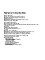
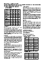
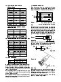
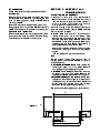
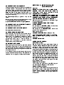
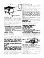
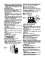
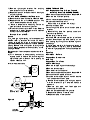
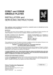
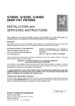
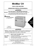
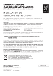
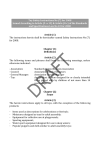
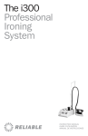
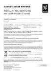
GAS CHIEFTAIN RANGES,
BOILING TABLES and OVENS
INSTALLATION and
SERVICING INSTRUCTIONS
These appliances must be installed and serviced by a competent person as stipulated by the Gas
Safety (Installation & Use) Regulations.
IMPORTANT
The installer must ensure that the installation of the appliance is in conformity with these instructions and
National Regulations in force at the time of installation. Particular attention MUST be paid to -
Gas Safety (Installation & Use) Regulations
Health And Safety At Work etc. Act
Local and National Building Regulations
Fire Precautions Act
Detailed recommendations are contained in
Institute of Gas Engineers published
documents :
IGE/ UP/ 1, IGE/ UP/ 2
BS6173 and BS5440
These appliances have been CE-marked on the basis of compliance with the Gas Appliance Directive for the
Countries, Gas Types and Pressures as stated on the data plate.
WARNING - TO PREVENT SHOCKS, ALL APPLIANCES WHETHER
GAS OR ELECTRIC, MUST BE EARTHED
On completion of the installation, these instructions should be left with the Engineer-in-Charge for reference
during servicing. Further to this, the Users Instructions should be handed over to the User, having had a
demonstration of the operation and cleaning of the appliance.
IT IS MOST IMPORTANT THAT THESE INSTRUCTIONS BE CONSULTED BEFORE INSTALLING AND
COMMISSIONING THIS APPLIANCE. FAILURE TO COMPLY WITH THE SPECIFIED PROCEDURES MAY
RESULT IN DAMAGE OR THE NEED FOR A SERVICE CALL.
PREVENTATIVE MAINTENANCE CONTRACT
In order to obtain maximum performance from this unit we would recommend that a maintenance contract be
arranged with SERVICELINE. Visits may then be made at agreed intervals to carry out adjustments and
repairs. A quotation will be given upon request to the contact numbers below.
At end of unit life, dispose of appliance and any replacement parts in a safe manner, via a licenced waste
handler. Units are designed to be dismantled easily and recycling of all material is encouraged whenever
practicable.
WEEE Directive Registration No. WEE/DC0059TT/PRO
At end of unit life, dispose of appliance and any replacement parts
in a safe manner, via a licenced waste handler.
Units are designed to be dismantled easily and recycling of all
material is encouraged whenever practicable.
Falcon Foodservice Equipment
HEAD OFFICE AND WORKS
Wallace View, Hillfoots Road, Stirling. FK9 5PY. Scotland.
SERVICELINE CONTACT -
PHONE - 01438 363 000 FAX - 01438 369 900
T100628 Ref. 3
Warranty Policy Shortlist
Warranty does not cover :Correcting faults caused by incorrect installation of a product.
Where an engineer cannot gain access to a site or a product.
Repeat commission visits.
Replacement of any parts where damage has been caused by misuse.
Engineer waiting time will be chargeable.
Routine maintenance and cleaning.
Gas conversions i.e. Natural to Propane gas.
Descaling of water products and cleaning of water sensors where softeners/conditioners are not fitted,
or are fitted and not maintained.
Blocked drains.
Independent steam generation systems.
Gas, water and electrical supply external to unit.
Light bulbs.
Re-installing vacuum in kettle jackets.
Replacement of grill burner ceramics when damage has been clearly caused by misuse.
Where an engineer finds no fault with a product that has been reported faulty.
Re-setting or adjustment of thermostats when unit is operating to specification.
Cleaning and unblocking of fryer filter systems due to customer misuse.
Lubrication and adjustment of door catches.
Cleaning and Maintenance:
Cleaning of burner jets
Poor combustion caused by lack of cleaning
Lubrication of moving parts
Lubrication of gas cocks
Cleaning/adjustment of pilots
Correction of gas pressure to appliance.
Renewing of electric cable ends
Replacement of fuses
Corrosion caused by use of chemical cleaners.
SECTION 1 - INSTALLATION
UNLESS OTHERWISE STATED, PARTS WHICH HAVE BEEN PROTECTED BY THE MANUFACTURER
ARE NOT TO BE ADJUSTED BY THE INSTALLER
1.1 MODEL NUMBERS, NETT WEIGHTS
and DIMENSIONS
Model
G1006X Open
Top Range
G1006BX Solid
Top Range
G1006FX Twin
Bullseye Range
G1016/1 Single
Tier Oven
G1016/2 Double
Tier Oven
G1026X Open
Top Boiling Table
G1026BX Solid
Top Boiling Table
G1060X
Boiling Table
G1066X
Open Top Range
Width
mm
Depth
mm
Height Weight
mm
kg
900
940
890
240
900
940
890
245
900
940
890
253
900
940
890
176.5
900
940
1740
353
900
940
890
141
900
940
890
159
900
940
890
159
900
940
890
255
1.2 SITING
The unit must be installed on a firm level,
non-combustible floor in a well lit position.
All models should have a 150mm minimum clearance
all round from any combustible wall and 150mm from
any non-combustible side wall to allow removal of the
side panels. There should be a minimum vertical
clearance of 1220mm above the top edge of range
and boiling table flues.
Important
If the appliance is to be installed in suite formation
with other matching appliances, the instructions for all
units must be consulted to determine the necessary
clearance to any combustible rear wall or overlying
surface. Some units require greater clearances than
others. The largest figure quoted in the individual
instructions will therefore determine the clearance for
the complete suite of adjoining appliances.
1.3 VENTILATION
Adequate ventilation, whether natural or mechanical,
must be provided to supply sufficient fresh air for
combustion and for removal of combustion products,
which may be harmful to health.
Recommendations for ventilation for catering
appliances are given in BS 5440:2. For multiple
installations, requirements for individual units should
be added together.
Installation should be made in accordance with local
and/or national regulations applying at the time.
A competent installer must be employed.
A direct connection MUST NOT be made to an
extract fan system or to the open air. Flues are best
discharged under a canopy connecting with a
ventilating system.
1.4 GAS SUPPLY
The incoming service must be of sufficient size to
supply full rate without excessive pressure drop.
A gas meter is connected to the service pipe by the
Gas Supplier. An existing meter should be checked,
preferably by the Gas Supplier to ensure it is of
adequate capacity to supply the unit and other
associated equipment.
Installation pipework should be fitted in accordance
with IGE/UP/2. The size of the pipework from the
meter system to the appliance must be not less than
that of the inlet connection. R3/4 (3/4" BSP female)
with regulator for Natural Gas and R1/2 (1/2" BSP
female) without regulator for Propane Models.
Important
Check for gas tightness.
An isolating cock must be located close to the
appliance and accessible to the user to allow
shutdown during an emergency or servicing.
The installation must be purged and tested for gas
tightness, details are given in IGE/UP/1.
The adjustable governor supplied must be fitted to
natural gas appliances in an accessible and spillage
free position and downstream of the isolating cock.
1.5 ELECTRICAL SUPPLY
Not applicable to this appliance.
1.6 WATER SUPPLY
Not applicable to this appliance.
1.7 TOTAL RATED HEAT INPUTS NATURAL GAS
Model
G1006X O/T
G1006BX S/T
G1006FX T/B
G1016/1
G1016/2
G1026X O/T
G1026BX S/T
G1060X O/T
G1066X O/T
kW (net)
Btu/hr (gross)
40
19.5
25
10
20
30
9.5
45
55
150,100
73,000
94,000
37,500
75,000
112,500
35,600
169,000
206,500
INDIVIDUAL BURNER HEAT INPUTS NATURAL GAS
Configuration
kW (net)
Btu/hr (gross)
Open Top
7.5
28,100
Solid Top
9.5
35,600
Twin Bullseye
7.5
28,100
Oven
10
37,500
1.8 TOTAL RATED HEAT INPUTS PROPANE GAS
Model
G1006X O/T
G1006BX S/T
G1006FX T/B
G1016/1
G1016/2
G1026X O/T
G1026BX S/T
G1060X O/T
G1066X O/T
kW (net)
Btu/hr (gross)
40
19.5
21
10
20
30
9.5
45
55
150,100
73,000
78,800
37,500
75,000
112,500
35,600
169,000
206,500
INDIVIDUAL BURNER HEAT INPUTS PROPANE GAS
Configuration
kW (net)
Btu/hr (gross)
Open Top
7.5
28,100
Solid Top
9.5
35,600
Twin Bullseye
5.5
20,600
Oven
10
37,500
1.9 INJECTOR SIZES - Natural and Propane Gas
Configuration
Open Top
Solid Top
Twin Bullseye
Oven
Natural Gas Propane Gas
é 2.3mm
é 1.4mm
é 2.6mm
Amal 360
6x é1.4mm 6x é0.66mm
é 2.6mm
Amal 360
1.11 BURNER AERATION
Fixed injectors are fitted and no means of adjusting
the full gas rate is provided. After setting working
pressure as Section 1.10. Check burner aeration.
X
Figure 1
Oven
An aeration shroud is located close to the injector at
the end of the oven burner. Check that aperture
dimension areas shown in Figure 1. This will achieve
desired cone length. If the burner is over-aerated, the
flame may extinguish at low rates. The correct full
rate cone lengths for natural gas is 25mm. Slightly
yellow flame tips are acceptable on propane units.
Figure 2
Open Top
Natural
Propane
mbar
15
37
inches w.g.
6
14.8
A test point is located on the manifold, behind control
panel. Solid top, single and double tier oven model
access is gained by removing the panel as described
in Section 3. Access on open top models is gained by
removing top facia panel.
An adjustable governor is supplied for natural gas
units. Propane unit pressure is controlled by the
incoming supply regulator.
For multiple burner natural gas units, set pressure at
15 mbar with approximately half the total heat input of
the appliance in operation.
10.5 - 11mm
Check aperture dimension for natural and propane
gas is as detailed in Figure 2. Check that flame is
stable and there is no evidence of flame lift.
0mm
PILOT BURNERS
Oven
SIT No. 36 SIT No. 19
Twin Bullseye
G29.2
G24.1
Solid Top
N26
L11
1.10 GAS PRESSURE
'X' gap on Natural Gas models - 5mm
'X' gap on Propane Gas models - Fully Open
Figure 3A
Figure 3B
7.5mm (+/- 1mm)
Solid Top
Check aeration shroud is located in position shown in
Figure 3A. There should be no flame lift or lightback.
Flames should be blue although slight yellow tipping
is acceptable for propane operation.
Injector should be located centrally within burner
venturi as detailed in Figure 3B.
SECTION 2 - ASSEMBLY and
COMMISSIONING
BY-PASS RATES
These are pre-set. To check, proceed as follows:-
Oven Burner
2.1 POSITIONING and ASSEMBLY
Remove vertical control panel and open lower front
panel as detailed in Section 3. Light burner and heat
oven for 45 minutes at a setting of 275oC before
reducing to 125oC.
Check flame lengths are approximately 5mm long.
Check setting by turning knob to 275oC and back to
125oC. The flame should reduce but not extinguish.
1. Position unit and level using feet adjusters.
Each foot contains a hole to enable floor fixing if
required. Units with castors must be installed in
such a manner that takes into account
manipulation and the restrictions on site.
If an oven or range is required to be mounted upon a
plinth, the areas indicated in Figure 4 MUST be kept
clear for aeration purposes.
2. Ovens: Open oven door, pull out shelves and
remove shelf runner. Lift up from bottom, ease
bottom outward and lower to free top fixing. Lift out
stainless steel base plates. Remove sheet metal
base baffle, lift and slide to one side. Rest this on
support angle top edge. Raise opposite end to
clear side baffle and remove from oven.
Check cast iron baffle plates are correctly located
over burner, resting on front and rear sloping
angles.
The two plates should touch at the centre.
Open and Solid Top Burners
Check flame lengths reduce to approximately 5mm
when gas control knob is turned to low flame setting.
The flame should reduce but not extinguish.
Note
The top surface of each plate has one lifting lug
directed toward oven centre. Replace all parts in
reverse sequence.
3. G1006BX/G1026BX Solid Top : Check by
removing bullseye, ring, filling plates. Remove
any loose packing and replace fillings etc.
4. G1006FX Twin Bullseye: Check by removing
bullseyes, rings and filling plates. Remove any
loose packing before replacement of fillings, etc.
5. G1006X/G1066X Open Top Models: Check open
top section, remove pan supports, all packing and
the tape securing burner components. Check that
burner caps and spillage trays are correctly
positioned before replacing pan supports.
6. A pot rack may be supplied as an optional extra.
894
Figure 4
680
185
60
140
15
257
317
829
879
200
2.2 CONNECTION TO A GAS SUPPLY
The gas supply piping and connection to appliance
must be installed in accordance with the various
regulations listed on the cover of this document.
On natural gas appliances, the adjustable governor
MUST be fitted to the supply, securely fixed in a
position which will enable adjustments to be made
during commissioning.
On propane appliances, a governor must not be
fitted.
Ensure isolating isolating cock is fitted close to range
in an accessible and spillage free position.
Important: Check installation for gas tightness.
2.3 CONNECTION TO AN ELECTRICITY SUPPLY
Not applicable to these models.
2.4 CONNECTION TO A WATER SUPPLY
Not applicable to these models.
2.5 PRE-COMMISSIONING CHECK
After installation, the engineer should check that all
gas connections are gas tight and do not leak.
Check that unit is operating satisfactorily before
leaving the kitchen. Burner and gas valve
adjustments should be in line with details in
Section 1.11. If adjustment is required, then the
appliance requires to be serviced.
2.6 INSTRUCTION TO USER
After installing and commissioning appliance, please
hand User Instructions to user or purchaser and
ensure that the person(s) responsible understands
the instructions for lighting, turning off and correct use
and care of the unit.
It is important to ensure that the gas isolating cock
location is made known to the user. The procedure for
operation in an emergency must be demonstrated.
SECTION 3 - SERVICING AND
CONVERSION
Important
BEFORE ATTEMPTING ANY SERVICING,
ENSURE THAT THE ISOLATING COCK IS
TURNED OFF AND CANNOT BE
INADVERTANTLY TURNED ON.
AFTER ANY MAINTENANCE TASK, CHECK THE
APPLIANCE TO ENSURE THAT IT PERFORMS
CORRECTLY AND CARRY OUT ANY NECESSARY
ADJUSTMENTS AS DETAILED IN SECTION 1.
After carrying out any servicing or exchange of gas
carrying components -
ALWAYS CHECK FOR GAS TIGHTNESS!
3.1 CONVERSION
For conversion to NATURAL GAS, fit the correct
governor and set the burner pressure.
For conversion to PROPANE GAS, remove the
governor from the gas circuit.
Other considerations CHANGE INJECTORS (Refer to Section 1.9)
ADJUST BYPASS SCREW TO SET LOW RATES
(Refer to Section 3.8) in gas taps and any oven
thermostat.
CHANGE DATA PLATE
3.2 REMOVAL OF PANELS
3.2.1 RH Outer Panel
Remove fixings which secure panel bottom flange to
underside of base. Slide panel back to withdraw two
pins which locate rear of vertical control panel.
Pull panel out slightly at bottom then draw it down
to clear top flange which engages under hob edge lip.
To replace, the stainless steel outer panels are fitted
between hob and base of unit approximately 25mm to
rear of their final position. Both panels are then slid
forward into position, the RH one to engage its
locating pins into the slots in the rear of vertical
control panels and LH to align flush with front frame.
The fixings (2 off) engage the bottom flange of the
side panels up through holes in the edge of the base
panel (see Figure 5).
3.2.2 Bottom Front Panel
Lift to unhook and lower. Undo lower RH hinge pin
and remove panel. Replace in reverse order.
3.2.3 Vertical Control Panel
Pull off control knobs. Remove fixings which secure
panel bottom flange to base plate. Withdraw panel
outward slightly at bottom to clear control spindles
and pull it down to free top locating flange. Replace in
reverse order.
Solid Tops (Single & Twin)
Figure 5
Locating Pins
Fixing screw with washers
3.2.4 Top Facia Panel
To remove control panel, remove control knobs and
pull panel toward front of unit to unclip. To replace,
line bullets up with clips and push until you hear a
click.
3.2.5 Oven Door
a) Remove control panel as detailed in Section 3.2.3.
b) Unhook bottom front panel and lower down.
c) Close oven door.
d) Using a screwdriver for leverage, unhook door
quadrant springs. Support door to prevent
accidental opening whilst removing springs. Open
door approximately three quarters of its travel and
lift slightly to clear hinge pins.
Pull forward to allow quadrants to slide through the
front frame apertures.
e) Replace in reverse order.
3.3 BURNER and INJECTORS
Note
Burners and injectors should be cleaned periodically
to maintain maximum performance. Burners are best
cleaned with a wire brush and washed, drilled ports
freed from blockage with a metal broach, and loose
material being shaken out via the burner shank.
Injectors are best cleaned with a wooden splinter or
soft fuse wire, metal reamers may distort or increase
the orifice size and must not be used.
Ensure that burners are dry and free from any
cleaning material before replacing. Check adjustment
as in Section 1.
Open Top
R e mo v e p a n s u p p o r t s a n d bu r ne r h e a d
components. Injectors are removed by undoing the
compression joint between gas pipe and injector
holder. Undo injector grubscrew inside burner
assembly. Withdraw injector and holder from burner
inlet. Replace in reverse order. Ensure injector holder
is fitted fully forward in the burner assembly.
Aeration should be as detailed in Section 1.11.
Lock aeration screw after any adjustment.
Remove bullseyes, rings and hob fillings.
Clean burners using a wooden splinter or fuse wire
as detailed above.
Replace in reverse order.
Ensure aeration is set as detailed in Section 1.11.
After any adjustment, lock shroud in position.
Oven
Open bottom front panel and oven door. Lift out oven
shelves and shelf supports. Remove base plates and
baffle tray (lift up one end and rest on edge on
support angle, slide sideways then lift other end to
clear side angle supports). Remove cast iron heat
shields.
Disconnect thermocouple, electrode and pilot gas
supply from pilot burner.
Undo fixings which secure front end of burner to base
and slide burner rearwards from injector and retaining
bracket on base.
Replace in reverse order.
Ensure aeration is set as detailed in Section 1.11.
Lock aeration screw after any adjustment.
3.4 REMOVAL OF THERMOCOUPLE/
FLAME FAILURE DEVICE
3.4.1 Open Top Thermocouple
a) Remove pan support
b) Disconnect thermocouple nut at FFD.
c) Undo nut which secures thermocouple head to
mounting bracket and withdraw.
d) Replace in reverse order. Position thermocouple
head as indicated in Figure 6. Ensure FFD nut is
not overtightened. A quarter-turn past hand tight is
sufficient to prevent fracture of electrical point.
e) Replace all parts in reverse order.
5mm
Figure 6
63mm
3.4.2 Oven Flame Failure Device/Gas Cock
a) Remove vertical control panel and RH outer panel
as described in Sections 3.2.3 & 3.2.1.
b) Undo pilot supply pipe compression nut. Ease pipe
forward and clear.
c) Undo two compression nuts on control inlet and
outlet pipes.
d) Remove fixings which secures Z bracket support.
Partly withdraw control.
e) Undo thermocouple nut.
f) Remove Z bracket and fit it on new control.
g) Replace all parts in reverse order. Check gas joints
for gas tightness. Adjust by-pass screw to achieve
a flame cone height of approx. 5mm. Check flame
stability by turning control knob between high and
low flame operation.
3.4.3 Oven Thermocouple
a) Remove vertical control panel and RH outer panel
as described in Sections 3.2.3 and 3.2.1.
b) Undo thermocouple nut at FFD rear after partially
removing control.
c) Open bottom front panel and disconnect nut which
secures thermocouple head to pilot assembly and
withdraw.
d) Fit new thermocouple. Ensure the head is pushed
firmly into position before tightening nut and that
the FFD nut is not overtightened.
A quarter turn past hand tight must only be
employed to prevent fracture of this electrical joint.
e) Replace panels in reverse order.
3.4.4 Solid Top Flame Failure Device/Gas Cock
a) Remove control panel. See Section 3.2.4.
b) Remove solid top hob fillings.
c) Undo both large compression nuts on inlet and
outlet pipes.
d) Disconnect thermocouple nut.
e) Undo pilot supply pipe on ignition flame supply
pipe.
f) Undo fixings that secure control fixing plate to
bracket.
g) Remove fixing plate from old control and secure it
to replacement.
h) Replace all parts in reverse order.
3.4.5 Solid Top Thermocouple
(G1006BX/G1026BX)
a) Remove bullseye rings and hob fillings.
b) Undo thermocouple to FFD nut.
c) Undo locknuts which secure thermocouple to
bracket. Withdraw thermocouple.
d) Replace in reverse order. Position thermocouple
tip, 38mm above base as shown in Figure 7.
15mm +/-1mm
Figure 7
3.4.6 Twin Bullseye (Thermocouple Replacement)
a) Remove bullseye rings and hob castings.
b) Remove burner centre support.
c) Remove burner controls cover panel.
d) Remove control panel as detailed in Section 3.2.4.
e) Remove burner closest to thermocouple for clear
access to thermocouple nut.
f) Undo thermocouple nut at gas control tap.
g) Remove thermocouple.
h) Replace in reverse order.
Thermocouple
Figure 8
Burner
(unscrew to
remove)
Burner jet
Pilot injector
3.5 OVEN PIEZO UNIT REMOVAL
a) Open bottom front panel.
b) Remove fixings that secure piezo unit bracket to
base plate. Partly withdraw piezo unit and pull
igniter lead off.
c) Remove existing piezo unit from fixing bracket and
fit replacement.
d) Attach igniter lead to replacement piezo before
positioning.
e) Replace panel in reverse order.
3.6 REMOVAL OF OVEN SPARK ELECTRODE
a) Open bottom front panel.
b) Remove thermocouple. See Section 3.4.3.
c) Undo nut that secures electrode lead.
d) Undo gland nut and withdraw electrode.
e) Replace in reverse order and ensure thermocouple
head is correctly positioned as detailed in Section
3.4.3. The electrode conductor terminal should be
clear of any adjacent metal parts.
3.7 THERMOSTAT
3.7.1 Oven Control Thermostat
a) Remove vertical control panel and RH outer panel.
(see Sections 3.2.3 and 3.2.1.)
b) Undo inlet and outlet pipes compression nuts.
c) Remove fixings that secure right-angled bracket to
Z bracket.
d) Open oven door and release phial by removing
clips which secure it to roof baffle.
e) Gently pull phial and capillary tube through oven
side hole and withdraw thermostat.
f) Remove right-angled bracket from existing
thermostat and fit it to replacement.
g) Replace all parts in reverse order and check gas
joints for tightness.
3.7.2 To Check and Adjust the Thermostat
a) Remove control panel as detailed in Section 3.2.3.
b) Replace knob and turn to 200oC position. This
should be the temperature at this setting.
c) Place a temperature measuring device at
geometric centre of oven and light oven.
d) Allow oven to heat up for 30 minutes. Observe
temperature is steady. Compare value obtained
with required value of 200oC.
Example - Oven at 190oC.
Action
Turn knob to a higher setting until a temperature of
200oC+/-5oC is obtained. Pull knob off without
rotating spindle. Undo fixings on adjusting flange at
spindle base. Replace knob and turn it back to 200oC
setting. Remove knob and tighten adjusting flange
fixings. Check temperature remains steady at new
setting for 200oC.
Reverse action if oven temperature is above or below
200oC.
e) Turn thermostat to lowest setting and adjust
by-pass screw to achieve flame cone length of
approximately 5mm. Check flame stability as
detailed in Section 1.11.
Oven thermostat bypass screw
Bypass screw
Pilot
(Solid Top Only)
Figure 9
Low flame
adjustment
3.8 GAS TAPS and FFD
3.8.1 Replacement Taps for Open Top and
Solid Top Burners (G1006BX/G1026BX)
a) Remove control panel as detailed in Section 3.2.4.
b) Remove hob lift-off components.
c) Undo inlet/outlet pipe compression nuts.
d) Disconnect thermocouple nut.
For solid top units, proceed with e) to g).
e) Undo pilot supply pipe.
f) Undo fixings that secure control location plate to
bracket.
g) Remove fixing plate from previous control and
secure to replacement.
Replace parts in reverse order.
Also check FFD thermocouple position at low flame
operation. Check open top flame stability on low
flame settings by turning control between high and
low settings.
To set by-pass rate: Aim for flame cone lengths of
approximately 5mm. Typically, this may be achieved
by withdrawing by-pass screw from its closed position
by:
Open Top
Natural Gas - Half turn
Propane Gas - Quarter turn
Solid Top
Propane Gas - Two Turns
3.8.2 Twin Bullseye
a) Remove bullseye rings and hob castings.
b) Remove centre support.
c) Remove burner control panel.
d) Remove control panel as detailed in Section 3.2.4.
e) Undo saddle clamp plate to float rail.
f) Unscrew burner assembly and manifold bracket
from side panel and crown plate.
g) Remove burner assembly c/w with gas tap and
manifold bracket to gain complete access to
pipework.
h) Remove pilot pipe, main feed pipe and
thermocouple nut from tap.
j) Remove pilot pipe adaptor from gas tap.
k) Replace components in reverse order.
m) Replace all parts in reverse order.
3.8.3 Gas Taps (Cleaning & Greasing)
Note
Plugs and bodies are machined as matching pairs
and are non-interchangeable. To avoid mix-up, clean
one tap at a time.
a) Remove top facia panel (see Section 3.2.4).
b) Remove fixings from tap body front. Withdraw
spindle and niting arrangement to allow plug to be
eased out.
c) Clean plug and body with a soft rag and re-grease
with an approved high temperature lubricant.
Apply grease sparingly, DO NOT block the gas
passageways of plug and body.
d) Ensure that plug is inserted into body in correct
position for operation.
e) Secure end cap to body. Note that fixing holes line
up in one way only.
3.9 GOVERNOR (Natural Gas Appliances Only)
The type of governor supplied is maintenance-free.
Check that blue dust cap covering vent is fitted and in
good condition as this protects the breather hole.
SECTION 4 - SPARE PARTS
When ordering spares, always quote unit type and
serial number. This information can be found on the
data plate, attached to the appliance.