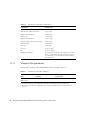
1
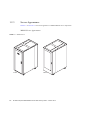
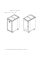
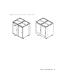
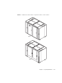
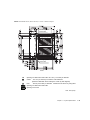
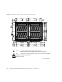
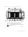
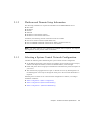
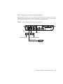
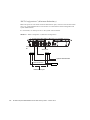
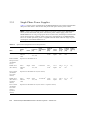
SPARC Enterprise
M8000/M9000 Servers
Site Planning Guide
Part No.: E23589-03
Manual Code: C120-H014-11EN
October 2012
Copyright © 2007, 2012, Fujitsu Limited. All rights reserved.
Oracle and/or its affiliates provided technical input and review on portions of this material.
Oracle and/or its affiliates and Fujitsu Limited each own or control intellectual property rights relating to products and technology described in this document, and such
products, technology and this document are protected by copyright laws, patents, and other intellectual property laws and international treaties.
This document and the product and technology to which it pertains are distributed under licenses restricting their use, copying, distribution, and decompilation. No part of
such product or technology, or of this document, may be reproduced in any form by any means without prior written authorization of Oracle and/or its affiliates and Fujitsu
Limited, and their applicable licensors, if any. The furnishings of this document to you does not give you any rights or licenses, express or implied, with respect to the
product or technology to which it pertains, and this document does not contain or represent any commitment of any kind on the part of Oracle or Fujitsu Limited, or any
affiliate of either of them.
This document and the product and technology described in this document may incorporate third-party intellectual property copyrighted by and/or licensed from the
suppliers to Oracle and/or its affiliates and Fujitsu Limited, including software and font technology.
Per the terms of the GPL or LGPL, a copy of the source code governed by the GPL or LGPL, as applicable, is available upon request by the End User. Please contact
Oracle and/or its affiliates or Fujitsu Limited.
This distribution may include materials developed by third parties.
Parts of the product may be derived from Berkeley BSD systems, licensed from the University of California. UNIX is a registered trademark in the U.S. and in other
countries, exclusively licensed through X/Open Company, Ltd.
Oracle and Java are registered trademarks of Oracle and/or its affiliates. Fujitsu and the Fujitsu logo are registered trademarks of Fujitsu Limited.
All SPARC trademarks are used under license and are registered trademarks of SPARC International, Inc. in the U.S. and other countries. Products bearing SPARC
trademarks are based upon architectures developed by Oracle and/or its affiliates. SPARC64 is a trademark of SPARC International, Inc., used under license by Fujitsu
Microelectronics, Inc. and Fujitsu Limited. Other names may be trademarks of their respective owners.
United States Government Rights - Commercial use. U.S. Government users are subject to the standard government user license agreements of Oracle and/or its affiliates
and Fujitsu Limited and the applicable provisions of the FAR and its supplements.
Disclaimer: The only warranties granted by Oracle and Fujitsu Limited, and/or any affiliate of either of them in connection with this document or any product or
technology described herein are those expressly set forth in the license agreement pursuant to which the product or technology is provided. EXCEPT AS EXPRESSLY
SET FORTH IN SUCH AGREEMENT, ORACLE OR FUJITSU LIMITED, AND/OR THEIR AFFILIATES MAKE NO REPRESENTATIONS OR WARRANTIES OF
ANY KIND (EXPRESS OR IMPLIED) REGARDING SUCH PRODUCT OR TECHNOLOGY OR THIS DOCUMENT, WHICH ARE ALL PROVIDED AS IS, AND
ALL EXPRESS OR IMPLIED CONDITIONS, REPRESENTATIONS AND WARRANTIES, INCLUDING WITHOUT LIMITATION ANY IMPLIED WARRANTY
OF MERCHANTABILITY, FITNESS FOR A PARTICULAR PURPOSE OR NON-INFRINGEMENT, ARE DISCLAIMED, EXCEPT TO THE EXTENT THAT
SUCH DISCLAIMERS ARE HELD TO BE LEGALLY INVALID. Unless otherwise expressly set forth in such agreement, to the extent allowed by applicable law, in no
event shall Oracle or Fujitsu Limited, and/or any of their affiliates have any liability to any third party under any legal theory for any loss of revenues or profits, loss of use
or data, or business interruptions, or for any indirect, special, incidental or consequential damages, even if advised of the possibility of such damages.
DOCUMENTATION IS PROVIDED “AS IS” AND ALL EXPRESS OR IMPLIED CONDITIONS, REPRESENTATIONS AND WARRANTIES, INCLUDING ANY
IMPLIED WARRANTY OF MERCHANTABILITY, FITNESS FOR A PARTICULAR PURPOSE OR NON-INFRINGEMENT, ARE DISCLAIMED, EXCEPT TO
THE EXTENT THAT SUCH DISCLAIMERS ARE HELD TO BE LEGALLY INVALID.
Please
Recycle
Copyright © 2007, 2012, Fujitsu Limited. Tous droits réservés.
Oracle et/ou ses sociétés affiliées ont fourni et vérifié des données techniques de certaines parties de ce composant.
Oracle et/ou ses sociétés affiliées et Fujitsu Limited détiennent et contrôlent chacune des droits de propriété intellectuelle relatifs aux produits et technologies décrits dans
ce document. De même, ces produits, technologies et ce document sont protégés par des lois sur le copyright, des brevets, d’autres lois sur la propriété intellectuelle et des
traités internationaux.
Ce document, le produit et les technologies afférents sont exclusivement distribués avec des licences qui en restreignent l’utilisation, la copie, la distribution et la
décompilation. Aucune partie de ce produit, de ces technologies ou de ce document ne peut être reproduite sous quelque forme que ce soit, par quelque moyen que ce soit,
sans l’autorisation écrite préalable d’Oracle et/ou ses sociétés affiliées et de Fujitsu Limited, et de leurs éventuels bailleurs de licence. Ce document, bien qu’il vous ait été
fourni, ne vous confère aucun droit et aucune licence, expresses ou tacites, concernant le produit ou la technologie auxquels il se rapporte. Par ailleurs, il ne contient ni ne
représente aucun engagement, de quelque type que ce soit, de la part d’Oracle ou de Fujitsu Limited, ou des sociétés affiliées de l’une ou l’autre entité.
Ce document, ainsi que les produits et technologies qu’il décrit, peuvent inclure des droits de propriété intellectuelle de parties tierces protégés par copyright et/ou cédés
sous licence par des fournisseurs à Oracle et/ou ses sociétés affiliées et Fujitsu Limited, y compris des logiciels et des technologies relatives aux polices de caractères.
Conformément aux conditions de la licence GPL ou LGPL, une copie du code source régi par la licence GPL ou LGPL, selon le cas, est disponible sur demande par
l’Utilisateur final. Veuillez contacter Oracle et/ou ses sociétés affiliées ou Fujitsu Limited.
Cette distribution peut comprendre des composants développés par des parties tierces.
Des parties de ce produit peuvent être dérivées des systèmes Berkeley BSD, distribués sous licence par l’Université de Californie. UNIX est une marque déposée aux
États-Unis et dans d’autres pays, distribuée exclusivement sous licence par X/Open Company, Ltd.
Oracle et Java sont des marques déposées d’Oracle Corporation et/ou de ses sociétés affiliées. Fujitsu et le logo Fujitsu sont des marques déposées de Fujitsu Limited.
Toutes les marques SPARC sont utilisées sous licence et sont des marques déposées de SPARC International, Inc., aux États-Unis et dans d’autres pays. Les produits
portant la marque SPARC reposent sur des architectures développées par Oracle et/ou ses sociétés affiliées. SPARC64 est une marque de SPARC International, Inc.,
utilisée sous licence par Fujitsu Microelectronics, Inc. et Fujitsu Limited. Tout autre nom mentionné peut correspondre à des marques appartenant à d’autres propriétaires.
United States Government Rights - Commercial use. U.S. Government users are subject to the standard government user license agreements of Oracle and/or its affiliates
and Fujitsu Limited and the applicable provisions of the FAR and its supplements.
Avis de non-responsabilité : les seules garanties octroyées par Oracle et Fujitsu Limited et/ou toute société affiliée de l’une ou l’autre entité en rapport avec ce document
ou tout produit ou toute technologie décrits dans les présentes correspondent aux garanties expressément stipulées dans le contrat de licence régissant le produit ou la
technologie fournis. SAUF MENTION CONTRAIRE EXPRESSÉMENT STIPULÉE DANS CE CONTRAT, ORACLE OU FUJITSU LIMITED ET LES SOCIÉTÉS
AFFILIÉES À L’UNE OU L’AUTRE ENTITÉ REJETTENT TOUTE REPRÉSENTATION OU TOUTE GARANTIE, QUELLE QU’EN SOIT LA NATURE
(EXPRESSE OU IMPLICITE) CONCERNANT CE PRODUIT, CETTE TECHNOLOGIE OU CE DOCUMENT, LESQUELS SONT FOURNIS EN L’ÉTAT. EN
OUTRE, TOUTES LES CONDITIONS, REPRÉSENTATIONS ET GARANTIES EXPRESSES OU TACITES, Y COMPRIS NOTAMMENT TOUTE GARANTIE
IMPLICITE RELATIVE À LA QUALITÉ MARCHANDE, À L’APTITUDE À UNE UTILISATION PARTICULIÈRE OU À L’ABSENCE DE CONTREFAÇON,
SONT EXCLUES, DANS LA MESURE AUTORISÉE PAR LA LOI APPLICABLE. Sauf mention contraire expressément stipulée dans ce contrat, dans la mesure
autorisée par la loi applicable, en aucun cas Oracle ou Fujitsu Limited et/ou l’une ou l’autre de leurs sociétés affiliées ne sauraient être tenues responsables envers une
quelconque partie tierce, sous quelque théorie juridique que ce soit, de tout manque à gagner ou de perte de profit, de problèmes d’utilisation ou de perte de données, ou
d’interruptions d’activités, ou de tout dommage indirect, spécial, secondaire ou consécutif, même si ces entités ont été préalablement informées d’une telle éventualité.
LA DOCUMENTATION EST FOURNIE « EN L’ÉTAT » ET TOUTE AUTRE CONDITION, DÉCLARATION ET GARANTIE, EXPRESSE OU TACITE, EST
FORMELLEMENT EXCLUE, DANS LA MESURE AUTORISÉE PAR LA LOI EN VIGUEUR, Y COMPRIS NOTAMMENT TOUTE GARANTIE IMPLICITE
RELATIVE À LA QUALITÉ MARCHANDE, À L’APTITUDE À UNE UTILISATION PARTICULIÈRE OU À L’ABSENCE DE CONTREFAÇON.
Contents
Preface
1.
vii
Physical Specification
1.1
Before Setting Up the System
1.2
Physical Specifications
1–4
Server Components
1.2.2
External Dimensions and Weights
1.2.3
Server Appearance
1.2.4
Server Installation (Space)
1–4
1–4
1–6
1–12
1.2.4.1
Size and Space Specifications
1.2.4.2
Footprints of the Cabinets
1.2.4.3
Free-Access Floor Openings for Underfloor Air
Conditioning 1–28
1.2.4.4
Ceiling Height
Access Route
1–12
1–21
1–30
1–31
Network Connection Specifications
2.1
1–1
1.2.1
1.2.5
2.
1–1
2–1
Planning Your Network Connection
2–1
2.1.1
Setup and Network Connections
2–2
2.1.2
Platform and Domain Setup Information
2.1.3
Selecting a System Control Network Configuration
2–3
2–3
v
2.2
3.
UPS Controller
2.2.1
Overview
2–7
2.2.2
Signal Cables
2.2.3
Signal Line Configuration
2.2.4
Cable Connector
2–7
2–8
2–10
Environmental and Electrical Specifications
3.1
3.2
3.3
Environmental Requirements
Index
3–1
3–1
3.1.1
Ambient Environmental Requirements
3.1.2
Recommended Ambient Temperature and Humidity
3.1.3
Contamination Specifications
3.1.4
Vibration Requirements
Cooling Specifications
3–1
3–4
3–5
Cooling (Air-Conditioning) Requirements
3.2.2
Airflow and Heat Dissipation
3.2.3
Airflow Indicator
Electrical Specifications
3–2
3–3
3.2.1
3–5
3–5
3–8
3–8
3.3.1
Single-Phase Power Supplies
3.3.2
Three-Phase Power Delta Supplies
3.3.3
Three-Phase Star Power Supplies
3.3.4
Circuit Breaker Capacity and Characteristics
3.3.5
Grounding
3.3.6
CPU Types and Server Maximum Power Consumption
Abbreviations
vi
2–7
3–10
3–16
3–20
3–23
3–25
Abbreviations–1
Index–1
SPARC Enterprise M8000/M9000 Servers Site Planning Guide • October 2012
3–25
Preface
This site planning guide describes the physical, environmental, and electrical specification
requirements of the SPARC Enterprise M8000/M9000 servers from Oracle and Fujitsu.
References herein to the M8000 server or M9000 server are references to the SPARC
Enterprise M8000 or SPARC Enterprise M9000 server.
This chapter includes the following sections:
■
“Audience” on page vii
■
“Related Documentation” on page viii
■
“Text Conventions” on page ix
■
“Notes on Safety” on page ix
■
“Syntax of the Command-Line Interface (CLI)” on page x
■
“Documentation Feedback” on page x
Audience
This guide is written for experienced system administrators with working knowledge of
computer networks and advanced knowledge of the Oracle Solaris Operating System (Oracle
Solaris OS).
vii
Related Documentation
All documents for your sever are available online at the following locations:
Documentation
Link
Sun Oracle software-related manuals
(Oracle Solaris OS, and so on)
http://www.oracle.com/documentation
Fujitsu documents
http://www.fujitsu.com/sparcenterprise/manual/
Oracle M-series server documents
http://www.oracle.com/technetwork/documentation/spa
rc-mseries-servers-252709.html
The following table lists titles of related documents.
Related SPARC Enterprise M8000/M9000 Servers Documents
SPARC Enterprise M8000/M9000 Servers Site Planning Guide
SPARC Enterprise M8000/M9000 Servers Getting Started Guide*
SPARC Enterprise M8000/M9000 Servers Overview Guide
SPARC Enterprise M3000/M4000/M5000/M8000/M9000 Servers Important Legal and Safety Information *
SPARC Enterprise M8000/M9000 Servers Safety and Compliance Guide
External I/O Expansion Unit Safety and Compliance Guide
SPARC Enterprise M8000/M9000 Servers Unpacking Guide*
SPARC Enterprise M8000/M9000 Servers Installation Guide
SPARC Enterprise M8000/M9000 Servers Service Manual
External I/O Expansion Unit Installation and Service Manual
SPARC Enterprise M3000/M4000/M5000/M8000/M9000 Servers Administration Guide
SPARC Enterprise M3000/M4000/M5000/M8000/M9000 Servers XSCF User’s Guide
SPARC Enterprise M3000/M4000/M5000/M8000/M9000 Servers XSCF Reference Manual
SPARC Enterprise M4000/M5000/M8000/M9000 Servers Dynamic Reconfiguration (DR) User’s Guide
SPARC Enterprise M4000/M5000/M8000/M9000 Servers Capacity on Demand (COD) User’s Guide
SPARC Enterprise M3000/M4000/M5000/M8000/M9000 Servers Product Notes†
SPARC Enterprise M8000/M9000 Servers Product Notes
External I/O Expansion Unit Product Notes
SPARC Enterprise M3000/M4000/M5000/M8000/M9000 Servers Glossary
viii SPARC Enterprise M8000/M9000 Servers Site Planning Guide • October 2012
* This is a printed document.
† Beginning with the XCP 1100 release.
Text Conventions
This manual uses the following fonts and symbols to express specific types of information.
Font/Symbol
Meaning
Example
AaBbCc123
What you type, when contrasted with
on-screen computer output.
This font represents the example of
command input in the frame.
XSCF> adduser jsmith
AaBbCc123
The names of commands, files, and
directories; on-screen computer
output.
This font represents the example of
command output in the frame.
XSCF> showuser -P
User Name:
jsmith
Privileges: useradm
auditadm
Italic
Indicates the name of a reference
manual, a variable, or user-replaceable
text.
See the SPARC Enterprise
M3000/M4000/M5000/M8000/M9000
Servers XSCF User’s Guide.
""
Indicates names of chapters, sections,
items, buttons, or menus.
See Chapter 2, "System Features."
Notes on Safety
Read the following documents thoroughly before using or handling any SPARC Enterprise
M8000/M9000 server.
■
SPARC Enterprise M3000/M4000/M5000/M8000/M9000 Servers Important Legal and
Safety Information
■
SPARC Enterprise M8000/M9000 Servers Safety and Compliance Guide
Preface
ix
Syntax of the Command-Line Interface
(CLI)
The command syntax is as follows:
■
A variable that requires input of a value must be put in Italics.
■
An optional element must be enclosed in [].
■
A group of options for an optional keyword must be enclosed in [] and delimited by |.
Documentation Feedback
If you have any comments or requests regarding this document, go to the following websites:
■
For Oracle users:
http://www.oracle.com/goto/docfeedback
Include the title and part number of your document with your feedback:
SPARC Enterprise M8000/M9000 Servers Site Planning Guide,
part number E23589-02
■
For Fujitsu users:
http://www.fujitsu.com/global/contact/computing/sparce_index.html
x
SPARC Enterprise M8000/M9000 Servers Site Planning Guide • October 2012
C H A PT E R
1
Physical Specification
This chapter describes what the reader is expected to know, including physical specification
for the SPARC Enterprise M8000/M9000 servers, before planning server installation.
This chapter contains the following sections:
1.1
■
Section 1.1, “Before Setting Up the System” on page 1-1
■
Section 1.2, “Physical Specifications” on page 1-4
Before Setting Up the System
Before starting server installation, verify that the requirements listed in TABLE 1-1 are
satisfied.
TABLE 1-1
Checklist
Requirements
Item
Check
System components
Have the server components been decided?
❏
Has the total number of servers been decided?
❏
Have the system administrators and operators taken the necessary training
courses??
❏
System management
1-1
TABLE 1-1
Checklist (Continued)
Requirements
Item
Check
Physical specifications
Has the server installation location been decided?
❏
Does the installation floor layout satisfy the ventilation and maintenance access
requirements?
See Section 1.2.4, “Server Installation (Space)” on page 1-12
❏
Does the device layout guarantee that heated air vented from one device does
not enter an air intake of another device?
See Section 1.2.4, “Server Installation (Space)” on page 1-12
❏
Does the access route provide sufficient space for transport of the packed server
cabinets? Have you confirmed that all route incline angles are within the
permitted range?
See Section 1.2.5, “Access Route” on page 1-31
❏
If a pallet jack is to be used, have you confirmed that the cabinet weight is
within the load limit of the pallet jack?
See Section 1.2.5, “Access Route” on page 1-31
❏
If an elevator is to be used, have you confirmed that the elevator car is wide
enough for the cabinet to be carried into it and that the cabinet weight is within
the load limit of the elevator?
See Section 1.2.5, “Access Route” on page 1-31
❏
Network specification
Do you clearly understand what data connections and feeds are required for
system startup and network connections?
See CHAPTER 2, “Network Connection Specifications” on page 2-1
❏
Environmental specifications
Does the computer room air handling meet temperature and humidity
requirements?
See Section 3.1, “Environmental Requirements” on page 3-1
❏
Can the computer room continuously satisfy environmental requirements?
❏
Is the computer room adequately equipped to extinguish a fire?
❏
Is the computer room secured?
❏
Access route
1-2
SPARC Enterprise M8000/M9000 Servers Site Planning Guide • October 2012
TABLE 1-1
Checklist (Continued)
Requirements
Item
Check
Facility power
Do you know the required operating voltages and electrical current levels of the
server and peripherals?
See Section 3.3, “Electrical Specifications” on page 3-8
❏
Are enough power outlets provided for the server cabinet, monitors, and
peripherals?
❏
Are the circuit breakers for the server suitable in terms of voltage and currentcarrying capacities?
See Section 3.3, “Electrical Specifications” on page 3-8
❏
If you use single-phase power feed, is a power outlet located within 3.0 meters
(9.8 ft) of the server?
❏
Chapter 1
Physical Specification
1-3
1.2
Physical Specifications
This section outlines the M8000/M9000 server components and lists their physical
specifications.
1.2.1
Server Components
TABLE 1-2 lists the names, the capacities and functions of the M8000/M9000 server
components.
TABLE 1-2
Names and Quantities
Name
Capacity/Function
M8000 server
Accommodates up to four CMUs [up to 16 CPU modules:
(32 cores for SPARC64 VI processors, 64 cores for SPARC64
VII/SPARC64 VII+ processors)] and up to four IOUs.
M9000 server
(base cabinet)
Accommodates up to eight CMUs [up to 32 CPU modules:
(64 cores for SPARC64 VI processors, 128 cores for
SPARC64 VII/SPARC64 VII+ processors)] and up to eight
IOUs.
M9000 server
(expansion cabinet)
Accommodates up to eight CMUs [up to 32 CPU modules:
(64 cores for SPARC64 VI processors, 128 cores for
SPARC64 VII/SPARC64 VII+ processors)] and up to eight
IOUs.
Rack-mountable dual
power feed
Provides power redundancy (with single-phase dual power
feed) for an M8000 server.
Optional.
Power cabinet
There are two types of power cabinet:
• Provides three-phase dual power feed for an M8000 server
• Provides single-phase dual power feed or three-phase dual
power feed for an M9000 server
One power cabinet is required
for each M8000 server.
One power cabinet is required
for each M9000 server of the
base or expansion cabinet type.
(The single-phase dual power
feed for the M9000 server is
optional.)
1.2.2
Remarks
The M9000 server, when
combined with an expansion
cabinet can accommodate up to
16 CMUs [up to 64 CPU
modules: (128 cores for the
SPARC64 VI processor, 256
cores for the SPARC64 VII/
SPARC64 VII+ processors)] and
up to 16 IOUs.
External Dimensions and Weights
TABLE 1-3 lists the external dimensions and weights of the M8000/M9000 server cabinets.
1-4
SPARC Enterprise M8000/M9000 Servers Site Planning Guide • October 2012
TABLE 1-3
Installation Specifications (External Dimensions and Weights)
External Dimensions [mm (inch)]
Name
Width
Depth
Height
Weight [kg]
M8000 server
750 (29.5)
1260 (49.6)
1800 (70.9)
700**
M8000 + power cabinet
1054 (41.5)
1260 (49.6)
1800 (70.9)
1020**
M9000 server (base cabinet)
850 (33.5)
1260 (49.6)
1800 (70.9)
940
M9000 (base cabinet) + power cabinet
1154 (45.4)
1260 (49.6)
1800 (70.9)
1290
M9000 (base cabinet + expansion cabinet)
1674 (65.9)†
1260 (49.6)
1800 (70.9)
1880
M9000 (base cabinet + expansion cabinet) +
power cabinet
2282 (89.8)†
1260 (49.6)
1800 (70.9)
2580
Rack-mountable dual power feed*
489 (19.3)
1003 (39.5)
278 (10.9)
[6U]
75
Power cabinet
317 (12.5)‡
1244 (49.0)
1800 (70.9)
350
* The Rack-mountable dual power feed can only be mounted on the equipment rack.
† When combining a base cabinet and an expansion cabinet, the width of each cabinet is 837 mm (including the exterior side panels).
‡ The width of a power cabinet includes the exterior side panel.
**The weight of a server does not include the weight of optional hardware.
Chapter 1
Physical Specification
1-5
1.2.3
Server Appearance
FIGURE 1-1 to FIGURE 1-6 show each appearance of M8000/M9000 server components.
M8000 Server Appearance
FIGURE 1-1
M8000 Server
Front
1-6
Rear
SPARC Enterprise M8000/M9000 Servers Site Planning Guide • October 2012
FIGURE 1-2
M8000 Server + Power Cabinet
Front
Rear
Chapter 1
Physical Specification
1-7
M9000 Server Appearance
FIGURE 1-3
M9000 Server (Base Cabinet)
Front
1-8
Rear
SPARC Enterprise M8000/M9000 Servers Site Planning Guide • October 2012
FIGURE 1-4
M9000 Server (Base Cabinet + Expansion Cabinet)
Front
Rear
Chapter 1
Physical Specification
1-9
FIGURE 1-5
M9000 Server (Base Cabinet + Power Cabinet)
Rear
Front
1-10
SPARC Enterprise M8000/M9000 Servers Site Planning Guide • October 2012
FIGURE 1-6
M9000 Server (Base Cabinet + Expansion Cabinet + Power Cabinet)
Front
Rear
Chapter 1
Physical Specification
1-11
1.2.4
Server Installation (Space)
The M8000/M9000 server is intended to be used in a computer room.
1.2.4.1
Size and Space Specifications
Before beginning an M8000/M9000 server installation, secure a service area (maintenance
area) that is large enough for each cabinet plus required service access space for each
component. FIGURE 1-7 to FIGURE 1-16 show the space required for installation of each server.
M8000 Server Installation Area
FIGURE 1-7
M8000 Server Installation Area
1260 (49.6)
800 (31.5)
M8000
2860 (112.6)
800 (31.5)
Service area
Service area
750(29.5)
Unit: mm (inch)
Front
1-12
SPARC Enterprise M8000/M9000 Servers Site Planning Guide • October 2012
M8000 Server + Power Cabinet Installation Area
M8000
800 (31.5)
Power cabinet
800 (31.5)
Service area
1260 (49.6)
2860 (112.6)
FIGURE 1-8
Service area
1054 (41.5)
Unit: mm (inch)
Front
Note – Before mounting units in an M8000 server equipment rack, secure the service areas
as shown in FIGURE 1-9 or FIGURE 1-10.
Chapter 1
Physical Specification
1-13
FIGURE 1-9
M8000 Server (With an Equipment Rack) Installation Area
750 (29.5)
1260 (49.6)
M8000
2860 (112.6)
800 (31.5)
Service area
800 (31.5)
Service area
1550 (61.0)
Front
1-14
SPARC Enterprise M8000/M9000 Servers Site Planning Guide • October 2012
Unit: mm (inch)
FIGURE 1-10
M8000 Server (With an Equipment Rack) + Power Cabinet Installation Area
1054 (41.5)
2860 (112.6)
800 (31.5)
M8000
1260 (49.6)
Power cabinet
800 (31.5)
Service area
Service area
Unit: mm (inch)
1854 (73.0)
Front
Note – Before mounting units in an M8000 server equipment rack at a location where no
space can be secured on the right side of the server, secure the service areas as shown in
FIGURE 1-11 or FIGURE 1-12.
Chapter 1
Physical Specification
1-15
FIGURE 1-11
M8000 Server (With an Equipment Rack) Installation Area
1260 (49.6)
1200 (47.2)
M8000
3260 (128.3)
800 (31.5)
Service area
Service area
750 (29.5)
Front
1-16
SPARC Enterprise M8000/M9000 Servers Site Planning Guide • October 2012
Unit: mm (inch)
M8000 Server (With an Equipment Rack) + Power Cabinet Installation Area
1054 (41.5)
1200 (47.2)
3260 (128.3)
M8000
1260 (49.6)
Power cabinet
800 (31.5)
Service area
800 (31.5)
FIGURE 1-12
Service area
317
(12.5)
737 (29.0)
Unit: mm (inch)
Front
Chapter 1
Physical Specification
1-17
M9000 Server Installation Area
FIGURE 1-13
M9000 Server (Base Cabinet) Installation Area
1260 (49.6)
900 (35.4)
M9000
(Base cabinet)
3060 (128.3)
900 (35.4)
Service area
Service area
850 (33.4)
Unit: mm (inch)
Front
1-18
SPARC Enterprise M8000/M9000 Servers Site Planning Guide • October 2012
M9000 Server (Base Cabinet) + Power Cabinet Installation Area
1260 (49.6)
900 (35.4)
M9000
(Base cabinet)
3060 (128.3)
900 (35.4)
Service area
Power cabinet
FIGURE 1-14
317
(12.5)
Service area
837 (33.0)
1154 (45.3)
Unit: mm (inch)
Front
Chapter 1
Physical Specification
1-19
FIGURE 1-15
M9000 Server (Base Cabinet + Expansion Cabinet) Installation Area
3060 (128.3)
M9000
(Ex. cabinet)
900 (35.4)
M9000
(Base cabinet)
1260 (49.6)
900 (35.4)
Service area
Service area
837 (33.0)
Unit: mm (inch)
1674 (65.9)
Front
1-20
SPARC Enterprise M8000/M9000 Servers Site Planning Guide • October 2012
M9000 Server (Base Cabinet + Expansion Cabinet) + Power Cabinet Installation
Area
3060 (128.3)
M9000
(Ex. cabinet)
900 (35.4)
M9000
(Base cabinet)
Power cabinet
Power cabinet
900 (35.4)
Service area
1260 (49.6)
FIGURE 1-16
317
(12.5)
Service area
824 (32.4)
Unit: mm (inch)
2282 (89.8)
Front
1.2.4.2
Footprints of the Cabinets
FIGURE 1-17 to FIGURE 1-22 show the bottom of the M8000/M9000 server cabinets, such as
the openings for laying cables, air inlet ports used for cooling, legs, and casters. The views in
these figures are transparent (see-through) views of the bottom surface of the server as seen
from directly above the top of the server.
The values indicated are layout values of the cabinet. If its feet are fixed to the floor, size
difference (±2 mm/±0.08 inches) must be take into consideration to designate its location.
The bottom of the server is at about 90 mm (about 3.4 inches) from the floor surface.
Chapter 1
Physical Specification
1-21
M8000 Server Footprint
FIGURE 1-17
M8000 Server Footprint
Front
Caster : 113 mm (4.5 inches) in maximum outer diameter
(Maximum diameter when rotating the caster by 360 degrees)
Feet
: 66 mm (2.6 inches) in diameter Attached to the server by using M20
Opening for cables inlet and outlet
Opening for air inlet
Unit: mm (inch)
1-22
SPARC Enterprise M8000/M9000 Servers Site Planning Guide • October 2012
FIGURE 1-18
M8000 Server + Power Cabinet Footprint
for Three-phase
power feed
Front
Opening for cables inlet and outlet: 36.4 mm (1.4 inches) in diameter
Caster : 113 mm (4.5 inches) in maximum outer diameter
(Maximum diameter when rotating the caster by 360 degrees)
Feet
: 66 mm (2.6 inches) in diameter Attached to the server by using M20
Opening for cables inlet and outlet
Opening for air inlet
Unit: mm (inch)
Chapter 1
Physical Specification
1-23
M9000 Server Footprint
FIGURE 1-19
M9000 Server (Base Cabinet) Footprint
Front
Caster
: 113 mm (4.5 inches) in maximum outer diameter
(Maximum diameter when rotating the caster by 360 degrees)
Feet
: 66 mm (2.6 inches) in diameter Attached to the server by using M20
Opening for cables inlet and outlet
Opening for air inlet
Unit: mm (inch)
1-24
SPARC Enterprise M8000/M9000 Servers Site Planning Guide • October 2012
FIGURE 1-20
M9000 Server (Base Cabinet) + Power Cabinet Footprint
for Three-phase
power feed
for Single-phase
power feed
Front
Opening for cables inlet and outlet: 36.4 mm (1.4 inches) in diameter
Caster : 113 mm (4.5 inches) in maximum outer diameter
(Maximum diameter when rotating the caster by 360 degrees)
Feet
: 66 mm (2.6 inches) in diameter Attached to the server by using M20
Opening for cables inlet and outlet
Opening for air inlet
Unit: mm (inch)
Chapter 1
Physical Specification
1-25
FIGURE 1-21
M9000 Server (Base Cabinet + Expansion Cabinet) Footprint
Front
Caster
: 113 mm (4.5 inches) in maximum outer diameter
(Maximum diameter when rotating the caster by 360 degrees)
Feet
: 66 mm (2.6 inches) in diameter Attached to the server by using M20
Opening for cables inlet and outlet
Opening for air inlet
Unit: mm (inch)
1-26
SPARC Enterprise M8000/M9000 Servers Site Planning Guide • October 2012
FIGURE 1-22
M9000 Server (Base Cabinet + Expansion Cabinet) + Power Cabinet Footprint
for Three-phase
power feed
for
Single-phase
power feed
for Three-phase
power feed
for
Single-phase
power feed
Front
Opening for cables inlet and outlet: 36.4 mm (1.4 inches) in diameter
Caster : 113 mm (4.5 inches) in maximum outer diameter
(Maximum diameter when rotating the caster by 360 degrees)
Feet
: 66 mm (2.6 inches) in diameter Attached to the server by using M20
Opening for cables inlet and outlet
Opening for air inlet
Unit: mm (inch)
Chapter 1
Physical Specification
1-27
1.2.4.3
Free-Access Floor Openings for Underfloor Air Conditioning
Use underfloor air conditioning to cool the M9000 server (with an expansion cabinet).
To use underfloor air conditioning, air-conditioning openings must be provided on the freeaccess floor under the cabinet. FIGURE 1-23 and FIGURE 1-24 show examples of floor
openings. There must be four openings of sizes corresponding to the recommended value for
underfloor air-conditioning. However, if these openings cannot be prepared, use the largest
possible floor openings that can be prepared in the raised floor under the cabinet or in the
area around the cabinet, after taking into consideration such factors as the air-conditioning
capacity required for the cabinet, the floor strength, and the locations of the leveling feet.
1-28
SPARC Enterprise M8000/M9000 Servers Site Planning Guide • October 2012
FIGURE 1-23
M9000 Server (Base Cabinet + Expansion Cabinet) Floor Openings
Front
Caster : 113 mm (4.5 inches) in maximum outer diameter
(Maximum diameter when rotating the caster by 360 degrees)
Feet
: 66 mm (2.6 inches) in diameter
Unit: mm (inch)
Chapter 1
Physical Specification
1-29
FIGURE 1-24
M9000 Server (Base Cabinet + Expansion Cabinet) + Power Cabinet Footprint
Front
Caster : 113 mm (4.5 inches) in maximum outer diameter
(Maximum diameter when rotating the caster by 360 degrees)
Feet
: 66 mm (2.6 inches) in diameter
Unit: mm (inch)
1.2.4.4
Ceiling Height
The minimum ceiling height for the M8000/M9000 server is 2.3m (7.5 ft), measured from
the true floor or a raised floor, whichever is higher. The space above the server and its
surroundings must not restrict the movement of cooling air between the air conditioner and
the server.
The space above the server and its surroundings must not restrict the following:
■
■
1-30
The movement of cooling air between the air conditioner and the bottom of the server
The movement of the hot air coming out of the top of the server
SPARC Enterprise M8000/M9000 Servers Site Planning Guide • October 2012
1.2.5
Access Route
This section describes necessary considerations before you move the server to its installation
destination.
The access route must satisfy the requirements listed in TABLE 1-4.
Each cabinet is packed with simple packaging or in a wood-framed case for shipping of the
server. If it is difficult to carry the packed cabinet to the installation destination, remove the
packing materials, front and rear doors, side panels, and/or other parts as necessary.
If the cabinet weight exceeds the minimum withstand load for the transport equipment used,
you can move the cabinet with its PSU and FAN unit (about 4 kg each) removed.
Also, confirm that the access route is free of any steps and other obstacles that would expose
the cabinet to shock.
TABLE 1-4
Name
M8000 server
M9000 server
(Base cabinet)
(Expansion
cabinet)
Space Required for Transport
Status
During
Transport
Minimum
Door Height
[mm (inch)]
Minimum
Door Width
[mm (inch)]
Minimum
Passage
Width [mm
(inch)]
Minimum
Elevator Car
Depth [mm
(inch)]
Minimum
Withstand
Load of
Transport
Equipment
[kg] ‡
Simple
packaging*
1900 (74.8)
1000 (39.4)
1200 (47.2)
1500 (59.0)
820
10
Without
front and
rear doors
or side
panels
1900 (74.8)
800 (31.5)
1000 (39.4)
1350 (53.1)
690
10
Tri-Wall†
2100 (82.7)
1800 (70.9)
1800 (70.9)
1100 (43.3)
830
10
Wooden†
packing
2100 (82.7)
1900 (74.8)
1900 (74.8)
1100 (43.3)
980
10
Simple
packaging*
1900 (74.8)
1100 (43.3)
1300 (51.2)
1500 (59.0)
950
10
Without
front and
rear doors
or side
panels
1900 (74.8)
900 (35.4)
1100 (43.3)
1350 (53.1)
820
10
Tri-Wall†
2100 (82.7)
1800 (70.9)
1800 (70.9)
1200 (47.2)
1050
10
Wooden†
packing
2100 (82.7)
1800 (70.9)
1800 (70.9)
1200 (47.2)
1100
10
Chapter 1
Maximum
Inclination
of Access
Route [° ]
Physical Specification
1-31
TABLE 1-4
Name
Power cabinet
Space Required for Transport (Continued)
Status
During
Transport
Minimum
Door Height
[mm (inch)]
Minimum
Door Width
[mm (inch)]
Minimum
Passage
Width [mm
(inch)]
Minimum
Elevator Car
Depth [mm
(inch)]
Minimum
Withstand
Load of
Transport
Equipment
[kg] ‡
Simple
packaging*
1900 (74.8)
700 (27.6)
900 (35.4)
1500 (59.0)
350
10
Without
front and
rear doors
or side
panels
1900 (74.8)
700 (27.6)
900 (35.4)
1350 (53.1)
320
10
Tri-Wall†
2100 (82.7)
1600 (63.0)
1600 (63.0)
1200 (47.2)
450
10
Wooden†
2100 (82.7)
1700 (67.0)
1700 (67.0)
1200 (47.2)
500
10
Maximum
Inclination
of Access
Route [° ]
packing
* Simple packaging means a cabinet is covered only with a packing material such as a vinyl sheet instead of being packed in a wood-framed case or a
cardboard box.
† When in Tri-Wall and wooden packing, use the pallet jack to move the cabinet.
‡ The transport equipment includes the elevator and pallet jack used to transport the cabinet.
1-32
SPARC Enterprise M8000/M9000 Servers Site Planning Guide • October 2012
C H A PT E R
2
Network Connection Specifications
This chapter describes the network connection specifications of the M8000/M9000 servers.
2.1
■
Section 2.1, “Planning Your Network Connection” on page 2-1
■
Section 2.2, “UPS Controller” on page 2-7
Planning Your Network Connection
This section provides an overview for starting the M8000/M9000 server network required for
system startup and network connections.
For details on the connections, see the SPARC Enterprise M8000/M9000 Servers Installation
Guide.
2-1
FIGURE 2-1
M8000/M9000 Server Connection Schematic Diagram of Interface Cables
Basic
equipment
M8000/M9000
LAN port (x2)
Serial port
XSCFU (x2)
USB
RCI-IF
Option
10Base-T/100Base-T(TX)
Serial interface
USB device (maintenance port)
RCI interface
(external power supply control unit)
IOU (M8000: Max 4)
(M9000: Max 16)
PCI card x8
UPC interface (x2)
2.1.1
SCSI/LAN/WAN interface
Fibre Channel
Serial Adapter
UPS (Uninterruptible Power Supply)
Setup and Network Connections
The serial port of the eXtended System Control Facility unit (XSCFU) is used for the
following purposes:
■
Connecting a local area network (LAN) port to the system administration network
■
Monitoring the boot process
■
Changing the initial values of the system controller
The administration network connects the XSCFU to the system administrator's management
console. A direct connection can be used for this purpose. However, the connection is usually
one through a hub or switch specific to the system control network. To initialize a LAN port,
direct administration of the serial port must be performed.
2-2
SPARC Enterprise M8000/M9000 Servers Site Planning Guide • October 2012
2.1.2
Platform and Domain Setup Information
The following information is required for installation of the M8000/M9000 servers:
■
■
■
■
■
■
Host name
IP address
Domain
Netmask
IP address of the network gateway
IP address of the network name server
In addition, the following network connections must be available:
■
■
■
One serial console connection (9600 baud, N81)
One 10/100BASE-T Ethernet connection for XSCF (connected to Port 0)
One 10/100BASE-T Ethernet connection for each domain
Note – The XSCF Ethernet port is IEEE 802.3i and IEEE 802.3u compliant. This requires
auto-negotiation for the port into which it terminates.
2.1.3
Selecting a System Control Network Configuration
Consider the following when determining the system control network configuration:
■
An IP address appropriate to the existing environment can be assigned to each LAN port,
and the Class B private address, which is the default address, can be changed.
■
Either dual power feed or single power feed must be selected for the power feed option of
your server.
■
The customer may segregate the LAN port or network for access by field engineers. Or
the field engineer access may be through the serial port in the event that maintenance is
required.
Generally, there are three server control network configurations as follows, according to
installation conditions:
■
XSCF Configuration A (Basic Configuration)
■
XSCF Configuration B (Restricted Redundancy)
■
XSCF Configuration C (Maximum Redundancy)
Chapter 2
Network Connection Specifications
2-3
XSCF Configuration A (Basic Configuration)
Only one of the two LAN ports is used. The serial port and the other LAN port are reserved
so that they can be used as maintenance ports. The same switch is used for system
administration and the remote service. Consequently, any failure of the switch causes a
failure of the server control network.
FIGURE 2-2
XSCF Configuration A (Basic Configuration)
ETHERNET #0 ETHERNET #1
Switch
Serial port
Remote service
Firewall
System administration
2-4
SPARC Enterprise M8000/M9000 Servers Site Planning Guide • October 2012
XSCF Configuration B (Restricted Redundancy)
Both LAN ports are used. One port is used for system administration, and the other is used
for the remote message function. If one switch fails, errors can be reported. The serial port
and port for the remote service switch can be used as maintenance ports.
FIGURE 2-3
XSCF Configuration B (Restricted Configuration)
ETHERNET
#0
Switch
Maintenance port
ETHERNET
#1
Serial port
Switch
System administration
Remote service
Firewall
Chapter 2
Network Connection Specifications
2-5
XSCF Configuration C (Maximum Redundancy)
Both LAN ports are used. Each switch has maintenance ports, which are used for the remote
service or system administration. The switches are connected for failure management and
system administration.
If a switch fails, no interrupt occurs in the system control network.
FIGURE 2-4
XSCF Configuration C (Maximum Configuration)
ETHERNET
#0
ETHERNET
#1
Serial port
Switch
Switch
System administration
Remote service
Firewall
Maintenance port
2-6
SPARC Enterprise M8000/M9000 Servers Site Planning Guide • October 2012
2.2
UPS Controller
This appendix explains the UPS controller (UPC), which controls an uninterruptible power
supply unit (UPS).
2.2.1
Overview
A UPS unit is used to provide a stable supply of power to the system in the event of a power
failure or an extensive power interruption.
When a failure is detected in the supply of power, an error can be reported to the server
through the signal cable connection between a UPC port on the server and a UPS that has the
UPC interface, so that the server can execute emergency shutdown processing to safely shut
down the system.
2.2.2
Signal Cables
Prepare shielded and paired cables that have the following specifications:
■
DC resistance (roundtrip/1 pair): 400 Ω/km or less
■
Cable length: Up to 10 m (33 ft.)
Chapter 2
Network Connection Specifications
2-7
2.2.3
Signal Line Configuration
This section describes signal line definitions and configuration when connected to a UPS.
FIGURE 2-5 shows the signal line configuration when connected to a UPS.
TABLE 2-1 defines these signal lines.
FIGURE 2-5
Connection with UPS and the Server
7
*BTL
6
*BPS/*UALM
9
*ACOFF
5
SG
1
UPS
TABLE 2-1
UPS cable
Server
Signal Line Definitions
Signal Name
Definitions
Pin
Number
*BPS/*UAL
M
Signal indicates faulty UPS conditions.
6
Normal: OFF
Failure: ON
*BTL
Signal provides a warning of a low battery level and a pending
UPS failure.
7
Normal: OFF
Warning: ON
(Note 1)
2-8
SPARC Enterprise M8000/M9000 Servers Site Planning Guide • October 2012
Remarks
TABLE 2-1
Signal Line Definitions (Continued)
Pin
Number
Signal Name
Definitions
*ACOFF
Signal indicates power failure at the commercial AC supply
connector to the UPS.
9
SG
Signal ground
5
ER
Signal indicates the main unit is running (Equipment Ready).
1
Remarks
Normal: OFF
Power failure: ON
(Note 2)
Do not connect to ER
signal pin.
ON: Indicates contacts are closed.
OFF: Indicates contacts are open.
Note 1: Use a UPS that can normally supply power from the battery for at least 10 to 60 seconds after *BTL is turned on.
Note 2: Use a UPS that can normally supply power f from the battery even if *ACOFF does not turn on in the event of an instantaneous power failure
lasting two seconds or less.
Chapter 2
Network Connection Specifications
2-9
2.2.4
Cable Connector
The UPS cable specifications are as follows:
■
Connector type
D-SUB9 pin Male (install side: Female)
DEU-9PF-F0
■
Terminal array
FIGURE 2-6 identifies pin signals of the UPC port and the UPS cable.
Do not use the unused pins (pin number 2, 3, 4 and 8 in the FIGURE 2-6). The pins on the
cable side are as follows.
FIGURE 2-6
Corresponding Terminals in UPC Connector and the UPS Cable
UPC port side
Pin #
UPS cable
Signal name
1
ER
2
---
3
---
4
---
5
SG
(Note)
6
*BPS/*UALM
7
*BTL
8
9
---
SG
*BTL
*ACOFF
*BPS/*UALM
*ACOFF
Note: Do not connect to the ER signal pin.
Note – If you need UPC cables, make arrangements separately. For details, contact your
sales representatives.
2-10
SPARC Enterprise M8000/M9000 Servers Site Planning Guide • October 2012
C H A PT E R
3
Environmental and Electrical
Specifications
This chapter explains environmental and electrical power supply specifications and
conditions necessary for stable system operation:
3.1
■
Section 3.1, “Environmental Requirements” on page 3-1
■
Section 3.2, “Cooling Specifications” on page 3-5
■
Section 3.3, “Electrical Specifications” on page 3-8
Environmental Requirements
This section describes ambient environmental and vibration requirements for M8000/M9000
servers.
3.1.1
Ambient Environmental Requirements
The M8000/M9000 servers must satisfy the ambient environmental requirements listed in
TABLE 3-1.
3-1
TABLE 3-1
Environmental Requirements
Operating Range
Non-Operating Range
Optimum
Ambient
temperature
5°C to 32°C (41°F to 89.6°F)
Unpacked:
0°C to 50°C (32°F to 122°F)
Packed:
-20°C to 60°C (-4°F to 140°F)
21°C to 23°C
(70°F to 74°F)
Relative
humidity*
20% RH to 80% RH
to 93% RH
45% RH to 50% RH
Altitude
restriction†
3,000 m (10,000 ft)
12,000 m (40, 000 ft)
Temperature
conditions
5°C to 32°C (41°F to 89.6°F) :
0 to less than 1500 m (0 to less than 4921
ft)
5°C to 30°C (41°F to 86°F) :
1500 m to less than 2000 m (4921 ft to
less than 6562 ft)
5°C to 28°C (41°F to 82.4°F) :
2000 m to less than 2500 m (6562 ft to less
than 8202 ft)
5°C to 26°C (41°F to 78.8°F) :
2500 m to 3000 m (8202 ft to 9843 ft)
* There is no condensation regardless of the temperature and humidity.
† All altitudes are above sea level.
3.1.2
Recommended Ambient Temperature and Humidity
Keep the temperature in the computer room at a comfortable level for people or slightly
lower. This temperature level can prevent inadequate cooling of sections of the computer
room which can be due to heat generated by a device or by trapped hot air. Keeping the
computer room at a comfortable level can reduce related adverse effects on each device in
the entire system configuration.
Special consideration must be paid to humidity if underfloor ventilation is used. Normally,
air contains water vapor. Relative humidity, which is indicated as a percentage (%) of the
total amount of water vapor that can exist in the air without condensing, is inversely
proportional to air temperature; it goes down when the temperature rises, and goes up when
the temperature drops. For example, air with a relative humidity of 45% at a temperature of
24°C (75°F) has a relative humidity of 65% at a temperature of 18°C (64°F); and if the
temperature drops farther, the relative humidity rises to more than 65%, eventually to
condense out as water droplets.
3-2
SPARC Enterprise M8000/M9000 Servers Site Planning Guide • October 2012
Air conditioning facilities usually do not provide functions to precisely monitor and control
the temperature and humidity throughout an entire computer room. Generally, computer
room air conditioning controls the temperature and humidity according to the monitoring
data at individual points corresponding to multiple exhaust vents in the main unit and other
units in the room. However, since air conditioning facilities for underfloor ventilation
perform such control according to the monitoring data at each point close to an exhaust vent,
the distribution of the temperature and humidity across the entire computer room is uneven.
TABLE 3-2 lists the recommended temperature and humidity values for computer rooms.
TABLE 3-2
Recommended Temperature and Humidity Values for Computer Rooms
Point Close to Underfloor Exhaust
Vent
Monitoring and Control Point in Room
Remarks
Temperature
Humidity
Temperature
[°C]
[°F]
[%]
[°C]
[°F]
[%]
Direct blowing
or duct blowing
-
-
-
24 ±2
75 ±4
45 ±5
-
Underfloor
ventilation
18 ±1
64 ±2
65 ±5
Target
temperature
of 24°C
Target
temperature
of 75°F
About 45%
at 24°C
The room
temperature and
humidity
fluctuate,
without control,
according to the
thermal load in
the room.
Direct blowing
or using duct
blowing and
underfloor
ventilation
together
18 ±1
64 ±2
65 ±5
24 ±2
75 ±4
45 ±5
-
Air Conditioning
Method
3.1.3
Humidity
Contamination Specifications
The allowable contaminations in the M8000/M9000 servers are listed in TABLE 3-3.
Chapter 3
Environmental and Electrical Specifications
3-3
TABLE 3-3
3.1.4
Specifications (Allowable Contamination)
Contamination
Tolerable Limit
Hydrogen sulfide (H2S)
Up to 7.1 ppb
Sulfur dioxide (sulfur oxide) (SO2)
Up to 37 ppb
Hydrogen chloride (HCI)
Up to 6.6 ppb
Chlorine (CI2)
Up to 3.4 ppb
Hydrogen fluoride (HF)
Up to 3.6 ppb
Nitrogen dioxide (nitrogen oxide) (NO2)
Up to 52 ppb
Ammonia (NH3)
Up to 420 ppb
Ozone (O3)
Up to 5 ppb
Oil vapor
Up to 0.2 mg/m3
Dust
Up to 0.15 mg/m3
Seawater (salt damage)
The installation site shall not be within 0.5 km of the
ocean or coastal areas (unless the computer room uses
air conditioners to filter out airborne sea salt particles
from outside air).
Vibration Requirements
The allowable vibrations in the M8000/M9000 servers are listed in TABLE 3-4.
TABLE 3-4
Specifications (Allowable Vibration)
Allowable Vibration [gal]
Name
Operating
Non-Operating
M8000 server
M9000 server
250*
400*, †
* Allowable vibration (Oracle and Fujitsu standards) for artificially generated seismic waves.
† The value for non-operation is applicable when vibration-proofing measures are taken for the leveling feet.
3-4
SPARC Enterprise M8000/M9000 Servers Site Planning Guide • October 2012
3.2
Cooling Specifications
This section describes cooling specifications for M8000/M9000 servers.
3.2.1
Cooling (Air-Conditioning) Requirements
TABLE 3-5 lists the cooling and air-conditioning requirements for each server component.
TABLE 3-5
Specifications (Cooling and Air-Conditioning Requirements)
Heat
Dissipation
[kJ/h]
Exhaust
Airflow
[cmm(m3/m)]
Cooling Method
Air-Conditioning
Type
Noise
Level
[dBA]
M8000 server
1396837800*
94
Overfloor/underfloor
Forced air cooling
67
M9000 server (base cabinet)
2232072792*
102
Overfloor/underfloor
Forced air cooling
68
M9000 server (base cabinet +
expansion cabinet)
42912145584*
205
Underfloor‡
Forced air cooling
69
Rack-mountable dual power feed
-†
-†
Overfloor/underfloor
Forced air cooling
-†
Power cabinet ( for M8000 server)
-†
-†
Overfloor/underfloor
Forced air cooling
-†
Power cabinet (for M9000 server
base cabinet)
-†
-†
Overfloor/underfloor
Forced air cooling
-†
Power cabinet (for M9000 server
base cabinet + expansion cabinet)
-†
-†
Underfloor‡
Forced air cooling
-†
Name
* Heat dissipation varies by power consumption. Determine the power consumption based on the actual system configuration and then confirm the right
value.
† The heat dissipation, exhaust airflow and acoustic noise value of the power cabinet is included in the value for the M8000 server or M9000 server.
‡ At an installation altitude ranging from 0 to less than 400 m (1312 ft) above sea level, you can select overfloor cooling as the cooling method of the
server.
3.2.2
Airflow and Heat Dissipation
Since the M8000/M9000 server is designed to be cooled by forced air convection, sufficient
airflow throughout the entire system must be generated. To satisfy the requirements listed
below, the installation space requirements listed in Section 1.2.4, “Server Installation
(Space)” on page 1-12 must be observed.
Chapter 3
Environmental and Electrical Specifications
3-5
Any other equipment installed around the system must not block any of the service areas, or
intake and exhaust air vents.
■
The M8000 server uses internal fans to generate a total airflow of 94 cubic meters per
minute (3320 cubic feet per minute [cfm]) under normal operating conditions.
■
The M9000 server uses internal fans in the base cabinet and expansion cabinet, and it
generates a total airflow of 102 cubic meters per minute (3600 cubic feet per minute
[cfm]) under normal operating conditions.
■
The M8000 server and rack-mountable dual power feed system draws air from the bottom
of the cabinet and exhausts it at the top and rear.
FIGURE 3-1
Front
3-6
Cooling Air and Exhaust Flows of M8000 Server and Rack-mountable Dual Power
Feed
Side
SPARC Enterprise M8000/M9000 Servers Site Planning Guide • October 2012
Rear
■
The M9000 server draws air from the bottom of the cabinet and exhausts it at the top.
FIGURE 3-2
Rear
■
Cooling Air and Exhaust Flows of M9000 Server
Side
Front
The power cabinet draws air from the front of the cabinet and exhausts it at the rear.
FIGURE 3-3
Front
Cooling Air and Exhaust Flows of Power Cabinet
Side
Chapter 3
Environmental and Electrical Specifications
3-7
3.2.3
Airflow Indicator
The airflow indicator indicates the amount of air exhausted from the server while the
M8000/M9000 servers are up and running. The values do not include the peripheral devices.
To display the amount of exhaust air, use the showenvironment air command.
XSCF> showenvironment air
Air Flow:5810CMH
Note – The showenvironment air command displays the calculated airflow based on
the fan speed such as Low speed or High speed etc. The fan speed is displayed by the
showenvironment Fan command.
For details of the showenvironment(8) command, refer to the man page. For installation
details of the M8000/M9000 servers, see the SPARC Enterprise M8000/M9000 Servers
Installation Guide.
You can also obtain the exhaust air data using the SNMP agent function. To obtain the data
of exhaust air using the SNMP agent function, install the latest XSCF extension MIB
definition file to the SNMP manager. For details on the XSCF extension MIB definition file,
see the SPARC Enterprise M3000/M4000/M5000/M8000/M9000 Servers XSCF User’s Guide.
3.3
Electrical Specifications
This section describes the power supply requirements for system operation. Obtain the
appropriate power supply after confirming the power requirements for the system to be
installed.
M8000/M9000 servers can use two types of power supply: single-phase power and threephase power. Redundant power cords are supported only on servers that have the dual power
feed option. The dual power feed option is included by default on servers that are configured
for three-phase power.
Note – Power cords are not redundant on single power feed servers without the dual power
feed option. On servers that have single power feed, all power cords must be connected and
powered on at all times.
3-8
SPARC Enterprise M8000/M9000 Servers Site Planning Guide • October 2012
Note – With the dual power feed option, all wiring connected to the server is used to supply
power, and the load is balanced at 50%/50%. Note that even if an extremely low load
compromises the load balancing, it will not affect operation.
TABLE 3-6, TABLE 3-8 and TABLE 3-9 list the power requirements for single-phase and three-
phase power supplies.
Note – The values of power consumption represent power requirements of the system under
highest achieved stress and utilization, including environmental conditions. Contact your
service engineer for the applicable power requirements.
See the SPARC Enterprise M8000/M9000 Servers Overview Guide for some examples of
power consumption.
Chapter 3
Environmental and Electrical Specifications
3-9
3.3.1
Single-Phase Power Supplies
TABLE 3-6 lists the power requirements for the M8000/M9000 servers and the rack-mountable
dual power feed which is used for the dual power feed option and the power cabinet.
Note – In the event of a fault or power failure in the power system of the M8000/M9000
server, the rack-mountable dual power feed and the power cabinet supply power to the
M8000/M9000 server using a single power feed. To achieve this, the dual power feed and the
power cabinet have the capability equal to the power requirements for the M8000/M9000
servers. In normal operations, power is supplied from both feeds within the range of power
consumption of the M8000/M9000 server.
TABLE 3-6
Specifications (Single-Phase Power Requirements)
Power Supply
Voltage
[V]
Name
Phase
Single
Frequency
[Hz]
50/60
+2%, -4%
Power
Consumption
[kW]
Apparent
Power
[kVA]
3.88-10.50*
Power
Factor
Leakage
Current
[mA]
4.1110.98*
0.9 or
higher
100 or
less†
4.1 or
less†
30‡
6.20-20.22*
6.5821.45*
0.9 or
higher
100 or
less†
4.1 or
less†
30‡
12.6442.89*
0.9 or
higher
100 or
less†
4.1 or
less†
30‡
M8000 server
200 to
240 VAC
±10%
Rack-mountable
dual power feed
(for M8000
server)
Equivalent to the M8000 server
M9000 server
(base cabinet)
200 to
240 VAC
±10%
Power cabinet
(for M9000
server base
cabinet)
Equivalent to the M9000 server (base cabinet)
M9000 server
(base cabinet +
expansion
cabinet)
200 to
240 VAC
±10%
Power cabinet
(for M9000
server base
cabinet +
expansion
cabinet)
Equivalent to the M9000 server (base cabinet + expansion cabinet)
3-10
Single
Single
50/60
+2%, -4%
50/60
+2%, -4%
11.92-40.44*
Circuit
Breaker
Capacity
[A]
Rush
Current
[A0-p]
SPARC Enterprise M8000/M9000 Servers Site Planning Guide • October 2012
* Maximum power consumption and apparent power vary by the type of CPU mounted. To plan the installation of a server equipped with different types
of CPU, use the CPU of larger power consumption as a basis.
For the types of CPU, see Section 3.3.6, “CPU Types and Server Maximum Power Consumption” on page 3-25.
† This value represents the current for each cable.
‡ This value represents the capacity of a system main line switch for each power supply of the single-phase power supplies.
Chapter 3
Environmental and Electrical Specifications
3-11
FIGURE 3-4 and FIGURE 3-5 show the single-phase power supply connections.
FIGURE 3-4
Single-Phase Power Supply Connections (M8000 Server)
M8000
Input
#22 #21 #20
Input
#2
#1
#0
CB
CB
CB
CB
CB
CB
Power feed B
distribution board
(200-240 VAC)
Power feed A
distribution board
(200-240 VAC)
Note – Connect the power feed A and the power feed B (for dual-power feed) to a separate
AC power supply from each other.
Note – To connect power cords for this system directly to your power distribution board,
the power cords must be connected on a one-to-one basis as shown in the above figure.
3-12
SPARC Enterprise M8000/M9000 Servers Site Planning Guide • October 2012
FIGURE 3-5
Single-Phase Power Supply Connections (M9000 Server)
(Base cabinet)
Dual power
feed system
(Expansion cabinet)
Base cabinet
Expansion
cabinet
Dual power
feed system
Input
Input
#0 #1 #2 #3 #4
#10 #11 #12 #13 #14
In put
Input
#24
#34
#23
#33
#22
#32
#21
#31
#20
#30
CB
CB
CB
CB
Power feed A
distribution board
(200-240 VAC)
CB
CB
CB
CB
Power feed A
distribution board
(200-240 VAC)
CB
CB
CB
CB
CB
CB
CB
CB
CB
CB
CB
CB
Power feed B
distribution board
(200-240 VAC)
Power feed B
distribution board
(200-240 VAC)
Note – Connect the power feed A and the power feed B (for dual-power feed) to a separate
AC power supply from each other.
Note – To connect power cords for this system directly to your power distribution board,
the power cords must be connected on a one-to-one basis as shown in the above figure.
Chapter 3
Environmental and Electrical Specifications
3-13
Power Cord Connection Specifications
TABLE 3-7 lists specifications for single-phase power supply connections.
The M8000/M9000 servers are equipped with the required number of single-phase power
cords.
TABLE 3-7
Specifications (Single-Phase Power Supply Connections)
Power Cord
Length*
Destination
M8000
server
Japan
3.0 m
(9.8 ft)
30A-250V 3P,
locking type
(NEMA L6-30P)
3 (single power
feed)
6 (dual power
feed)
30A-250V 3P, locking type
(NEMA L6-30R)
Embedded type: 3320-L6
<American Denki>
Exposed type: 3321-L6
<American Denki>
North America
General overseas
3.0 m
(9.8 ft)
NEMA L6-30P
3 (single power
feed)
6 (dual power
feed)
NEMA L6-30R (North
America only)
Europe
3.0 m
(9.8 ft)
EN60309 (32A)
3 (single power
feed)
6 (dual power
feed)
EN60309 (32A)
3-14
Plug Geometry
Number of
Plugs
Name
SPARC Enterprise M8000/M9000 Servers Site Planning Guide • October 2012
Outlet in Facility
TABLE 3-7
Specifications (Single-Phase Power Supply Connections) (Continued)
Power Cord
Length*
Number of
Plugs
Name
Destination
Plug Geometry
Outlet in Facility
M9000
server
Japan
3.0 m
(9.8 ft)
30A-250V 3P,
locking type
(NEMA L6-30P)
(Base cabinet)
5 (single power
feed)
10 (dual power
feed)
(Base cabinet +
expansion
cabinet)
10 (single
power feed)
20 (dual power
feed)
30A-250V 3P, hook type,
locking (NEMA L6-30R)
Embedded type: 3320-L6
<American Denki>
Exposed type: 3321-L6
<American Denki>
North America
General overseas
3.0 m
(9.8 ft)
NEMA L6-30P†
(Base cabinet)
5 (single power
feed)
10 (dual power
feed)
(Base cabinet +
expansion
cabinet)
10 (single
power feed)
20 (dual power
feed)
NEMA L6-30R (North
America only)
Europe
3.0 m
(9.8 ft)
EN60309 (32A)
(Base cabinet)
5 (single power
feed)
10 (dual power
feed)
(Base cabinet +
expansion
cabinet)
10 (single
power feed)
20 (dual power
feed)
EN60309 (32A)
* The power cord length is the length from the cable port on the cabinet to the outlet plug.
Chapter 3
Environmental and Electrical Specifications
3-15
† Plugs for the North American and general overseas markets must be replaced locally in accordance with local electrical standards as required. Make
sure that a qualified electrician performs the replacement work.
Note – For the servers that have the plug with lock function, confirm that a 30A overcurrent
protection device is available outside the server. If one is not available, prepare an external
30A overcurrent protection that can be achieved by means of no-fuse breakers (NFBs) or
fuses. The plug with lock function refers to plugs other than grounding-type ones with two
parallel blades, such as the NEMA L6-30, L6-20, L6-15, and L5-15.
3.3.2
Three-Phase Power Delta Supplies
Three-phase power of the M8000/M9000 servers is supplied by the power cabinet. TABLE 3-8
lists the power requirements of the power cabinet for the three-phase power supply.
Note – The power cabinet is provided with dual power feed and supplies power to the
M8000/M9000 server. In the event of a fault or power failure in one power feed, the other
supplies the power which is equal to the power consumption. In normal operations, power is
supplied from both feeds within the range of power consumption of the power cabinet.
TABLE 3-8
Specifications (Three-Phase Delta Power Requirements)
Power Supply
Name
Power cabinet
(for M8000
server)
Power cabinet
(for M9000
server base
cabinet)
3-16
Voltage
[V]
Phase
200 to
240 VAC
± 10%
Threephase
delta
Frequency
[Hz]
50/60
+2%, -4%
Power
Consumption
[kW]
Apparent
Power
[kVA]
3.88-10.50*
6.20-20.22*
Circuit
Breaker
Capacity
[A]
Power
Factor
Rush
Current
[A0-p]
Leakage
Current
[mA]
4.1110.98*
0.9 or
higher
100 or
less†
30 or
less†
50‡
6.5821.45*
0.9 or
higher
170 or
less†
40 or
less†
80‡
SPARC Enterprise M8000/M9000 Servers Site Planning Guide • October 2012
TABLE 3-8
Specifications (Three-Phase Delta Power Requirements) (Continued)
Power Supply
Name
Power cabinet
(for M9000
server base
cabinet +
expansion
cabinet)
Voltage
[V]
Phase
200 to
240 VAC
± 10%
Threephase
delta
Frequency
[Hz]
50/60
+2%, -4%
Power
Consumption
[kW]
Apparent
Power
[kVA]
11.92-40.44*
12.6442.89*
Power
Factor
Rush
Current
[A0-p]
Leakage
Current
[mA]
0.9 or
higher
170 or
less†
40 or
less†
Circuit
Breaker
Capacity
[A]
80‡
* Maximum power consumption and apparent power vary by the type of CPU mounted. To plan the installation of a server equipped with different types
of CPU, use the CPU of larger power consumption as a basis.
For the types of CPU, see Section 3.3.6, “CPU Types and Server Maximum Power Consumption” on page 3-25.
† This value represents the current for each cable.
‡ This value represents the capacity of a system main line switch for each power supply of the single-phase power supplies.
Chapter 3
Environmental and Electrical Specifications
3-17
FIGURE 3-6 shows the three-phase delta power supply connections for M8000/M9000 servers.
FIGURE 3-6
Three-Phase Delta Power Supply Connections
M8000/M9000
Power cabinet
Input #1
Power feed B
distribution board
(200-240 VAC)
Input #0
Power feed A
distribution board
(200-240 VAC)
Note – Connect the power feed A and the power feed B (for dual-power feed) to a separate
AC power supply from each other.
3-18
SPARC Enterprise M8000/M9000 Servers Site Planning Guide • October 2012
Power Cord Connection Specifications
If the three-phase power feed is used, connect the input power cable from the customer's
distribution board directly to the power cabinet, as part of the on-site electrical work.
Make sure that the facility administrator or a qualified electrician performs the electrical
work.
FIGURE 3-7
Three-Phase Delta Power Supply Connections
Power cabinet
ACS for dual power feed
ACS for base power feed
Compression
terminal (x8)
Cover
Bolt diameter: M8
(L1/L2/L3/FG)
Remove the
cover
Power cord
M8000: AWG8
FG
(
Mark)
M9000: AWG6
Chapter 3
Environmental and Electrical Specifications
3-19
3.3.3
Three-Phase Star Power Supplies
Three-phase power of the M8000/M9000 servers is supplied by the power cabinet. TABLE 3-9
lists the power requirements of the power cabinet for the three-phase power supply.
Note – The power cabinet is provided with dual power feed and supplies power to the
M8000/M9000 server. In the event of a fault or power failure in one power feed, the other
supplies the power which is equal to the power consumption. In normal operations, power is
supplied from both feeds within the range of power consumption of the power cabinet.
TABLE 3-9
Specifications (Three-Phase Star Power Requirements)
Power Supply
Power
Consumption
[kW]
Apparent
Power
[kVA]
3.88-10.50*
Power cabinet
(for M9000
server base
cabinet)
Power cabinet
(for M9000
server base
cabinet +
expansion
cabinet)
Name
Power cabinet
(for M8000
server)
Voltage
[V]
Phase
380 to
415 VAC
± 10%
Threephase
star
Frequency
[Hz]
50/60
+2%, -4%
Circuit
Breaker
Capacity
[A]
Power
Factor
Rush
Current
[A0-p]
Leakage
Current
[mA]
4.1110.98*
0.9 or
higher
100 or
less†
10 or
less†
30‡
6.20-20.22*
6.5821.45*
0.9 or
higher
170 or
less†
20 or
less†
50‡
11.92-40.44*
12.6442.89*
0.9 or
higher
170 or
less†
20 or
less†
50‡
* Maximum power consumption and apparent power vary by the type of CPU mounted. To plan the installation of a server equipped with different types
of CPU, use the CPU of larger power consumption as a basis.
For the types of CPU, see Section 3.3.6, “CPU Types and Server Maximum Power Consumption” on page 3-25.
† This value represents the current for each cable.
‡ This value represents the capacity of a system main line switch for each power supply of the single-phase power supplies.
3-20
SPARC Enterprise M8000/M9000 Servers Site Planning Guide • October 2012
FIGURE 3-8 shows three-phase star power supply connections for M8000/M9000 servers.
FIGURE 3-8
Three-Phase Star Power Supply Connections
M8000/M9000
Power cabinet
Input #1
Power feed B
distribution board
(380-415 VAC)
Input #0
Power feed A
distribution board
(380-415 VAC)
Note – Connect the power feed A and the power feed B (for dual-power feed) to a separate
AC power supply from each other.
Chapter 3
Environmental and Electrical Specifications
3-21
Power Cord Connection Specifications
If the three-phase power feed is used, connect the input power cable from the customer's
distribution board directly to the power cabinet, as part of the on-site electrical work.
Make sure that the facility administrator or a qualified electrician performs the electrical
work.
FIGURE 3-9
Three-Phase Star Power Supply Connections
Power cabinet
Caution - The warning label on the AC section
indicates that the terminal connection
sequence has been changed.
Connect in accordance with the terminal
sequence described on the warning label.
ACS for dual
power feed
Peel off this label when you
connect the power lines.
ACS for base power feed
Cover
Compression terminal (x10)
Remove the
cover
Bolt diameter: M6
(L1/L2/L3/N or N/L3/L2/L1)
Bolt diameter: M8
(FG)
Power cord
M8000: AWG10
M9000: AWG8
3-22
FG
(
SPARC Enterprise M8000/M9000 Servers Site Planning Guide • October 2012
Mark)
3.3.4
Circuit Breaker Capacity and Characteristics
As a condition for maintaining the linked protection that would trip a system circuit breaker
before a circuit breaker in your distribution panel in the M8000/M9000 servers, the circuit
breakers in your distribution panel must have the characteristic described below. Use circuit
breakers that have these characteristics in your distribution panel.
TABLE 3-10 shows the circuit breaker capacity of customer panel board.
TABLE 3-10
Circuit Breaker Capacity of Customer Panel Board
Power Supply Input
Name
Circuit Breaker Capacity of
Customer Panel Board
(Japan/North
America/Overseas in General)
Single phase
(200-240 VAC)
M8000 server
30A
32A
M9000 server
30A
32A
M8000 server
50A
50A
M9000 server
80A
80A
M8000 server
30A
32A
M9000 server
50A
50A
3 phase delta
(200-240 VAC)
3 phase star
(380-415 VAC)
Capacity of Customer Panel
Board (Europe)
FIGURE 3-10 shows the blockade character of circuit breaker.
The blockade character of the circuit breaker is long-time delay type. Use a circuit breaker
which is equivalent to, or slower than, blockade character D (IEC898 or DIN0651 part II) of
FIGURE 3-10.
Chapter 3
Environmental and Electrical Specifications
3-23
FIGURE 3-10
Circuit Breaker Characteristics of Customers' Power Distribution Boards
180
120
60
40
Minute
20
10
6
4
2
Operating time
1
40
20
10
6
4
2
1
0.6
0.4
Second
0.2
B
C
D
0.1
0.06
0.04
0.02
0.01
1
1.5 2
3
4 5 6 7 8 10
15 20
30 40 50
Current (scaled in relation to rated current)
3-24
SPARC Enterprise M8000/M9000 Servers Site Planning Guide • October 2012
80 100
3.3.5
Grounding
Use a power outlet using the correct grounding method.
Grounding for Single-phase Power Supply
The single-phase power supply M8000/M9000 servers are shipped with a grounded (threewire) power cord.
The power cord must always be connected to a power outlet that has a grounding receptacle.
When you connect the power cord to the power outlet, the server grounding completes.
Grounding for Three-phase Power Supply
The power cable is not supplied with the three-phase power supply M8000/M9000 servers.
Ensure that the power cable wiring includes a ground wire from the distribution board to the
terminal board of the power cabinet, as a part of the on-site electrical work.
For the installation positions, see FIGURE 3-7 and FIGURE 3-9.
The grounding resistance must not be greater than 10 Ω. The grounding method varies by the
building where you install the server. Make sure that the facility administrator or a qualified
electrician verifies the grounding method for the building and performs the grounding work.
3.3.6
CPU Types and Server Maximum Power Consumption
This section describes the CPU types and the maximum power consumption of the server.
There are five types of CPU. The power specifications of the SPARC Enterprise
M8000/M9000 servers from Oracle and Fujitsu vary depending on the CPU type and the
system configurations.
TABLE 3-11 through TABLE 3-13 list the specifications of maximum power consumption,
apparent power, and heat dissipation by the type of CPU. The figures represent the system
configuration described below the table, in which every CPU/memory board unit (CMU) is
mounted with the same CPU.
Chapter 3
Environmental and Electrical Specifications
3-25
TABLE 3-11
CPU Types and Power Specifications on the M8000 Server
Frequency
(GHz)
Number
Power
Consumption (KW)
Apparent Power
(KVA)
Heat Dissipation
(KJ/h)
SPARC64 VI
processor
2.28
16
9.42
9.99
33912
2.4
16
9.52
10.09
34272
SPARC64 VII
processor
2.52
16
10.07
10.68
36252
2.88
16
10.32
10.86
37152
SPARC64 VII+
processor
3.0
16
10.50
10.98
37800
CPU
* The M8000 system configuration: CMU x 4, 4GB DIMM x 128, IOU x 4, HDD x 16, PCI-E x 32, DAT x1.
TABLE 3-12
CPU Types and Power Specifications on the M9000 Server (Base Cabinet)
Frequency
(GHz)
Number
Power
Consumption (KW)
Apparent Power
(KVA)
Heat Dissipation
(KJ/h)
SPARC64 VI
processor
2.28
32
18.06
19.16
65016
2.4
32
18.26
19.37
65736
SPARC64 VII
processor
2.52
32
19.36
20.54
69696
2.88
32
19.87
21.07
71532
SPARC64 VII+
processor
3.0
32
20.22
21.45
72792
CPU
* The M9000 (base cabinet) system configuration: CMU x 8, 4GB DIMM x 256, IOU x 8, HDD x 32, PCI-E x 64, DAT x1.
TABLE 3-13
CPU Types and Power Specifications on the M9000 Server (Base Cabinet + Expansion Cabinet)
Frequency
(GHz)
Number
Power
Consumption (KW)
Apparent Power
(KVA)
Heat Dissipation
(KJ/h)
SPARC64 VI
processor
2.28
64
36.11
38.30
129996
2.4
64
36.51
38.73
131436
SPARC64 VII
processor
2.52
64
38.71
41.06
139356
2.88
64
39.72
42.13
142992
SPARC64 VII+
processor
3.0
64
40.44
42.89
145584
CPU
* The M9000 (base cabinet + expansion cabinet) system configuration: CMU x 16, 4GB DIMM x 512, IOU x 16, HDD x 64, PCI-E x 128, DAT x1.
3-26
SPARC Enterprise M8000/M9000 Servers Site Planning Guide • October 2012
C H A PT E R
Abbreviations
A
E
ACS
AC Section
ACSTPH
ACS Three-Phase
B
BP
Backplane
BUI
Browser User Interface
C
EMI
Electromagnetic Interference
F
FAN
FAN Unit
FRU
Field Replaceable Unit
H
HDD
Hard disk drive
CMB
CPU Memory Board
CMU
CPU/Memory Board Unit
I
CLI
Command-Line Interface
IOB
I/O Board
CLKU
Clock Control Unit
IOU
I/O Unit
CPUM
CPU Module
IOUA
IOU Onboard Device Card_A
M
D
DAT
Digital Audio Tape
MAC
Memory Access Controller
DDC
DC to DC Converter
MEDBP
Media Backplane
DPF
Dual Power Feed
DR
Dynamic Reconfiguration
O
OBP
OpenBoot PROM
OPNL
Operator Panel
Abbreviations-1
P
PCICS
PCI Cassette
PCI-ES
PCI-Express Short
PFC
Power Factor Correction
PHP
PCI Hot Plug
POST
Power-On Self-Test
PSU
Power Supply Unit
R
RCI
Remote Cabinet Interface
RDPF
Rack-mountable Dual Power Feed
S
SAS
Serial Attached SCSI
SATA
Serial ATA (Advanced Technology
Attachment)
SC
System Controller
SNSU
Sensor Unit
SWBP
Switch Backplane
T
TAPEU
Tape drive unit
U
UPS
Uninterruptible Power Supply
X
XBU
Crossbar Unit
XSCF
eXtended System Control Facility
XSCFU
eXtended System Control Facility Unit
Abbreviations-2
SPARC Enterprise M8000/M9000 Servers Site Planning Guide • October 2012
Index
A
access route, 1-2
planning, 1-31
air conditioning
floor openings, 1-28
requirements, 3-5
underfloor, 1-28
airflow indicator, 3-8
C
circuit breaker
blockade character, 3-23
capacity, 3-23
characteristics, 3-23
components
capacities, 1-4
CMU, 1-4
footprint, 1-21
functions, 1-4
system, 1-1, 1-4
configuration
network, 2-3
connection
power cord, 3-14, 3-19, 3-22
Contamination Specifications, 3-3
cooling
airflow, 3-5
heat dissipation, 3-5
specifications, 3-5
D
external, 1-5
E
environment, 1-2
G
grounding, 3-25
single-phase, 3-25
three-phase, 3-25
H
heat dissipation
airflow, 3-5
cooling, 3-5
humidity
computer room, 3-3
recommended, 3-2
I
installation specifications, 1-5
M
M8000
appearance, 1-6
floor openings, 1-22
footprint, 1-22
installation area, 1-12
M9000
appearance, 1-8
footprint, 1-24
installation area, 1-18
dimensions
Index-1
N
network
configuration, 2-3
specifications, 1-1
system control, 2-3
network connection
planning, 2-1
setup, 2-2
O
overview
UPS interface, 2-7
P
physical specifications, 1-1, 1-2
power
cabinet, 1-4
circuit breakers, 1-3
facility, 1-3
feed, 1-4
outlets, 1-3
redundancy, 1-4
single-phase, 1-3, 1-4
three-phase, 1-4
power cord
connection, 3-14, 3-19, 3-22
power supply
single-phase, 3-8, 3-10
three-phase, 3-8, 3-16
three-phase star, 3-20
environmental, 2-1, 3-1
installation, 1-5
network, 1-1
physical, 1-1, 1-2
size, 1-12
space, 1-12
system
appearance, 1-6, 1-8
components, 1-1, 1-4
installation space, 1-12
management, 1-1
system transport
space required, 1-31
T
temperature
computer room, 3-3
recommended, 3-2
U
UPC connector
cable connector, 2-10
signal cables, 2-7
signal line configuration, 2-8
V
ventilation
underfloor, 3-3
vibration
requirements, 3-4
R
X
requirements
environmental, 1-2, 3-1
vibration, 3-4
XSCF configuration
basic, 2-4
maximum, 2-6
restricted, 2-5
S
setup
domain, 2-3
platform, 2-3
signal cables, 2-7
space required
system transport, 1-31
specifications
air conditioning, 3-5
cooling, 3-5
electrical, 2-1, 3-1
Index-2
SPARC Enterprise M8000/M9000 Servers Site Planning Guide • October 2012


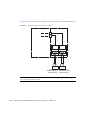
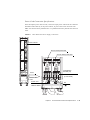


![DLP projectors [v03]](http://vs1.manualzilla.com/store/data/006167278_1-5898e6adff8e3a6708ad6510a0d56014-150x150.png)