1
SPARC Enterprise
M8000/M9000 Servers
Service Manual
Part No.: E27467-02
Manual Code: C120-E330-12EN
October 2012
Copyright © 2007, 2012, FUJITSU LIMITED. All rights reserved.
Oracle and/or its affiliates provided technical input and review on portions of this material.
Oracle and/or its affiliates and Fujitsu Limited each own or control intellectual property rights relating to products and technology described in this document, and such
products, technology and this document are protected by copyright laws, patents, and other intellectual property laws and international treaties.
This document and the product and technology to which it pertains are distributed under licenses restricting their use, copying, distribution, and decompilation. No part of
such product or technology, or of this document, may be reproduced in any form by any means without prior written authorization of Oracle and/or its affiliates and Fujitsu
Limited, and their applicable licensors, if any. The furnishings of this document to you does not give you any rights or licenses, express or implied, with respect to the
product or technology to which it pertains, and this document does not contain or represent any commitment of any kind on the part of Oracle or Fujitsu Limited, or any
affiliate of either of them.
This document and the product and technology described in this document may incorporate third-party intellectual property copyrighted by and/or licensed from the
suppliers to Oracle and/or its affiliates and Fujitsu Limited, including software and font technology.
Per the terms of the GPL or LGPL, a copy of the source code governed by the GPL or LGPL, as applicable, is available upon request by the End User. Please contact
Oracle and/or its affiliates or Fujitsu Limited.
This distribution may include materials developed by third parties.
Parts of the product may be derived from Berkeley BSD systems, licensed from the University of California. UNIX is a registered trademark in the U.S. and in other
countries, exclusively licensed through X/Open Company, Ltd.
Oracle and Java are registered trademarks of Oracle and/or its affiliates. Fujitsu and the Fujitsu logo are registered trademarks of Fujitsu Limited.
All SPARC trademarks are used under license and are registered trademarks of SPARC International, Inc. in the U.S. and other countries. Products bearing SPARC
trademarks are based upon architectures developed by Oracle and/or its affiliates. SPARC64 is a trademark of SPARC International, Inc., used under license by Fujitsu
Microelectronics, Inc. and Fujitsu Limited. Other names may be trademarks of their respective owners.
United States Government Rights - Commercial use. U.S. Government users are subject to the standard government user license agreements of Oracle and/or its affiliates
and Fujitsu Limited and the applicable provisions of the FAR and its supplements.
Disclaimer: The only warranties granted by Oracle and Fujitsu Limited, and/or any affiliate of either of them in connection with this document or any product or
technology described herein are those expressly set forth in the license agreement pursuant to which the product or technology is provided. EXCEPT AS EXPRESSLY
SET FORTH IN SUCH AGREEMENT, ORACLE OR FUJITSU LIMITED, AND/OR THEIR AFFILIATES MAKE NO REPRESENTATIONS OR WARRANTIES OF
ANY KIND (EXPRESS OR IMPLIED) REGARDING SUCH PRODUCT OR TECHNOLOGY OR THIS DOCUMENT, WHICH ARE ALL PROVIDED AS IS, AND
ALL EXPRESS OR IMPLIED CONDITIONS, REPRESENTATIONS AND WARRANTIES, INCLUDING WITHOUT LIMITATION ANY IMPLIED WARRANTY
OF MERCHANTABILITY, FITNESS FOR A PARTICULAR PURPOSE OR NON-INFRINGEMENT, ARE DISCLAIMED, EXCEPT TO THE EXTENT THAT
SUCH DISCLAIMERS ARE HELD TO BE LEGALLY INVALID. Unless otherwise expressly set forth in such agreement, to the extent allowed by applicable law, in no
event shall Oracle or Fujitsu Limited, and/or any of their affiliates have any liability to any third party under any legal theory for any loss of revenues or profits, loss of use
or data, or business interruptions, or for any indirect, special, incidental or consequential damages, even if advised of the possibility of such damages.
DOCUMENTATION IS PROVIDED “AS IS” AND ALL EXPRESS OR IMPLIED CONDITIONS, REPRESENTATIONS AND WARRANTIES, INCLUDING ANY
IMPLIED WARRANTY OF MERCHANTABILITY, FITNESS FOR A PARTICULAR PURPOSE OR NON-INFRINGEMENT, ARE DISCLAIMED, EXCEPT TO
THE EXTENT THAT SUCH DISCLAIMERS ARE HELD TO BE LEGALLY INVALID.
Please
Recycle
Copyright © 2007, 2012, FUJITSU LIMITED. Tous droits réservés.
Oracle et/ou ses sociétés affiliées ont fourni et vérifié des données techniques de certaines parties de ce composant.
Oracle et/ou ses sociétés affiliées et Fujitsu Limited détiennent et contrôlent chacune des droits de propriété intellectuelle relatifs aux produits et technologies décrits dans
ce document. De même, ces produits, technologies et ce document sont protégés par des lois sur le copyright, des brevets, d’autres lois sur la propriété intellectuelle et des
traités internationaux.
Ce document, le produit et les technologies afférents sont exclusivement distribués avec des licences qui en restreignent l’utilisation, la copie, la distribution et la
décompilation. Aucune partie de ce produit, de ces technologies ou de ce document ne peut être reproduite sous quelque forme que ce soit, par quelque moyen que ce soit,
sans l’autorisation écrite préalable d’Oracle et/ou ses sociétés affiliées et de Fujitsu Limited, et de leurs éventuels bailleurs de licence. Ce document, bien qu’il vous ait été
fourni, ne vous confère aucun droit et aucune licence, expresses ou tacites, concernant le produit ou la technologie auxquels il se rapporte. Par ailleurs, il ne contient ni ne
représente aucun engagement, de quelque type que ce soit, de la part d’Oracle ou de Fujitsu Limited, ou des sociétés affiliées de l’une ou l’autre entité.
Ce document, ainsi que les produits et technologies qu’il décrit, peuvent inclure des droits de propriété intellectuelle de parties tierces protégés par copyright et/ou cédés
sous licence par des fournisseurs à Oracle et/ou ses sociétés affiliées et Fujitsu Limited, y compris des logiciels et des technologies relatives aux polices de caractères.
Conformément aux conditions de la licence GPL ou LGPL, une copie du code source régi par la licence GPL ou LGPL, selon le cas, est disponible sur demande par
l’Utilisateur final. Veuillez contacter Oracle et/ou ses sociétés affiliées ou Fujitsu Limited.
Cette distribution peut comprendre des composants développés par des parties tierces.
Des parties de ce produit peuvent être dérivées des systèmes Berkeley BSD, distribués sous licence par l’Université de Californie. UNIX est une marque déposée aux
États-Unis et dans d’autres pays, distribuée exclusivement sous licence par X/Open Company, Ltd.
Oracle et Java sont des marques déposées d’Oracle Corporation et/ou de ses sociétés affiliées. Fujitsu et le logo Fujitsu sont des marques déposées de Fujitsu Limited.
Toutes les marques SPARC sont utilisées sous licence et sont des marques déposées de SPARC International, Inc., aux États-Unis et dans d’autres pays. Les produits
portant la marque SPARC reposent sur des architectures développées par Oracle et/ou ses sociétés affiliées. SPARC64 est une marque de SPARC International, Inc.,
utilisée sous licence par Fujitsu Microelectronics, Inc. et Fujitsu Limited. Tout autre nom mentionné peut correspondre à des marques appartenant à d’autres propriétaires.
United States Government Rights - Commercial use. U.S. Government users are subject to the standard government user license agreements of Oracle and/or its affiliates
and Fujitsu Limited and the applicable provisions of the FAR and its supplements.
Avis de non-responsabilité : les seules garanties octroyées par Oracle et Fujitsu Limited et/ou toute société affiliée de l’une ou l’autre entité en rapport avec ce document
ou tout produit ou toute technologie décrits dans les présentes correspondent aux garanties expressément stipulées dans le contrat de licence régissant le produit ou la
technologie fournis. SAUF MENTION CONTRAIRE EXPRESSÉMENT STIPULÉE DANS CE CONTRAT, ORACLE OU FUJITSU LIMITED ET LES SOCIÉTÉS
AFFILIÉES À L’UNE OU L’AUTRE ENTITÉ REJETTENT TOUTE REPRÉSENTATION OU TOUTE GARANTIE, QUELLE QU’EN SOIT LA NATURE
(EXPRESSE OU IMPLICITE) CONCERNANT CE PRODUIT, CETTE TECHNOLOGIE OU CE DOCUMENT, LESQUELS SONT FOURNIS EN L’ÉTAT. EN
OUTRE, TOUTES LES CONDITIONS, REPRÉSENTATIONS ET GARANTIES EXPRESSES OU TACITES, Y COMPRIS NOTAMMENT TOUTE GARANTIE
IMPLICITE RELATIVE À LA QUALITÉ MARCHANDE, À L’APTITUDE À UNE UTILISATION PARTICULIÈRE OU À L’ABSENCE DE CONTREFAÇON,
SONT EXCLUES, DANS LA MESURE AUTORISÉE PAR LA LOI APPLICABLE. Sauf mention contraire expressément stipulée dans ce contrat, dans la mesure
autorisée par la loi applicable, en aucun cas Oracle ou Fujitsu Limited et/ou l’une ou l’autre de leurs sociétés affiliées ne sauraient être tenues responsables envers une
quelconque partie tierce, sous quelque théorie juridique que ce soit, de tout manque à gagner ou de perte de profit, de problèmes d’utilisation ou de perte de données, ou
d’interruptions d’activités, ou de tout dommage indirect, spécial, secondaire ou consécutif, même si ces entités ont été préalablement informées d’une telle éventualité.
LA DOCUMENTATION EST FOURNIE « EN L’ÉTAT » ET TOUTE AUTRE CONDITION, DÉCLARATION ET GARANTIE, EXPRESSE OU TACITE, EST
FORMELLEMENT EXCLUE, DANS LA MESURE AUTORISÉE PAR LA LOI EN VIGUEUR, Y COMPRIS NOTAMMENT TOUTE GARANTIE IMPLICITE
RELATIVE À LA QUALITÉ MARCHANDE, À L’APTITUDE À UNE UTILISATION PARTICULIÈRE OU À L’ABSENCE DE CONTREFAÇON.
Contents
Preface
1.
xvii
Safety and Tools
1–1
1.1
Conventions for Alert Messages
1.2
Notes on Safety
1–2
1.2.1
Important Alert Messages
1.2.2
Alert Labels
Tools Required for Maintenance
1.4
Antistatic Precautions
2.
1–9
2.2
1–9
Removing Static Electricity on a CMU and an IOU
Grounding Port Connection Locations
System Overview and Troubleshooting
2.1
1–8
Removing Static Electricity
1.4.1.1
1.4.2
1–2
1–3
1.3
1.4.1
1–1
System Views
1–10
1–13
2–1
2–1
2.1.1
M8000 Server
2–3
2.1.2
M9000 Server (Base Cabinet)
2.1.3
M9000 Server (Expansion Cabinet)
Labels
2–11
2.2.1
System Name Plate Label, Rating Label, ID Label (Japan) or EZ Label
(besides Japan), and Standard Label 2–11
2–6
2–9
v
2.2.2
2.3
Labels About Handling
Operator Panel
2–17
2.3.1
Operator Panel Location
2.3.2
Appearance and Operations
2.3.3
LED
2.3.4
Switch
2–17
2–18
2–18
2–20
2.4
Determining Which Diagnostics Methods To Use
2.5
Checking the Server and System Configuration
2.5.1
2.5.2
2.5.3
2.6
2.7
2.8
2–21
2–23
Checking the Hardware Configuration and FRU Status
2.5.1.1
vi
2–15
Checking the Hardware Configuration
2–23
2–24
Checking the Software and XSCF Firmware Configurations
2.5.2.1
Checking the Software Configuration
2–25
2.5.2.2
Checking the Firmware Configuration
2–26
Downloading the Error Log Information
Error Conditions
2–26
2.6.1
Predictive Self-Healing Tools
2.6.2
Monitoring Output
2–28
2.6.3
Messaging Output
2–30
LED Error Display
2–26
2–27
2–30
2.7.1
When target FRU is indicated by LEDs
2.7.2
When target FRU is not indicated by LEDs
Using the Troubleshooting Commands
2–31
2–31
2–34
2.8.1
Using the showlogs Command
2.8.2
Using the fmdump Command
2.8.3
Using the fmadm Command
2–34
2–34
2–35
2.8.3.1
fmadm config Command
2–35
2.8.3.2
fmadm faulty Command
2–35
2.8.3.3
fmadm repair Command
2–36
SPARC Enterprise M8000/M9000 Servers Service Manual • October 2012
2–24
2.8.4
2.9
Using the fmstat Command
Traditional Oracle Solaris Troubleshooting Commands
2.9.1
2.9.2
iostat Command
2–37
2.9.1.1
2–38
Options
prtdiag Command
2.9.2.1
2.9.3
2.9.4
2.9.5
4.
2–41
netstat Command
2–45
Options
ping Command
2–45
2–46
Options
ps Command
2.9.6.1
2.9.7
2–41
Options
2.9.5.1
2.9.6
2–39
prtconf Command
2.9.4.1
2–46
2–47
Options
2–47
prstat Command
2–48
2.9.7.1
2–49
Periodic Maintenance
Options
3–1
3.1
Cleaning a Tape Drive Unit
3.2
Cleaning an Air Filter (Server)
3.3
Cleaning an Air Filter (I/O Unit)
FRU Replacement Preparation
3–1
3–2
Types of Replacement Procedures
4.2
Active Replacement
4.2.2
3–5
4–1
4.1
4.2.1
2–37
2–39
Options
2.9.3.1
3.
2–36
4–2
4–3
Disconnecting a FRU from a Domain
4–4
4.2.1.1
Disconnecting a CMU/IOU
4–4
4.2.1.2
Disconnecting a PCI card
4–4
Disconnecting and Replacing a FRU
4–6
Contents
vii
4.2.3
4.2.4
4.3
4.4
4.5
Configuring CMU/IOU
4–8
4.2.3.2
Configuring a PCI card
4–9
Confirming the Hardware
4–9
4–14
4.3.1
Disconnecting and Replacing a FRU
4.3.2
Confirming the Hardware
Cold Replacement
4–14
4–17
4–20
4.4.1
Powering the Server Off
4–21
4.4.2
Powering the Server On
4–22
4.4.3
Confirming the Hardware
4–23
Power-On/Off of Main Line Switch
Types of Power Supply
4–27
4–27
4.5.1.1
AC Input Power
4.5.1.2
Power System
4–27
4–29
4.5.2
Power-On/Off Procedures of Main Line Switch
4.5.3
Main Line Switch Locations
4.6
Emergency Switch-Off
4.7
Cable Routing of the M8000 Server
4.7.1
viii
4–8
4.2.3.1
Hot Replacement
4.5.1
5.
Configuring a FRU into a Domain
4–29
4–30
4–37
4–37
Cable Routing When the External I/O Expansion Unit Mounted
4–37
4.7.1.1
When Three External I/O Expansion Units Mounted
4–40
4.7.1.2
When One External I/O Expansion Unit Mounted
Internal Components Access
5–1
5.1
How to Open and Close Doors
5–1
5.2
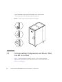
Corresponding Components and Doors That Can Be Accessed
5.3
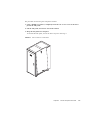
How to Remove a Door
5.4
How to Remove a Side Panel
5–3
5–4
SPARC Enterprise M8000/M9000 Servers Service Manual • October 2012
5–2
4–48
6.
Replacement of CPU/Memory Board Unit (CMU), CPU Module, and DIMM
6.1
Overview of the CMU
6.2
Active Replacement and Hot Replacement
6.3
Cold Replacement
6.4
CPU Module and DIMM Replacement
6.4.1
7.
8.
9.
10.
6–1
6–5
6–16
6–22
Notes on CPU Module Replacement
6–23
6.4.1.1
CPU Module Insertion/Extraction Tool
6.4.1.2
Handling the CPU Module
6.4.2
CPU Module Replacement
6.4.3
Notes on DIMM Replacement
6.4.4
6–25
6–34
Confirmation of DIMM Information
6.4.3.2
DIMM Mounting Conditions
DIMM Replacement
I/O Unit (IOU) Replacement
6–23
6–24
6.4.3.1
6–34
6–35
6–37
7–1
7.1
Overview of the IOU
7.2
Active Replacement and Hot Replacement
7.3
Cold Replacement
FAN Unit Replacement
6–1
7–2
7–8
7–19
8–1
8.1
Overview of the FAN Unit
8–2
8.2
Active Replacement and Hot Replacement
8.3
Cold Replacement
8–8
8–14
Power Supply Unit (PSU) Replacement
9–1
9.1
Overview of the PSU
9–1
9.2
Active Replacement and Hot Replacement
9.3
Cold Replacement
9–9
9–13
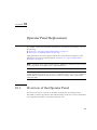
Operator Panel Replacement
10–1
Contents
ix
11.
12.
13.
14.
15.
x
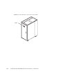
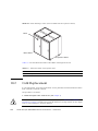
10.1
Overview of the Operator Panel
10.2
Cold Replacement
10–4
XSCF Unit Replacement
11–1
10–1
11.1
Overview of the XSCFU
11–1
11.2
Active Replacement and Hot Replacement
11.3
Cold Replacement
11–5
11–12
Hard Disk Drive (HDD) Replacement
12.1
Overview of the HDD
12.2
Active Replacement
12.3
Cold Replacement
12–1
12–1
12–4
12–8
PCI Slot Device Replacement
13–1
13.1
Overview of PCI Slot Devices
13–1
13.2
Active Replacement
13.3
Hot Replacement
13.4
Cold Replacement
13.5
Reactivating a Hardware RAID Boot Volume
13–4
13–18
13–21
CD-RW/DVD-RW Drive Unit Replacement
14–1
14.1
Overview of a CD-RW/DVD-RW Drive Unit
14.2
Active Replacement
14.3
Hot Replacement
14.4
Cold Replacement
14–6
14–10
14–12
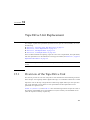
Tape Drive Unit Replacement
15–1
15.1
Overview of the Tape Drive Unit
15.2
Active Replacement
15.3
Hot Replacement
15.4
Cold Replacement
13–25
15–1
15–5
15–9
15–11
SPARC Enterprise M8000/M9000 Servers Service Manual • October 2012
14–1
16.
17.
18.
19.
20.
21.
22.
Clock Control Unit Replacement
16.1
Overview of the CLKU
16.2
Cold Replacement
16–1
16–4
Crossbar Unit Replacement
17–1
17.1
Overview of XBUs
17.2
Cold Replacement
17–4
AC Section Replacement
18–1
18.1
Overview of ACSs
18–1
18.2
Cold Replacement
18–5
DDC Replacement
16–1
17–1
19–1
19.1
Overview of the DDC
19.2
Active Replacement and Hot Replacement
19.3
Cold Replacement
19–7
Backplane Replacement
20–1
20.1
Overview of the BP
20.2
Cold Replacement
19–1
19–2
20–1
20–1
20.2.1
M8000/M9000 Server BPs
20.2.2
PSU BP
20–15
20.2.3
FAN BP
20–23
Sensor Unit Replacement
20–2
21–1
21.1
Overview of the SNSU
21.2
Cold Replacement
21–1
21–4
Media Backplane Replacement
22–1
22.1
Overview of the MEDBP
22–1
22.2
Cold Replacement
22–5
Contents
xi
23.
24.
Switch Backplane Replacement
23.1
Overview of SWBPs
23.2
Cold Replacement
23–5
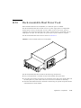
Addition and Deletion of Rack-mountable Dual Power Feed
24.1.1
Overview of RDPF
24.1.2
Addition and Deletion
24–3
24.1.2.1
Addition
24–3
24.1.2.2
Deletion
24–13
Addition and Deletion of Power Cabinet
24.3
Addition and Deletion of M9000 Expansion Cabinet
Addition, Deletion, and Upgrade of FRU
25.2
25.3
Addition
Active Addition
25.1.2
Cold Addition
24–16
25–1
25–2
25–2
25–4
25.2.1
Active Deletion
25.2.2
Cold Deletion
25–5
25–5
Upgrade of CPU, CMU, IOU, and IOUA
25.3.1
24–13
25–1
25.1.1
Deletion
24–1
24–2
24.2
25.1
xii
23–1
Addition and Deletion of a RDPF Option, Power Cabinet, and M9000 Expansion
Cabinet 24–1
24.1
25.
23–1
Notes on Upgrade
25–7
25–7
25.3.1.1
Supported Firmware and Software
25–7
25.3.1.2
Upgrade by Using DR
25.3.1.3
FRUs with Processors of Multiple Versions
25–8
25–8
25.3.2
CPU/CMU/IOU Add-on as an Upgrade in a New Domain
25–8
25.3.3
CPU Replacement as an Upgrade in an Existing Domain
25–10
25.3.4
CMU/IOU Replacement as an Upgrade in an Existing Domain
SPARC Enterprise M8000/M9000 Servers Service Manual • October 2012
25–13
25.3.5
CPU Add-on to an Existing CMU as an Upgrade in an Existing Domain
25–16
25.3.6
CMU/IOU Add-on as an Upgrade in an Existing Domain
25.3.7
Upgrade of IOUA
A. System Configuration
25–21
A–1
A.1
Installation Conditions
A.2
System Configuration
A–1
A–2
A.2.1
M8000 Server
A.2.2
M9000 Server (Base Cabinet)
A.2.3
M9000 Server (Base Cabinet + Expansion Cabinet)
B. Components
25–18
A–2
A–4
A–7
B–1
B.1
CPU/Memory Board Unit
B–4
B.2
CPU Module
B.3
Memory
B–8
B.4
I/O Unit
B–9
B.5
Hard Disk Drive
B.6
PCI Cassette
B.7
IOU Onboard Device Card
B.8
Link Card (External I/O Expansion Unit Connection Card)
B.9
Crossbar Unit
B.10
Clock Control Unit
B.11
XSCF Unit
B.12
CD-RW/DVD-RW Drive Unit
B.13
Tape Drive Unit
B.14
Operator Panel
B.15
Sensor Unit
B.16
Power Supply Unit
B.17
AC Section
B–6
B–11
B–12
B–13
B–14
B–15
B–17
B–17
B–20
B–21
B–24
B–26
B–27
B–28
Contents
xiii
B.18
FAN Unit
B–33
B.19
Power Cabinet
B.20
Rack-mountable Dual Power Feed
B.21
Backplane
B.22
DDC
B.23
PSU Backplane
B–41
B.24
FAN Backplane
B–42
B.25
Media Backplane
B–45
B.26
Switch Backplane
B–46
B–35
B–37
B–38
B–40
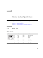
C. External Interface Specifications
C–1
C.1
Serial Port
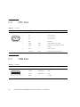
C.2
UPC Port
C–2
C.3
USB Port
C–2
C.4
Connection Diagram for Serial Cable
D. UPS Controller
C–1
C–3
D–1
D.1
Overview
D–1
D.2
Signal Cable
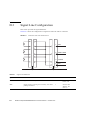
D.3
Signal Line Configuration
D–2
D.4
Power Supply Conditions
D–4
D–1
D.4.1
Input Circuit
D.4.2
Output Circuit
D.5
UPS Cable
D.6
Connections
D.7
UPC Port
D–4
D–4
D–5
D–6
D–7
E. XSCF Unit Replacement When XCP 1040 or 1041 Is in the Server
Abbreviations
xiv
Abbreviations–1
SPARC Enterprise M8000/M9000 Servers Service Manual • October 2012
E–1
Index
Index–1
Contents
xv
xvi
SPARC Enterprise M8000/M9000 Servers Service Manual • October 2012
Preface
This manual is a maintenance manual for the SPARC Enterprise M8000/M9000 servers from
Oracle and Fujitsu. The manual explains basic operations and detailed replacement
procedures for field-replaceable units (FRUs), which are components that can be replaced at
the customer's site. References herein to the M8000 server or M9000 server are references to
the SPARC Enterprise M8000 or SPARC Enterprise M9000 server.
This chapter includes the following sections:
■
“Audience” on page xvii
■
“Related Documentation” on page xviii
■
“Text Conventions” on page xix
■
“Notes on Safety” on page xix
■
“Syntax of the Command-Line Interface (CLI)” on page xx
■
“Documentation Feedback” on page xx
Audience
This guide is written for experienced system administrators with working knowledge of
computer networks and advanced knowledge of the Oracle Solaris Operating System (Oracle
Solaris OS).
xvii
Related Documentation
All documents for your server are available online at the following locations:
Documentation
Link
Sun Oracle software-related manuals
(Oracle Solaris OS, and so on)
http://www.oracle.com/documentation
Fujitsu documents
http://www.fujitsu.com/sparcenterprise/manual/
Oracle M-series server documents
http://www.oracle.com/technetwork/documentation/spa
rc-mseries-servers-252709.html
The following table lists titles of related documents.
Related SPARC Enterprise M8000/M9000 Servers Documents
SPARC Enterprise M8000/M9000 Servers Site Planning Guide
SPARC Enterprise M8000/M9000 Servers Getting Started Guide*
SPARC Enterprise M8000/M9000 Servers Overview Guide
SPARC Enterprise M3000/M4000/M5000/M8000/M9000 Servers Important Legal and Safety Information *
SPARC Enterprise M8000/M9000 Servers Safety and Compliance Guide
External I/O Expansion Unit Safety and Compliance Guide
SPARC Enterprise M8000/M9000 Servers Unpacking Guide*
SPARC Enterprise M8000/M9000 Servers Installation Guide
SPARC Enterprise M8000/M9000 Servers Service Manual
External I/O Expansion Unit Installation and Service Manual
SPARC Enterprise M3000/M4000/M5000/M8000/M9000 Servers Administration Guide
SPARC Enterprise M3000/M4000/M5000/M8000/M9000 Servers XSCF User’s Guide
SPARC Enterprise M3000/M4000/M5000/M8000/M9000 Servers XSCF Reference Manual
Dynamic Reconfiguration (DR) User’s Guide
SPARC Enterprise M4000/M5000/M8000/M9000 Servers Capacity on Demand (COD) User’s Guide
SPARC Enterprise M3000/M4000/M5000/M8000/M9000 Servers Product Notes†
SPARC Enterprise M8000/M9000 Servers Product Notes
External I/O Expansion Unit Product Notes
SPARC Enterprise M3000/M4000/M5000/M8000/M9000 Servers Glossary
xviii
SPARC Enterprise M8000/M9000 Servers Service Manual • October 2012
* This is a printed document.
† Beginning with the XCP 1100 release.
Text Conventions
This manual uses the following fonts and symbols to express specific types of information.
Font/Symbol
Meaning
Example
AaBbCc123
What you type, when contrasted with
on-screen computer output.
This font represents the example of
command input in the frame.
XSCF> adduser jsmith
AaBbCc123
The names of commands, files, and
directories; on-screen computer
output.
This font represents the example of
command output in the frame.
XSCF> showuser -P
User Name:
jsmith
Privileges: useradm
auditadm
Italic
Indicates the name of a reference
manual, a variable, or user-replaceable
text.
See the SPARC Enterprise
M3000/M4000/M5000/M8000/M9000
Servers XSCF User’s Guide.
""
Indicates names of chapters, sections,
items, buttons, or menus.
See Chapter 2, "System Features."
Notes on Safety
Read the following documents thoroughly before using or handling any SPARC Enterprise
M8000/M9000 server.
■
SPARC Enterprise M3000/M4000/M5000/M8000/M9000 Servers Important Legal and
Safety Information
■
SPARC Enterprise M8000/M9000 Servers Safety and Compliance Guide
Preface
xix
Syntax of the Command-Line Interface
(CLI)
The command syntax is as follows:
■
A variable that requires input of a value must be put in Italics.
■
An optional element must be enclosed in [].
■
A group of options for an optional keyword must be enclosed in [] and delimited by |.
Documentation Feedback
If you have any comments or requests regarding this document, go to the following websites:
■
For Oracle users:
http://www.oracle.com/goto/docfeedback
Include the title and part number of your document with your feedback:
SPARC Enterprise M8000/M9000 Servers Service Manua, part number E27467-01
■
For Fujitsu users in other countries, refer to this SPARC Enterprise contact:
http://www.fujitsu.com/global/contact/computing/sparce_index.html
xx
SPARC Enterprise M8000/M9000 Servers Service Manual • October 2012
PA RT
I
Basic Information for Maintenance and
Troubleshooting
Part I provides basic information for maintenance, and explains troubleshooting, periodic
maintenance, and the basic operations for replacing FRUs.
C H A PT E R
1
Safety and Tools
This chapter provides notes on handling the SPARC Enterprise M8000/M9000 servers, and
describes the required tools for maintenance.
This information is explained in the following sections:
■
■
■
■
1.1
Section 1.1,
Section 1.2,
Section 1.3,
Section 1.4,
“Conventions for Alert Messages” on page 1-1
“Notes on Safety” on page 1-2
“Tools Required for Maintenance” on page 1-8
“Antistatic Precautions” on page 1-9
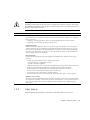
Conventions for Alert Messages
This manual uses the following conventions to show alert messages, which are intended to
prevent injury to the user or bystanders as well as property damage, and important messages
that are useful to the user.
Caution – The WARNING signal indicates a hazardous situation that could result in death
or serious personal injury (potential hazard) if the user does not perform the procedure
correctly.
Caution – The CAUTION signal indicates a hazardous situation that could result in minor
or moderate personal injury if the user does not perform the procedure correctly. This signal
also indicates that damage to the product or other property may occur if the user does not
perform the procedure correctly.
1-1
Note – This indicates information that could help the user to use the product more
effectively.
1.2
Notes on Safety
This section explains the important alert messages and the alert labels affixed on the servers.
1.2.1
■
Section 1.2.1, “Important Alert Messages” on page 1-2
■
Section 1.2.2, “Alert Labels” on page 1-3
Important Alert Messages
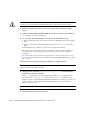
Before performing the maintenance work, confirm the following notes on safety:
Caution – The WARNING signal indicates a dangerous situation could result in death or
serious injury if the user does not perform the procedure correctly.
Task
Warning
Normal operation
Electric shock, fire
Do not damage, break, or modify the power cords. Cord damage may cause electric shock or fire.
Maintenance
Electric shock, injury, fire
Only authorized service engineers should perform the work listed below. Otherwise, electric shock,
injury, or fire may result.
• Installation, transport, and initial setup of each device
• Removal of the front, rear, or a side cover.
• Mounting or removing internal optional components
• Connecting or disconnecting an external interface cable
• Maintenance (repair, regular diagnosis, and maintenance)
Electric shock
When you perform active maintenance, do not pull out two or more active maintenance units. Doing
so may cause electric shock.
Modification
1-2
Electric shock, injury or fire
Do not make mechanical or electrical modifications to the equipment. The company is not
responsible for regulatory compliance of a modified product.
SPARC Enterprise M8000/M9000 Servers Service Manual • October 2012
Caution – The CAUTION signal indicates a hazardous situation could result in minor or
moderate personal injury if the user does not perform the procedure correctly. This signal
also indicates that damage to the product or other property may occur if the user does not
perform the procedure correctly.
Task
Warning
Maintenance
Equipment failure
Only authorized service engineers should perform the work listed below. Otherwise, an equipment
failure may result.
• Unpacking or installing products, such as an optional adapter, delivered to the customer
• Connecting or disconnecting an external interface cable
Equipment damage
Before handling the components, be sure to connect the clip of the antistatic wrist strap and the
antistatic mat to the server grounding port, and attach the band of the wrist strap to one of your
wrists. Place the component on the grounded antistatic mat with your hand wearing the antistatic
wrist strap, to eliminate static electricity in advance of installation. Failure to take these antistatic
measures might result in serious damage.
Data destruction
Confirm the following items before performing the maintenance work. Otherwise, data may be
destroyed.
• Confirm the items listed below before turning off the power.
- All applications have completed processing.
- No user is using the equipment.
- When the main unit power is turned off, the POWER LED on the operation panel is turned off.
Be sure to confirm that the POWER LED is off before turning off the main power
(uninterruptible power supply [UPS], power distribution box, main line switch, etc.).
If necessary, back up files before turning off the system power.
• Do not forcibly stop a domain that is operating normally.
• Do not disconnect the power cord from the AC power input while power is being supplied.
Emission of Laser Beam
The server contains modules that generate invisible laser radiation. Laser beams are generated while
the equipment is operating, even if an optical cable is disconnected or a cover is removed. Do not
look at any laser light source directly or through an optical apparatus (e.g., magnifying glass,
microscope).
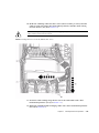
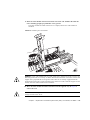
1.2.2
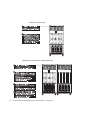
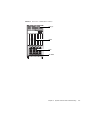
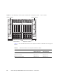
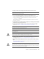
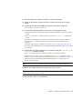
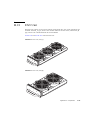
Alert Labels
When performing the maintenance, observe the alert labels affixed on the server.
Chapter 1
Safety and Tools
1-3
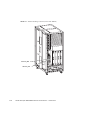
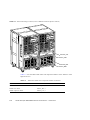
Caution – Do not peel off the labels.
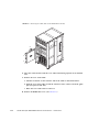
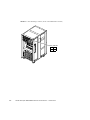
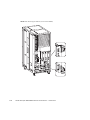
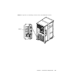
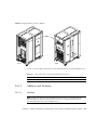
M8000 Server (Front View)
1-4
SPARC Enterprise M8000/M9000 Servers Service Manual • October 2012
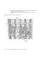
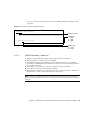
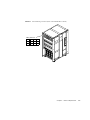
M9000 Server (Front View)
Chapter 1
Safety and Tools
1-5
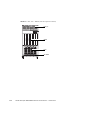
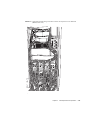
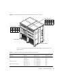
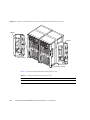
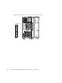
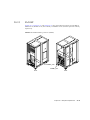
M9000 Server (Rear View)
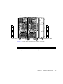
M9000 Server with Expansion Cabinet (Rear View)
1-6
SPARC Enterprise M8000/M9000 Servers Service Manual • October 2012
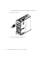
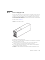
Power Supply Unit (PSU)
Chapter 1
Safety and Tools
1-7
1.3
Tools Required for Maintenance
The maintenance work described in Chapter 6 to Chapter 24 requires maintenance software
to confirm that the server and other components are operating correctly and to collect status
information and log data about the server and components. The work for mounting,
removing, or replacing a specific component requires screwdrivers, and special tools such as
an antistatic wrist strap. These items are listed in TABLE 1-1.
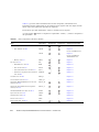
TABLE 1-1
Maintenance Tools
No.
Name
Use
1
Torque wrench
[8.24 N•m (84 kgf•cm)]
Used to secure the bus bars of the power cabinet.
2
Sockets for 10 mm (M6) torque
wrench
Used to replace the backplane (BP_A) in the M8000 server.
3
Sockets for 13 mm (M8) torque
wrench
Used to secure the bus bars of the power cabinet.
4
Torque wrench extension
5
Torque screwdriver
[0.2 N•m (2.0 kgf•cm)]
Used to secure the clock cables between the cabinets if the expansion
cabinet of the M9000 server is installed.
6
Slotted bit
Used to secure the clock cables between the cabinets if the expansion
cabinet of the M9000 server is installed.
7
Wrist strap
For antistatic purposes
8
Antistatic mat
For antistatic purposes
9
CPU module replacement tool
For mounting and removing CPU Modules (accessory)
10
Oracle VTS
Test program
Caution – Before handling the components, be sure to connect the clip of the antistatic
wrist strap and the antistatic mat to the server grounding port, and attach the band of the
wrist strap to one of your wrists. Place the component on the grounded antistatic mat with
your hand wearing the antistatic wrist strap, to eliminate static electricity in advance of
installation. Failure to take these antistatic measures might result in serious damage.
1-8
SPARC Enterprise M8000/M9000 Servers Service Manual • October 2012
1.4
Antistatic Precautions
During normal operations, all components mounted in the server, including the dummy
(filler) units, are properly grounded through the chassis.
Prior to performing maintenance, ensure that any static electricity is discharged from the
FRUs to be inserted and the person performing the maintenance. Both must be properly
grounded.
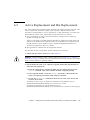
Ensure that the procedures below are followed for proper grounding.
1.4.1
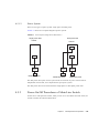
Removing Static Electricity
This section explains the procedures for removing static electricity.
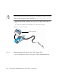
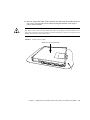
1. Connect the earth conductor of the antistatic mat to the server grounding port. (See
FIGURE 1-7 to FIGURE 1-10)
Note – Do not use antistatic bags or packaging materials in place of a grounded antistatic
mat when handling the FRUs.
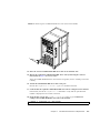
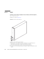
FIGURE 1-1
Antistatic Mat
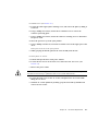
2. Connect an antistatic wrist strap clip to a server grounding port. (See FIGURE 1-7 to
FIGURE 1-10)
Chapter 1
Safety and Tools
1-9
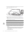
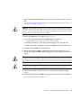
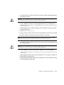
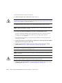
Caution – Before handling FRUs, be sure to connect the clip of the antistatic wrist strap
and of the antistatic mat to the server grounding port, and attach the band of the wrist strap
to one of your wrists. Place the FRUs on the grounded antistatic mat. Failure to take these
antistatic measures might result in serious damage.
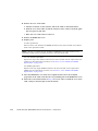
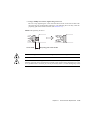
3. Ensure that the metallic underside of the wrist strap is in direct contact with your
skin.
The wrist strap should be snug around the wrist so that it does not rotate.
FIGURE 1-2
Antistatic Wrist Strap
metallic underside
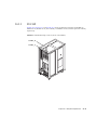
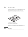
1.4.1.1
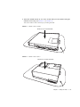
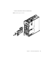
Removing Static Electricity on a CMU and an IOU
1. Prior to mounting a new CMU or IOU, place it on the grounded antistatic mat.
1-10
SPARC Enterprise M8000/M9000 Servers Service Manual • October 2012
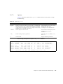
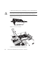
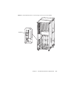
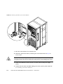
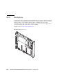
2. Touch the metallic chassis for 5 or more seconds with your bare hand wearing the
antistatic wrist strap. (See FIGURE 1-3 or FIGURE 1-4)
You cannot remove static electricity by touching the label.
FIGURE 1-3
Metallic Chassis (CMU)
Touch for 5 or more seconds.
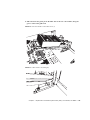
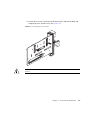
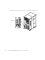
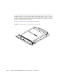
FIGURE 1-4
Metallic Chassis (IOU)
Touch for 5 or more seconds.
Chapter 1
Safety and Tools
1-11
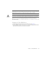
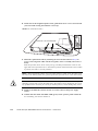
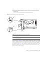
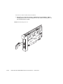
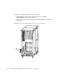
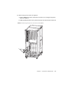
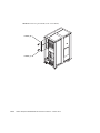
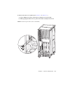
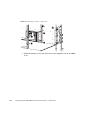
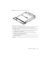
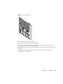
3. Touch each of the designated points on the guide blocks for 5 or more seconds with
your bare hand wearing the antistatic wrist strap. (See FIGURE 1-5 or FIGURE 1-6)
FIGURE 1-5
Guide Block (CMU)
Touch for 5 or more seconds.
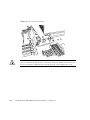
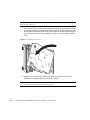
FIGURE 1-6
Guide Block (IOU)
Touch 5 or more seconds.
1-12
SPARC Enterprise M8000/M9000 Servers Service Manual • October 2012
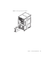
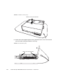
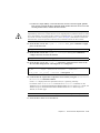
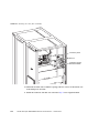
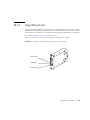
1.4.2
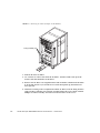
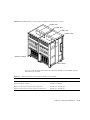
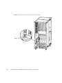
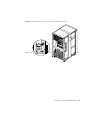
Grounding Port Connection Locations
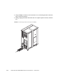
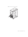
FIGURE 1-7 to FIGURE 1-10 show the locations of the grounding port on each server.
The grounding port can be used for the grounding of the antistatic wrist strap and the
antistatic mat.
If the type of clip does not securely fit the grounding port, it can also be connected to the
grounding wire for the door. For details, see Section 5.3, “How to Remove a Door” on
page 5-3.
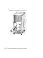
FIGURE 1-7
M8000 Grounding Port Connection Locations (Front View)
Chapter 1
Safety and Tools
1-13
1-14
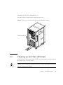
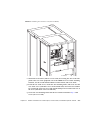
FIGURE 1-8
M8000 Grounding Port Connection Locations (Rear View)
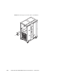
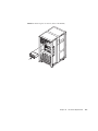
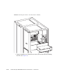
FIGURE 1-9
M9000 Grounding Port Connection Locations (Front View)
SPARC Enterprise M8000/M9000 Servers Service Manual • October 2012
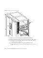
FIGURE 1-10
M9000 Grounding Port Connection Locations (Rear View)
Chapter 1
Safety and Tools
1-15
1-16
SPARC Enterprise M8000/M9000 Servers Service Manual • October 2012
C H A PT E R
2
System Overview and Troubleshooting
This chapter provides information that is required in troubleshooting.
This information is explained in the following sections:
■
■
■
■
■
■
■
■
■
2.1
Section 2.1,
Section 2.2,
Section 2.3,
Section 2.4,
Section 2.5,
Section 2.6,
Section 2.7,
Section 2.8,
Section 2.9,
“System Views” on page 2-1
“Labels” on page 2-11
“Operator Panel” on page 2-17
“Determining Which Diagnostics Methods To Use” on page 2-21
“Checking the Server and System Configuration” on page 2-23
“Error Conditions” on page 2-26
“LED Error Display” on page 2-30
“Using the Troubleshooting Commands” on page 2-34
“Traditional Oracle Solaris Troubleshooting Commands” on page 2-37
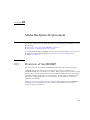
System Views
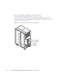
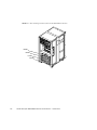
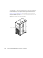
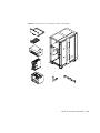
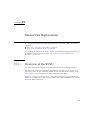
This section provides views of the high-end server. The figures can be used to locate the
component in the server to be subjected to maintenance.
In terms of its structure, the high-end server consists of a cabinet that includes various
mounted components and a front door, rear door, and side covers that protect the mounted
components. The side covers are removed when cabinets are connected to each other or when
the dual power feed option is connected to the cabinet. The operator panel, which is mounted
on the front door, is always accessible. Each door can be locked with a key so that only the
administrator can open it.
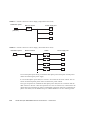
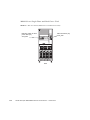
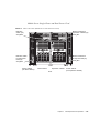
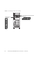
The front and rear views of FIGURE 2-1, FIGURE 2-2, FIGURE 2-4, FIGURE 2-5, FIGURE 2-7, and
FIGURE 2-8 include names and abbreviations for field-replaceable units (FRUs). Components
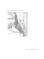
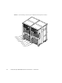
that are mounted inside the system are shown FIGURE 2-3, FIGURE 2-6, and FIGURE 2-9. The
abbreviations are used in messages and the like. If multiple FRUs of the same type are
mounted, the number sign # and a sequential number is added to their names to distinguish
2-1
them from one another. Owing to the reduced scale, certain components (FRUs) are difficult
to show in the figures. Accordingly, the layout of these components as viewed from one side
is indicated in the table connected by a lead line to the component location.
2-2
SPARC Enterprise M8000/M9000 Servers Service Manual • October 2012
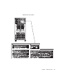
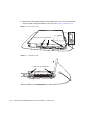
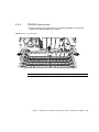
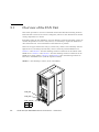
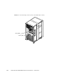
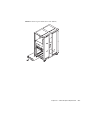
2.1.1
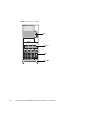
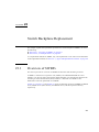
M8000 Server
FIGURE 2-1
Front View - M8000
PSU
DDC
XSCFU
CMU
TAPEU
DVDU
FAN_A
SNSU
FAN_B
Air Filter
Chapter 2
System Overview and Troubleshooting
2-3
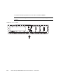
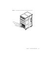
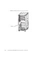
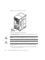
FIGURE 2-2
Rear View - M8000
ACS
FAN_B
IOU
Air Filter
2-4
SPARC Enterprise M8000/M9000 Servers Service Manual • October 2012
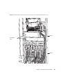
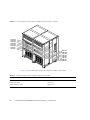
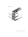
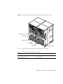
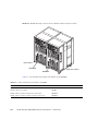
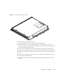
FIGURE 2-3
Internal View - M8000
PSUBP_B
PSUBP_A
FANBP_C
BP_A
MEDBP
SWBP
FANBP_C
Chapter 2
System Overview and Troubleshooting
2-5
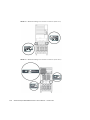
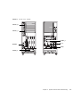
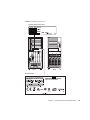
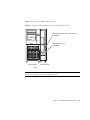
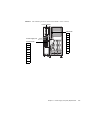
2.1.2
M9000 Server (Base Cabinet)
FIGURE 2-4
PSU
Front View - M9000 (Base Cabinet)
FAN_A
ACS
XBU
CLKU
XSCFU
IOU
TAPEU
DVDU
Air Filter
SNSU
2-6
SPARC Enterprise M8000/M9000 Servers Service Manual • October 2012
FIGURE 2-5
Rear View - M9000 (Base Cabinet)
FAN_A
CMU
IOU
Air Filter
Chapter 2
System Overview and Troubleshooting
2-7
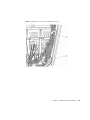
Internal View - M9000 (Base Cabinet)
FIGURE 2-6
PSUBP_A
FANBP_B
FANBP_A
BP_B
MEDBP
SWBP
2-8
SPARC Enterprise M8000/M9000 Servers Service Manual • October 2012
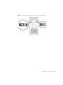
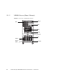
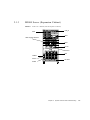
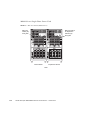
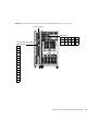
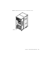
2.1.3
M9000 Server (Expansion Cabinet)
FIGURE 2-7
Front View - M9000 (with the Expansion Cabinet)
FAN_A
PSU
ACS
cable support bracket
XBU
CLKU
XSCFU
IOU
TAPEU
DVDU
Air Filter
SNSU
Chapter 2
System Overview and Troubleshooting
2-9
FIGURE 2-8
Rear View - M9000 (with the Expansion Cabinet)
FAN_A
CMU
IOU
Air Filter
2-10
SPARC Enterprise M8000/M9000 Servers Service Manual • October 2012
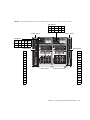
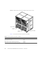
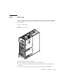
FIGURE 2-9
Internal View - M9000 (with the Expansion Cabinet)
FANBP_B
PSUBP_A
FANBP_A
BP_B
MEDBP
SWBP
2.2
Labels
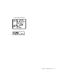
2.2.1
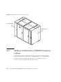
System Name Plate Label, Rating Label, ID Label
(Japan) or EZ Label (besides Japan), and Standard
Label
The important labels affixed on this server are shown in FIGURE 2-10 and FIGURE 2-11. The
actual description on the labels may differ from FIGURE 2-10 and FIGURE 2-11.
■
The system name plate label includes the model number, serial number, and hardware
version, all of which are required for maintenance and management.
■
The rating label, which is affixed near the AC power supply, includes the power input
rating for the AC power supply.
Chapter 2
System Overview and Troubleshooting
2-11
■
The ID label or EZ label is affixed on the front door of the server, and it includes the
model name and serial number, both of which are written on the system name plate label.
ID label (Japan)
■
EZ label (besides Japan)
The standard label is affixed near the system name plate label, and it includes the
certification standards that apply:
Safety: NRTL/C
Electrical interference: VCCI-A, FCC-A, DOC-A, and MIC
Safety and electrical interference: CE
2-12
SPARC Enterprise M8000/M9000 Servers Service Manual • October 2012
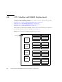
FIGURE 2-10
M8000 Label Location
System Name Plate Label
Front
Rear
Standard label
Chapter 2
System Overview and Troubleshooting
2-13
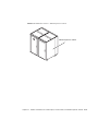
FIGURE 2-11
M9000 Label Location
System Name Plate Label
Front
Rear
Standard label
2-14
SPARC Enterprise M8000/M9000 Servers Service Manual • October 2012
2.2.2
Labels About Handling
The labels shown below, which are affixed on the server, provide field engineers with
important information on component removal and mounting.
Caution – Never peel off the labels.
■
Removing and installing a CPU/memory board unit (CMU)
■
Removing a crossbar unit (XBU)
Chapter 2
System Overview and Troubleshooting
2-15
■
2-16
Removing an I/O unit (IOU)
SPARC Enterprise M8000/M9000 Servers Service Manual • October 2012
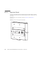
2.3
Operator Panel
The operator panel controls the high-end server power. The operator panel is usually locked
with a key to prevent the server from being mistakenly powered off through an operator error
during system operation.
Before starting maintenance work, ask the system administrator to unlock the operation
panel.
2.3.1
Operator Panel Location
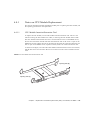
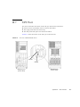
FIGURE 2-12 indicates the location of the operator panel (OPNL) of the high-end servers. The
operator panel is mounted on the front door of the M8000 server and the M9000 server (base
cabinet). The expansion cabinet is not equipped with the operator panel.
FIGURE 2-12
Operator Panel Location (at the Front of M8000)
OPNL
Chapter 2
System Overview and Troubleshooting
2-17
2.3.2
Appearance and Operations
The operator panel can be used while the front door of the server is closed. Field engineers,
and the system administrator use the operation panel to check the operating state of the
server and to perform system power operations. The operating state of the server is checked
by observing the LEDs, and the power supply is operated with the POWER switch.
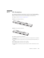
FIGURE 2-13 shows the appearance of the operator panel.
FIGURE 2-13
2.3.3
Operator Panel
LED
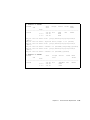
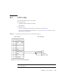
TABLE 2-1 lists the states of the server that are displayed with the LEDs on the operator panel.
The blinking period is one second (frequency of 1 Hz).
Besides the states listed in TABLE 2-1, the operator panel also displays various states of the
server using combinations of the three LEDs. TABLE 2-2 indicates the states that are usually
displayed in the course of operation from the power-on to power-off of the high-end server.
TABLE 2-1
LED
2-18
State Display by the LEDs (Operator Panel)
Name
Light Color
Description of Function and State
POWER
Green
Indicates whether power to the SPARC Enterprise server is on.
Off
Indicates the power-off state.
Lit
Indicates the power-on state.
Blinking
The power-off sequence is in progress.
SPARC Enterprise M8000/M9000 Servers Service Manual • October 2012
TABLE 2-1
LED
State Display by the LEDs (Operator Panel) (Continued)
Name
Light Color
Description of Function and State
STANDBY
Green
Indicates whether the XSCF can be powered on.
XSCF
CHECK
Amber
Off
Indicates that the system cannot be powered on.
Blinking
Indicates that initialization processing of the server is in
progress after main line switches were switched on.
Lit
Indicates that the system can be powered on.
Indicates the operating status of the server.
Off
Normal state. Otherwise, this indicates that the main line
switches were switched off or a power failure occurred.
Blinking*
Indicates that the operator panel is the maintenance target
device.
Lit
Indicates that the server cannot be started.
* If the maintenance target component is indicted by a blinking CHECK LED, the LED may be called a locator.
TABLE 2-2
State Display by LED Combination (Operator Panel)
LED
POWER
XSCF
STANDBY
CHECK
Description of the State
Off
Off
Off
The main line switch is switched off.
Off
Off
On
The main line switch is switched on.
Off
Blinking
Off
The XSCF is being initialized.
Off
Blinking
On
An error occurred in the XSCF.
Off
On
Off
• The XSCF is on standby.
• The system is waiting for power-on of the air conditioning system.
On
On
Off
• Warm-up standby processing is in progress (power-on is delayed).
• The power-on sequence is in progress.
• The system is in operation.
Blinking
On
Off
• The power-off sequence is in progress.
• Fan termination is being delayed.
Chapter 2
System Overview and Troubleshooting
2-19
2.3.4
Switch
The operator panel has the mode switch, which sets the operation mode, and the POWER
switch, which is used to power on and off the system.
TABLE 2-3
Switch
Switches (Operator Panel)
Name
Description of Function
Mode
This key switch is used to set an operation mode for the server.
Insert the special key that is under the customer’s control, to switch
between modes.
Locked
Normal operation mode
• The system can be powered on with the POWER switch, but it
cannot be powered off with the POWER switch.
• The key can be pulled out at this key position.
Service
Mode for maintenance
• The system can be powered on and off with the POWER switch.
• The key cannot be pulled out at this key position.
• Maintenance is performed in Service mode while the server is
stopped.
POWER
This switch is used to control the server power.
Power-on and power-off are controlled by pressing this switch in
different patterns, as described below.
Holding down for a
short time
(less than 4 seconds)
Regardless of the mode switch state, the server (all domains) is
powered on.
At this time, processing for waiting for facility (air conditioners)
power-on and warm-up completion is skipped.*
Holding down for a
long time in Service
mode
(4 seconds or longer)
• If power to the server is on (at least one domain is operating),
shutdown processing is executed for all domains before power-off
processing.
• If the system is being powered on, the power-on processing is
cancelled, and the system is powered off.
• If the system is being powered off, the operation of the POWER
switch is ignored, and the power-off processing is continued.
* In normal operation, the server is powered on only when the computer room environmental conditions satisfy the specified values. Then, the server
remains in the reset state until the operating system is booted.
2-20
SPARC Enterprise M8000/M9000 Servers Service Manual • October 2012
TABLE 2-4
Meanings of the Mode Switch
Function
Mode Switch
Locked
Locked
Inhibition of Break Signal Reception
Enabled. Reception of the break signal can
be enabled or disabled for each domain
using setdomainmode.
Disabled
Power On/Off by power switch
Only power on is enabled
Enabled
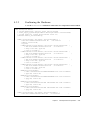
2.4
Determining Which Diagnostics Methods To
Use
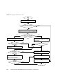
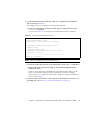
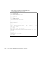
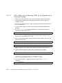
When an error occurs, a message is often displayed on the monitor. Use the flowcharts in
FIGURE 2-14 to find the correct methods for diagnosing problems.
Chapter 2
System Overview and Troubleshooting
2-21
FIGURE 2-14
Diagnostic Method Flow Chart
Start
OS panic occurred or there’s an
error on performance
YES
e-mail sent or not by
XSCF mail function?
NO
Check OS console and XSCF
console for error information displayed
NO
Is there error message
on XSCF console?
Execute showlogs or fmadm
on XSCF to display the fault
information
Check /var/adm/messages
on Oracle Solaris OS
FMA message?
YES
NO
YES
Use fmadm ?
YES
NO
Execute fmadm to display fault
information
NO
Message ID
available?
Write down the displayed fault
information
YES
Enter Message ID in
Collect information about your
server
http://sun.com/msg/ to
refer to fault information
Contact service engineer
NO
Trouble
resolved?
YES
2-22
SPARC Enterprise M8000/M9000 Servers Service Manual • October 2012
End
2.5
Checking the Server and System
Configuration
Before and after maintenance work, the state and configuration of the server and components
should be checked and the information saved. For recovery from a problem, conditions
related to the problem and the repair status must be checked. The operating conditions must
remain the same before and after maintenance.
A functioning server without any problems should not display any error conditions. For
example:
2.5.1
■
The syslog file should not display error messages.
■
* mark is not displayed in XSCF shell command showhardconf
■
The administrative console should not display error messages.
■
The server processor logs should not display any error messages.
■
The Oracle Solaris Operating System (Oracle Solaris OS) message files should not
indicate any additional errors.
Checking the Hardware Configuration and FRU Status
To replace a faulty component and perform the maintenance on the server, it is important to
check and understand the hardware configuration of the server and the state of each hardware
component.
The hardware configuration refers to information that indicates to what layer a component
belongs in the hardware configuration.
The status of each hardware component refers to information on the condition of the standard
or optional component in the server: temperature, power supply voltage, CPU operating
conditions, and other times.
The hardware configuration and the status of each hardware component can be checked from
the maintenance terminal using XSCF Shell commands.
Chapter 2
System Overview and Troubleshooting
2-23
TABLE 2-5 lists commands for checking the hardware configuration and status. For details,
see the SPARC Enterprise M3000/M4000/M5000/M8000/M9000 Servers XSCF Reference
Manual.
TABLE 2-5
Commands for Checking Hardware Configuration and FRU Status
Command
Description
showhardconf
Displays the system layer that includes a faulty component.
showstatus
Displays the status of a component. This command is used to check only a faulty component.
showboards
Displays the use status of individual devices and resources.
showdcl
Displays domain configuration information (hardware resource information).
showfru
Displays device setting information.
ioxadm
Displays the FRU status of external I/O expansion unit as normal or abnormal.
Also some conditions can be checked based on the lit and/or blinking state of the component
LEDs. See TABLE 2-11 and TABLE 2-12.
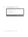
2.5.1.1
Checking the Hardware Configuration
Login authority is required to check the hardware configuration. The following procedure for
these checks can be made from the maintenance terminal. Ask the system administrator for
necessary information, such as a password. For the detailed procedure, see the SPARC
Enterprise M3000/M4000/M5000/M8000/M9000 Servers XSCF User’s Guide.
1. Log in to the XSCF.
2. Execute the showhardconf command.
XSCF> showhardconf
The showhardconf command will print the hardware configuration information to the
screen. For the detailed procedure, see the SPARC Enterprise
M3000/M4000/M5000/M8000/M9000 Servers XSCF User’s Guide.
2.5.2
Checking the Software and XSCF Firmware
Configurations
The software and firmware configurations and versions affect the operation of the server. To
change the configuration or investigate a problem, check the latest information and check for
any problems in the software.
2-24
SPARC Enterprise M8000/M9000 Servers Service Manual • October 2012
Software and firmware varies according to users.
■
The software configuration and version can be checked in the Oracle Solaris OS. Refer to
the Oracle Solaris OS documentation for more information.
■
The firmware configuration and versions can be checked from the maintenance terminal
using XSCF Shell commands. Refer to the SPARC Enterprise
M3000/M4000/M5000/M8000/M9000 Servers XSCF User’s Guide for more detailed
information.
Check the software and firmware configuration information with assistance from the system
administrator. However, if you have received login authority from the system administrator,
the following commands can be used from the maintenance terminal for these checks:
TABLE 2-6
Commands for Checking the Software Configuration
Command
Description
showrev(1M)
Displays information on patches applied to the system.
uname(1)
Outputs current information regarding the system to the standard output.
TABLE 2-7
Commands for Checking the XSCF Firmware Configuration
Command
Description
version(8)
XSCF Shell command that outputs the current firmware version information.
showhardconf(8)
XSCF Shell command that displays what layer of the system includes a faulty component.
showstatus(8)
XSCF Shell command that displays the status of a component. This command is used when
only a faulty component is to be checked.
showdcl(8)
XSCF Shell command that displays the configuration information of a domain (hardware
resource information).
showfru(8)
XSCF Shell command that displays the setting information of a device.
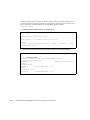
2.5.2.1
Checking the Software Configuration
The following procedure for these checks can be made from any terminal window terminal.
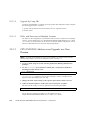
1. Execute the showrev command.
# showrev
The showrev command will print the system configuration information to the screen.
Chapter 2
System Overview and Troubleshooting
2-25
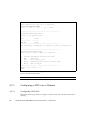
2.5.2.2
Checking the Firmware Configuration
Login authority is required to check the firmware configuration. The following procedure for
these checks can be made from the maintenance terminal:.
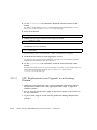
1. Log in to the XSCF.
2. Execute the version command.
XSCF> version
The version command will print the firmware version information to the screen. For
the detailed procedure, see the SPARC Enterprise M3000/M4000/M5000/M8000/M9000
Servers XSCF User’s Guide.
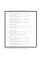
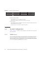
2.5.3
Downloading the Error Log Information
If you want to download the error log information, use the XSCF log fetch function. The
XSCF Unit has an interface with external units so that a service engineer can easily obtain
useful maintenance information such as error logs
Connect the maintenance terminal, and use the CLI or BUI to issue a download instruction to
the maintenance terminal to download Error Log information over the XSCF-LAN.
Note – When the XSCF unit has a redundant configuration, log in also to the standby XSCF
and obtain the log file in the same manner.
2.6
Error Conditions
This section describes error conditions and relevant corrective actions.
This work is explained in the following sections:
■
■
■
Section 2.6.1, “Predictive Self-Healing Tools” on page 2-27
Section 2.6.2, “Monitoring Output” on page 2-28
Section 2.6.3, “Messaging Output” on page 2-30
Details of the fault information, see the SPARC Enterprise
M3000/M4000/M5000/M8000/M9000 Servers XSCF User’s Guide.
See the Oracle Solaris 10 documentation for more information on predictive self-healing.
2-26
SPARC Enterprise M8000/M9000 Servers Service Manual • October 2012
Predictive self-healing is an architecture and methodology for automatically diagnosing,
reporting, and handling software and hardware fault conditions. This new technology lessens
the time required to debug a hardware or software problem and provides the administrator
and technical support with detailed data about each fault.
2.6.1
Predictive Self-Healing Tools
In Oracle Solaris OS, the fault manager runs in the background. If a failure occurs, the
system software recognizes the error and attempts to determine what hardware is faulty. The
software also takes steps to prevent that component from being used until it has been
replaced. Some of the specific activities the software takes include:
■
Receives telemetry information about problems detected by the system software
■
Diagnoses the problems
■
Initiates pro-active self-healing activities. For example, the fault manager can disable
faulty components.
The state of a FRU, group of FRUs, or part of a FRU, that has been isolated because a
fault was detected. The isolation is usually done to prevent possibly faulty components
from affecting other system components. The part that is isolated is not always the faulty
part alone; a normal part may be degraded to isolate the faulty part. If a function required
for the operation of the system is degraded, a system failure may result.
■
When possible, causes the faulty FRU to provide an LED indication of a fault in addition
to populating the system console messages with more details
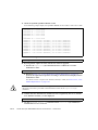
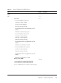
TABLE 2-8 shows a typical message generated when a fault occurs. The message appears on
your console and is recorded in the /var/adm/messages file.
Note – The message in TABLE 2-8 indicates that the fault has already been diagnosed. Any
corrective action that the system can perform has already taken place. If your server is still
running, it continues to run.
Chapter 2
System Overview and Troubleshooting
2-27
TABLE 2-8
Predictive Self Healing Message
Output Displayed
Description
Nov 1 16:30:20 dt88-292 EVENT-TIME: Tue Nov 1 16:30:20 PST 2005
EVENT-TIME: the time stamp of the
diagnosis.
Nov 1 16:30:20 dt88-292 PLATFORM: SUNW,A70, CSN: -, HOSTNAME:
dt88-292
PLATFORM: A description of the
server encountering the problem.
Nov 1 16:30:20 dt88-292 SOURCE: eft, REV: 1.13
SOURCE: Information on the
Diagnosis Engine used to determine
the fault.
Nov 1 16:30:20 dt88-292 EVENT-ID: afc7e660-d609-4b2f-86b8-ae7c6b8d50c4
EVENT-ID: The Universally Unique
event ID for this fault.
Nov 1 16:30:20 dt88-292 DESC:
DESC: A basic description of the
Nov 1 16:30:20 dt88-292 A problem was detected in the PCI-Express subsystem failure.
Nov 1 16:30:20 dt88-292 Refer to http://sun.com/msg/SUN4-8000-0Y for more
information.
WEBSITE: Where to find specific
information and actions for this fault.
Nov 1 16:30:20 dt88-292 AUTO-RESPONSE: One or more device instances may AUTO-RESPONSE: What, if
be disabled
anything, the system did to alleviate
any follow-on issues
Nov 1 16:30:20 dt88-292 IMPACT: Loss of services provided by the device
instances associated with this fault
IMPACT: A description of what that
response might have done.
Nov 1 16:30:20 dt88-292 REC-ACTION: Schedule a repair procedure to replace
the affected device. Use Nov 1 16:30:20 dt88-292 fmdump -v -u EVENT_ID to
identify the device or contact Sun for support.
REC-ACTION: A short description of
what the system administrator should
do.
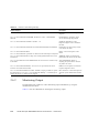
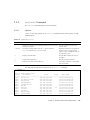
2.6.2
Monitoring Output
To understand error conditions, collect monitoring output information, by using the
commands shown below.
TABLE 2-9 lists the commands for checking the monitoring output.
2-28
SPARC Enterprise M8000/M9000 Servers Service Manual • October 2012
TABLE 2-9
Command
Commands for Checking the Monitoring Output
Operand
showlogs(8) console
Description
XSCF firmware collects console logs of console messages that were output through the
XSCF. This command collects all the console messages displayed to users.
monitor
Logs the messages displayed in the message window of the BUI/CLI.
panic
Saves as panic logs the console logs that are logged when a reset is received after a panic
notification.
ipl
Collects the console data generated during a period from power-on of a domain to
completion of operating system startup (system running).
Chapter 2
System Overview and Troubleshooting
2-29
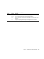
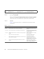
2.6.3
Messaging Output
To understand error conditions, collect messaging output information, by using the
commands shown below.
TABLE 2-10 lists the commands for checking the messaging output.
Commands for Checking the Messaging Output
TABLE 2-10
Command
Operand
Description
showlogs
env
Collects the temperature history log. The server environmental temperature data and
power status are collected at a 10-minute interval. The data is stored for a maximum of
six months.
power
Collects the log of power events and reset events. The target range covers the server,
External I/O Expansion units, and UPSs.
event
Collects the message which accompanies the command or the progress of operation such
as Dynamic Reconfiguration (DR), the status of operation on the operator panel, the event
such as the shut down request to OS due to power failure or abnormal temperature, as
event log. This information is used to analyze faults and investigate the use status of
individual devices at a customer's site, and it is kept as a maintenance work history.
error
Information on the server hardware faults detected by the SCF, POST/OpenBoot PROM,
or ESF machine management and software monitoring error information are logged as
SCF error logs. The showlogs error command can display with hexadecimal codes
the error information stored in the SCF error log and information on faulty components.
fmdump(1M)
fmdump(8)
Hardware and software are automatically diagnosed according to the fault management
architecture (FMA), and the diagnosis results and errors are automatically recorded. The
fmdump command can display the recorded information. It is provided as an Oracle
Solaris OS command and XSCF Shell command. The information can be checked at the
site at the specified URL by using a displayed message ID.
Each error message logged by the predictive self-healing architecture has a code associated
with it as well as a web address that can be followed to get the most up-to-date course of
action for dealing with that error.
Refer to the Oracle Solaris OS documentation for more information on predictive
self-healing.
2.7
LED Error Display
This section explains the LEDs of each FRU that are to be checked when the relevant FRU
is replaced. Each LED can be checked after the door of a cabinet is opened.
2-30
SPARC Enterprise M8000/M9000 Servers Service Manual • October 2012
Whether the state of the entire system is normal can be learned by checking the operator
panel (outside). When an error occurs in an individual hardware component in the system,
the LEDs of the FRU containing the hardware component that has caused the error indicate
that an error has occurred. The LEDs on the operator panel (back) indicate the status of the
operator as a single unit. However, some FRUs like DIMMs do not have LEDs.
Whether a FRU without LEDs is in the normal state can be checked by executing the XSCF
Shell commands showhardconf and ioxadm from a maintenance terminal. For details of
the commands, see the SPARC Enterprise M3000/M4000/M5000/M8000/M9000 Servers
XSCF Reference Manual.
2.7.1
When target FRU is indicated by LEDs
When an error message is displayed at the system console and the cause of the error is in
hardware, a faulty FRU must be removed and replaced. Each FRU is equipped with an LED
to indicate whether an error has occurred in the FRU and an LED to indicate whether the
FRU can be removed. Most FRUs are named READY LED and CHECK LED. In some
cases, names are not indicated but the icons are always printed or icon labels are always
affixed. Such FRUs include the back of the operator panel, XSCFUs, CMUs, XBUs, CLKUs,
FANs, and HDDs.
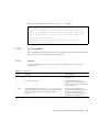
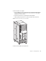
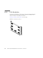
2.7.2
When target FRU is not indicated by LEDs
For some FRUs, the READY LED and CHECK LED are not used as the names of the LEDs
that are checked at replacement. Even in such a case, the same icons as those for the READY
LED and CHECK LED are used so that the meaning of LEDs can be understood. Even if the
names of LEDs are not indicated, the icons are always printed or icon labels are always
affixed.
TABLE 2-11
LED Display That Should Be Checked When a FRU Is Replaced (Common)
LED
Display and Meaning
READY
(green)
Indicates whether the unit is operating (whether it is configured into the system).
Lit
Indicates that the FRU is operating. The FRU cannot be disconnected and removed from
the system. Therefore, the FRU cannot be replaced.
Blinking
Indicates that the FRU is being configured into the system (or, for an XSCFU, being
initialized) or being disconnected from the system. However, for a PSU, it indicates that
the main line switch has been switched on.
Off
Indicates that the FRU is stopped and disconnected from the system. Therefore, the FRU
can be replaced.
Chapter 2
System Overview and Troubleshooting
2-31
TABLE 2-11
LED Display That Should Be Checked When a FRU Is Replaced (Common) (Continued)
LED
Display and Meaning
CHECK
(amber)
Indicates either that the unit contains an error or that the unit is a target device for replacement.
Lit
Indicates that an error has been detected in the hardware of the FRU. (For an HDD, the
LED is lit according to the instruction from the software or middleware.)
Blinking*
Indicates that the FRU is to be replaced.
Off
Indicates that the state of the FRU is normal.
* If the maintenance target component is indicted by a blinking CHECK LED, the LED may be called a locator.
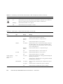
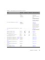
TABLE 2-12
Status Display of LEDs Defined Individually for Each FRU
LED
FRU
Type
Display
Meaning
XSCFU
READY
Lit (green)
Indicates that the XSCFU is in use. In this state, the XSCFU
cannot be removed (cannot be replaced).
Blinking
(green)
Indicates that the XSCFU is being initialized.
Off
Indicates that the XSCFU can be replaced.
Lit (amber)
Indicates that an error was detected in the XSCFU. However,
this LED remains on for a few minutes immediately after
power-on (until the start of initialization). It does not indicate
an error during that time.
Blinking
(amber)
Indicates that the XSCFU is a replacement target.
Off
Indicates that the XSCFU is in the normal state.
Lit (green)
Indicates that the XSCFU is in use (active).
Off
Indicates that the XSCFU is on standby.
Lit (green)
Indicates that communication is being performed through the
Ethernet port (LAN port).
Off
Indicates that no communication is being performed through
the Ethernet port (LAN port).
Lit (amber)
Only for an IOU: Indicates that the communication speed is
1G bps.
Lit (green)
Indicates that the communication speed is 100M bps.
Off
Indicates that the communication speed is 10M bps.
CHECK
ACTIVE
XSCFU and IOU
(display part for
LAN)
ACT
LINK SPEED
2-32
SPARC Enterprise M8000/M9000 Servers Service Manual • October 2012
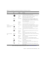
TABLE 2-12
Status Display of LEDs Defined Individually for Each FRU (Continued)
LED
FRU
Type
Display
Meaning
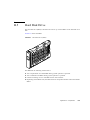
HDD
READY
Lit (green)
Indicates that the HDD is in operation. In this state, the HDD
cannot be removed (cannot be replaced).
Blinking
(green)
Indicates that the HDD is being connected. In this state, the
HDD cannot be removed (cannot be replaced).
Off
Indicates that the HDD can be replaced.
Lit (amber)
Indicates that an error was detected in the HDD. However,
this LED remains on for a few minutes immediately after
power-on (until the start of initialization). It does not indicate
an error during that time.
Blinking
(amber)
Indicates that the HDD is a replacement target.
Off
Indicates that the HDD is in the normal state.
Lit (green)
Indicates that power is being supplied to the PCI card in the
PCI slot. PCI card cannot be removed (cannot be replaced).
Off
Indicates that the PCI card in the PCI slot is stopped. PCI
card can be removed (can be replaced).
Lit (amber)
Indicates that an error occurred in the hardware of the PCI
slot.
Blinking
(amber)
Indicates that the PCI card in this PCI slot is a device to be
replaced.
Off
Indicates that the hardware of the PCI slot is normal.
Lit (green)
Indicates that the power to the system is turned on and being
supplied.
Blinking
(green)
Indicates that power is being supplied to the PSU, but the
PSU is not turned on.
Off
Indicates that power is not being supplied to the PSU.
Lit (amber)
Indicates that an error occurred in the PSU. Maintenance can
be performed.
Off
Indicates that the PSU is normal.
Lit (amber)
Indicates that the rotational speed of the cooling fan in the
PSU is abnormal.
Off
Indicates that the rotational speed of the cooling fan in the
PSU is normal.
OK
CHECK
PCI card
(Power)
(inside an external I/O
expansion unit)
(Attention)
PSU: power supply
unit
POWER
FAIL
PRFL
For the status display of LEDs for the tape drive unit, see TABLE B-2 and TABLE B-3.
Chapter 2
System Overview and Troubleshooting
2-33
2.8
Using the Troubleshooting Commands
After the message in TABLE 2-8 is displayed, you might desire more information about the
fault. For complete information about troubleshooting commands, refer to the Oracle Solaris
OS man pages or the XSCF Shell man pages. This section describes some details of the
following commands:
■
■
■
■
2.8.1
Section 2.8.1,
Section 2.8.2,
Section 2.8.3,
Section 2.8.4,
“Using
“Using
“Using
“Using
the
the
the
the
showlogs Command” on page 2-34
fmdump Command” on page 2-34
fmadm Command” on page 2-35
fmstat Command” on page 2-36
Using the showlogs Command
The showlogs command will display the contents of a specified log in order of timestamp
starting with the oldest date. The showlogs command will display the following logs:
■
■
■
■
■
■
■
■
error log
power log
event log
temperature and humidity record
monitoring message log
console message log
panic message log
IPL message log
XSCF> showlogs error
Dated: Mar 30 12:45:31 JST 2005 Code: 00112233-44556677-8899aabbcceeff0
Status: Alarm
Component: PSU#1,PSU#2
Msg: ACFAIL occurred (ACS=3)(FEP type = A1)
Date: Mar 30 17:45:31 JST 2005 Code: 00112233-44556677-8899aabbcceeff0
Status: Faulted
Component: PSU#1,PSU#2,*
Msg: ACFAIL occurred (ACS=3)(FEP type = A1)
XSCF>0
2.8.2
Using the fmdump Command
The fmdump command can be used to display the contents of any log files associated with
the Oracle Solaris Fault Manager.
2-34
SPARC Enterprise M8000/M9000 Servers Service Manual • October 2012
The fmdump command produces the following output. This example assumes there is only
one fault.
# fmdump
TIME UUID SUNW-MSG-ID
Nov 02 10:04:15.4911 0ee65618-2218-4997-c0dc-b5c410ed8ec2 SUN4-8000-0Y
2.8.3
Using the fmadm Command
This section describes the use of the fmadm command.
The administrator and all service engineers can use the fmadm command. This command can
display and change the system configuration parameters managed by the Oracle Solaris Fault
Manager.
2.8.3.1
fmadm config Command
The fmadm config command outputs the version and status of the diagnostic engine used
by the server. To determine whether the latest diagnostic engine is running, compare the
version with the information on the My Oracle Support website.
# fmadm config
MODULE
cpumem-diagnosis
cpumem-retire
eft
fmd-self-diagnosis
io-retire
syslog-msgs
2.8.3.2
VERSION
1.5
1.0
1.13
1.0
1.0
1.0
STATUS
active
active
active
active
active
active
DESCRIPTION
UltraSPARC-III/IV CPU/Memory Diagnosis
CPU/Memory Retire Agent
eft diagnosis engine
Fault Manager Self-Diagnosis
I/O Retire Agent
Syslog Messaging Agent
fmadm faulty Command
The fmadm faulty command can be used mainly to identify the status of faulty
components.
In the following example, the PCI card is degraded and associated with the following UUID
49847040-ce57-e453-9adc-fe66c7c65384. Also, the "faulted" state may be
displayed.
Chapter 2
System Overview and Troubleshooting
2-35
# fmadm faulty
STATE
RESOURCE / UUID
-----------------------------------------------------degraded dev:////pci@2,600000
49847040-ce57-e453-9adc-fe66c7c65384
Note – The error information remains in the Oracle Solaris OS even when replacement of
the faulty component is completed. Identify the UUID by executing the fmadm faulty
command, and reset the error information by executing the fmadm repair command with
the UUID specified.
2.8.3.3
fmadm repair Command
The fmadm repair command can be used to reset the error information for a faulty
component in the Oracle Solaris OS.
# fmadm repair 49847040-ce57-e453-9adc-fe66c7c65384
fmadm: recorded repair to 3de29de5-6332-ec64-9b49-bacc739fe3c3
Note – The error information remains in the Oracle Solaris OS even when replacement of
the faulty component is completed. Identify the UUID by executing the fmadm faulty
command, and reset the error information by executing the fmadm repair command with
the UUID specified.
2.8.4
Using the fmstat Command
The fmstat command can report statistics associated with the Oracle Solaris Fault
Manager. The fmstat command shows information about DE performance. In the example
below, the eft DE (also seen in the console output) has received an event which it accepted.
A case is "opened" for that event and a diagnosis is performed to "solve" the cause for the
failure.
2-36
SPARC Enterprise M8000/M9000 Servers Service Manual • October 2012
# fmstat
module
ev_recv
cpumem-diagnosis
0
cpumem-retire
0
eft
1
fmd-self-diagnosis
0
io-retire
1
syslog-msgs
1
2.9
ev_acpt
0
0
1
0
0
0
wait
0.0
0.0
0.0
0.0
0.0
0.0
svc_t
0.0
0.0
1191.8
0.0
32.4
0.5
%w
0
0
0
0
0
0
%b
0
0
0
0
0
0
open
0
0
1
0
0
0
solve
0
0
1
0
0
0
memsz
3.0
0
3.3M
0
37b
32b
bufsz
K0
0
11K
0
0
0
Traditional Oracle Solaris Troubleshooting
Commands
These superuser commands can help you determine if you have issues in your workstation, in
the network, or within another server that you are networking with.
The following commands are described in this section:
■
■
■
■
■
■
■
Section 2.9.1,
Section 2.9.2,
Section 2.9.3,
Section 2.9.4,
Section 2.9.5,
Section 2.9.6,
Section 2.9.7,
“iostat Command” on page 2-37
“prtdiag Command” on page 2-39
“prtconf Command” on page 2-41
“netstat Command” on page 2-45
“ping Command” on page 2-46
“ps Command” on page 2-47
“prstat Command” on page 2-48
Most of these commands are located in the /usr/bin or /usr/sbin directories.
2.9.1
iostat Command
The iostat command iteratively reports terminal, drive, and tape I/O activity, as well as
CPU utilization.
Chapter 2
System Overview and Troubleshooting
2-37
2.9.1.1
Options
TABLE 2-13 describes options for the iostat command and how those options can help
troubleshoot the server.
TABLE 2-13
Options for iostat
Option
Description
How It Can Help
No option
Reports status of local I/O devices.
A quick three-line output of device
status.
-c
Reports the percentage of time the system has spent in user mode,
in system mode, waiting for I/O, and idling.
Quick report of CPU status.
-e
Displays device error summary statistics. The total errors, hard
errors, soft errors, and transport errors are displayed.
Provides a short table with
accumulated errors. Identifies suspect
I/O devices.
-E
Displays all device error statistics.
Provides information about devices:
manufacturer, model number, serial
number, size, and errors.
-n
Displays names in descriptive format.
Descriptive format helps identify
devices.
-x
For each drive, reports extended drive statistics. The output is in
tabular form.
Similar to the -e option, but provides
rate information. This helps identify
poor performance of internal devices
and other I/O devices across the
network.
The following example shows output for one iostat command.
# iostat -En
c0t0d0
Soft Errors: 0 Hard Errors: 0 Transport Errors: 0
Model: ST3120026A
Revision: 8.01 Serial No: 3JT4H4C2
Size: 120.03GB <120031641600 bytes>
Media Error: 0 Device Not Ready: 0 No Device: 0 Recoverable: 0
Illegal Request: 0
c0t2d0
Soft Errors: 0 Hard Errors: 0 Transport Errors: 0
Vendor: LITE-ON Product: COMBO SOHC-4832K Revision: O3K1 Serial
No:
Size: 0.00GB <0 bytes>
Media Error: 0 Device Not Ready: 0 No Device: 0 Recoverable: 0
Illegal Request: 0 Predictive Failure Analysis: 0
2-38
SPARC Enterprise M8000/M9000 Servers Service Manual • October 2012
2.9.2
prtdiag Command
The prtdiag command displays configuration and diagnostic information.
The prtdiag command is located in the
/usr/platform/platform-name/sbin/ directory.
Note – The prtdiag command might indicate a slot number different than that identified
elsewhere in this document. This is normal.
2.9.2.1
Options
TABLE 2-14 describes options for the prtdiag command and how those options can help
troubleshooting.
TABLE 2-14
Options for prtdiag
Option
Description
How It Can Help
No option
Lists components.
Identifies CPU information, memory configuration, mounted PCI
cards, OBP version number, mode switch status, and CPU
operational mode.
-v
Verbose mode.
Provides the same information as "no option." Additionally, lists
the detail information of PCI cards.
Chapter 2
System Overview and Troubleshooting
2-39
The following example shows output for the prtdiag command in verbose mode.
# prtdiag -v
System Configuration: Sun Microsystems
System clock frequency: 960 MHz
Memory size: 8192 Megabytes
sun4u SPARC Enterprise M8000 Server
==================================== CPUs ====================================
CPU
CPU
Run
L2$
CPU
CPU
LSB
Chip
ID
MHz
MB
Impl.
Mask
-----------------------------------------------00
0
0, 1, 2, 3, 4, 5, 6, 7
3000
12.0
7
192
01
1
40, 41, 42, 43, 44, 45, 46, 47
3000
12.0
7
192
02
2
80, 81, 82, 83, 84, 85, 86, 87
3000
12.0
7
192
============================ Memory Configuration ============================
LSB
--01
02
Memory
Group
-----A
A
Available
Size
-----------------4096MB
4096MB
Memory
Status
------okay
okay
DIMM
Size
-----1024MB
1024MB
# of
DIMMs
----4
4
Mirror Interleave
Mode
Factor
------- ---------no
2-way
no
2-way
========================= IO Cards =========================
LSB
--00
00
00
Name
-------------scsi
network
network
Model
-----------LSI,1064
N/A
N/A
==================== Hardware Revisions ====================
System PROM revisions:
---------------------OBP 4.24.13 2010/02/08 13:17
=================== Environmental Status ===================
Mode switch is in UNLOCK mode
=================== System Processor Mode ===================
SPARC64-VII mode
2-40
SPARC Enterprise M8000/M9000 Servers Service Manual • October 2012
2.9.3
prtconf Command
Similar to the show-devs command run at the ok prompt, the prtconf command
displays the devices that are configured.
The prtconf command identifies hardware that is recognized by the Oracle Solaris OS. If
hardware is not suspected of being bad yet software applications are having trouble with the
hardware, the prtconf command can indicate if the Oracle Solaris OS software recognizes
the hardware, and if a driver for the hardware is loaded.
2.9.3.1
Options
TABLE 2-15 describes options for the prtconf command and how those options can help
troubleshooting.
TABLE 2-15
Options for prtconf
Option
Description
How It Can Help
No option
Displays the device tree of devices recognized by the OS.
If a hardware device is recognized,
then it is probably functioning
properly. If the message "(driver not
attached)" is displayed for the device
or for a sub-device, then the driver for
the device is corrupt or missing.
-D
Similar to the output of no option, however the device driver is
listed.
Lists the driver needed or used by the
OS to enable the device.
-p
Similar to the output of no option, yet is abbreviated.
Reports a brief list of the devices.
-V
Displays the version and date of the OpenBoot PROM firmware.
Provides a quick check of firmware
version.
Chapter 2
System Overview and Troubleshooting
2-41
The following example shows output for the prtconf command.
# prtconf
System Configuration: Sun Microsystems
Memory size: 32768 Megabytes
System Peripherals (Software Nodes):
sun4u
SUNW,SPARC-Enterprise
scsi_vhci, instance #0
packages (driver not attached)
SUNW,probe-error-handler (driver not attached)
SUNW,builtin-drivers (driver not attached)
deblocker (driver not attached)
disk-label (driver not attached)
terminal-emulator (driver not attached)
obp-tftp (driver not attached)
ufs-file-system (driver not attached)
hsfs-file-system (driver not attached)
chosen (driver not attached)
openprom (driver not attached)
client-services (driver not attached)
options, instance #0
aliases (driver not attached)
memory (driver not attached)
virtual-memory (driver not attached)
pseudo-console, instance #0
nvram (driver not attached)
pseudo-mc, instance #0
pseudo-mc, instance #1
pseudo-mc, instance #2
pseudo-mc, instance #3
cmp (driver not attached)
core (driver not attached)
cpu (driver not attached)
cpu (driver not attached)
core (driver not attached)
cpu (driver not attached)
cpu (driver not attached)
core (driver not attached)
cpu (driver not attached)
cpu (driver not attached)
core (driver not attached)
cpu (driver not attached)
cpu (driver not attached)
2-42
SPARC Enterprise M8000/M9000 Servers Service Manual • October 2012
cmp (driver not attached)
core (driver not attached)
cpu (driver not attached)
cpu (driver not attached)
core (driver not attached)
cpu (driver not attached)
cpu (driver not attached)
core (driver not attached)
cpu (driver not attached)
cpu (driver not attached)
core (driver not attached)
cpu (driver not attached)
cpu (driver not attached)
pci, instance #0
ebus, instance #0
flashprom (driver not attached)
serial, instance #0
scfc, instance #0
panel, instance #0
Chapter 2
System Overview and Troubleshooting
2-43
pci, instance #1
ebus, instance #1
flashprom (driver not attached)
serial, instance #1
scfc, instance #1
panel, instance #1
pci, instance #2
ebus, instance #2
flashprom (driver not attached)
serial, instance #2
scfc, instance #2
panel, instance #2
pci, instance #3
ebus, instance #3
flashprom (driver not attached)
serial, instance #3
scfc, instance #3
panel, instance #3
pci, instance #0
pci, instance #0
pci, instance #1
pci, instance #3
scsi, instance #0
tape (driver not attached)
disk (driver not attached)
sd, instance #1
sd, instance #0 (driver not attached)
sd, instance #2
network, instance #0
network, instance #1 (driver not attached)
pci, instance #4
pci, instance #2
pci, instance #1
pci, instance #2
pci, instance #3
ramdisk-root (driver not attached)
os-io (driver not attached)
iscsi, instance #0
pseudo, instance #0
2-44
SPARC Enterprise M8000/M9000 Servers Service Manual • October 2012
2.9.4
netstat Command
The netstat command displays the network status.
2.9.4.1
Options
TABLE 2-16 describes options for the netstat command and how those options can help
troubleshooting.
TABLE 2-16
Options for netstat
Option
Description
How It Can Help
-i
Displays the interface state, including packets in/out, error in/out,
collisions, and queue.
Provides a quick overview of the
network status.
-i interval
Providing a trailing number with the -i option repeats the
netstat command every interval seconds.
Identifies intermittent or long duration
network events. By piping netstat
output to a file, overnight activity can
be viewed all at once.
-p
Displays the media table.
Provides MAC address for hosts on
the subnet.
-r
Displays the routing table.
Provides routing information.
-n
Replaces host names with IP addresses.
Used when an address is more useful
than a host name.
The following example shows output for the netstat -p command.
# netstat -p
Net to
Device
-----bge0
bge0
bge0
bge0
bge0
bge0
bge0
bge0
bge0
bge0
bge0
Media Table: IPv4
IP Address
---------------------phatair-46
ns-umpk27-02-46
moreair-46
fermpk28a-46
fermpk28as-46
kayakr
matlock
toronto2
tocknett
mpk28-lobby
efyinisedeg
Mask
Flags
Phys Addr
----------------- ----- --------------255.255.255.255
08:00:20:92:4a:47
255.255.255.255
08:00:20:93:fb:99
255.255.255.255
08:00:20:8a:e5:03
255.255.255.255
00:00:0c:07:ac:2e
255.255.255.255
00:50:e2:61:d8:00
255.255.255.255
08:00:20:d1:83:c7
255.255.255.255
SP
00:03:ba:27:01:48
255.255.255.255
08:00:20:b6:15:b5
255.255.255.255
08:00:20:7c:f5:94
255.255.255.255
08:00:20:a6:d5:c8
255.255.255.255
08:00:20:8d:6a:80
Chapter 2
System Overview and Troubleshooting
2-45
bge0
bge0
bge0
froggy
d-mpk28-46-245
224.0.0.0
2.9.5
255.255.255.255
255.255.255.255
240.0.0.0
SM
08:00:20:73:70:44
00:10:60:24:0e:00
01:00:5e:00:00:00
ping Command
The ping command sends ICMP ECHO_REQUEST packets to network hosts. Depending
on how the ping command is configured, the output displayed can identify troublesome
network links or nodes. The destination host is specified in the variable hostname.
2.9.5.1
Options
TABLE 2-17 describes options for the ping command and how those options can help
troubleshooting.
Options for ping
TABLE 2-17
Option
Description
How It Can Help
hostname
The probe packet is sent to hostname and returned.
Verifies that a host is active on the
network.
-g hostname
Forces the probe packet to route through a specified gateway.
By identifying different routes to the
target host, those individual routes can
be tested for quality.
-i interface
Designates which interface to send and receive the probe packet
through.
Enables a simple check of secondary
network interfaces.
-n
Replaces host names with IP addresses.
Used when an address is more
beneficial than a host name.
-s
Pings continuously in one-second intervals. Ctrl-C aborts. Upon
abort, statistics are displayed.
Helps identify intermittent or
long-duration network events. By
piping ping output to a file, activity
overnight can later be viewed at once.
-svR
Displays the route the probe packet followed in one second
intervals.
Indicates probe packet route and
number of hops. Comparing multiple
routes can identify bottlenecks.
2-46
SPARC Enterprise M8000/M9000 Servers Service Manual • October 2012
The following example shows output for the ping -s command.
# ping -s teddybear
PING teddybear: 56 data bytes
64 bytes from teddybear (192.146.77.140): icmp_seq=0.
64 bytes from teddybear (192.146.77.140): icmp_seq=1.
64 bytes from teddybear (192.146.77.140): icmp_seq=2.
^C
----teddybear PING Statistics---3 packets transmitted, 3 packets received, 0% packet
round-trip (ms) min/avg/max = 0/0/1
2.9.6
time=1. ms
time=0. ms
time=0. ms
loss
ps Command
The ps command lists the status of processes. Using options and rearranging the command
output can assist in determining the resource allocation.
2.9.6.1
Options
TABLE 2-18 describes options for the ps command and how those options can help
troubleshooting.
TABLE 2-18
Options for ps
Option
Description
How It Can Help
-e
Displays information for every process.
Identifies the process ID and the
executable.
-f
Generates a full listing.
Provides the following process
information: user ID, parent process
ID, time when executed, and the path
to the executable.
-o option
Enables configurable output. The pid, pcpu, pmem, and comm
options display process ID, percent CPU consumption, percent
memory consumption, and the responsible executable,
respectively.
Provides only most important
information. Knowing the percentage
of resource consumption helps
identify processes that are affecting
performance and might be hung.
Chapter 2
System Overview and Troubleshooting
2-47
The following example shows output for one ps command.
# ps -eo pcpu,pid,comm|sort -rn
1.4 100317 /usr/openwin/bin/Xsun
0.9 100460 dtwm
0.1 100677 ps
0.1 100600 ksh
0.1 100591 /usr/dt/bin/dtterm
0.1 100462 /usr/dt/bin/sdtperfmeter
0.1 100333 mibiisa
%CPU
PID COMMAND
0.0 100652 /bin/csh
. . .
Note – When using sort with the -r option, the column headings are printed so that the
value in the first column is equal to zero.
2.9.7
prstat Command
The prstat utility iteratively examines all active processes and reports statistics based on the
selected output mode and sort order. The prstat command provides output similar to the
ps command.
2-48
SPARC Enterprise M8000/M9000 Servers Service Manual • October 2012
2.9.7.1
Options
TABLE 2-19 describes options for the prstat command and how those options can help
troubleshooting.
TABLE 2-19
Options for prstat
Option
Description
How It Can Help
No option
Displays a sorted list of the top processes that are consuming the Output identifies process ID, user ID,
memory used, state, CPU
most CPU resources. List is limited to the height of the terminal
window and the total number of processes. Output is automatically consumption, and command name.
updated every five seconds. Ctrl-C aborts.
-n number
Limits output to number of lines.
Limits amount of data displayed and
identifies primary resource
consumers.
-s key
Permits sorting list by key parameter.
Useful keys are cpu (default), time,
and size.
-v
Verbose mode.
Displays additional parameters.
The following example shows output for the prstat command.
# prstat -n 5 -s size
PID
USERNAME SIZE
RSS STATE PRI NICE TIME
CPU
PROCESS/NLWP
100524 mm39236
28M
21M sleep 48
0
0:00.26 0.3% maker6X.exe/1
100317 root
28M
69M sleep 59
0
0:00.26 0.7% Xsun/1
100460 mm39236
11M 8760K sleep 59
0
0:00.03 0.0% dtwm/8
100453 mm39236 8664K 4928K sleep 48
0
0:00.00 0.0% dtsession/4
100591 mm39236 7616K 5448K sleep 49
0
0:00.02 0.1% dtterm/1
Total: 65 processes, 159 lwps, load averages: 0.03, 0.02, 0.04
Chapter 2
System Overview and Troubleshooting
2-49
2-50
SPARC Enterprise M8000/M9000 Servers Service Manual • October 2012
C H A PT E R
3
Periodic Maintenance
Caution – The information in this chapter and subsequent chapters is intended for use by
authorized service engineers only. For non-authorized field engineers, this information is for
reference only.
This chapter explains the maintenance work that must be performed regularly regardless of
whether a problem has occurred. The actual work is limited to preventing dust in the
environment from creating pollution.
This information is explained in the following sections:
■
■
■
Section 3.1, “Cleaning a Tape Drive Unit” on page 3-1
Section 3.2, “Cleaning an Air Filter (Server)” on page 3-2
Section 3.3, “Cleaning an Air Filter (I/O Unit)” on page 3-5
The high-end server is equipped with air filters at the bottom of the cabinet. These air filters
filter out dust particles from the air that the fans suck in from the floor into the cabinet. If the
filters become clogged, the ventilation volume is reduced and the temperature rises, leading
to problems. Although the frequency of cleaning varies with the operating environment, the
air filters must be cleaned on a regular basis to ensure that they do not become clogged with
dust. Each I/O unit also has air filters. Clean them at the same time that the air filters of the
server are cleaned.
When the service life expiration date of an air filter has already passed, replace it by
referring to the air filter cleaning procedure.
3.1
Cleaning a Tape Drive Unit
The head in a tape drive unit must be cleaned regularly.
3-1
Each tape drive unit used for operation must be cleaned once every 24 hours of operation.
Even tape drive units not used for operation must be cleaned once every month.
For cleaning, use a cleaning cassette. Consider the product life of the cleaning cassette and
manage the number of uses.
Although cleaning work can be performed in either hot or cold system maintenance mode,
the server power must be on when a cleaning cassette is used. The cleaning procedure is as
follows.
1. If a tape cassette has been inserted in the tape drive unit, remove it from the unit.
2. While holding the cleaning cassette with the
the tape drive unit slot.
mark side facing right, insert it into
Head cleaning begins automatically.
3. The cleaning cassette is automatically ejected when cleaning is completed. Remove it
from the slot.
4. To use the tape cassette that was removed in Step 1, reinsert it into the tape drive
unit.
5. Confirm that the tape drive unit is in the normal state.
At this point, head cleaning is finished.
If one of the following problems occurs, replace the cleaning cassette immediately:
■
The cleaning cassette is not automatically ejected within one minute after being inserted.
■
The tape is fully wound on the take-up reel on the right side. (The cassette can no longer
be reused.)
Use only specified cleaning cassettes.
Note – Contact your sales representative for tape drive unit options on M8000/M9000
servers.
3.2
Cleaning an Air Filter (Server)
An air filter may be cleaned while power to the server is on. Although the air filters must be
cleaned once a year, be sure to clean them if they become visibly dirty, even if they are not
scheduled for cleaning.
A high-end server cabinet is equipped with a total of six air filters: three at the front and
three at the rear at the bottom.
3-2
SPARC Enterprise M8000/M9000 Servers Service Manual • October 2012
Note – One concern about cleaning the air filters while power to the server is on is that
dislodged dust may be sucked inside the system when the air filters are pulled out. Therefore,
gently and slowly pull them out. Complete the cleaning as quickly as possible.
Caution – When using a vacuum cleaner to clean the air filters, use it outside the computer
room. Using a vacuum cleaner inside the computer room might result in a server failure.
Because the structure and the mounting environment of air filters are the same, the
descriptions in the figures covering filter cleaning refer to, as an example, the air filters at the
front of each model.
Cleaning an Air Filter (M8000 Server)
1. Unlock and open the front and rear doors of the server. (See Chapter 5)
2. Using a Phillips screwdriver, loosen the screw securing the fixing bracket of an air
filter, and turn the bracket so that it faces downward.
Chapter 3
Periodic Maintenance
3-3
FIGURE 3-1
Removing Air Filters (Example for the M8000)
Fixing bracket (x3)
3. Pull out all of the air filters.
4. Use a cleaner to remove dust from the air filters. Attach a brush to the tip of the
cleaner, and clean both sides of the filters.
5. Restore each air filter to its original location and orientation, which means the knob
is on the side closest to you and the arrow on the label points up (the latticework
faces upward).
6. When this restoring work is completed for all the air filters, turn the fixing brackets
of the air filters until they face upward, and then tighten the screws firmly with the
Phillips screwdriver. Finally, close the front and rear doors of the server.
3-4
SPARC Enterprise M8000/M9000 Servers Service Manual • October 2012
Cleaning an Air Filter (M9000 Server)
This filter cleaning procedure applies to both high-end servers.
FIGURE 3-2
Removing of Air Filters (Example Using the M9000 Base Cabinet)
Fixing bracket (x3)
3.3
Cleaning an Air Filter (I/O Unit)
If your I/O unit has the air filters, do the cleaning. Clean the air filters at the same time that
the air filters of the server are cleaned.
Caution – If you must use a vacuum cleaner for this work, use it outside the computer
room. Do not use it inside the computer room. Using a vacuum cleaner inside the computer
room may result in a server failure.
Chapter 3
Periodic Maintenance
3-5
The cleaning procedure is as follows.
1. Loosen the screws securing the filter cover, and remove the filter cover.
2. Pull out the air filter from the filter cover.
FIGURE 3-3
Removing of Air Filters (I/O Unit)
3. Use a vacuum cleaner to remove dust from the air filter.
4. After the cleaning is completed, follow the removal procedure in reverse order to
mount it.
3-6
SPARC Enterprise M8000/M9000 Servers Service Manual • October 2012
C H A PT E R
4
FRU Replacement Preparation
This chapter explains the required basic operations for replacing components, in the
following sections:
■
■
■
■
■
■
■
Section 4.1,
Section 4.2,
Section 4.3,
Section 4.4,
Section 4.5,
Section 4.6,
Section 4.7,
“Types of Replacement Procedures” on page 4-2
“Active Replacement” on page 4-3
“Hot Replacement” on page 4-14
“Cold Replacement” on page 4-20
“Power-On/Off of Main Line Switch” on page 4-27
“Emergency Switch-Off” on page 4-37
“Cable Routing of the M8000 Server” on page 4-37
When actually performing the work of replacing a component, use the operator panel and the
maintenance terminal by referring to the operator panel display, maintenance terminal
display, and the LED display of the component.
Depending on the target component, the server must be powered off or a domain must be
stopped.
For the LED display of each component, see Section 2.7, “LED Error Display” on page 2-30.
Three replacement types are defined for judging whether power-off of the server or stopping
a domain is necessary: active replacement, hot replacement, and cold replacement. See
Part II. For information on the swapping types of each component, see Appendix B.
Note – Some of the XSCF functions have restrictions on their use. Register the necessary
login privileges for each field engineer in advance. Field engineers cannot use functions that
have not been registered for them. The system administrator sets and changes the users and
their privileges. For details, see the SPARC Enterprise M3000/M4000/M5000/M8000/M9000
Servers XSCF User’s Guide.
Power-on and power-off of the server and emergency power-off are explained in the last part
of this chapter.
■
■
Section 4.5, “Power-On/Off of Main Line Switch” on page 4-27
Section 4.6, “Emergency Switch-Off” on page 4-37
4-1
4.1
Types of Replacement Procedures
The three types of replacement procedures explained below are supported for FRU
replacement. Choose the most suitable replacement procedure according to the customer's
system environment.
■
Active replacement
A target FRU is operated while the Oracle Solaris OS of the domain to which the FRU
belongs is operating. The target FRU is operated by using Oracle Solaris OS commands or
XSCF commands. Because the power supply unit (PSU) and fan unit (FAN) do not belong to
any domain, they are operated by using XSCF commands regardless of the operating state of
the Oracle Solaris OS.
Note – The hard disk drive will have a redundant configuration by setting the mirroring.
Note – If a hard disk drive is a nonmirrored boot device, it must be replaced according to
the cold replacement procedure.
Note – If a hard disk drive is in a mirrored configuration, active replacement can be
performed on the failed drive because the mirrored hard disk drive continues to be online and
functioning. The hard disk replacement procedure varies by the mirroring configuration
method. When it is configured with hardware RAID, see the SPARC Enterprise
M3000/M4000/M5000/M8000/M9000 Servers Administration Guide. When it is configured
with software RAID, see the manuals for the software in use.
Note – Hardware RAID is supported only on the M8000/M9000 servers on which a
RAID-capable onboard device card (IOUA) is mounted. The RAID-capable IOUA requires a
minimum XSCF firmware with applicable Oracle Solaris OS patches. See the latest Product
Notes for this information.
Note – When the onboard device card is RAID-capable, the showhardconf(8) command
displays Type 2 in the output.
PCI#0 Name_Property:pci; Card_Type:IOUA;
+ Serial:PP0611T826 ; Type:2;
+ FRU-Part-Number:CA21138-B84X 010AE/371-5000-05
4-2
SPARC Enterprise M8000/M9000 Servers Service Manual • October 2012
;
■
Hot replacement
A target FRU is operated while the domain to which the FRU belongs is stopped.
Depending on the target FRU, there are two cases as follows:
■
■
Operated with XSCF commands.
■
Operated directly, not by using XSCF commands.
Cold replacement
After all the domains are stopped and then the server is powered off, a FRU is operated.
Note – To activate a hardware RAID boot volume after replacing the RAID-capable IOUA
on an M8000/M9000 server, see Section 13.5, “Reactivating a Hardware RAID Boot
Volume” on page 13-25.
Note – Do not operate a target FRU while the OpenBoot PROM is running (the ok prompt
is displayed). After stopping the relevant domain (power-off) or starting the Oracle Solaris
OS, operate the target FRU.
4.2
Active Replacement
In active replacement the Oracle Solaris OS must be configured to allow the component to be
replaced. Active replacement has four stages:
■
■
■
■
Section 4.2.1,
Section 4.2.2,
Section 4.2.3,
Section 4.2.4,
“Disconnecting a FRU from a Domain” on page 4-4
“Disconnecting and Replacing a FRU” on page 4-6
“Configuring a FRU into a Domain” on page 4-8
“Confirming the Hardware” on page 4-9
Note – If a hard disk drive is a nonmirrored boot device, it must be replaced according to
the cold replacement procedure.
Note – If a hard disk drive is in a mirrored configuration, active replacement can be
performed on the failed drive because the mirrored hard disk drive continues to be online and
functioning.
Chapter 4
FRU Replacement Preparation
4-3
4.2.1
Disconnecting a FRU from a Domain
4.2.1.1
Disconnecting a CMU/IOU
Perform the following procedure to disconnect a CMU or IOU when the Oracle Solaris OS is
operating:
1. Checking resources
Check the resources that are connected to a CMU or IOU to be disconnected, and verify
that the system is not affected when it is disconnected.
2. Disconnecting from the domain
To disconnect the CMU or IOU from the domain, enter the following command from the
terminal that is connected to the XSCF:
XSCF> deleteboard 01-0
The system administrator permission is required for executing this command.
4.2.1.2
Disconnecting a PCI card
Caution – Before you remove the PCI cassette, make sure that there is no activity on the
card in the cassette.
Caution – In the PCI cassette part, when removing cables such as LAN cable, if your
finger can't reach the latch lock of the connector, press the latch with a flathead screwdriver
to remove the cable. Forcing your finger into the clearance can cause damage to the PCI
card.
4-4
SPARC Enterprise M8000/M9000 Servers Service Manual • October 2012
1. From the Oracle Solaris OS use the cfgadm command to get the component status:
# cfgadm
AP_ID
...
iou#0-pci#1
iou#0-pci#2
iou#0-pci#3
iou#0-pci#4
Type
Receptacle
Occupant
Condition
unknown
unknown
etherne/hp
fibre/hp
empty
empty
connected
connected
unconfigured
unconfigured
configured
configured
unknown
unknown
ok
ok
AP_ID is comprised of the IOU number (iou#0 or iou#1) and the PCI cassette slot number
(pci#1, pci#2, pci#3, pci#4)
2. Use the cfgadm command to unconfigure the component from the hardware:
# cfgadm -c unconfigure AP_ID
where AP_ID is the IOU and PCI card as shown in the output of cfgadm.
3. Use the cfgadm command to stop supplying power to the component:
# cfgadm -c disconnect AP_ID
where AP_ID is the IOU and PCI card as shown in the output of cfgadm.
4. Use the cfgadm command to confirm the component from the domain is now
disconnected and unconfigured:
# cfgadm
AP_ID
...
iou#0-pci#1
iou#0-pci#2
iou#0-pci#3
iou#0-pci#4
Type
Receptacle
Occupant
Condition
unknown
unknown
etherne/hp
fibre/hp
empty
empty
disconnected
connected
unconfigured
unconfigured
unconfigured
configured
unknown
unknown
ok
ok
Chapter 4
FRU Replacement Preparation
4-5
4.2.2
Disconnecting and Replacing a FRU
1. From the XSCF Shell prompt, use the replacefru command:
XSCF> replacefru
---------------------------------------------------------------Maintenance/Replacement Menu
Please select a type of FRU to be replaced.
1.
2.
3.
4.
5.
CMU/IOU
FAN
PSU
XSCFU
DDC_A
(CPU Memory Board Unit/IO Unit)
(Fan Unit)
(Power Supply Unit)
(Extended System Control Facility Unit)
(DDC for BP_A)
---------------------------------------------------------------Select [1-5|c:cancel] :
Note – DDC_A is displayed only for the M8000 server.
4-6
SPARC Enterprise M8000/M9000 Servers Service Manual • October 2012
The command is menu-driven. The example continues using a FAN unit.
Select [1-5|c:cancel] :2
--------------------------------------------------Maintenance/Replacement Menu
Please select a FAN to be replaced.
No. FRU
Status
--- --------------- -----------------1.
FAN_A#0
Normal
2.
FAN_A#1
Normal
3.
FAN_A#2
Normal
4.
FAN_A#3
Normal
5.
FAN_B#0
Normal
6.
FAN_B#1
Normal
7.
FAN_B#2
Normal
8.
FAN_B#3
Normal
9.
FAN_B#4
Normal
10. FAN_B#5
Normal
11. FAN_B#6
Not installed
12. FAN_B#7
Not installed
--------------------------------------------------Select [1-12|b:back] :1
You are about to replace FAN_A#0.
Do you want to continue?[r:replace|c:cancel] :r
Please confirm the Check LED is blinking.
If this is the case, please replace FAN_A#0.
After replacement has been completed, please select[f:finish] :f
The replacefru command will automatically test the status of the component after the
disconnecting off and replace has finished.
Chapter 4
FRU Replacement Preparation
4-7
Diagnostic tests for FAN_A#0 have started.
[This operation may take up to 2 minute(s)]
(progress scale reported in seconds)
0..... 30..... 60..... 90.....done
-------------------------------------------------Maintenance/Replacement Menu
Status of the replaced unit.
FRU
Status
------------- -------FAN_A#0
Normal
-------------------------------------------------The replacement of FAN_A#0 has completed, normally.[f:finish] :f
-------------------------------------------------Maintenance/Replacement Menu
Please select a type of FRU to be replaced.
1. CMU/IOU (CPU Memory Board Unit/IO Unit)
2. FAN
(Fan Unit)
3. PSU
(Power Supply Unit)
4. XSCFU
(Extended System Control Facility Unit)
5. DDC_A
(DDC for BP_A)
-------------------------------------------------Select [1-5|c:cancel] : C
XSCF>
When the tests are complete the program will return to the original menu. Select cancel to
return to the XSCF Shell prompt.
Note – The display may vary depending on the XCP version.
4.2.3
Configuring a FRU into a Domain
4.2.3.1
Configuring CMU/IOU
Perform the following procedure to configure a CMU or IOU when the Oracle Solaris OS is
operating:
4-8
SPARC Enterprise M8000/M9000 Servers Service Manual • October 2012
1. Configuring into a domain
To configure CMU or IOU into the domain, enter the following command from the
terminal that is connected to the XSCF:
XSCF> addboard -c configure -d 0 00-0
The system administrator permission is required for executing this command.
2. Checking resources
Log in to the XSCF and execute the showboards command to verify that the target
CMU or IOU has been correctly configured.
4.2.3.2
Configuring a PCI card
1. From the Oracle Solaris OS, use the cfgadm command to configure and connect the
component to the domain:
# cfgadm -c configure AP_ID
where AP_ID is the IOU and PCI card as shown in the output of cfgadm.
2. Use the cfgadm command to confirm the component is now connected and
configured:
# cfgadm
AP_ID
..
iou#0-pci#1
iou#0-pci#2
iou#0-pci#3
iou#0-pci#4
4.2.4
Type
unknown
unknown
etherne/hp
fibre/hp
Receptacle
Occupant
Condition
empty
empty
connected
connected
unconfigured
unconfigured
configured
configured
unknown
unknown
ok
ok
Confirming the Hardware
1. Confirm that the replacement components are normal by using the showhardconf
or showstatus command of XSCF.
Unless "*" is displayed for a replacement CMU, CPU, or DIMM, it is operating normally.
Note – The display may vary depending on the XCP version.
For details of the showhardconf command and showstatus command, see the
SPARC Enterprise M3000/M4000/M5000/M8000/M9000 Servers XSCF User’s Guide, the
SPARC Enterprise M3000/M4000/M5000/M8000/M9000 Servers XSCF Reference
Manual, or the man page.
Chapter 4
FRU Replacement Preparation
4-9
XSCF> showhardconf
SPARC Enterprise M9000;
+ Serial:PA30601004; Operator_Panel_Switch:Locked;
+ Power_Supply_System:Single-1Phase; Ex:Single-1Phase; SCF-ID:XSCF#0;
+ System_Power:On; System_Phase:Cabinet Power On;
Domain#0 Domain_Status:Running;
CMU#0 Status:Normal; Ver:8301h; Serial:PP0616B579 ;
+ FRU-Part-Number:CCA06620-D004 B0
/371-4930-02
;
+ Memory_Size:128 GB;
+ Type:C;
CPUM#0-CHIP#0 Status:Normal; Ver:0a01h; Serial:PP091505ZY ;
+ FRU-Part-Number:CA06620-D061 B1
/371-4929-02
+ Freq:3.000 GHz; Type:48;
+ Core:4; Strand:2;
CPUM#1-CHIP#0 Status:Normal; Ver:0a01h; Serial:PP091505ZW ;
+ FRU-Part-Number:CA06620-D061 B1
/371-4929-02
+ Freq:3.000 GHz; Type:48;
+ Core:4; Strand:2;
CPUM#2-CHIP#0 Status:Normal; Ver:0a01h; Serial:PP0915060H ;
+ FRU-Part-Number:CA06620-D061 B1
/371-4929-02
+ Freq:3.000 GHz; Type:48;
+ Core:4; Strand:2;
CPUM#3-CHIP#0 Status:Normal; Ver:0a01h; Serial:PP09150603 ;
+ FRU-Part-Number:CA06620-D061 B1
/371-4929-02
+ Freq:3.000 GHz; Type:48;
+ Core:4; Strand:2;
MEM#00A Status:Normal;
+ Code:7f7ffe00000000004aEBE41RE4ABHA-5C-E 3020-22211d88;
+ Type:4B; Size:4 GB;
MEM#00B Status:Normal;
+ Code:7f7ffe00000000004aEBE41RE4ABHA-5C-E 3020-2a002a55;
+ Type:4B; Size:4 GB;
:
MEM#33A Status:Normal;
+ Code:ce0000000000000001M3 93T5168AZ0-CD5 3041-741a8ea1;
+ Type:4B; Size:4 GB;
4-10
SPARC Enterprise M8000/M9000 Servers Service Manual • October 2012
;
;
;
;
Output for the showhardconf command (Continued)
MEM#33B Status:Normal;
+ Code:ce0000000000000001M3 93T5168AZ0-CD5 3041-741a8ed3;
+ Type:4B; Size:4 GB;
:
CMU#2 Status:Normal; Ver:8301h; Serial:PP0618K472 ;
+ FRU-Part-Number:CA06620-D004 B0
/371-4930-02
;
+ Memory_Size:32 GB;
+ Type:C;
CPUM#0-CHIP#0 Status:Normal; Ver:0a01h; Serial:PP0608J517 ;
+ FRU-Part-Number:CA06620-D061 B1
/371-4929-02
+ Freq:3.000 GHz; Type:48;
+ Core:4; Strand:2;
CPUM#1-CHIP#0 Status:Normal; Ver:0a01h; Serial:PP0620P552 ;
+ FRU-Part-Number:CA06620-D061 B1
/371-4929-02
+ Freq:3.000 GHz; Type:48;
+ Core:4; Strand:2;
CPUM#2-CHIP#0 Status:Normal; Ver:0a01h; Serial:PP0631Q396 ;
+ FRU-Part-Number:CA06620-D061 B1
/371-4929-02
+ Freq:3.000 GHz; Type:48;
+ Core:4; Strand:2;
CPUM#3-CHIP#0 Status:Normal; Ver:0a01h; Serial:PP0629H443 ;
+ FRU-Part-Number:CA06620-D061 B1
/371-4929-02
+ Freq:3.000 GHz; Type:48;
+ Core:4; Strand:2;
MEM#00A Status:Normal;
+ Code:7f7ffe00000000004aEBE10RD4AGFA-5C-E 3020-221d6855;
+ Type:1A; Size:1 GB;
MEM#00B Status:Normal;
+ Code:7f7ffe00000000004aEBE10RD4AGFA-5C-E 3020-221fcdb7;
+ Type:1A; Size:1 GB;
:
MEM#33A Status:Normal;
+ Code:7f7ffe00000000004aEBE10RD4AGFA-5C-E 3020-221d678b;
+ Type:1A; Size:1 GB;
MEM#33B Status:Normal;
+ Code:2cffffffffffffff0818HTF12872Y-53EB3 0300-69aedd7a;
+ Type:1A; Size:1 GB;
CMU#3 Status:Normal; Ver:8301h; Serial:PP0638F192 ;
+ FRU-Part-Number:CA06620-D004 B0
/371-4930-02
;
+ Memory_Size:64 GB;
+ Type:C;
CPUM#0-CHIP#0 Status:Normal; Ver:0a01h; Serial:PP0631P606 ;
+ FRU-Part-Number:CA06620-D061 B1
/371-4929-02
+ Freq:3.000 GHz; Type:48;
+ Core:4; Strand:2;
Chapter 4
;
;
;
;
;
FRU Replacement Preparation
4-11
Output for the showhardconf command (Continued)
CPUM#1-CHIP#0 Status:Normal; Ver:0a01h; Serial:PP0630M355 ;
+ FRU-Part-Number:CA06620-D061 B1
/371-4929-02
;
+ Freq:3.000 GHz; Type:48;
+ Core:4; Strand:2;
CPUM#2-CHIP#0 Status:Normal; Ver:0a01h; Serial:PP0628D036 ;
+ FRU-Part-Number:CA06620-D061 B1
/371-4929-02
;
+ Freq:3.000 GHz; Type:48;
+ Core:4; Strand:2;
CPUM#3-CHIP#0 Status:Normal; Ver:0a01h; Serial:PP0630M365 ;
+ FRU-Part-Number:CA06620-D061 B1
/371-4929-02
;
+ Freq:3.000 GHz; Type:48;
+ Core:4; Strand:2;
MEM#00A Status:Normal;
+ Code:7f7ffe00000000004aEBE10RD4AGFA-5C-E 3020-221d6855;
+ Type:1A; Size:1 GB;
MEM#00B Status:Normal;
+ Code:7f7ffe00000000004aEBE10RD4AGFA-5C-E 3020-221fcdb7;
+ Type:1A; Size:1 GB;
:
IOU#0 Status:Normal; Ver:0101h; Serial:PP0640Q984 ;
+ FRU-Part-Number:CA06620-D102 B1
/371-2217-02
;
+ Type:A;
PCI#0 Name_Property:pci; Card_Type:IOUA;
+ Serial:PP0611T826 ; Type:2;
+ FRU-Part-Number:CA21138-B84X 010AE/371-5000-05
;
PCI#1 Status:Normal; Name_Property:LSILogic,sas; Card_Type:Other;
+ Serial:0000004; Type:F20;
+ FRU-Part-Number:5111500-01;
IOU#1 Status:Normal; Ver:0101h; Serial:PP072102UM ;
+ FRU-Part-Number:CA06620-D102 B1
/371-2217-02
;
+ Type:A;
PCI#0 Name_Property:pci; Card_Type:IOUA;
+ Serial:PP0611T825 ; Type:2;
+ FRU-Part-Number:CA21138-B84X 010AE/371-5000-05
;
IOU#2 Status:Normal; Ver:4201h; Serial:PP0727053S ;
+ FRU-Part-Number:CA06620-D103 A0
/371-4931-01 ;
+ Type:B;
PCI#4 Name_Property:pci; Card_Type:IOUA;
+ Serial:PP0611T825 ; Type:2;
+ FRU-Part-Number:CA21138-B84X 010AE/371-5000-05
;
:
XSCFU_B#0 Status:Normal,Active; Ver:0201h; Serial:PP080600DW ;
+ FRU-Part-Number:CA06620-D342 C0
/371-2228-02
;
:
XBU_B#0 Status:Normal; Ver:0201h; Serial:PP0641X324 ;
+ FRU-Part-Number:CA06620-D302 C1
/371-2240-03
;
:
4-12
SPARC Enterprise M8000/M9000 Servers Service Manual • October 2012
Output for the showhardconf command (Continued)
CLKU_B#0 Status:Normal; Ver:0201h; Serial:PP0542M679 ;
+ FRU-Part-Number:CA06620-D322 C1
/371-2230-03
:
OPNL#0 Status:Normal; Ver:0101h; Serial:PP06058246 ;
+ FRU-Part-Number:CA06620-D382 A2
/371-2239-01
PSU#0 Status:Normal; Serial:FA11155187;
+ FRU-Part-Number:CA01022-0690 20H /371-2219-08
;
+ Power_Status:On;
:
FANBP_A#0 Status:Normal; Ver:0101h; Serial:PP0607D266 ;
+ FRU-Part-Number:CA21128-B71X 011AE/371-2222-05
FAN_A#0 Status:Normal; Serial:PA0605B287;
+ FRU-Part-Number:CA06622-D012 A5
/371-2237-01
:
FAN_A#15 Status:Normal; Serial:PA0605B303;
+ FRU-Part-Number:CA06622-D012 A5
/371-2237-01
:
FANBP_B#0 Status:Normal; Ver:0201h; Serial:PP0607D270 ;
+ FRU-Part-Number:CA21128-B72X 011AE/371-2223-05
FAN_A#4 Status:Normal; Serial:PA0605B297;
+ FRU-Part-Number:CA06622-D012 A5
/371-2237-01
:
FAN_A#9 Status:Normal; Serial:PA0605B300;
+ FRU-Part-Number:CA06622-D012 A5
/371-2237-01
:
SWBP#0 Status:Normal; Ver:0101h; Serial:PP0607E759 ;
+ FRU-Part-Number:CA20397-B57X 022AG/371-2243-01
MEDBP#0 Status:Normal; Ver:0101h; Serial:PP06058497 ;
+ FRU-Part-Number:CA20397-B56X 005AA/371-2244-01
;
;
;
;
;
;
;
;
;
;
2. Verify the status LEDs on the PCI cassette.
The POWER LED should be lit and the CHECK LED should be off.
Note – If an XSCF failover occurs while executing the addfru, deletefru or
replacefru command, the addition, removal or replacement of FRUs may not have been
completed successfully. In such case, log in again to the active XSCF to confirm that the
addition, removal or replacement of FRUs was successfully completed. If the addition,
removal or replacement of the FRUs was not completed successfully, re-execute the
following commands in the manner described:
- For addfru command execution, execute the deletefru command for the relevant
FRU, and then re-execute the addfru command.
- For deletefru command execution, re-execute the deletefru command for the
relevant FRU.
- For replacefru command execution, re-execute the replacefru command for the
relevant FRU.
Chapter 4
FRU Replacement Preparation
4-13
4.3
Hot Replacement
In hot replacement the Oracle Solaris OS does not need to be configured to allow the
component to be replaced. The domain might need to be stopped and restarted in the case of
CD-RW/DVD-RW drive unit or tape drive units.
4.3.1
■
Section 4.3.1, “Disconnecting and Replacing a FRU” on page 4-14
■
Section 4.3.2, “Confirming the Hardware” on page 4-17
Disconnecting and Replacing a FRU
1. From the XSCF Shell prompt, specify the domain, and execute the poweroff
command.
Example: In case you specify Domain ID 0
XSCF> poweroff -d 0
2. From the XSCF Shell prompt, execute the replacefru command:
XSCF> replacefru
--------------------------------------------------Maintenance/Replacement Menu
Please select a type of FRU to be replaced.
1. CMU/IOU(CPU Memory Board Unit/IO Unit)
2. FAN(Fan Unit)
3. PSU(Power Supply Unit)
4. XSCFU(Extended System Control Facility Unit)
5. DDC_A(DDC for BP_A)
--------------------------------------------------Select [1-5|c:cancel] :
Note – DDC_A is displayed only for the M8000 server.
4-14
SPARC Enterprise M8000/M9000 Servers Service Manual • October 2012
The command is menu-driven. The example continues using a FAN unit.
Select [1,2|c:cancel] :1
--------------------------------------------------Maintenance/Replacement Menu
Please select a FAN to be replaced.
No. FRU
Status
--- --------------- -----------------1. FAN_A#0
Normal
2. FAN_A#1
Normal
3. FAN_A#2
Normal
4. FAN_A#3
Normal
--------------------------------------------------Select [1-4|b:back] :1
You are about to replace FAN_A#0.
Do you want to continue?[r:replace|c:cancel] :r
Please confirm the Check LED is blinking.
If this is the case, please replace FAN_A#0.
After replacement has been completed, please select[f:finish] :f
The replacefru command will automatically test the status of the component after the
disconnecting off and replace has finished.
Chapter 4
FRU Replacement Preparation
4-15
Diagnostic tests for FAN_A#0 have started.
[This operation may take up to 2 minute(s)]
(progress scale reported in seconds)
0..... 30..... 60..... 90.....done
--------------------------------------------------Maintenance/Replacement Menu
Status of the replaced unit.
FRU
Status
-------------------FAN_A#0
Normal
--------------------------------------------------The replacement of FAN_A#0 has completed, normally.[f:finish] :f
--------------------------------------------------Maintenance/Replacement Menu
Please select a type of FRU to be replaced.
1. FAN
(Fan Unit)
2. PSU
(Power Supply Unit)
--------------------------------------------------Select [1,2|c:cancel] : C
XSCF>
When the tests are complete the program will return to the original menu. Select cancel to
return to the XSCF Shell prompt.
Note – The display may vary depending on the XCP version.
4-16
SPARC Enterprise M8000/M9000 Servers Service Manual • October 2012
4.3.2
Confirming the Hardware
1. Use the showhardconf command to confirm the new component has been installed:
XSCF> showhardconf
SPARC Enterprise M9000;
+ Serial:PA30601004; Operator_Panel_Switch:Locked;
+ Power_Supply_System:Single-1Phase; Ex:Single-1Phase; SCF-ID:XSCF#0;
+ System_Power:On; System_Phase:Cabinet Power On;
Domain#0 Domain_Status:Running;
CMU#0 Status:Normal; Ver:8301h; Serial:PP0616B579 ;
+ FRU-Part-Number:CCA06620-D004 B0
/371-4930-02
;
+ Memory_Size:128 GB;
+ Type:C;
CPUM#0-CHIP#0 Status:Normal; Ver:0a01h; Serial:PP091505ZY ;
+ FRU-Part-Number:CA06620-D061 B1
/371-4929-02
+ Freq:3.000 GHz; Type:48;
+ Core:4; Strand:2;
CPUM#1-CHIP#0 Status:Normal; Ver:0a01h; Serial:PP091505ZW ;
+ FRU-Part-Number:CA06620-D061 B1
/371-4929-02
+ Freq:3.000 GHz; Type:48;
+ Core:4; Strand:2;
CPUM#2-CHIP#0 Status:Normal; Ver:0a01h; Serial:PP0915060H ;
+ FRU-Part-Number:CA06620-D061 B1
/371-4929-02
+ Freq:3.000 GHz; Type:48;
+ Core:4; Strand:2;
CPUM#3-CHIP#0 Status:Normal; Ver:0a01h; Serial:PP09150603 ;
+ FRU-Part-Number:CA06620-D061 B1
/371-4929-02
+ Freq:3.000 GHz; Type:48;
+ Core:4; Strand:2;
MEM#00A Status:Normal;
+ Code:7f7ffe00000000004aEBE41RE4ABHA-5C-E 3020-22211d88;
+ Type:4B; Size:4 GB;
MEM#00B Status:Normal;
+ Code:7f7ffe00000000004aEBE41RE4ABHA-5C-E 3020-2a002a55;
+ Type:4B; Size:4 GB;
:
MEM#33A Status:Normal;
+ Code:ce0000000000000001M3 93T5168AZ0-CD5 3041-741a8ea1;
+ Type:4B; Size:4 GB;
MEM#33B Status:Normal;
+ Code:ce0000000000000001M3 93T5168AZ0-CD5 3041-741a8ed3;
+ Type:4B; Size:4 GB;
:
CMU#2 Status:Normal; Ver:8301h; Serial:PP0618K472 ;
+ FRU-Part-Number:CA06620-D004 B0
/371-4930-02
;
Chapter 4
;
;
;
;
FRU Replacement Preparation
4-17
Output for the showhardconf command (Continued)
+ Memory_Size:32 GB;
+ Type:C;
CPUM#0-CHIP#0 Status:Normal; Ver:0a01h; Serial:PP0608J517 ;
+ FRU-Part-Number:CA06620-D061 B1
/371-4929-02
+ Freq:3.000 GHz; Type:48;
+ Core:4; Strand:2;
CPUM#1-CHIP#0 Status:Normal; Ver:0a01h; Serial:PP0620P552 ;
+ FRU-Part-Number:CA06620-D061 B1
/371-4929-02
+ Freq:3.000 GHz; Type:48;
+ Core:4; Strand:2;
CPUM#2-CHIP#0 Status:Normal; Ver:0a01h; Serial:PP0631Q396 ;
+ FRU-Part-Number:CA06620-D061 B1
/371-4929-02
+ Freq:3.000 GHz; Type:48;
+ Core:4; Strand:2;
CPUM#3-CHIP#0 Status:Normal; Ver:0a01h; Serial:PP0629H443 ;
+ FRU-Part-Number:CA06620-D061 B1
/371-4929-02
+ Freq:3.000 GHz; Type:48;
+ Core:4; Strand:2;
MEM#00A Status:Normal;
+ Code:7f7ffe00000000004aEBE10RD4AGFA-5C-E 3020-221d6855;
+ Type:1A; Size:1 GB;
MEM#00B Status:Normal;
+ Code:7f7ffe00000000004aEBE10RD4AGFA-5C-E 3020-221fcdb7;
+ Type:1A; Size:1 GB;
:
MEM#33A Status:Normal;
+ Code:7f7ffe00000000004aEBE10RD4AGFA-5C-E 3020-221d678b;
+ Type:1A; Size:1 GB;
MEM#33B Status:Normal;
+ Code:2cffffffffffffff0818HTF12872Y-53EB3 0300-69aedd7a;
+ Type:1A; Size:1 GB;
CMU#3 Status:Normal; Ver:8301h; Serial:PP0638F192 ;
+ FRU-Part-Number:CA06620-D004 B0
/371-4930-02
;
+ Memory_Size:64 GB;
+ Type:C;
CPUM#0-CHIP#0 Status:Normal; Ver:0a01h; Serial:PP0631P606 ;
+ FRU-Part-Number:CA06620-D061 B1
/371-4929-02
+ Freq:3.000 GHz; Type:48;
+ Core:4; Strand:2;
CPUM#1-CHIP#0 Status:Normal; Ver:0a01h; Serial:PP0630M355 ;
+ FRU-Part-Number:CA06620-D061 B1
/371-4929-02
+ Freq:3.000 GHz; Type:48;
+ Core:4; Strand:2;
CPUM#2-CHIP#0 Status:Normal; Ver:0a01h; Serial:PP0628D036 ;
+ FRU-Part-Number:CA06620-D061 B1
/371-4929-02
+ Freq:3.000 GHz; Type:48;
+ Core:4; Strand:2;
4-18
SPARC Enterprise M8000/M9000 Servers Service Manual • October 2012
;
;
;
;
;
;
;
Output for the showhardconf command (Continued)
CPUM#3-CHIP#0 Status:Normal; Ver:0a01h; Serial:PP0630M365 ;
+ FRU-Part-Number:CA06620-D061 B1
/371-4929-02
;
+ Freq:3.000 GHz; Type:48;
+ Core:4; Strand:2;
MEM#00A Status:Normal;
+ Code:7f7ffe00000000004aEBE10RD4AGFA-5C-E 3020-221d6855;
+ Type:1A; Size:1 GB;
MEM#00B Status:Normal;
+ Code:7f7ffe00000000004aEBE10RD4AGFA-5C-E 3020-221fcdb7;
+ Type:1A; Size:1 GB;
:
IOU#0 Status:Normal; Ver:0101h; Serial:PP0640Q984 ;
+ FRU-Part-Number:CA06620-D102 B1
/371-2217-02
;
+ Type:A;
PCI#0 Name_Property:pci; Card_Type:IOUA;
+ Serial:PP0611T826 ; Type:2;
+ FRU-Part-Number:CA21138-B84X 010AE/371-5000-05
;
PCI#1 Status:Normal; Name_Property:LSILogic,sas; Card_Type:Other;
+ Serial:0000004; Type:F20;
+ FRU-Part-Number:5111500-01;
IOU#1 Status:Normal; Ver:0101h; Serial:PP072102UM ;
+ FRU-Part-Number:CA06620-D102 B1
/371-2217-02
;
+ Type:A;
PCI#0 Name_Property:pci; Card_Type:IOUA;
+ Serial:PP0611T825 ; Type:2;
+ FRU-Part-Number:CA21138-B84X 010AE/371-5000-05
;
IOU#2 Status:Normal; Ver:4201h; Serial:PP0727053S ;
+ FRU-Part-Number:CA06620-D103 A0
/371-4931-01 ;
+ Type:B;
PCI#4 Name_Property:pci; Card_Type:IOUA;
+ Serial:PP0611T825 ; Type:2;
+ FRU-Part-Number:CA21138-B84X 010AE/371-5000-05
;
:
XSCFU_B#0 Status:Normal,Active; Ver:0201h; Serial:PP080600DW ;
+ FRU-Part-Number:CA06620-D342 C0
/371-2228-02
;
:
XBU_B#0 Status:Normal; Ver:0201h; Serial:PP0641X324 ;
+ FRU-Part-Number:CA06620-D302 C1
/371-2240-03
;
:
CLKU_B#0 Status:Normal; Ver:0201h; Serial:PP0542M679 ;
+ FRU-Part-Number:CA06620-D322 C1
/371-2230-03
;
:
OPNL#0 Status:Normal; Ver:0101h; Serial:PP06058246 ;
+ FRU-Part-Number:CA06620-D382 A2
/371-2239-01
;
Chapter 4
FRU Replacement Preparation
4-19
Output for the showhardconf command (Continued)
PSU#0 Status:Normal; Serial:FA11155187;
+ FRU-Part-Number:CA01022-0690 20H /371-2219-08
;
+ Power_Status:On;
:
FANBP_A#0 Status:Normal; Ver:0101h; Serial:PP0607D266 ;
+ FRU-Part-Number:CA21128-B71X 011AE/371-2222-05
FAN_A#0 Status:Normal; Serial:PA0605B287;
+ FRU-Part-Number:CA06622-D012 A5
/371-2237-01
:
FAN_A#15 Status:Normal; Serial:PA0605B303;
+ FRU-Part-Number:CA06622-D012 A5
/371-2237-01
:
FANBP_B#0 Status:Normal; Ver:0201h; Serial:PP0607D270 ;
+ FRU-Part-Number:CA21128-B72X 011AE/371-2223-05
FAN_A#4 Status:Normal; Serial:PA0605B297;
+ FRU-Part-Number:CA06622-D012 A5
/371-2237-01
:
FAN_A#9 Status:Normal; Serial:PA0605B300;
+ FRU-Part-Number:CA06622-D012 A5
/371-2237-01
:
SWBP#0 Status:Normal; Ver:0101h; Serial:PP0607E759 ;
+ FRU-Part-Number:CA20397-B57X 022AG/371-2243-01
MEDBP#0 Status:Normal; Ver:0101h; Serial:PP06058497 ;
+ FRU-Part-Number:CA20397-B56X 005AA/371-2244-01
;
;
;
;
;
;
;
;
Refer to the showhardconf man page for more information.
2. Verify the indicator LEDs on the FRU.
Refer to TABLE 2-11 and TABLE 2-12 for LED status.
Note – For notes to observe when executing the addfru, deletefru or replacefru
command, see Section 4.2.4, “Confirming the Hardware” on page 4-9.
4.4
Cold Replacement
In cold replacement all business operations are stopped. Cold replacement is the act of
powering off the server and disconnecting input power. This is normally required for safety
when the inside of the server is accessed. The work of cold replacement consists of the
following three steps:
4-20
■
Section 4.4.1, “Powering the Server Off” on page 4-21
■
Section 4.4.2, “Powering the Server On” on page 4-22
SPARC Enterprise M8000/M9000 Servers Service Manual • October 2012
■
4.4.1
Section 4.4.3, “Confirming the Hardware” on page 4-23
Powering the Server Off
Two power-off procedures are available.
From the Operator Panel
Follow the power-off procedure below.
1. Confirm that the mode switch on the operator panel is set to the Service position.
2. Confirm that the POWER LED and CHECK LED on the operator panel are lit and
the XSCF LED on the operator panel is off.
3. When the XSCF LED is lit, see Section 2.7, “LED Error Display” on page 2-30 to
identify the cause and give preference to these functions.
4. Press and hold down the POWER switch on the operator panel for at least four
seconds.
5. Check the POWER LED.
When it turns off, the power-off procedure is completed.
If the state of any of the LEDs is different from the above, see Section 2.7, “LED Error
Display” on page 2-30
From the Maintenance Terminal
Follow the power-off procedure below using the XSCF maintenance functions.
1. Notify users that the server is going down.
2. Back up the system files and data as necessary.
3. Log into the XSCF Shell and type the poweroff command
XSCF> poweroff -a
The following activities occur when the poweroff command is used:
■
The Oracle Solaris OS shuts down cleanly.
■
The server powers off to Standby mode (the XSCF Unit and one fan will still have
power).
For details of the command, see the SPARC Enterprise M3000/M4000/M5000/M8000/M9000
Servers XSCF User’s Guide.
Chapter 4
FRU Replacement Preparation
4-21
4. Switch off all main line switches of the AC section.
Caution – There is an electrical hazard if the power cords are not disconnected. All power
cords must be disconnected to completely remove power from the server.
4.4.2
Powering the Server On
Two power-on procedures are available.
From the Operator Panel
Follow the power-on procedure below.
1. Confirm that the mode switch on the operator panel is set to the Service position.
2. Confirm that the POWER LED and CHECK LED on the operator panel are off and
the XSCF LED on the operator panel is lit.
3. If the XSCF LED is off, switch on all the system main line switches.
4. Press and hold down (for less than four seconds) the POWER switch on the operator
panel.
5. Check the POWER LED.
When it becomes lit, the power-on procedure is completed.
If the state of any of the LEDs is different from the above, see Section 2.7, “LED Error
Display” on page 2-30.
From the Maintenance Terminal
Follow the power-on procedure below using the XSCF maintenance functions.
1. Make sure that the server has enough power supply units to run the desired
configuration.
2. Switch on all main line switches of the AC section.
3. Make sure the XSCF Unit Ready LED is lit.
4-22
SPARC Enterprise M8000/M9000 Servers Service Manual • October 2012
4. Log into the XSCF Shell and type the poweron command.
XSCF> poweron
Refer to the SPARC Enterprise M3000/M4000/M5000/M8000/M9000 Servers XSCF
User’s Guide for details.
5. After a delay the following activities occur:
■
The operator panel Active LED will light.
■
The system will execute the power-on self-test (POST).
Then, the server is completely powered on.
6. Turn the mode switch on the operator panel to the Locked position.
4.4.3
Confirming the Hardware
1. Use the showhardconf command to confirm the new component has been installed:
XSCF> showhardconf
SPARC Enterprise M9000;
+ Serial:PA30601004; Operator_Panel_Switch:Locked;
+ Power_Supply_System:Single-1Phase; Ex:Single-1Phase; SCF-ID:XSCF#0;
+ System_Power:On; System_Phase:Cabinet Power On;
Domain#0 Domain_Status:Running;
CMU#0 Status:Normal; Ver:8301h; Serial:PP0616B579 ;
+ FRU-Part-Number:CCA06620-D004 B0
/371-4930-02
+ Memory_Size:128 GB;
+ Type:C;
CPUM#0-CHIP#0 Status:Normal; Ver:0a01h; Serial:PP091505ZY
+ FRU-Part-Number:CA06620-D061 B1
/371-4929-02
+ Freq:3.000 GHz; Type:48;
+ Core:4; Strand:2;
CPUM#1-CHIP#0 Status:Normal; Ver:0a01h; Serial:PP091505ZW
+ FRU-Part-Number:CA06620-D061 B1
/371-4929-02
+ Freq:3.000 GHz; Type:48;
+ Core:4; Strand:2;
CPUM#2-CHIP#0 Status:Normal; Ver:0a01h; Serial:PP0915060H
+ FRU-Part-Number:CA06620-D061 B1
/371-4929-02
+ Freq:3.000 GHz; Type:48;
+ Core:4; Strand:2;
CPUM#3-CHIP#0 Status:Normal; Ver:0a01h; Serial:PP09150603
+ FRU-Part-Number:CA06620-D061 B1
/371-4929-02
+ Freq:3.000 GHz; Type:48;
Chapter 4
;
;
;
;
;
;
;
;
;
FRU Replacement Preparation
4-23
Output for the showhardconf command (Continued)
+ Core:4; Strand:2;
MEM#00A Status:Normal;
+ Code:7f7ffe00000000004aEBE41RE4ABHA-5C-E 3020-22211d88;
+ Type:4B; Size:4 GB;
MEM#00B Status:Normal;
+ Code:7f7ffe00000000004aEBE41RE4ABHA-5C-E 3020-2a002a55;
+ Type:4B; Size:4 GB;
:
MEM#33A Status:Normal;
+ Code:ce0000000000000001M3 93T5168AZ0-CD5 3041-741a8ea1;
+ Type:4B; Size:4 GB;
MEM#33B Status:Normal;
+ Code:ce0000000000000001M3 93T5168AZ0-CD5 3041-741a8ed3;
+ Type:4B; Size:4 GB;
:
CMU#2 Status:Normal; Ver:8301h; Serial:PP0618K472 ;
+ FRU-Part-Number:CA06620-D004 B0
/371-4930-02
;
+ Memory_Size:32 GB;
+ Type:C;
CPUM#0-CHIP#0 Status:Normal; Ver:0a01h; Serial:PP0608J517 ;
+ FRU-Part-Number:CA06620-D061 B1
/371-4929-02
+ Freq:3.000 GHz; Type:48;
+ Core:4; Strand:2;
CPUM#1-CHIP#0 Status:Normal; Ver:0a01h; Serial:PP0620P552 ;
+ FRU-Part-Number:CA06620-D061 B1
/371-4929-02
+ Freq:3.000 GHz; Type:48;
+ Core:4; Strand:2;
CPUM#2-CHIP#0 Status:Normal; Ver:0a01h; Serial:PP0631Q396 ;
+ FRU-Part-Number:CA06620-D061 B1
/371-4929-02
+ Freq:3.000 GHz; Type:48;
+ Core:4; Strand:2;
CPUM#3-CHIP#0 Status:Normal; Ver:0a01h; Serial:PP0629H443 ;
+ FRU-Part-Number:CA06620-D061 B1
/371-4929-02
+ Freq:3.000 GHz; Type:48;
+ Core:4; Strand:2;
MEM#00A Status:Normal;
+ Code:7f7ffe00000000004aEBE10RD4AGFA-5C-E 3020-221d6855;
+ Type:1A; Size:1 GB;
MEM#00B Status:Normal;
+ Code:7f7ffe00000000004aEBE10RD4AGFA-5C-E 3020-221fcdb7;
+ Type:1A; Size:1 GB;
:
MEM#33A Status:Normal;
+ Code:7f7ffe00000000004aEBE10RD4AGFA-5C-E 3020-221d678b;
+ Type:1A; Size:1 GB;
4-24
SPARC Enterprise M8000/M9000 Servers Service Manual • October 2012
;
;
;
;
Output for the showhardconf command (Continued)
MEM#33B Status:Normal;
+ Code:2cffffffffffffff0818HTF12872Y-53EB3 0300-69aedd7a;
+ Type:1A; Size:1 GB;
CMU#3 Status:Normal; Ver:8301h; Serial:PP0638F192 ;
+ FRU-Part-Number:CA06620-D004 B0
/371-4930-02
;
+ Memory_Size:64 GB;
+ Type:C;
CPUM#0-CHIP#0 Status:Normal; Ver:0a01h; Serial:PP0631P606 ;
+ FRU-Part-Number:CA06620-D061 B1
/371-4929-02
;
+ Freq:3.000 GHz; Type:48;
+ Core:4; Strand:2;
CPUM#1-CHIP#0 Status:Normal; Ver:0a01h; Serial:PP0630M355 ;
+ FRU-Part-Number:CA06620-D061 B1
/371-4929-02
;
+ Freq:3.000 GHz; Type:48;
+ Core:4; Strand:2;
CPUM#2-CHIP#0 Status:Normal; Ver:0a01h; Serial:PP0628D036 ;
+ FRU-Part-Number:CA06620-D061 B1
/371-4929-02
;
+ Freq:3.000 GHz; Type:48;
+ Core:4; Strand:2;
CPUM#3-CHIP#0 Status:Normal; Ver:0a01h; Serial:PP0630M365 ;
+ FRU-Part-Number:CA06620-D061 B1
/371-4929-02
;
+ Freq:3.000 GHz; Type:48;
+ Core:4; Strand:2;
MEM#00A Status:Normal;
+ Code:7f7ffe00000000004aEBE10RD4AGFA-5C-E 3020-221d6855;
+ Type:1A; Size:1 GB;
MEM#00B Status:Normal;
+ Code:7f7ffe00000000004aEBE10RD4AGFA-5C-E 3020-221fcdb7;
+ Type:1A; Size:1 GB;
:
IOU#0 Status:Normal; Ver:0101h; Serial:PP0640Q984 ;
+ FRU-Part-Number:CA06620-D102 B1
/371-2217-02
;
+ Type:A;
PCI#0 Name_Property:pci; Card_Type:IOUA;
+ Serial:PP0611T826 ; Type:2;
+ FRU-Part-Number:CA21138-B84X 010AE/371-5000-05
;
PCI#1 Status:Normal; Name_Property:LSILogic,sas; Card_Type:Other;
+ Serial:0000004; Type:F20;
+ FRU-Part-Number:5111500-01;
IOU#1 Status:Normal; Ver:0101h; Serial:PP072102UM ;
+ FRU-Part-Number:CA06620-D102 B1
/371-2217-02
;
+ Type:A;
PCI#0 Name_Property:pci; Card_Type:IOUA;
+ Serial:PP0611T825 ; Type:2;
+ FRU-Part-Number:CA21138-B84X 010AE/371-5000-05
;
Chapter 4
FRU Replacement Preparation
4-25
Output for the showhardconf command (Continued)
IOU#2 Status:Normal; Ver:4201h; Serial:PP0727053S ;
+ FRU-Part-Number:CA06620-D103 A0
/371-4931-01 ;
+ Type:B;
PCI#4 Name_Property:pci; Card_Type:IOUA;
+ Serial:PP0611T825 ; Type:2;
+ FRU-Part-Number:CA21138-B84X 010AE/371-5000-05
:
XSCFU_B#0 Status:Normal,Active; Ver:0201h; Serial:PP080600DW
+ FRU-Part-Number:CA06620-D342 C0
/371-2228-02
:
XBU_B#0 Status:Normal; Ver:0201h; Serial:PP0641X324 ;
+ FRU-Part-Number:CA06620-D302 C1
/371-2240-03
:
CLKU_B#0 Status:Normal; Ver:0201h; Serial:PP0542M679 ;
+ FRU-Part-Number:CA06620-D322 C1
/371-2230-03
:
OPNL#0 Status:Normal; Ver:0101h; Serial:PP06058246 ;
+ FRU-Part-Number:CA06620-D382 A2
/371-2239-01
PSU#0 Status:Normal; Serial:FA11155187;
+ FRU-Part-Number:CA01022-0690 20H /371-2219-08
;
+ Power_Status:On;
:
FANBP_A#0 Status:Normal; Ver:0101h; Serial:PP0607D266 ;
+ FRU-Part-Number:CA21128-B71X 011AE/371-2222-05
FAN_A#0 Status:Normal; Serial:PA0605B287;
+ FRU-Part-Number:CA06622-D012 A5
/371-2237-01
:
FAN_A#15 Status:Normal; Serial:PA0605B303;
+ FRU-Part-Number:CA06622-D012 A5
/371-2237-01
:
FANBP_B#0 Status:Normal; Ver:0201h; Serial:PP0607D270 ;
+ FRU-Part-Number:CA21128-B72X 011AE/371-2223-05
FAN_A#4 Status:Normal; Serial:PA0605B297;
+ FRU-Part-Number:CA06622-D012 A5
/371-2237-01
:
FAN_A#9 Status:Normal; Serial:PA0605B300;
+ FRU-Part-Number:CA06622-D012 A5
/371-2237-01
:
SWBP#0 Status:Normal; Ver:0101h; Serial:PP0607E759 ;
+ FRU-Part-Number:CA20397-B57X 022AG/371-2243-01
MEDBP#0 Status:Normal; Ver:0101h; Serial:PP06058497 ;
+ FRU-Part-Number:CA20397-B56X 005AA/371-2244-01
Refer to the showhardconf man page for more information.
2. Verify the state of the status LEDs on the FRU.
Refer to TABLE 2-11 and TABLE 2-12 for LED status.
4-26
SPARC Enterprise M8000/M9000 Servers Service Manual • October 2012
;
;
;
;
;
;
;
;
;
;
;
;
;
;
4.5
Power-On/Off of Main Line Switch
4.5.1
Types of Power Supply
TABLE 4-1 shows how the components of the server vary depending on the type of power
supply. For details on the electrical specifications, see the SPARC Enterprise M8000/M9000
Servers Site Planning Guide.
TABLE 4-1
Types of Power Supply and the Components of the Server
Types of Power Supply
Reference Diagram
Model
AC Input Power
Single/Dual Power
Components of the Server
M8000
Single-phase
Single power
Single-phase power feed option
See FIGURE 4-4
Single-phase
Dual power
Rack-mountable dual power feed option
See FIGURE 4-5
Three-phase
Dual power
Power cabinet + three-phase power feed option
See FIGURE 4-6
Single-phase
Single power
Single-phase power feed option
See FIGURE 4-7
Single-phase
Dual power
Power cabinet + single-phase power feed option
See FIGURE 4-8
Three-phase
Dual power
Power cabinet + three-phase power feed option
See FIGURE 4-9
M9000
Note – When you choose three-phase power feed option, the dual power feed option is
always included.
4.5.1.1
AC Input Power
There are two types of AC input power: single-phase and three-phase.
FIGURE 4-1 and FIGURE 4-2 show how the power supplied from the external AC power supply
(distribution panel) runs through in the server. The power input from the distribution panel is
supplied to the main line switch, the switch (in case of three-phase power feed), and the
power supply unit.
Chapter 4
FRU Replacement Preparation
4-27
Internal Connection of Power Supply (Single-Phase Power Feed)
FIGURE 4-1
Distribution panel
Main line switch
AC
ACS
(ON/OFF)
(ON/OFF)
Power supply unit
PSU
PSU
PSU
Internal Connection of Power Supply (Three-Phase Power Feed)
FIGURE 4-2
Distribution panel
Main line switch
Switch
Power supply unit
PSU
AC
ACS
ACS_D
(ON/OFF)
(ON/OFF)
(ON/OFF)
ACS_D
PSU
ACS_D
PSU
ACS_D
PSU
To use three-phase power feed, you need the three-phase power feed option and the power
cabinet for mounting the power supply.
In case of three-phase power feed, AC section is not located in the server cabinet. The AC
section for the three-phase power feed is located in the power cabinet.
Two types of options are available for three-phase power feed, the star connection and the
delta connection: the star connection option has two sorts of connections, connection for the
neutral line and connections for phases, and the delta connection option has connections for
phases. For details, see the SPARC Enterprise M8000/M9000 Servers Site Planning Guide.
4-28
SPARC Enterprise M8000/M9000 Servers Service Manual • October 2012
4.5.1.2
Power System
There are two types of power system: single power and dual power.
FIGURE 4-3 shows the conceptual diagram of power system.
FIGURE 4-3
Power System (Single Power/Dual Power)
Dual power feed
Single power feed
Cabinet
Cabinet
PSU
PSU
PSU
ACS
ACS
ACS
AC
AC
AC
Distribution panel
Distribution panel
Distribution panel
The dual power feed option receives power from two external AC power sources that are
independent of each other, and it duplicates the input power system.
The dual power feed can be used with either single-phase or three-phase power feed.
4.5.2
Power-On/Off Procedures of Main Line Switch
On the server with expansion cabinet, when you turn on or turn off the main line switch, do
not fail to follow the order described below.
Chapter 4
FRU Replacement Preparation
4-29
Power-On
1. Turn on all the main line switches of the expansion cabinet.
If an optional power cabinet is connected, also turn on all the main line switches of the
power cabinet.
2. Turn on all the main line switches of the base cabinet.
If an optional power cabinet is connected, also turn on all the main line switches of the
power cabinet.
Power-Off
1. Turn off all the main line switches of the base cabinet.
If an optional power cabinet is connected, also turn off all the main line switches of the
power cabinet.
2. Turn off all the main line switches of the expansion cabinet.
Note – Before performing any maintenance on the external AC power sources that supply
your system, make sure to turn the appropriate main line switches to the off position.
Note – Please wait at least 30 seconds before turning on the system power that you turned
off, by using the main line switch or the circuit breakers on the distribution panel.
4.5.3
Main Line Switch Locations
This section describes the locations of the main line switch for each type of power supply.
See FIGURE 4-4 through FIGURE 4-9.
A power cabinet is required when using the dual power feed option. However, in the case of
the M8000 server single-phase and dual power feed, the power cabinet is not required
because the rack-mountable dual power feed option is mounted in the M8000 server cabinet.
See FIGURE 4-5.
In the case of the M9000 server single-phase and dual power feed, main line switches are
mounted in both the server cabinet and the power cabinet. See FIGURE 4-8.
In the case of the three-phase dual power feed, the main line switch is located in the power
cabinet. See FIGURE 4-6 and FIGURE 4-9.
4-30
SPARC Enterprise M8000/M9000 Servers Service Manual • October 2012
M8000 Server Single-Phase Power Feed
FIGURE 4-4
Main Line Switch (M8000 Server)
Main line switch (x3)
ACS_A#0
Rear
Chapter 4
FRU Replacement Preparation
4-31
M8000 Server Single-Phase and Dual Power Feed
FIGURE 4-5
Main Line Switch (M8000 Server with Dual Power Feed)
Main line switch for dual
power feed (x3)
Main line switch (x3)
ACS_A#0
ACS_A#0
Rear
4-32
SPARC Enterprise M8000/M9000 Servers Service Manual • October 2012
M8000 Server Three-Phase Power Feed
FIGURE 4-6
Main Line Switch (M8000 Server with Three-Phase Power Feed)
Main line switch for dual power feed (x1)
ACSTPH#1
Main line switch (x1)
ACSTPH#0
Base cabinet
Power cabinet
Rear
Note – Same type of switch is used for main line switches in base cabinet and power
cabinet on a system with three-phase dual power feed.
Chapter 4
FRU Replacement Preparation
4-33
M9000 Server Single-Phase Power Feed
FIGURE 4-7
Main Line Switch (M9000 Server)
Main line
switch (x5)
Main line switch
for Expansion
cabinet (x5)
ACS_B#0
ACS_B#1
Base cabinet
Expansion cabinet
Rear
4-34
SPARC Enterprise M8000/M9000 Servers Service Manual • October 2012
M9000 Server Single-Phase and Dual Power Feed
Main Line Switch (M9000 Server with Dual Power Feed)
FIGURE 4-8
Main line
switch (x5)
Main line switch for
Expansion cabinet (x5)
ACS_B#0
ACS_B#1
Main line swtich
for dual power
feed (x5)
Main line switch for
dual power feed (x5)
ACS_B#3
ACS_B#2
Power cabinet
(for Base cabinet)
Base cabinet
Expansion cabinet
Power cabinet
(for Expansion cabinet)
Front
Chapter 4
FRU Replacement Preparation
4-35
M9000 Server Three-Phase Power Feed
Main Line Switch (M9000 Server with Three-Phase Power Feed)
FIGURE 4-9
Main line
switch (x1)
Main line switch
for dual power
feed (x1)
ACSTPH#0
ACSTPH#1
Main line switch
for dual power
feed (x1)
Main line
switch (x1)
ACSTPH#1
ACSTPH#0
Power cabinet
(for Expansion cabinet)
Expansion cabinet
Base cabinet
Rear
Power cabinet
(for Base cabinet)
Note – Same type of switch is used for main line switches in base cabinet and power
cabinet on a system with three-phase dual power feed.
4-36
SPARC Enterprise M8000/M9000 Servers Service Manual • October 2012
4.6
Emergency Switch-Off
In emergency situations (such as smoke or flames are coming from the server), you need to
immediately stop the use and turn off the power supply.
Caution – If smoke or flames are coming from the server, switch off all main line switches
immediately, or use the customer's distribution panel to immediately stop the power supply.
Regardless of the job at hand, remember to give top priority to fire prevention.
4.7
Cable Routing of the M8000 Server
In the rack space for the M8000 server, when a 19-inch unit such as the external I/O
expansion unit mounted besides the rack-mountable dual power feed, the cables connected to
the unit must be properly routed.
This section provides an example of the cable routing when the external I/O expansion unit
mounted. Perform the cable routing properly with reference to this section while following
the precautions.
To do maintenance on the I/O Unit or the FAN unit, you need the cable routing in the same
manner. See Chapter 7 and Chapter 8.
4.7.1
Cable Routing When the External I/O Expansion Unit
Mounted
FIGURE 4-10 shows the example of the external I/O expansion units mounted in the rack
space. Up to 3 external I/O expansion units can be mounted in the rack space for the M8000
server. Follow the precautions below when routing the cables.
Chapter 4
FRU Replacement Preparation
4-37
FIGURE 4-10
Example of the External I/O Expansion Units Mounted in the Rack Space for the
M8000 Server (Front)
Note – In principle, run LAN cables to the external I/O expansion units along the route on
the right side of the rack (right route). If the total number of LAN cables exceeds 72, place
only 72 of the LAN cables along the right route, and place the remaining LAN cables along
the route on the left side of the rack (left route).
Note – The M8000 server comes with 22 short hook-and-loop fasteners and 4 long
hook-and-loop fasteners for cables. Use the type of hook-and-loop fastener appropriate to the
situation.
4-38
SPARC Enterprise M8000/M9000 Servers Service Manual • October 2012
Note – To do maintenance on the IOU or the FAN unit of the M8000 server, push aside the
cables.
Caution – Do not place any cable over a PCI cassette at the front of an IOU in the M8000
server. (Adjust the positioning to divide and bundle the cables.)
Caution – Take care to prevent the cables from blocking the ventilation slits of the M8000
server. (It is recommended to run the cables above the handle of the FAN unit.)
Caution – Keep optical fiber cables as far apart from other cables as possible to prevent the
optical fiber cables from being covered by the other cables.
Caution – Fasten the bundles of cables with the attached hook-and-loop fastener to the
M8000 server, while avoiding the following locations which may affect the system operation:
- The handle or the lever of the AC section
- The handle of the FAN unit
- The handle or the lever of the IOU
- The lever of the PCI cassette
Caution – When bending a cable, keep its bending radius within the permissible bending
radius.
Caution – Take sufficient care not to touch the main line switch when laying cables.
Chapter 4
FRU Replacement Preparation
4-39
4.7.1.1
When Three External I/O Expansion Units Mounted
This section provides an example of the cable routing procedure applied when three external
I/O expansion units are mounted in the rack space for the M8000 server.
Cable Routing Procedure
The cable routing procedure explained below is an example of the recommended procedure.
This section explains the recommended cable routing procedure in an example using a
configuration in which three external I/O expansion units are mounted and 34 LAN cables
are connected to each external I/O expansion unit.
When actually routing cables, perform the work properly with reference to this procedure
while following the precautions for cable routing.
Hook-and-loop Fasteners Used
This procedure specifies only the short and long hook-and-loop fasteners recommended for
use. During actual cable routing, use the type of hook-and-loop fastener appropriate for the
number of cables to be bound.
1. Run 72 LAN cables (of the cables connected to the external I/O expansion units)
along the right route.
4-40
SPARC Enterprise M8000/M9000 Servers Service Manual • October 2012
2. Run the remaining cables along the left route.
FIGURE 4-11
Cable Routing When Three External I/O Expansion Units Mounted
(M8000, Rear View)
Left route
Right route
Part A
Ventilation slits
Part B
Part C
Chapter 4
FRU Replacement Preparation
4-41
3. Bind the cables connected to each external I/O expansion unit with a short
hook-and-loop fastener. (See (1) in FIGURE 4-12)
Caution – Keep optical fiber cables as far apart from other cables as possible to prevent the
optical fiber cables from being covered by the other cables.
4. Bind the bundles of cables with a long hook-and-loop fastener at location (2) shown
in FIGURE 4-12 while taking care not to touch the main line switch of the ACS.
5. Fasten the bundles of cables with a long hook-and-loop fastener to the cable holder
at location (3) shown in FIGURE 4-12 while taking care not to touch the main line
switch of the ACS.
4-42
SPARC Enterprise M8000/M9000 Servers Service Manual • October 2012
FIGURE 4-12
Magnified View of Part A (M8000, Rear View)
Chapter 4
FRU Replacement Preparation
4-43
For server using three-phase power feed:
Note – The server using three-phase power feed does not have any cable holder. In this
case, fasten the cables by running the hook-and-loop fastener through the slit between the
bracket at the cable holder mounting location and a column in the cabinet. (FIGURE 4-13
shows the fastening location on the left route.)
FIGURE 4-13
Cable Routing of the Server Using Three-Phase Power Feed
Location for Attaching a Hook-and-loop Fastener
Column of cabinet
Cable holder
mounting bracket
Attached Hook-and-loop Fastener
Hook-and-loop fastener
6. Fasten the cables running along the left route to the cable holder with a long
hook-and-loop fastener. (See (4) in FIGURE 4-14)
7. Allow 12 cables of all the cables running along the right route to hang along the right
frame. (See (5) in FIGURE 4-14)
8. Run the remaining cables from the right side to the left side while taking care to
prevent the cables from blocking the ventilation slits. (See (6) in FIGURE 4-14)
Note – It is recommended to run the cables above the handle of the FAN unit.
9. Fasten 24 cables with a short hook-and-loop fastener to the handle of the fan shelf.
(See (7) in FIGURE 4-14)
4-44
SPARC Enterprise M8000/M9000 Servers Service Manual • October 2012
10. Divide the remaining cables into three routes (about 12 cables per route), bind the
cables on each route with a short hook-and-loop fastener, and allow them to hang
from the fastener. (See (8) in FIGURE 4-14)
Caution – Adjust the positioning of the routes appropriately so that the cables do not cover
a PCI cassette at the front of an IOU.
FIGURE 4-14
Magnified View of Part B (M8000, Rear View)
11. Fasten the cables running along the left route to the cable holder with a short
hook-and-loop fastener. (See (9) in FIGURE 4-15)
12. Bind each remaining bundle of hanging cables with a short hook-and-loop fastener.
(See (10) in FIGURE 4-15)
Chapter 4
FRU Replacement Preparation
4-45
13. Also bind each of these bundles of cables with a short hook-and-loop fastener at a
location near the floor panel. (See (11) in FIGURE 4-15)
Binding the cables near the floor panel facilitates cable handling through floor panel
openings.
FIGURE 4-15
4-46
Magnified View of Part C (M8000, Rear View)
SPARC Enterprise M8000/M9000 Servers Service Manual • October 2012
FIGURE 4-16
Completed Cable Routing with Three External I/O Expansion Units Mounted
(M8000, Rear View)
Chapter 4
FRU Replacement Preparation
4-47
4.7.1.2
When One External I/O Expansion Unit Mounted
This section provides an example of the cable routing procedure applied when one external
I/O expansion unit is mounted in the rack space for the M8000 server.
Cable Routing Procedure
The cable routing procedure explained below is an example of the recommended procedure.
This section explains the recommended cable routing procedure in an example using a
configuration in which one external I/O expansion unit is mounted and 34 LAN cables are
connected to the external I/O expansion unit.
When actually routing cables, perform the work properly with reference to this procedure
while following the precautions for cable routing.
Hook-and-loop Fasteners Used
This procedure specifies only the short and long hook-and-loop fasteners recommended for
use. During actual cable routing, use the type of hook-and-loop fastener appropriate for the
number of cables to be bound.
1. Run all the cables connected to the external I/O expansion unit along the right route.
4-48
SPARC Enterprise M8000/M9000 Servers Service Manual • October 2012
FIGURE 4-17
Cable Routing When One External I/O Expansion Unit Mounted (M8000, Rear View)
Part A
Ventilation
slits
Part B
Chapter 4
FRU Replacement Preparation
4-49
2. Bind the cables from the external I/O expansion unit with a short hook-and-loop
fastener while taking care not to touch the main line switch of the ACS. (See (1) in
FIGURE 4-18)
3. Fasten the cables with a short hook-and-loop fastener to the cable holder at location
(2) shown in FIGURE 4-18.
FIGURE 4-18
Magnified View of Part A (M8000, Rear View)
4. Fasten the cables with a short hook-and-loop fastener to the cable holder at location
(3) shown in FIGURE 4-19.
5. Also bind the cables with a short hook-and-loop fastener at a location near the floor
panel. (See (4) in FIGURE 4-19)
Binding the cables near the floor panel facilitates cable handling through floor panel
openings.
4-50
SPARC Enterprise M8000/M9000 Servers Service Manual • October 2012
FIGURE 4-19
Magnified View of Part B (M8000, Rear View)
Chapter 4
FRU Replacement Preparation
4-51
FIGURE 4-20
4-52
Completed Cable Routing with One External I/O Expansion Unit Mounted (M8000,
Rear View)
SPARC Enterprise M8000/M9000 Servers Service Manual • October 2012
PA RT
II
Maintenance
Part II explains how to remove and replace FRUs.
The chapters are organized according to the FRU mounting locations.
Each chapter starts with an overview of FRUs, followed by explanations of the FRU removal
and replacement procedures.
C H A PT E R
5
Internal Components Access
This chapter explains how to access each component inside the server, in the following
sections:
■
■
■
■
5.1
Section 5.1,
Section 5.2,
Section 5.3,
Section 5.4,
“How to Open and Close Doors” on page 5-1
“Corresponding Components and Doors That Can Be Accessed” on page 5-2
“How to Remove a Door” on page 5-3
“How to Remove a Side Panel” on page 5-4
How to Open and Close Doors
The high-end server is equipped with doors at the front and rear. The operator panel can be
operated and checked when the doors are closed, but, to replace the operator panel or to
access or maintain other components, the doors must be opened.
However, the backplane cannot be accessed by only opening a door. It cannot be accessed
unless some units and working parts connected to it are removed.
As shown in FIGURE 5-1, each door can be opened and closed by inserting a key into the
handle lock and turning the handle. Borrow the key from the system administrator.
Note – There are two types of key: one for the doors of the server and the other for the
operator panel. Both are managed by the system administrator.
The detailed procedure below explains how to open a door. The same procedure applies to
both the front and rear doors.
1. Insert the key into the lock above the handle, and turn it clockwise 90 degrees.
2. Push the projection down below the handle.
The part below the handle projects outward.
5-1
3. Turn the handle counterclockwise and pull it out to open the door.
To close the door, reverse the above steps for opening it.
FIGURE 5-1
5.2
How to Open a Door (Front Door as an Example)
Corresponding Components and Doors That
Can Be Accessed
TABLE 5-1 indicates which door should be opened to access a certain component.
Components are represented by their abbreviated names. For their formal names, see
TABLE B-1 in Appendix B.
5-2
SPARC Enterprise M8000/M9000 Servers Service Manual • October 2012
TABLE 5-1
Relationship Between Components and Doors That Can Be Accessed
Component (Abbreviation) Maintained Through
Front Door
Component (Abbreviation) Maintained Through Rear
Door
M8000
CMU, XSCFU, TAPEU, DVDU, DDC_A, PSU,
FAN_A (3-FAN), FAN_B (2-FAN #0 and #1),
OPNL, SNSU, and RDPF
IOU, ACS_A, and FAN_B (2-FAN #2 to #7)
M9000
PSU, IOU (even ID), XSCFU_B, XSCFU_C
(expansion cabinet), CLKU_B, XBU_B, TAPEU,
DVDU, PSU, ACS_B, FAN_A (3-FAN #0 to #3),
OPNL, and SNSU
CMU, IOU (odd ID), and FAN_A (3-FAN #4 to
#15)
Model
5.3
How to Remove a Door
If it is absolutely necessary to remove a door during maintenance, refer to FIGURE 5-2 and
remove the grounding wire from the fixing bracket at the upper part of the door and the
hinge parts. Then, lift the door to disengage it. Keep the removed door in a safe place.
The detailed procedure below explains how to remove a door. Most of the steps are the
same when applied to the front or rear door.
1. Remove the operator panel from the front door. This step is not required for the rear
door.
a. Unhook the cable holders to free the cables of the operator panel.
b. Using a Phillips screwdriver, loosen the two screws securing the operator panel,
and remove the operator panel from the front door.
c. Affix the operator panel to some convenient location on the cabinet.
Note – If the operator panel need not be removed for maintenance, you can remove the
cables from the sensor unit side.
2. Remove the screw securing the upper hinge bracket on the right, and remove the
grounding wire as well.
3. While supporting the door with one hand, loosen the screw securing the upper hinge
bracket on the left.
4. Lift the door, and remove it from the lower hinge bracket.
Chapter 5
Internal Components Access
5-3
5. Keep the door in a safe place.
To reinstall the door, reverse the above steps for removing it.
FIGURE 5-2
How to Remove a Door (Front Door)
Operator panel
Cable holder
Sensor unit
5.4
How to Remove a Side Panel
To install an optional power supply cabinet or to connect an expansion cabinet to the M9000
base cabinet, the side panel of the cabinet must be removed.
The side panel hangs from a bracket on the top of the cabinet, and the lower part of the side
panel is secured with a screw or screws.
The structures of side panels are the same even for side panels of different sizes. A large side
panel is secured with two screws, and a small one is secured with one screw.
5-4
SPARC Enterprise M8000/M9000 Servers Service Manual • October 2012
The procedure for removing the side panel is follows.
1. Using a Phillips screwdriver, completely loosen the one or two screws at the lower
part of the side panel.
2. Lift the side panel, and remove it from the cabinet.
3. Keep the side panel in a safe place.
To reinstall the side panel, reverse the above steps for removing it.
FIGURE 5-3
How to Remove a Side Panel
Chapter 5
Internal Components Access
5-5
5-6
SPARC Enterprise M8000/M9000 Servers Service Manual • October 2012
C H A PT E R
6
Replacement of CPU/Memory Board
Unit (CMU), CPU Module, and DIMM
This chapter explains the procedures for replacing the CPU/memory board unit (CMU), and
for replacing the CPU modules and DIMMs which are mounted on CMU.
■
■
■
■
Section 6.1,
Section 6.2,
Section 6.3,
Section 6.4,
“Overview of the CMU” on page 6-1
“Active Replacement and Hot Replacement” on page 6-5
“Cold Replacement” on page 6-16
“CPU Module and DIMM Replacement” on page 6-22
There are three methods for replacing a CMU: active replacement, hot replacement, and cold
replacement. For the definition of each method, see Section 4.1, “Types of Replacement
Procedures” on page 4-2.
Each replacement procedure explains how to replace a CMU. To replace the individual CPU
modules or DIMMs, see also Section 6.4, “CPU Module and DIMM Replacement” on
page 6-22.
Section 6.4, “CPU Module and DIMM Replacement” on page 6-22 also covers the memory
installation conditions when adding more DIMMs.
6.1
Overview of the CMU
This section provides an overview of the CMU and shows CMU mounting locations.
Each CMU has 4 CPU module slots and 32 DIMM slots. When a CMU is replaced, the
mounted parts (CPU modules and DIMMs) must be remounted in the new CMU. These
mounted parts must be remounted at the same locations in the new CMU as their original
pre-swap mounting locations. In addition, the flash memory of each CMU (FMEM) stores
the POST/OpenBoot PROM firmware. The firmware is automatically restored to its pre-swap
version.
6-1
For the version matching of firmware, see the SPARC Enterprise
M3000/M4000/M5000/M8000/M9000 Servers XSCF User’s Guide.
FIGURE 6-1, FIGURE 6-2, and FIGURE 6-3 show the mounting locations of CMUs in the
cabinets of the M8000 server, the M9000 server (base cabinet), and the M9000 server (with
the expansion cabinet), respectively.
FIGURE 6-1
CMU Mounting Locations (Front of the M8000)
CMU#3
CMU#2
CMU#1
CMU#0
6-2
SPARC Enterprise M8000/M9000 Servers Service Manual • October 2012
FIGURE 6-2
CMU Mounting Locations (Rear of the M9000 Base Cabinet)
CMU#7
CMU#6
CMU#5
CMU#4
CMU#3
CMU#2
CMU#1
CMU#0
Chapter 6
Replacement of CPU/Memory Board Unit (CMU), CPU Module, and DIMM
6-3
CMU Mounting Locations (Rear of M9000 with the Expansion Cabinet)
FIGURE 6-3
CMU#15
CMU#14
CMU#13
CMU#12
CMU#11
CMU#10
CMU#9
CMU#8
CMU#7
CMU#6
CMU#5
CMU#4
CMU#3
CMU#2
CMU#1
CMU#0
TABLE 6-1 lists the abbreviated names and component numbers of the CMUs.
Abbreviated Names and Component Numbers of the CMUs
TABLE 6-1
Model Name
Abbreviated Names and Numbers
M8000
CMU#0 to 3
M9000 base cabinet
CMU#0 to 7
M9000 expansion cabinet
CMU#8 to 15
6-4
SPARC Enterprise M8000/M9000 Servers Service Manual • October 2012
6.2
Active Replacement and Hot Replacement
The active replacement procedure and hot replacement procedure are almost the same. This
section explains both procedures together. Each step that is different between these
procedures is distinguished by "Active replacement" or "Hot replacement" as a header. The
main difference between active replacement and hot replacement is as follows:
■
Active replacement: A CMU is disconnected from or configured into a domain by
dynamic reconfiguration (DR).
There are restrictions on the DR operation depending on whether the Oracle Solaris OS
operates in the SPARC64 VII enhanced mode or in the SPARC64 VI compatible mode.
For DR operation, see the SPARC Enterprise M4000/M5000/M8000/M9000 Servers
Dynamic Reconfiguration (DR) User’s Guide.
■
Hot replacement: A domain must be stopped and restarted.
The procedure for active replacement and hot replacement is as follows.
1. Unlock and open a door of the server. (See Chapter 5)
Caution – Before touching a CMU or dummy (filler) unit, see Section 1.4, “Antistatic
Precautions” on page 1-9 and be sure to wear the antistatic wrist strap. Failure to do so might
result in serious damage to operating domains.
2. Check whether the CMU to be replaced is logically divided and what domains are
affected by the replacement.
a. From the console that is connected to XSCF, log in to XSCF, and execute the
showfru command. Then, check whether the CMU is logically divided.
b. If it is logically divided, execute the showdcl command to check whether the
CMU to be replaced and another CMU comprise a domain.
c. Execute the showboards command to check the use states of the devices and
resources in the CMU.
For details on how to log in to XSCF and commands, see the SPARC Enterprise
M3000/M4000/M5000/M8000/M9000 Servers XSCF User’s Guide.
For details of commands, see also the SPARC Enterprise
M3000/M4000/M5000/M8000/M9000 Servers XSCF Reference Manual, or the man page.
Chapter 6
Replacement of CPU/Memory Board Unit (CMU), CPU Module, and DIMM
6-5
3. Prepare the CMU that is to be replaced.
Active replacement:
From the terminal connected to XSCF, execute the deleteboard command to
dynamically disconnect the CMU to be replaced from all the domains that have been
recognized in Step 2 as including the CMU. (The CMU status can be checked by
executing the showboards command.)
To execute this command, you need the privilege of platform administrator (platadm) or
domain administrator (domainadm). For details, see Section 4.2.1, “Disconnecting a FRU
from a Domain” on page 4-4, and the SPARC Enterprise M4000/M5000/M8000/M9000
Servers Dynamic Reconfiguration (DR) User’s Guide. For details on how to log in to the
XSCF, see the SPARC Enterprise M3000/M4000/M5000/M8000/M9000 Servers XSCF
User’s Guide.
Hot replacement:
From the terminal connected to the XSCF, select all the domains that have been
recognized in Step 2 as including the CMU to be replaced, and execute the poweroff
-d command to shut down the domains. (The CMU status can be checked by executing
the showboards command.)
Domain administrator authority is required for executing this command. For details on
how to log in to the XSCF, see the SPARC Enterprise
M3000/M4000/M5000/M8000/M9000 Servers XSCF User’s Guide.
6-6
SPARC Enterprise M8000/M9000 Servers Service Manual • October 2012
4. Use the maintenance menu to select the CMU to be replaced. (The maintenance
menu is used up to Step 20.)
The fieldeng permission is required for executing this command.
a. From the console that is connected to XSCF, log in to XSCF, and execute the
replacefru command.
As shown in FIGURE 6-4, the initial page of the maintenance menu is displayed.
FIGURE 6-4
Initial Page of the Maintenance Menu
--------------------------------------------------Maintenance/Replacement Menu
Please select a type of FRU to be replaced.
1. CMU/IOU(CPU Memory Board Unit/IO Unit)
2. FAN(Fan Unit)
3. PSU(Power Supply Unit)
4. XSCFU(Extended System Control Facility Unit)
5. DDC_A(DDC for BP_A)
--------------------------------------------------Select [1-5|c:cancel] :
Note – DDC_A is displayed only for the M8000 server.
b. From the replacement parts list in the maintenance menu, select 1, "CMU/IOU."
c. Then, perform the operation according to the instructions displayed in the
maintenance menu.
Check the states of the LEDs (POWER LED: off; CHECK LED: blinking) on the
CMU to be replaced, and begin the actual replacement work when a message
instructing the user to replace the target CMU is displayed. Leave the maintenance
menu as is until Step 17.
5. Connect the clip of the antistatic wrist strap and of the antistatic mat to the server
grounding port. (See Section 1.4, “Antistatic Precautions” on page 1-9)
Chapter 6
Replacement of CPU/Memory Board Unit (CMU), CPU Module, and DIMM
6-7
6. Ensure that the metallic underside of the wrist strap is in direct contact with your
skin.
The wrist strap should be snug around the wrist so that it does not rotate. (See Section 1.4,
“Antistatic Precautions” on page 1-9)
Caution – Before handling FRUs, be sure to connect the clip of the antistatic wrist strap
and of the antistatic mat to the server grounding port, and attach the band of the wrist strap
to one of your wrists. Place the FRUs on the grounded antistatic mat. Failure to take these
antistatic measures might result in serious damage.
7. Remove the CMU to be replaced.
a. Using a Phillips screwdriver, turn the knob screws securing the upper and lower
eject/lock levers 90 to 180 degrees to unlock the levers. (Turn the knob screw
while lightly pulling the lever by one hand.)
b. Unlock the eject/lock levers to pull the CMU off the backplane.
c. While grasping the handle at the front of the CMU, pull the CMU out partially
until the [NEAR TO END] label comes into view.
d. Raise the handle at the upper part of the CMU.
e. While grasping the front and upper handles of the CMU, pull it out slowly from
the slot.
Note – To upgrade the CMU, remove the dummy (filler) unit before mounting the CMU to
be added. Since the same levers are used on the dummy (filler) unit, please operate the
eject/lock levers in the same manner.
Caution – A CMU with mounted components in the maximum configuration weighs about
22 kg.
6-8
SPARC Enterprise M8000/M9000 Servers Service Manual • October 2012
Removing the CMU (Front of the M8000)
FIGURE 6-5
3
1
2
1
Chapter 6
Replacement of CPU/Memory Board Unit (CMU), CPU Module, and DIMM
6-9
Removing the CMU (Rear of the M9000 Base Cabinet)
FIGURE 6-6
3
1
2
1
8. Place the removed CMU with the cover and its label facing upward on an antistatic
mat.
9. Remove the cover of the CMU.
a. Pull the two latches on the connector side of the CMU to unlock the latches.
b. Slide the cover of the CMU toward the connector side to release it from the guide
pins (two pins on each side).
c. Raise the cover of the CMU to remove it.
10. Remove the DIMM duct cover. (See FIGURE 6-7)
6-10
SPARC Enterprise M8000/M9000 Servers Service Manual • October 2012
11. Replace parts.
In CMU replacement:
Remove all the CPU modules and DIMMs mounted in the removed CMU, and remount
them in the replacement CMU.
Note – Be sure to remount the CPU modules and DIMMs in the same locations in the
replacement CMU as their mounting locations in the removed CMU.
For CPU module replacement:
Replace the target CPU module mounted in the removed CMU with the replacement CPU
module. For the replacement procedure, see Section 6.4, “CPU Module and DIMM
Replacement” on page 6-22.
For DIMM replacement:
Replace each swap target DIMM mounted in the removed CMU with a replacement
DIMM. For the replacement procedure, see Section 6.4, “CPU Module and DIMM
Replacement” on page 6-22.
Chapter 6
Replacement of CPU/Memory Board Unit (CMU), CPU Module, and DIMM
6-11
FIGURE 6-7
CPU Module and DIMM Locations
DIMM duct cover
DIMM (x32)
CPU module (x4)
12. Place the DIMM duct cover back at its original location. Insert the L-shaped
projections on the CMU frame into the two positioning slits of the DIMM duct cover.
13. Follow the removal instructions in Step 9 in reverse order to attach the cover of the
CMU, and press the latch pins to lock the latches.
6-12
SPARC Enterprise M8000/M9000 Servers Service Manual • October 2012
14. Place the replacement CMU on the antistatic mat, and touch the metallic chassis for
five or more seconds with your bare hand wearing the antistatic wrist strap, to
remove static electricity.
Caution – To mount a new CMU, ensure that the board is placed on a grounded antistatic
mat. Then, touch it with your bare hand while wearing a properly connected antistatic wrist
strap. This will remove any static electricity before installing it in the server. Take care not to
damage the connector on the CMU edge.
FIGURE 6-8
Metallic Chassis (CMU)
Touch for 5 or more seconds.
Chapter 6
Replacement of CPU/Memory Board Unit (CMU), CPU Module, and DIMM
6-13
15. Touch each of the designated points on the guide blocks for 5 or more seconds with
your bare hand wearing the antistatic wrist strap.
FIGURE 6-9
Guide Block (CMU)
Touch for 5 or more seconds.
16. Mount the replacement CMU by following the removal instructions in Step 7 in
reverse order. Align the CMU with the slot guides, insert it carefully, and secure it
firmly.
Push the eject/lock levers as far as they will go, and then push the knob screws on the
upper and lower eject/lock levers to lock them in position. When the knob screws remain
in position, the CMU is securely mounted.
Note – Mount the dummy (filler) unit in the same manner as CMU. Since the same levers
are used on the dummy (filler) unit, please operate the eject/lock levers in the same manner.
Caution – Do not forcibly push the CMU when inserting it, even if it is not moving
smoothly. You may fail to insert the CMU due to the presence of any obstruction in a slot or
any problem with a connector pin; and if you forcibly insert it, serious damage may result.
17. Go back to the terminal that is connected to XSCF, and perform the input operation
according to the instructions of the maintenance menu that is displayed after the
replacement.
a. Because the displayed messages are different between active replacement and hot
replacement, perform the operation according to the instructions for each case.
When the display of the maintenance menu returns to the initial page, the
operation is completed.
b. Exit the maintenance menu.
6-14
SPARC Enterprise M8000/M9000 Servers Service Manual • October 2012
18. Configure the CMU into the system.
Active replacement:
Use the addboard command to dynamically configure the relevant CMU into a domain.
Perform this operation for all the domains that have been recognized in Step 2 as
including the CMU to be replaced.
For details, see Section 4.2.2, “Disconnecting and Replacing a FRU” on page 4-6, and the
SPARC Enterprise M4000/M5000/M8000/M9000 Servers Dynamic Reconfiguration (DR)
User’s Guide.
Hot replacement:
From the console that is connected to XSCF, execute the poweron -d command of
XSCF to turn on power to the domain.
When the power to the domain is turned on, version synchronization of OpenBoot PROM
(OBP) is automatically performed. When version synchronization is completed, the
power-on self test (POST) is performed. When ok prompt displayed on the console of
relevant domain, POST is completed.
19. Confirm that the replacement components are normal by using the showhardconf
or showstatus command of XSCF.
Unless "*" is displayed for a replacement CMU, CPU module, or DIMM, it is operating
normally.
For details of the showhardconf command and showstatus command, see the
SPARC Enterprise M3000/M4000/M5000/M8000/M9000 Servers XSCF User’s Guide, the
SPARC Enterprise M3000/M4000/M5000/M8000/M9000 Servers XSCF Reference
Manual, or the man page.
Note – The showstatus command displays information on degraded components.
20. Close the door on the server, and lock it.
Chapter 6
Replacement of CPU/Memory Board Unit (CMU), CPU Module, and DIMM
6-15
6.3
Cold Replacement
In cold replacement, none of the replacement work is performed with the maintenance menu
from a terminal connected to XSCF.
The procedure is as follows.
1. Unlock and open a door of the server. (See Chapter 5)
Caution – Before touching a CMU or dummy (filler) unit, see Section 1.4, “Antistatic
Precautions” on page 1-9 and be sure to wear the antistatic wrist strap. Failure to do so might
result in serious damage to operating domains.
2. Change the mode switch setting on the operator panel from Locked to Service.
Note – When the maintenance work is completed, be sure to confirm the mode switch
setting and return the switch to Locked.
3. Use one of the following methods to stop (power off) all domains at once.
■
■
Press and hold the POWER switch on the operator panel for at least four seconds.
From a console that is connected to XSCF, log in to XSCF, and execute the
poweroff -a command.
The OS shutdown processing is executed for all the domains, and then the power-off
processing is executed.
4. Confirm that the power-off processing is completed by confirming that the POWER
LED (green) on the operator panel is off.
5. Switch off all main line switches for the AC section (ACS) in the power supply
system. (See Section 4.5.3, “Main Line Switch Locations” on page 4-30)
Note – If the optional three-phase 200 VAC input power supply unit is installed, the main
line switches are located on the three-phase ACS.
Note – If the dual power feed option is installed, switch off the main line switches for both
power supply units.
6-16
SPARC Enterprise M8000/M9000 Servers Service Manual • October 2012
Caution – After stopping all the domains, be sure to switch off the main line switches in
the power supply system to completely shut off the supply of power.
6. Connect the clip of the antistatic wrist strap and of the antistatic mat to the server
grounding port. (See Section 1.4, “Antistatic Precautions” on page 1-9)
7. Ensure that the metallic underside of the wrist strap is in direct contact with your
skin.
The wrist strap should be snug around the wrist so that it does not rotate. (See Section 1.4,
“Antistatic Precautions” on page 1-9)
Caution – Before handling FRUs, be sure to connect the clip of the antistatic wrist strap
and of the antistatic mat to the server grounding port, and attach the band of the wrist strap
to one of your wrists. Place the FRUs on the grounded antistatic mat. Failure to take these
antistatic measures might result in serious damage.
8. Remove the CMU to be replaced. (See FIGURE 6-5 or FIGURE 6-6)
a. Using a Phillips screwdriver, turn the knob screws securing the upper and lower
eject/lock levers 90 to 180 degrees to unlock the levers. (Turn the knob screw
while lightly pulling the lever by one hand.)
b. Unlock the eject/lock levers to pull the CMU off the backplane.
c. While grasping the handle at the front of the CMU, pull out the CMU partially
until the [NEAR TO END] label comes into view, and then stop pulling.
d. Raise the handle at the upper part of the CMU.
e. While grasping the front and upper handles of the CMU, pull it out slowly from
the slot.
Note – To upgrade the CMU, remove the dummy (filler) unit before mounting the CMU to
be added. Since the same levers are used on the dummy (filler) unit, please operate the
eject/lock levers in the same manner.
Caution – A CMU with mounted components in the maximum configuration weighs about
22 kg.
9. Place the removed CMU with the cover facing upward on an antistatic mat.
Chapter 6
Replacement of CPU/Memory Board Unit (CMU), CPU Module, and DIMM
6-17
10. Remove the cover of the CMU.
a. Pull the two latches on the connector side of the CMU to unlock the latches.
b. Slide the cover of the CMU toward the connector side to release it from the guide
pins (two pins on each side).
c. Raise the cover of the CMU to remove it.
11. Remove the DIMM duct cover.
12. Replace parts.
In CMU replacement:
Remove all the CPU modules and DIMMs mounted in the removed CMU, and remount
them in the replacement CMU.
Note – Be sure to remount the CPU modules and DIMMs in the same locations in the
replacement CMU as their mounting locations in the swap target CMU.
For CPU module replacement:
Replace the target CPU module mounted in the removed CMU with the replacement CPU
module. For the replacement procedure, see Section 6.4, “CPU Module and DIMM
Replacement” on page 6-22.
For DIMM replacement:
Replace each swap target DIMM mounted in the removed CMU with a replacement
DIMM. For the replacement procedure, see Section 6.4, “CPU Module and DIMM
Replacement” on page 6-22.
13. Place the DIMM duct cover back at its original location. Insert the L-shaped
projections on the CMU frame into the two positioning slits of the DIMM duct cover.
14. Follow the removal instructions in Step 10 in reverse order to attach the cover of the
CMU, and press the latch pins to lock the latches.
6-18
SPARC Enterprise M8000/M9000 Servers Service Manual • October 2012
15. Place the replacement CMU on the antistatic mat, and touch the metallic chassis for
five or more seconds with your bare hand wearing the antistatic wrist strap, to
remove static electricity.
Caution – To mount a new CMU, ensure that the board is placed on a grounded antistatic
mat. Then, touch it with your bare hand while wearing a properly connected antistatic wrist
strap. This will remove any static electricity before installing it in the server. Take care not to
damage the connector on the CMU edge.
FIGURE 6-10
Metallic Chassis (CMU)
Touch for 5 or more seconds.
Chapter 6
Replacement of CPU/Memory Board Unit (CMU), CPU Module, and DIMM
6-19
16. Touch each of the designated points on the guide blocks for 5 or more seconds with
your bare hand wearing the antistatic wrist strap.
FIGURE 6-11
Guide Block (CMU)
Touch for 5 or more seconds.
17. Mount the replacement CMU by following the removal instructions in Step 8 in
reverse order. Align the CMU with the slot guides, insert it carefully, and secure it
firmly.
Push the eject/lock levers as far as they will go, and then push the knob screws on the
upper and lower eject/lock levers to lock them in position. When the knob screws remain
in position, the CMU is securely mounted.
Note – Mount the dummy (filler) unit in the same manner as CMU. Since the same levers
are used on the dummy (filler) unit, please operate the eject/lock levers in the same manner.
Caution – Do not forcibly push the CMU when inserting it, even if it is not moving
smoothly. You may fail to insert the CMU due to the presence of any obstruction in a slot or
any problem with a connector pin; and if you forcibly insert it, serious damage may result.
18. Switch on all main line switches for the AC section (ACS) in the power supply
system.
19. Confirm that the XSCF STANDBY LED (green) on the operator panel remains lit.
If it is blinking, wait until it remains lit.
6-20
SPARC Enterprise M8000/M9000 Servers Service Manual • October 2012
20. Use one of the following methods to start (power on) all domains at once.
■
■
Press and hold down (for less than four seconds) the POWER switch on the operator
panel.
From the console that is connected to XSCF, execute the poweron -d <domain-id>
command of XSCF for the domain of the swap target new CMU.
Power to all the domains is turned on. Firmware version synchronization of the target
domain is automatically performed.
For details of the power-on operation, see Section 4.4.2, “Powering the Server On” on
page 4-22, and the SPARC Enterprise M3000/M4000/M5000/M8000/M9000 Servers XSCF
User’s Guide.
21. Using the XSCF version command, confirm that the firmware version of the target
domain is the same in the replacement CMU.
For details of firmware version synchronization, see the SPARC Enterprise
M3000/M4000/M5000/M8000/M9000 Servers XSCF User’s Guide.
22. Confirm that the replacement components are normal by using the showhardconf
or showstatus command of XSCF.
Unless "*" is displayed for a replacement CMU, CPU module, or DIMM, it is operating
normally.
For details of the showhardconf command and showstatus command, see the
SPARC Enterprise M3000/M4000/M5000/M8000/M9000 Servers XSCF User’s Guide, the
SPARC Enterprise M3000/M4000/M5000/M8000/M9000 Servers XSCF Reference
Manual, or the man page.
Note – The showstatus command displays information on degraded components.
23. Restore the original mode switch setting on the operator panel.
Note – When the maintenance work is completed, be sure to confirm the mode switch
setting and return the switch to Locked.
24. Close the door on the server, and lock it.
Chapter 6
Replacement of CPU/Memory Board Unit (CMU), CPU Module, and DIMM
6-21
6.4
CPU Module and DIMM Replacement
The CPU module and DIMM are mounted on a CMU. This section describes the procedure
to replace the CPU module and DIMM.
■
■
■
■
Section 6.4.1,
Section 6.4.2,
Section 6.4.3,
Section 6.4.4,
“Notes on CPU Module Replacement” on page 6-23
“CPU Module Replacement” on page 6-25
“Notes on DIMM Replacement” on page 6-34
“DIMM Replacement” on page 6-37
When replacing a CPU module or DIMM, replace it with one of the same type. For details of
the mounting locations indicated in messages, see FIGURE 6-12.
FIGURE 6-12
CPU Module and DIMM (MEM) Mounting Locations
Front side
CPUM#3
CPUM#2
CPUM#1
CPUM#0
6-22
MEM#30A
MEM#32A
MEM#30B
MEM#32B
MEM#31A
MEM#33A
MEM#31B
MEM#33B
MEM#21B
MEM#23B
MEM#21A
MEM#23A
MEM#20B
MEM#22B
MEM#20A
MEM#22A
MEM#10A
MEM#12A
MEM#10B
MEM#12B
MEM#11A
MEM#13A
MEM#11B
MEM#13B
MEM#01B
MEM#03B
MEM#01A
MEM#03A
MEM#00B
MEM#02B
MEM#00A
MEM#02A
SPARC Enterprise M8000/M9000 Servers Service Manual • October 2012
6.4.1
Notes on CPU Module Replacement
This section describes important information needed prior to replacing the CPU module, and
the operating precautions in the replacement.
6.4.1.1
CPU Module Insertion/Extraction Tool
To replace the CPU module, use the CPU module insertion/extraction tool. This is a tool
used for securing the CPU module to a CMU, or removing the CPU module from a CMU.
The CPU module insertion/extraction tool is stored inside the server. In the M8000 server,
the tool can be found on the left-side wall when the front door of the server is open. In the
M9000 server base cabinet, the tool can be found on the upper part of the unit when the rear
door is open. In the M9000 server expansion cabinet, there is no insertion/extraction tool.
As shown in the figure, one end of the CPU module insertion/extraction tool is for insertion,
and the other end is for extraction. Be sure to use the tool in the correct orientation for the
work.
FIGURE 6-13
CPU Module Insertion/Extraction Tool
Ejecting side (B)
Injecting side (A)
Chapter 6
Replacement of CPU/Memory Board Unit (CMU), CPU Module, and DIMM
6-23
6.4.1.2
Handling the CPU Module
When you replace the CPU module hold the outer frame of the CPU module with both hands.
If necessary to use only one hand, hold the shorter sides of the heat sink as shown by the
arrow in the FIGURE 6-14. Holding the longer sides might deform the heat sink.
If you hold the CPU module with one hand, take care not to drop it.
FIGURE 6-14
Handling of CPU Module (1)
Short sides
6-24
SPARC Enterprise M8000/M9000 Servers Service Manual • October 2012
6.4.2
CPU Module Replacement
1. Insert the tips on the ejecting side of the CPU module insertion/extraction tool (B)
under the CPU module guide pins. Insert the shorter guide pin into the groove of the
guide lock of the CMU.
Caution – When using the CPU Module insertion/extraction tool, make sure that it is set in
position and used in the manner shown in the figure. If the CPU Module insertion/extraction
tool is set and used in a different direction from the figure, serious damage may result.
FIGURE 6-15
Set CPU Module Insertion/Extraction Tool
Injecting side (A)
Ejecting side (B)
Chapter 6
Replacement of CPU/Memory Board Unit (CMU), CPU Module, and DIMM
6-25
FIGURE 6-16
6-26
CMU Guide Lock (Enlarged)
SPARC Enterprise M8000/M9000 Servers Service Manual • October 2012
2. Tilt the CPU Module insertion/extraction tool to the DIMM side, and pull up the
CPU Module to disengage the CMU connector.
FIGURE 6-17
Lever Up the CPU Module
Caution – When tilting the CPU Module insertion/extraction tool toward the DIMM, do
not tilt it to such an extent that the CPU Module is raised beyond its limit height.
Caution – Be sure not to remove the tool before removing the CPU Module. Otherwise, the
CMU may be damaged.
Chapter 6
Replacement of CPU/Memory Board Unit (CMU), CPU Module, and DIMM
6-27
3. Slide the CPU Module upward at an inclined angle to remove it from the guide lock.
Caution – Hold the CPU module with both hands. If you hold it with your either hand by
necessity, take care not to drop it. Otherwise, the CPU module might be damaged. To hold
the heat sink with one hand, hold the short sides as shown by the arrows in the figure.
FIGURE 6-18
Handling of CPU Module (2)
FIGURE 6-19
Removing the CPU Module
4. Remove the CPU Module insertion/extraction tool.
6-28
SPARC Enterprise M8000/M9000 Servers Service Manual • October 2012
5. Slide and insert the guide pin on the DDC side of the new CPU module, along the
groove of the CMU guide lock.
FIGURE 6-20
Set CPU Module on the Guide Lock (1)
FIGURE 6-21
CMU Guide Lock (Enlarged)
Chapter 6
Replacement of CPU/Memory Board Unit (CMU), CPU Module, and DIMM
6-29
6. Fit the guide pin on the heat sink side of the CPU Module into the groove of the
CMU guide lock.
FIGURE 6-22
Set CPU Module on the Guide Lock (2)
Note – Each CPU Module has two guide pins and two CMU guide locks on the DDC side.
Perform the work in such a way that both guide pins and both guide locks are mounted
correctly.
7. Move the CPU Module back and forth to confirm that the pins are in the grooves.
6-30
SPARC Enterprise M8000/M9000 Servers Service Manual • October 2012
8. Fit the shorter guide pin on the injecting side of the CPU module insertion/extraction
tool (A) into the CMU guide lock.
FIGURE 6-23
Set CPU Module Insertion/Extraction Tool
Injecting side (A)
Ejecting side (B)
Chapter 6
Replacement of CPU/Memory Board Unit (CMU), CPU Module, and DIMM
6-31
FIGURE 6-24
CMU Guide Lock (Enlarged)
Caution – When using the CPU Module insertion/extraction tool, make sure that it is set in
position and used in the manner shown in the figure. If the CPU Module insertion/extraction
tool is set and used in a different direction from the figure, serious damage may result.
6-32
SPARC Enterprise M8000/M9000 Servers Service Manual • October 2012
9. Raise the CPU Module insertion/extraction tool on the CPU Module side until the
tool is standing upright, perpendicular to the ground.
The CPU module and CMU connectors are coupled, and the new CPU module is
mounted.
FIGURE 6-25
Mounting the CPU Module
Caution – Each CPU Module has two CMU guide locks. Perform the work in such a way
that both guide locks are correctly set. Raise the insertion/extraction tool until it touches the
stopper and is perpendicular to the ground. The connector is securely engaged when the
insertion/extraction tool is raised vertically and it comes into contact with the stopper. Do not
forcibly raise the insertion/extraction tool further.
10. Move the CPU module insertion/extraction tool in the opposite way of Step 8 to
remove the tool.
Caution – After using the CPU module insertion/extraction tool, be sure to return it to the
storage location in the server.
Chapter 6
Replacement of CPU/Memory Board Unit (CMU), CPU Module, and DIMM
6-33
6.4.3
Notes on DIMM Replacement
This section describes important information needed prior to replacing the DIMM, and the
operating precautions in the replacement.
The CMU has 16 DIMMs as standard. The number of DIMMs that can be mounted on the
CMU is 16 or 32, in sets of 16 DIMMs. Therefore, 16 DIMMs can be added to the standard
product.
Caution – To replace or install a DIMM, do not fail to confirm the DIMM information and
comply with the conditions to mount the memory.
6.4.3.1
Confirmation of DIMM Information
Confirm the DIMM information (size/rank) in the following way.
■
Execute the showhardconf(8) command on XSCFU.
The Type field shows the DIMM size and the DIMM rank.
XSCF> showhardconf
...
CMU#1 Status:Normal; Ver:8301h; Serial:PP0620N764 ;
+ FRU-Part-Number:CA06620-D004 B0
/371-4930-02
;
+ Memory_Size:16 GB;
+ Type:C;
...
MEM#00A Status:Normal;
+ Code:2cffffffffffffff0836HTF25672Y-53EB1 0100-d409da25;
+ Type:2B; Size:2 GB;
MEM#00B Status:Normal;
+ Code:2cffffffffffffff0836HTF25672Y-53EB1 0100-d409da1e;
+ Type:2B; Size:2 GB;
MEM#01A Status:Normal;
+ Code:2cffffffffffffff0836HTF25672Y-53EB1 0100-d409da22;
+ Type:2B; Size:2 GB;
MEM#01B Status:Normal;
+ Code:2cffffffffffffff0836HTF25672Y-53EB1 0100-d409da23;
+ Type:2B; Size:2 GB;
...
6-34
SPARC Enterprise M8000/M9000 Servers Service Manual • October 2012
FIGURE 6-26 shows an example of how to read the DIMM information displayed in the
Type field.
FIGURE 6-26
Example of Reading DIMM Information
MEM#00A Status:Normal;
Memory slot No.
+ Code:2cffffffffffffff0836HTF25672Y-53EB1 0100-d409da25;
+ Type:2B; Size:2 GB;
DIMM size
1: 1 GB
2: 2 GB
4: 4 GB
...
DIMM rank
A: 1 rank
B: 2 rank
6.4.3.2
DIMM Mounting Conditions
To replace or add the DIMMs, comply with the following mount conditions.
■
■
■
■
■
Memory modules are added in sets of 16 DIMMs.
The DIMMs mounted in the MEM#xxA slot are defined as Group A. The DIMMs
mounted in the MEM#xxB slot are defined as Group B. The standard memory modules
are included in Group A.
The memory size of Group A is equal to or greater than that of Group B.
Group B need not always include memory modules.
Mount memory modules of the same size and rank in each group. Memory modules of
different sizes or ranks cannot be mounted in a single group.
Note – When you upgrade using larger capacity memory than the capacity of Group-A,
move the memory mounted in Group-A to Group-B, and then mount the upgrade memory to
Group-A.
Chapter 6
Replacement of CPU/Memory Board Unit (CMU), CPU Module, and DIMM
6-35
FIGURE 6-27
Memory Mounting Conditions
DIMM
MEM#30A
CPUM#3 MEM#30B
MEM#31A
MEM#31B
MEM#21B
CPUM#2 MEM#21A
MEM#20B
MEM#20A
MEM#10A
CPUM#1 MEM#10B
MEM#11A
MEM#11B
MEM#01B
CPUM#0 MEM#01A
MEM#00B
MEM#00A
Memory modules
mounted as standard
Added
memory modules
Conceptual diagram of
CPU and memory module locations
6-36
MEM#32A
MEM#32B
MEM#33A
MEM#33B
MEM#23B
MEM#23A
MEM#22B
MEM#22A
MEM#12A
MEM#12B
MEM#13A
MEM#13B
MEM#03B
MEM#03A
MEM#02B
MEM#02A
Mounting locations of
CPUs and memory modules
SPARC Enterprise M8000/M9000 Servers Service Manual • October 2012
6.4.4
DIMM Replacement
1. Open outward the tabs of the connector in which the DIMM to be replaced is
mounted, and pull the DIMM out vertically.
FIGURE 6-28
Removing the DIMM
Note – While grasping both ends of the DIMM, pull it out vertically.
Chapter 6
Replacement of CPU/Memory Board Unit (CMU), CPU Module, and DIMM
6-37
2. Perform the above operation in reverse order to mount the DIMM.
Note – To mount DIMM, position the notch of DIMM to the corresponding part of the
connector.
FIGURE 6-29
6-38
Notch of DIMM
SPARC Enterprise M8000/M9000 Servers Service Manual • October 2012
C H A PT E R
7
I/O Unit (IOU) Replacement
This chapter explains the replacement procedures for the I/O unit (IOU). It covers the
following:
■
■
■
Section 7.1, “Overview of the IOU” on page 7-2
Section 7.2, “Active Replacement and Hot Replacement” on page 7-8
Section 7.3, “Cold Replacement” on page 7-19
There are three methods for replacing an IOU: active replacement, hot replacement and cold
replacement. For the definition of each type of method, see Section 4.1, “Types of
Replacement Procedures” on page 4-2.
In case of the M8000 server, when you do maintenance on the I/O unit, the cables connected
to the unit which mounted in the rack space for the M8000 server must be properly routed.
For details, see Section 4.7, “Cable Routing of the M8000 Server” on page 4-37.
Note – To do maintenance on the IOU or the FAN unit of the M8000 server, push aside the
cables.
Note – When mounting an IOU, also mount the CPU/memory board unit (CMU) whose
component number represents the same mounting location as the IOU.
Example: Mount IOU#1 together with CMU#1.
Note – In hot replacement of an IOU, the CMU whose component number represents the
same mounting location as the IOU must be disconnected from the domain. Neither the DR
operation for only an IOU nor hot replacement of only an IOU are possible.
Caution – Adjust the positioning of the routes appropriately so that the cables do not cover
a PCI cassette at the front of an IOU in the M8000 server.
7-1
7.1
Overview of the IOU
This section provides an overview of IOUs and describes their mounting locations.
Each IOU consists of one I/O board (IOB), eight PCI slots, and up to four hard disk drives
(HDD). A PCI card or link card is mounted in a PCI slot by using a PCI cassette. For slots in
which no PCI card or link card is mounted, a filler panel may occupy the slot. When an IOU
is replaced, these mounted components (PCI cassettes, PCI cards, HDDs, and other
components) must be remounted. These mounted parts must be remounted at the same
locations in the new IOU as their original pre-swap mounting locations.
7-2
SPARC Enterprise M8000/M9000 Servers Service Manual • October 2012
FIGURE 7-1 shows the mounting locations of IOUs in the cabinet of the M8000 server.
FIGURE 7-2 and FIGURE 7-3 show the mounting locations of IOUs in the M9000 server (base
cabinet). FIGURE 7-4 and FIGURE 7-5 show the mounting locations of IOUs in the M9000
server (with the expansion cabinet).
IOU Mounting Locations (Rear of the M8000)
FIGURE 7-1
IOU#3
IOU#2
IOU#1
IOU#0
Chapter 7
I/O Unit (IOU) Replacement
7-3
IOU mounting Locations (Front of the M9000 Base Cabinet)
FIGURE 7-2
IOU#0
IOU#2
IOU#4
IOU#6
7-4
SPARC Enterprise M8000/M9000 Servers Service Manual • October 2012
IOU Mounting Locations (Rear of the M9000 Base Cabinet)
FIGURE 7-3
IOU#7
IOU#5
IOU#3
IOU#1
Chapter 7
I/O Unit (IOU) Replacement
7-5
FIGURE 7-4
IOU Mounting Locations (Front of M9000 with the Expansion Cabinet)
IOU#0
IOU#2
IOU#4
IOU#6
IOU#8
IOU#10
IOU#11
IOU#12
7-6
SPARC Enterprise M8000/M9000 Servers Service Manual • October 2012
FIGURE 7-5
IOU Mounting Locations (Rear of M9000 with the Expansion Cabinet)
IOU#15
IOU#13
IOU#11
IOU#9
IOU#7
IOU#5
IOU#3
IOU#1
TABLE 7-1 lists the abbreviated names and component numbers of the IOUs.
TABLE 7-1
Abbreviated Names and Component Numbers of IOUs
Model Name
Abbreviated Names and Numbers
M8000
IOU#0 to 3
M9000 base cabinet
IOU#0, 2, 4, and 6 (front)
IOU#1, 3, 5, and 7 (rear)
M9000 expansion cabinet
IOU#8, 10, 12, and 14 (front)
IOU#9, 11, 13, and 15 (rear)
Chapter 7
I/O Unit (IOU) Replacement
7-7
7.2
Active Replacement and Hot Replacement
The active replacement procedure and hot replacement procedure are almost the same. This
section explains both procedures together. Each step that is different between these
procedures is distinguished by "Active replacement" or "Hot replacement" as a header. The
main difference between active replacement and hot replacement is as follows:
■
Active replacement: The CMU of an IOU is disconnected from or configured into a
domain by dynamic reconfiguration (DR).
■
Hot replacement: A domain must be stopped and restarted.
The procedure for active replacement and hot replacement is as follows.
1. Unlock and open a door of the server. (See Chapter 5)
Caution – Before touching an IOU or dummy (filler) unit, see Section 1.4, “Antistatic
Precautions” on page 1-9 and be sure to wear the antistatic wrist strap. Failure to do so might
result in serious damage to operating domains.
2. Check whether the CMU that is connected to the IOU to be replaced (the target
CMU) is logically divided and what domains are affected by the replacement.
a. Log in to the XSCF from a terminal connected to the XSCF, and execute the
showfru command to check whether the target CMU is logically divided.
b. If it is logically divided, execute the showdcl command to check whether the
target CMU and another CMU comprise a domain.
c. Execute the showboards command to check the use states of the devices and
resources in the CMU.
For details on how to log in to the XSCF and of commands, see the SPARC Enterprise
M3000/M4000/M5000/M8000/M9000 Servers XSCF User’s Guide. For details of
commands, see also the SPARC Enterprise M3000/M4000/M5000/M8000/M9000 Servers
XSCF Reference Manual, or the man page.
7-8
SPARC Enterprise M8000/M9000 Servers Service Manual • October 2012
3. Prepare the IOU that is to be replaced.
Active replacement:
From the terminal connected to the XSCF, execute the deleteboard command to
dynamically disconnect the target CMU from all the domains that have been recognized in
Step 2 as including the target CMU. (The IOU status can be checked by executing the
showboards command.)
To execute this command, you need the privilege of platform administrator (platadm) or
domain administrator (domainadm). For details, see Section 4.2.1, “Disconnecting a
FRU from a Domain” on page 4-4, and the SPARC Enterprise
M4000/M5000/M8000/M9000 Servers Dynamic Reconfiguration (DR) User’s Guide. For
details on how to log in to XSCF, see the SPARC Enterprise
M3000/M4000/M5000/M8000/M9000 Servers XSCF User’s Guide.
Hot replacement:
From the terminal connected to the XSCF, select all the domains that have been
recognized in Step 2 as including the CMU to be replaced, and execute the poweroff
-d command to shut down the domains. (The IOU status can be checked by executing
the showboards command.)
Domain administrator authority is required for executing this command. For details on
how to log in to XSCF, see the SPARC Enterprise M3000/M4000/M5000/M8000/M9000
Servers XSCF User’s Guide.
4. Use the maintenance menu to select the replacement target IOU. (The maintenance
menu is used up to Step 14.)
The fieldeng permission is required for executing this command.
Chapter 7
I/O Unit (IOU) Replacement
7-9
a. From the console that is connected to XSCF, log in to XSCF, and execute the
replacefru command.
As shown in FIGURE 7-6, the initial page of the maintenance menu is displayed.
FIGURE 7-6
Initial Page of the Maintenance Menu
--------------------------------------------------Maintenance/Replacement Menu
Please select a type of FRU to be replaced.
1. CMU/IOU(CPU Memory Board Unit/IO Unit)
2. FAN(Fan Unit)
3. PSU(Power Supply Unit)
4. XSCFU(Extended System Control Facility Unit)
5. DDC_A(DDC for BP_A)
--------------------------------------------------Select [1-5|c:cancel] :
Note – DDC_A is displayed only for the M8000 server.
b. From the replacement parts list in the maintenance menu, select 1, "CMU/IOU."
c. From here, perform the operation according to the guidance displayed in the
maintenance menu.
Check the states of LEDs (POWER LED: off; CHECK LED: blinking) on the IOU to
be replaced, and begin the actual replacement work when a message instructing the
user to replace the target IOU is displayed. Leave the maintenance menu as is until
Step 13.
5. Connect the clip of the antistatic wrist strap and of the antistatic mat to the server
grounding port. (See Section 1.4, “Antistatic Precautions” on page 1-9)
6. Ensure that the metallic underside of the wrist strap is in direct contact with your
skin.
The wrist strap should be snug around the wrist so that it does not rotate. (See Section 1.4,
“Antistatic Precautions” on page 1-9)
Caution – Before handling FRUs, be sure to connect the clip of the antistatic wrist strap
and of the antistatic mat to the server grounding port, and attach the band of the wrist strap
to one of your wrists. Place the FRUs on the grounded antistatic mat. Failure to take these
antistatic measures might result in serious damage.
7. Remove the IOU to be replaced.
7-10
SPARC Enterprise M8000/M9000 Servers Service Manual • October 2012
a. Using a Phillips screwdriver, turn the knob screws securing the upper and lower
eject/lock levers 90 to 180 degrees to unlock the levers. (Turn the knob screw
while lightly pulling the lever by one hand.)
b. Unlock the eject/lock levers to pull the IOU off the backplane.
c. While grasping the handle at the front of the IOU, pull the IOU out partially until
the [NEAR TO END] label comes into view.
d. Raise the handle at the upper part of the IOU.
e. While grasping the front and upper handles of the IOU, pull it out slowly from
the slot.
Note – To upgrade the IOU, remove the dummy (filler) unit before mounting the IOU to be
added. Since the same levers are used on the dummy (filler) unit, please operate the
eject/lock levers in the same manner.
Caution – An IOU with all options mounted weighs about 21 kg.
Chapter 7
I/O Unit (IOU) Replacement
7-11
FIGURE 7-7
Removing the IOU (Rear of M8000)
3
1
2
1
7-12
SPARC Enterprise M8000/M9000 Servers Service Manual • October 2012
FIGURE 7-8
Removing the IOU (Front of M9000)
3
1
2
1
Chapter 7
I/O Unit (IOU) Replacement
7-13
Removing the IOU (Rear of M9000)
FIGURE 7-9
3
1
2
1
8. Place the removed IOU on an antistatic mat.
9. Dismount the HDD (or filler panel) and the PCI cards on the detached IOU, and
remount them all on the replacing IOU. As for the PCI cassette, which serves as the
housing for PCI card, use the one which is mounted on the replacing IOU. (See
Chapter 12 and Chapter 13)
Note – Be sure to remount the PCI cards, filler boards, and HDDs in the same locations in
the replacement IOU as their mounting locations in the removed IOU.
Note – When mounting PCI cards and HDDs, insert them all the way in so that the
connectors are fully engaged.
7-14
SPARC Enterprise M8000/M9000 Servers Service Manual • October 2012
FIGURE 7-10
Locations of PCI Slots and HDDs
HDD#0
HDD#1
HDD#2
HDD#3
PCI#4
PCI#5
PCI#6
PCI#7
PCI#0
PCI#1
PCI#2
PCI#3
10. Place the replacement IOU on the antistatic mat, and touch the metallic chassis for
five or more seconds with your bare hand wearing the antistatic wrist strap, to
remove static electricity.
Caution – To mount a new IOU, ensure that the board is placed on a grounded antistatic
mat. Then, touch it with your bare hand while wearing a properly connected antistatic wrist
strap. This will remove any static electricity before installing it in the server. Take care not to
damage the connector on the IOU edge.
Chapter 7
I/O Unit (IOU) Replacement
7-15
FIGURE 7-11
Metallic Chassis (IOU)
Touch for 5 or more seconds.
11. Touch each of the designated points on the guide blocks for 5 or more seconds with
your bare hand wearing the antistatic wrist strap.
FIGURE 7-12
Guide Block (IOU)
Touch 5 or more seconds.
7-16
SPARC Enterprise M8000/M9000 Servers Service Manual • October 2012
12. Mount the replacement IOU by following the removal instructions in Step 7 in
reverse order. Align the IOU with the slot guides, insert it carefully, and secure it
firmly.
Push the eject/lock levers as far as they will go, and then push the knob screws on the
upper and lower eject/lock levers to lock them in position. When the knob screws remain
in position, the IOU is securely mounted.
Note – Mount the dummy (filler) unit in the same manner as IOU. Since the same levers are
used on the dummy (filler) unit, please operate the eject/lock levers in the same manner.
Note – In hot addition of an IOU, mount the CMU and IOU in the proper location.
Otherwise, the added IOU may not operate.
Caution – Do not forcibly push the IOU when inserting it, even if it is not moving
smoothly. You may fail to insert the IOU due to the presence of any obstruction in a slot or
any problem with a connector pin; and if you forcibly insert it, serious damage may result.
13. Go back to the terminal that is connected to XSCF, and perform the input operation
according to the instructions of the maintenance menu that is displayed after the
replacement.
a. Because the displayed messages are different between active replacement and hot
replacement, perform the operation according to the instructions for each case.
When the display of the maintenance menu returns to the initial page, the
operation is completed.
b. Exit the maintenance menu.
14. Configure the IOU into the system.
Active replacement:
Configure dynamically the IOU into a domain by using the addboard command. Do this
operation for all the domains that have been recognized in Step 2 as including the target
CMU.
For details, see Section 4.2.2, “Disconnecting and Replacing a FRU” on page 4-6, and the
SPARC Enterprise M4000/M5000/M8000/M9000 Servers Dynamic Reconfiguration (DR)
User’s Guide.
Hot replacement:
From the console that is connected to XSCF, execute the poweron -d command of
XSCF to turn on power to the domain.
When the power to the domain is turned on, the power-on self test (POST) is performed.
When ok prompt displayed on the console of relevant domain, POST is completed.
Chapter 7
I/O Unit (IOU) Replacement
7-17
15. Confirm that the replacement components are normal by using the showhardconf
or showstatus command of XSCF.
Unless "*" is displayed for a replacement IOU (including PCI cards or HDD), it is
operating normally.
For details of the showhardconf command and showstatus command, see the
SPARC Enterprise M3000/M4000/M5000/M8000/M9000 Servers XSCF User’s Guide, the
SPARC Enterprise M3000/M4000/M5000/M8000/M9000 Servers XSCF Reference
Manual, or the man page.
Note – The showstatus command displays information on degraded components.
16. Close the door on the server, and lock it.
7-18
SPARC Enterprise M8000/M9000 Servers Service Manual • October 2012
7.3
Cold Replacement
In cold replacement, none of the replacement work is performed with the maintenance menu
from a terminal connected to XSCF.
The procedure is as follows.
1. Unlock and open a door of the server. (See Chapter 5)
Caution – Before touching an IOU or dummy (filler) unit, see Section 1.4, “Antistatic
Precautions” on page 1-9 and be sure to wear the antistatic wrist strap. Failure to do so might
result in serious damage to operating domains.
2. Change the mode switch setting on the operator panel from Locked to Service.
Note – When the maintenance work is completed, be sure to confirm the mode switch
setting and return the switch to Locked.
3. Use one of the following methods to stop (power off) all domains at once.
■
■
Press and hold the POWER switch on the operator panel for at least four seconds.
From a console that is connected to XSCF, log in to XSCF, and execute the
poweroff -a command.
The OS shutdown processing is executed for all the domains, and then the power-off
processing is executed.
4. Confirm that the power-off processing is completed by confirming that the POWER
LED (green) on the operator panel is off.
Chapter 7
I/O Unit (IOU) Replacement
7-19
5. Switch off all main line switches for the AC section (ACS) in the power supply
system. (See Section 4.5.3, “Main Line Switch Locations” on page 4-30)
Note – If the optional three-phase 200 VAC input power supply unit is installed, the main
line switches are located on the three-phase ACS.
Note – If the dual power feed option is installed, switch off the main line switches for both
power supply units.
Caution – After stopping all the domains, be sure to switch off the main line switches in
the power supply system to completely shut off the supply of power.
6. Connect the clip of the antistatic wrist strap and of the antistatic mat to the server
grounding port. (See Section 1.4, “Antistatic Precautions” on page 1-9)
7. Ensure that the metallic underside of the wrist strap is in direct contact with your
skin.
The wrist strap should be snug around the wrist so that it does not rotate. (See Section 1.4,
“Antistatic Precautions” on page 1-9)
Caution – Before handling FRUs, be sure to connect the clip of the antistatic wrist strap
and of the antistatic mat to the server grounding port, and attach the band of the wrist strap
to one of your wrists. Place the FRUs on the grounded antistatic mat. Failure to take these
antistatic measures might result in serious damage.
7-20
SPARC Enterprise M8000/M9000 Servers Service Manual • October 2012
8. Remove the IOU to be replaced. (See FIGURE 7-7 - FIGURE 7-9)
a. Using a Phillips screwdriver, turn the knob screws securing the upper and lower
eject/lock levers 90 to 180 degrees to unlock the levers. (Turn the knob screw
while lightly pulling the lever by one hand.)
b. Unlock the eject/lock levers to pull the IOU off the backplane.
c. While grasping the handle at the front of the IOU, pull the IOU out partially until
the [NEAR TO END] label comes into view.
d. Raise the handle at the upper part of the IOU.
e. While grasping the front and upper handles of the IOU, pull it out slowly from
the slot.
Note – To upgrade the IOU, remove the dummy (filler) unit before mounting the IOU to be
added. Since the same levers are used on the dummy (filler) unit, please operate the
eject/lock levers in the same manner.
Caution – An IOU with mounted components in the maximum configuration weighs about
21 kg.
9. Place the removed IOU on an antistatic mat.
10. Dismount the HDD (or filler panel) and the PCI cards on the detached IOU, and
remount them all on the replacing IOU. As for the PCI cassette, which serves as the
housing for PCI card, use the one which is mounted on the replacing IOU. (See
Chapter 12 and Chapter 13)
Note – Be sure to remount the PCI cards, filler boards, and HDDs in the same locations in
the replacement IOU as their mounting locations in the removed IOU.
Note – When mounting PCI cards and HDDs, fully insert them so that the connectors are
completely engaged.
Chapter 7
I/O Unit (IOU) Replacement
7-21
11. Place the replacement IOU on the antistatic mat, and touch the metallic chassis for
five or more seconds with your bare hand wearing the antistatic wrist strap, to
remove static electricity.
Caution – To mount a new IOU, ensure that the board is placed on a grounded antistatic
mat. Then, touch it with your bare hand while wearing a properly connected antistatic wrist
strap. This will remove any static electricity before installing it in the server. Take care not to
damage the connector on the IOU edge.
FIGURE 7-13
Metallic Chassis (IOU)
Touch for 5 or more seconds.
7-22
SPARC Enterprise M8000/M9000 Servers Service Manual • October 2012
12. Touch each of the designated points on the guide blocks for 5 or more seconds with
your bare hand wearing the antistatic wrist strap.
FIGURE 7-14
Guide Block (IOU)
Touch 5 or more seconds.
13. Mount the replacement IOU by following the removal instructions in Step 8 in
reverse order. Align the IOU with the slot guides, insert it carefully, and secure it
firmly.
Push the eject/lock levers as far as they will go, and then push the knob screws on the
upper and lower eject/lock levers to lock them in position. When the knob screws remain
in position, the IOU is securely mounted.
Note – Mount the dummy (filler) unit in the same manner as IOU. Since the same levers are
used on the dummy (filler) unit, please operate the eject/lock levers in the same manner.
Caution – Do not forcibly push the IOU when inserting it, even if it is not moving
smoothly. You may fail to insert the IOU due to the presence of any obstruction in a slot or
any problem with a connector pin; and if you forcibly insert it, serious damage may result.
Note – In addition of an IOU, mount the CMU and IOU in the proper location. Otherwise,
the added IOU may not operate after power-on.
14. Switch on all main line switches for the AC section (ACS) in the power supply
system.
Chapter 7
I/O Unit (IOU) Replacement
7-23
15. Confirm that the XSCF STANDBY LED (green) on the operator panel remains lit.
If it is blinking, wait until it remains lit.
16. Use one of the following methods to start (power on) all domains at once.
■
■
Press and hold down (for less than four seconds) the POWER switch on the operator
panel.
From the console that is connected to XSCF, execute the poweron -d <domain-id>
command of XSCF for the domain of the replacement target new IOU.
Power to the specified domains is turned on.
When the power to the domain is turned on, the power-on self test (POST) is performed.
When ok prompt displayed on the console of relevant domain, POST is completed. For
details of the power-on operation, see Section 4.4.2, “Powering the Server On” on
page 4-22, and the SPARC Enterprise M3000/M4000/M5000/M8000/M9000 Servers XSCF
User’s Guide.
17. Confirm that the replacement components are normal by using the showhardconf
or showstatus command of XSCF.
Unless "*" is displayed for the replacement IOU (including PCI cards and HDDs), it is
operating normally.
For details of the showhardconf command and showstatus command, see the
SPARC Enterprise M3000/M4000/M5000/M8000/M9000 Servers XSCF User’s Guide, the
SPARC Enterprise M3000/M4000/M5000/M8000/M9000 Servers XSCF Reference
Manual, or the man page.
Note – The showstatus command displays information on degraded components.
18. Restore the original mode switch setting on the operator panel.
Note – When the maintenance work is completed, be sure to confirm the mode switch
setting and return the switch to Locked.
19. Close the door on the server, and lock it.
7-24
SPARC Enterprise M8000/M9000 Servers Service Manual • October 2012
C H A PT E R
8
FAN Unit Replacement
This chapter explains the replacement procedures for the FAN unit (FAN). It covers the
following:
■
■
■
Section 8.1, “Overview of the FAN Unit” on page 8-2
Section 8.2, “Active Replacement and Hot Replacement” on page 8-8
Section 8.3, “Cold Replacement” on page 8-14
There are three methods for replacing a FAN unit: active replacement , hot replacement, and
cold replacement. For the definition of each type of method, see Section 4.1, “Types of
Replacement Procedures” on page 4-2.
For the M8000 server, when you perform maintenance on the FAN_B which is located on the
rear side, the cables connected to the unit mounted in the rack space of the M8000 server
must be properly routed. For details, see Section 4.7, “Cable Routing of the M8000 Server”
on page 4-37.
Note – To do maintenance on the IOU or the FAN unit of the M8000 server, push aside the
cables.
Caution – Take care to prevent the cables from blocking the ventilation slits of the M8000
server. It is recommended to run the cables above the handle of the FAN unit.
8-1
8.1
Overview of the FAN Unit
This section provides an overview of the FAN unit and describes their mounting locations.
Each FAN unit consists of two or three cooling fans, and two or more FAN units are used for
cooling components in a cabinet.
Individual cooling fan has redundancy; and even though a single fan unit failed, system can
continue the operation. In such a case, however, it is necessary to replace the failed fan in
units of the FAN unit. Active maintenance of the FAN unit is possible.
There are two types of FAN unit: FAN_A (3-FAN unit), which is used commonly with the
high-end server, and FAN_B (2-FAN unit), which is used only with the M8000 server.
FIGURE 8-1 and FIGURE 8-2 show the mounting locations of FAN unit in the cabinet of the
M8000 server. FIGURE 8-3 and FIGURE 8-4 show the mounting locations of FAN unit in the
M9000 server (base cabinet). FIGURE 8-5 and FIGURE 8-6 show the mounting locations of
FAN unit in the M9000 server (with the expansion cabinet).
FIGURE 8-1
FAN Mounting Locations (Front of the M8000)
FAN_B#1
FAN_B#0
FAN_A#0-#3
8-2
#1
#3
#0
#2
SPARC Enterprise M8000/M9000 Servers Service Manual • October 2012
FIGURE 8-2
FAN Mounting Locations (Rear of the M8000)
FAN_B#2-#7
#7
#5
#3
#6
#4
#2
Chapter 8
FAN Unit Replacement
8-3
FIGURE 8-3
FAN Mounting Locations (Front of the M9000 Base Cabinet)
FAN_A#0-#3
8-4
#1
#3
#0
#2
SPARC Enterprise M8000/M9000 Servers Service Manual • October 2012
FIGURE 8-4
FAN Mounting Locations (Rear of the M9000 Base Cabinet)
FAN_A#4-#15
#15 #12
#9
#6
#14 #11
#8
#5
#13 #10
#7
#4
Chapter 8
FAN Unit Replacement
8-5
FIGURE 8-5
FAN Mounting Locations (Front of M9000 with the Expansion Cabinet)
FAN_A#0-#3
#1
#3
#0
#2
FAN_A#20-#23
#21 #23
#20 #22
Base cabinet
Expansion cabinet
8-6
SPARC Enterprise M8000/M9000 Servers Service Manual • October 2012
FIGURE 8-6
FAN Mounting Locations (Rear of M9000 with the Expansion Cabinet)
FAN_A#4-#15
#15 #12
#9
#6
#14 #11
#8
#5
#13 #10
#7
#4
FAN_A#24-#35
#35 #32 #29 #26
#34 #31 #28 #25
#33 #30 #27 #24
Base cabinet
Expansion cabinet
TABLE 8-1 lists the abbreviated names and component numbers of the FAN unit of the
high-end servers.
TABLE 8-1
Abbreviated Names and Component Numbers of the FAN Unit
Abbreviated Names and
Numbers
Number of Fans
Mounting Location
M8000
FAN_A#0 to 3
FAN_B#0, 1
FAN_B#2 to 7
11+1 (redundancy)
3+1 (redundancy)
11+1 (redundancy)
Front
Front
Rear
M9000 base cabinet
FAN_A#0 to 3
FAN_A#4 to 15
11+1 (redundancy)
35+1 (redundancy)
Front
Rear
M9000 expansion cabinet
FAN_A#20 to 23
FAN_A#24 to 35
11+1 (redundancy)
35+1 (redundancy)
Front
Rear
Model Name
Chapter 8
FAN Unit Replacement
8-7
8.2
Active Replacement and Hot Replacement
Caution – Each cabinet contains multiple FAN units so that the cooling specifications are
satisfied even when one individual fan inside the FAN units fails. However, a single cooling
fan failure requires the whole FAN unit replacement in a prompt manner. When replacing
multiple FAN units, replace one at a time.
The active replacement procedure and hot replacement procedure for the FAN units are the
same.
The procedure is as follows.
1. Unlock and open a door of the server. (See Chapter 5)
Caution – Before touching a FRU or dummy (filler) unit, see Section 1.4, “Antistatic
Precautions” on page 1-9 and be sure to wear the antistatic wrist strap. Failure to do so might
result in serious damage to operating domains.
2. Use the maintenance menu to select a swap target FAN unit. (The maintenance menu
is used up to Step 9.)
The fieldeng permission is required for executing this command.
8-8
SPARC Enterprise M8000/M9000 Servers Service Manual • October 2012
a. From the console that is connected to XSCF, log in to XSCF, and execute the
replacefru command.
As shown in FIGURE 8-7, the initial page of the maintenance menu is displayed.
FIGURE 8-7
Initial Page of the Maintenance Menu
--------------------------------------------------Maintenance/Replacement Menu
Please select a type of FRU to be replaced.
1. CMU/IOU(CPU Memory Board Unit/IO Unit)
2. FAN(Fan Unit)
3. PSU(Power Supply Unit)
4. XSCFU(Extended System Control Facility Unit)
5. DDC_A(DDC for BP_A)
--------------------------------------------------Select [1-5|c:cancel] :
Note – DDC_A is displayed only for the M8000 server.
b. From the replacement parts list on the maintenance menu, select 2, "FAN."
c. From here, perform the operation according to the instructions displayed in the
maintenance menu.
Check the states of LEDs (POWER LED: off; CHECK LED: blinking) on the FAN
unit to be replaced, and begin the actual replacement work when a message instructing
the user to replace the target FAN unit is displayed. Leave the maintenance menu as is
until Step 8.
3. Connect the clip of the antistatic wrist strap and of the antistatic mat to the server
grounding port. (See Section 1.4, “Antistatic Precautions” on page 1-9)
4. Ensure that the metallic underside of the wrist strap is in direct contact with your
skin.
The wrist strap should be snug around the wrist so that it does not rotate. (See Section 1.4,
“Antistatic Precautions” on page 1-9)
Caution – Before handling FRUs, be sure to connect the clip of the antistatic wrist strap
and of the antistatic mat to the server grounding port, and attach the band of the wrist strap
to one of your wrists. Place the FRUs on the grounded antistatic mat. Failure to take these
antistatic measures might result in serious damage.
Chapter 8
FAN Unit Replacement
8-9
5. Using a Phillips screwdriver, loosen the knob screw of the fixing bracket of the FAN
unit to release the bracket.
6. While grasping the handle of the FAN unit to be replaced, pull it out slowly from the
slot.
FIGURE 8-8
Removing the FAN Unit (Front of M8000)
1
2
8-10
SPARC Enterprise M8000/M9000 Servers Service Manual • October 2012
FIGURE 8-9
Removing the FAN Unit (Rear of M8000)
1
2
Chapter 8
FAN Unit Replacement
8-11
FIGURE 8-10
Removing the FAN Unit (Front of M9000)
1
2
8-12
SPARC Enterprise M8000/M9000 Servers Service Manual • October 2012
FIGURE 8-11
Removing the FAN Unit (Rear of M9000)
1
2
7. Place the removed FAN unit on an antistatic mat.
8. Mount the replacement FAN unit by following the removal instructions in Step 5 and
Step 6 in reverse order. Align the FAN unit with the slot guides, insert it carefully,
and secure it firmly.
Caution – Each cabinet contains multiple FAN units, which satisfies the cooling
specifications even while one FAN unit is being replaced. When replacing a FAN unit,
however, replace it as quickly as possible.
Caution – Do not forcibly push the FAN unit when inserting it, even if it is not moving
smoothly. You may fail to insert the FAN unit due to the presence of any obstruction in a slot
or any problem with a connector pin; and if you forcibly insert it, serious damage may result.
9. Go back to the terminal that is connected to XSCF, and perform the input operation
according to the instructions of the maintenance menu that is displayed after the
replacement.
Chapter 8
FAN Unit Replacement
8-13
a. Perform operation according to instructions of messages. When the display of the
maintenance menu returns to the initial page, the operation is completed.
b. Exit the maintenance menu.
10. Confirm that the replacement components are normal by using the showhardconf
or showstatus command of XSCF.
Unless "*" is displayed for the replacement FAN, it is operating normally.
For details of the showhardconf command and showstatus command, see the
SPARC Enterprise M3000/M4000/M5000/M8000/M9000 Servers XSCF User’s Guide, the
SPARC Enterprise M3000/M4000/M5000/M8000/M9000 Servers XSCF Reference
Manual, or the man page.
Note – The showstatus command displays information on degraded components.
11. Close the door on the server, and lock it.
8.3
Cold Replacement
In cold replacement, none of the replacement work is performed with the maintenance menu
from a terminal connected to XSCF.
The procedure is as follows.
1. Unlock and open a door of the server. (See Chapter 5)
Caution – Before touching a FRU or dummy (filler) unit, see Section 1.4, “Antistatic
Precautions” on page 1-9 and be sure to wear the antistatic wrist strap. Failure to do so might
result in serious damage to operating domains.
2. Change the mode switch setting on the operator panel from Locked to Service.
Note – When the maintenance work is completed, be sure to confirm the mode switch
setting and return the switch to Locked.
3. Use one of the following methods to stop (power off) all domains at once.
■
8-14
Press and hold the POWER switch on the operator panel for at least four seconds.
SPARC Enterprise M8000/M9000 Servers Service Manual • October 2012
■
From a console that is connected to XSCF, log in to XSCF, and execute the
poweroff -a command.
The OS shutdown processing is executed for all the domains, and then the power-off
processing is executed.
4. Confirm that the power-off processing is completed by confirming that the POWER
LED (green) on the operator panel is off.
5. Switch off all main line switches for the AC section (ACS) in the power supply
system. (See Section 4.5.3, “Main Line Switch Locations” on page 4-30)
Note – If the optional three-phase 200 VAC input power supply unit is installed, the main
line switches are located on the three-phase ACS.
Note – If the dual power feed option is installed, switch off the main line switches for both
power supply units.
Caution – After stopping all the domains, be sure to switch off the main line switches in
the power supply system to completely shut off the supply of power.
6. Connect the clip of the antistatic wrist strap and of the antistatic mat to the server
grounding port. (See Section 1.4, “Antistatic Precautions” on page 1-9)
7. Ensure that the metallic underside of the wrist strap is in direct contact with your
skin.
The wrist strap should be snug around the wrist so that it does not rotate. (See Section 1.4,
“Antistatic Precautions” on page 1-9)
Caution – Before handling FRUs, be sure to connect the clip of the antistatic wrist strap
and of the antistatic mat to the server grounding port, and attach the band of the wrist strap
to one of your wrists. Place the FRUs on the grounded antistatic mat. Failure to take these
antistatic measures might result in serious damage.
8. Using a Phillips screwdriver, loosen the knob screw of the fixing bracket of the FAN
unit to release the bracket. (See FIGURE 8-11)
9. While grasping the handle of the FAN unit to be replaced, pull it out slowly from the
slot.
10. Place the removed FAN unit on an antistatic mat.
Chapter 8
FAN Unit Replacement
8-15
11. Mount the replacement FAN unit by following the removal instructions in Step 8 and
Step 9 in reverse order. Align the FAN unit with the slot guides, insert it carefully,
and secure it firmly.
Caution – Do not forcibly push the FAN unit when inserting it, even if it is not moving
smoothly. You may fail to insert the FAN unit due to the presence of any obstruction in a slot
or any problem with a connector pin; and if you forcibly insert it, serious damage may result.
12. Switch on all main line switches for the AC section (ACS) in the power supply
system.
13. Confirm that the XSCF STANDBY LED (green) on the operator panel remains lit.
If it is blinking, wait until it remains lit.
14. Use one of the following methods to start (power on) all domains at once.
■
■
Press and hold down (for less than four seconds) the POWER switch on the operator
panel.
From a console that is connected to XSCF, execute the poweron -a command of
XSCF.
The power to all the domains is turned on, and then the power-on self test (POST) is
executed. When ok prompt displayed on the console of relevant domain, POST is
completed.
For details of the power-on operation, see Section 4.4.2, “Powering the Server On” on
page 4-22, and the SPARC Enterprise M3000/M4000/M5000/M8000/M9000 Servers XSCF
User’s Guide.
15. Confirm that the replacement components are normal by using the showhardconf
or showstatus command of XSCF.
Unless "*" is displayed for the replacement FAN, it is operating normally.
For details of the showhardconf command and showstatus command, see the
SPARC Enterprise M3000/M4000/M5000/M8000/M9000 Servers XSCF User’s Guide, the
SPARC Enterprise M3000/M4000/M5000/M8000/M9000 Servers XSCF Reference
Manual, or the man page.
Note – The showstatus command displays information on degraded components.
16. Restore the original mode switch setting on the operator panel.
Note – When the maintenance work is completed, be sure to confirm the mode switch
setting and return the switch to Locked.
17. Close the door on the server, and lock it.
8-16
SPARC Enterprise M8000/M9000 Servers Service Manual • October 2012
C H A PT E R
9
Power Supply Unit (PSU) Replacement
This chapter explains the replacement procedures for the power supply unit (PSU). It covers
the following:
■
■
■
Section 9.1, “Overview of the PSU” on page 9-1
Section 9.2, “Active Replacement and Hot Replacement” on page 9-9
Section 9.3, “Cold Replacement” on page 9-13
There are three methods for replacing a PSU: active replacement , hot replacement, and cold
replacement. For the definition of each type of method, see Section 4.1, “Types of
Replacement Procedures” on page 4-2.
The same power supply unit is mounted on the rack-mountable dual power feed option or
power cabinet (see Chapter 24). The orientation of the mounted power supply unit may vary
by 90 degrees, but the replacement procedure is the same. See the procedure described in
subsequent sections.
9.1
Overview of the PSU
This section provides an overview of the PSU and describes its mounting locations.
A PSU receives alternating power, and it distributes 48 V and 12 V of direct current to each
component. PSUs have an N+1 redundancy configuration, and active maintenance can be
performed on them.
FIGURE 9-1 to FIGURE 9-3 show the PSU locations inside the M8000 server. FIGURE 9-4 and
FIGURE 9-5 show the PSU locations inside the M9000 server (base cabinet). FIGURE 9-6 and
FIGURE 9-7 show the PSU locations inside the M9000 server (with an expansion cabinet).
For details of the types and locations of power supply, see Section 4.5, “Power-On/Off of
Main Line Switch” on page 4-27.
9-1
FIGURE 9-1
PSU Mounting Locations (Front of M8000)
Power supply unit
PSU#0-#8
#8
Rack-mountable dual power feed option
PSU#40-#48
#45 #46 #47 #48
#40 #41 #42 #43 #44
#7
#6
#5
#4
#3
#2
#1
#0
9-2
SPARC Enterprise M8000/M9000 Servers Service Manual • October 2012
FIGURE 9-2
PSU Mounting Locations (Front of the M8000 + Power Cabinet)
Power cabinet
PSU#0-#8
#8
#7
#6
Power supply unit
#5
PSU#40-#48
#4
#48
#3
#47
#2
#46
#1
#45
#0
#44
#43
#42
#41
#40
Chapter 9
Power Supply Unit (PSU) Replacement
9-3
FIGURE 9-3
PSU Mounting Locations (Rear of M8000 + Power Cabinet)
Power cabinet
9-4
SPARC Enterprise M8000/M9000 Servers Service Manual • October 2012
FIGURE 9-4
PSU Mounting Locations (Front of the M9000 Base Cabinet + Power Cabinet)
Power cabinet
PSU#0-#14
Power supply unit
PSU#40-#54
#2
#5
#8
#11 #14
#1
#4
#7
#10 #13
#0
#3
#6
#9
#12
#54
#53
#52
#51
#50
#49
#48
#47
#46
#45
#44
#43
#42
#41
#40
Chapter 9
Power Supply Unit (PSU) Replacement
9-5
FIGURE 9-5
PSU Mounting Locations (Rear of the M9000 Base Cabinet + Power Cabinet)
Power cabinet
9-6
SPARC Enterprise M8000/M9000 Servers Service Manual • October 2012
FIGURE 9-6
PSU Mounting Locations (Front of M9000 with an Expansion Cabinet + Power Cabinet)
PSU#20-#34
#22 #25 #28 #31 #34
#21 #24 #27 #30 #33
#20 #23 #26 #29 #32
Power cabinet
Power cabinet
PSU#0-#14
#2
#5
#8
#11 #14
#1
#4
#7
#10 #13
#0
#3
#6
#9
#12
PSU#40-#54
PSU#60-#74
#54
#74
#53
#73
#52
#72
#51
#71
#50
#70
#49
#69
#48
#68
#47
#46
#67
Base cabinet
Expansion cabinet
#66
#45
#65
#44
#64
#43
#63
#42
#62
#41
#61
#40
#60
Chapter 9
Power Supply Unit (PSU) Replacement
9-7
FIGURE 9-7
PSU Mounting Locations (Rear of M9000 with an Expansion Cabinet + Power Cabinet)
Power cabinet
Power cabinet
Expansion cabinet
Base cabinet
TABLE 9-1 lists the abbreviated names and component numbers of the PSUs of the high-end
servers.
TABLE 9-1
Abbreviated Names with Component Numbers of PSUs
Model Name
9-8
Abbreviated Names and Numbers
Single Power Feed
Dual Power Feed
M8000
PSU#0 to 8
PSU#40 to 48
M9000 base cabinet
PSU#0 to 14
PSU#40 to 54
M9000 expansion cabinet
PSU#20 to 34
PSU#60 to 74
SPARC Enterprise M8000/M9000 Servers Service Manual • October 2012
9.2
Active Replacement and Hot Replacement
Caution – Each cabinet contains multiple PSUs so that the power output specifications are
satisfied even if one PSU fails. However, avoid continuing operation for a long period with a
faulty PSU left in the cabinet.
The active replacement procedure and hot replacement procedure for the PSUs are the same.
The procedure is as follows.
1. Unlock and open a door of the server. (See Chapter 5)
Caution – Before touching a FRU or dummy (filler) unit, see Section 1.4, “Antistatic
Precautions” on page 1-9 and be sure to wear the antistatic wrist strap. Failure to do so might
result in serious damage to operating domains.
2. Display the maintenance menu, and select the swap target PSU. (The maintenance
menu is used up to Step 9.)
The fieldeng permission is required for executing this command.
Chapter 9
Power Supply Unit (PSU) Replacement
9-9
a. From the console that is connected to XSCF, log in to XSCF, and execute the
replacefru command.
As shown in FIGURE 9-8, the initial page of the maintenance menu is displayed.
FIGURE 9-8
Initial Page of the Maintenance Menu
--------------------------------------------------Maintenance/Replacement Menu
Please select a type of FRU to be replaced.
1. CMU/IOU(CPU Memory Board Unit/IO Unit)
2. FAN(Fan Unit)
3. PSU(Power Supply Unit)
4. XSCFU(Extended System Control Facility Unit)
5. DDC_A(DDC for BP_A)
--------------------------------------------------Select [1-5|c:cancel] :
Note – DDC_A is displayed only for the M8000 server.
b. From the replacement parts list on the maintenance menu, select 3, "PSU."
c. From here, perform the operation according to the instructions displayed in the
maintenance menu.
Check the states of LEDs (POWER LED: off; CHECK LED: blinking) on the PSU to
be replaced, and begin the actual replacement work when a message instructing the
user to replace the target PSU is displayed. Leave the maintenance menu as is until
Step 7.
3. Connect the clip of the antistatic wrist strap and of the antistatic mat to the server
grounding port. (See Section 1.4, “Antistatic Precautions” on page 1-9)
4. Ensure that the metallic underside of the wrist strap is in direct contact with your
skin.
The wrist strap should be snug around the wrist so that it does not rotate. (See Section 1.4,
“Antistatic Precautions” on page 1-9)
Caution – Before handling FRUs, be sure to connect the clip of the antistatic wrist strap
and of the antistatic mat to the server grounding port, and attach the band of the wrist strap
to one of your wrists. Place the FRUs on the grounded antistatic mat. Failure to take these
antistatic measures might result in serious damage.
9-10
SPARC Enterprise M8000/M9000 Servers Service Manual • October 2012
5. Using a Phillips screwdriver, loosen the knob screw of the fixing bracket of the PSU
to release the bracket.
6. While pushing the lock lever (green) of the PSU to be replaced, raise the handle to
about 45 degrees, and pull out the PSU slowly from the slot.
FIGURE 9-9
Removing the PSU (Front of M8000)
3
2
1
Chapter 9
Power Supply Unit (PSU) Replacement
9-11
FIGURE 9-10
3
Removing the PSU (Front of the M9000 Base Cabinet)
1
2
7. Place the removed PSU on an antistatic mat.
8. Mount the replacement PSU by following the removal instructions in Step 5 and
Step 6 in reverse order. Align the PSU with the slot guides, insert it carefully, and
secure it firmly.
Caution – Each cabinet contains multiple PSUs so that the power output specifications are
satisfied even if one PSU fails. However, please refrain from the long time operation as one
PSU remains failed.
Caution – Do not forcibly push the PSU when inserting it, even if it is not moving
smoothly. You may fail to insert the PSU due to the presence of any obstruction in a slot or
any problem with a connector pin; and if you forcibly insert it, serious damage may result.
9-12
SPARC Enterprise M8000/M9000 Servers Service Manual • October 2012
9. Go back to the terminal that is connected to XSCF, and perform the input operation
according to the instructions on the maintenance menu that is displayed after the
replacement.
a. Perform operation according to instructions of messages. When the display of the
maintenance menu returns to the initial page, the operation is completed.
b. Exit the maintenance menu.
10. Confirm that the replacement components are normal by using the showhardconf
or showstatus command of XSCF.
Unless "*" is displayed for the replacement PSU, it is operating normally.
For details of the showhardconf command and showstatus command, see the
SPARC Enterprise M3000/M4000/M5000/M8000/M9000 Servers XSCF User’s Guide, the
SPARC Enterprise M3000/M4000/M5000/M8000/M9000 Servers XSCF Reference
Manual, or the man page.
Note – The showstatus command displays information on degraded components.
11. Close the door on the server, and lock it.
9.3
Cold Replacement
In cold replacement, none of the replacement work is performed with the maintenance menu
from a terminal connected to XSCF.
The procedure is as follows.
1. Unlock and open a door of the server. (See Chapter 5)
Caution – Before touching a FRU or dummy (filler) unit, see Section 1.4, “Antistatic
Precautions” on page 1-9 and be sure to wear the antistatic wrist strap. Failure to do so might
result in serious damage to operating domains.
2. Change the mode switch setting on the operator panel from Locked to Service.
Note – When the maintenance work is completed, be sure to confirm the mode switch
setting and return the switch to Locked.
3. Use one of the following methods to stop (power off) all domains at once.
Chapter 9
Power Supply Unit (PSU) Replacement
9-13
■
■
Press and hold the POWER switch on the operator panel for at least four seconds.
From a console that is connected to XSCF, log in to XSCF, and execute the
poweroff -a command.
The OS shutdown processing is executed for all the domains, and then the power-off
processing is executed.
4. Confirm that the power-off processing is completed by confirming that the POWER
LED (green) on the operator panel is off.
5. Switch off all main line switches for the AC section (ACS) in the power supply
system. (See Section 4.5.3, “Main Line Switch Locations” on page 4-30)
Note – If the optional three-phase 200 VAC input power supply unit is installed, the main
line switches are located on the three-phase ACS.
Note – If the dual power feed option is installed, switch off the main line switches for both
power supply units.
Caution – After stopping all the domains, be sure to switch off the main line switches in
the power supply system to completely shut off the supply of power.
6. Connect the clip of the antistatic wrist strap and of the antistatic mat to the server
grounding port. (See Section 1.4, “Antistatic Precautions” on page 1-9)
7. Ensure that the metallic underside of the wrist strap is in direct contact with your
skin.
The wrist strap should be snug around the wrist so that it does not rotate. (See Section 1.4,
“Antistatic Precautions” on page 1-9)
Caution – Before handling FRUs, be sure to connect the clip of the antistatic wrist strap
and of the antistatic mat to the server grounding port, and attach the band of the wrist strap
to one of your wrists. Place the FRUs on the grounded antistatic mat. Failure to take these
antistatic measures might result in serious damage.
8. Using a Phillips screwdriver, loosen the knob screw of the fixing bracket of the PSU
to release the bracket, and open it 180 degrees. (See FIGURE 9-9 or FIGURE 9-10)
9. While pushing the lock lever (green) of the PSU to be replaced, raise the handle to
about 45 degrees, and pull out the PSU slowly from the slot.
10. Place the removed PSU on an antistatic mat.
9-14
SPARC Enterprise M8000/M9000 Servers Service Manual • October 2012
11. Mount the replacement PSU by following the removal instructions in Step 8 and
Step 9 in reverse order. Align the PSU with the slot guides, insert it carefully, and
secure it firmly.
Caution – Do not forcibly push the PSU when inserting it, even if it is not moving
smoothly. You may fail to insert the PSU due to the presence of any obstruction in a slot or
any problem with a connector pin; and if you forcibly insert it, serious damage may result.
12. Switch on all main line switches for the AC section (ACS) in the power supply
system.
13. Confirm that the XSCF STANDBY LED (green) on the operator panel remains lit.
If it is blinking, wait until it remains lit.
14. Use one of the following methods to start (power on) all domains at once.
■
■
Press and hold down (for less than four seconds) the POWER switch on the operator
panel.
From a console that is connected to the XSCF, execute the poweron -a command of
XSCF.
The power to all the domains is turned on, and then the power-on self test (POST) is
executed. When ok prompt displayed on the console of relevant domain, POST is
completed.
For details of the power-on operation, see Section 4.4.2, “Powering the Server On” on
page 4-22, and the SPARC Enterprise M3000/M4000/M5000/M8000/M9000 Servers XSCF
User’s Guide.
15. Confirm that the replacement components are normal by using the showhardconf
or showstatus command of XSCF.
Unless "*" is displayed for the replacement PSU, it is operating normally.
For details of the showhardconf command and showstatus command, see the
SPARC Enterprise M3000/M4000/M5000/M8000/M9000 Servers XSCF User’s Guide, the
SPARC Enterprise M3000/M4000/M5000/M8000/M9000 Servers XSCF Reference
Manual, or the man page.
Note – The showstatus command displays information on degraded components.
Chapter 9
Power Supply Unit (PSU) Replacement
9-15
16. Restore the original mode switch setting on the operator panel.
Note – When the maintenance work is completed, be sure to confirm the mode switch
setting and return the switch to Locked.
17. Close the door on the server, and lock it.
9-16
SPARC Enterprise M8000/M9000 Servers Service Manual • October 2012
C H A PT E R
10
Operator Panel Replacement
This chapter explains the replacement procedures for the operator panel (OPNL). It covers
the following:
■
■
Section 10.1, “Overview of the Operator Panel” on page 10-1
Section 10.2, “Cold Replacement” on page 10-4
Cold replacement is the only swapping method that can be used for the OPNL. For the
definition of each type of swapping method, see Section 4.1, “Types of Replacement
Procedures” on page 4-2.
Note – Operation on the operator panel requires a different key from the key for the doors
of the server. Both are managed by the system administrator.
Note – If you replace the XSCF unit and the operator panel simultaneously, system will not
operate normally. Execute the showhardconf command or the showstatus command to
confirm that the component replaced earlier is operating normally, before replacing the
subsequent FRU.
10.1
Overview of the Operator Panel
This section provides an overview of the OPNL and describes its mounting location.
The OPNL is used for the operation and condition display of the server. Active maintenance
is not supported. The OPNL is mounted on the front cover.
10-1
FIGURE 10-1
OPNL Mounting Location (Front of the M8000)
OPNL
10-2
SPARC Enterprise M8000/M9000 Servers Service Manual • October 2012
FIGURE 10-2
OPNL Mounting Location (Front of the M9000 Base Cabinet)
OPNL
Chapter 10
Operator Panel Replacement
10-3
FIGURE 10-3
OPNL Mounting Location (Front of M9000 with the Expansion Cabinet)
OPNL
Base cabinet
Expansion cabinet
TABLE 10-1 lists the abbreviated name of the OPNL of the high-end servers.
TABLE 10-1
10.2
Abbreviated Name of the Operator Panel
Model Name
Abbreviated Name
M8000/M9000 Operator Panel
OPNL
Cold Replacement
In cold replacement, none of the replacement work is performed with the maintenance menu
from a terminal connected to XSCF.
The procedure is as follows.
1. Unlock and open a door of the server. (See Chapter 5)
Caution – Before touching a FRU or dummy (filler) unit, see Section 1.4, “Antistatic
Precautions” on page 1-9 and be sure to wear the antistatic wrist strap. Failure to do so might
result in serious damage to operating domains.
10-4
SPARC Enterprise M8000/M9000 Servers Service Manual • October 2012
2. Change the mode switch setting on the OPNL from the Locked to Service.
Note – When the maintenance work is completed, be sure to confirm the mode switch
setting and return the switch to Locked.
3. Use one of the following methods to stop (power off) all domains at once.
■
■
Press and hold the POWER switch on the operator panel for at least four seconds.
From a console that is connected to XSCF, log in to XSCF, and execute the
poweroff -a command.
The OS shutdown processing is executed for all the domains, and then the power-off
processing is executed.
4. Confirm that the power-off processing is completed by confirming that the POWER
LED (green) on the operator panel is off.
5. Switch off all main line switches for the AC section (ACS) in the power supply
system. (See Section 4.5.3, “Main Line Switch Locations” on page 4-30)
Note – If the optional three-phase 200 VAC input power supply unit is installed, the main
line switches are located on the three-phase ACS.
Note – If the dual power feed option is installed, switch off the main line switches for both
power supply units.
Caution – After stopping all the domains, be sure to switch off the main line switches in
the power supply system to completely shut off the supply of power.
6. Connect the clip of the antistatic wrist strap and of the antistatic mat to the server
grounding port. (See Section 1.4, “Antistatic Precautions” on page 1-9)
7. Ensure that the metallic underside of the wrist strap is in direct contact with your
skin.
The wrist strap should be snug around the wrist so that it does not rotate. (See Section 1.4,
“Antistatic Precautions” on page 1-9)
Caution – Before handling FRUs, be sure to connect the clip of the antistatic wrist strap
and of the antistatic mat to the server grounding port, and attach the band of the wrist strap
to one of your wrists. Place the FRUs on the grounded antistatic mat. Failure to take these
antistatic measures might result in serious damage.
Chapter 10
Operator Panel Replacement
10-5
8. Change the mode switch setting on the OPNL to the Locked position and pull out the
key.
The key cannot be pulled out at the Service position.
9. Remove the cable from the connector of the OPNL.
10. Using a Phillips screwdriver, loosen the two knob screws securing the OPNL, and
remove the OPNL from the front cover.
FIGURE 10-4
Removing the OPNL
11. Place the removed OPNL on an antistatic mat.
12. Mount the replacement OPNL by following the removal instructions in Step 8 to
Step 10 in reverse order.
Caution – Do not forcibly push the cable in when inserting it. If the cable is forcibly
inserted despite the presence of any problems with the connector pin, serious damage may
result.
10-6
SPARC Enterprise M8000/M9000 Servers Service Manual • October 2012
13. Insert the OPNL key, and then set the key to the Service position.
14. Switch on all main line switches for the AC section (ACS) in the power supply
system.
15. Confirm that the XSCF STANDBY LED (green) on the OPNL remains lit.
If it is blinking, wait until it remains lit.
16. Use one of the following methods to start (power on) all domains at once.
■
■
Press and hold down (for less than four seconds) the POWER switch on the operator
panel.
From a console that is connected to XSCF, execute the poweron -a command of
XSCF.
The power to all the domains is turned on, and then the power-on self test (POST) is
executed. When ok prompt displayed on the console of relevant domain, POST is
completed.
For details of the power-on operation, see Section 4.4.2, “Powering the Server On” on
page 4-22, and the SPARC Enterprise M3000/M4000/M5000/M8000/M9000 Servers XSCF
User’s Guide.
17. Confirm that the replaced components are normal by using the showhardconf or
showstatus command of XSCF.
Unless "*" is displayed for the replacement OPNL, it is operating normally.
For details of the showhardconf command and showstatus command, see the
SPARC Enterprise M3000/M4000/M5000/M8000/M9000 Servers XSCF User’s Guide, the
SPARC Enterprise M3000/M4000/M5000/M8000/M9000 Servers XSCF Reference
Manual, or the man page.
Note – The showstatus command displays information on degraded components.
18. Restore the original mode switch setting on the operator panel.
Note – When the maintenance work is completed, be sure to confirm the mode switch
setting and return the switch to Locked.
19. Close the door on the server, and lock it.
Chapter 10
Operator Panel Replacement
10-7
10-8
SPARC Enterprise M8000/M9000 Servers Service Manual • October 2012
C H A PT E R
11
XSCF Unit Replacement
This chapter explains the replacement procedures for an eXtended System Control Facility
unit (XSCFU). It covers the following:
■
■
■
Section 11.1, “Overview of the XSCFU” on page 11-1
Section 11.2, “Active Replacement and Hot Replacement” on page 11-5
Section 11.3, “Cold Replacement” on page 11-12
There are three methods for replacing an XSCFU: active replacement, hot replacement, and
cold replacement. For the definition of each type of method, see Section 4.1, “Types of
Replacement Procedures” on page 4-2.
Note – If you replace the XSCF unit and the operator panel simultaneously, system will not
operate normally. Execute the showhardconf command or the showstatus command to
confirm that the component replaced earlier is operating normally, before replacing the
subsequent FRU.
11.1
Overview of the XSCFU
This section provides an overview of the XSCFU and describes their mounting locations.
The XSCFU controls and manages the server hardware. There are two types of XSCFU: the
XSCFU_B, which is used for both high-end servers, and the XSCFU_C, which is used for
the expansion cabinet of the M9000. The XSCFU is duplicated, and active maintenance can
be performed on it.
FIGURE 11-1, FIGURE 11-2, and FIGURE 11-3 show the mounting locations of XSCFUs in the
cabinets of the M8000 server, the M9000 server (base cabinet), and the M9000 server (with
the expansion cabinet), respectively.
11-1
FIGURE 11-1
XSCFU Mounting Locations (Front of the M8000)
XSCFU_B#0
XSCFU_B#1
11-2
SPARC Enterprise M8000/M9000 Servers Service Manual • October 2012
FIGURE 11-2
XSCFU Mounting Locations (Front of the M9000 Base Cabinet)
XSCFU_B#1
XSCFU_B#0
Chapter 11
XSCF Unit Replacement
11-3
FIGURE 11-3
XSCFU Mounting Locations (Front of M9000 with the Expansion Cabinet)
XSCFU_C#1
XSCFU_C#0
XSCFU_B#1
XSCFU_B#0
TABLE 11-1 lists the abbreviated names and component numbers of the XSCFUs of the
high-end servers.
TABLE 11-1
Abbreviated Names and Component Numbers of XSCFUs
Model Name
Abbreviated Names and Numbers
M8000
XSCFU_B#0, 1
M9000 base cabinet
XSCFU_B#0, 1
M9000 expansion cabinet
XSCFU_C#0, 1
11-4
SPARC Enterprise M8000/M9000 Servers Service Manual • October 2012
11.2
Active Replacement and Hot Replacement
Note – To replace the XSCF Unit, you must consider the version of the XCP that is
currently in the server.
To determine the firmware version of the server, type:
XSCF> version -c xcp
For more information, refer to the version (8) man page or the SPARC Enterprise
M3000/M4000/M5000/M8000/M9000 Servers XSCF Reference Manual.
If the version of XCP in your server is XCP 1041 or earlier, see Appendix E. If the server has
XCP1050 or later, follow the procedure described below.
The active replacement procedure and hot replacement procedure for the XSCFU are the
same.
The procedure is as follows.
1. Unlock and open a door of the server. (See Chapter 5)
Caution – Before touching a FRU or dummy (filler) unit, see Section 1.4, “Antistatic
Precautions” on page 1-9 and be sure to wear the antistatic wrist strap. Failure to do so might
result in serious damage to operating domains.
2. When the Active LED (green) of the XSCFU to be replaced is lit, log in to the XSCF
from a terminal connected to the XSCF, and then execute the switchscf command
for switching to Standby.
XSCF> switchscf -t Standby
Chapter 11
XSCF Unit Replacement
11-5
3. Use the maintenance menu to select the XSCFU to be replaced. (The maintenance
menu is used up to Step 10.)
The fieldeng permission is required for executing this command.
a. From the console that is connected to the Active XSCF, log in to the XSCF, and
execute the replacefru command.
As shown in FIGURE 11-4, the initial page of the maintenance menu is displayed.
FIGURE 11-4
Initial Page of the Maintenance Menu
--------------------------------------------------Maintenance/Replacement Menu
Please select a type of FRU to be replaced.
1. CMU/IOU(CPU Memory Board Unit/IO Unit)
2. FAN(Fan Unit)
3. PSU(Power Supply Unit)
4. XSCFU(Extended System Control Facility Unit)
5. DDC_A(DDC for BP_A)
--------------------------------------------------Select [1-5|c:cancel] :
Note – DDC_A is displayed only for the M8000 server.
b. From the replacement parts list on the maintenance menu, select 4, "XSCFU."
c. From here, perform the operation according to the guidance displayed in the
maintenance menu.
Check the states of LEDs (POWER LED: off; CHECK LED: blinking) on the XSCFU
to be replaced, and begin the actual replacement work when a message instructing the
user to replace the target XSCFU is displayed. Leave the maintenance menu as is until
Step 6.
4. Connect the clip of the antistatic wrist strap and of the antistatic mat to the server
grounding port. (See Section 1.4, “Antistatic Precautions” on page 1-9)
11-6
SPARC Enterprise M8000/M9000 Servers Service Manual • October 2012
5. Ensure that the metallic underside of the wrist strap is in direct contact with your
skin.
The wrist strap should be snug around the wrist so that it does not rotate. (See Section 1.4,
“Antistatic Precautions” on page 1-9)
Caution – Before handling FRUs, be sure to connect the clip of the antistatic wrist strap
and of the antistatic mat to the server grounding port, and attach the band of the wrist strap
to one of your wrists. Place the FRUs on the grounded antistatic mat. Failure to take these
antistatic measures might result in serious damage.
6. For the M9000 (with the expansion cabinet), disconnect the cables from all
connectors of the XSCFU to be replaced.
7. Remove the XSCFU to be replaced.
a. If the M9000 server expansion cabinet is installed, slide the cable support bracket
at the front of the XSCF unit up or down by one hole, and then remove the cable
connected to the XSCF unit.
b. Using a Phillips screwdriver, turn the knob screws securing the upper and lower
eject/lock levers (in the M8000 server) or left and right eject/lock levers (in the
M9000 server) 90 to 180 degrees to unlock the levers. (Turn the knob screw while
lightly pulling the lever.)
c. Unlock the eject/lock levers to pull the XSCFU off the backplane.
d. While grasping the eject/lock levers, pull out the XSCFU slowly from the slot.
Chapter 11
XSCF Unit Replacement
11-7
FIGURE 11-5
Removing the XSCFU (Front of the M8000)
1
2
1
11-8
SPARC Enterprise M8000/M9000 Servers Service Manual • October 2012
FIGURE 11-6
Removing the XSCFU (Front of the M9000 Base Cabinet)
1
2
1
8. Place the removed XSCFU on an antistatic mat.
9. Mount the replacement XSCFU by following the removal instructions in Step 6 and
Step 7 in reverse order. Align the XSCFU with the slot guides, insert it carefully, and
secure it firmly.
Push the levers as far as they will go, and then push the knob screws on the eject/lock
levers to lock them in position. When the knob screws remain in position, the XSCF unit
is securely mounted.
Chapter 11
XSCF Unit Replacement
11-9
Note – If your system is the M9000 server with Expansion Cabinet, take note of the XSCF
message or error log information, which points out the suspect unit.
- When it is "XSCFU_C," replace XSCFU_C.
- When it is "XSCFU_B," you must extract XSCF_B and XSCF_C at the same time. For
insertion, insert XSCFU_C first, and then XSCFU_B.
Caution – Do not forcibly push the XSCFU when inserting it, even if it is not moving
smoothly. You may fail to insert the XSCFU due to the presence of any obstruction in a slot
or any problem with a connector pin; and if you forcibly insert it, serious damage may result.
Caution – Do not forcibly push the cable connector when inserting it. If the cable
connector is forcibly inserted, the cable connector might be damaged.
10. Go back to the terminal that is connected to XSCF, and perform the input operation
according to the guidance of the maintenance menu that is displayed after the
replacement.
a. Perform operation according to instructions of messages. When the display of the
maintenance menu returns to the initial page, the operation is completed.
b. Exit the maintenance menu.
In case communication with XSCF is lost
During execution of the maintenance command (such as the replacefru command) in
the active XSCF unit, in case communication with XSCF is lost for some reason such as
LAN disconnection, re-execute the command in the manner described below:
i. Reconnect to XSCF.
In case multiple maintenance commands executed, the XSCF becomes locked status
and the message as follows appears.
Unable to perform maintenance commands at this time.
Another user is currently executing a maintenance command.
When the above message displayed, execute the unlockmaintenance command
to forcibly release the XSCF locked status.
XSCF> unlockmaintenance
For details of the unlockmaintenance command, see the SPARC Enterprise
M3000/M4000/M5000/M8000/M9000 Servers XSCF User’s Guide, the SPARC
Enterprise M3000/M4000/M5000/M8000/M9000 Servers XSCF Reference Manual,
or the man page.
ii. Execute the showhardconf command.
11-10
SPARC Enterprise M8000/M9000 Servers Service Manual • October 2012
Confirm that the currently active XSCF is the XSCF unit for which you executed
the replacefru command at the start.
iii. After confirming that the XSCF units are not switched over, execute the
replacefru command again.
(a)When you can execute the replacefru command
Follow the replacefru command to replace the unit.
(b)In case communication with XSCF is lost after you physically replaced the target
XSCF
The new XSCF unit is physically mounted; however, the mounting process is not
yet finished completely. When the replacefru command showed a message
which prompts the replacement of XSCF unit, once extract the inserted XSCF unit
which has undergone the replacement, and then reinsert it.
Note – If an attempt to re-execute the replacefru command from the active XSCF unit
fails, or if an XSCF failover occurred and the XSCF units switched, both XSCF units will
require cold replacement. For information on cold replacement, see Section 11.3, “Cold
Replacement” on page 11-12.
11. Confirm that the replacement components are normal by using the showhardconf
or showstatus command of XSCF.
Unless "*" is displayed for the replacement XSCFU, it is operating normally.
For details of the showhardconf command and showstatus command, see the
SPARC Enterprise M3000/M4000/M5000/M8000/M9000 Servers XSCF User’s Guide, the
SPARC Enterprise M3000/M4000/M5000/M8000/M9000 Servers XSCF Reference
Manual, or the man page.
Note – The showstatus command displays information on degraded components.
12. Confirm that the version of the replaced XSCF unit is the same. If the version
number is different, upgrade the firmware again to match up the version numbers.
For the version matching of firmware, see the SPARC Enterprise
M3000/M4000/M5000/M8000/M9000 Servers XSCF User’s Guide.
13. Close the door on the server, and lock it.
Chapter 11
XSCF Unit Replacement 11-11
11.3
Cold Replacement
In cold replacement, none of the replacement work is performed with the maintenance menu
from a terminal connected to XSCF.
The procedure is as follows.
1. Unlock and open a door of the server. (See Chapter 5)
Caution – Before touching a FRU or dummy (filler) unit, see Section 1.4, “Antistatic
Precautions” on page 1-9 and be sure to wear the antistatic wrist strap. Failure to do so might
result in serious damage to operating domains.
2. Change the mode switch setting on the operator panel from Locked to Service.
Note – When the maintenance work is completed, be sure to confirm the mode switch
setting and return the switch to Locked.
3. Use one of the following methods to stop (power off) all domains at once.
■
■
Press and hold down the POWER switch on the operator panel for at least four
seconds.
From a console that is connected to XSCF, log in to XSCF, and execute the
poweroff -a command.
The OS shutdown processing is executed for all the domains, and then the power-off
processing is executed.
4. Confirm that the power-off processing is completed by confirming that the POWER
LED (green) on the operator panel is off.
5. Switch off all main line switches for the AC section (ACS) in the power supply
system. (See Section 4.5.3, “Main Line Switch Locations” on page 4-30)
Note – If the optional three-phase 200 VAC input power supply unit is installed, the main
line switches are located on the three-phase ACS.
Note – If the dual power feed option is installed, switch off the main line switches for both
power supply units.
11-12
SPARC Enterprise M8000/M9000 Servers Service Manual • October 2012
Caution – After stopping all the domains, be sure to switch off the main line switches in
the power supply system to completely shut off the supply of power.
6. Connect the clip of the antistatic wrist strap and of the antistatic mat to the server
grounding port. (See Section 1.4, “Antistatic Precautions” on page 1-9)
7. Ensure that the metallic underside of the wrist strap is in direct contact with your
skin.
The wrist strap should be snug around the wrist so that it does not rotate. (See Section 1.4,
“Antistatic Precautions” on page 1-9)
Caution – Before handling FRUs, be sure to connect the clip of the antistatic wrist strap
and of the antistatic mat to the server grounding port, and attach the band of the wrist strap
to one of your wrists. Place the FRUs on the grounded antistatic mat. Failure to take these
antistatic measures might result in serious damage.
8. For the M9000 (with the expansion cabinet), disconnect the cables from the
connectors of the XSCFU to be replaced. Disconnect any other cables, such as a LAN
cable, as necessary.
9. Remove the XSCFU to be replaced. (See FIGURE 11-5 or FIGURE 11-6)
a. Using a Phillips screwdriver, turn the knob screws securing the upper and lower
eject/lock levers (in the M8000 server) or left and right eject/lock levers (in the
M9000 server) 90 to 180 degrees to unlock the levers. (Turn the knob screw while
lightly pulling the lever by one hand.)
b. Unlock the eject/lock levers to pull the XSCFU off the backplane.
c. While grasping the eject/lock levers, pull out the XSCFU slowly from the slot.
10. Place the removed XSCFU on an antistatic mat.
11. Mount the replacement XSCFU by following the removal instructions in Step 8 and
Step 9 in reverse order. Align the XSCFU with the slot guides, insert it carefully, and
secure it firmly.
Push the levers as far as they will go, and then push the knob screws on the eject/lock
levers to lock them in position. When the knob screws remain in position, the XSCF unit
is securely mounted.
Caution – Do not forcibly push the XSCFU when inserting it, even if it is not moving
smoothly. You may fail to insert the XSCFU due to the presence of any obstruction in a slot
or any problem with a connector pin; and if you forcibly insert it, serious damage may result.
Chapter 11
XSCF Unit Replacement 11-13
Caution – Do not forcibly push the cable in when inserting it. If the cable is forcibly
inserted despite the presence of any problems with the connector pin, serious damage may
result.
12. Switch on all main line switches for the AC section (ACS) in the power supply
system.
13. Confirm that the XSCF STANDBY LED (green) on the operator panel remains lit.
If it is blinking, wait until it remains lit.
14. Update the XSCF firmware.
In case the version of the firmware on the replaced XSCFU is different from the version
of the original, it is necessary to match the version of the firmware.
For the version matching of firmware, see the SPARC Enterprise
M3000/M4000/M5000/M8000/M9000 Servers XSCF User’s Guide.
15. Set the XSCF clock.
From the terminal connected to XSCF, log in to XSCF and use setdate -s
MMDDhhmmCCYY.ss command to set the current time.
For details of the setdate command, see the SPARC Enterprise
M3000/M4000/M5000/M8000/M9000 Servers XSCF User’s Guide, the SPARC Enterprise
M3000/M4000/M5000/M8000/M9000 Servers XSCF Reference Manual, or the man page.
16. Use one of the following methods to start (power on) all domains at once.
■
■
Press and hold down (for less than four seconds) the POWER switch on the operator
panel.
From a console that is connected to XSCF, execute the poweron -a command of
XSCF.
The power to all the domains is turned on, and then the power-on self test (POST) is
executed. When ok prompt displayed on the console of relevant domain, POST is
completed.
For details of the power-on operation, see Section 4.4.2, “Powering the Server On” on
page 4-22, and the SPARC Enterprise M3000/M4000/M5000/M8000/M9000 Servers XSCF
User’s Guide.
17. Confirm that the replacement components are normal by using the showhardconf
or showstatus command of XSCF.
Unless "*" is displayed for the replacement XSCFU, it is operating normally.
For details of the showhardconf command and showstatus command, see the
SPARC Enterprise M3000/M4000/M5000/M8000/M9000 Servers XSCF User’s Guide, the
SPARC Enterprise M3000/M4000/M5000/M8000/M9000 Servers XSCF Reference
Manual, or the man page.
11-14
SPARC Enterprise M8000/M9000 Servers Service Manual • October 2012
Note – The showstatus command displays information on degraded components.
18. Restore the original mode switch setting on the operator panel.
Note – When the maintenance work is completed, be sure to confirm the mode switch
setting and return the switch to Locked.
19. Close the door on the server, and lock it.
Chapter 11
XSCF Unit Replacement 11-15
11-16
SPARC Enterprise M8000/M9000 Servers Service Manual • October 2012
C H A PT E R
12
Hard Disk Drive (HDD) Replacement
This chapter explains the replacement procedures for the hard disk drive (HDD). It covers
the following:
■
Section 12.1, “Overview of the HDD” on page 12-1
■
Section 12.2, “Active Replacement” on page 12-4
■
Section 12.3, “Cold Replacement” on page 12-8
There are two methods for replacing a HDD: active replacement and cold replacement. For
the definition of each type of method, see Section 4.1, “Types of Replacement Procedures”
on page 4-2.
12.1
Overview of the HDD
This section provides an overview of the HDD and shows its mounting locations.
HDDs are mounted in the four HDD slots in an IOU to expand the storage capacity of the
system. In each HDD slot, a 2.5-inch SAS interface HDD can be mounted. A filler panel may
be mounted in an HDD slot. Active maintenance can be performed on an HDD.
Note – The hard disk drive will have a redundant configuration by setting the mirroring.
Note – If a hard disk drive is a nonmirrored boot device, it must be replaced according to
the cold replacement procedure.
12-1
Note – If a hard disk drive is in a mirrored configuration, active replacement can be
performed on the failed drive because the mirrored hard disk drive continues to be online and
functioning. The hard disk replacement procedure varies by the mirroring configuration
method. When it is configured with hardware RAID, see the SPARC Enterprise
M3000/M4000/M5000/M8000/M9000 Servers Administration Guide. When it is configured
with software RAID, see the manuals for the software in use.
Note – Hardware RAID is supported only on the M8000/M9000 servers on which a
RAID-capable onboard device card (IOUA) is mounted. The RAID-capable IOUA requires a
minimum XSCF firmware with applicable Oracle Solaris OS patches. See the latest Product
Notes for this information.
Note – When the onboard device card is RAID-capable, the showhardconf(8) command
displays Type 2 in the output.
PCI#0 Name_Property:pci; Card_Type:IOUA;
+ Serial:PP0611T826 ; Type:2;
+ FRU-Part-Number:CA21138-B84X 010AE/371-5000-05
;
FIGURE 12-1 indicates the HDD mounting locations in an IOU cabinet. For information on the
IOU mounting locations, see FIGURE 7-1 to FIGURE 7-5 in Chapter 7.
12-2
SPARC Enterprise M8000/M9000 Servers Service Manual • October 2012
FIGURE 12-1
HDD Mounting Locations
HDD#0
HDD#1
HDD#2
HDD#3
TABLE 12-1 lists the abbreviated name and numbers of HDDs in an IOU.
TABLE 12-1
Abbreviated Name and Numbers of Hard Disk Drives
Component Name
Abbreviated Name and Number
Hard disk drive
HDD#0 to 3
Chapter 12
Hard Disk Drive (HDD) Replacement
12-3
12.2
Active Replacement
The procedure for active replacement is as follows.
1. Unlock and open a door of the server. (See Chapter 5)
Caution – Before touching a FRU or dummy (filler) unit, see Section 1.4, “Antistatic
Precautions” on page 1-9 and be sure to wear the antistatic wrist strap. Failure to do so might
result in serious damage to operating domains.
2. Prepare for the replacement of the target HDD.
In active replacement, operation varies by the hard disk drive configuration.
●
In Hardware RAID
Verify the failed hard disk drive before the operation. For details, see the SPARC
Enterprise M3000/M4000/M5000/M8000/M9000 Servers Administration Guide.
●
In Software RAID
See the manuals for the software in use.
●
Using neither hardware RAID nor software RAID
Disconnect the hard disk drive from the domain. From the OS, execute the cfgadm -a
command to verify Ap_Id. Stop the use of HDD by the application and disconnect the
HDD from the OS.
Note – When it is not in the mirrored configuration, data in the hard disk drive will be lost.
Back up the data in advance of the operation. In addition, the boot device which is not in the
mirrored configuration is not active replaceable.
The READY LED (green) of the HDD is turned off.
3. Blink the CHECK LED of the HDD to be replaced.
From the OS, execute the cfgadm -x led=fault,mode=blink <Ap_Id> command.
4. Connect the clip of the antistatic wrist strap and of the antistatic mat to the server
grounding port. (See Section 1.4, “Antistatic Precautions” on page 1-9)
12-4
SPARC Enterprise M8000/M9000 Servers Service Manual • October 2012
5. Ensure that the metallic underside of the wrist strap is in direct contact with your
skin.
The wrist strap should be snug around the wrist so that it does not rotate. (See Section 1.4,
“Antistatic Precautions” on page 1-9)
Caution – Before handling FRUs, be sure to connect the clip of the antistatic wrist strap
and of the antistatic mat to the server grounding port, and attach the band of the wrist strap
to one of your wrists. Place the FRUs on the grounded antistatic mat. Failure to take these
antistatic measures might result in serious damage.
6. Remove the HDD unit to be replaced.
a. Press the square push button on the HDD unit to be replaced.
The eject/lock lever protrudes at an angle of about 45 degrees.
b. Pull the eject/lock lever to an angle of about 90 degrees to release the lock.
Chapter 12
Hard Disk Drive (HDD) Replacement
12-5
c. While grasping the eject/lock lever, pull out the HDD unit slowly from the slot.
FIGURE 12-2
Removing the HDD
2
1
7. Place the removed HDD on an antistatic mat.
12-6
SPARC Enterprise M8000/M9000 Servers Service Manual • October 2012
8. Mount the replacement HDD by following the removal instructions in Step 6 in
reverse order. Align the HDD with the slot guides, insert it carefully, and secure it
firmly.
Caution – Do not forcibly push the HDD when inserting it, even if it is not moving
smoothly. You may fail to insert the HDD due to the presence of any obstruction in a slot or
any problem with a connector pin; and if you forcibly insert it, serious damage may result.
Caution – Do not insert an HDD into a slot while the eject/lock lever is closed. If an HDD
is inserted in this condition, it is stopped halfway and becomes difficult to pull out.
9. Configure the HDD into the system.
From the OS, execute the cfgadm -x led=fault,mode=off <Ap_Id> command
to turn off the CHECK LED.
10. Configure the HDD into the OS.
In active replacement, operation varies by the HDD configuration.
●
In Hardware RAID
Verify whether the RAID rebuild to the replaced HDD has been completed or not. For
details, see the SPARC Enterprise M3000/M4000/M5000/M8000/M9000 Servers
Administration Guide.
●
In Software RAID
See the manuals for the software in use.
●
Using neither hardware RAID nor software RAID
You can use the cfgadm command to configure the HDD into the Oracle Solaris OS.
After configured, conduct the necessary operation such as format, as required.
Note – When it is not in the mirrored configuration and if there are data backed up in
advance, restore the data as required.
The READY LED (green) of the HDD is turned on.
11. Close the door on the server, and lock it.
Chapter 12
Hard Disk Drive (HDD) Replacement
12-7
12.3
Cold Replacement
The procedure is as follows.
1. Unlock and open a door of the server. (See Chapter 5)
Caution – Before touching a FRU or dummy (filler) unit, see Section 1.4, “Antistatic
Precautions” on page 1-9 and be sure to wear the antistatic wrist strap. Failure to do so might
result in serious damage to operating domains.
2. Change the mode switch setting on the operator panel from Locked to Service.
3. Use one of the following methods to stop (power off) all domains at once.
■
■
Press and hold down the POWER switch on the operator panel for at least four
seconds.
From a console that is connected to XSCF, log in to XSCF, and execute the
poweroff -a command.
The OS shutdown processing is executed for all the domains, and then the power-off
processing is executed.
4. Confirm that shutdown processing is completed by confirming that the READY LED
(green) on the HDD is off.
5. Switch off all main line switches for the AC section (ACS) in the power supply
system. (See Section 4.5.3, “Main Line Switch Locations” on page 4-30)
Note – If the optional three-phase 200 VAC input power supply unit is installed, the main
line switches are located on the three-phase ACS.
Note – If the dual power feed option is installed, switch off the main line switches for both
power supply units.
Caution – After stopping all the domains, be sure to switch off the main line switches in
the power supply system to completely shut off the supply of power.
6. Connect the clip of the antistatic wrist strap and of the antistatic mat to the server
grounding port. (See Section 1.4, “Antistatic Precautions” on page 1-9)
12-8
SPARC Enterprise M8000/M9000 Servers Service Manual • October 2012
7. Ensure that the metallic underside of the wrist strap is in direct contact with your
skin.
The wrist strap should be snug around the wrist so that it does not rotate. (See Section 1.4,
“Antistatic Precautions” on page 1-9)
Caution – Before handling FRUs, be sure to connect the clip of the antistatic wrist strap
and of the antistatic mat to the server grounding port, and attach the band of the wrist strap
to one of your wrists. Place the FRUs on the grounded antistatic mat. Failure to take these
antistatic measures might result in serious damage.
8. Remove the HDD unit to be replaced. (See FIGURE 12-2)
a. Press the square push button on the HDD unit to be replaced.
The eject/lock lever protrudes at an angle of about 45 degrees.
b. Pull the eject/lock lever to an angle of about 90 degrees to release the lock.
c. While grasping the eject/lock lever, pull out the HDD unit slowly from the slot.
9. Place the removed HDD on an antistatic mat.
10. Mount the replacement HDD by following the removal instructions in Step 8 in
reverse order. Align the HDD with the slot guides, insert it carefully, and secure it
firmly.
Caution – Do not forcibly push the HDD when inserting it, even if it is not moving
smoothly. You may fail to insert the HDD due to the presence of any obstruction in a slot or
any problem with a connector pin; and if you forcibly insert it, serious damage may result.
Caution – Do not insert an HDD into a slot while the eject/lock lever is closed. If an HDD
is inserted in this condition, it is stopped halfway and becomes difficult to pull out.
11. Switch on all main line switches for the AC section (ACS) in the power supply
system.
12. Confirm that the XSCF STANDBY LED (green) on the operator panel remains lit.
If it is blinking, wait until it remains lit.
Chapter 12
Hard Disk Drive (HDD) Replacement
12-9
13. Use one of the following methods to start (power on) all domains at once.
■
■
Press and hold down (for less than four seconds) the POWER switch on the operator
panel.
From a console that is connected to XSCF, execute the poweron -a command of
XSCF.
For details of the power-on operation, see Section 4.4.2, “Powering the Server On” on
page 4-22, and the SPARC Enterprise M3000/M4000/M5000/M8000/M9000 Servers XSCF
User’s Guide.
14. Start the domain as necessary.
15. Restore the original mode switch setting on the operator panel.
Note – When the maintenance work is completed, be sure to confirm the mode switch
setting and return the switch to Locked.
16. Close the door on the server, and lock it.
12-10
SPARC Enterprise M8000/M9000 Servers Service Manual • October 2012
C H A PT E R
13
PCI Slot Device Replacement
This chapter explains the replacement procedures for devices that are mounted in the PCI
slots of an IOU. It covers the following:
■
■
■
■
■
Section 13.1,
Section 13.2,
Section 13.3,
Section 13.4,
Section 13.5,
“Overview of PCI Slot Devices” on page 13-1
“Active Replacement” on page 13-4
“Hot Replacement” on page 13-18
“Cold Replacement” on page 13-21
“Reactivating a Hardware RAID Boot Volume” on page 13-25
There are three methods for replacing PCI slot devices: active replacement, hot replacement
and cold replacement. For the definition of each type of method, see Section 4.1, “Types of
Replacement Procedures” on page 4-2.
13.1
Overview of PCI Slot Devices
This section provides an overview of devices that are inserted in the PCI slots of an IOU, and
describes their mounting locations.
Each IOU has eight PCI slots. Every PCI slot is equipped with a PCI cassette (PCICS). Any
of the devices below can be mounted in a PCI cassette, and the system functions can be
expanded with these devices.
■
PCI card
The cards that can be mounted are PCI-Express short cards.
The PCI hot plug (PHP) function enables active maintenance of PCI cards.
■
IOU onboard device card (IOUA)
A card required for mounting a built-in hard disk drive, CD-RW/DVD-RW drive unit, or
tape drive unit.
13-1
The PHP function does not enable active maintenance of IOUAs. Perform either hot
maintenance or cold maintenance.
■
Link card
If PCI cards mounted in all the IOUs are not sufficient in number, this card serves as a
card for connecting an external I/O expansion unit that is used for mounting additional
PCI cards.
The PHP function enables active maintenance of link cards.
A filler panel may be mounted in a PCICS.
Note – To activate a hardware RAID boot volume after replacing a RAID-capable IOUA on
an M8000/M9000 server, see Section 13.5, “Reactivating a Hardware RAID Boot Volume”
on page 13-25.
FIGURE 13-1 indicates the PCI slot locations in an IOU cabinet. For information on the IOU
mounting locations, see FIGURE 7-1 to FIGURE 7-5 in Chapter 7.
13-2
SPARC Enterprise M8000/M9000 Servers Service Manual • October 2012
FIGURE 13-1
PCI Slot Locations
PCI#4
PCI#5
PCI#6
PCI#7
PCI#0
PCI#1
PCI#2
PCI#3
Chapter 13
PCI Slot Device Replacement
13-3
TABLE 13-1 shows abbreviated name and numbers of PCI slots in an IOU.
TABLE 13-1
Abbreviated Name and Numbers of PCI Slots
Slot Name
Abbreviated Name and Numbers
PCI slot
PCI#0 to 7
For the following devices, replacement procedures have the same steps except that LEDs to
be checked, eject levers, and names used for status display are different.
■
PCI cassette (PCICS)
■
PCI card
■
IOU onboard device card (IOUA)
■
Link card
Note – The steps of the replacement procedures for I/O boxes and link cards mounted in
external I/O expansion units, PCI cards, I/O boards, and power supply units are basically the
same as those described in this manual. For details, see the External I/O Expansion Unit
Installation and Service Manual.
The following explains the replacement procedure for a PCI card, which is a typical example.
13.2
Active Replacement
The PHP function enables active replacement of PCI cassettes (PCICSs) and link card.
Active replacement cannot be performed for IOU onboard device cards (IOUAs).
The active replacement procedure is as follows.
1. Unlock and open a door of the server. (See Chapter 5)
Caution – Before touching a FRU or dummy (filler) unit, see Section 1.4, “Antistatic
Precautions” on page 1-9 and be sure to wear the antistatic wrist strap. Failure to do so might
result in serious damage to operating domains.
13-4
SPARC Enterprise M8000/M9000 Servers Service Manual • October 2012
2. From the OS, execute the cfgadm -a command to verify the Ap_Id of the PCI card.
Example: If the PCI card in PCI slot 3 of IOU#0 is replaced
# cfgadm -a
Ap_Id
Type
iou#0_pci#3
pci_pci/hp
Receptacle
:
connected
Occupant
Condition
configured
ok
The AP_Id (iou#0_pci#3) verified here is referred to as PCI_ApId, and the subsequent
explanations of cfgadm operations for the PCI card use the term PCI_ApId.
Caution – If you use the PCI Hot Plug (PHP) function on the servers with Oracle Solaris
10 9/10, or 142909-17 or later, enable the hotplug service as follows.
# svcadm enable hotplug
3. From the OS, execute the cfgadm -c unconfigure <PCI_ApId> command to
unconfigure the replacement target PCI card from the driver.
# cfgadm -c unconfigure iou#0_pci#3
4. From the OS, execute the cfgadm -c disconnect <PCI_ApId> command to stop
supplying power to the replacement target PCI card.
# cfgadm -c disconnect iou#0_pci#3
5. From the OS, execute the cfgadm -a command to confirm that the status of the
PCI card has changed from "configured" to "unconfigured," and from "connected"
to "disconnected."
# cfgadm -a
Ap_Id
Type
Receptacle
Occupant
Condition
iou#0_PCI#3
:
unknown
disconnected
unconfigured
unknown
6. Blink the ATTENTION LED (amber) of the PCI card to be replaced.
# cfgadm -x led=attn, mode=blink iou#0_pci#3
7. Connect the clip of the antistatic wrist strap and of the antistatic mat to the server
grounding port. (See Section 1.4, “Antistatic Precautions” on page 1-9)
Chapter 13
PCI Slot Device Replacement
13-5
8. Ensure that the metallic underside of the wrist strap is in direct contact with your
skin.
The wrist strap should be snug around the wrist so that it does not rotate. (See Section 1.4,
“Antistatic Precautions” on page 1-9)
Caution – Before handling FRUs, be sure to connect the clip of the antistatic wrist strap
and of the antistatic mat to the server grounding port, and attach the band of the wrist strap
to one of your wrists. Place the FRUs on the grounded antistatic mat. Failure to take these
antistatic measures might result in serious damage.
9. Remove the PCI cassette of the PCI card to be replaced.
Caution – To disconnect the link cable, which is a cable connected between the link card
mounted on the server and external I/O expansion unit, pull the latch lock of the connector.
If you forcibly pull the connector or the cable, the cable may be damaged.
Caution – When removing cables such as LAN cable, if your finger can't reach the latch
lock of the connector, press the latch with a flathead screwdriver to remove the cable.
Forcing your finger into the clearance can cause damage to the PCI card.
a. Using a Phillips screwdriver, loosen the green screw securing the lever.
b. While grasping the upper part of the PCI cassette, pull the lever until it is
stopped, and continue pulling it to pull out the PCI cassette.
13-6
SPARC Enterprise M8000/M9000 Servers Service Manual • October 2012
c. Place the removed PCI cassette on an antistatic mat.
FIGURE 13-2
Removing the PCI Cassette
2
1
Chapter 13
PCI Slot Device Replacement
13-7
10. Remove the PCI card from the PCI cassette. (Perform this work on the antistatic
mat.)
a. While grasping the lock bracket, turn it in the direction of the arrow and push the
lever a little. Then, push in the lever completely. (See FIGURE 13-3)
Once you start moving the lever, you need not continue holding the lock bracket.
FIGURE 13-3
Pushing In the Lever
Lever
Lock bracket
13-8
SPARC Enterprise M8000/M9000 Servers Service Manual • October 2012
b. Loosen the two screws on the back of the PCI cassette, slide out the latch, and
temporarily secure it with screws. (See FIGURE 13-4)
FIGURE 13-4
Loosening Screws of Latches
Caution – Do not loosen the screws at the bottom because they are used as a reference
position.
Chapter 13
PCI Slot Device Replacement
13-9
c. Slide the PCI card in the direction of the arrow to remove it. (See FIGURE 13-5)
FIGURE 13-5
13-10
Removing the PCI Card
SPARC Enterprise M8000/M9000 Servers Service Manual • October 2012
11. Mount the replacement PCI card on the PCI cassette. (Perform this work on the
antistatic mat.)
FIGURE 13-6 shows card positioning post and card positioning tab.
FIGURE 13-6
Card Positioning Post and Card Positioning Tab
1
2
TABLE 13-2
Card Positioning Post and Card Positioning Tab
Item
Description
1
Card positioning post
2
Card positioning tab
The post (item 1 in FIGURE 13-6) is seated in the notch of the bracket of the PCI card. If the
post is not properly seated in the notch, the mounting bracket of the card may be bent and the
card may end up being affixed in an inclined position on the PCI cassette. If a card is affixed
in an inclined position, it will not be in proper electric contact with the socket on the IOU.
The tab (item 2 in FIGURE 13-6) fits in the notch on the lower part of the PCI card. This tab
is helpful in positioning the card when it is mounted on the PCI cassette (however, some
types of cards do not have the notch).
Chapter 13
PCI Slot Device Replacement 13-11
Note – When the PCI cassette is removed from the IOU, the tab raises the front of the card
from the card connector.
a. Move the PCI card in the direction of the arrow, and mount it on the PCI cassette
by inserting the part projecting out at the bottom of the bracket of the PCI card
into the hole at the bottom of the front panel of the PCI cassette and inserting the
pin of the PCI cassette into the notched part at the top of the bracket of the PCI
card.
FIGURE 13-7
Mounting the PCI Card
b. Push the PCI card until the notched part on the base plate of the PCI card
touches the card-positioning tab from the PCI cassette.
Note – When fixing the PCI card in position after aligning it with the card positioning tab,
do so while pulling the lever about 2 cm from the frame.
13-12
SPARC Enterprise M8000/M9000 Servers Service Manual • October 2012
c. Align the PCI card with the center part of the lower latch of the cassette. Then,
while pressing the PCI card against the center part of each of the upper latches of
the cassette, tighten the fixing screws in the sequence shown in FIGURE 13-8 to fix
the card in position.
Note – To ensure that the PCI card is properly mounted, you need to confirm that the PCI
card base is properly centered at the latches and securely fastened in position.
FIGURE 13-8
Sequence of Fixing the PCI Card in Position
Caution – If the card is short, move the screw at the bottom of the cassette as required. In
such cases, place the latch as close as possible to the far end of the card. See FIGURE 13-9.
To shift the location of the bottom screw for the PCI card, first secure the card at the lower
latch (part a in FIGURE 13-8). Then, tighten the fixing screws in the sequence of 1-2 shown in
FIGURE 13-8 to fix the card in position.
Chapter 13
PCI Slot Device Replacement 13-13
FIGURE 13-9
Latch Positions at the Bottom of the Cassette
12. Mount the PCI cassette.
a. Pull the lever of the PCI cassette until the PCI cassette is pulled out completely.
b. Align the PCI cassette with the groove of the PCI slot, and insert the PCI cassette.
c. Press the upper part of the cassette until the cassette is inserted in the same
position as the other cassettes.
d. Push in the lever.
13-14
SPARC Enterprise M8000/M9000 Servers Service Manual • October 2012
e. Using a Phillips screwdriver, tighten the green screw.
Be sure to stop tightening the screw when the bottom of the screw head is flush with
the projecting part of the handle. Otherwise, over tightening the screw may cause the
projecting part of the handle to break. (See FIGURE 13-10)
FIGURE 13-10
Tightening the Screw
Screw head
Projecting part of the handle
Caution – Align the PCI card with the slot guides, insert it carefully, and secure it firmly.
Caution – Do not forcibly push the PCI card when inserting it, even if it is not moving
smoothly. You may fail to insert the PCI card due to the presence of any obstruction in a slot
or any problem with a connector pin; and if you forcibly insert it, serious damage may result.
Chapter 13
PCI Slot Device Replacement 13-15
If the lever of a PCI cassette cannot be inserted
a. When the lever of the PCI cassette is pushed in but it stops halfway without
reaching the far end, do not forcibly push it in any further. Instead, pull it out
once and then insert it again.
FIGURE 13-11
13-16
Reinserting the Lever
SPARC Enterprise M8000/M9000 Servers Service Manual • October 2012
b. If the lever stops halfway even when the PCI cassette is inserted again, pull the
PCI cassette out from the IOU, and then check whether the PCI card is set in the
normal position. Then, reinsert the PCI cassette.
Caution – Do not forcibly push the lever of the PCI cassette when the lever is pushed but
stops halfway. In this case, restore the lever to its original position, and then reinsert it. If the
lever stops halfway even when the PCI cassette is inserted again, it is possible that the PCI
card is not set in the normal position (see a, b, and c of Step 11). Pull the PCI cassette out
from the IOU, verify the position of the PCI card, and then reinsert the PCI cassette.
13. From the OS, execute the cfgadm -c connect <PCI_ApId> command to supply
power to the PCI card.
# cfgadm -c connect iou#0_pci#3
14. From the OS, execute the cfgadm -c configure <PCI_ApId> command to
configure the PCI card into the domain.
# cfgadm -c configure iou#0_pci#3
15. From the OS, execute the cfgadm -a command to confirm that the status of the
PCI card has changed from "unconfigured" to "configured."
# cfgadm -a
Ap_Id
iou#0_pci#3
Type
Receptacle Occupant
Condition
:
pci_pci/hp connected configured ok
16. Confirm that the replacement components are normal by using the showhardconf
or showstatus command of XSCF.
Unless "*" is displayed for the replacement PCI, it is operating normally.
For details of the showhardconf command and showstatus command, see the
SPARC Enterprise M3000/M4000/M5000/M8000/M9000 Servers XSCF User’s Guide, the
SPARC Enterprise M3000/M4000/M5000/M8000/M9000 Servers XSCF Reference
Manual, or the man page.
Note – The showstatus command displays information on degraded components.
17. Close the door on the server and lock it.
Chapter 13
PCI Slot Device Replacement 13-17
13.3
Hot Replacement
The procedure for hot replacement is as follows.
1. Unlock and open a door of the server. (See Chapter 5)
Caution – Before touching a FRU or dummy (filler) unit, see Section 1.4, “Antistatic
Precautions” on page 1-9 and be sure to wear the antistatic wrist strap. Failure to do so might
result in serious damage to operating domains.
2. Turn off power to the relevant domain.
From a console that is connected to XSCF, log in to XSCF, and execute the
poweroff -d command.
The shutdown processing is executed for the relevant domain, and then the power-off
processing is executed.
3. Confirm that the power-off processing is completed by confirming that the POWER
LED (green) on the PCI card is off.
4. Connect the clip of the antistatic wrist strap and of the antistatic mat to the server
grounding port. (See Section 1.4, “Antistatic Precautions” on page 1-9)
5. Ensure that the metallic underside of the wrist strap is in direct contact with your
skin.
The wrist strap should be snug around the wrist so that it does not rotate. (See Section 1.4,
“Antistatic Precautions” on page 1-9)
Caution – Before handling FRUs, be sure to connect the clip of the antistatic wrist strap
and of the antistatic mat to the server grounding port, and attach the band of the wrist strap
to one of your wrists. Place the FRUs on the grounded antistatic mat. Failure to take these
antistatic measures might result in serious damage.
13-18
SPARC Enterprise M8000/M9000 Servers Service Manual • October 2012
6. Remove the PCI cassette of the PCI card to be replaced. (See FIGURE 13-2)
Caution – To disconnect the link cable, which is a cable connected between the link card
mounted on the server and external I/O expansion unit, pull the latch lock of the connector.
If you forcibly pull the connector or the cable, the cable may be damaged.
Caution – When removing cables such as LAN cable, if your finger can't reach the latch
lock of the connector, press the latch with a flathead screwdriver to remove the cable.
Forcing your finger into the clearance can cause damage to the PCI card.
a. Using a Phillips screwdriver, loosen the green screw securing the lever.
b. While grasping the upper part of the PCI cassette, pull the lever until it is
stopped, and continue pulling it to pull out the PCI cassette.
c. Place the removed PCI cassette on an antistatic mat.
7. Remove the PCI card from the PCI cassette. (Perform the work on the antistatic
mat.)
a. While grasping the lock bracket, turn it in the direction of the arrow and push the
lever a little. Then, push in the lever completely. (See FIGURE 13-3)
Once you start moving the lever, the lock bracket need not be held.
b. Loosen the two screws at the rear of the PCI cassette, slide out the latch, and
secure it with screws. (See FIGURE 13-4)
Caution – Do not loosen the screws at the bottom because they are used as a reference
position.
c. Slide the PCI card in the direction of the arrow to remove it. (See FIGURE 13-5)
8. Mount the replacement PCI card on the PCI cassette. (Perform the work on the
antistatic mat.) (See FIGURE 13-6 and TABLE 13-2)
a. Move the PCI card in the direction of the arrow, and mount it on the PCI cassette
by inserting the part projecting out at the bottom of the bracket of the PCI card
into the hole at the bottom of the front panel of the PCI cassette and inserting the
pin of the PCI cassette into the notched part at the top of the bracket of the PCI
card. (See FIGURE 13-7)
Chapter 13
PCI Slot Device Replacement 13-19
b. Push the PCI card until the notched part on the base plate of the PCI card
touches the card-positioning tab from the PCI cassette.
Note – When affixing the PCI card after aligning its position with the card-positioning tab,
do so while pulling the lever about 2 cm from the frame.
c. Align the PCI card with the center part of the lower latch of the cassette. Then,
while pressing the PCI card against the center part of each of the upper latches of
the cassette, tighten the fixing screws in the sequence shown in FIGURE 13-8 to fix
the card in position.
Caution – If the card is short, move the screw at the bottom of the cassette as required. In
such cases, place the latch as close as possible to the far end of the card. See FIGURE 13-9.
9. Mount the PCI cassette.
a. Pull the lever of the PCI cassette until the PCI cassette is pulled out completely.
b. Align the PCI cassette with the groove of the PCI slot, and insert the PCI cassette.
c. Press the upper part of the cassette until the cassette is inserted in the same
position as the other cassettes.
d. Push in the lever.
e. Using a Phillips screwdriver, tighten the green screw.
Caution – Align the PCI card with the slot guides, insert it carefully, and secure it firmly.
Caution – Do not forcibly push the PCI card when inserting it, even if it is not moving
smoothly. You may fail to insert the PCI card due to the presence of any obstruction in a slot
or any problem with a connector pin; and if you forcibly insert it, serious damage may result.
If the lever of a PCI cassette cannot be inserted
a. When the lever of the PCI cassette is pushed in but it stops halfway without
reaching the far end, do not forcibly push it in any further. Instead, pull it out
once and then insert it again. (See FIGURE 13-11)
13-20
SPARC Enterprise M8000/M9000 Servers Service Manual • October 2012
b. If the lever stops halfway even when the PCI cassette is inserted again, pull the
PCI cassette out from the IOU, and then check whether the PCI card is set in the
normal position. Then, reinsert the PCI cassette.
Caution – Do not forcibly push the lever of the PCI cassette when the lever is pushed but
stops halfway. In this case, restore the lever to its original position, and then reinsert it. If the
lever stops halfway even when the PCI cassette is inserted again, it is possible that the PCI
card is not set in the normal position (see a, b and c of Step 8). Pull the PCI cassette out from
the IOU, check the position of the PCI card, and then reinsert it.
10. Turn on power to the relevant domain.
From a console that is connected to XSCF, execute the poweron -d command of XSCF.
The power to all the domains is turned on, and then the power-on self test (POST) is
executed. When ok prompt displayed on the console of relevant domain, POST is
completed.
For details of the power-on operation, see Section 4.4.2, “Powering the Server On” on
page 4-22, and the SPARC Enterprise M3000/M4000/M5000/M8000/M9000 Servers XSCF
User’s Guide.
11. Close the door on the server, and lock it.
13.4
Cold Replacement
In cold replacement, none of the replacement work is performed with the maintenance menu
from a terminal connected to XSCF.
The procedure is as follows.
1. Unlock and open a door of the server. (See Chapter 5)
Caution – Before touching a FRU or dummy (filler) unit, see Section 1.4, “Antistatic
Precautions” on page 1-9 and be sure to wear the antistatic wrist strap. Failure to do so might
result in serious damage to operating domains.
Chapter 13
PCI Slot Device Replacement 13-21
2. Change the mode switch setting on the OPNL from the Locked to Service.
Note – When the maintenance work is completed, be sure to confirm the mode switch
setting and return the switch to Locked.
3. Use one of the following methods to stop (power off) all domains at once.
■
■
Press and hold the POWER switch on the operator panel for at least four seconds.
From a console that is connected to XSCF, log in to XSCF, and execute the
poweroff -a command.
The OS shutdown processing is executed for all the domains, and then the power-off
processing is executed.
4. Confirm that the power-off processing is completed by confirming that the POWER
LED (green) on the PCI card is off.
5. Switch off all main line switches for the AC section (ACS) in the power supply
system. (See Section 4.5.3, “Main Line Switch Locations” on page 4-30)
Note – If the optional three-phase 200 VAC input power supply unit is installed, the main
line switches are located on the three-phase ACS.
Note – If the dual power feed option is installed, switch off the main line switches for both
power supply units.
Caution – After stopping all the domains, be sure to switch off the main line switches in
the power supply system to completely shut off the supply of power.
6. Connect the clip of the antistatic wrist strap and of the antistatic mat to the server
grounding port. (See Section 1.4, “Antistatic Precautions” on page 1-9)
13-22
SPARC Enterprise M8000/M9000 Servers Service Manual • October 2012
7. Ensure that the metallic underside of the wrist strap is in direct contact with your
skin.
The wrist strap should be snug around the wrist so that it does not rotate. (See Section 1.4,
“Antistatic Precautions” on page 1-9)
Caution – Before handling FRUs, be sure to connect the clip of the antistatic wrist strap
and of the antistatic mat to the server grounding port, and attach the band of the wrist strap
to one of your wrists. Place the FRUs on the grounded antistatic mat. Failure to take these
antistatic measures might result in serious damage.
8. Remove the PCI cassette of the PCI card to be replaced. (See FIGURE 13-2)
Caution – To disconnect the link cable, which is a cable connected between the link card
mounted on the server and external I/O expansion unit, pull the latch lock of the connector.
If you forcibly pull the connector or the cable, the cable may be damaged.
Caution – When removing cables such as LAN cable, if your finger can't reach the latch
lock of the connector, press the latch with a flathead screwdriver to remove the cable.
Forcing your finger into the clearance can cause damage to the PCI card.
a. Using a Phillips screwdriver, loosen the green screw securing the lever.
b. While grasping the upper part of the PCI cassette, pull the lever until it is
stopped, and continue pulling it to pull out the PCI cassette.
c. Place the removed PCI cassette on an antistatic mat.
9. Remove the PCI card from the PCI cassette. (Perform the work on the antistatic
mat.)
a. While grasping the lock bracket, turn it in the direction of the arrow and push the
lever a little. Then, push in the lever completely. (See FIGURE 13-3)
Once you start moving the lever, the lock bracket need not be held.
b. Loosen the two screws at the rear of the PCI cassette, slide out the latch, and
secure it with screws. (See FIGURE 13-4)
Caution – Do not loosen the screws at the bottom because they are used as a reference
position.
c. Slide the PCI card in the direction of the arrow to remove it. (See FIGURE 13-5)
Chapter 13
PCI Slot Device Replacement 13-23
10. Mount the replacement PCI card on the PCI cassette. (Perform the work on the
antistatic mat.) (See FIGURE 13-6 and TABLE 13-2)
a. Move the PCI card in the direction of the arrow, and mount it on the PCI cassette
by inserting the part projecting out at the bottom of the bracket of the PCI card
into the hole at the bottom of the front panel of the PCI cassette and inserting the
pin of the PCI cassette into the notched part at the top of the bracket of the PCI
card. (See FIGURE 13-7)
b. Push the PCI card until the notched part on the base plate of the PCI card
touches the part projecting from the PCI cassette.
Note – When affixing the PCI card after aligning its position with the card-positioning tab,
do so while pulling the lever about 2 cm from the frame.
c. Align the PCI card with the center part of the lower latch of the cassette. Then,
while pressing the PCI card against the center part of each of the upper latches of
the cassette, tighten the fixing screws in the sequence shown in FIGURE 13-8 to fix
the card in position.
Note – To ensure that the PCI card is properly mounted, you need to confirm that the PCI
card base is properly centered at the latches and securely fastened in position.
Caution – If the card is short, move the screw at the bottom of the cassette as required. In
such cases, place the latch as close as possible to the far end of the card. See FIGURE 13-9.
To shift the location of the bottom screw for the PCI card, first secure the card at the lower
latch (part a in FIGURE 13-8). Then, tighten the fixing screws in the sequence of 1-2 shown in
FIGURE 13-8 to fix the card in position.
11. Mount the PCI cassette.
a. Pull the lever of the PCI cassette until the PCI cassette is pulled out completely
b. Align the PCI cassette with the groove of the PCI slot, and insert the PCI cassette.
c. Press the upper part of the cassette until the cassette is inserted in the same
position as the other cassettes.
d. Push in the lever.
e. Using a Phillips screwdriver, tighten the green screw.
Be sure to stop tightening the screw when the bottom of the screw head is flush with
the projecting part of the handle. Otherwise, over tightening the screw may cause the
projecting part of the handle to break. (See FIGURE 13-10)
13-24
SPARC Enterprise M8000/M9000 Servers Service Manual • October 2012
Caution – Align the PCI card with the slot guides, insert it carefully, and secure it firmly.
Caution – Do not forcibly push the PCI card when inserting it, even if it is not moving
smoothly. You may fail to insert the PCI card due to the presence of any obstruction in a slot
or any problem with a connector pin; and if you forcibly insert it, serious damage may result.
12. Switch on all main line switches for the AC section (ACS) in the power supply
system.
13. Confirm that the XSCF STANDBY LED (green) on the operator panel remains lit.
If it is blinking, wait until it remains lit.
14. Use one of the following methods to start (power on) all domains at once.
■
■
Press and hold down (for less than four seconds) the POWER switch on the operator
panel.
From a console that is connected to XSCF, execute the poweron -a command of
XSCF.
The power to all the domains is turned on, and then the power-on self test (POST) is
executed. When ok prompt displayed on the console of relevant domain, POST is
completed.
For details of the power-on operation, see Section 4.4.2, “Powering the Server On” on
page 4-22, and the SPARC Enterprise M3000/M4000/M5000/M8000/M9000 Servers XSCF
User’s Guide.
15. Restore the original mode switch setting on the operator panel.
Note – When the maintenance work is completed, be sure to confirm the mode switch
setting and return the switch to Locked.
16. Close the door on the server, and lock it.
13.5
Reactivating a Hardware RAID Boot Volume
This section explains how to reactivate a hardware RAID boot volume after replacing the
RAID-capable IOUA on an M8000/M9000 server. Non-boot RAID volumes can be
reactivated after booting with the Oracle Solaris raidctl command.
Chapter 13
PCI Slot Device Replacement 13-25
The RAID-capable IOUA contains the RAID controller. When the RAID-capable IOUA is
replaced, the disks comprising the RAID boot volume must be reactivated to be able to boot.
This is done from OpenBoot PROM via the OpenBoot PROM command
activate-volume.
1. Confirm that the RAID volume is no longer listed.
{0} ok probe-scsi-all
/pci@0,600000/pci@0/pci@4/scsi@0
MPT Version 1.05, Firmware Version 1.32.06.00
arget 4
Unit 0 Removable Read Only device
SATA device PhyNum 4
TEAC
DV-W28S-V
J.0B
2. Select the device and confirm that the RAID volume is reported but inactive.
{0} ok select /pci@0,600000/pci@0/pci@4/scsi@0
{0} ok show-volumes
Volume 0 Target 82 Type IM (Integrated Mirroring)
Optimal Enabled Inactive
2 Members
585805824 Blocks, 299 GB
Disk 1
Primary Online
Target 0
FUJITSU MBD2300RC 3702
Disk 0
Secondary Online
Target 1
FUJITSU MBD2300RC 3702
13-26
SPARC Enterprise M8000/M9000 Servers Service Manual • October 2012
3. Use the activate-volume command to activate the RAID volume.
{0} ok 0 activate-volume
Volume 0 is now activated
{0} ok show-volumes
Volume 0 Target 0 Type IM (Integrated Mirroring)
Degraded Enabled Resync In Progress
2 Members
585805824 Blocks, 299 GB
Disk 1
Primary Online
Target 8
FUJITSU MBD2300RC 3702
Disk 0
Secondary Online Out Of Sync
Target 1
FUJITSU MBD2300RC 3702
Note – If there are multiple RAID volumes, they must be activated in descending order, as
shown below.
{0} ok
Volume
{0} ok
Volume
1
1
0
0
activate-volume
is now activated
activate-volume
is now activated
Chapter 13
PCI Slot Device Replacement 13-27
4. Confirm that it is now possible to boot off the RAID volume.
Activating the RAID volume causes it to re-sync.
{0} ok unselect-dev
{0} ok setenv auto-boot? false
auto-boot? = false
{0} ok reset-all
Resetting...
{0} ok probe-scsi-all
/pci@0,600000/pci@0/pci@4/scsi@0
MPT Version 1.05, Firmware Version 1.32.06.00
Target 0 Volume 0
Unit 0 Disk
LSILOGICLogical Volume 3000
299 GB
Target 4
Unit 0
Removable Read Only device
TEAC
SATA device PhyNum 4
585805824 Blocks,
DV-W28S-V
J.0B
{0} ok boot
Boot device: disk:a File and args:
SunOS Release 5.10 Version Generic_142909-17 64-bit
Copyright (c) 1983, 2010, Oracle and/or its affiliates. All rights
reserved.
# raidctl -S
0 "LSI_1064E"
c0t0d0 2 0.0.0 0.1.0 1 SYNC
0.0.0 GOOD
0.1.0 GOOD
13-28
SPARC Enterprise M8000/M9000 Servers Service Manual • October 2012
# raidctl -l c0t0d0
Volume
Size
Stripe Status Cache RAID
Sub
Size
Level
Disk
---------------------------------------------------------------c0t0d0
279.3G N/A
SYNC
OFF
RAID1
0.0.0
279.3G
GOOD
0.1.0
279.3G
GOOD
Aug 18 21:07:02
(mpt0):
Aug 18 21:07:02
Aug 18 21:07:02
(mpt0):
Aug 18 21:07:02
Aug 18 21:07:02
(mpt0):
Aug 18 21:07:02
m3000 scsi: /pci@0,600000/pci@0/pci@4/scsi@0
m3000 Physical disk (target 1) is |online|
m3000 scsi: /pci@0,600000/pci@0/pci@4/scsi@0
m3000 Volume 0 is |enabled||resyncing||optimal|
m3000 scsi: /pci@0,600000/pci@0/pci@4/scsi@0
m3000
Volume 0 is |enabled||optimal|
# raidctl -l c0t0d0
Volume
Size
Stripe Status
Cache RAID
Sub
Size
Level
Disk
---------------------------------------------------------------c0t0d0
279.3G N/A
OPTIMAL OFF
RAID1
0.0.0
279.3G
GOOD
0.1.0
279.3G
GOOD
Chapter 13
PCI Slot Device Replacement 13-29
13-30
SPARC Enterprise M8000/M9000 Servers Service Manual • October 2012
C H A PT E R
14
CD-RW/DVD-RW Drive Unit
Replacement
This chapter explains the replacement procedures for a CD-RW/DVD-RW drive unit
(DVDU). It covers the following:
■
■
■
■
Section 14.1,
Section 14.2,
Section 14.3,
Section 14.4,
“Overview of a CD-RW/DVD-RW Drive Unit” on page 14-1
“Active Replacement” on page 14-6
“Hot Replacement” on page 14-10
“Cold Replacement” on page 14-12
There are three methods for replacing a CD-RW/DVD-RW drive unit: active replacement,
hot replacement, and cold replacement. For the definition of each type of method, see
Section 4.1, “Types of Replacement Procedures” on page 4-2.
14.1
Overview of a CD-RW/DVD-RW Drive Unit
This section provides an overview of CD-RW/DVD-RW drive units and describes their
mounting locations.
A CD-RW/DVD-RW drive unit is a device for an optical disk that can be used for
high-capacity data recording in digital form. One CD-RW/DVD-RW drive unit is mounted in
each of the M8000, M9000 (base cabinet), and M9000 server (expansion cabinet) model.
Active replacement and hot replacement can be performed on a CD-RW/DVD-RW drive
unit.
There are two types of CD-RW/DVD-RW drive units: tray-loading drive unit and
slot-loading drive unit. Each type of drive unit will connect only with its corresponding
media backplane.
14-1
Caution – When replacing the CD-RW/DVD-RW drive unit, confirm the compatibility
between the drive unit and the media backplane.
FIGURE 14-1
Two Types of CD-RW/DVD-RW Drive Units
TABLE 14-1
Name of the CD-RW/DVD-RW Drive Unit
Item
Part Name
1
Tray-loading CD-RW/DVD-RW drive unit
2
Slot-loading CD-RW/DVD-RW drive unit
FIGURE 14-2, FIGURE 14-3, and FIGURE 14-4 show the mounting locations of the
CD-RW/DVD-RW drive unit in the cabinets of the M8000 server, the M9000 server (base
cabinet), and the M9000 server (with the expansion cabinet), respectively.
14-2
SPARC Enterprise M8000/M9000 Servers Service Manual • October 2012
FIGURE 14-2
CD-RW/DVD-RW Drive Unit Mounting Location (Front of the M8000)
DVDU
Chapter 14
CD-RW/DVD-RW Drive Unit Replacement
14-3
FIGURE 14-3
CD-RW/DVD-RW Drive Unit Mounting Location (Front of the M9000 Base Cabinet)
DVDU
14-4
SPARC Enterprise M8000/M9000 Servers Service Manual • October 2012
FIGURE 14-4
CD-RW/DVD-RW Drive Unit Mounting Location (Front of M9000 with the Expansion Cabinet)
DVDU
DVDU
Base cabinet
Expansion cabinet
TABLE 14-2 shows the abbreviated name of the CD-RW/DVD-RW drive unit.
TABLE 14-2
Abbreviated Name of the CD-RW/DVD-RW Drive Unit
Part Name
Abbreviated Name
CD-RW/DVD-RW drive unit
DVDU
Chapter 14
CD-RW/DVD-RW Drive Unit Replacement
14-5
14.2
Active Replacement
The procedure is as follows.
1. Unlock and open a door of the server. (See Chapter 5)
Caution – Before touching a FRU or dummy (filler) unit, see Section 1.4, “Antistatic
Precautions” on page 1-9 and be sure to wear the antistatic wrist strap. Failure to do so might
result in serious damage to operating domains.
2. Stop all connection to the target CD-RW/DVD-RW drive unit.
3. From the OS, execute the cfgadm -a command to verify the Ap_Id of
CD-RW/DVD-RW drive unit.
Example: If the CD-RW/DVD-RW drive unit is c0t4d0,
Ap_Id
c0::dsk/c0t4d0
Type
CD-ROM
Receptacle Occupant
:
connected configured
Condition
unknown
The Ap_Id which verified here is referred to as DVD_ApId, and the subsequent cfgadm
operations to CD-RW/DVD-RW drive unit use DVD_ApId.
4. From the OS, execute the cfgadm -c unconfigure DVD_Ap_Id command to
unconfigure the CD-RW/DVD-RW drive unit from the domain.
# cfgadm -c unconfigure c0::dsk/c0t4d0
5. Stop the connection to a tape drive unit if it happens to be on the same controller as
the target CD-RW/DVD-RW drive unit.
6. From the OS, execute the cfgadm -a command to verify the Ap_Id of tape drive
unit.
Example: If the tape drive unit is rmt/0,
# cfgadm -a
Ap_Id
Type Receptacle Occupant Condition
:
c0::rmt/0 tape connected configured unknown
The Ap_Id which verified here is referred to as TAPE_ApId, and the subsequent cfgadm
operations to tape drive unit use TAPE_ApId.
14-6
SPARC Enterprise M8000/M9000 Servers Service Manual • October 2012
7. From the OS, execute the cfgadm -c unconfigure TAPE_Ap_Id command to
unconfigure the tape drive unit from the domain.
# cfgadm -c unconfigure c0::rmt/0
8. From the OS, execute the cfgadm -a command to verify that the status of
CD-RW/DVD-RW drive unit and tape drive unit has changed from "configured" to
"unconfigured."
# cfgadm -a
Ap_Id
c0::dsk/c0t4d0
c0::rmt/0
Type
Receptacle Occupant
Condition
:
CD-ROM connected unconfigured unknown
tape
connected unconfigured unknown
:
9. Detach the target CD-RW/DVD-RW drive unit from the port.
From the terminal that is connected to XSCF, log in to XSCF, and execute the
cfgdevice -c detach -p port no. command.
10. Confirm that the target CD-RW/DVD-RW drive unit is unconfigured from the
domain.
From XSCF, execute cfgdevice -l to confirm that the relevant port is not displayed in
the current connection.
11. Connect the clip of the antistatic wrist strap and of the antistatic mat to the server
grounding port. (See Section 1.4, “Antistatic Precautions” on page 1-9)
12. Ensure that the metallic underside of the wrist strap is in direct contact with your
skin.
The wrist strap should be snug around the wrist so that it does not rotate. (See Section 1.4,
“Antistatic Precautions” on page 1-9)
Caution – Before handling FRUs, be sure to connect the clip of the antistatic wrist strap
and of the antistatic mat to the server grounding port, and attach the band of the wrist strap
to one of your wrists. Place the FRUs on the grounded antistatic mat. Failure to take these
antistatic measures might result in serious damage.
Chapter 14
CD-RW/DVD-RW Drive Unit Replacement
14-7
13. Remove the CD-RW/DVD-RW drive unit to be replaced.
a. Using a Phillips screwdriver, loosen the two knob screws securing the
CD-RW/DVD-RW drive unit to be replaced.
b. While grasping the knob screws, pull out the CD-RW/DVD-RW drive unit slowly
from the slot.
FIGURE 14-5
Removing the CD-RW/DVD-RW Drive Unit (Front of the M8000)
1
2
14-8
SPARC Enterprise M8000/M9000 Servers Service Manual • October 2012
FIGURE 14-6
Removing the CD-RW/DVD-RW Drive Unit (Front of the M9000)
1
2
14. Place the removed CD-RW/DVD-RW drive unit on an antistatic mat.
15. Mount the replacement CD-RW/DVD-RW drive unit by following the removal
instructions in Step 13 in reverse order.
Align the CD-RW/DVD-RW drive unit with the slot guides, insert it carefully, and secure
it firmly.
16. Attach the CD-RW/DVD-RW drive unit to the port.
Execute the cfgdevice -c attach -p port no. command of XSCF.
17. Confirm that the replaced CD-RW/DVD-RW drive unit is configured to the domain.
From XSCF, execute the cfgdevice -l command to verify that the specified Port
number is displayed in the current connection.
18. From the OS, execute the cfgadm -c configure DVD_Ap_Id command to
configure the CD-RW/DVD-RW drive unit to the domain.
# cfgadm -c configure c0::dsk/c0t4d0
Chapter 14
CD-RW/DVD-RW Drive Unit Replacement
14-9
19. From the OS, execute the cfgadm -c configure TAPE_Ap_Id command to
configure the tape drive unit to the domain.
# cfgadm -c configure c0::rmt/0
20. From the OS, execute the cfgadm -a command to verify that the status of
CD-RW/DVD-RW drive unit and the tape drive unit has changed from
"unconfigured" to "configured."
# cfgadm -a
Ap_Id
Type
Receptacle Occupant
:
c0::dsk/c0t4d0 CD-ROM connected configured
c0::rmt/0
tape
connected configured
:
Condition
unknown
unknown
21. Close the door on the server, and lock it.
14.3
Hot Replacement
The procedure is as follows.
1. Unlock and open a door of the server. (See Chapter 5)
Caution – Before touching a FRU or dummy (filler) unit, see Section 1.4, “Antistatic
Precautions” on page 1-9 and be sure to wear the antistatic wrist strap. Failure to do so might
result in serious damage to operating domains.
2. Stop all connection to the target CD-RW/DVD-RW drive unit.
3. Turn off power to the relevant domain.
From a console that is connected to XSCF, log in to XSCF, and execute the
poweroff -d command.
The OS shutdown processing is executed for the relevant domain, and then the power-off
processing is executed.
4. Detach the target CD-RW/DVD-RW drive unit from the port.
From a terminal that is connected to XSCF, log in to XSCF, and execute the cfgdevice -c
detach -p <port no.> command.
14-10
SPARC Enterprise M8000/M9000 Servers Service Manual • October 2012
5. Confirm that the target CD-RW/DVD-RW drive unit is unconfigured from the
domain.
From XSCF, execute cfgdevice -l to confirm that the relevant port is not displayed in the
current connection.
6. Connect the clip of the antistatic wrist strap and of the antistatic mat to the server
grounding port. (See Section 1.4, “Antistatic Precautions” on page 1-9)
7. Ensure that the metallic underside of the wrist strap is in direct contact with your
skin.
The wrist strap should be snug around the wrist so that it does not rotate. (See Section 1.4,
“Antistatic Precautions” on page 1-9)
Caution – Before handling FRUs, be sure to connect the clip of the antistatic wrist strap
and of the antistatic mat to the server grounding port, and attach the band of the wrist strap
to one of your wrists. Place the FRUs on the grounded antistatic mat. Failure to take these
antistatic measures might result in serious damage.
8. Remove the CD-RW/DVD-RW drive unit to be replaced. (See FIGURE 14-5 or
FIGURE 14-6)
a. Using a Phillips screwdriver, loosen the two knob screws securing the
CD-RW/DVD-RW drive unit.
b. While grasping the knob screws, pull out the CD-RW/DVD-RW drive unit slowly
from the slot.
9. Place the removed CD-RW/DVD-RW drive unit on an antistatic mat.
10. Mount the replacement CD-RW/DVD-RW drive unit by following the removal
instructions in Step 8 in reverse order.
Caution – Do not forcibly push the CD-RW/DVD-RW drive unit when inserting it, even if
it is not moving smoothly. You may fail to insert the CD-RW/DVD-RW drive unit due to the
presence of any obstruction in a slot or any problem with a connector pin; and if you forcibly
insert it, serious damage may result.
11. Attach the CD-RW/DVD-RW drive unit to the port.
Execute the cfgdevice -c attach -p <port no.> command of XSCF.
12. Confirm that the replacement CD-RW/DVD-RW drive unit is configured to the
domain.
From XSCF, execute the cfgdevice -l command to confirm that the specified port number
is displayed in the current connection.
Chapter 14
CD-RW/DVD-RW Drive Unit Replacement 14-11
13. Turn on the power to the relevant domain.
From a console that is connected to XSCF, execute the poweron -d command of
XSCF.
For details of the power-on operation, see Section 4.4.2, “Powering the Server On” on
page 4-22, and the SPARC Enterprise M3000/M4000/M5000/M8000/M9000 Servers XSCF
User’s Guide.
14. Start up domains as necessary.
15. Close the door on the server and lock it.
14.4
Cold Replacement
The procedure is as follows.
1. Unlock and open a door of the server. (See Chapter 5)
Caution – Before touching a FRU or dummy (filler) unit, see Section 1.4, “Antistatic
Precautions” on page 1-9 and be sure to wear the antistatic wrist strap. Failure to do so might
result in serious damage to operating domains.
2. Change the mode switch setting on the OPNL from the Locked to Service.
3. Use one of the following methods to stop (power off) all domains at once.
■
■
Press and hold the POWER switch on the operator panel for at least four seconds.
From a console that is connected to XSCF, log in to XSCF, and execute the
poweroff -a command.
The OS shutdown processing is executed for all the domains, and then the power-off
processing is executed.
4. Confirm that the power-off processing is completed by confirming that the POWER
LED (green) on the operator panel is off.
14-12
SPARC Enterprise M8000/M9000 Servers Service Manual • October 2012
5. Switch off all main line switches for the AC section (ACS) in the power supply
system. (See Section 4.5.3, “Main Line Switch Locations” on page 4-30)
Note – If the optional three-phase 200 VAC input power supply unit is installed, the main
line switches are located on the three-phase ACS.
Note – If the dual power feed option is installed, switch off the main line switches for both
power supply units.
Caution – After stopping all the domains, be sure to switch off the main line switches in
the power supply system to completely shut off the supply of power.
6. Connect the clip of the antistatic wrist strap and of the antistatic mat to the server
grounding port. (See Section 1.4, “Antistatic Precautions” on page 1-9)
7. Ensure that the metallic underside of the wrist strap is in direct contact with your
skin.
The wrist strap should be snug around the wrist so that it does not rotate. (See Section 1.4,
“Antistatic Precautions” on page 1-9)
Caution – Before handling FRUs, be sure to connect the clip of the antistatic wrist strap
and of the antistatic mat to the server grounding port, and attach the band of the wrist strap
to one of your wrists. Place the FRUs on the grounded antistatic mat. Failure to take these
antistatic measures might result in serious damage.
8. Remove the CD-RW/DVD-RW drive unit to be replaced. (See FIGURE 14-5 or
FIGURE 14-6)
a. Using a Phillips screwdriver, loosen the two knob screws securing the
CD-RW/DVD-RW drive unit to be replaced.
b. While grasping the knob screws, pull out the CD-RW/DVD-RW drive unit slowly
from the slot.
9. Place the removed CD-RW/DVD-RW drive unit on an antistatic mat.
Chapter 14
CD-RW/DVD-RW Drive Unit Replacement 14-13
10. Mount the replacement CD-RW/DVD-RW drive unit by following the removal
instructions in Step 8 in reverse order.
Caution – Do not forcibly push the CD-RW/DVD-RW drive unit when inserting it, even if
it is not moving smoothly. You may fail to insert the CD-RW/DVD-RW drive unit due to the
presence of any obstruction in a slot or any problem with a connector pin; and if you forcibly
insert it, serious damage may result.
11. Switch on all main line switches for the AC section (ACS) in the power supply
system.
12. Confirm that the XSCF STANDBY LED (green) on the operator panel remains lit.
If it is blinking, wait until it remains lit.
13. Use one of the following methods to start (power on) all domains at once.
■
Press and hold down (for less than four seconds) the POWER switch on the operator
panel.
■
From a console that is connected to XSCF, execute the poweron -a command of XSCF.
For details of the power-on operation, see Section 4.4.2, “Powering the Server On” on
page 4-22, and the SPARC Enterprise M3000/M4000/M5000/M8000/M9000 Servers XSCF
User’s Guide.
14. Start the domain as necessary.
15. Restore the original mode switch setting on the operator panel.
Note – When the maintenance work is completed, be sure to confirm the mode switch
setting and return the switch to Locked.
16. Close the door on the server, and lock it.
14-14
SPARC Enterprise M8000/M9000 Servers Service Manual • October 2012
C H A PT E R
15
Tape Drive Unit Replacement
This chapter explains the replacement procedure for the tape drive unit (TAPEU). It covers
the following:
■
■
■
■
Section 15.1,
Section 15.2,
Section 15.3,
Section 15.4,
“Overview of the Tape Drive Unit” on page 15-1
“Active Replacement” on page 15-5
“Hot Replacement” on page 15-9
“Cold Replacement” on page 15-11
There are three methods for replacing a tape drive unit: active replacement, hot replacement,
and cold replacement. For the definition of each type of method, see Section 4.1, “Types of
Replacement Procedures” on page 4-2.
Note – Contact your sales representative for tape drive unit options on M8000/M9000
servers.
15.1
Overview of the Tape Drive Unit
This section provides an overview of tape drive units and describes their mounting locations.
Since the tape was originally called a digital audio tape, it is sometimes referred to as a DAT.
Tape drive unit can back up a large amount of data using digital audio tape. One tape drive
unit can be mounted in each cabinet. Active replacement and hot replacement can be
performed on a tape drive unit.
FIGURE 15-1, FIGURE 15-2, and FIGURE 15-3 show the mounting locations of tape drive unit in
the cabinets of the M8000 server, the M9000 server (base cabinet), and the M9000 server
(with the expansion cabinet), respectively.
15-1
FIGURE 15-1
Tape Drive Unit Mounting Locations (Front of the M8000)
TAPEU
15-2
SPARC Enterprise M8000/M9000 Servers Service Manual • October 2012
FIGURE 15-2
Tape Drive Unit Mounting Locations (Front of the M9000 Base Cabinet)
TAPEU
Chapter 15
Tape Drive Unit Replacement
15-3
FIGURE 15-3
Tape Drive Unit Mounting Locations (Front of M9000 with the Expansion Cabinet)
TAPEU
TAPEU
Base cabinet
Expansion cabinet
TABLE 15-1 shows the abbreviated name of the tape drive unit.
TABLE 15-1
15-4
Abbreviated Name of the Tape Drive Unit
Part Name
Abbreviated Name
Tape drive unit
TAPEU
SPARC Enterprise M8000/M9000 Servers Service Manual • October 2012
15.2
Active Replacement
The procedure is as follows.
1. Unlock and open a door of the server. (See Chapter 5)
Caution – Before touching a FRU or dummy (filler) unit, see Section 1.4, “Antistatic
Precautions” on page 1-9 and be sure to wear the antistatic wrist strap. Failure to do so might
result in serious damage to operating domains.
2. Stop all connection to the target tape drive unit.
3. From the OS, execute the cfgadm -a command to verify the Ap_Id of tape drive
unit.
Example: If tape drive unit is rmt/0,
# cfgadm -a
Ap_Id
Type
c0::rmt/0
tape
Receptacle
:
connected
Occupant
configured
Condition
unknown
The Ap_Id which verified here is referred to as TAPE_ApId, and the subsequent cfgadm
operations to tape drive unit use TAPE_ApId.
4. From the OS, execute the cfgadm -c unconfigure TAPE_Ap_Id command to
unconfigure the tape drive unit from the domain.
# cfgadm -c unconfigure c0::rmt/0
5. Stop the connection to the CD-RW/DVD-RW drive unit on the same controller as the
target tape drive unit.
6. From the OS, execute the cfgadm -a command to verify the Ap_Id of
CD-RW/DVD-RW drive unit.
Example: If CD-RW/DVD-RW drive unit is c0t4d0,
# cfgadm -a
Ap_Id
Type
c0::dsk/c0t4d0
CD-ROM
Receptacle
Occupant
Condition
connected
configured
unknown
:
The Ap_Id which verified here is referred to as DVD_ApId, and the subsequent cfgadm
operations to CD-RW/DVD-RW drive unit uses DVD_ApId.
Chapter 15
Tape Drive Unit Replacement
15-5
7. From the OS, execute the cfgadm -c unconfigure DVD_Ap_Id command to
unconfigure the CD-RW/DVD-RW drive unit from the domain.
# cfgadm -c unconfigure c0::dsk/c0t4d0
8. From the OS, execute the cfgadm -a command to verify that the status of tape drive
unit and CD-RW/DVD-RW drive unit has changed from "configured" to
"unconfigured."
# cfgadm -a
Ap_Id
Type
Receptacle
Occupant
Condition
c0::dsk/c0t4d0
c0::rmt/0
:
CD-ROM
tape
:
connected
connected
unconfigured
unconfigured
unknown
unknown
9. Detach the target tape drive unit from the port.
From the terminal that is connected to XSCF, log in to XSCF, and execute the
cfgdevice -c detach -p port no. command.
10. Confirm that the target tape drive unit is unconfigured from the domain.
From XSCF, execute cfgdevice -l to confirm that the relevant port is not displayed in
the current connection.
11. Connect the clip of the antistatic wrist strap and of the antistatic mat to the server
grounding port. (See Section 1.4, “Antistatic Precautions” on page 1-9)
12. Ensure that the metallic underside of the wrist strap is in direct contact with your
skin.
The wrist strap should be snug around the wrist so that it does not rotate. (See Section 1.4,
“Antistatic Precautions” on page 1-9)
Caution – Before handling FRUs, be sure to connect the clip of the antistatic wrist strap
and of the antistatic mat to the server grounding port, and attach the band of the wrist strap
to one of your wrists. Place the FRUs on the grounded antistatic mat. Failure to take these
antistatic measures might result in serious damage.
15-6
SPARC Enterprise M8000/M9000 Servers Service Manual • October 2012
13. Remove the tape drive unit to be replaced.
a. Using a Phillips screwdriver, loosen the two knob screws securing the tape drive
unit to be replaced.
b. While grasping the knob screws, pull out the tape drive unit slowly from the slot.
FIGURE 15-4
Removing the Tape Drive Unit (Front of the M8000)
1
2
Chapter 15
Tape Drive Unit Replacement
15-7
FIGURE 15-5
Removing the Tape Drive Unit (Front of the M9000)
1
2
14. Place the removed tape drive unit on an antistatic mat.
15. Mount the replacement tape drive unit by following the removal instructions in
Step 13 in reverse order.
Align the tape drive unit with the slot guides, insert it carefully, and secure it firmly.
16. Attach the tape drive unit to the port.
Execute the cfgdevice -c attach -p port no. command of XSCF.
17. Confirm that the replaced tape drive unit is configured to the domain.
From XSCF, execute the cfgdevice -l command to verify that the specified Port
number is displayed in the current connection.
18. From the OS, execute the cfgadm -c configure TAPE_Ap_Id command to
configure the tape drive unit to the domain.
# cfgadm -c configure c0::rmt/0
19. From the OS, execute the cfgadm -c configure DVD_Ap_Id command to
configure the CD-RW/DVD-RW drive unit to the domain.
# cfgadm -c configure c0::dsk/c0t4d0
15-8
SPARC Enterprise M8000/M9000 Servers Service Manual • October 2012
20. From the OS, execute the cfgadm -a command to verify that the status of tape drive
unit and the CD-RW/DVD-RW drive unit has changed from "unconfigured" to
"configured."
# cfgadm -a
Ap_Id
Type
Receptacle
Occupant
Condition
c0::dsk/c0t4d0
c0::rmt/0
:
CD-ROM
tape
:
connected
connected
unconfigured
unconfigured
unknown
unknown
21. Close the door on the server, and lock it.
15.3
Hot Replacement
The procedure is as follows.
1. Unlock and open a door of the server. (See Chapter 5)
Caution – Before touching a FRU or dummy (filler) unit, see Section 1.4, “Antistatic
Precautions” on page 1-9 and be sure to wear the antistatic wrist strap. Failure to do so might
result in serious damage to operating domains.
2. Stop all connection to the target tape drive unit.
3. Turn off power to the relevant domain.
From a console that is connected to XSCF, log in to XSCF, and execute the
poweroff -d command.
The OS shutdown processing is executed for the relevant domain, and then the power-off
processing is executed.
4. Detach the target tape drive unit from the port.
From a terminal that is connected to XSCF, log in to XSCF, and execute the cfgdevice
-c detach -p <port no.> command.
5. Confirm that the target tape drive unit is unconfigured from the domain.
From XSCF, execute cfgdevice -l to confirm that the relevant port is not displayed
in the current connection.
6. Connect the clip of the antistatic wrist strap and of the antistatic mat to the server
grounding port. (See Section 1.4, “Antistatic Precautions” on page 1-9)
Chapter 15
Tape Drive Unit Replacement
15-9
7. Ensure that the metallic underside of the wrist strap is in direct contact with your
skin.
The wrist strap should be snug around the wrist so that it does not rotate. (See Section 1.4,
“Antistatic Precautions” on page 1-9)
Caution – Before handling FRUs, be sure to connect the clip of the antistatic wrist strap
and of the antistatic mat to the server grounding port, and attach the band of the wrist strap
to one of your wrists. Place the FRUs on the grounded antistatic mat. Failure to take these
antistatic measures might result in serious damage.
8. Remove the tape drive unit to be replaced. (See FIGURE 15-4 or FIGURE 15-5)
a. Using a Phillips screwdriver, loosen the two knob screws securing the tape drive
unit.
b. While grasping the knob screws, pull out the tape drive unit slowly from the slot.
9. Place the removed tape drive unit on an antistatic mat.
10. Mount the replacement tape drive unit by following the removal instructions in
Step 8 in reverse order.
Caution – Do not forcibly push the tape drive unit when inserting it, even if it is not
moving smoothly. You may fail to insert the tape drive unit due to the presence of any
obstruction in a slot or any problem with a connector pin; and if you forcibly insert it, serious
damage may result.
11. Attach the tape drive unit to the port.
Execute the cfgdevice -c attach -p <port no.> command of XSCF.
12. Confirm that the replacement tape drive unit is configured to the domain.
From XSCF, execute the cfgdevice -l command to confirm that the specified port
number is displayed in the current connection.
13. Turn on the power to the relevant domain.
From a console that is connected to XSCF, execute the poweron -d command of
XSCF.
For details of the power-on operation, see Section 4.4.2, “Powering the Server On” on
page 4-22, and the SPARC Enterprise M3000/M4000/M5000/M8000/M9000 Servers XSCF
User’s Guide.
14. Start up domains as necessary.
15. Close the door on the server and lock it.
15-10
SPARC Enterprise M8000/M9000 Servers Service Manual • October 2012
15.4
Cold Replacement
The procedure is as follows.
1. Unlock and open a door of the server. (See Chapter 5)
Caution – Before touching a FRU or dummy (filler) unit, see Section 1.4, “Antistatic
Precautions” on page 1-9 and be sure to wear the antistatic wrist strap. Failure to do so might
result in serious damage to operating domains.
2. Change the mode switch setting on the operator panel from Locked to Service.
3. Use one of the following methods to stop (power off) all domains at once.
■
■
Press and hold the POWER switch on the operator panel for at least four seconds.
From a console that is connected to XSCF, log in to XSCF, and execute the
poweroff -a command.
The OS shutdown processing is executed for all the domains, and then the power-off
processing is executed.
4. Confirm that the power-off processing is completed by confirming that the POWER
LED (green) on the operator panel is off.
Chapter 15
Tape Drive Unit Replacement 15-11
5. Switch off all main line switches for the AC section (ACS) in the power supply
system. (See Section 4.5.3, “Main Line Switch Locations” on page 4-30)
Note – If the optional three-phase 200 VAC input power supply unit is installed, the main
line switches are located on the three-phase ACS.
Note – If the dual power feed option is installed, switch off the main line switches for both
power supply units.
Caution – After stopping all the domains, be sure to switch off the main line switches in
the power supply system to completely shut off the supply of power.
6. Connect the clip of the antistatic wrist strap and of the antistatic mat to the server
grounding port. (See Section 1.4, “Antistatic Precautions” on page 1-9)
7. Ensure that the metallic underside of the wrist strap is in direct contact with your
skin.
The wrist strap should be snug around the wrist so that it does not rotate. (See Section 1.4,
“Antistatic Precautions” on page 1-9)
Caution – Before handling FRUs, be sure to connect the clip of the antistatic wrist strap
and of the antistatic mat to the server grounding port, and attach the band of the wrist strap
to one of your wrists. Place the FRUs on the grounded antistatic mat. Failure to take these
antistatic measures might result in serious damage.
8. Remove the tape drive unit to be replaced. (See FIGURE 15-4 or FIGURE 15-5)
a. Using a Phillips screwdriver, loosen the two knob screws securing the tape drive
unit to be replaced.
b. While grasping the knob screws, pull out the tape drive unit slowly from the slot.
9. Place the removed tape drive unit on an antistatic mat.
15-12
SPARC Enterprise M8000/M9000 Servers Service Manual • October 2012
10. Mount the replacement tape drive unit by following the removal instructions in
Step 8 in reverse order.
Caution – Do not forcibly push the tape drive unit when inserting it, even if it is not
moving smoothly. You may fail to insert the tape drive unit due to the presence of any
obstruction in a slot or any problem with a connector pin; and if you forcibly insert it, serious
damage may result.
11. Switch on all main line switches for the AC section (ACS) in the power supply
system.
12. Confirm that the XSCF STANDBY LED (green) on the operator panel remains lit.
If it is blinking, wait until it remains lit.
13. Use one of the following methods to start (power on) all domains at once.
■
■
Press and hold down (for less than four seconds) the POWER switch on the operator
panel.
From a console that is connected to XSCF, execute the poweron -a command of
XSCF.
For details of the power-on operation, see Section 4.4.2, “Powering the Server On” on
page 4-22, and the SPARC Enterprise M3000/M4000/M5000/M8000/M9000 Servers XSCF
User’s Guide.
14. Start the domain as necessary.
15. Restore the original mode switch setting on the operator panel.
Note – When the maintenance work is completed, be sure to confirm the mode switch
setting and return the switch to Locked.
16. Close the door on the server, and lock it.
Chapter 15
Tape Drive Unit Replacement 15-13
15-14
SPARC Enterprise M8000/M9000 Servers Service Manual • October 2012
C H A PT E R
16
Clock Control Unit Replacement
This chapter explains the replacement procedure for the clock control unit (CLKU).
It covers the following:
■
■
Section 16.1, “Overview of the CLKU” on page 16-1
Section 16.2, “Cold Replacement” on page 16-4
Cold replacement is the only swapping method that can be used for the CLKU. For the
definition of the swapping method, see Section 4.1, “Types of Replacement Procedures” on
page 4-2.
16.1
Overview of the CLKU
This section provides an overview of the CLKU and describes its mounting locations.
The CLKU is mounted only in the M9000 server, and it supplies clock signals to
CPU/memory board unit (CMU) and crossbar units (XBUs). CLKUs are duplicated, but
active maintenance cannot be performed on them. For the M9000 server with the expansion
cabinet, there are cables available for connecting the clocks in the base cabinet to those in the
extension cabinet.
FIGURE 16-1 and FIGURE 16-2 show the CKLU mounting locations in the cabinets of the
M9000 server (base cabinet) and M9000 server (with the expansion cabinet), respectively.
16-1
FIGURE 16-1
CLKU Mounting Locations (Front of the M9000 Base Cabinet)
CLKU_B#0
CLKU_B#1
16-2
SPARC Enterprise M8000/M9000 Servers Service Manual • October 2012
FIGURE 16-2
CLKU Mounting Locations (Front of M9000 with the Expansion Cabinet)
CLKU_B#0
CLKU_B#1
Base cabinet
CLKU_B#2
CLKU_B#3
Expansion cabinet
TABLE 16-1 lists the abbreviated names and component numbers of CLKUs.
TABLE 16-1
Abbreviated Names and Numbers of CLKUs
Model Name
Abbreviated Names and Numbers
M9000 base cabinet
CLKU_B #0, 1
M9000 expansion cabinet
CLKU_B #2, 3
Chapter 16
Clock Control Unit Replacement
16-3
16.2
Cold Replacement
In cold replacement, none of the replacement work is performed with the maintenance menu
from a terminal connected to XSCF.
The procedure is as follows.
1. Unlock and open a door of the server. (See Chapter 5)
Caution – Before touching a FRU or dummy (filler) unit, see Section 1.4, “Antistatic
Precautions” on page 1-9 and be sure to wear the antistatic wrist strap. Failure to do so might
result in serious damage to operating domains.
2. Change the mode switch setting on the operator panel from Locked to Service.
Note – When the maintenance work is completed, be sure to confirm the mode switch
setting and return the switch to Locked.
3. Use one of the following methods to stop (power off) all domains at once.
■
■
Press and hold the POWER switch on the operator panel for at least four seconds.
From a console that is connected to XSCF, log in to XSCF, and execute the
poweroff -a command.
The OS shutdown processing is executed for all the domains, and then the power-off
processing is executed.
4. Confirm that the power-off processing is completed by confirming that the POWER
LED (green) on the operator panel is off.
16-4
SPARC Enterprise M8000/M9000 Servers Service Manual • October 2012
5. Switch off all main line switches for the AC section (ACS) in the power supply
system. (See Section 4.5.3, “Main Line Switch Locations” on page 4-30)
Note – If the optional three-phase 200 VAC input power supply unit is installed, the main
line switches are located on the three-phase ACS.
Note – If the dual power feed option is installed, switch off the main line switches for both
power supply units.
Caution – After stopping all the domains, be sure to switch off the main line switches in
the power supply system to completely shut off the supply of power.
6. Connect the clip of the antistatic wrist strap and of the antistatic mat to the server
grounding port. (See Section 1.4, “Antistatic Precautions” on page 1-9)
7. Ensure that the metallic underside of the wrist strap is in direct contact with your
skin.
The wrist strap should be snug around the wrist so that it does not rotate. (See Section 1.4,
“Antistatic Precautions” on page 1-9)
Caution – Before handling FRUs, be sure to connect the clip of the antistatic wrist strap
and of the antistatic mat to the server grounding port, and attach the band of the wrist strap
to one of your wrists. Place the FRUs on the grounded antistatic mat. Failure to take these
antistatic measures might result in serious damage.
Chapter 16
Clock Control Unit Replacement
16-5
8. Remove the CLKU to be replaced. (See FIGURE 16-3)
a. If the M9000 server expansion cabinet is installed, slide the cable support bracket
at the front of the clock control unit up by one hole, and then use a flathead
screwdriver to remove the cable connected to the clock control unit. (four cables
from the base unit and two from the expansion unit).
b. Using a Phillips screwdriver, turn the knob screws securing the left and right
eject/lock levers 90 to 180 degrees to unlock the levers. (Turn the knob screw
while lightly pulling the lever by one hand.)
Note – Move the cable support bracket of the crossbar unit up by one hole for the work.
c. Unlock the eject/lock levers to pull the CLKU off the backplane.
d. While grasping the eject/lock levers, pull out the CLKU slowly from the slot.
FIGURE 16-3
Removing the CLKU (Front of the M9000 Base Cabinet)
2
1
1
9. Place the removed CLKU on an antistatic mat.
16-6
SPARC Enterprise M8000/M9000 Servers Service Manual • October 2012
10. Mount the replacement CLKU by following the removal instructions in Step 8 in
reverse order. Align the CLKU with the slot guides, insert it carefully, and secure it
firmly.
Push the eject/lock levers as far as they will go, and then push the knob screws on the
right and left eject/lock levers to lock them in position. If the knob screws remain in
position, the clock control unit is securely mounted.
Note – Use a torque screwdriver to secure the clock cable connector with the torque of
0.2N•m (2.0kgf•cm).
Caution – If you are unable to obtain a torque screwdriver, finger tighten the clock cable
connectors. Do not secure them with a regular screwdriver.
Caution – Do not forcibly push the CLKU when inserting it, even if it is not moving
smoothly. You may fail to insert the CLKU due to the presence of any obstruction in a slot or
any problem with a connector pin; and if you forcibly insert it, serious damage may result.
11. Switch on all main line switches for the AC section (ACS) in the power supply
system.
12. Confirm that the XSCF STANDBY LED (green) on the operator panel remains lit.
If it is blinking, wait until it remains lit.
13. Use one of the following methods to start (power on) all domains at once.
■
■
Press and hold down (for less than four seconds) the POWER switch on the operator
panel.
From a console that is connected to XSCF, execute the poweron -a command of
XSCF.
The power to all the domains is turned on, and then the power-on self test (POST) is
executed. When ok prompt displayed on the console of relevant domain, POST is
completed.
For details of the power-on operation, see Section 4.4.2, “Powering the Server On” on
page 4-22, and the SPARC Enterprise M3000/M4000/M5000/M8000/M9000 Servers XSCF
User’s Guide.
Chapter 16
Clock Control Unit Replacement
16-7
14. Confirm that the replacement components are normal by using the showhardconf
or showstatus command of XSCF.
Unless "*" is displayed for the replacement CLKU, it is operating normally.
For details of the showhardconf command and showstatus command, see the
SPARC Enterprise M3000/M4000/M5000/M8000/M9000 Servers XSCF User’s Guide, the
SPARC Enterprise M3000/M4000/M5000/M8000/M9000 Servers XSCF Reference
Manual, or the man page.
Note – The showstatus command displays information on degraded components.
15. Restore the original mode switch setting on the operator panel.
Note – When the maintenance work is completed, be sure to confirm the mode switch
setting and return the switch to Locked.
16. Close the door on the server, and lock it.
16-8
SPARC Enterprise M8000/M9000 Servers Service Manual • October 2012
C H A PT E R
17
Crossbar Unit Replacement
This chapter explains the replacement procedure for crossbar units (XBUs). It covers the
following:
■
■
Section 17.1, “Overview of XBUs” on page 17-1
Section 17.2, “Cold Replacement” on page 17-4
As a replacement method for XBUs, only the cold replacement method can be used. For the
definition of the replacement method, see Section 4.1, “Types of Replacement Procedures”
on page 4-2.
17.1
Overview of XBUs
This section provides an overview of XBUs and describes their mounting locations.
XBUs are mounted only in the M9000 server. XBUs logically switch between connections to
CPU/memory board unit (CMU) and I/O units (IOUs). Active maintenance cannot be
performed on XBUs even during degraded operation involving the XBUs.
FIGURE 17-1 and FIGURE 17-2 show the mounting locations of XBUs in the cabinets of the
M9000 server (base cabinet), and M9000 server (with the expansion cabinet), respectively.
17-1
FIGURE 17-1
XBU Mounting Locations (Front of the M9000 Base Cabinet)
XBU_B#0-#7
#7
#6
#5
#4
#3
#2
#1
#0
17-2
SPARC Enterprise M8000/M9000 Servers Service Manual • October 2012
FIGURE 17-2
XBU Mounting Locations (Front of M9000 with the Expansion Cabinet)
XBU_B#0-#7
XBU_B#8-#15
#7
#15
#6
#14
#5
#13
#4
#12
#3
#11
#2
#10
#1
#9
#0
#8
Base cabinet
Expansion cabinet
TABLE 17-1 lists the abbreviated names and numbers of the XBU.
TABLE 17-1
Abbreviated Names and Numbers of XBUs
Model Name
Abbreviated Names and Numbers
M9000 base cabinet
XBU_B #0 to 7
M9000 expansion cabinet
XBU_B #8 to 15
Chapter 17
Crossbar Unit Replacement
17-3
17.2
Cold Replacement
In cold replacement, none of the replacement work is performed with the maintenance menu
from a terminal connected to XSCF.
The procedure is as follows.
1. Unlock and open a door of the server. (See Chapter 5)
Caution – Before touching a FRU or dummy (filler) unit, see Section 1.4, “Antistatic
Precautions” on page 1-9 and be sure to wear the antistatic wrist strap. Failure to do so might
result in serious damage to operating domains.
2. Change the mode switch setting on the operator panel from Locked to Service.
Note – When the maintenance work is completed, be sure to confirm the mode switch
setting and return the switch to Locked.
3. Use one of the following methods to stop (power off) all domains at once.
■
■
Press and hold the POWER switch on the operator panel for at least four seconds.
From a console that is connected to XSCF, log in to XSCF, and execute the
poweroff -a command.
The OS shutdown processing is executed for all the domains, and then the power-off
processing is executed.
4. Confirm that the power-off processing is completed by confirming that the POWER
LED (green) on the operator panel is off.
5. Switch off all main line switches for the AC section (ACS) in the power supply
system. (See Section 4.5.3, “Main Line Switch Locations” on page 4-30)
Note – If the optional three-phase 200 VAC input power supply unit is installed, the main
line switches are located on the three-phase ACS.
Note – If the dual power feed option is installed, switch off the main line switches for both
power supply units.
17-4
SPARC Enterprise M8000/M9000 Servers Service Manual • October 2012
Caution – After stopping all the domains, be sure to switch off the main line switches in
the power supply system to completely shut off the supply of power.
6. Connect the clip of the antistatic wrist strap and of the antistatic mat to the server
grounding port. (See Section 1.4, “Antistatic Precautions” on page 1-9)
7. Ensure that the metallic underside of the wrist strap is in direct contact with your
skin.
The wrist strap should be snug around the wrist so that it does not rotate. (See Section 1.4,
“Antistatic Precautions” on page 1-9)
Caution – Before handling FRUs, be sure to connect the clip of the antistatic wrist strap
and of the antistatic mat to the server grounding port, and attach the band of the wrist strap
to one of your wrists. Place the FRUs on the grounded antistatic mat. Failure to take these
antistatic measures might result in serious damage.
8. Remove the XBU to be replaced. (See FIGURE 17-3)
a. If the M9000 server expansion cabinet is installed, firstly make room for drawing
the crossbar unit. Move the cable support brackets at the front of the replacement
target crossbar unit up or down by one tier (by a single hole) with the cables
attached. In so doing, move the cable support brackets above the target crossbar
unit up and move the brackets under the target crossbar unit down, for one layer
each.
b. Secondly, remove the clock cables connecting the crossbar units in the base and
the expansion cabinets, and then use a flathead screwdriver to remove the data
cables.
c. Using a Phillips screwdriver, turn the knob screws securing the left and right
eject/lock levers 90 to 180 degrees to unlock the levers. (Turn the knob screw
while lightly pulling the lever by one hand.)
d. Unlock the eject/lock levers to pull the XBU off the backplane.
Chapter 17
Crossbar Unit Replacement
17-5
e. While grasping the eject/lock levers, pull out the XBU slowly from the slot.
Caution – Do not hang or yank the cable. Especially do not while the one side is
connected.
Caution – Tighten or remove the cable screws evenly on both sides.
FIGURE 17-3
Removing the XBU (Front of the M9000 Base Cabinet)
2
1
1
9. Place the removed crossbar unit on an antistatic mat, and then install the
replacement crossbar unit.
17-6
SPARC Enterprise M8000/M9000 Servers Service Manual • October 2012
10. While grasping the eject/lock levers, properly align the crossbar unit with the slot
guide, and then gently insert it.
Caution – If you are unable to obtain a torque screwdriver, finger tighten the clock cable
connectors. Do not secure them with a regular screwdriver.
Caution – Do not forcibly push the crossbar unit when inserting it, even if it is not moving
smoothly. You may fail to insert the crossbar unit due to the presence of any obstruction in a
slot or any problem with a connector pin; and if you forcibly insert it, serious damage may
result.
11. Lock the eject/lock levers to affix the crossbar unit to the back plane.
12. Push the eject/lock levers as far as they will go, and then push the knob screws on the
right and left eject/lock levers to lock them in position. If the knob screws remain in
position, the crossbar unit is securely mounted.
13. If an M9000 server expansion cabinet is installed, connect cables for connecting the
base cabinet to the expansion cabinet crossbar unit.
a. To connect the cables, hold the cable connector covers and insert the connectors
perpendicularly with respect to the front plate of the XB unit until they come into
contact with the front plate.
b. Then, while ensuring that the cable weight does not cause the cable connectors to
become slanted, fix the data cable connectors in position with a standard
screwdriver while supporting the cable connector with one hand.
c. Use a torque screwdriver to secure the clock cable connector with the torque of
0.2N•m (2.0kgf•cm).
Note – After fixing the cable connectors in position, confirm that the connector housing is
securely affixed to the XB unit, and that it is not slanted sideways, upward or downward. If
the cable connectors are affixed slanted, the affixed part will become unstable, leading to
communication failure.
Caution – Do not hang or yank the cable. Especially do not while the one side is
connected.
Caution – Tighten or remove the cable screws evenly on both sides.
Chapter 17
Crossbar Unit Replacement
17-7
Caution – If you are unable to obtain a torque screwdriver, finger tighten the clock cable
connectors. Do not secure them with a regular screwdriver.
Caution – Do not secure the clock cables to the cable folder along with the data cables, and
lay the clock cables on the data cables.
14. Return the cable support brackets that were moved in Step 8 to their original
positions.
Note – Visually check from the opening in the upper cover to ensure that the two printed
circuit boards do not come into contact with the cable.
15. Switch on all main line switches for the AC section (ACS) in the power supply
system.
16. Confirm that the XSCF STANDBY LED (green) on the operator panel remains lit.
If it is blinking, wait until it remains lit.
17. Use one of the following methods to start (power on) all domains at once.
■
■
Press and hold down (for less than four seconds) the POWER switch on the operator
panel.
From a console that is connected to XSCF, execute the poweron -a command of
XSCF.
The power to all the domains is turned on, and then the power-on self test (POST) is
executed. When ok prompt displayed on the console of relevant domain, POST is
completed.
For details of the power-on operation, see Section 4.4.2, “Powering the Server On” on
page 4-22, and the SPARC Enterprise M3000/M4000/M5000/M8000/M9000 Servers XSCF
User’s Guide.
18. Confirm that the replacement components are normal by using the showhardconf
or showstatus command of XSCF.
Unless "*" is displayed for the replacement XBU, it is operating normally.
For details of the showhardconf command and showstatus command, see the
SPARC Enterprise M3000/M4000/M5000/M8000/M9000 Servers XSCF User’s Guide, the
SPARC Enterprise M3000/M4000/M5000/M8000/M9000 Servers XSCF Reference
Manual, or the man page.
Note – The showstatus command displays information on degraded components.
17-8
SPARC Enterprise M8000/M9000 Servers Service Manual • October 2012
19. Restore the original mode switch setting on the operator panel.
Note – When the maintenance work is completed, be sure to confirm the mode switch
setting and return the switch to Locked.
20. Close the door on the server, and lock it.
Chapter 17
Crossbar Unit Replacement
17-9
17-10
SPARC Enterprise M8000/M9000 Servers Service Manual • October 2012
C H A PT E R
18
AC Section Replacement
This chapter explains the replacement procedures for AC sections (ACSs). It covers the
following:
■
■
Section 18.1, “Overview of ACSs” on page 18-1
Section 18.2, “Cold Replacement” on page 18-5
As a replacement method for ACSs, only the cold replacement method can be used for the
sensor units. For the definition of the replacement method, see Section 4.1, “Types of
Replacement Procedures” on page 4-2.
On the rack-mountable dual power feed option and power cabinet (see Chapter 24), the
replacement procedure differs partially depending on the mounted AC section. For details on
types of AC section, see B.17.
18.1
■
The same replacement procedure is used for all single-phase AC sections (ACS_A,
ACS_B, and ACS_C). See the replacement procedure for the AC section for the M8000
server or M9000 server.
■
The replacement procedure used for the AC section for the dual power feed option
(ACS_D) is the same as for the single-phase AC section, except for the fact that the
ACS_D does not include a power cord. See the replacement procedure for the AC section
for the M8000 server or M9000 server.
■
The connector part of the power cable for the three-phase AC sections (ACSTPH_A,
ACSTPH_B, ACSTPH_C, and ACSTPH_D) is a bolt pin. See the replacement procedure
for the three-phase AC section.
Overview of ACSs
This section provides an overview of ACSs and shows their mounting locations.
18-1
An ACS distributes AC input power from external sources to power supply units (PSUs). If
the dual power feed option is not installed, a main line switch is mounted in an ACS. An
ACS can be duplicated, but active replacement cannot be performed even in such a case.
FIGURE 18-1, FIGURE 18-2, and FIGURE 18-3 show the mounting locations of ACSs in the
cabinets of the M8000 server, the M9000 server (base cabinet), and the M9000 server (with
the expansion cabinet), respectively.
FIGURE 18-1
ACS Mounting Location (Rear of the M8000)
ACS_A
18-2
SPARC Enterprise M8000/M9000 Servers Service Manual • October 2012
FIGURE 18-2
ACS Mounting Location (Front of the M9000 Base Cabinet)
ACS_B
Chapter 18
AC Section Replacement
18-3
FIGURE 18-3
ACS Mounting Locations (Front of M9000 with the Expansion Cabinet)
ACS_B#0
ACS_B#1
Base cabinet
Expansion cabinet
TABLE 18-1 lists the abbreviated names and component numbers of the ACSs.
TABLE 18-1
18-4
Abbreviated Names and Numbers of ACSs
Model Name
Abbreviated Names and Numbers
M8000
ACS_A
M9000 with the base cabinet
ACS_B
M9000 with the expansion cabinet (base cabinet
side)
ACS_B#0
M9000 with the expansion cabinet (expansion
cabinet side)
ACS_B#1
SPARC Enterprise M8000/M9000 Servers Service Manual • October 2012
18.2
Cold Replacement
In cold replacement, none of the replacement work is performed with the maintenance menu
from a terminal connected to XSCF.
The procedure is as follows.
1. Unlock and open a door of the server. (See Chapter 5)
Caution – Before touching a FRU or dummy (filler) unit, see Section 1.4, “Antistatic
Precautions” on page 1-9 and be sure to wear the antistatic wrist strap. Failure to do so might
result in serious damage to operating domains.
2. Change the mode switch setting on the operator panel from Locked to Service.
Note – When the maintenance work is completed, be sure to confirm the mode switch
setting and return the switch to Locked.
3. Use one of the following methods to stop (power off) all domains at once.
■
■
Press and hold the POWER switch on the operator panel for at least four seconds.
From a console that is connected to XSCF, log in to XSCF, and execute the
poweroff -a command.
The OS shutdown processing is executed for all the domains, and then the power-off
processing is executed.
4. Confirm that the power-off processing is completed by confirming that the POWER
LED (green) on the operator panel is off.
Chapter 18
AC Section Replacement
18-5
5. Switch off all main line switches for the AC section (ACS) in the power supply
system. (See Section 4.5.3, “Main Line Switch Locations” on page 4-30)
Note – If the optional three-phase 200 VAC input power supply unit is installed, the main
line switches are located on the three-phase ACS.
Note – If the dual power feed option is installed, switch off the main line switches for both
power supply units.
Caution – After stopping all the domains, be sure to switch off the main line switches in
the power supply system to completely shut off the supply of power.
6. Connect the clip of the antistatic wrist strap and of the antistatic mat to the server
grounding port. (See Section 1.4, “Antistatic Precautions” on page 1-9)
7. Ensure that the metallic underside of the wrist strap is in direct contact with your
skin.
The wrist strap should be snug around the wrist so that it does not rotate. (See Section 1.4,
“Antistatic Precautions” on page 1-9)
Caution – Before handling FRUs, be sure to connect the clip of the antistatic wrist strap
and of the antistatic mat to the server grounding port, and attach the band of the wrist strap
to one of your wrists. Place the FRUs on the grounded antistatic mat. Failure to take these
antistatic measures might result in serious damage.
8. Remove the ACS to be replaced. This section explains the ACS used for single-phase
power feed in the standard configuration.
For M8000 server (See FIGURE 18-4):
a. Using a Phillips screwdriver, loosen the thumb screw to remove the connector
protecting plate.
b. Loosen the connector retaining screws to disconnect three power cords.
c. Using a Phillips screwdriver, loosen the two thumb screws in the upper part of the
ACS.
Pull up the two levers to the open position.
d. Move the eject lever left to the open position.
e. While grasping the handle, pull out the ACS carefully from the slot.
18-6
SPARC Enterprise M8000/M9000 Servers Service Manual • October 2012
For M9000 server (See FIGURE 18-5):
a. Loosen the cable support plate retaining screw, and remove the plate by sliding it
to the left.
b. Using a Phillips screwdriver, loosen the two thumb screws to remove the
connector protecting plate.
c. Using a Phillips screwdriver, loosen the connector retaining screws to disconnect
five power cords.
d. Move the eject lever up to the open position.
e. Using a Phillips screwdriver, loosen the two thumb screws in the upper part of the
ACS.
Pull up the two levers to the open position.
f. While grasping the handle, pull out the ACS carefully from the slot.
For three-phase AC section:
a. Unlock and open the door of the power cabinet.
b. Loosen the four screws on the ACS cover, and remove the ACS cover. (See
FIGURE 18-6)
c. Remove the power cables.
Caution – When removing power cables, switch off the main line switches. The power
cord must be removed by a qualified worker. Ask a system administrator.
d. Loosen the knob screws on the AC section, and pull out the AC section while
lifting the two levers.
e. With the AC section pulled out partially, grasp the front and top handles and
remove the AC section.
Chapter 18
AC Section Replacement
18-7
FIGURE 18-4
1
Removing the AC Section (Rear of the M8000)
1
2
18-8
SPARC Enterprise M8000/M9000 Servers Service Manual • October 2012
FIGURE 18-5
1
Removing the AC Section (Front of the M9000)
1
2
Chapter 18
AC Section Replacement
18-9
FIGURE 18-6
Removing the Three-phase AC Section (Power Cabinet)
9. Place the removed AC section on an antistatic mat.
10. Mount the replacement AC section by following the removal instructions in Step 8 in
reverse order. Align the AC section with the slot guides, insert it carefully, press the
lever to the closed position, and secure it firmly.
Caution - The warning label on the AC section indicates that the terminal connection
sequence has been changed. Connect in accordance with the terminal sequence
described on the warning label.
FIGURE 18-7
AC Section with Warning Label
Peel off this label when you
connect the power lines.
18-10
SPARC Enterprise M8000/M9000 Servers Service Manual • October 2012
Caution – Do not forcibly push the ACS when inserting it, even if it is not moving
smoothly. You may fail to insert the ACS due to the presence of any obstruction in a slot or
any problem with a connector pin; and if you forcibly insert it, serious damage may result.
11. Switch on all main line switches for the AC section (ACS) in the power supply
system.
12. Confirm that the XSCF STANDBY LED (green) on the operator panel remains lit.
If it is blinking, wait until it remains lit.
13. Use one of the following methods to start (power on) all domains at once.
■
■
Press and hold down (for less than four seconds) the POWER switch on the operator
panel.
From a console that is connected to XSCF, execute the poweron -a command of
XSCF.
The power to all the domains is turned on, and then the power-on self test (POST) is
executed. When ok prompt displayed on the console of relevant domain, POST is
completed.
For details of the power-on operation, see Section 4.4.2, “Powering the Server On” on
page 4-22, and the SPARC Enterprise M3000/M4000/M5000/M8000/M9000 Servers XSCF
User’s Guide.
14. Confirm that the replacement components are normal by using the showhardconf
or showstatus command of XSCF.
Unless "*" is displayed for the replacement ACS, it is operating normally.
For details of the showhardconf command and showstatus command, see the
SPARC Enterprise M3000/M4000/M5000/M8000/M9000 Servers XSCF User’s Guide, the
SPARC Enterprise M3000/M4000/M5000/M8000/M9000 Servers XSCF Reference
Manual, or the man page.
Note – The showstatus command displays information on degraded components.
15. Restore the original mode switch setting on the operator panel.
Note – When the maintenance work is completed, be sure to confirm the mode switch
setting and return the switch to Locked.
16. Close the door on the server, and lock it.
Chapter 18
AC Section Replacement 18-11
18-12
SPARC Enterprise M8000/M9000 Servers Service Manual • October 2012
C H A PT E R
19
DDC Replacement
This chapter explains the replacement procedures for DC-to-DC Converters (DDCs). It
covers the following:
■
■
■
Section 19.1, “Overview of the DDC” on page 19-1
Section 19.2, “Active Replacement and Hot Replacement” on page 19-2
Section 19.3, “Cold Replacement” on page 19-7
There are three methods for replacing DDCs: active replacement, hot replacement and cold
replacement. For the definition of the replacement method, see Section 4.1, “Types of
Replacement Procedures” on page 4-2.
19.1
Overview of the DDC
This section provides an overview of the DDCs that are mounted on the back plane of the
M8000 server (BP_A), and describes their mounting locations.
A DDC supplies power to the back plane. DDCs are duplicated, and active maintenance can
be performed on them.
FIGURE 19-1 indicates the DDC mounting location in the M8000 server.
19-1
FIGURE 19-1
Mounting Locations of the DDCs (Front of the M8000)
DDC_A#0
DDC_A#1
TABLE 19-1 lists the abbreviated names and numbers of the DDCs.
TABLE 19-1
19.2
Abbreviated Names and Numbers of DDCs
Model Name
Abbreviated Names and Numbers
M8000
DDC_A#0, 1
Active Replacement and Hot Replacement
The active replacement procedure and hot replacement procedure for the DDC are the same.
19-2
SPARC Enterprise M8000/M9000 Servers Service Manual • October 2012
The procedure is as follows.
1. Unlock and open a door of the server. (See Chapter 5)
Caution – Before touching a FRU or dummy (filler) unit, see Section 1.4, “Antistatic
Precautions” on page 1-9 and be sure to wear the antistatic wrist strap. Failure to do so might
result in serious damage to operating domains.
2. Using the maintenance menu, select the DDC to be replaced. (Use the maintenance
menu for Step 8)
The fieldeng permission is required for executing this command.
a. Log in to the XSCF from the terminal connected to the XSCF, and execute the
replacefru command.
The initial page of the maintenance menu is displayed as shown in FIGURE 19-2.
FIGURE 19-2
Initial Page of the Maintenance Menu
--------------------------------------------------Maintenance/Replacement Menu
Please select a type of FRU to be replaced.
1. CMU/IOU(CPU Memory Board Unit/IO Unit)
2. FAN(Fan Unit)
3. PSU(Power Supply Unit)
4. XSCFU(Extended System Control Facility Unit)
5. DDC_A(DDC for BP_A)
--------------------------------------------------Select [1-5|c:cancel] :
Note – DDC_A is displayed only for the M8000 server.
b. Select "5. DDC" from the replacement parts list in the maintenance menu.
c. From here, perform operations according to the guidance displayed in the
maintenance menu.
Check the states of LEDs (POWER LED: off; CHECK LED: blinking) on the DDC to
be replaced, and begin the actual replacement work when a message instructing the
user to replace the target DDC is displayed. Leave the maintenance menu as is until
Step 7.
3. Connect the clip of the antistatic wrist strap and of the antistatic mat to the server
grounding port. (See Section 1.4, “Antistatic Precautions” on page 1-9)
Chapter 19
DDC Replacement
19-3
4. Ensure that the metallic underside of the wrist strap is in direct contact with your
skin.
The wrist strap should be snug around the wrist so that it does not rotate. (See Section 1.4,
“Antistatic Precautions” on page 1-9)
Caution – Before handling FRUs, be sure to connect the clip of the antistatic wrist strap
and of the antistatic mat to the server grounding port, and attach the band of the wrist strap
to one of your wrists. Place the FRUs on the grounded antistatic mat. Failure to take these
antistatic measures might result in serious damage.
19-4
SPARC Enterprise M8000/M9000 Servers Service Manual • October 2012
5. Remove the DDC to be replaced.
a. Using a Phillips screwdriver, turn the knob screw securing the bottom eject/lock
lever 90 to 180 degrees to unlock the lever. (Turn the knob screw while lightly
pulling the lever with one hand.)
b. Unlock the eject/lock levers to pull the DDC off the backplane.
c. While grasping the eject/lock levers, pull out the DDC slowly from the slot.
FIGURE 19-3
Removing the DDC (Front of the M8000)
2
1
6. Place the removed DDC on an antistatic mat.
Chapter 19
DDC Replacement
19-5
7. Mount the replacement DDC by following the removal instructions in Step 5 and
Step 6 in reverse order. Align the DDC with the slot guides, insert it carefully, and
secure it firmly.
Push the bottom eject/lock lever as far as it will go, and then push the knob screw on the
lever to lock it in position. If the knob screws remain in position, the DDC is securely
mounted.
Caution – Do not forcibly push the DDC when inserting it, even if it is not moving
smoothly. You may fail to insert the DDC due to the presence of any obstruction in a slot or
any problem with a connector pin; and if you forcibly insert it, serious damage may result.
8. Go back to the terminal that is connected to the XSCF, and enter data according to
the guidance of the maintenance menu displayed after replacement.
a. Perform this operation according to instructions in messages. The operation is
completed when the display of the maintenance menu returns to the initial page.
b. Exit the maintenance menu.
9. Using the XSCF command showhardconf or showstatus, confirm that each
replacement component is normal.
Unless "*" is displayed for the replacement DDC, it is operating normally.
For details of the showhardconf command and showstatus command, see the
SPARC Enterprise M3000/M4000/M5000/M8000/M9000 Servers XSCF User’s Guide, the
SPARC Enterprise M3000/M4000/M5000/M8000/M9000 Servers XSCF Reference
Manual, or the man page.
Note – The showstatus command displays information on degraded components.
10. Close and lock the door of the server.
19-6
SPARC Enterprise M8000/M9000 Servers Service Manual • October 2012
19.3
Cold Replacement
In cold replacement, none of the replacement work is performed with the maintenance menu
from a terminal connected to XSCF.
The procedure is as follows.
1. Unlock and open a door of the server. (See Chapter 5)
Caution – Before touching a FRU or dummy (filler) unit, see Section 1.4, “Antistatic
Precautions” on page 1-9 and be sure to wear the antistatic wrist strap. Failure to do so might
result in serious damage to operating domains.
2. Change the mode switch setting on the operator panel from Locked to Service.
Caution – When the maintenance work is completed, be sure to confirm the mode switch
setting and return the switch to Locked.
3. Use one of the following methods to stop (power off) all domains at once.
■
■
Press and hold the POWER switch on the operator panel for at least four seconds.
From a console that is connected to XSCF, log in to XSCF, and execute the
poweroff -a command.
The OS shutdown processing is executed for all the domains, and then the power-off
processing is executed.
4. Confirm that the power-off processing is completed by confirming that the POWER
LED (green) on the operator panel is off.
Chapter 19
DDC Replacement
19-7
5. Switch off all main line switches for the AC section (ACS) in the power supply
system. (See Section 4.5.3, “Main Line Switch Locations” on page 4-30)
Note – If the optional three-phase 200 VAC input power supply unit is installed, the main
line switches are located on the three-phase ACS.
Note – If the dual power feed option is installed, switch off the main line switches for both
power supply units.
Caution – After stopping all the domains, be sure to switch off the main line switches in
the power supply system to completely shut off the supply of power.
6. Connect the clip of the antistatic wrist strap and of the antistatic mat to the server
grounding port. (See Section 1.4, “Antistatic Precautions” on page 1-9)
7. Ensure that the metallic underside of the wrist strap is in direct contact with your
skin.
The wrist strap should be snug around the wrist so that it does not rotate. (See Section 1.4,
“Antistatic Precautions” on page 1-9)
Caution – Before handling FRUs, be sure to connect the clip of the antistatic wrist strap
and of the antistatic mat to the server grounding port, and attach the band of the wrist strap
to one of your wrists. Place the FRUs on the grounded antistatic mat. Failure to take these
antistatic measures might result in serious damage.
8. Remove the DDC to be replaced. (See FIGURE 19-3)
a. Using a Phillips screwdriver, turn the knob screw securing the bottom eject/lock
lever 90 to 180 degrees to unlock the lever. (Turn the knob screw while lightly
pulling the lever with one hand.)
b. Unlock the eject/lock levers to pull the DDC off the backplane.
c. While grasping the eject/lock levers, pull out the DDC slowly from the slot.
9. Place the removed DDC on an antistatic mat.
10. Mount the replacement DDC by following the removal instructions in Step 8 in
reverse order. Align the DDC with the slot guides, insert it carefully, and secure it
firmly.
Push the bottom eject/lock lever as far as it will go, and then push the knob screw on the
lever to lock it in position. If the knob screws remain in position, the DDC is securely
mounted.
19-8
SPARC Enterprise M8000/M9000 Servers Service Manual • October 2012
Caution – Do not forcibly push the DDC when inserting it, even if it is not moving
smoothly. You may fail to insert the DDC due to the presence of any obstruction in a slot or
any problem with a connector pin; and if you forcibly insert it, serious damage may result.
11. Switch on all main line switches for the AC section (ACS) in the power supply
system.
12. Confirm that the XSCF STANDBY LED (green) on the operator panel remains lit.
If it is blinking, wait until it remains lit.
13. Use one of the following methods to start (power on) all domains at once.
■
■
Press and hold down (for less than four seconds) the POWER switch on the operator
panel.
From a console that is connected to XSCF, execute the poweron -a command of
XSCF.
The power to all the domains is turned on, and then the power-on self test (POST) is
executed. When ok prompt displayed on the console of relevant domain, POST is
completed.
For details of the power-on operation, see Section 4.4.2, “Powering the Server On” on
page 4-22, and the SPARC Enterprise M3000/M4000/M5000/M8000/M9000 Servers XSCF
User’s Guide.
14. Confirm that the replacement components are normal by using the showhardconf
or showstatus command of XSCF.
Unless "*" is not displayed for the replacement DDC, it is operating normally.
For details of the showhardconf command and showstatus command, see the
SPARC Enterprise M3000/M4000/M5000/M8000/M9000 Servers XSCF User’s Guide, the
SPARC Enterprise M3000/M4000/M5000/M8000/M9000 Servers XSCF Reference
Manual, or the man page.
Note – The showstatus command displays information on degraded components.
15. Restore the original mode switch setting on the operator panel.
Note – When the maintenance work is completed, be sure to confirm the mode switch
setting and return the switch to Locked.
16. Close the door on the server, and lock it.
Chapter 19
DDC Replacement
19-9
19-10
SPARC Enterprise M8000/M9000 Servers Service Manual • October 2012
C H A PT E R
20
Backplane Replacement
This chapter explains the replacement procedure for backplanes (BPs). It covers the
following:
■
■
Section 20.1, “Overview of the BP” on page 20-1
Section 20.2, “Cold Replacement” on page 20-1
As a replacement method for BPs, only the cold replacement method can be used. For the
definition of the replacement method, see Section 4.1, “Types of Replacement Procedures”
on page 4-2.
20.1
Overview of the BP
This section provides an overview of the BPs and shows their mounting locations.
A BP has connectors for interconnecting replaceable units in a cabinet. The following BPs
are available:
20.2
■
BP_A: used for interconnecting the CMUs and IOUs of the M8000 server
■
BP_B: used for interconnecting the CMUs, IOUs, XBUs of the M9000 server
■
PSUBP: used for interconnecting power supply units (PSUs)
■
FANBP: used for interconnecting FAN units
Cold Replacement
BPs are mounted in a cabinet, and it is necessary to remove many other components before it
can be accessed. Consequently, active maintenance cannot be performed on BPs. Cold
replacement must be used when replacing them.
20-1
In cold replacement, none of the replacement work is performed with the maintenance menu
from a terminal connected to XSCF.
20.2.1
M8000/M9000 Server BPs
FIGURE 20-1, FIGURE 20-2, and FIGURE 20-3 show the mounting locations of BPs of M8000
server, BP for M9000 server (base cabinet), and M9000 server (with the expansion cabinet),
respectively.
FIGURE 20-1
BP Mounting Locations (Rear of the M8000)
BP_A
20-2
SPARC Enterprise M8000/M9000 Servers Service Manual • October 2012
FIGURE 20-2
BP Mounting Locations (Front of the M9000 Base Cabinet)
BP_B
Chapter 20
Backplane Replacement
20-3
FIGURE 20-3
BP Mounting Locations (Front of M9000 with the Expansion Cabinet)
BP_B#0
BP_B#1
Base cabinet
Expansion cabinet
TABLE 20-1 lists the abbreviated names and component numbers of the M8000 BP used for
interconnecting the CMUs and IOUs of the M8000 server, and the M9000 BPs used for
interconnecting the CMUs, IOUs, and XBUs of the M9000 server.
TABLE 20-1
Abbreviated Names and Numbers of BPs
Model Name
Abbreviated Names and Numbers
M8000
BP_A
M9000 with the base cabinet
BP_B
M9000 with the expansion cabinet (base cabinet side)
BP_B#0
M9000 with the expansion cabinet (expansion cabinet side)
BP_B#1
20-4
SPARC Enterprise M8000/M9000 Servers Service Manual • October 2012
The cold replacement procedure is as follows:
1. Unlock and open a door of the server. (See Chapter 5)
Caution – Before touching a FRU or dummy (filler) unit, see Section 1.4, “Antistatic
Precautions” on page 1-9 and be sure to wear the antistatic wrist strap. Failure to do so might
result in serious damage to operating domains.
2. Change the mode switch setting on the operator panel from Locked to Service.
Note – When the maintenance work is completed, be sure to confirm the mode switch
setting and return the switch to Locked.
3. Use one of the following methods to stop (power off) all domains at once.
■
■
Press and hold the POWER switch on the operator panel for at least four seconds.
From a console that is connected to XSCF, log in to XSCF, and execute the
poweroff -a command.
For details on how to log in to the XSCF, see the SPARC Enterprise
M3000/M4000/M5000/M8000/M9000 Servers XSCF User’s Guide. Domain administrator
authority is required for executing this command.
The OS shutdown processing is executed for all the domains, and then the power-off
processing is executed.
4. Confirm that the power-off processing is completed by confirming that the POWER
LED (green) on the operator panel is off.
Chapter 20
Backplane Replacement
20-5
5. Switch off all main line switches for the AC section (ACS) in the power supply
system.
The XSCF STANDBY LED (green) on the operator panel goes out. (See Section 4.5.3,
“Main Line Switch Locations” on page 4-30)
Note – If the optional three-phase 200 VAC input power supply unit is installed, the main
line switches are located on the three-phase ACS.
Note – If the dual power feed option is installed, switch off the main line switches for both
power supply units.
Caution – After stopping all the domains, be sure to switch off the main line switches in
the power supply system to completely shut off the supply of power.
6. Connect the clip of the antistatic wrist strap and of the antistatic mat to the server
grounding port. (See Section 1.4, “Antistatic Precautions” on page 1-9)
7. Ensure that the metallic underside of the wrist strap is in direct contact with your
skin.
The wrist strap should be snug around the wrist so that it does not rotate. (See Section 1.4,
“Antistatic Precautions” on page 1-9)
Caution – Before handling FRUs, be sure to connect the clip of the antistatic wrist strap
and of the antistatic mat to the server grounding port, and attach the band of the wrist strap
to one of your wrists. Place the FRUs on the grounded antistatic mat. Failure to take these
antistatic measures might result in serious damage.
8. Release the following components from the BP to be replaced or remove them
completely from the cabinet so that you can access the BP.
For M8000 server (See FIGURE 20-6):
Perform the following operations from the front of the unit:
a. Release all mounted CMUs from the BP. (See Chapter 6)
b. Pull two DDCs off the BP. (See Chapter 19)
c. Pull two XSCF units off the BP. (See Chapter 11)
20-6
SPARC Enterprise M8000/M9000 Servers Service Manual • October 2012
Perform the following operations from the rear of the unit (See FIGURE 20-4):
a. Remove the grounding wire on one side at the top of the rear door so that the
door can be opened at least 180 degrees.
b. Remove all FAN units on the I/O unit. (See Chapter 8) Mount the fixing brackets
of the FAN unit at their original locations, and secure them temporarily.
c. Using a Phillips screwdriver, loosen the two thumb screws securing the duct on
the fan shelf. While grasping the handle, remove the duct.
d. Using a Phillips screwdriver, loosen the four thumb screws on the left and right
sides of the fan shelf.
e. While grasping the handle of the fan shelf, pull it out partially. Move your hands
to the indentations on the both sides of the fan shelf, and then pull out the fan
shelf carefully from the cabinet.
f. Remove all mounted I/O units (IOUs) including filler panels. (See Chapter 7)
g. Using a Phillips screwdriver, loosen the two knob screws on both sides of the IOU
shelf and the two screws on the innermost part of the shelf.
h. While grasping the frame of the IOU shelf, carefully pull out the IOU shelf
partially, then switch to grasping the shelf by the indentations on its side, and
remove it from the cabinet.
i. Using a Phillips screwdriver, loosen the two retaining screws of the L-shaped box
on the left side in the cabinet to remove the box.
j. Using a Phillips screwdriver, loosen the retaining screws on the left and right sides
to remove the horizontal IOU-fan connector panel on the far side in the cabinet.
Disconnect the cables as well. Also remove the connector on the right side.
For M9000 server (See FIGURE 20-7):
Perform the following operations from the rear of the unit:
a. Pull all mounted CMUs off the BP. (See Chapter 6)
b. Pull all mounted I/O units (IOUs) off the BP. (See Chapter 7)
Perform the following operations from the front of the unit (See FIGURE 20-5):
a. Remove all mounted crossbar units (XBUs).
For a model with the expansion cabinet, remove all cables and cable support brackets
as well. Disconnect the cables completely from both cabinets. (See Chapter 17)
Chapter 20
Backplane Replacement
20-7
b. Remove two clock control units (CLKUs).
For a model with the expansion cabinet, disconnect the cables as well. Disconnect the
cables completely from both cabinets. (See Chapter 11)
c. Remove two XSCF units.
For a model with the expansion cabinet, disconnect the cables as well. Disconnect the
cables completely from both cabinets. (See Chapter 17)
d. Loosen the four screws securing the XBU shelf. While grasping the handle,
remove the shelf from the cabinet.
e. Remove all mounted I/O units (IOUs) including filler panels. (See Chapter 7)
f. Loosen the four screws securing the IOU shelf. While grasping the handle, pull
the shelf out partially. Then, move your hands to the top frame of the IOU shelf,
and remove the shelf from the cabinet.
20-8
SPARC Enterprise M8000/M9000 Servers Service Manual • October 2012
FIGURE 20-4
Preparation for Accessing BP_A (Rear of the M8000)
Chapter 20
Backplane Replacement
20-9
FIGURE 20-5
Preparation for Accessing BP_B (Front of M9000)
9. Remove the BP to be replaced.
For M8000 server (See FIGURE 20-6):
a. Using a torque wrench (box driver size: M6), remove the four bolts that hold the
part shaped like an inverted L at the top edge of the bus bar of the BP.
b. While grasping the lock of the connector, remove every cable connected to the BP.
Note – Be sure to press both lock release buttons inward and pull the connector when
removing the SAS cables (lock release buttons of the connector are yellow).
20-10
SPARC Enterprise M8000/M9000 Servers Service Manual • October 2012
c. Arrange the cables so that the connectors do not get caught in anything while the
BP is being removed.
Caution – To avoid damage to the connector cables, be sure not to pinch the cables or be
sure to keep the cables out of the way during the BP replacement.
d. Using a Phillips screwdriver, loosen the eight thumb screws securing the BP.
The BP does not fall because it is suspended from the two guide rails inside the upper
part of the cabinet.
e. While grasping the two handles of the BP, remove the BP by moving it carefully
along the guide rails.
For M9000 server (See FIGURE 20-7):
a. Using a torque wrench, remove the four hexagonal bolts on the bus bar of the BP.
b. With the connectors unlocked, disconnect all cables from the BP.
Note – Be sure to press both lock release buttons inward and pull the connector when
removing the SAS cables (lock release buttons of the connector are yellow).
c. Arrange the cables so that the connectors do not get caught on anything while the
BP is being removed.
Caution – To avoid damage to the connector cables, be sure not to pinch the cables or be
sure to keep the cables out of the way during the BP replacement.
d. Using a Phillips screwdriver, loosen the six thumb screws securing the BP.
The BP does not fall because it is mounted on the two guide rails inside the lower part
of the cabinet.
e. While grasping the upper parts of the BP frame, lower it toward you, and place it
horizontally on the guide rails.
f. While grasping the left and right sides of the BP frame, remove the BP by moving
it carefully along the guide rails.
Chapter 20
Backplane Replacement
20-11
FIGURE 20-6
20-12
Removing the BP (Rear of the M8000)
SPARC Enterprise M8000/M9000 Servers Service Manual • October 2012
FIGURE 20-7
Removing the BP (Front of the M9000)
10. Place the removed BP on an antistatic mat.
11. Mount the replacement BP by following the removal instructions in Step 8 and Step 9
in reverse order.
Caution – For tightening the bus bar, choose a torque depending on the bolt size.
- For M8 bolts, use a torque of 8.24 N•m (84 kgf•cm).
- For M6 bolts, use a torque of 3.73 N•m (38 kgf•cm).
Caution – Remove the cover which is attached for shipment. Be sure not to hit connector
parts of the BP against anything. Otherwise, the connection pins may be seriously damaged.
Caution – Be sure not to hit the connector parts on anything when mounting the fan shelf.
Chapter 20
Backplane Replacement
20-13
Caution – The connector on the edge of the base plate of the switch BP is not used to
connect the cable of the BP of the M8000. Be aware of this when connecting cables.
12. Switch on all main line switches for the AC section (ACS) in the power supply
system.
13. Confirm that the XSCF STANDBY LED (green) on the operator panel remains lit.
If it is blinking, wait until it remains lit.
14. Use one of the following methods to start (power on) all domains at once.
■
■
Press and hold down (for less than four seconds) the POWER switch on the operator
panel.
From a console that is connected to XSCF, execute the poweron -a command of
XSCF.
Domain administrator authority is required for executing this command.
The power to all the domains is turned on, and then the power-on self test (POST) is
executed. When ok prompt displayed on the console of relevant domain, POST is
completed.
For details of the power-on operation, see Section 4.4.2, “Powering the Server On” on
page 4-22, and the SPARC Enterprise M3000/M4000/M5000/M8000/M9000 Servers XSCF
User’s Guide.
15. Return the mode switch on the operator panel to its original position.
Note – When the maintenance work is completed, be sure to confirm the mode switch
setting and return the switch to Locked.
16. Using the XSCF command showhardconf or showstatus, confirm that each
replacement component is normal.
Unless "*" is displayed for the replacement BP_A or BP_B, it is operating normally.
For details of the showhardconf command and showstatus command, see the
SPARC Enterprise M3000/M4000/M5000/M8000/M9000 Servers XSCF User’s Guide, the
SPARC Enterprise M3000/M4000/M5000/M8000/M9000 Servers XSCF Reference
Manual, or the man page.
Note – The showstatus command displays information on degraded components.
17. Close the door on the server, and lock it.
20-14
SPARC Enterprise M8000/M9000 Servers Service Manual • October 2012
20.2.2
PSU BP
FIGURE 20-8, FIGURE 20-9, and FIGURE 20-10 show the mounting locations of PSUBPs of
M8000 server, M9000 server (base cabinet), and M9000 server (with the expansion cabinet),
respectively.
FIGURE 20-8
PSUBP Mounting Locations (Front of the M8000)
PSUBP_B
PSUBP_A
Chapter 20
Backplane Replacement
20-15
FIGURE 20-9
PSUBP Mounting Locations (Front of the M9000 Base Cabinet)
PSUBP_A#0
PSUBP_A#1
PSUBP_A#2
20-16
SPARC Enterprise M8000/M9000 Servers Service Manual • October 2012
FIGURE 20-10
PSUBP Mounting Locations (Front of M9000 with the Expansion Cabinet)
PSUBP_A#3
PSUBP_A#0
PSUBP_A#4
PSUBP_A#1
PSUBP_A#5
PSUBP_A#2
Base cabinet
Expansion cabinet
TABLE 20-2 lists the abbreviated names and component numbers of the PSUBPs used for
interconnecting the PSUs.
TABLE 20-2
Abbreviated Names and Numbers of PSU BPs
Model name
Abbreviated names and numbers
M8000
PSUBP_A and PSUBP_B
M9000 base cabinet
PSUBP_A#0 - 2
M9000 expansion cabinet
PSUBP_A#3 - 5
Chapter 20
Backplane Replacement
20-17
The cold replacement procedure is as follows:
1. Unlock and open a door of the server. (See Chapter 5)
Caution – Before touching a FRU or dummy (filler) unit, see Section 1.4, “Antistatic
Precautions” on page 1-9 and be sure to wear the antistatic wrist strap. Failure to do so might
result in serious damage to operating domains.
2. Change the mode switch setting on the operator panel from Locked to Service.
Note – When the maintenance work is completed, be sure to confirm the mode switch
setting and return the switch to Locked.
3. Use one of the following methods to stop (power off) all domains at once.
■
■
Press and hold the POWER switch on the operator panel for at least four seconds.
From a console that is connected to XSCF, log in to XSCF, and execute the
poweroff -a command.
The OS shutdown processing is executed for all the domains, and then the power-off
processing is executed.
4. Confirm that the power-off processing is completed by confirming that the POWER
LED (green) on the operator panel is off.
5. Switch off all main line switches for the AC section (ACS) in the power supply
system. (See Section 4.5.3, “Main Line Switch Locations” on page 4-30)
Note – If the optional three-phase 200 VAC input power supply unit is installed, the main
line switches are located on the three-phase ACS.
Note – If the dual power feed option is installed, switch off the main line switches for both
power supply units.
Caution – After stopping all the domains, be sure to switch off the main line switches in
the power supply system to completely shut off the supply of power.
6. Connect the clip of the antistatic wrist strap and of the antistatic mat to the server
grounding port. (See Section 1.4, “Antistatic Precautions” on page 1-9)
20-18
SPARC Enterprise M8000/M9000 Servers Service Manual • October 2012
7. Ensure that the metallic underside of the wrist strap is in direct contact with your
skin.
The wrist strap should be snug around the wrist so that it does not rotate. (See Section 1.4,
“Antistatic Precautions” on page 1-9)
Caution – Before handling FRUs, be sure to connect the clip of the antistatic wrist strap
and of the antistatic mat to the server grounding port, and attach the band of the wrist strap
to one of your wrists. Place the FRUs on the grounded antistatic mat. Failure to take these
antistatic measures might result in serious damage.
8. Remove following components so that you can access the PSU BP to be replaced.
For M8000 server (See FIGURE 20-11):
a. Remove all nine PSUs. (See Chapter 9)
b. Return the fixing brackets of the PSU at their original locations, and secure them
with screws temporarily.
c. Using a Phillips screwdriver, loosen the three thumb screws on the right side of
the PSU shelf.
d. While grasping the handle on the lower right side of the PSU shelf, pull out the
shelf carefully.
For M9000 server (See FIGURE 20-12):
a. Remove all 15 PSUs. (See Chapter 9)
b. Mount the fixing brackets of the PSU at their original locations, and secure them
with screws temporarily.
c. Using a Phillips screwdriver, loosen the two thumb screws in the upper part of the
PSU shelf.
d. While grasping the handle at the upper part of the PSU shelf, pull out the shelf
carefully.
9. Remove the PSU backplane (PSUBP) to be replaced. Although two types of BPs are
used, the replacement procedures are the same, with the only difference being the
numbers of connectors they have (PSUBP_A: 5 connectors; PSUBP_B: 4
connectors).
a. Using a Phillips screwdriver, loosen the two thumb screws in the PSU BP.
b. Pull out the PSUBP carefully.
Chapter 20
Backplane Replacement
20-19
FIGURE 20-11
Removing the PSUBP (Front of the M8000)
PSUBP_B
PSUBP_A
20-20
SPARC Enterprise M8000/M9000 Servers Service Manual • October 2012
FIGURE 20-12
Removing the PSUBP (Front of the M9000)
10. Place the removed BP on an antistatic mat.
11. Mount the replacement BP by following the removal instructions in Step 8 and Step 9
in reverse order. Align the holes by the side of the thumb screws of the PSUBP with
the two guide pins in the cabinet.
Note – To mount a FAN BP on a fan shelf that has a guide pin, align the FAN BP with the
guide pin during mounting.
Caution – Be sure not to hit connector parts of the BP against anything. Otherwise, the
connection pins may be seriously damaged.
12. Switch on all main line switches for the AC section (ACS) in the power supply
system.
13. Confirm that the XSCF STANDBY LED (green) on the operator panel remains lit.
If it is blinking, wait until it remains lit.
Chapter 20
Backplane Replacement
20-21
14. Use one of the following methods to start (power on) all domains at once.
■
■
Press and hold down (for less than four seconds) the POWER switch on the operator
panel.
From a console that is connected to XSCF, execute the poweron -a command of
XSCF.
The power to all the domains is turned on, and then the power-on self test (POST) is
executed. When ok prompt displayed on the console of relevant domain, POST is
completed.
For details of the power-on operation, see Section 4.4.2, “Powering the Server On” on
page 4-22, and the SPARC Enterprise M3000/M4000/M5000/M8000/M9000 Servers XSCF
User’s Guide.
15. Restore the original mode switch setting on the operator panel.
20-22
SPARC Enterprise M8000/M9000 Servers Service Manual • October 2012
20.2.3
FAN BP
FIGURE 20-13, FIGURE 20-14, and FIGURE 20-15 show the mounting locations of FAN BPs of
M8000 server, M9000 server (base cabinet), and M9000 server (with the expansion cabinet),
respectively.
FIGURE 20-13
FANBP Mounting Locations (M8000)
FANBP_C#0
FANBP_C#1
Front
Rear
Chapter 20
Backplane Replacement
20-23
FIGURE 20-14
FANBP Mounting Locations (Rear of the M9000 Base Cabinet)
FANBP_B
FANBP_A
20-24
SPARC Enterprise M8000/M9000 Servers Service Manual • October 2012
FIGURE 20-15
FANBP Mounting Locations (Rear of M9000 with the Expansion Cabinet)
FANBP_A#1
FANBP_B#1
FANBP_A#0
FANBP_B#0
Expansion cabinet
Base cabinet
TABLE 20-3 lists the abbreviated names and component numbers of the FANBPs used for
interconnecting the FANs.
TABLE 20-3
Abbreviated Names and Component Numbers of the FANBPs
Model name
Abbreviated names and numbers
M8000
FANBP_C#0 (front), FANBP_C#1 (rear)
M9000 with the base cabinet
FANBP_A, FANBP_B
M9000 with the expansion cabinet (base cabinet side)
FANBP_A#0, FANBP_B#0
M9000 with the expansion cabinet (expansion cabinet side)
FANBP_A#1, FANBP_B#1
Chapter 20
Backplane Replacement
20-25
The cold replacement procedure is as follows:
1. Unlock and open a door of the server. (See Chapter 5)
Caution – Before touching a FRU or dummy (filler) unit, see Section 1.4, “Antistatic
Precautions” on page 1-9 and be sure to wear the antistatic wrist strap. Failure to do so might
result in serious damage to operating domains.
2. Change the mode switch setting on the operator panel from Locked to Service.
Caution – When the maintenance work is completed, be sure to confirm the mode switch
setting and return the switch to Locked.
3. Use one of the following methods to stop (power off) all domains at once.
■
■
Press and hold the POWER switch on the operator panel for at least four seconds.
From a console that is connected to XSCF, log in to XSCF, and execute the
poweroff -a command.
The OS shutdown processing is executed for all the domains, and then the power-off
processing is executed.
4. Confirm that the power-off processing is completed by confirming that the POWER
LED (green) on the operator panel is off.
5. Switch off all main line switches for the AC section (ACS) in the power supply
system. (See Section 4.5.3, “Main Line Switch Locations” on page 4-30)
Note – If the optional three-phase 200 VAC input power supply unit is installed, the main
line switches are located on the three-phase ACS.
Note – If the dual power feed option is installed, switch off the main line switches for both
power supply units.
Caution – After stopping all the domains, be sure to switch off the main line switches in
the power supply system to completely shut off the supply of power.
6. Connect the clip of the antistatic wrist strap and of the antistatic mat to the server
grounding port. (See Section 1.4, “Antistatic Precautions” on page 1-9)
20-26
SPARC Enterprise M8000/M9000 Servers Service Manual • October 2012
7. Ensure that the metallic underside of the wrist strap is in direct contact with your
skin.
The wrist strap should be snug around the wrist so that it does not rotate. (See Section 1.4,
“Antistatic Precautions” on page 1-9)
Caution – Before handling FRUs, be sure to connect the clip of the antistatic wrist strap
and of the antistatic mat to the server grounding port, and attach the band of the wrist strap
to one of your wrists. Place the FRUs on the grounded antistatic mat. Failure to take these
antistatic measures might result in serious damage.
8. Release the following components from the FAN backplane (FANBP) to be replaced
or remove them completely from the cabinet so that you can access the FANBP. The
FANBP is mounted at the rear of the fan shelf.
For M8000 server (See FIGURE 20-11):
For FANBP_C#0, perform the following operations from the front of the unit:
a. Remove all six FAN units. (See Chapter 8) After the FAN units are removed,
return the fan fixing brackets at their original locations, and secure them
temporarily.
b. Using a Phillips screwdriver, loosen the thumb screws on the left and right sides of
the fan shelf.
c. While grasping the handle at the lower center of the fan shelf, pull out the fan
shelf carefully.
For FANBP_C #1, perform the following operations from the rear of the unit:
a. Remove all six FAN units. (See Chapter 8) After the FAN units are removed,
mount the fan fixing brackets at their original locations, and secure them
temporarily.
b. Using a Phillips screwdriver, loosen the two thumb screws on each the left and
right sides of the fan shelf.
c. While grasping the handles on the left and right sides of the fan shelf, pull out the
shelf carefully.
For M9000 server (See FIGURE 20-12):
For FANBP_A, perform the following operations from the front and rear of the unit:
a. Pull the four FAN units at the front off the BP. (See Chapter 8)
b. Go to the rear of the unit.
c. Remove all six FAN units on the left side. (See Chapter 8) After the FAN units are
removed, mount the fan fixing brackets at their original locations, and secure
them temporarily.
Chapter 20
Backplane Replacement
20-27
d. Using a Phillips screwdriver, loosen the two thumb screws in the upper part of the
fan shelf.
e. While grasping the handle at the upper part of the fan shelf, pull out the shelf
carefully.
For FANBP_B, perform the following operations from the rear of the unit:
a. Remove all six FAN units on the right side. (See Chapter 8)
b. Using a Phillips screwdriver, loosen the two thumb screws in the upper part of the
fan shelf.
c. While grasping the handle at the upper part of the fan shelf, pull out the shelf
carefully.
9. Remove the FANBP to be replaced from the fan shelf. Although three types of
FANBPs and three types of fan shelves are used, the replacement procedures for the
BP are the same.
a. Using a Phillips screwdriver, loosen two thumb screws on each the left and right
sides of the FANBP (FANBP_A or FANBP_B in the M9000) or three thumb
screws in each the upper and lower parts of the FANBP (FANBP_C in the
M8000).
b. Remove the FANBP.
20-28
SPARC Enterprise M8000/M9000 Servers Service Manual • October 2012
FIGURE 20-16
Removing the FANBP (Rear of the M8000)
Chapter 20
Backplane Replacement
20-29
FIGURE 20-17
20-30
Removing the FANBP (Front of M8000)
SPARC Enterprise M8000/M9000 Servers Service Manual • October 2012
FIGURE 20-18
Removing the FANBP (Rear of M9000)
10. Place the removed BP on an antistatic mat.
11. Mount the replacement BP by following the removal instructions in Step 8 and Step 9
in reverse order.
Note – To mount a FAN BP on a fan shelf that has a guide pin, align the FAN BP with the
guide pin during mounting.
Caution – Be sure not to hit connector parts of the BP against anything. Otherwise, the
connection pins may be seriously damaged.
12. Switch on all main line switches for the AC section (ACS) in the power supply
system.
13. Confirm that the XSCF STANDBY LED (green) on the operator panel remains lit.
If it is blinking, wait until it remains lit.
Chapter 20
Backplane Replacement
20-31
14. Use one of the following methods to start (power on) all domains at once.
■
■
Press and hold down (for less than four seconds) the POWER switch on the operator
panel.
From a console that is connected to XSCF, execute the poweron -a command of
XSCF.
The power to all the domains is turned on, and then the power-on self test (POST) is
executed. When ok prompt displayed on the console of relevant domain, POST is
completed.
For details of the power-on operation, see Section 4.4.2, “Powering the Server On” on
page 4-22, and the SPARC Enterprise M3000/M4000/M5000/M8000/M9000 Servers XSCF
User’s Guide.
15. Confirm that the replacement components are normal by using the showhardconf
or showstatus command of XSCF.
Unless "*" is displayed for the replacement FANBP_A or FANBP_B or FANBP_C, it is
operating normally.
For details of the showhardconf command and showstatus command, see the
SPARC Enterprise M3000/M4000/M5000/M8000/M9000 Servers XSCF User’s Guide, the
SPARC Enterprise M3000/M4000/M5000/M8000/M9000 Servers XSCF Reference
Manual, or the man page.
Note – The showstatus command displays information on degraded components.
16. Restore the original mode switch setting on the operator panel.
20-32
SPARC Enterprise M8000/M9000 Servers Service Manual • October 2012
C H A PT E R
21
Sensor Unit Replacement
This chapter explains the replacement procedure for the sensor unit (SNSU). It covers the
following:
■
■
Section 21.1, “Overview of the SNSU” on page 21-1
Section 21.2, “Cold Replacement” on page 21-4
As a replacement method for the SNSU, only the cold replacement method can be used. For
the definition of the replacement method, see Section 4.1, “Types of Replacement
Procedures” on page 4-2.
21.1
Overview of the SNSU
This section provides an overview of the SNSU and describes its mounting locations.
The sensor unit monitors the temperature and humidity of air drawn in by the server. The
sensor unit consists of only a detecting element, and the controller block is built in to the
operator panel. Active maintenance cannot be performed on the SNSU.
FIGURE 21-1, FIGURE 21-2, and FIGURE 21-3 show the mounting locations of the SNSUs of
M8000 server, M9000 server (base cabinet), and the base cabinet of M9000 server with the
expansion cabinet respectively.
21-1
FIGURE 21-1
Mounting Location of the SNSU (Front of the M8000)
SNSU
21-2
SPARC Enterprise M8000/M9000 Servers Service Manual • October 2012
FIGURE 21-2
SNSU Mounting Location (Front of the M9000 Base Cabinet)
SNSU
Chapter 21
Sensor Unit Replacement
21-3
FIGURE 21-3
SNSU Mounting Location (Front of M9000 with the Expansion Cabinet)
SNSU
Base cabinet
Expansion cabinet
TABLE 21-1 lists the abbreviated names of the SNSUs.
TABLE 21-1
21.2
Abbreviated Names of the SNSU
Part Name
Abbreviated Name
Sensor unit
SNSU
Cold Replacement
In cold replacement, none of the replacement work is performed with the maintenance menu
from a terminal connected to XSCF.
21-4
SPARC Enterprise M8000/M9000 Servers Service Manual • October 2012
The procedure is as follows.
1. Unlock and open a door of the server. (See Chapter 5)
Caution – Before touching a FRU or dummy (filler) unit, see Section 1.4, “Antistatic
Precautions” on page 1-9 and be sure to wear the antistatic wrist strap. Failure to do so might
result in serious damage to operating domains.
2. Change the mode switch setting on the operator panel from Locked to Service.
Note – When the maintenance work is completed, be sure to confirm the mode switch
setting and return the switch to Locked.
3. Use one of the following methods to stop (power off) all domains at once.
■
■
Press and hold the POWER switch on the operator panel for at least four seconds.
From a console that is connected to XSCF, log in to XSCF, and execute the
poweroff -a command.
The OS shutdown processing is executed for all the domains, and then the power-off
processing is executed.
4. Confirm that the power-off processing is completed by confirming that the POWER
LED (green) on the operator panel is off.
5. Switch off all main line switches for the AC section (ACS) in the power supply
system. (See Section 4.5.3, “Main Line Switch Locations” on page 4-30)
Note – If the optional three-phase 200 VAC input power supply unit is installed, the main
line switches are located on the three-phase ACS.
Note – If the dual power feed option is installed, switch off the main line switches for both
power supply units.
Caution – After stopping all the domains, be sure to switch off the main line switches in
the power supply system to completely shut off the supply of power.
6. Connect the clip of the antistatic wrist strap and of the antistatic mat to the server
grounding port. (See Section 1.4, “Antistatic Precautions” on page 1-9)
Chapter 21
Sensor Unit Replacement
21-5
7. Ensure that the metallic underside of the wrist strap is in direct contact with your
skin.
The wrist strap should be snug around the wrist so that it does not rotate. (See Section 1.4,
“Antistatic Precautions” on page 1-9)
Caution – Before handling FRUs, be sure to connect the clip of the antistatic wrist strap
and of the antistatic mat to the server grounding port, and attach the band of the wrist strap
to one of your wrists. Place the FRUs on the grounded antistatic mat. Failure to take these
antistatic measures might result in serious damage.
21-6
SPARC Enterprise M8000/M9000 Servers Service Manual • October 2012
8. Remove the SNSU to be replaced. (See FIGURE 21-4 or FIGURE 21-5)
a. Using a Phillips screwdriver, loosen the two thumb screws in the SNSU.
b. While grasping the thumb screws, pull out the SNSU carefully from the slot.
FIGURE 21-4
Removing the SNSU (Front of the M8000)
1
2
Chapter 21
Sensor Unit Replacement
21-7
FIGURE 21-5
Removing the SNSU (Front of the M9000)
2
1
9. Place the removed SNSU on an antistatic mat.
10. Mount the replacement SNSU by following the removal instructions in Step 8 in
reverse order.
Caution – Do not forcibly push the SNSU when inserting it, even if it is not moving
smoothly. You may fail to insert the SNSU due to the presence of any obstruction in a slot or
any problem with a connector pin; and if you forcibly insert it, serious damage may result.
11. Switch on all main line switches for the AC section (ACS) in the power supply
system.
12. Confirm that the XSCF STANDBY LED (green) on the operator panel remains lit.
If it is blinking, wait until it remains lit.
21-8
SPARC Enterprise M8000/M9000 Servers Service Manual • October 2012
13. Use one of the following methods to start (power on) all domains at once.
■
■
Press and hold down (for less than four seconds) the POWER switch on the operator
panel.
From a console that is connected to XSCF, execute the poweron -a command of
XSCF.
The power to all the domains is turned on, and then the power-on self test (POST) is
executed. When ok prompt displayed on the console of relevant domain, POST is
completed.
For details of the power-on operation, see Section 4.4.2, “Powering the Server On” on
page 4-22, and the SPARC Enterprise M3000/M4000/M5000/M8000/M9000 Servers XSCF
User’s Guide.
14. Restore the original mode switch setting on the operator panel.
Note – When the maintenance work is completed, be sure to confirm the mode switch
setting and return the switch to Locked.
15. Close the door on the server, and lock it.
Chapter 21
Sensor Unit Replacement
21-9
21-10
SPARC Enterprise M8000/M9000 Servers Service Manual • October 2012
C H A PT E R
22
Media Backplane Replacement
This chapter explains the replacement procedure for media backplanes (MEDBPs). It covers
the following:
■
■
Section 22.1, “Overview of the MEDBP” on page 22-1
Section 22.2, “Cold Replacement” on page 22-5
As a replacement method for MEDBPs, only the cold replacement method can be used. For
the definition of the replacement method, see Section 4.1, “Types of Replacement
Procedures” on page 4-2.
22.1
Overview of the MEDBP
This section provides an overview of MEDBPs and describes their mounting locations.
A MEDBP provides the connectors for mounting a tape drive unit (TAPEU) and
CD-RW/DVD-RW drive unit (DVDU) in a cabinet. These connectors serve as sockets on the
cabinet side for connecting a tape drive unit and CD-RW/DVD-RW drive unit to the cabinet.
A MEDBP is further connected to a switch backplane, through which it connects the tape
drive unit or CD-RW/DVD-RW drive unit to the IOU. Active maintenance cannot be
performed on a MEDBP.
FIGURE 22-1, FIGURE 22-2, and FIGURE 22-3 show the mounting locations of the MEDBP of
the M8000 server, the M9000 server (base cabinet), and the M9000 server (with the
expansion cabinet), respectively.
22-1
FIGURE 22-1
MEDBP Mounting Location (Front of the M8000)
MEDBP
22-2
SPARC Enterprise M8000/M9000 Servers Service Manual • October 2012
FIGURE 22-2
MEDBP Mounting Location (Front of the M9000 Base Cabinet)
MEDBP
Chapter 22
Media Backplane Replacement
22-3
FIGURE 22-3
MEDBP Mounting Locations (Front of M9000 with the Expansion Cabinet)
Base cabinet
MEDBP#0
Expansion cabinet
MEDBP#1
TABLE 22-1 lists the abbreviated names and numbers of the MEDBPs.
Abbreviated Names and Numbers of MEDBPs
TABLE 22-1
Model Name
Abbreviated Names and Numbers
M8000
MEDBP
M9000 with the base cabinet
MEDBP
M9000 with the expansion cabinet (base cabinet side)
MEDBP#0
M9000 with the expansion cabinet (expansion cabinet side)
MEDBP#1
22-4
SPARC Enterprise M8000/M9000 Servers Service Manual • October 2012
22.2
Cold Replacement
In cold replacement, none of the replacement work is performed with the maintenance menu
from a terminal connected to XSCF.
The procedure is as follows.
1. Unlock and open a door of the server. (See Chapter 5)
Caution – Before touching a FRU or dummy (filler) unit, see Section 1.4, “Antistatic
Precautions” on page 1-9 and be sure to wear the antistatic wrist strap. Failure to do so might
result in serious damage to operating domains.
2. Change the mode switch setting on the operator panel from Locked to Service.
Note – When the maintenance work is completed, be sure to confirm the mode switch
setting and return the switch to Locked.
3. Use one of the following methods to stop (power off) all domains at once.
■
■
Press and hold the POWER switch on the operator panel for at least four seconds.
From a console that is connected to XSCF, log in to XSCF, and execute the
poweroff -a command.
The OS shutdown processing is executed for all the domains, and then the power-off
processing is executed.
4. Confirm that the power-off processing is completed by confirming that the POWER
LED (green) on the operator panel is off.
Chapter 22
Media Backplane Replacement
22-5
5. Switch off all main line switches for the AC section (ACS) in the power supply
system. (See Section 4.5.3, “Main Line Switch Locations” on page 4-30)
Note – If the optional three-phase 200 VAC input power supply unit is installed, the main
line switches are located on the three-phase ACS.
Note – If the dual power feed option is installed, switch off the main line switches for both
power supply units.
Caution – After stopping all the domains, be sure to switch off the main line switches in
the power supply system to completely shut off the supply of power.
6. Connect the clip of the antistatic wrist strap and of the antistatic mat to the server
grounding port. (See Section 1.4, “Antistatic Precautions” on page 1-9)
7. Ensure that the metallic underside of the wrist strap is in direct contact with your
skin.
The wrist strap should be snug around the wrist so that it does not rotate. (See Section 1.4,
“Antistatic Precautions” on page 1-9)
Caution – Before handling FRUs, be sure to connect the clip of the antistatic wrist strap
and of the antistatic mat to the server grounding port, and attach the band of the wrist strap
to one of your wrists. Place the FRUs on the grounded antistatic mat. Failure to take these
antistatic measures might result in serious damage.
8. Remove the following components so that you can access the MEDBP to be replaced.
For M8000 server (See FIGURE 22-4):
a. Remove the tape drive unit. (See Chapter 15)
b. Remove the CD-RW/DVD-RW drive unit. (See Chapter 14)
c. Using a Phillips screwdriver, loosen the two retaining screws to remove the
partition box located between the CD-RW/DVD-RW drive unit and XSCFU.
d. Remove the two XSCFUs. (See Chapter 11) If any cable is connected, remove it.
22-6
SPARC Enterprise M8000/M9000 Servers Service Manual • October 2012
For M9000 server (See FIGURE 22-5):
a. Remove the tape drive unit. (See Chapter 15)
b. Remove the CD-RW/DVD-RW drive unit. (See Chapter 14)
c. Remove I/O units #0, #2, and #4 (IOU#0, IOU#2, and IOU#4) on the right side of
the CD-RW/DVD-RW drive unit. A filler panel may be mounted depending on the
option configuration. (See Chapter 7)
9. Remove the MEDBP to be replaced.
a. Using a Phillips screwdriver, loosen the two thumb screws securing the MEDBP.
b. Slide the MEDBP to the right.
c. Disconnect the two cables connected to the rear of the MEDBP.
Note – Be sure to press both lock release buttons inward and pull the connector when
removing the SAS cable (lock release buttons of the connector are yellow).
d. Along the guide, and remove MEDBP carefully
Chapter 22
Media Backplane Replacement
22-7
FIGURE 22-4
22-8
Removing the MEDBP (Front of the M8000)
SPARC Enterprise M8000/M9000 Servers Service Manual • October 2012
FIGURE 22-5
Removing the MEDBP (Front of the M9000)
10. Place the removed MEDBP on an antistatic mat.
11. Mount the replacement MEDBP by following the removal instructions in Step 8 and
Step 9 in reverse order.
Caution – Do not forcibly push the MEDBP when inserting it, even if it is not moving
smoothly. You may fail to insert the MEDBP due to the presence of any obstruction in a slot
or any problem with a connector pin; and if you forcibly insert it, serious damage may result.
12. Switch on all main line switches for the AC section (ACS) in the power supply
system.
13. Confirm that the XSCF STANDBY LED (green) on the operator panel remains lit.
If it is blinking, wait until it remains lit.
14. Use one of the following methods to start (power on) all domains at once.
■
Press and hold down (for less than four seconds) the POWER switch on the operator
panel.
Chapter 22
Media Backplane Replacement
22-9
■
From a console that is connected to XSCF, execute the poweron -a command of
XSCF.
The power to all the domains is turned on, and then the power-on self test (POST) is
executed. When ok prompt displayed on the console of relevant domain, POST is
completed.
For details of the power-on operation, see Section 4.4.2, “Powering the Server On” on
page 4-22, and the SPARC Enterprise M3000/M4000/M5000/M8000/M9000 Servers XSCF
User’s Guide.
15. Restore the original mode switch setting on the operator panel.
Note – When the maintenance work is completed, be sure to confirm the mode switch
setting and return the switch to Locked.
16. Close the door on the server, and lock it.
22-10
SPARC Enterprise M8000/M9000 Servers Service Manual • October 2012
C H A PT E R
23
Switch Backplane Replacement
This chapter explains the replacement procedure for switch backplanes (SWBPs). It covers
the following:
■
■
Section 23.1, “Overview of SWBPs” on page 23-1
Section 23.2, “Cold Replacement” on page 23-5
As a replacement method for SWBPs, only cold replacement can be used. For the definition
of the replacement method, see Section 4.1, “Types of Replacement Procedures” on page 4-2.
23.1
Overview of SWBPs
This section provides an overview of SWBPs and describes their mounting locations.
A SWBP is connected to a tape drive unit (TAPEU) and CD-RW/DVD-RW drive unit
(DVDU) to an I/O unit (IOU) through the media backplane. An expander that performs the
switching of serial attached SCSI (SAS) interfaces is mounted on a SWBP. Active
maintenance cannot be performed on an SWBP.
FIGURE 23-1, FIGURE 23-2, and FIGURE 23-3 show the mounting locations of SWBPs of M8000
server, M9000 server (base cabinet), and M9000 server (with the expansion cabinet),
respectively.
23-1
FIGURE 23-1
SWBP Mounting Location (Rear of the M8000)
SWBP
23-2
SPARC Enterprise M8000/M9000 Servers Service Manual • October 2012
FIGURE 23-2
SWBP Mounting Location (Front of the M9000 Base Cabinet)
SWBP
Chapter 23
Switch Backplane Replacement
23-3
FIGURE 23-3
SWBP Mounting Locations (Front of M9000 with the Expansion Cabinet)
Base cabinet
SWBP#0
Expansion cabinet
SWBP#1
TABLE 23-1 lists the abbreviated names and numbers of the SWBPs.
Abbreviated Names and Numbers of SWBPs
TABLE 23-1
Model Name
Abbreviated Names and Numbers
M8000
SWBP
M9000 with the base cabinet
SWBP
M9000 with the expansion cabinet (base cabinet side)
SWBP#0
M9000 with the expansion cabinet (expansion cabinet side)
SWBP#1
23-4
SPARC Enterprise M8000/M9000 Servers Service Manual • October 2012
23.2
Cold Replacement
In cold replacement, none of the replacement work is performed with the maintenance menu
from a terminal connected to XSCF.
The procedure is as follows.
1. Unlock and open a door of the server. (See Chapter 5)
Caution – Before touching a FRU or dummy (filler) unit, see Section 1.4, “Antistatic
Precautions” on page 1-9 and be sure to wear the antistatic wrist strap. Failure to do so might
result in serious damage to operating domains.
2. Change the mode switch setting on the operator panel from Locked to Service.
Note – When the maintenance work is completed, be sure to confirm the mode switch
setting and return the switch to Locked.
3. Use one of the following methods to stop (power off) all domains at once.
■
■
Press and hold the POWER switch on the operator panel for at least four seconds.
From a console that is connected to XSCF, log in to XSCF, and execute the
poweroff -a command.
The OS shutdown processing is executed for all the domains, and then the power-off
processing is executed.
4. Confirm that the power-off processing is completed by confirming that the POWER
LED (green) on the operator panel is off.
5. Switch off all main line switches for the AC section (ACS) in the power supply
system. (See Section 4.5.3, “Main Line Switch Locations” on page 4-30)
Note – If the optional three-phase 200 VAC input power supply unit is installed, the main
line switches are located on the three-phase ACS.
Note – If the dual power feed option is installed, switch off the main line switches for both
power supply units.
Chapter 23
Switch Backplane Replacement
23-5
Caution – After stopping all the domains, be sure to switch off the main line switches in
the power supply system to completely shut off the supply of power.
6. Connect the clip of the antistatic wrist strap and of the antistatic mat to the server
grounding port. (See Section 1.4, “Antistatic Precautions” on page 1-9)
7. Ensure that the metallic underside of the wrist strap is in direct contact with your
skin.
The wrist strap should be snug around the wrist so that it does not rotate. (See Section 1.4,
“Antistatic Precautions” on page 1-9)
Caution – Before handling FRUs, be sure to connect the clip of the antistatic wrist strap
and of the antistatic mat to the server grounding port, and attach the band of the wrist strap
to one of your wrists. Place the FRUs on the grounded antistatic mat. Failure to take these
antistatic measures might result in serious damage.
8. Remove the following parts so that you can access the SWBP to be replaced.
For M8000 server (See FIGURE 23-4):
Remove all I/O units (IOUs). (See Chapter 7)
For M9000 server (See FIGURE 23-5):
Remove all I/O units (IOUs) on the operator panel side. (See Chapter 7)
9. Remove the SWBP to be replaced. (See FIGURE 23-4 or FIGURE 23-5)
a. Disconnect five (M9000 server) or three (M8000 server) signal cables and two
power cords from the BP while unlocking the connectors.
Note – Be sure to press both lock release buttons inward and pull the connector when
removing the SAS cables (lock release buttons of the connector are yellow).
b. Using a Phillips screwdriver, loosen the two screws securing the SWBP.
c. Pull out the SWBP carefully.
23-6
SPARC Enterprise M8000/M9000 Servers Service Manual • October 2012
FIGURE 23-4
Removing the SWBP (Rear of the M8000)
Chapter 23
Switch Backplane Replacement
23-7
FIGURE 23-5
Removing the SWBP (Front of the M9000)
10. Place the removed SWBP on an antistatic mat.
11. Mount the replacement SWBP by following the removal instructions in Step 8 and
Step 9 in reverse order.
Caution – Do not forcibly push the SWBP when inserting it, even if it is not moving
smoothly. You may fail to insert the SWBP due to the presence of any obstruction in a slot or
any problem with a connector pin; and if you forcibly insert it, serious damage may result.
Caution – The connector on the left edge of the base plate of the switch BP is not used for
the M8000 server. Be aware of this when connecting cables.
12. Switch on all main line switches for the AC section (ACS) in the power supply
system.
13. Confirm that the XSCF STANDBY LED (green) on the operator panel remains lit.
If it is blinking, wait until it remains lit.
23-8
SPARC Enterprise M8000/M9000 Servers Service Manual • October 2012
14. Use one of the following methods to start (power on) all domains at once.
■
■
Press and hold down (for less than four seconds) the POWER switch on the operator
panel.
From a console that is connected to XSCF, execute the poweron -a command of
XSCF.
The power to all the domains is turned on, and then the power-on self test (POST) is
executed. When ok prompt displayed on the console of relevant domain, POST is
completed.
For details of the power-on operation, see Section 4.4.2, “Powering the Server On” on
page 4-22, and the SPARC Enterprise M3000/M4000/M5000/M8000/M9000 Servers XSCF
User’s Guide.
15. Restore the original mode switch setting on the operator panel.
Note – When the maintenance work is completed, be sure to confirm the mode switch
setting and return the switch to Locked.
16. Close the door on the server, and lock it.
Chapter 23
Switch Backplane Replacement
23-9
23-10
SPARC Enterprise M8000/M9000 Servers Service Manual • October 2012
C H A PT E R
24
Addition and Deletion of a RDPF
Option, Power Cabinet, and M9000
Expansion Cabinet
This chapter explains the procedures for adding and deleting a rack-mountable dual power
feed option (RDPF), a power cabinet, and an M9000 expansion cabinet, all of which are
server options. In the chapter, deletion of such an option means that the work of removing it
involves moving the server.
These options are not FRUs. Normally, the system configuration has been determined prior
to shipment, so the options are not intended to be added or deleted by a user or field
engineer. However, if the system configuration is changed or the system is transported to
another location, addition or deletion of one of the options may be required. The sections
below explain the following:
■
Section 24.1, “Addition and Deletion of Rack-mountable Dual Power Feed” on page 24-1
■
Section 24.2, “Addition and Deletion of Power Cabinet” on page 24-13
■
Section 24.3, “Addition and Deletion of M9000 Expansion Cabinet” on page 24-16
For the basic installation procedures, see the SPARC Enterprise M8000/M9000 Servers
Installation Guide. No section in the SPARC Enterprise M8000/M9000 Servers Installation
Guide explains this addition and deletion work. Interpret an installation procedure as an
addition procedure and a removal procedure as a deletion procedure.
24.1
Addition and Deletion of Rack-mountable
Dual Power Feed
This section explains the procedure for replacing a rack-mountable dual power feed unit
(RDPF). The sections below explain the following:
24-1
■
■
Section 24.1.1, “Overview of RDPF” on page 24-2
Section 24.1.2, “Addition and Deletion” on page 24-3
Turn off the server power before adding or deleting a rack-mountable dual power feed
option.
24.1.1
Overview of RDPF
This section provides an overview of rack-mountable dual power feed and describes the
mounting location.
Rack-mountable dual power feed is the M8000 server dedicated option. It is mounted on
equipment rack of M8000 server. In case that M8000 server uses the single-phase AC power
input, rack-mountable dual power feed enables it to receive the supply of power from the
separate independent external power supply and assures the power output to the servers in
time of errors of external power. A rack-mountable dual power feed option is never a target
of active maintenance because it is not a FRU.
FIGURE 24-1 shows the mounting location of rack-mountable dual power feed of M8000
server.
24-2
SPARC Enterprise M8000/M9000 Servers Service Manual • October 2012
RDPF Mounting Location (M8000)
FIGURE 24-1
RDPF
Front
Rear
TABLE 24-1 lists the abbreviated name of rack-mountable dual power feed of M8000 server.
TABLE 24-1
Abbreviated Name of Rack-mountable Dual Power Feed
Component Name
Abbreviated Name
Rack-mountable dual power feed
RDPF
24.1.2
Addition and Deletion
24.1.2.1
Addition
Note – When you order the rack-mountable dual power feed, it is attached with the
rack-mountable kit (bus bar, fixing bracket, screws etc.) to mount the main body of
rack-mountable dual power feed to M8000 server.
Chapter 24
Addition and Deletion of a RDPF Option, Power Cabinet, and M9000 Expansion Cabinet
24-3
The procedure is as follows.
1. Unlock and open a door of the server. (See Chapter 5)
Caution – Before touching a FRU or dummy (filler) unit, see Section 1.4, “Antistatic
Precautions” on page 1-9 and be sure to wear the antistatic wrist strap. Failure to do so might
result in serious damage to operating domains.
2. Change the mode switch setting on the operator panel from Locked to Service.
Note – When the maintenance work is completed, be sure to confirm the mode switch
setting and return the switch to Locked.
3. Use one of the following methods to stop (power off) all domains at once.
■
■
Press and hold the POWER switch on the operator panel for at least four seconds.
From a console that is connected to XSCF, log in to XSCF, and execute the
poweroff -a command.
The OS shutdown processing is executed for all the domains, and then the power-off
processing is executed.
4. Confirm that the power-off processing is completed by confirming that the POWER
LED (green) on the operator panel is off.
5. Switch off all main line switches for AC section (ACS) of power supply system. (See
Section 4.5.3, “Main Line Switch Locations” on page 4-30)
Caution – After stopping all the domains, be sure to switch off the main line switches in
the power supply system to completely shut off the supply of power.
Caution – Disconnect the power cord from the customer's distribution panel.
6. Connect the clip of the antistatic wrist strap and of the antistatic mat to the server
grounding port. (See Section 1.4, “Antistatic Precautions” on page 1-9)
24-4
SPARC Enterprise M8000/M9000 Servers Service Manual • October 2012
7. Ensure that the metallic underside of the wrist strap is in direct contact with your
skin.
The wrist strap should be snug around the wrist so that it does not rotate. (See Section 1.4,
“Antistatic Precautions” on page 1-9)
Caution – Before handling FRUs, be sure to connect the clip of the antistatic wrist strap
and of the antistatic mat to the server grounding port, and attach the band of the wrist strap
to one of your wrists. Place the FRUs on the grounded antistatic mat. Failure to take these
antistatic measures might result in serious damage.
8. Place the additional rack-mountable dual power feed on an antistatic mat.
9. Mount the rack-mountable dual power feed.
a. Remove the six dummy panels from the bottom of the equipment rack of the
M8000 server.
b. Remove the cover panel (together with four screws) of the M8000 server, and
mount the two bus bars (L shape) from the installation kit by using two bolts.
[Torque: 8.24 N•m (84 kgf•cm)]
c. Remove the connector panel (together with a thumb screw) of the M8000 server,
and mount it (with a thumb screw) on the mounting bracket from the installation
kit.
d. Mount the mounting bracket on the M8000 server (with four screws, at the
mounting location of the covering panel).
e. Mount the cage nuts from the installation kit on the two poles (two for each pole)
at the rear of the equipment rack of the M8000 server.
Chapter 24
Addition and Deletion of a RDPF Option, Power Cabinet, and M9000 Expansion Cabinet
24-5
FIGURE 24-2
Mounting Locations of Cage Nuts
14
14
2
4
f. Mount the dual power feed unit at the front of the equipment rack of the M8000
server.
24-6
SPARC Enterprise M8000/M9000 Servers Service Manual • October 2012
g. Mount the dual power feed unit (with four screws) on the two poles at the front of
the equipment rack of the M8000 server.
Note – When securing the rack-mountable dual power feed unit on the equipment rack,
keep it positioned close to the PSUs of the M8000 server.
FIGURE 24-3
Mounting the Screws of Rack-mountable Dual Power Feed (Rear of M8000)
screws (three on both sides)
h. Remove the right screw securing the connector unit at the rear of the dual power
feed unit, loosen the left screw, slide the connector unit to the right, and remove it.
i. Mount the two brackets (mound shaped) on the two poles (with two screws for
each pole) at the rear of the equipment rack of the M8000 server.
j. Secure the rear of the dual power feed unit on the two brackets (with three screws
each).
k. Connect the bus bars that were mounted in Step b to the bus bar at the rear of the
dual power feed unit by using the two bus bars (Z shape) from the installation kit.
Secure them with bolts. [Torque: 8.24 N•m (84 kgf•cm)]
l. Connect the connectors of the four cables protruding from the rear of the dual
power feed unit to the DC1 connector panel.
Chapter 24
Addition and Deletion of a RDPF Option, Power Cabinet, and M9000 Expansion Cabinet
24-7
FIGURE 24-4
Mounting the Cable (Rear of M8000)
connector panel
bus bar
conductive-springattached bracket
m. Mount the bracket with a conductive spring (with two screws) at the bottom rear
of the dual power feed unit.
n. Mount the connector unit that was removed in Step h at its original location.
24-8
SPARC Enterprise M8000/M9000 Servers Service Manual • October 2012
FIGURE 24-5
Mounting the Connector Unit (Rear of M8000)
o. Mount the two brackets (with two screws each) for securing the ACS on the side
panel at the rear of the equipment rack of the M8000 server. For their mounting
locations, use the second and third holes from the bottom, and secure them.
p. From the rear of the server, mount the ACS mounting frame, and secure it at the
rear of the server (with three screws each on both sides). Secure the two brackets
for securing the ACS (one screw each) and the dual power feed unit at the rear of
the server (with three screws on each side).
q. Secure the ACS mounting frame and the two brackets mounted in Step o with
screws (one screw each).
Chapter 24
Addition and Deletion of a RDPF Option, Power Cabinet, and M9000 Expansion Cabinet
24-9
FIGURE 24-6
Mounting the Frame for ACS Mount (Rear of M8000)
r. Using two thumb screws, mount the AC section (ACS) on the frame for mounting
the ACS. (See Chapter 18)
24-10
SPARC Enterprise M8000/M9000 Servers Service Manual • October 2012
FIGURE 24-7
Removing the ACS (Rear of M8000)
s. Mount nine power supply units (PSUs) at the front of the dual power feed unit.
For details. (See Chapter 9)
Chapter 24
Addition and Deletion of a RDPF Option, Power Cabinet, and M9000 Expansion Cabinet 24-11
FIGURE 24-8
Mounting the PSU (Front of the M8000)
screws
10. Connect power cords to the added rack-mountable dual power feed unit.
11. Switch on all main line switches for AC section (ACS) of both power supply systems.
12. Confirm that the XSCF STANDBY LED (green) on the operator panel remains lit.
If it is blinking, wait until it remains lit.
13. Use one of the following methods to start (power on) all domains at once.
■
24-12
Press and hold down (for less than four seconds) the POWER switch on the operator
panel.
SPARC Enterprise M8000/M9000 Servers Service Manual • October 2012
■
From a console that is connected to XSCF, execute the poweron -a command of
XSCF.
The power to all the domains is turned on, and then the power-on self test (POST) is
executed. When ok prompt displayed on the console of relevant domain, POST is
completed.
For details of the power-on operation, see Section 4.4.2, “Powering the Server On” on
page 4-22, and the SPARC Enterprise M3000/M4000/M5000/M8000/M9000 Servers XSCF
User’s Guide.
14. Confirm that the replacement components are normal by using the showhardconf
or showstatus command of XSCF.
Unless "*" is displayed for the replacement RDPF, it is operating normally.
For details of the showhardconf command and showstatus command, see the
SPARC Enterprise M3000/M4000/M5000/M8000/M9000 Servers XSCF User’s Guide, the
SPARC Enterprise M3000/M4000/M5000/M8000/M9000 Servers XSCF Reference
Manual, or the man page.
Note – The showstatus command displays information on degraded components.
15. Restore the original mode switch setting on the operator panel.
Note – When the maintenance work is completed, be sure to confirm the mode switch
setting and return the switch to Locked.
16. Close the door on the server, and lock it.
24.1.2.2
Deletion
Follow the addition instructions in reverse order.
24.2
Addition and Deletion of Power Cabinet
The three procedures listed below can be used. Regardless of the procedure used, see the
power cabinet installation procedure explained in the SPARC Enterprise M8000/M9000
Servers Installation Guide.
■
Chapter 24
Adding or deleting a power cabinet for the M8000 server with three-phase dual power
feed configured
Addition and Deletion of a RDPF Option, Power Cabinet, and M9000 Expansion Cabinet 24-13
■
Adding or deleting a power cabinet for the M9000 server base cabinet with single-phase
or three-phase dual power feed configured
■
Adding or deleting a power cabinet for the M9000 server expansion cabinet with
single-phase or three-phase dual power feed configured
FIGURE 24-9, FIGURE 24-10, and FIGURE 24-11 show installation diagrams for each case.
FIGURE 24-9
M8000 + Power Cabinet
Power cabinet
24-14
SPARC Enterprise M8000/M9000 Servers Service Manual • October 2012
FIGURE 24-10
M9000 Base Cabinet + Power Cabinet
Power cabinet
Chapter 24
Addition and Deletion of a RDPF Option, Power Cabinet, and M9000 Expansion Cabinet 24-15
FIGURE 24-11
M9000 Expansion Cabinet + Power Cabinet
Power cabinet
Power cabinet
24.3
Addition and Deletion of M9000 Expansion
Cabinet
The procedure listed below can be used. For details, see the power cabinet installation
procedure explained in the SPARC Enterprise M8000/M9000 Servers Installation Guide.
■
Adding or deleting an M9000 expansion cabinet for the M9000 base cabinet
FIGURE 24-12 shows an installation diagram of the cabinets.
24-16
SPARC Enterprise M8000/M9000 Servers Service Manual • October 2012
FIGURE 24-12
M9000 Base Cabinet + M9000 Expansion Cabinet
M9000 expansion cabinet
Chapter 24
Addition and Deletion of a RDPF Option, Power Cabinet, and M9000 Expansion Cabinet 24-17
24-18
SPARC Enterprise M8000/M9000 Servers Service Manual • October 2012
C H A PT E R
25
Addition, Deletion, and Upgrade of
FRU
This chapter firstly explains the procedures for adding the CPU/memory board unit (CMU),
DIMM, I/O unit (IOU), hard disk drive (HDD), PCI card, tape drive unit (TAPEU), CPU
module, fan unit (FAN) and power supply unit (PSU) to the server. Secondly, this chapter
explains the procedures for deleting CMU, IOU and PCI card from the server.
This chapter also explains the procedures of upgrading CPU, CMU and IOU.
■
■
■
25.1
Section 25.1, “Addition” on page 25-1
Section 25.2, “Deletion” on page 25-4
Section 25.3, “Upgrade of CPU, CMU, IOU, and IOUA” on page 25-7
Addition
The procedure of addition is intended for the following FRUs:
■
■
■
■
■
■
■
■
■
CPU/memory board unit (CMU)
DIMM
I/O unit (IOU)
Hard Disk Drive (HDD)
PCI card (PCI)
Tape Drive Unit (TAPEU)
CPU module (CPUM)
Fan unit
PSU
The FRUs allow for active addition, and cold addition, as well as regular replacement. Based
on certain conditions, you may need to update the software and firmware, as well as stop the
domain. For details, see Section 25.3, “Upgrade of CPU, CMU, IOU, and IOUA” on
page 25-7.
25-1
In addition, the FRUs have the following features.
■
■
■
25.1.1
CMU and IOU allow the active addition using the DR function.
Addition of DIMM involves removing and installing the CMU.
PCI card (including link card) allows the active addition using the PHP function.
Active Addition
First, select a unit to be added as described below.
1. Log in to the XSCF.
2. Execute the addition command (addfru).
XSCF> addfru
3. When the following addition menu is displayed, select the type of FRU to be added.
FIGURE 25-1
Initial Page of the Maintenance Menu
--------------------------------------------------Maintenance/Addition Menu
Please select a type of FRU to be added.
1. CMU/IOU
(CPU Memory Board Unit/IO Unit)
2. FAN
(Fan Unit)
3. PSU
(Power Supply Unit)
--------------------------------------------------Select [1-3|c:cancel]:
Perform the operation according to the instructions displayed in the addition menu. For
details, see the appropriate chapter on FRU replacement.
Note – In active addition of an IOU, mount the CMU and IOU in the proper location.
Otherwise, the added IOU may not operate.
25.1.2
Cold Addition
In cold addition the main line switches of the system are turned off and the addition menu is
not available. Perform the addition according to the following procedure.
1. Set the mode switch on the operator panel to Service.
2. Use one of the following methods to stop (power off) all domains at once.
25-2
SPARC Enterprise M8000/M9000 Servers Service Manual • October 2012
■
■
Press and hold the POWER switch on the operator panel for at least four seconds.
From a console that is connected to XSCF, log in to XSCF, and execute the
poweroff -a command.
3. Switch off all main line switches for the AC section (ACS) in the power supply
system.
4. Add the FRUs.
Perform the same operation as the mounting steps of a FRU replacement. For details, see
the appropriate chapter on FRU replacement.
Note – In addition of an IOU, mount the CMU and IOU in the proper location. Otherwise,
the added IOU may not operate after power-on.
5. Switch on all main line switches for the AC section (ACS) in the power supply
system.
6. Confirm that the XSCF STANDBY LED (green) on the operator panel remains lit.
If it is blinking, wait until it remains lit.
7. Use one of the following methods to start (power on) all domains at once.
■
■
Press and hold down (for less than four seconds) the POWER switch on the operator
panel.
From a console that is connected to XSCF, execute the poweron -a command of
XSCF.
Chapter 25
Addition, Deletion, and Upgrade of FRU
25-3
8. Confirm that the addition components are normal by using the showhardconf or
showstatus command of XSCF.
XSCF> showhardconf
If "*" is not displayed for the addition FRU, it is operating normally.
Note – The showhardconf command cannot check the PCI card, Hard Disk Drive, and
tape drive unit. To check the Hard Disk Drive and tape drive unit, use the
probe-scsi-all command from the ok prompt. To check the PCI card, use the
show-devs command from the ok prompt.
9. When CMUs or IOUs are added, perform the SB settings and domain settings for
each CMU and IOU.
Ask a system administrator or a domain administrator for assistance.
10. Set the mode switch on the operator panel to Locked.
25.2
Deletion
The procedure of deletion is intended for the following FRUs:
■
■
■
CPU/memory board unit (CMU)
I/O unit (IOU)
PCI card (PCI)
The FRUs allow for active deletion and cold deletion, as well as regular replacement. In
addition, the FRUs have the following features.
■
■
CMU and IOU allow the active deletion using the DR function.
PCI card (including link card) allows the active deletion using the PHP function.
Caution – For deletion, a filler panel (TABLE 25-1) must be installed in the empty slot.
Without filler panels, the system might overheat.
TABLE 25-1
25-4
Filler Panels
Slot location
Filler panel name
CMU
CMU filler panel
IOU
IOU filler panel
PCI
PCI filler panel
SPARC Enterprise M8000/M9000 Servers Service Manual • October 2012
25.2.1
Active Deletion
First, select a unit to be deleted as described below.
1. Log in to the XSCF.
2. Execute the deletion command (deletefru).
XSCF> deletefru
3. When the following deletion menu is displayed, select the type of FRU to be deleted.
FIGURE 25-2
Initial Page of the Maintenance Menu
--------------------------------------------------Maintenance/Removal (Deletion) Menu
Please select a type of FRU to be removed (deleted).
1. CMU/IOU
(CPU Memory Board Unit/IO Unit)
--------------------------------------------------Select [1|c:cancel]:
Note – The display may vary depending on the XCP version.
Perform the operation according to the instructions displayed in the deletion menu. For
details, see the appropriate chapter on FRU replacement.
25.2.2
Cold Deletion
In cold deletion the main line switches of the system are turned off and the deletion menu is
not available. Perform the deletion according to the following steps.
1. Set the mode switch on the operator panel to Service.
2. Use one of the following methods to stop (power off) all domains at once.
■
■
Press and hold the POWER switch on the operator panel for at least four seconds.
From a console that is connected to XSCF, log in to XSCF, and execute the
poweroff -a command.
3. Switch off all main line switches for the AC section (ACS) in the power supply
system.
4. Delete the FRUs.
Perform the same operation as the removal steps of a FRU replacement. For details, see
the appropriate chapter on FRU replacement.
Chapter 25
Addition, Deletion, and Upgrade of FRU
25-5
5. Switch on all main line switches for the AC section (ACS) in the power supply
system.
6. Confirm that the XSCF STANDBY LED (green) on the operator panel remains lit.
If it is blinking, wait until it remains lit.
7. Use one of the following methods to start (power on) all domains at once.
■
■
Press and hold down (for less than four seconds) the POWER switch on the operator
panel.
From a console that is connected to XSCF, execute the poweron -a command of
XSCF.
8. Confirm configuration information of the system by using the showhardconf
command of XSCF.
XSCF> showhardconf
If the deleted FRU is not displayed, it is operating normally.
9. When CMUs or IOUs are deleted, cancel the SB settings and domain settings for
each CMU and IOU.
Ask a system administrator or a domain administrator for assistance.
10. Set the mode switch on the operator panel to Locked.
25-6
SPARC Enterprise M8000/M9000 Servers Service Manual • October 2012
25.3
Upgrade of CPU, CMU, IOU, and IOUA
This section describes the procedure to upgrade CPU (the SPARC64 VII or SPARC64 VII+
processor), CMU, IOU, and IOUA on the SPARC Enterprise M8000/M9000 servers from
Oracle and Fujitsu.
The description covers the following.
■
■
■
■
■
■
■
Section 25.3.1, “Notes on Upgrade” on page 25-7
Section 25.3.2, “CPU/CMU/IOU Add-on as an Upgrade in a New Domain” on page 25-8
Section 25.3.3, “CPU Replacement as an Upgrade in an Existing Domain” on page 25-10
Section 25.3.4, “CMU/IOU Replacement as an Upgrade in an Existing Domain” on
page 25-13
Section 25.3.5, “CPU Add-on to an Existing CMU as an Upgrade in an Existing Domain”
on page 25-16
Section 25.3.6, “CMU/IOU Add-on as an Upgrade in an Existing Domain” on page 25-18
Section 25.3.7, “Upgrade of IOUA” on page 25-21
25.3.1
Notes on Upgrade
25.3.1.1
Supported Firmware and Software
The new CPU (the SPARC64 VII or SPARC64 VII+ processor), CMU, IOU, and IOUA
for upgrade are supported by the XCP firmware and Oracle Solaris software of a certain
version.
For the SPARC64 VII and SPARC64 VII+ processors, the XCP version to be used varies
by the CPU operating frequency.
For details on the minimum requirements of software and firmware, see the latest Product
Notes.
Prior to upgrading CPU (the SPARC64 VII or SPARC64 VII+ processor), CMU, IOU,
and IOUA on the M8000/M9000 server, complete the update of XCP firmware and Oracle
Solaris OS.
To mount a new FRU for upgrade to a domain on which the XCP version has been
updated from XCP 1070 or earlier, restart the domain to complete the OpenBoot PROM
firmware update of the target domain.
Chapter 25
Addition, Deletion, and Upgrade of FRU
25-7
25.3.1.2
Upgrade by Using DR
To add an upgraded FRU to a domain by using Dynamic Reconfiguration (DR), complete
the following procedures in advance.
1. Update of XCP firmware and Oracle Solaris OS to a supported version
2. Domain restart
25.3.1.3
FRUs with Processors of Multiple Versions
For details on the configuration in each domain which consists of processors of multiple
versions, see the SPARC Enterprise M3000/M4000/M5000/M8000/M9000 Servers XSCF
User’s Guide. In the document, see the section of "Domain Mode Configuration" which
describes "Mounted Processors and CPU Operational Modes."
25.3.2
CPU/CMU/IOU Add-on as an Upgrade in a New
Domain
Note – To install Oracle Solaris 10 8/07 to a new domain, you need to install it from a
patched image which is stored on the installation server. See Step 17.
1. Log in to XSCF using an account with the platadm and fieldeng administrative
privileges.
2. Use the showstatus(8) command to confirm that a component in Faulted or
Deconfigured status doesn't exist.
XSCF> showstatus
If there is no problem, the message of "No failures found in System
Initialization" appears. If case of other messages, contact a certified service
engineer before proceeding to the next step.
3. Change the mode switch setting on the operator panel from Locked to Service.
4. Collect an XSCF snapshot to archive the system status prior to update.
This data will be of help, in case any problem occurred during the update.
XSCF> snapshot -t user@host:directory
5. Update the XCP version.
For the firmware updating procedures, see the SPARC Enterprise
M3000/M4000/M5000/M8000/M9000 Servers XSCF User’s Guide.
25-8
SPARC Enterprise M8000/M9000 Servers Service Manual • October 2012
6. After the XCP update is completed, reboot the XSCF via the rebootxscf
command.
XSCF> rebootxscf
7. After the XSCF reset, log in to XSCF again.
8. By using XSCF, mount the add-on component and install it into the server.
a. Execute the addfru(8) command and select "CMU/IOU" from the maintenance
menu.
XSCF> addfru
b. Based on Section 6.2, “Active Replacement and Hot Replacement” on page 6-5 or
Section 7.2, “Active Replacement and Hot Replacement” on page 7-8, perform the
add-on operation according to the instructions displayed in the maintenance
menu.
For details on how to mount CPU module (CPUM) to CMU, see Section 6.4.2, “CPU
Module Replacement” on page 6-25.
Caution – To the add-on component, do not fail to execute the diagnostic test which is
provided in the maintenance menu of the addfru(8) command.
9. Confirm that the mounted component has been recognized by the server, and the
error indicator asterisk (*) is not displayed.
XSCF> showhardconf -M
10. Use the showlogs error -v command and the showstatus(8) command, to
confirm that no errors occurred.
XSCF> showlogs error -v
XSCF> showstatus
11. Change the mode switch setting on the operator panel from Service to Locked, to put
it back.
12. Configure the following settings for the add-on component.
■
XSB settings
■
Domain configuration
■
Settings of the CPU operational mode of the domain
For each setting, see the SPARC Enterprise M3000/M4000/M5000/M8000/M9000 Servers
XSCF User’s Guide.
Chapter 25
Addition, Deletion, and Upgrade of FRU
25-9
13. Use the setdomainmode(8) command to disable the autoboot function of the
domain.
For details, see the SPARC Enterprise M3000/M4000/M5000/M8000/M9000 Servers
XSCF User’s Guide and the setdomainmode(8) man page.
14. Power on the domain.
XSCF> poweron -d domain_id
15. Confirm that the target domain has been properly started.
XSCF> showlogs power
16. Use the showlogs error -v command and the showstatus(8) command, to
confirm that no errors occurred.
XSCF> showlogs error -v
XSCF> showstatus
If you found any errors on the hardware, contact a certified service engineer.
17. Install the Oracle Solaris OS of the appropriate version.
For details on the network-based installations, see Solaris 10 8/07 Installation Guide:
Network-Based Installations (Part No. 820-0177).
18. Use the setdomainmode(8) command to enable the autoboot function of the
domain.
To enable the autoboot function, reboot the domain. For details, see the SPARC Enterprise
M3000/M4000/M5000/M8000/M9000 Servers XSCF User’s Guide and the
setdomainmode(8) man page.
25.3.3
CPU Replacement as an Upgrade in an Existing
Domain
1. Update the Oracle Solaris OS to the version of minimum requirements which is
described in the Product Notes of the appropriate XCP version, or apply the
mandatory patches.
2. Prior to using an upgraded CPU, apply the appropriate patches to the software in
use, if it is necessary.
3. Log in to XSCF using an account with the platadm and fieldeng administrative
privileges.
25-10
SPARC Enterprise M8000/M9000 Servers Service Manual • October 2012
4. Use the showstatus(8) command to confirm that a component in Faulted or
Deconfigured status doesn't exist.
XSCF> showstatus
If there is no problem, the message of "No failures found in System
Initialization" appears. If case of other messages, contact a certified service
engineer before proceeding to the next step.
5. Power off the domain which is assigned with the CMU containing the CPU to be
upgraded.
XSCF> poweroff -d domain_id
6. Confirm that the target domain is shut down.
XSCF> showlogs power
7. Change the mode switch setting on the operator panel from Locked to Service.
8. Collect an XSCF snapshot to archive the system status prior to update.
This data will be of help, in case any problem occurred during the update.
XSCF> snapshot -t user@host:directory
9. Update the XCP version.
For the firmware updating procedures, see the SPARC Enterprise
M3000/M4000/M5000/M8000/M9000 Servers XSCF User’s Guide.
10. After the XCP update is completed, reboot the XSCF via the rebootxscf
command.
XSCF> rebootxscf
11. After the XSCF reset, log in to XSCF again.
12. Power on the target domain, and apply OpenBoot PROM firmware.
XSCF> poweron -d domain_id
It stops at ok prompt. It is not necessary to start Oracle Solaris OS.
Chapter 25
Addition, Deletion, and Upgrade of FRU 25-11
13. Check the updated OpenBoot PROM version.
In the following output sample, the OpenBoot PROM version of XCP 1100 is 02.17.0000.
XSCF> version -c cmu -v
DomainID 00 : 02.03.0000
DomainID 01 : 02.03.0000
DomainID 02 : 02.17.0000
DomainID 03 : 02.17.0000
...
DomainID 15 : 02.03.0000
XSB#00-0 : 02.03.0000 (Current),
XSB#00-1 : 02.03.0000 (Current),
XSB#00-2 : 02.03.0000 (Current),
XSB#00-3 : 02.03.0000 (Current),
XSB#01-0 : 02.03.0000 (Reserve),
XSB#01-1 : 02.03.0000 (Reserve),
XSB#01-2 : 02.03.0000 (Reserve),
XSB#01-3 : 02.03.0000 (Reserve),
...
02.02.0000
02.02.0000
02.02.0000
02.02.0000
02.17.0000
02.17.0000
02.17.0000
02.17.0000
(Reserve)
(Reserve)
(Reserve)
(Reserve)
(Current)
(Current)
(Current)
(Current)
14. Power off the target domain.
XSCF> poweroff -d domain_id
15. By using XSCF, replace the CPU with the new CPU for upgrade.
a. Execute the replacefru(8) command and select "CMU/IOU" from the
maintenance menu.
XSCF> replacefru
b. Based on Section 6.2, “Active Replacement and Hot Replacement” on page 6-5,
perform the replacement operation according to the instructions displayed in the
maintenance menu.
For details on how to replace CPU module (CPUM) to CMU, see Section 6.4.2, “CPU
Module Replacement” on page 6-25.
Caution – To the CMU on which the upgraded CPU mounted, do not fail to execute the
diagnostic test which is provided in the maintenance menu of the replacefru(8)
command.
16. Confirm that the mounted CPU module has been recognized by the server, and the
error indicator asterisk (*) is not displayed.
XSCF> showhardconf -M
17. Use the showlogs error -v command and the showstatus(8) command, to
confirm that no errors occurred.
25-12
SPARC Enterprise M8000/M9000 Servers Service Manual • October 2012
XSCF> showlogs error -v
XSCF> showstatus
If you found any errors on the hardware, contact a certified service engineer.
18. Change the mode switch setting on the operator panel from Service to Locked, to put
it back.
19. Set up and confirm the CPU operational mode of the domain.
For details, see the SPARC Enterprise M3000/M4000/M5000/M8000/M9000 Servers
XSCF User’s Guide. In the document, see the chapter of "Setting Up XSCF."
20. Power on the target domain.
XSCF> poweron -d domain_id
21. Confirm that the target domain has been properly started.
XSCF> showlogs power
22. Use the showlogs error -v command and the showstatus(8) command, to
confirm that no errors occurred.
XSCF> showlogs error -v
XSCF> showstatus
If you found any errors on the hardware, contact a certified service engineer.
25.3.4
CMU/IOU Replacement as an Upgrade in an Existing
Domain
1. Update the Oracle Solaris OS to the version of minimum requirements which is
described in the Product Notes of the appropriate XCP version, or apply the
mandatory patches.
2. Prior to replacing with new CMU/IOU, apply the appropriate patches to the
software in use, if it is necessary.
3. Log in to XSCF using an account with the platadm and fieldeng administrative
privileges.
Chapter 25
Addition, Deletion, and Upgrade of FRU 25-13
4. Use the showstatus(8) command to confirm that a component in Faulted or
Deconfigured status doesn't exist.
XSCF> showstatus
If there is no problem, the message of "No failures found in System
Initialization" appears. If case of other messages, contact a certified service
engineer before proceeding to the next step.
5. Power off the domain in which you upgrade CMU/IOU.
XSCF> poweroff -d domain_id
6. Confirm that the target domain is shut down.
XSCF> showlogs power
7. Change the mode switch setting on the operator panel from Locked to Service.
8. Collect an XSCF snapshot to archive the system status prior to update.
This data will be of help, in case any problem occurred during the update.
XSCF> snapshot -t user@host:directory
9. Update the XCP version.
For the firmware updating procedures, see the SPARC Enterprise
M3000/M4000/M5000/M8000/M9000 Servers XSCF User’s Guide.
10. After the XCP update is completed, reboot the XSCF via the rebootxscf
command.
XSCF> rebootxscf
11. After the XSCF reset, log in to XSCF again.
12. By using XSCF, replace the existing component with the new CMU/IOU.
a. Execute the replacefru(8) command and select "CMU/IOU" from the
maintenance menu.
XSCF> replacefru
25-14
SPARC Enterprise M8000/M9000 Servers Service Manual • October 2012
b. Perform the replacement operation according to the instructions displayed in the
maintenance menu.
For details on how to replace CMU/IOU, see Section 6.2, “Active Replacement and
Hot Replacement” on page 6-5 or Section 7.2, “Active Replacement and Hot
Replacement” on page 7-8.
To replace CPU module (CPUM) at the same time, see Section 6.4.2, “CPU Module
Replacement” on page 6-25.
Caution – To the replaced CMU/IOU, do not fail to execute the diagnostic test which is
provided in the maintenance menu of the replacefru(8) command.
13. Confirm that the replaced component has been recognized by the server, and the
error indicator asterisk (*) is not displayed.
XSCF> showhardconf -M
14. Use the showlogs error -v command and the showstatus(8) command, to
confirm that no errors occurred.
XSCF> showlogs error -v
XSCF> showstatus
If you found any errors on the hardware, contact a certified service engineer.
15. Change the mode switch setting on the operator panel from Service to Locked, to put
it back.
16. In case that you upgraded CPU module (CPUM) at the same time, set up and
confirm the CPU operational mode of the domain.
For details, see the SPARC Enterprise M3000/M4000/M5000/M8000/M9000 Servers
XSCF User’s Guide. In the document, see the chapter of "Setting Up XSCF."
17. Power on the target domain.
XSCF> poweron -d domain_id
18. Confirm that the target domain has been properly started.
XSCF> showlogs power
19. Use the showlogs error -v command and the showstatus(8) command, to
confirm that no errors occurred.
XSCF> showlogs error -v
XSCF> showstatus
If you found any errors on the hardware, contact a certified service engineer.
Chapter 25
Addition, Deletion, and Upgrade of FRU 25-15
25.3.5
CPU Add-on to an Existing CMU as an Upgrade in an
Existing Domain
1. Update the Oracle Solaris OS to the version of minimum requirements which is
described in the Product Notes of the appropriate XCP version, or apply the
mandatory patches.
2. Prior to using an upgraded CPU, apply the appropriate patches to the software in
use, if it is necessary.
3. Log in to XSCF using an account with the platadm and fieldeng administrative
privileges.
4. Use the showstatus(8) command to confirm that a component in Faulted or
Deconfigured status doesn't exist.
XSCF> showstatus
If there is no problem, the message of "No failures found in System
Initialization" appears. If case of other messages, contact a certified service
engineer before proceeding to the next step.
5. Power off the domain which is assigned with the existing CMU on which you will
mount the add-on CPU.
XSCF> poweroff -d domain_id
6. Confirm that the target domain is shut down.
XSCF> showlogs power
7. Change the mode switch setting on the operator panel from Locked to Service.
8. Collect an XSCF snapshot to archive the system status prior to update.
This data will be of help, in case any problem occurred during the update.
XSCF> snapshot -t user@host:directory
9. Update the XCP version.
For the firmware updating procedures, see the SPARC Enterprise
M3000/M4000/M5000/M8000/M9000 Servers XSCF User’s Guide.
10. After the XCP update is completed, reboot the XSCF via the rebootxscf
command.
XSCF> rebootxscf
11. After the XSCF reset, log in to XSCF again.
25-16
SPARC Enterprise M8000/M9000 Servers Service Manual • October 2012
12. Power on the target domain, and apply OpenBoot PROM firmware.
XSCF> poweron -d domain_id
It stops at ok prompt. It is not necessary to start Oracle Solaris OS.
13. Check the updated OpenBoot PROM version.
In the following output sample, the OpenBoot PROM version of XCP 1100 is 02.17.0000.
XSCF> version -c cmu -v
DomainID 00 : 02.03.0000
DomainID 01 : 02.03.0000
DomainID 02 : 02.17.0000
DomainID 03 : 02.17.0000
...
DomainID 15 : 02.03.0000
XSB#00-0 : 02.03.0000 (Current),
XSB#00-1 : 02.03.0000 (Current),
XSB#00-2 : 02.03.0000 (Current),
XSB#00-3 : 02.03.0000 (Current),
XSB#01-0 : 02.03.0000 (Reserve),
XSB#01-1 : 02.03.0000 (Reserve),
XSB#01-2 : 02.03.0000 (Reserve),
XSB#01-3 : 02.03.0000 (Reserve),
...
02.02.0000
02.02.0000
02.02.0000
02.02.0000
02.17.0000
02.17.0000
02.17.0000
02.17.0000
(Reserve)
(Reserve)
(Reserve)
(Reserve)
(Current)
(Current)
(Current)
(Current)
14. Power off the target domain.
XSCF> poweroff -d domain_id
15. By using XSCF, add the upgraded CPU to the existing CMU.
a. Execute the replacefru(8) command and select "CMU/IOU" from the
maintenance menu.
XSCF> replacefru
b. Based on Section 6.2, “Active Replacement and Hot Replacement” on page 6-5,
perform the replacement operation according to the instructions displayed in the
maintenance menu.
For details on how to add CPU module (CPUM) to CMU, see Section 6.4.2, “CPU
Module Replacement” on page 6-25.
Caution – To the CMU on which the add-on CPU mounted, do not fail to execute the
diagnostic test which is provided in the maintenance menu of the replacefru(8)
command.
16. Confirm that the mounted CPU module has been recognized by the server, and the
error indicator asterisk (*) is not displayed.
Chapter 25
Addition, Deletion, and Upgrade of FRU 25-17
XSCF> showhardconf -M
17. Use the showlogs error -v command and the showstatus(8) command, to
confirm that no errors occurred.
XSCF> showlogs error -v
XSCF> showstatus
If you found any errors on the hardware, contact a certified service engineer.
18. Change the mode switch setting on the operator panel from Service to Locked, to put
it back.
19. Configure the following settings for the CMU on which the add-on CPU mounted.
■
XSB settings
■
LSB settings
■
Addition of XSB to the domain
For each setting, see the SPARC Enterprise M3000/M4000/M5000/M8000/M9000 Servers
XSCF User’s Guide, which has the chapter describing "Setting Up XSCF."
20. Set up and confirm the CPU operational mode of the domain.
For details, see the SPARC Enterprise M3000/M4000/M5000/M8000/M9000 Servers
XSCF User’s Guide. In the document, see the chapter of "Setting Up XSCF."
21. Power on the target domain.
XSCF> poweron -d domain_id
22. Confirm that the target domain has been properly started.
XSCF> showlogs power
23. Use the showlogs error -v command and the showstatus(8) command, to
confirm that no errors occurred.
XSCF> showlogs error -v
XSCF> showstatus
If you found any errors on the hardware, contact a certified service engineer.
25.3.6
CMU/IOU Add-on as an Upgrade in an Existing
Domain
1. Update the Oracle Solaris OS to the version of minimum requirements which is
described in the Product Notes of the appropriate XCP version, or apply the
mandatory patches.
25-18
SPARC Enterprise M8000/M9000 Servers Service Manual • October 2012
2. Prior to using the new CMU/IOU for add-on, apply the appropriate patches to the
software in use, if it is necessary.
3. Log in to XSCF using an account with the platadm and fieldeng administrative
privileges.
4. Use the showstatus(8) command to confirm that a component in Faulted or
Deconfigured status doesn't exist.
XSCF> showstatus
If there is no problem, the message of "No failures found in System
Initialization" appears. If case of other messages, contact a certified service
engineer before proceeding to the next step.
5. Power off the domain on which you will mount the add-on CMU/IOU.
XSCF> poweroff -d domain_id
6. Confirm that the target domain is shut down.
XSCF> showlogs power
7. Change the mode switch setting on the operator panel from Locked to Service.
8. Collect an XSCF snapshot to archive the system status prior to update.
This data will be of help, in case any problem occurred during the update.
XSCF> snapshot -t user@host:directory
9. Update the XCP version.
For the firmware updating procedures, see the SPARC Enterprise
M3000/M4000/M5000/M8000/M9000 Servers XSCF User’s Guide.
10. After the XCP update is completed, reboot the XSCF via the rebootxscf
command.
XSCF> rebootxscf
11. After the XSCF reset, log in to XSCF again.
12. Mount the component for add-on, on the server.
For details on how to mount CMU/IOU, see Section 6.2, “Active Replacement and Hot
Replacement” on page 6-5 or Section 7.2, “Active Replacement and Hot Replacement” on
page 7-8.
To replace CPU module (CPUM) at the same time, see Section 6.4.1, “Notes on CPU
Module Replacement” on page 6-23.
13. By using XSCF, mount the add-on component and install it into the server.
Chapter 25
Addition, Deletion, and Upgrade of FRU 25-19
a. Execute the addfru(8) command and select "CMU/IOU" from the maintenance
menu.
XSCF> addfru
b. Based on Section 6.2, “Active Replacement and Hot Replacement” on page 6-5,
perform the add-on operation according to the instructions displayed in the
maintenance menu.
Caution – To the add-on component, do not fail to execute the diagnostic test which is
provided in the maintenance menu of the addfru(8) command.
14. Confirm that the mounted component has been recognized by the server, and the
error indicator asterisk (*) is not displayed.
XSCF> showhardconf -M
15. Use the showlogs error -v command and the showstatus(8) command, to
confirm that no errors occurred.
XSCF> showlogs error -v
XSCF> showstatus
If you found any errors on the hardware, contact a certified service engineer.
16. Change the mode switch setting on the operator panel from Service to Locked, to put
it back.
17. Configure the following settings for the add-on CMU.
■
XSB settings
■
LSB settings
■
Addition of XSB to the domain
For each setting, see the SPARC Enterprise M3000/M4000/M5000/M8000/M9000 Servers
XSCF User’s Guide, which has the chapter describing "Setting Up XSCF."
18. When upgrading the CPU module (CPUM) at the same time, set up and confirm the
CPU operational mode of the domain.
For details, see the SPARC Enterprise M3000/M4000/M5000/M8000/M9000 Servers
XSCF User’s Guide. In the document, see the chapter of "Setting Up XSCF."
19. Power on the target domain.
XSCF> poweron -d domain_id
20. Confirm that the target domain has been properly started.
XSCF> showlogs power
25-20
SPARC Enterprise M8000/M9000 Servers Service Manual • October 2012
21. Use the showlogs error -v command and the showstatus(8) command, to
confirm that no errors occurred.
XSCF> showlogs error -v
XSCF> showstatus
If you found any errors on the hardware, contact a certified service engineer.
25.3.7
Upgrade of IOUA
Note – The RAID-capable IOUA requires a minimum XSCF firmware with applicable
Oracle Solaris OS patches. See the latest Product Notes for this information.
1. Log in to XSCF using an account with the platadm and fieldeng administrative
privileges.
2. Use the showstatus(8) command to confirm that a component in Faulted or
Deconfigured status doesn't exist.
XSCF> showstatus
If there is no problem, the message of "No failures found in System
Initialization" appears. If case of other messages, contact a certified service
engineer before proceeding to the next step.
3. Change the mode switch setting on the operator panel from Locked to Service.
4. Collect an XSCF snapshot to archive the system status prior to update.
XSCF> snapshot -t user@host:directory
This data will be of help, in case any problem occurred during the update.
5. Update the XCP version.
For the firmware updating procedures, see the SPARC Enterprise
M3000/M4000/M5000/M8000/M9000 Servers XSCF User’s Guide.
6. After the XCP update is completed, reboot the XSCF via the rebootxscf
command.
XSCF> rebootxscf
7. After the XSCF reset, log in to XSCF again.
8. Before powering off the server, execute the following command to recognize the
mounted IOUA to the server when powering on after mounting the IOUA.
# touch /reconfigure
Chapter 25
Addition, Deletion, and Upgrade of FRU 25-21
9. Based on Section 13.4, “Cold Replacement” on page 13-21, perform the mounting
operation of IOUA.
10. Switch on all main line switches for the AC section (ACS) in the power supply
system.
11. Confirm that the XSCF STANDBY LED (green) on the operator panel remains lit.
If it is blinking, wait until it remains lit.
12. Use one of the following methods to start (power on) all domains at once.
●
Press and hold down (for less than four seconds) the POWER switch on the operator
panel.
●
From the console that is connected to XSCF, execute the poweron -a.
Power to all the domains is turned on. Firmware version synchronization of the target
domain is automatically performed.
For details of the power-on operation, see Section 4.4.2, “Powering the Server On” on
page 4-22, and the SPARC Enterprise M3000/M4000/M5000/M8000/M9000 Servers XSCF
User’s Guide.
13. Log in to XSCF.
14. Confirm that the mounted IOUA has been recognized by the server, and the error
indicator asterisk (*) is not displayed.
XSCF> showhardconf -M
25-22
SPARC Enterprise M8000/M9000 Servers Service Manual • October 2012
15. Use the showlogs error -v command and the showstatus(8) command, to
confirm that no errors occurred.
XSCF> showlogs error -v
XSCF> showstatus
If you found any errors on the hardware, contact a certified service engineer.
16. Change the mode switch setting on the operator panel from Service to Locked, to put
it back.
Chapter 25
Addition, Deletion, and Upgrade of FRU 25-23
25-24
SPARC Enterprise M8000/M9000 Servers Service Manual • October 2012
APPENDIX
A
System Configuration
This appendix describes the installation conditions and configuration of the M8000/M9000
server.
■
■
A.1
Section A.1, “Installation Conditions” on page A-1
Section A.2, “System Configuration” on page A-2
Installation Conditions
The basic component of a domain configuration is the system board. The system board
consists of only a single CPU/memory board unit (CMU), or it consists of one CMU and one
I/O Unit (IOU).
The system board mounting conditions are as follows:
■
CPU Module (CPUM)
Mount either two sets of two CPUMs, or one set of four identical CPUMs on the CMU.
In the M8000/M9000 server, the SPARC64 VI processor, SPARC64 VII processor, and
SPARC64 VII+ processor can be mounted together.
Be sure to use the same type of CPUM in each pair (CPUM#0 and CPUM#1, or CPUM#2
and CPUM#3).
A-1
EQUATION A-1
Examples of CPUM Configuration
CPU0-SPARC64 VI
CPU1-SPARC64 VI
CPU2-SPARC64 VI
CPU2-SPARC64 VI
■
CPU0-SPARC64 VI
CPU1-SPARC64 VI
CPU2-SPARC64 VII
CPU3-SPARC64 VII
CPU0-SPARC64 VII+
CPU1-SPARC64 VII+
CPU2-SPARC64 VI
CPU3-SPARC64 VI
CPU0-SPARC64 VII
CPU1-SPARC64 VII
CPU2-SPARC64 VII+
CPU3-SPARC64 VII+
Memory Module (DIMM)
Mount DIMMs in sets of 16 DIMMs on the CMU.
Mount memory modules of the same size and rank in each group.
■
I/O Unit (IOU)
When mounting an IOU, also mount the CMU whose component number represents the
same mounting location as the IOU.
Example: Be sure to mount IOU#1 together with CMU#1.
A.2
System Configuration
TABLE A-1 to TABLE A-3 outline the system configuration. These tables do not include some
types of back plane.
A.2.1
M8000 Server
Up to four CMUs (16 CPU chips/32 cores) and four IOUs can be mounted on this model. A
total of 32 core expansion is possible. The primary units such as the CMU, IOU, power
supply unit, and FAN unit are common among the servers. The model is a floor-stand type,
with an equipment rack space provided at the top. (32 cores for the SPARC64 VI processors,
64 cores for the SPARC64 VII/SPARC64 VII+ processors)
A-2
SPARC Enterprise M8000/M9000 Servers Service Manual • October 2012
TABLE A-1
System Configuration for M8000 Server
Unit
Number
Cabinet
1
CMU
1 to 4
CPU module
Comments
2 or 4
• In case of SPARC64 VI processor
2.28 GHz, L2 cache 5M bytes
2.4 GHz, L2 cache 6M bytes
Two CPU cores per CPU chip
Two threads per CPU core (four threads per CPU
module)
Maximum of 64 threads per system
• In case of SPARC64 VII processor
2.52 GHz, L2 cache 6M bytes
2.88 GHz, L2 cache 6M bytes
Four CPU cores per CPU chip
Two threads per CPU core (eight threads per CPU
module)
Maximum of 128 threads per system
• In case of SPARC64 VII+ processor
3.0 GHz, L2 cache 12M bytes
Four CPU cores per CPU chip
Two threads per CPU core (eight threads per CPU
module)
Maximum of 128 threads per system
Memory module (DIMM)
16 or 32
1 rank: DIMM-1GB, DIMM-2GB, DIMM-4GB
2 rank: DIMM-2GB, DIMM-4GB, DIMM-8GB
In case of DIMM-2GB, the maximum is 256 GB/system.
Appendix A
System Configuration
A-3
TABLE A-1
System Configuration for M8000 Server (Continued)
Unit
Number
IOU
1 to 4
PCI cassette (card feeding adaptor)
Comments
8
At maximum, 32 cassettes per system
Slot#0, 2, 4, 6: PCI-EX short cards or IOU onboard device
cards
Slot#1, 3, 5, 7: PCI-EX short cards or link cards
HDD
0 to 4
HDD#0, 1: Slot#0 must have an IOU onboard device card.
HDD#2, 3: Slot#4 must have an IOU onboard device card.
XSCFU
2
Duplicated configuration
FAN unit
12
N+1 fans redundant
configuration
Power supply unit
9
N+1 redundant configuration
AC section
1
In case of single-phase power
feed
Operator panel
1
CD-RW/DVD-RW drive unit
1
Tape drive unit
1
Option
BP power supply (DDC)
2
Duplicated configuration
Other option
External I/O expansion unit
Single-phase and dual power feed option
Power cabinet
(three-phase power feed option: includes 2 units of AC
section)
A.2.2
M9000 Server (Base Cabinet)
A maximum of eight CMUs (32 CPU chips/64 cores) and eight IOUs can be mounted in the
base cabinet. A total of 64 core expansion is possible. The primary units such as the CMU,
IOU, power supply unit, and FAN unit are common among the servers. This is a floor-stand
type. (64 cores for the SPARC64 VI processors, 128 cores for the SPARC64 VII/SPARC64
VII+ processors)
A-4
SPARC Enterprise M8000/M9000 Servers Service Manual • October 2012
TABLE A-2
System Configuration for M9000 Server
Unit
Number
Base cabinet
1
CMU
1 to 8
CPU module
Comments
2 or 4
• In case of SPARC64 VI processor
2.28 GHz, L2 cache 5M bytes
2.4 GHz, L2 cache 6M bytes
Two CPU cores per CPU chip
Two threads per CPU core (four threads per CPU
module)
Maximum of 128 threads per system
• In case of SPARC64 VII processor
2.52 GHz, L2 cache 6M bytes
2.88 GHz, L2 cache 6M bytes
Four CPU cores per CPU chip
Two threads per CPU core (eight threads per CPU
module)
Maximum of 256 threads per system
• In case of SPARC64 VII+ processor
3.0 GHz, L2 cache 12M bytes
Four CPU cores per CPU chip
Two threads per CPU core (eight threads per CPU
module)
Maximum of 256 threads per system
Memory module (DIMM)
16 or 32
1 rank: DIMM-1GB, DIMM-2GB, DIMM-4GB
2 rank: DIMM-2GB, DIMM-4GB, DIMM-8GB
In case of DIMM-2GB, the maximum is 512 GB/system.
1 to 8
IOU
PCI cassette (card feeding adaptor)
8
At maximum, 64 cassettes per system
Appendix A
System Configuration
A-5
TABLE A-2
System Configuration for M9000 Server (Continued)
Unit
Number
Comments
Slot#0, 2, 4, 6: PCI-EX short cards or IOU onboard device
cards
Slot#1, 3, 5, 7: PCI-EX short cards or link cards
HDD
0 to 4
HDD#0, 1: Slot#0 must have an IOU onboard device card.
HDD#2, 3: Slot#4 must have an IOU onboard device card.
XBU
8
XSCFU
2
Duplicated configuration
CLKU
2
Duplicated configuration
FAN unit*
16
N+1 fans redundant
configuration
Power supply unit*
15 or
30 x 2
N+1 redundant configuration
AC section
1
In case of single-phase power
feed
Operator panel
1
CD-RW/DVD-RW drive unit
1
Tape drive unit
1
15 in single power, 30 in dual power (for each power feed)
Option
Other options
External I/O expansion unit
Single-phase and dual power feed option
Power cabinet
(three-phase power feed option: includes 2 units of AC
section)
* Even if the number of mounted CMUs or IOUs is small, the server is shipped with a full set of FAN units and power supply units installed.
A-6
SPARC Enterprise M8000/M9000 Servers Service Manual • October 2012
A.2.3
M9000 Server (Base Cabinet + Expansion Cabinet)
A maximum of 16 CMUs (64 CPU chips/128 cores) and 16 IOUs can be mounted in this
model. A total of 128 core expansion is possible. The primary units such as the CMU, IOU,
power supply unit, and FAN unit are common among the servers. This is a floor-stand type.
(128 cores for the SPARC64 VI processors, 256 cores for the SPARC64 VII/SPARC64 VII+
processors)
TABLE A-3
System Configuration for M9000 with Expansion Cabinet
Unit
Number
Comments
Cabinet
2
Connected by cables
CMU
2 to 16
1 to 8 per cabinet
CPU module
2 or 4
• In case of SPARC64 VI processor
2.28 GHz, L2 cache 5M bytes
2.4 GHz, L2 cache 6M bytes
Two CPU cores per CPU chip
Two threads per CPU core (four threads per CPU
module)
Maximum of 256 threads per system
• In case of SPARC64 VII processor
2.52 GHz, L2 cache 6M bytes
2.88 GHz, L2 cache 6M bytes
Four CPU cores per CPU chip
Two threads per CPU core (eight threads per CPU
module)
Maximum of 512 threads per system
• In case of SPARC64 VII+ processor
3.0 GHz, L2 cache 12M bytes
Four CPU cores per CPU chip
Two threads per CPU core (eight threads per CPU
module)
Maximum of 512 threads per system
Appendix A
System Configuration
A-7
TABLE A-3
System Configuration for M9000 with Expansion Cabinet (Continued)
Unit
Number
Memory module (DIMM)
Comments
16 or 32
1 rank: DIMM-1GB, DIMM-2GB, DIMM-4GB
2 rank: DIMM-2GB, DIMM-4GB, DIMM-8GB
In case of DIMM-2GB, the maximum is 1024 GB/system.
2 to 16
IOU
1 to 8 per cabinet
PCI cassette (card feeding adaptor)
8
At maximum, 128 cassettes per system
Slot#0, 2, 4, 6: PCI-EX short cards or IOU onboard device
cards
Slot#1, 3, 5, 7: PCI-EX short cards or link cards
HDD
0 to 4
HDD#0, 1: Slot#0 must have an IOU onboard device card.
HDD#2, 3: Slot#4 must have an IOU onboard device card.
16
XBU
8 per cabinet
2 per cabinet
Duplicated
configuration
CLKU
2 per cabinet
Duplicated
configuration
FAN unit*
32
N+1 fans redundant
configuration
30
N+1 redundant
configuration
2
In case of single-phase
power feed
Operator panel
1
Mounted only on Base
Cabinet
CD-RW/DVD-RW drive unit
2
XSCFU
with base cabinet having only the relaying function
16 in base cabinet, 16 in expansion cabinet
Power supply unit*
15 in base cabinet, 15 in expansion cabinet
AC section
1 in base cabinet, 1 in expansion cabinet
A-8
SPARC Enterprise M8000/M9000 Servers Service Manual • October 2012
TABLE A-3
System Configuration for M9000 with Expansion Cabinet (Continued)
Unit
Number
Comments
2
Option
1 in base cabinet, 1 in expansion cabinet
Tape drive unit
1 per cabinet
Other options
External I/O expansion unit
Single-phase and dual power feed option
Power cabinet
(three-phase power feed option: includes 2 units of AC
section)
* Even if the number of mounted CMUs or IOUs is small, the server is shipped with a full set of FAN units and power supply units installed.
Appendix A
System Configuration
A-9
A-10
SPARC Enterprise M8000/M9000 Servers Service Manual • October 2012
APPENDIX
B
Components
This Appendix describes each component making up the server.
■
■
■
■
■
■
■
■
■
■
■
■
■
■
■
■
■
■
■
■
■
■
■
■
■
■
Section B.1, “CPU/Memory Board Unit” on page B-4
Section B.2, “CPU Module” on page B-6
Section B.3, “Memory” on page B-8
Section B.4, “I/O Unit” on page B-9
Section B.5, “Hard Disk Drive” on page B-11
Section B.6, “PCI Cassette” on page B-12
Section B.7, “IOU Onboard Device Card” on page B-13
Section B.8, “Link Card (External I/O Expansion Unit Connection Card)” on page B-14
Section B.9, “Crossbar Unit” on page B-15
Section B.10, “Clock Control Unit” on page B-17
Section B.11, “XSCF Unit” on page B-17
Section B.12, “CD-RW/DVD-RW Drive Unit” on page B-20
Section B.13, “Tape Drive Unit” on page B-21
Section B.14, “Operator Panel” on page B-24
Section B.15, “Sensor Unit” on page B-26
Section B.16, “Power Supply Unit” on page B-27
Section B.17, “AC Section” on page B-28
Section B.18, “FAN Unit” on page B-33
Section B.19, “Power Cabinet” on page B-35
Section B.20, “Rack-mountable Dual Power Feed” on page B-37
Section B.21, “Backplane” on page B-38
Section B.22, “DDC” on page B-40
Section B.23, “PSU Backplane” on page B-41
Section B.24, “FAN Backplane” on page B-42
Section B.25, “Media Backplane” on page B-45
Section B.26, “Switch Backplane” on page B-46
B-1
TABLE B-1 gives the name and abbreviation of each component, and whether active
replacement and hot replacement can be applied to each, together with the chapter and the
section where the replacement procedure is explained.
For the most up-to-date information, contact a certified service engineer.
A circle symbol (
not replaceable.
TABLE B-1
) means a component is replaceable. A dash (—) means a component is
FRU Components of the Server Models
Name:
Abbreviation
CPU/memory board unit: See B.1
• CPU module: See B.2
• Memory: See B.3
I/O unit: See B.4
Active
Replacement
Hot
Replacement
Replacement Procedure
CMU
*
Chapter 6
CPUM
*
Chapter 6
In case of SPARC64 VI
CPUM
*
Chapter 6
In case of SPARC64
VII/SPARC64 VII+
MEM
*
Chapter 6
IOU
*
Chapter 7
• Hard disk drive: See B.5
HDD
• PCI cassette: See B.6
PCICS
†
Chapter 13
IOUA
‡
Chapter 13
†
Chapter 13
• IOU Onboard Device Card: See B.7
• External I/O expansion unit connection
card: See B.8
—
—
PCIB-EX
Chapter 12
Crossbar Unit: See B.9
XBU_B
—
—
Chapter 17
Clock Control Unit: See B.10
CLKU_B
—
—
Chapter 16
XSCF unit (M8000/M9000 Servers for base
cabinet): See B.11
XSCFU_B
Chapter 11
XSCF Unit (For M9000 Server Expansion
cabinet): See B.11
XSCFU_C
Chapter 11
CD-RW/DVD-RW drive unit: See B.12
DVDU
Chapter 14
Tape drive unit: See B.13
TAPEU
Chapter 15
Operator Panel: See B.14
OPNL
—
Sensor Unit: See B.15
SNSU
—
Power supply unit: See B.16
B-2
PSU
—
Chapter 10
—
Chapter 21
**
SPARC Enterprise M8000/M9000 Servers Service Manual • October 2012
Chapter 9
TABLE B-1
FRU Components of the Server Models (Continued)
Name:
Abbreviation
AC section (For M8000 Server): See B.17
ACS_A
ACS_C
ACSTPH_A
ACSTPH_B
Active
Replacement
Hot
Replacement
Replacement Procedure
—
—
Chapter 18
Single-phase
Single-phase dual power
feed
Three-phase dual power
feed (delta connection)
Three-phase dual power
feed (star connection)
AC section (For M9000 Server): See B.17
ACS_B
ACSTPH_C
ACSTPH_D
—
—
Chapter 18
Single-phase
Three-phase dual power
feed (delta connection)
Three-phase dual power
feed (star connection)
AC section (For dual power feed option): See
B.17
ACS_D
FAN unit (3 FAN): See B.18
FAN_A
††
Chapter 8
FAN unit (2 FAN): See B.18
FAN_B
††
Chapter 8
M8000 Backplane: See B.21
BP_A
• DC-DC Converter: See B.22
M9000 Backplane: See B.21
—
—
—
—
DDC_A
BP_B
Chapter 18
The internal current to the
three-phase power feed
Section 20.2.1
Chapter 19
—
—
Section 20.2.1
PSU Backplane (For M9000 Server) : SeeB.23 PSUBP_A
—
—
Section 20.2.2
PSU Backplane (For M8000 Server) : SeeB.23 PSUBP_B
—
—
Section 20.2.2
FAN Backplane (For M9000 Server): See
B.24
FANBP_A
—
—
Section 20.2.3
FAN Backplane (For M9000 Server) :
SeeB.24
FANBP_B
—
—
Section 20.2.3
FAN Backplane (For M8000 Server) :
SeeB.24
FANBP_C
—
—
Section 20.2.3
Media Backplane: See B.25
MEDBP
—
—
Chapter 22
Switch Backplane: See B.26
SWBP
—
—
Chapter 23
Appendix B
Components
B-3
TABLE B-1
FRU Components of the Server Models (Continued)
Name:
Abbreviation
Active
Replacement
Hot
Replacement
Replacement Procedure
Rack-mountable dual power feed option: See
B.20
RDPF
—
—
Chapter 24
Dual power feed option: See B.19
—
—
—
Three-phase power feed option: See B.19
—
—
—
* It uses the DR function. It is available in the configuration in which all the XSB on the target FRU can be detached by DR function.
† It uses the PHP function. Depending on the PCI card usage, it requires the multi-path setting.
‡ Active replacement of an IOU onboard device card (IOUA) is not possible, but active replacement of an I/O unit (IOU) as a whole is possible.
**In case of the unit error, replace one unit at a time. When N+1 redundancy is lost, cold replacement will be necessary.
††In case of the unit error, replace one unit at a time.
B.1
CPU/Memory Board Unit
The CPU/memory board unit (CMU) consists of a CPU memory board (CMB) with a DCDC converter mounted, a memory, and a CPU module (CPUM). It can be combined with an
I/O unit to configure a system (domain).
FIGURE B-1 shows the CMU.
B-4
SPARC Enterprise M8000/M9000 Servers Service Manual • October 2012
FIGURE B-1
CPU/Memory Board Unit (CMU)
The CMU has the following characteristics.
■
Active maintenance of CMUs is possible using the DR function.
■
In CMU maintenance, you can replace the target in units of CMU as a whole, CPU
module, or memory. To perform active maintenance, you need to pull out the CMU from
the system before replacing the target.
■
A CMU can be installed or removed using the DR function during system operation.
■
A dedicated LSI is mounted for system control (SC) and memory access control (MAC).
■
For the bus connecting SC and SC as well as SC and crossbar unit, a high-speed link is
used.
■
For the bus connecting SC and MAC as well as SC and CPU, a high-speed link is used.
■
For the memory, DIMM is used.
■
The CMU has a label bearing the printed component number and manufacture's serial
number.
Appendix B
Components
B-5
B.2
CPU Module
The CPU module consists of CPU and DDC. Up to four CPU modules can be mounted on a
CMU. There are four types of CPU modules.
FIGURE B-2 shows the CPU module.
FIGURE B-2
CPU Module
The CPU module has the following characteristics.
B-6
■
Active maintenance of CPU modules is possible using the DR function.
■
To perform active maintenance, you need to pull out the CMU from the system before
replacing the target CPU module.
■
A dedicated LSI for CPU is mounted.
■
One CPU chip is mounted on a CPU module. In case of SPARC 64 VI processor, one
CPU chip has two CPU cores, each of which has two threads. This means four threads per
CPU module.
In case of SPARC64 VII/SPARC64 VII+ processors, one CPU chip has four CPU cores,
each of which has two threads. This means eight threads per CPU module.
A thread is a component of a CPU that can execute threads. When viewed from Oracle
Solaris OS, one thread is seen as one CPU.
■
The performance difference between four types of CPU module is as follows.
SPARC Enterprise M8000/M9000 Servers Service Manual • October 2012
■
■
■
In case of SPARC64 VI processor:
2.28 GHz, L2 cache 5M bytes/2.4 GHz, L2 cache 6M bytes
In case of SPARC64 VII processor:
2.52 GHz, L2 cache 6M bytes/2.88 GHz, L2 cache 6M bytes
In case of SPARC64 VII+ processor:
3.0 GHz, L2 cache 12M bytes
Note – To make maximum use of the 12M bytes L2 cache memory with SPARC64 VII+
processors, it is necessary to use a certain type of CMU (CMU_C) and mount the CPU
modules which consist entirely of the SPARC64 VII+ processors. If the CPU modules of
different frequencies are mixed on CMU_C, the usable L2 cache memory is limited to 6M
bytes. Also, if you use other types of CMU (CMU_A or CMU_B) and mount the CPU
modules which consist entirely of the SPARC64 VII+ processor, the usable L2 cache
memory is limited to 6M bytes.
■
For the bus connecting CPU and SC, a high-speed link is used.
■
The CPU module has a label bearing the printed component number and manufacture's
serial number.
Appendix B
Components
B-7
B.3
Memory
The type of memory used is DIMM.
FIGURE B-3 shows the memory.
FIGURE B-3
Memory
The memory has the following characteristics.
■
Active maintenance of memory is possible using the DR function.
■
Maintenance or installation of a DIMM module involves removing or installing a CMU.
■
The category of the DIMM as specified by capacity and type is as follows:
■
B-8
■
DIMM-1GB
■
DIMM-2GB
■
DIMM-4GB
■
DIMM-8GB
Depending on the DIMMs used, the label format of component numbers and serial
numbers differs.
SPARC Enterprise M8000/M9000 Servers Service Manual • October 2012
B.4
I/O Unit
An I/O Unit (IOU) consists of an I/O board (IOB) with two types of control LSIs and a DDC
mounted, an HDD, and a PCI cassette. An IOU can be combined with a CMU to configure a
system (domain).
FIGURE B-4 shows the IOU.
FIGURE B-4
I/O Unit (IOU)
The IOU has the following characteristics.
■
Active maintenance of IOUs is possible using the DR function.
■
Active replacement of a failed IOU during system operation is possible using the DR
function.
■
An IOU can be added or removed using the DR function during system operation.
Appendix B
Components
B-9
■
Active maintenance of PCI slots is possible using the PHP function.
■
The IOU has eight PCI slots with PCI cassettes mounted. PCI cards can be mounted on
PCI cassettes. Up to four HDDs (2.5 inch with SAS interface) can be mounted on an IOU.
■
Up to eight PCI-Express short cards can be mounted. If an IOU onboard device card
(IOUA) is mounted instead of a PCI-Express short card, such units as the internal hard
disk drive (HDD), internal CD-RW/DVD-RW drive unit, and tape drive unit can be
connected. Also, if a link card is mounted, the external I/O expansion unit can be cableconnected to the servers, enabling more PCI cards to be mounted.
■
■
B-10
Even-number slots (#0, #2, #4, #6): PCI-Express short card or IOUA
Only an IOUA card in slot #0 or #4 can control up to two internal HDDs.
Odd-number slots (#1, #3, #5, #7): PCI-Express short card or link card
■
A dedicated LSI is used for the system control.
■
For the bus connecting the control portion and crossbar unit, a high-speed link is used.
■
PCI-Express interface is being used.
■
The IOU has a label bearing the printed component number and manufacture's serial
number.
SPARC Enterprise M8000/M9000 Servers Service Manual • October 2012
B.5
Hard Disk Drive
The hard disk drive (HDD) is mounted on an IOU. Up to four HDDs can be mounted on an
IOU.
FIGURE B-5 shows the HDD.
FIGURE B-5
Hard Disk Drive (HDD)
The HDD has the following characteristics.
■
Active replacement of a failed HDD during system operation is possible.
■
Active installation of HDDs during system operation is possible.
■
It allows mounting of a 2.5 inch HDD with an SAS interface.
■
Depending on the HDDs used, the label format of component numbers and serial numbers
differs.
Appendix B
Components
B-11
B.6
PCI Cassette
The PCI cassette is an adapter used to mount different types of PCI cards in an IOU. A
cassette for PCI Express Short card (PCICS) is also available.
FIGURE B-6 shows the PCICS.
FIGURE B-6
PCI Express Short Card Cassette (PCICS)
The PCI cassette has the following characteristics.
B-12
■
Active maintenance of PCICSs is possible using the PHP function.
■
Active installation or removal of PCI cards (including link cards) is possible using the
PHP function.
■
A PCICS can have a short card with the PCI-Express interface mounted.
■
A PCICS has a label bearing the printed component number and manufacturer's serial
number.
SPARC Enterprise M8000/M9000 Servers Service Manual • October 2012
B.7
IOU Onboard Device Card
The IOU onboard device card (IOUA) is an option for mounting CD-RW/DVD-RW drive
units or tape drive units in server cabinets. Connect to the CD-RW/DVD-RW drive unit or
tape drive unit is controlled by IOUA. The IOUA to control these devices must be mounted
on PCI slot 0 or 4 of the IOU.
FIGURE B-7 shows the IOUA.
FIGURE B-7
IOU Onboard Device Card (IOUA)
The IOUA has the following characteristics.
■
Hot replacement of an IOUA is possible.
■
SAS interface is not supported.
■
Support the hardware RAID via RAID-capable IOUA.
Appendix B
Components
B-13
Note – When the onboard device card is RAID-capable, the showhardconf(8) command
displays Type 2 in the output.
PCI#0 Name_Property:pci; Card_Type:IOUA;
+ Serial:PP0611T826 ; Type:2;
+ FRU-Part-Number:CA21138-B84X 010AE/371-5000-05
B.8
Link Card (External I/O Expansion Unit
Connection Card)
The external I/O expansion unit connection card includes two link cards. One link card is
mounted on the host server. The other link card is mounted on the I/O boat. The cards are
supplied with a cable for connection.
FIGURE B-8 shows the PCIB-EX.
B-14
SPARC Enterprise M8000/M9000 Servers Service Manual • October 2012
;
FIGURE B-8
External I/O Expansion Unit Connection Card (PCIB-EX)
The PCIB-EX has the following characteristics.
B.9
■
Active maintenance of a PCIB_EX is possible using the PHP function.
■
Active installation or removal of PCI cards (including link cards) is possible using the
PHP function.
■
The maximum cable length for a card is 25 m.
Crossbar Unit
A crossbar unit (XBU: formal abbreviation is XBU_B) is mounted only in the M9000 server.
The XBU consists of a connector and a crossbar switch (XB). The connector is used to
physically connect a CMU and IOU, and the XB switches logical connections and controls
data transfer between the CMU and IOU.
Up to eight XBUs can be mounted in a cabinet.
FIGURE B-9 shows the XBU_B.
Appendix B
Components
B-15
FIGURE B-9
Crossbar Unit (XBU_B)
The XBU has the following characteristics.
B-16
■
Only cold replacement is available for the XBU.
■
In the M9000 server (with an expansion cabinet) model, control over the expansion
cabinet is done by connecting the XBUs of both base cabinet and expansion cabinet with
cables.
■
The XBU has a normal mode and a degraded mode. In normal mode, all eight sets
operate; and in degraded mode in which a failure has occurred, the four sets containing
the failed set are disconnected, and operation continues with the remaining four normal
sets. If an XB fails, the system is shut down to disconnect the four sets including the
failed XB, and it is then automatically recovered.
■
A dedicated LSI chip is used for the crossbar switch (XB).
■
For the bus connecting CMU and XBU, a high-speed link is used.
■
For the bus connecting the IOU and XBU and the bus connecting XBUs of the base
cabinet and expansion cabinet, a high-speed link is being used.
■
The XBU has a label bearing the printed component number and manufacture's serial
number.
SPARC Enterprise M8000/M9000 Servers Service Manual • October 2012
B.10
Clock Control Unit
A clock control unit (CLKU: formal abbreviation is CLKU_B) is mounted only in the M9000
server, and it supplies clock signals to a CMU and crossbar unit (XBU). Furthermore, in the
M9000 server with the expansion cabinet, both CLKUs in the base cabinet and expansion
cabinet are connected to enable each to supply clock signals to the other cabinet.
In the M8000, two LSI chips for clock signals instead of the CLKU are mounted on the
backplane.
FIGURE B-10 shows the CLKU_B.
FIGURE B-10
Clock Control Unit (CLKU_B)
The CLKU has the following characteristics.
B.11
■
Only cold replacement is available for CLKU_B.
■
A dedicated LSI chip is used for clock control.
■
CMU and XBU are supplied with the standard clocks, respectively.
■
The CLKU has a label bearing the printed component number and manufacture's serial
number.
XSCF Unit
The XSCF unit (XSCFU: eXtended System Control Facility unit) controls the system.
Appendix B
Components
B-17
Two types of XSCFU are available: the XSCFU_B for the base cabinet of the M8000 or the
M9000 and XSCFU_C for the expansion cabinet of the M9000. XSCFU_B has a connector
for cable connection to XSCFU_C provided for expansion cabinet use. XSCFU_C has no
functions for controlling the system, but it provides an interface for passing the status of each
unit in the expansion cabinet to XSCFU_B.
FIGURE B-11 and FIGURE B-12 show the XSCFU respectively.
FIGURE B-11
B-18
eXtended System Control Facility Unit (XSCFU_B)
SPARC Enterprise M8000/M9000 Servers Service Manual • October 2012
FIGURE B-12
eXtended System Control Facility Unit (XSCFU_C)
The XSCFU has the following characteristics.
■
The XSCFU has a duplicated configuration as the standard specification, allowing active
replacement and hot replacement of a failed XSCFU during system operation.
■
The XSCFU is the central control unit of the system and has the following functions:
■
It controls each unit.
■
It works as the console of each domain by using the TTY communication protocol.
■
It communicates with each domain by using the command-line interface.
■
It manages the device information.
■
It supports the browser-based user interface (BUI) function called XSCF Web.
■
It allows connection to maintenance terminals.
■
It supports remote maintenance services.
■
It allows interlocking control for power supply and cluster control by using a remote
cabinet interface (RCI).
■
The XSCFU has a label bearing the printed component number and manufacture's serial
number.
Appendix B
Components
B-19
B.12
CD-RW/DVD-RW Drive Unit
The CD-RW/DVD-RW drive unit (DVDU) can be mounted on each cabinet. One for the
M8000/M9000 with the base cabinet, and up to two for the M9000 with an expansion cabinet
can be mounted. The DVDU is controlled by the optional IOU onboard device card (IOUA).
The DVDU is shown in FIGURE B-13.
FIGURE B-13
CD-RW/DVD-RW Drive Unit (DVDU)
The DVDU has the following characteristics.
B-20
■
Active replacement or hot replacement of DVDU is possible.
■
The DVDU is mounted with the slim type CD-RW/DVD-RW Unit by default.
■
XSCF command can switch the domain which can use the DVDU.
■
The DVDU has a label bearing the printed component number and manufacture's serial
number.
SPARC Enterprise M8000/M9000 Servers Service Manual • October 2012
B.13
Tape Drive Unit
The tape drive unit (TAPEU) is optional and can be mounted on each cabinet. One for the
M8000/M9000 with the base cabinet, and up to two for the M9000 with an expansion cabinet
can be mounted. The TAPEU is controlled by the optional IOU onboard device card (IOUA).
The TAPEU is shown in FIGURE B-14 and FIGURE B-15.
TABLE B-2 and TABLE B-3 show the status display of LEDs for the TAPEU.
FIGURE B-14
Appearance of DAT72-compliant Tape Drive Unit (TAPEU)
Drive LED
Tape LED
Clean LED
Appendix B
Components
B-21
TABLE B-2
Status Display of LEDs for DAT72-compliant Tape Drive Unit (TAPEU)
Status of DAT72-compliant TAPEU
Status display of LEDs
Clean LED
Tape LED
Drive LED
Power-on status (before tape insertion)
—
Off
Off
During tape loading
—
Lit
Lit
Tape idling
—
Lit
Off
During read / write / SCSI operation
—
Lit
Lit
Cleaning request (during operation)
Lit
Lit
Lit
C1 warning (during operation)
Slow blinking
Lit
Lit
Media error occurred
—
Fast blinking
Off
Hardware error occurred
—
Lit
Fast blinking
Cleaning tape terminated (end of tape)
Fast blinking
Fast blinking
—
Prevent media removal is in effect
—
Lit
Lit
Note – Prevent media removal is a command to prohibit the tape ejection, which disables
the operation of eject button. When the tape recording or replay operation exceeded 50 hours
since the previous cleaning tape insertion, the Clean LED turns on to inform the user of the
cleaning request. In this case, insert the cleaning tape to perform the head cleaning.
B-22
SPARC Enterprise M8000/M9000 Servers Service Manual • October 2012
FIGURE B-15
Front of DAT160-compliant Tape Drive Unit (TAPEU)
Clean LED
TABLE B-3
Tape LED
Drive LED
Ready LED
Status Display of LEDs for DAT160-compliant Tape Drive Unit (TAPEU)
Status of DAT160-compliant TAPEU
Status display of LEDs
Clean LED
Tape LED
Drive LED
Ready LED
Power-off status
Off
Off
Off
Off
Drive is available
Off
Off
Off
Lit
Reading, writing, and seeking
operations
Off
Off
Off
Blinking
Cleaning request
Blinking
Off
Off
Off
During cleaning
Lit
Off
Off
Blinking
Self test failed
Off
Blinking
Blinking
Off
Tape failure
Off
Blinking
Off
Off
Drive error
Off
Off
Blinking
Off
Firmware failure
Off
Off
Lit
Lit
(Status display of LEDs repeats
alternately)
Lit
Lit
Off
Off
The TAPEU has the following characteristics.
■
Active replacement or hot replacement of the TAPEU is possible.
■
Active installation of the TAPEU during system operation is possible.
■
The TAPEU complies with DAT72 (SATA interface) or DAT160 (SAS interface).
■
The DAT160-compliant TAPEU has read/write compatibility with DAT72 and DDS4.
■
By changing the switch setting on the TAPEU, it can be used by each domain.
■
The TAPEU has a label bearing the printed component number and manufacture's serial
number.
Appendix B
Components
B-23
B.14
Operator Panel
The operator panel (OPNL) allows the operation of the server and the display of condition.
The OPNL is mounted on the front door. With the M9000, the OPNL is mounted only on the
base cabinet.
The front and rear views of the OPNL are shown in FIGURE B-16 and FIGURE B-17
respectively.
FIGURE B-16
B-24
Front View of the Operator Panel (OPNL)
SPARC Enterprise M8000/M9000 Servers Service Manual • October 2012
FIGURE B-17
Rear View of the Operator Panel (OPNL)
The OPNL has the following characteristics.
■
Only cold replacement is available for the OPNL.
■
The following switches are mounted on the OPNL to enable operation of the server.
■
POWER switch to turn on the power.
■
Mode switch to control the POWER switch
■
The LED on the front of the OPNL displays the condition of the server. The LED of the
rear of the OPNL displays the status of OPNL itself.
■
On the OPNL, EEPROM is mounted to store the device identification information and the
user setting information. These sets of information are also stored in XSCFU.
■
The OPNL has a label bearing the printed component number and manufacture's serial
number.
Appendix B
Components
B-25
B.15
Sensor Unit
The sensor unit (SNSU) monitors the intake-air temperature and humidity. In the M9000, this
unit is mounted only on a base cabinet. When the output value of the sensor exceeds the
reference value, XSCF issues an alarm to the system.
FIGURE B-18 shows the SNSU.
FIGURE B-18
Sensor Unit (SNSU)
SNSU has the following characteristics.
B-26
■
Only cold replacement is available for the SNSU.
■
Only the temperature sensor and the humidity sensor are mounted.
■
Data processing such as A/D conversion is performed with the operator panel (OPNL).
■
The SNSU has a label bearing the printed component number and manufacture's serial
number.
SPARC Enterprise M8000/M9000 Servers Service Manual • October 2012
B.16
Power Supply Unit
The power supply unit (PSU) receives AC 200 to 240 V, and supplies each unit of the server
with DC 48 V and 12 VL. When all CMUs and IOUs are mounted without the dual power
feed option, nine units for the M8000, 15 units for the M9000 (base cabinet only) and 30
units for the M9000 (with expansion cabinet) will be mounted. The number of mounted units
also vary with the system configuration.
The PSU is shown in FIGURE B-19.
FIGURE B-19
Power Supply Unit (PSU)
The PSU has the following characteristics.
■
Because PSUs are normally operating in redundancy, active maintenance of a failed PSU
during system operation is possible.
■
The internal power factor correction (PFC) circuit secures the stable output and
suppresses the harmonic current that adversely affects the environment.
■
The current balancing function enables the concurrent operation of a large number of
PSUs, allowing the redundant configurations.
■
The PSU has a label bearing the printed component number and manufacture's serial
number.
Appendix B
Components
B-27
B.17
AC Section
The AC section (ACS) is positioned at the input side of the power supply unit (PSU), to
protect the system from electromagnetic interference (EMI).
There are two types of ACS, ACS for M8000 and ACS for M9000. Both single-phase AC
and three-phase AC types are available for both types. ACS consists of a terminal strip for
power input, a main line switch, and so on. Among the ACS, ACS_D is a unit for supplying
the internal current to the three-phase power feed cabinet, which doesn't have a main line
switch and the external connection.
FIGURE B-20, FIGURE B-21, FIGURE B-22, FIGURE B-23, FIGURE B-24, FIGURE B-25,
FIGURE B-26, and FIGURE B-27 show the ACS.
■
The ACS_A is a single-phase power feed unit for the M8000 server. This unit uses three
power cords to receive power and distribute AC power to nine PSUs.
FIGURE B-20
■
B-28
AC Section (ACS_A)
The ACS_B is a single-phase power feed unit for the M9000 server and the M9000 server
single-phase dual power feed cabinet (option). This unit uses five power cords to receive
power and distribute AC power to 15 PSUs.
SPARC Enterprise M8000/M9000 Servers Service Manual • October 2012
FIGURE B-21
■
AC Section (ACS_B)
The ACS_C is a single-phase power feed unit for the M8000 server single-phase dual
power feed cabinet (option). This unit uses three power cords to receive power and
distribute AC power to nine PSUs.
FIGURE B-22
AC Section (ACS_C)
Appendix B
Components
B-29
■
The ACSTPH_A is a unit that receives three-phase (delta) power for the M8000 server
three-phase dual power feed cabinet and switches between three-phase and single-phase.
This unit uses two power cables to receive power, switch from three-phase to single-phase
current internally, and distribute AC power to 18 PSUs.
FIGURE B-23
■
The ACSTPH_B is a unit that receives three-phase (star) power for the M8000 server
three-phase dual power feed cabinet and switches between three-phase and single-phase.
This unit uses two power cables to receive power, switch from three-phase to single-phase
current internally, and distribute AC power to 18 PSUs.
FIGURE B-24
B-30
AC Section (ACSTPH_A)
AC Section (ACSTPH_B)
SPARC Enterprise M8000/M9000 Servers Service Manual • October 2012
■
The ACSTPH_C is a unit that receives three-phase (delta) power for the M9000 server
three-phase dual power feed cabinet and switches between three-phase and single-phase.
This unit uses two power cables to receive power, switch from three-phase to single-phase
current internally, and distribute AC power to 30 PSUs.
FIGURE B-25
■
AC Section (ACSTPH_C)
The ACSTPH_D is a unit that receives three-phase (star) power for the M9000 server
three-phase dual power feed cabinet and switches between three-phase and single-phase.
This unit uses two power cables to receive power, switch from three-phase to single-phase
current internally, and distribute AC power to 30 PSUs.
FIGURE B-26
AC Section (ACSTPH_D)
Appendix B
Components
B-31
■
The ACS_D is an internal current power feed unit for the M8000 server/M9000 server
three-phase dual power feed cabinet. This unit supplies single-phase current to the server.
It does not use external cables.
FIGURE B-27
AC Section (ACS_D)
The ACS has the following characteristics.
■
B-32
Only cold replacement is available for the ACS.
SPARC Enterprise M8000/M9000 Servers Service Manual • October 2012
B.18
FAN Unit
The FAN unit consists of two to three cabinet cooling FAN units. Two types of FAN unit are
available: the FAN_A type, which is the common FAN unit for the server, and the FAN_B
type, which is the a dedicated FAN unit for the M8000.
FIGURE B-28 and FIGURE B-29 show the FAN unit.
FIGURE B-28
FAN Unit (FAN_A)
FIGURE B-29
FAN Unit (FAN_B)
Appendix B
Components
B-33
The FAN unit has the following characteristics.
B-34
■
Active maintenance of a failed FAN unit during system operation is possible.
■
The FAN units are controlled by XSCF.
■
Even if a FAN unit fails during system operation, the redundant FAN unit configuration
ensures that system operation can continue.
■
The FAN unit has a label bearing the printed component number and manufacturer's serial
number.
SPARC Enterprise M8000/M9000 Servers Service Manual • October 2012
B.19
Power Cabinet
A dual power feeder (DPF) and a three-phase AC power feeder are mounted on the power
cabinet. All of these are optional.
The dual power feeder receives its power supply from two independent external power
sources, ensuring that, even if a failure occurs in one source, power is supplied to the system
from the other source that in normal state. It supports both single-phase and three-phase AC.
The three-phase AC power feeder is required when the input power is three-phase AC.
Appendix B
Components
B-35
The power cabinet is shown in FIGURE B-30.
FIGURE B-30
Power Cabinet
The power cabinet has the following characteristics.
B-36
■
Only cold replacement is available for the power cabinet.
■
It provides the mounting locations for all components of the dual power feeder (DPF) and
the three-phase AC power feeder. There are no exclusive conditions for mounting.
■
The power cabinet has a label bearing the printed component number and manufacture's
serial number.
SPARC Enterprise M8000/M9000 Servers Service Manual • October 2012
B.20
Rack-mountable Dual Power Feed
Rack-mountable Dual Power Feed (RDPF) is a dedicated option for M8000.
The Rack-mountable Dual Power Feed receives its power supply from two independent
external power sources, ensuring that, even if a failure occurs in one source, power is
supplied to the system from the other source that in normal state. It is applicable only for
single-phase AC input. For three-phase AC power input, a power cabinet is required.
The Rack-mountable Dual Power Feed is shown in FIGURE B-31.
FIGURE B-31
Rack-mountable Dual Power Feed (RDPF)
The Rack-mountable Dual Power Feed has the following characteristics.
■
Only cold replacement is available for the rack-mountable dual power feed.
■
It provides the mounting locations for all components of the dual power feeder (DPF) and
the three-phase AC power feeder. There are no exclusive conditions for mounting.
■
The Rack-mountable Dual Power Feed has a label bearing the printed component number
and manufacture's serial number.
Appendix B
Components
B-37
B.21
Backplane
The backplane (BP) is a printed circuit board (PCB) that has connectors and PC board used
to interconnect the cabinet-mounted units. There are two types of BP for the server available:
namely, the BP_A for the M8000 and the BP_B for the M9000. The BP_A makes
connections among CMU, IOU, XSCFU and DDC_A (See next section). The BP_B makes
connections among CMU, IOU, XSCFU, CLKU and XBU.
The BP is shown in FIGURE B-32 and FIGURE B-33.
FIGURE B-32
B-38
Backplane (BP_A)
SPARC Enterprise M8000/M9000 Servers Service Manual • October 2012
FIGURE B-33
Backplane (BP_B)
The BP has the following characteristics.
■
Only cold replacement is available for the BP.
■
Since there are no crossbar units for the M8000, such electronic devices as LSI for
crossbar switches (XB) are mounted on BP_A.
■
BP_B, which consists of connectors and mechanical components only, has no electronic
devices.
■
The BP for the server has a label bearing the printed component number and
manufacture's serial number.
Appendix B
Components
B-39
B.22
DDC
The DC-DC converter (DDC_A) supplies DC power to electronic components mounted on
the backplane (BP_A) for M8000. The DDC_A receives 48 VDC and 12 VL and outputs 1.0
VDC, 1.8 VDC, and 3.3 VL.
The DDC_A is shown in FIGURE B-34.
FIGURE B-34
DC-DC Converter (DDC_A)
The DDC_A has the following characteristics.
B-40
■
Because DDC_As are normally operating in redundancy, active replacement or hot
replacement of a failed DDC_A during system operation is possible.
■
The current balancing function enables concurrent redundant operations.
■
The DDC_A has a label bearing the printed component number and manufacture's serial
number
SPARC Enterprise M8000/M9000 Servers Service Manual • October 2012
B.23
PSU Backplane
The PSU backplane (PSUBP) is a PCB that has a connector for interconnecting multiple
power supply units (PSU) concurrently operated. There are two types of PSUBP, namely the
PSUBP_A commonly used for all server and the PSUBP_B for the M8000 only.
The PSUBP is shown in FIGURE B-35 and FIGURE B-36.
FIGURE B-35
PSU Backplane (PSUBP_A)
FIGURE B-36
PSU Backplane (PSUBP_B)
The PSUBP has the following characteristics.
■
Because the PSUBP is a built-in unit in the cabinet, only cold replacement is available for
the PSUBP.
■
The PSUBP connects the output of PSU to each unit through system backplane (BP_A or
BP_B).
■
The PUSBP_A allows connection to up to five PSUs.
■
The PUSBP_B enables connection to up to four PSUs.
■
The PSUBP has a label bearing the printed component number and manufacture's serial
number.
Appendix B
Components
B-41
B.24
FAN Backplane
The FAN backplane (FANBP) is a PCB that has a connector for connecting multiple FAN
units (FAN_A or FAN_B). Three types of FANBP are available: the FANBP_C for the
M8000, and FANBP_A and FANBP_B for the M9000.
FIGURE B-37, FIGURE B-38, and FIGURE B-39 show the FANBP.
FIGURE B-37
B-42
FAN Backplane (FANBP_A)
SPARC Enterprise M8000/M9000 Servers Service Manual • October 2012
FIGURE B-38
FAN Backplane (FANBP_B)
FIGURE B-39
FAN Backplane (FANBP_C)
Appendix B
Components
B-43
The FANBP has the following characteristics.
B-44
■
Because the FANBP is a built-in unit in the cabinet, only cold replacement is available for
the FANBP.
■
The FANBP connects FAN unit to the cabinet.
■
Up to 10 FAN units can be mounted on FANBP_A, and up to six FAN units can be
mounted on FANBP_B and FANBP_C each.
■
The FANBP has circuits mounted for monitoring the fan rotation speed, switching
between high/low speed, and controlling the CHECK LED. It is controlled by the XSCF.
■
The FANBP has a label bearing the printed component number and manufacture's serial
number.
SPARC Enterprise M8000/M9000 Servers Service Manual • October 2012
B.25
Media Backplane
The Media backplane (MEDBP) is a PCB that has connectors for mounting the CDRW/DVD-RW drive unit motherboard and the tape drive unit motherboard. On the CDRW/DVD-RW drive unit motherboard and tape drive unit motherboard, the CD-RW/DVDRW drive unit and the tape drive unit can be mounted, respectively. One MEDBP unit can be
mounted on the M8000 and M9000 (base cabinet), and two units can be mounted on the
M9000 (with expansion cabinet).
The MEDBP is shown in FIGURE B-40.
FIGURE B-40
Media Backplane (MEDBP)
The MEDBP has the following characteristics.
■
Only cold replacement is available for MEDBP.
■
The MEDBP has a label bearing the printed component number and manufacture's serial
number.
Appendix B
Components
B-45
B.26
Switch Backplane
The Switch backplane (SWBP) is a PCB that has connectors to connect Media BP to multiple
IOUs. The SWBP is a unit that switches between IOUs to set which IOU is to control the
CD-RW/DVD-RW drive unit and the tape drive unit (TAPEU). One SWBP unit can be
mounted on the M8000 and M9000 (base cabinet), and two units can be mounted on the
M9000 (with expansion cabinet).
FIGURE B-41 shows the SWBP.
FIGURE B-41
Switch Backplane (SWBP)
The SWBP has the following characteristics.
B-46
■
Only cold replacement is available for the SWBP.
■
Twelve ports of expander are mounted to control eight IOUs, one CD-RW/DVD-RW drive
unit, and one tape drive unit.
■
The XSCF controls the settings for switching.
■
It supplies the power (12 V, 5 V) to Media backplane (CD-RW/DVD-RW drive unit and
tape drive unit).
■
The SWBP has a label bearing the printed component number and manufacture's serial
number.
SPARC Enterprise M8000/M9000 Servers Service Manual • October 2012
C H A PT E R
C
External Interface Specifications
This appendix describes the specifications of the connectors provided on the server unit:
■
■
■
■
C.1
Section C.1,
Section C.2,
Section C.3,
Section C.4,
“Serial Port” on page C-1
“UPC Port” on page C-2
“USB Port” on page C-2
“Connection Diagram for Serial Cable” on page C-3
Serial Port
TABLE C-1
Serial Port
Setting
12 3 4 5 6 7 8
Pin No.
Signal Name
Input/Output
Description
1
RTS
Output
Request to send
2
DTR
Output
Data terminal ready
3
TXD
Output
Send data
4
GND
---
Ground
5
GND
---
Ground
6
RXD
Input
Receive data
7
DSR
Input
Data set ready
8
CTS
Input
Clear to send
C-1
C.2
UPC Port
TABLE C-2
UPC Port
Setting
5 4 3 2 1
9 8 7 6
C.3
Signal Name
Input/Output
Description
1
ER
Output
Equipment power-on report signal
2
NC
---
Not connected
3
NC
---
Not connected
4
NC
---
Not connected
5
SG
---
Ground
6
*BPS
Input
UPS hardware error signal
7
*BTL
Input
Battery end of discharge warning
signal
8
NC
---
Not connected
9
*ACOFF
Input
Power failure detection signal
USB Port
TABLE C-3
USB Port
Setting
1 2 3 4
C-2
Pin No.
Pin No.
Signal Name
Input/Output
Description
1
VBUS
Output
Power supply
2
-DATA
Input/output
Data
3
+DATA
Input/output
Data
4
GND
---
Ground
SPARC Enterprise M8000/M9000 Servers Service Manual • October 2012
C.4
Connection Diagram for Serial Cable
FIGURE C-1
Connection Diagram for Serial Cable
Chapter C
External Interface Specifications
C-3
C-4
SPARC Enterprise M8000/M9000 Servers Service Manual • October 2012
APPENDIX
D
UPS Controller
This appendix explains the UPS controller (UPC) that controls the uninterruptible power
supply (UPS) unit.
■
■
■
■
■
■
■
D.1
Section D.1,
Section D.2,
Section D.3,
Section D.4,
Section D.5,
Section D.6,
Section D.7,
“Overview” on page D-1
“Signal Cable” on page D-1
“Signal Line Configuration” on page D-2
“Power Supply Conditions” on page D-4
“UPS Cable” on page D-5
“Connections” on page D-6
“UPC Port” on page D-7
Overview
A UPS unit is used to provide a stable supply of power to the system in the event of a power
failure or an extensive power interruption.
When a failure is detected in the supply of power, an error can be reported to the server
through the signal cable connection between a UPC port on the server and a UPS that has the
UPC interface, so that the server can execute emergency shutdown processing to safely shut
down the system.
D.2
Signal Cable
Prepare shielded and paired cables that have the following specifications:
■
DC resistance (roundtrip/1 pair): 400 Ω/km or less
■
Cable length: Up to 10 m (33 ft.)
D-1
D.3
Signal Line Configuration
This section provides the signal definitions.
FIGURE D-1 shows the configuration of signal lines when the UPS is connected.
FIGURE D-1
Connection with UPS and the Server
UPS
TABLE D-1
7
*BTL
6
*BPS/*UALM
9
*ACOFF
5
SG
UPS cable
Server
Signal Line Definitions
Signal Name
Definitions
Pin Number
Remarks
*BPS/*UALM
Signal indicates faulty UPS conditions.
6
Normal: OFF
Failure: ON
*BTL
Signal provides a warning of a low battery level and a
pending UPS failure.
7
Normal: OFF
Warning: ON
(Note 1)
D-2
SPARC Enterprise M8000/M9000 Servers Service Manual • October 2012
TABLE D-1
Signal Line Definitions (Continued)
Signal Name
Definitions
Pin Number
Remarks
*ACOFF
Signal indicates power failure at the commercial AC
supply connector to the UPS.
9
Normal: OFF
Failure: ON
(Note 2)
SG
Signal ground
5
ER
Signal indicates the main unit is running (Equipment
Ready).
1
Do not connect to ER
signal pin.
On: Indicates that the contact is closed.
Off: Indicates that the contact is open.
Note 1: Use a UPS that can normally supply power from the battery for at least 10 to 60 seconds after *BTL is turned on.
Note 2: Use a UPS that can normally supply power from the battery even if *ACOFF does not turn on in the event of an instantaneous power failure
lasting two seconds or less.
Appendix D
UPS Controller
D-3
D.4
Power Supply Conditions
TABLE D-2 and TABLE D-3 show the power supply conditions of the UPC interface.
D.4.1
Input Circuit
TABLE D-2
Input Power Supply Conditions
Signal Name
Input Conditions
*BPS/*UALM
*BTL
*ACOFF
No voltage relay contact
Contact rating DC 12 V, 10 mA or greater (0.5 A maximum)
Use of a gold-plated contact or reed relay is recommended.
Note – Limit the signal line chattering period to 1 ms.
D.4.2
Output Circuit
TABLE D-3
Output Power Supply Conditions
Signal Name
Output Conditions
ER
Output voltage
Output current
D-4
VOH
DC 3.1 V (minimum)
VOL
DC 0 - 0.4 V (maximum)
IOH
-4 mA (maximum)
IOL
4 mA (maximum)
SPARC Enterprise M8000/M9000 Servers Service Manual • October 2012
D.5
UPS Cable
The UPS cable specifications are as follows:
■
Connector type
D-SUB9 pin Male (install side: Female)
DEU-9PF-F0
■
Terminal array
FIGURE D-2 identifies the pin signals of the UPC port and UPS cable.
Do not use the unused pins (pin number 2, 3, 4, and 8 in FIGURE D-2). The pins on the
cable side are shown below:
FIGURE D-2
Correspondence between the UPC Ports and the UPS Cable Pins
UPC port side
Pin #
UPS cable side
Signal name
(Note)
1
ER
2
---
3
---
4
---
5
SG
6
*BPS/*UALM
7
*BTL
8
---
9
*ACOFF
SG
*BTL
*ACOFF
*BPS/*UALM
Note: Do not connect to the ER signal pin.
Note – If you need UPC cables, make arrangements separately. For details, contact your
sales representatives.
Appendix D
UPS Controller
D-5
D.6
Connections
This section explains the connection between the UPC port and UPS.
D-6
■
UPC#0 connects to UPS#0, and UPC#1 connects to UPS#1.
■
Single power feed uses only UPC#0.
■
Dual power feed uses UPC#0 and UPC#1.
SPARC Enterprise M8000/M9000 Servers Service Manual • October 2012
D.7
UPC Port
This section describes the location of the UPC port and the UPS connections.
■
UPC#0 connects with UPS#0. UPC#1 connects with UPS#1.
■
The single power feed uses UPC#0 only.
■
The dual power feed option uses UPC#0 and UPC#1.
FIGURE D-3 show the location of the UPC port in the main unit.
FIGURE D-3
UPC Port of M8000/M9000 Server
UPC#1
UPC#0
M8000 Server
(Front View)
M9000 Server
(Front View)
Appendix D
UPS Controller
D-7
D-8
SPARC Enterprise M8000/M9000 Servers Service Manual • October 2012
APPENDIX
E
XSCF Unit Replacement When XCP
1040 or 1041 Is in the Server
The server must be updated to XCP 1050 or later.
Note – XCP 1050 or later cannot be downgraded to XCP 1040 or XCP 1041.
1. Turn off all domains.
2. Turn the mode switch on the operator panel to Service.
3. Turn off all main line switches.
4. Replace XSCFU#0 with spare material, and reconnect cables to XSCFU#0.
5. Extract XSCFU#1
6. Turn on all main line switches.
The following log may be recorded, but you can ignore it:
XSCF> showlogs error -r -M
Date: Oct 01 18:02:06 JST 2007
Status: Alarm
FRU: /XSCFU_B#1
Msg: XSCF_B shortage
Code: 80008000-55000000-010a101f00000000
Occurred: Oct 01 18:02:06.604 JST 2007
7. Set the date and time on the XSCFU.
8. Turn off all main line switches.
9. Reinsert the XSCFU#1 that you extracted in Step 5.
10. Turn off all of the server’s main line switches for 30 seconds.
11. After 30 seconds, turn the main line switches back on.
E-1
12. Wait until XSCF firmware reaches the ready state.
This can be confirmed when the READY LEDs of XSCFU_B#0 and XSCFU_B#1 remain
lit.
13. Log in to XSCFU#0 using a serial connection or LAN connection.
14. Confirm no abnormality occurred by using showlogs error -v and
showstatus commands.
XSCF> showlogs error -v
XSCF> showstatus
If you encounter any hardware abnormality of the XSCF, contact service engineer.
15. Confirm and update the imported XCP image again.
XSCF> flashupdate -c update -m xcp -s 1050
Specify the XCP version to be updated. In this example, it is 1050. XSCFU#1 will be
updated, and then XSCFU#0 updated, again.
When the firmware update for XSCFU#0 is complete, XSCFU#1 is active.
16. Log in to XSCFU#1 using a serial connection or LAN connection.
17. Confirm completion of the update by using the showlogs event command.
XSCF> showlogs event
Confirm no abnormality is found during the update.
18. Confirm that both the current and reserve banks of XSCFU#0 display the updated
XCP versions.
XSCF> version -c xcp
XSCF#1 (Active )
XCP0 (Reserve): 1050
XCP1 (Current): 1050
XSCF#0 (Standby)
XCP0 (Reserve): 1050
XCP1 (Current): 1050
If the Current and Reserve banks on XSCF#0 do not indicate XCP revision 1050, contact
service engineer.
E-2
SPARC Enterprise M8000/M9000 Servers Service Manual • October 2012
19. Confirm switching over between XSCFs works properly.
XSCF> switchscf -t Standby
The XSCF unit switch between the Active and Standby states.
Continue? [y|n] :y
a. When the READY LED on XSCFU_B#1 remains lit, log in to XSCFU#0 using a
serial connection or LAN connection.
b. Confirm switching over between XSCFs using the following commands:
XSCF> showhardconf
Confirm XSCFU#1 is now the standby, and that XSCFU#0 has become the active.
XSCF> showlogs error
Confirm no new errors have been recorded since the check in Step 14.
XSCF> showlogs event
Confirm a message "XSCFU entered active state from standby state".
XSCF> showstatus
Confirm a message “No failures found in System Initialization”.
20. Power on all domains.
XSCF> poweron -a
21. Log in to XSCFU#0 and confirm all domains start up properly.
XSCF> showlogs power
22. Check that there are no new errors.
XSCF> showlogs error
■
In case an abnormality is encountered, take appropriate maintenance action and contact
service engineer.
■
If no abnormality is found, proceed to Step 23.
Appendix E
XSCF Unit Replacement When XCP 1040 or 1041 Is in the Server
E-3
23. Turn the key switch on the operator panel from Service to Lock.
E-4
SPARC Enterprise M8000/M9000 Servers Service Manual • October 2012
C H A PT E R
Abbreviations
A
E
ACS
AC Section
ACSTPH
ACS Three-Phase
B
BP
Backplane
BUI
Browser User Interface
C
EMI
Electromagnetic Interference
F
FAN
FAN Unit
FRU
Field-Replaceable Unit
H
HDD
Hard Disk Drive
CMB
CPU Memory Board
CMU
CPU/Memory Board Unit
I
CLI
Command-Line Interface
IOB
I/O Board
CLKU
Clock Control Unit
IOU
I/O Unit
CPUM
CPU Module
IOUA
IOU Onboard Device Card_A
M
D
DAT
Digital Audio Tape
MAC
Memory Access Controller
DDC
DC to DC Converter
MEDBP
Media Backplane
DPF
Dual Power Feed
DR
Dynamic Reconfiguration
O
OBP
OpenBoot PROM
OPNL
Operator Panel
Abbreviations-1
P
PCICS
PCI Cassette
PCI-ES
PCI-Express Short
PFC
Power Factor Correction
PHP
PCI Hot Plug
POST
Power-On Self-Test
PSU
Power Supply Unit
R
RCI
Remote Cabinet Interface
RDPF
Rack-mountable Dual Power Feed
S
SAS
Serial Attached SCSI
SATA
Serial ATA (Advanced Technology
Attachment)
SC
System Controller
SNSU
Sensor Unit
SWBP
Switch Backplane
T
TAPEU
Tape Drive Unit
U
UPS
Uninterruptible Power Supply
X
XBU
Crossbar Unit
XSCF
eXtended System Control Facility
XSCFU
eXtended System Control Facility Unit
Abbreviations-2
SPARC Enterprise M8000/M9000 Servers Service Manual • October 2012
Index
A
C
AC section, B-28
AC section replacement, 18-1
ACS
cold replacement, 18-5
active replacement, 4-2, 4-3
CD-RW/DVD-RW, 14-6
CMU, 6-5
DDC, 19-2
DVDU, 14-6
FAN, 8-8
HDD, 12-4
IOU, 7-8
PCI, 13-18
PSU, 9-9
TAPEU, 15-5
XSCFU, 11-5
addition and deletion, 24-1
addition and deletion of CMU, IOU, Fan, PSU, and PCI
cards, 25-1
addition and deletion of M9000 expansion cabinet, 24-16
addition and deletion of power cabinet, 24-13
addition and deletion of rack mountable dual power
feed, 24-1
air filter (I/O unit), cleaning, 3-5
air filter (server), cleaning, 3-2
Antistatic Precautions, 1-9
CD-RW/DVD-RW drive unit, B-20
CD-RW/DVD-RW drive unit replacement, 14-1
certification standards, 2-12
checking
firmware configuration, 2-26
hardware configuration, 2-24
software configuration, 2-25
cleaning
air filter (I/O unit), 3-5
air filter (server), 3-2
tape drive unit, 3-1
CLKU
cold replacement, 16-4
clock control unit, B-17
clock control unit replacement, 16-1
CMU
active replacement, 6-5
cold replacement, 6-16
hot replacement, 6-5
cold replacement, 4-3, 4-20
ACS, 18-5
CD-RW/DVD-RW, 14-12
CLKU, 16-4
CMU, 6-16
DDC, 19-7
DVDU, 14-12
FAN, 8-14
fan BP, 20-1
HDD, 12-8
IOU, 7-19
MEDBP, 22-5
B
backplane, B-38
backplane replacement, 20-1
Index-1
OPNL, 10-4
PCI, 13-21
PSU, 9-13
PSU BP, 20-1
servers BPs, 20-1
SNSU, 21-4
SWBP, 23-5
TAPEU, 15-9, 15-11
XBU, 17-4
XSCFU, 11-12
commands for checking hardware configuration and
status, 2-24
commands for checking the messaging output, 2-30
commands for checking the monitoring output, 2-29
component, B-1
components to access and doors to open, 5-2
conditions of memory mount, 6-34
confirming the hardware, 4-9, 4-17, 4-23
corresponding components and doors that can be
accessed, 5-2
CPU and DIMM replacement, 6-22
CPU module, B-6
CPU/memory board unit, B-4
crossbar unit, B-15
crossbar unit replacement, 17-1
E
D
G
DDC, B-40
active replacement, 19-2
cold replacement, 19-7
DDC replacement, 19-1
devices, 2-38
diagnostic method flow chart, 2-22
diagnostics methods, 2-21
DIMM replacement, 6-37
disconnecting
CMU/IOU, 4-4
FRU from a domain, 4-4
PCI card, 4-4
disconnecting and replacing a FRU, 4-6
disconnecting off and replacing a FRU, 4-14
doors, how to open and close, 5-1
downloading the error log information, 2-26
Index-2
error conditions, 2-26
error display by LED, 2-30
EZ label, 2-12
F
FAN
active replacement, 8-8
cold replacement, 8-14
hot replacement, 8-8
FAN backplane, B-42
fan BP
cold replacement, 20-1
FAN unit, B-33
FAN unit replacement, 8-1
fmadm config command, 2-35, 2-36
fmadm faulty command, 2-35
fmadm repair command, 2-36
fmdump command, 2-34
fmstat command, 2-36
FRU removal preparation, 4-1
FRU status, 2-23
FRU, disconnecting from a domain, 4-4
FRU, incorporating into a domain, 4-8
grounding port connection locations, 1-13
H
handling of CPU module, 6-24
hard disk drive, B-11
hard disk drive (HDD) replacement, 12-1
hardware configuration, 2-23
HDD
active replacement, 12-4
cold replacement, 12-8
hot replacement, 4-3, 4-14
CMU, 6-5
FAN, 8-8
IOU, 7-8
PCI, 13-18
PSU, 9-9
how to open and close doors, 5-1
how to remove a door, 5-3
how to remove a side panel, 5-4
SPARC Enterprise M8000/M9000 Servers Service Manual • October 2012
I
I/O box downlink card, B-14
I/O unit, B-9
I/O unit (IOU) replacement, 7-1
ID label, 2-11
incorporating
CMU/IOU, 4-8
FRU into a domain, 4-8
internal components access, 5-1
iostat command, 2-37
IOU, B-13
active replacement, 7-8
cold replacement, 7-19
hot replacement, 7-8
K
key, 2-1, 2-17
L
labels about handling, 2-15
LED, 2-18
LED display, 2-31
LED error display, 2-30
M
M9000 expansion cabinet, 24-1
MEDBP
cold replacement, 22-5
media backplane, B-45
media backplane replacement, 22-1
memory, B-8
messaging output, 2-30
mode switch, 2-20
monitoring output, 2-28
N
netstat command, 2-45
O
operator panel, 2-17, B-24
operator panel location, 2-17
operator panel replacement, 10-1
OPNL
cold replacement, 10-4
Oracle Solaris troubleshooting commands, traditional,
2-37
overview
ACSs, 18-1
BP, 20-1
CLKU, 16-1
CMU, 6-1
DDC, 19-1
DVDU, 14-1
FAN, 8-2
HDD, 12-1
IOU, 7-2
MEDBP, 22-1
operator panel, 10-1
PCI slot devices, 13-1
PSU, 9-1
RDPF, 24-2
SNSU, 21-1
SWBPs, 23-1
TAPEU, 15-1
XBUs, 17-1
XSCFU, 11-1
P
PCI
active replacement, 13-18
cold replacement, 13-21
hot replacement, 13-18
PCI cassette, B-12
PCI slot device replacement, 13-1
periodic maintenance, 3-1
ping command, 2-46
power cabinet, 24-1, B-35
power supply unit, B-27
power supply unit (PSU) replacement, 9-1
POWER switch, 2-20
powering the server off, 4-21
powering the server on, 4-22
predictive self healing message, 2-28
predictive self-healing tools, 2-27
product overview, 2-1
production faceplate label, 2-11
prstat command, 2-48
prtconf command, 2-41
prtdiag command, 2-39
ps command, 2-47
Index-3
PSU
active replacement, 9-9
cold replacement, 9-13
hot replacement, 9-9
PSU backplane, B-41
PSU BP
cold replacement, 20-1
active replacement, 15-5
cold replacement, 15-9, 15-11
traditional Oracle Solaris troubleshooting commands,
2-37
troubleshooting, 2-1
troubleshooting commands, 2-34
types of Replacement Procedures, 4-2
R
U
rack-mountable dual power feed, B-37
rack-mountable dual power feed option, 24-1
rating label, 2-11
removing static electricity, 1-9
removing static electricity on a CMU and an IOU,
1-10
replacement of CPU/memory board unit (CMU), CPU,
and DIMM, 6-1
UPS controller (UPC)
cable connector, D-5
configuration of signal lines, D-2
connection, D-6
overview, D-1
power supply conditions, D-4
signal cable, D-1
UPC port, D-1
S
X
sensor unit, B-26
sensor unit replacement, 21-1
server and system configuration, 2-23
servers BPs
cold replacement, 20-1
showlogs command, 2-34
SNSU
cold replacement, 21-4
software and XSCF firmware configurations, 2-24
standard label, 2-11
state display, 2-18
status display, 2-32
SWBP
cold replacement, 23-5
switch backplane, B-46
switch backplane replacement, 23-1
switches, 2-20
system configuration, A-1
system name plate label, 2-11
system views, 2-1
XBU
cold replacement, 17-4
XSCF unit, B-17
XSCF unit replacement, 11-1
XSCFU
active replacement, 11-5
cold replacement, 11-12
required update, E-1
T
tape drive unit, B-21
tape drive unit replacement, 15-1
tape drive unit, cleaning, 3-1
TAPEU
Index-4
SPARC Enterprise M8000/M9000 Servers Service Manual • October 2012