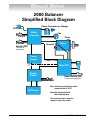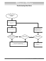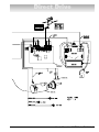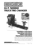
1
®
IBS 2000
Interactive Balancing System
Service Manual and
Troubleshooting Guide
with Parts Identification
P.O. Box 3002, 1601 J. P. Hennessy Drive, LaVergne, TN USA 37086 615/641-7533 800/688-6359
HENNESSY INDUSTRIES INC. Manufacturer of AMMCO®, COATS® and BADA® Automotive Service Equipment and Tools.
Manual Part No.:
9112388
Revision: 12/00 rev. 1
Direct Drive
ii • Service Manual — COATS Model IBS 2000
Contents
Introduction . . . . . . . . . . . . . . . . . . . . . . . . . . . . . . .1
Safety Notes . . . . . . . . . . . . . . . . . . . . . . . . . . . . . .1
Principal of Operation . . . . . . . . . . . . . . . . . . . . . . .1
Component Functions & Benefits . . . . . . . . . . . . . .2
2000 Balancer Simplified Block Diagram . . . . . . . .3
Servicing . . . . . . . . . . . . . . . . . . . . . . . . . . . . . . . . .4
Equipment Needed . . . . . . . . . . . . . . . . . . . . . . . . .4
Voltage & Phase Checking Procedure . . . . . . . . . . .4
Installation Instructions
Unpacking and Setup . . . . . . . . . . . . . . . . . . . . . . . .5
Hood Installation . . . . . . . . . . . . . . . . . . . . . . . . . . .5
Faceplate Assembly Installation . . . . . . . . . . . . . . . .5
Preliminary Inspection . . . . . . . . . . . . . . . . . . . . . . .5
Functional Checks
Operational Check . . . . . . . . . . . . . . . . . . . . . . . . . .6
Calibration Procedures
Balancer Calibration . . . . . . . . . . . . . . . . . . . . . .6 - 7
Plane Separation (Accuracy Check) . . . . . . . . . . . . .7
Optimizing A (Distance Guage Tape Placement) . . . .7
Arm Calibration . . . . . . . . . . . . . . . . . . . . . . . . . .7 - 8
Accuracy Problems . . . . . . . . . . . . . . . . . . . . . . . . .8
Rotation Check . . . . . . . . . . . . . . . . . . . . . . . . . . . .8
Cycle Counters . . . . . . . . . . . . . . . . . . . . . . . . . . . . .8
Total Accuracy Verification (TVA) . . . . . . . . . . . . . . .9
Error Codes
LED Error Codes . . . . . . . . . . . . . . . . . . . . . . . . . . .9
LCD Error Codes . . . . . . . . . . . . . . . . . . . . . . . .9 - 10
Troubleshooting Flow Charts
Pre-diagnostic Check . . . . . . . . . . . . . . . . . . . . . . .11
Wheel Does Not Spin . . . . . . . . . . . . . . . . . . . . . .12
Wheel Does Not Stop . . . . . . . . . . . . . . . . . . . . . .13
No Communications . . . . . . . . . . . . . . . . . . . . . . .14
Keypad Problems . . . . . . . . . . . . . . . . . . . . . . . . . .15
No LCD Display . . . . . . . . . . . . . . . . . . . . . . . . . . .16
LCD Contrast Won’t Adjust . . . . . . . . . . . . . . . . . . .17
No LCD Back-Light . . . . . . . . . . . . . . . . . . . . . . . .18
No LED Display . . . . . . . . . . . . . . . . . . . . . . . . . . .19
EE ERR . . . . . . . . . . . . . . . . . . . . . . . . . . . . . . . . .19
A & D Arm Problems . . . . . . . . . . . . . . . . . . . . . . .20
Diagnostic Procedures
Spin and Stop Diagram . . . . . . . . . .
Motor Controller Diagram . . . . . . . .
Optical Encoder Checking Procedure
Rotary Shutter Checking Procedure .
Piezo Output Test . . . . . . . . . . . . . . .
Piezo Crystal Checking Procedure . .
Balancer Display Diagnostics . . . . .
.
.
.
.
.
.
.
.
.
.
.
.
.
.
.
.
.
.
.
.
.
.
.
.
.
.
.
.
.
.
.
.
.
.
.
.
.
.
.
.
.
.
.
.
.
.
.
.
.
.
.
.
.
.
.
.
.
.
.
.
.
.
.
.
.
.
.
.
.
.
.21
.22
.23
.23
.23
.24
.24
Serial Loopback Test . . . . . . . . . . . . . . . . . . . . . . . .24
Replacement Procedures for Model
IBS 2000 Balancer . . . . . . . . . . . . . . . . . . . . . . .25-30
Display Board Assembly Replacement . . . . . . . . . .25
E-Prom Replacement . . . . . . . . . . . . . . . . . . . . . . .25
LCD Board Replacement . . . . . . . . . . . . . . . . . . . .26
Start Switch Replacement . . . . . . . . . . . . . . . . . . .26
Touch Panel Replacement . . . . . . . . . . . . . . . . . . .26
Hood Magnet Replacement . . . . . . . . . . . . . . . . . .26
Hood Switch Replacement . . . . . . . . . . . . . . . . . . .26
Safety Interlock Switch Replacement . . . . . . . . . . .26
On/Off Switch Replacement . . . . . . . . . . . . . .26 - 27
Circuit Breaker Replacement . . . . . . . . . . . . . . . . .27
Power Supply Board Replacement . . . . . . . . . . . . .27
Motor Controller Board Replacement . . . . . . . . . . .27
CPU Board Replacement . . . . . . . . . . . . . . . . . . . .27
Fan Motor Assembly Replacement . . . . . . . . . . . .28
Rotary Shutter Replacement . . . . . . . . . . . . . . . . .28
Optical Encoder Assembly Replacement . . . . . . . .28
Drive Motor Assembly Replacement . . . . . . . . .28-29
Faceplate & Shaft Assembly Replacement . . . . . . .29
Piezo Assembly Replacement . . . . . . . . . . . . . . . .29
Capacitor Assembly Replacement . . . . . . . . . . . . .30
Signal Harness Replacement . . . . . . . . . . . . . . . . .30
A/D Arm Repair and Replacement . . . . . . . . . .30-31
A/D Arm Replacement . . . . . . . . . . . . . . . . . . . . . .56
A Gear Assembly Replacement . . . . . . . . . . . . . . .57
Small D Gear Assembly Replacement . . . . . . . . . .57
Large D Gear Replacement . . . . . . . . . . . . . . . . . .58
A/D Arm Subassembly Replacement . . . . . . . . . . .58
Parts Identification . . . . . . . . . . . . . . . . . . . . . .32-35
IBS 2000 Parts Illustration . . . . . . . . . . . . . . . . .32-33
IBS 2000 Wiring Diagrams . . . . . . . . . . . . . . . .36-39
Motor and Motor Controller Checking
Procedure . . . . . . . . . . . . . . . . . . . . . . . . . . . . . . .21
Service Manual — COATS Model IBS 2000 • iii
Safety
IMPORTANT SAFETY INSTRUCTIONS
READ ALL INSTRUCTIONS
1.
Eye and face protection recommendations:
“Protective eye and face equipment is required to
be used where there is a reasonable probability of
injury that can be prevented by the use of such
equipment.” O.S.H.A. 1910.133(a) Protective goggles, safety glasses, or a face shield must be provided by the owner and worn by the operator of
the equipment. Care should be taken to see that
all eye and face safety precautions are followed by
the operator. ALWAYS WEAR SAFETY GLASSES.
Everyday glasses only have impact resistant
lenses, they are not safety glasses.
2. Do not disable hood safety interlock system, or in
any way shortcut safety controls and operations.
3. Be sure that wheels are mounted properly, the
hub nut engages the arbor for not less than four
(4) turns, and the hub nut is firmly tightened
before spinning the wheel.
4. Read and understand this manual before operating. Abuse and misuse will shorten the functional
life.
5. Be sure the balancer is properly connected to the
power supply and electrically grounded.
6. Do not operate equipment with a damaged cord
or if the equipment has been dropped or damaged
– until it has been examined by a qualified serviceman.
7.
Do not let cord hang over edge of table, bench, or
counter or come in contact with hot manifolds or
moving fan blades.
8. If an extension cord is necessary, a cord with a
current rating equal to or more than that of the
equipment should be used. Cords rated for less
current than the equipment may overheat. Care
should be taken to arrange the cord so that it will
not be tripped over or pulled.
10. Wear proper clothing. Safety toe, non-slip
footwear and protective hair covering to contain
hair is recommended. Do not wear jewelry, loose
clothing, neckties, or gloves when operating the
balancer.
11. Keep work area clean and well lighted. Cluttered
and/or dark areas invite accidents.
12. Avoid dangerous environments. Do not use power
tools or electrical equipment in damp or wet locations, or expose them to rain.
13. Avoid unintentional starting. Be sure the balancer
is turned off before servicing.
14. Disconnect the balancer before servicing.
15. Use only manufacturer’s recommended accessories. Improper accessories may result in personal injury or property damage.
16. Repair or replace any part that is damaged or worn
and that may cause unsafe balancer operation. Do
not operate damaged equipment until it has been
examined by a qualified service technician.
17. Never overload or stand on the balancer.
18. Do not allow untrained persons to operate
machinery.
19. To reduce the risk of fire, do not operate equipment in the vicinity of open containers or flammable liquids (gasoline).
20. Adequate ventilation should be provided when
working on operating internal combustion
engines.
21. Keep hair, loose clothing, fingers, and all parts of
body away from moving parts.
22. Use equipment only as described in this manual.
23. Use only manufacturer’s recommended attachments.
9. Keep guards and safety features in place and in
working order.
SAVE THESE INSTRUCTIONS
iv • Service Manual — COATS Model IBS 2000
Direct Drive
Introduction
This service manual contains the functional checks,
troubleshooting, adjustment, and part replacement
instructions for COATS® Model IBS 2000 Wheel
Balancer. Exploded views, illustrations, and an indexed
parts list facilitate parts location, ordering, and replacement. All adjustments and replacements can be rendered with mechanic's or electrician's tools.
Safety Notes
HIGH VOLTAGES, HIGH TORQUE MOTORS, and
HIGH SPEED ROTATING WHEELS are present in
COATS wheel balancers. Follow the SAFETY RULES
when servicing any balancer:
1. DISCONNECT BALANCER from power source
before starting any parts replacement or internal adjustment.
2. LOWER GUARD HOOD before starting cycle.
3. DO NOT WEAR LOOSE CLOTHING, such as neckties, while servicing the balancer.
4. LONG HAIR should be worn UP, or under a HAT.
5. WHEELS MUST BE MOUNTED PROPERLY:
• Cones must be centered in the wheel before
tightening.
• The wheel must be forced up firmly against the
faceplate.
• The hub nut must be engaged by a minimum of
four (4) full threads.
• Tighten the hub nut rotating the wheel and striking a spoke of the hub nut with the heel of the
hand.
Caution! Failure to tighten the hub nut could
result in serious injury!
Principle Of Operation
The model IBS 2000 Wheel Balancer utilizes the principle that any rigid body rotating about an axis through
the body can be balanced using weights mounted in
two planes. In this case the rigid body is an automobile
wheel and tire assembly which is mounted precisely on
center and rotated to measure the imbalance forces in
two planes. As the wheel rotates, any imbalance in the
wheel results in radial outward forces on the wheel and
the distances from the voltages produced by the piezo
sensors.
With the forces known at the planes of the piezos the
imbalance forces at the wheel planes can be calculated
by using the distance from the force transducer planes
to the wheel correction planes. These wheel imbalance
forces are displayed for the wheel planes selected during the setup procedure so the correction weights can
be added. A check spin is recommended to assure that
the wheel is in fact balanced. For the measurement to
be accurate:
1) the wheel must be mounted precisely on center
2) the wheel plane parameters must be entered accurately
3) the distance and diameter arm and the balancer
must be calibrated carefully.
The Model IBS 2000 Balancer uses several modules
to control the balancing sequence. The COATS® Direct
Drive system includes the following primary elements:
• Direct Drive Motor and Shaft Assembly
• Motor Controller Printed Circuit Board
• CPU Printed Circuit Board Assembly
• Touch Panel
• Display Printed Circuit Board
• LCD Display
The balancing operation is started by mounting the
wheel and then selecting the planes for the desired
placement of wheel weights from the touch panel. The
wheel parameters are then entered for distance, width,
and diameters appropriate for the correction planes
selected.
The measurement is started by pushing the START
switch or lowering the hood. The display PCB responds
to the START command by sending the command to
the CPU which begins the measurement cycle. The
CPU turns the SPIN SSR ON which powers the motor
in the forward direction. As soon as the motor reaches
the measurement speed the power is removed and the
wheel coasts while the signal from the piezos is being
measured. When the measurement is completed the
CPU turns on the BRAKE SSR which reverses the
motor and brings the wheel to a stop. The WEIGHT and
POSITION readings for each plane are sent from the
CPU to the Display PCB where they are displayed. The
correction planes can be changed if desired and the displays are updated automatically.
Service Manual — COATS Model IBS 2000 • 1
Direct Drive
Component
Functions & Benefits
Motor Controller
Function: Controls the AC power for the spin and brake
cycles of the motor.
Main CPU*
Function: Receives data from all input devices (piezos,
encoder, A/D pots, hoodswitch).
Benefit: Solid State Relay (SSR) replaces mechanical
contactor.
Processes the information and sends it to the appropriate PCB.
•
•
•
Eliminates contact arching, RF interference.
Eliminates mechanical problems.
Eliminates multiple wire connections.
Benefit: Separate PCB reduces board replacement
cost. Latest microprocessor design.
Also: AC power is routed through this board for the:
Phase Converter
Function: Allows three phase motor to be used on single phase power.
•
•
•
•
On/Off Switch
Cooling Fan
Power Supply PCB
Phase Converter
CAUTION
The SSR is electrically HOT any time the unit
is plugged into the wall!
Power Supply
Function: Supplies regulated voltage to operate the
electronics used on the PCB's.
+12 vdc (VDD)
-12 vdc (VEE)
+5 vdc (VBB)
Benefit: Separate PCB reduces board replacement
cost.
Also: Input voltage is AC line voltage routed through
the Motor Controller PCB
Display Board*
Function: Controls the lighting of all LED's.
Benefit: Separate PCB reduces board replacement
cost.
Also: Manual start switch connects to this PCB.
Also: Has +5 vdc (VCC) regulator
Benefit: Allows the use of three phase motors in all
balancers.
Easy to convert from one phase to three phase. Uses
same capacitor as 1050 but different connectors.
Fan
Function: Keeps the motor from overheating.
Benefit: Allows us to use direct drive motors.
Also: These fans are 220v (950/1050 has 110v).
Piezos
Function: Measures the weight imbalance in a wheel.
Benefit: Proven Technology, reliable.
Also: Same as in the 1050 but different connector and
isolated.
Encoder
Function: Aids in measuring the imbalance location, in
a wheel.
Determines rotational speed and direction.
Benefit: Proven technology.
Same as a 1050 but different connector.
Motor
Function: Used for mounting and rotating the wheel.
Power for the LCD back light and control signals come
from this PCB.
Benefit: Direct drive, no need to balance.
Has contrast pot adjustment.
Replaceable faceplate and shaft assembly.
Has +5 vcc (VCC) regulator
No belts, less noise interference.
Optional 40mm faceplate and shaft assembly.
LCD*
Function: Displays operator interactive instructions.
Benefit: Makes the unit easier to operate and calibrate.
Single PCB replacement.
Proven technology.
2 • Service Manual — COATS Model IBS 2000
*Indicates electronic components which carry a three
year warranty.
Direct Drive
2000 Balancer
Simplified Block Diagram
Phase Converter or Jumper
AC Power
Motor
Controller
On/Off
Fan
Piezo
Interlock
Switch (NO)
Encoder
Motor
Closed with
hood down
Power
Supply
A
+12
- 12
+5
Main CPU
Display
Board
D
Hood Switch (NO)
Closed with hood down
Manual Start
LCD Board
Note: Interlock switch only on models
produced after 12-22-97.
Note: NC = Normally Closed
NO = Normally Open
The normal position is when the
magnet is next to the switch.
Service Manual — COATS Model IBS 2000 • 3
Direct Drive
Servicing
Service should be performed only by a factory trained
COATS® Service Technician. The troubleshooting and
service procedures in this manual are arranged to allow
rapid and thorough service. The steps are:
• Preliminary Inspection
• Functional Checks
• Repair Of Failure
• Replacement Or Adjustment
• Functional Checks
Identification of replacement parts required can be
accomplished by using the pictorial breakdown and index
in this manual. It is important that the FUNCTIONAL
CHECKS be performed IN SEQUENCE and the PROBLEM ISOLATED. If an adjustment is made, the entire
FUNCTIONAL CHECK must be performed SUCCESSFULLY before the balancer can be considered available
for service.
Equipment Needed
1. AC / DC - Volt / Ohm meter (DVM).
2. Test Wheel - Domestic 14" x 6" steel wheel with a
center hole suitable for mounting with a back cone. A
new 195/70/14 tire properly mounted and inflated, balanced to within 0.02 ounces should be part of this wheel
assembly. The lateral run out of this wheel should be less
than 1/8". Modeling clay and 4 oz. test weight.
3. Flat and Phillips screw drivers, and dead blow hammer.
4. Tester for phone cables and jacks. (Modapt adaptor,
Contact East Part #118-785, call 1-800-225-5334 to order.)
5. Thread locking anaerobic (Loctite 242 or equivalent).
Retaining compound (Loctite 601 or equivalent).
GROUND
Y
X
6. Torque Wrench & a 5/16 X 6" hex socket for the
torque wrench.
7. Small Allen wrenches, pot adjusting tools, & a 3/8"
nut driver.
8. Chip extractor tool, Ammco part # 29977.
9. A dial indicator (runout gauge) , Ammco part # 2850,
or 29752.
10. Sockets: 3/8, 7/16, 3/4, 1/2, 9/16 inch, a speed handle, or ratchet.
11. A drill and 1/8" drill bits, pop rivet gun, and 1/8" rivets.
12. A 7/16" - 3/8" box end wrench, and cutters for banding.
Voltage & Phase Checking Procedure
1. Unplug the Balancer from the power source.
2. Perform all voltage checks shown in the appropriate
diagram and chart at the power receptacle. If one or all
voltage measurements is faulty be sure to check the status of the circuit breakers that supply the Balancer.
3. Check from one of the power terminals to the
ground terminal to verify a ground is present. The voltage
measurement should be approximately one half of the
available voltage (i.e. 220V should read 110V).
Note: If any faults are found in the above procedure, it is the responsibility of the owner.
COATS® authorized service personnel are not
responsible for wiring within the building.
4. Plug the balancer into a power source.
5. Use an Ohmmeter to check the resistance between
the frame of the balancer and the building ground. The
resistance should be less than 1 ohm. If the resistance
measurement is greater that one (1) ohm, check the
power cord plug and frame connection for proper contact.
Z
GROUND
A
GREEN
GREEN
RED
BLACK
RED
WHITE
THREE PHASE VOLTAGE REQUIREMENTS / INFORMATION
X-Y
X-Z
Y-Z
Plug
Installed
Required
Mating Outlet
208V/220V/230V
195-250
195-250
195-250
Hubbell 2421
Hubbell 2420 or
Equivalent
380V
370-420
370-420
370-420
460V
420-480
420-480
420-480
Hubbell 2431
Hubbell 2430 or
Equivalent
4 • Service Manual — COATS Model IBS 2000
BLACK
SINGLE PHASE VOLTAGE
REQUIREMENTS/ INFORMATION
A-B
Plug
Installed
Required
Mating Outlet
208V/220V/230V
195 - 250
Hubbell
5466-C
Hubbell 5462 or
Equivalent
B
Direct Drive
Installation Instructions
Unpacking and Setup
4. Slide the other nylon bushing into position from the
inside, slide on the washer and the retaining ring.
1. Remove the staples from around the bottom of the
carton, and carefully remove the box.
5. Attach the hood spring. The straight end goes at the
bottom of the machine the hook end into the hood.
2. Unstrap and remove the hood, accessory box and all
packing.
Note: The hood must be in the raised position,
to install the spring. For Safety, you should
have someone support it.
3. Inspect the unit and all accessories for damage.
Note: Report any damaged or missing parts to
the Hennessy Order Entry Department immediately. CALL 1-800-688-6359.
4. Remove the three (3) hold down brackets from the
machine & pallet. Do not discard. Retain for the customer,
he may wish to use them to bolt his unit to the floor.
5. Remove the balancer from the pallet.
Caution! This unit is very heavy and will
require assistance for lifting and moving. DO
NOT DROP! DO NOT LIFT BY THE MOTOR
SHAFT!
Note: If there is a bolt on the back of the hood
support bracket, near the bottom right side of
the accessory column, REMOVE IT. It will interfere with the hood installation.
6. Remove the Allen head bolt at the bottom of the pod
tube, and retain for later use.
7. Loosen the four (4) bolts on the tube brackets, and
slide the tube into position with the locating ring.
8. Install the Allen head bolt.
Caution! Be careful not to damage the wire
harness.
9. “Snug” the bolts on the tube brackets, but do not
overtighten. The Pod should swing with some resistance,
but not loosely.
10. Push the harness into the pod tube, and install the
plastic cover.
11. Check the power plug with the phase of the
machine on the serial tag. Make sure the plug matches
the customers outlet.
Hood Installation
1. Install the hood magnets (two sets, for hood switch
and interlock switch to the holes on the hood cam. The
nylon washer goes between the magnets and the cam.
Do not over tighten, or the magnets will break.
2. Slide one of the nylon bushings onto the hood bar,
flange to the cam.
3. Lift the hood up and slide the bar into the machine,
you may need assistance. Let it rest on the hood stop.
Faceplate Assembly Installation
1. Remove the hub nut and cones from the threaded
shaft. Store on the accessory pegs.
2. Clean the contacting surfaces of both the motor shaft
and faceplate assembly with a soft cloth. Note the witness marks on both, these should be aligned before
installing.
3. Slide the 6 inch socket head bolt (included in the parts
bag) and the (5/16 X 6") Allen wrench extension into the
faceplate assembly. Hand tighten.
4. Attach the torque wrench. Hold the faceplate with
one hand to keep from turning. Tighten to 20 ft/lb.
Caution! DO NOT OVER TIGHTEN. Over tightening will result in damage to the motor shaft.
5. Dial indicate the faceplate and shaft assembly there
should be not more than .002-inch on the faceplate and
not more than .001 runout on the shaft. If so refer to
Faceplate Assembly Replacement procedures.
Preliminary Inspection
1. The floor should be a solid, flat surface that does not
allow the balancer legs to set into a recess in the floor or
sink into the floor itself.
2. The balancer should sit on all three (3) legs. Make
sure the legs have not filled with dirt, wheel weights, or
any foreign matter that may prevent a leg from making
contact with the floor.
3. Inspect all cones, hub nut, pressure cup, motor shaft,
faceplate, and shaft assembly for damage. Missing parts
or accessories should be reported immediately to
Hennessy Order Entry Department at 1-800-688-6359.
4. Check the power supply to the balancer. Refer to the
VOLTAGE CHECKING PROCEDURE.
5. Check the operation of the cooling fan on the drive
motor. The fan should run as soon as the balancer is
turned on. If not, check the breaker on the Accessory
Column of the balancer. If it has tripped, reset it. If it will
not reset refer to the PRECHECK procedure.
6. Check the rotation of the motor. Press START, does
the motor spin clockwise? If not, for a 3ph Balancer switch any two of the hot leads on the plug.
Service Manual — COATS Model IBS 2000 • 5
Direct Drive
Functional Checks
Operational Check
11. The balancer should now have weight values and
position lights displayed.
1. Turn the power switch ON. The display should read
as follows:
12. Rotate the wheel so the top and bottom position
LED's for the outside (right) plane are flashing.
LCD:
13. Note the position of the 4 oz. weight and the
weight readings for both planes.
Grams/Ounces - Defaults to last selection.
Mode - Round off ON
Hood Start - Hood Start ON
A, W, D - 0.00
PRESS ANY KEY TO CONTINUE
If the LCD Does Not Light, see flow chart for No LCD
Display.
LED: Weight Displays - 0.00
Mode - Dynamic
Operator - A
If the LED's do not light, see flow chart for No LED
Display.
2. Mount your test wheel (described in EQUIPMENT
NEEDED) on the balancer.
3. Enter the wheel parameter data using the automatic A/D arm.
Note: If you do not get proper wheel parameters from the A/D Arm, check the A&D
potentiometers found in the CALIBRATION
MENU, follow the procedures for Arm calibration. If the A/D arm has failed, you may
manually enter the data. If the Keypad does
not work, see TOUCH PANEL PROBLEMS.
4. If the balancer is in round off mode, go to the SET
UP menu, select NON-ROUND OFF and press enter.
5. Go to the SET UP menu, select the desired weight
mode (this procedure may be performed in either
mode) GRAM or OUNCE and press enter.
6. Install a 4 oz./100 gram weight on the outer rim of
the test wheel.
7. Choose the DYNAMIC balancing mode.
8. Lower the guard hood. (if HOOD START is on, the
balancer will automatically cycle at this time, if not see
step 9).
9. Push the START button. The machine should now
cycle. If the machine does not cycle, see BALANCER
DOES NOT SPIN.
10. The balancer should come up to speed, coast for
several revolutions, and then brake to a stop. If the
machine fails to brake and continues to coast, see BALANCER DOES NOT STOP.
6 • Service Manual — COATS Model IBS 2000
14. Now rotate the wheel so the center LED for the
outer (right) plane is flashing. The 4 oz. weight should
now be at (or near) the 6:00 position.
15. Perform five (5) cycles and note the positions and
weight readings after each spin. The weight readings
should repeat within .2 oz. and the position within + 1/2
inch. If they do not, see ACCURACY PROBLEMS.
Note: If the customer has problems with a
specific wheel assembly only, make sure there
is no water or debris inside the assembly.
Calibration Procedures
Balancer Calibration
1. Turn the power switch ON.
2. Mount your test wheel to the machine.
3. Enter the wheel parameters using the A/D arm and
the rim calipers.
4. If the machine is in ROUND OFF mode go to the
SET UP menu and select NON-ROUND OFF.
5. If the machine is not in OUNCE mode go to the
SET UP menu and select OUNCES.
Note: This procedure can be performed
using GRAMS or OUNCES. If using GRAMS,
refer to a conversion chart for weight conversions.
6. Go to the MAIN menu and select CALIBRATE BALANCER to enter the calibration mode. The status bar
should now read CAL 0. Follow the instructions on the
display.
7. Push the START button, or lower the hood. The
machine should now cycle. This cycle is referred to as
the zero spin cycle.
8. The balancer should come up to speed, coast for
several revolutions, and then brake to a stop.
9. The status bar should now read CAL 1. Follow the
instructions on the display.
Direct Drive
10. Position the wheel so the display for the center
position LED on the outside (right) plane is flashing.
11. Place a 4 oz. weight at the 12 o'clock position on
the outside (right) of the wheel.
Note: If a weight is already in this position,
place the 4 oz. weight as close to the indicated location as possible. Rotate it to the
12 o'clock position, and then press the Star
(*) key.
12. Push the START button, or lower the hood. The
balancer should now cycle and come to a stop.
6. If the above results are not achieved check the A,
W, and, D dimensions. The ARM must be OPTIMIZED.
Perform the ARM CALIBRATION.
7. If the above results are still not achieved, check the
placement of the distance tape, see OPTIMIZING
A(Distance Tape Placement).
8. If specified results are not achieved see ACCURACY PROBLEMS.
Optimizing
Placement)
A
(Distance
Gauge
Tape
Note: Perform this procedure if the PLANE
SEPARATION (Accuracy Check) fails.
13. The outer (right) weight display should read 4.00
± .02 oz. and the center position LED for the outside
(right) plane should be flashing when the weight is at
bottom dead center. The display will now read CALIBRATION COMPLETE! PRESS ANY KEY TO CONTINUE.
1. Place a 4oz. wt. on the inside of the wheel, try
entering an A dimension .1 higher than the one used
originally. Spin the wheel. If the plane separation gets
worse, try using an A dimension .1 lower than the one
used originally.
14. Perform PLANE SEPARATION, if specified results
are achieved calibration is complete. If specified results
are not achieved , OPTIMIZE THE A.
2. If the plane separation gets better, keep increasing
or decreasing the A dimension until an acceptable
value is achieved.
15. Make sure to write down the new A value to use
in the ARM CALIBRATION procedure. Center position
LED for the outside (right) plane should be flashing
when the weight is at bottom dead center. The display
will now read CALIBRATION COMPLETE! PRESS ANY
KEY TO CONTINUE.
3. Calibrate the machine and perform the PLANE
SEPARATION CHECK. Repeat this procedure until the
outer plane weight reading is at a minimum.
Plane Separation (Accuracy Check)
1. Remove the 4 oz. weight from the wheel.
2. Use putty to fine balance the test wheel to obtain
0.00 (+0.02) weight readings on both planes. If unable
to balance to zero See REPEATABILITY PROBLEMS.
Note: If the customer balances mostly larger
wheels you may use a larger wheel for calibration.
3. Place a 4 oz. weight on the outside of the wheel.
4. Once the A is Optimized and the distance tape
moved, you must perform ARM CALIBRATION and
BALANCER CALIBRATION with the new A value. Also
recheck the PLANE SEPARATION.
5. Move the distance tape to this position to allow for
proper A dimension entry.
Arm Calibration
1. Go to the menu and select CALIBRATION, select
CALIBRATE ARM. Follow the instructions on the display. The A & D pot readings are displayed on the LCD
display. With the arm in the HOME position, the readings should be within the tolerance brackets.
4. Press start, or lower the guard hood. The readings
for this cycle should be as follows:
Inner (Left) Plane = 0.00 ± 0.15 oz.
Outer (Right) Plane = 4.00 ± 0.15 oz.
Outer Position flashing = 4oz. at bottom dead center
± 1/2inch
5. Move the 4 oz. weight directly across to the inside
plane. Press start, the reading should be as follows:
Inner (Left) Plane = 4.00 ± 0.15 oz.
Outer (Right) Plane = 0.00 ± 0.15 oz.
Inner Position flashing = 4oz. at bottom dead center
± 1/2 inch
If not, the potentiometers should be adjusted. Refer
to the A & D Arm Repair Procedures.
2. Place the arm in the home position (see decal on
the motor). Follow the instructions on the display
screen.
3. The A value is obtained by moving the distance arm
out to the rim, and manually entering the new A value
obtained from the PLANE SEPARATION and A OPTIMIZATION.
Service Manual — COATS Model IBS 2000 • 7
Direct Drive
4. Enter the D value from the tire. It should be within
.10 of the reading from the automatic arm, if not the D
pot should be adjusted (refer to A & D ARM REPAIR
PROCEDURES). Manually enter the value.
5. After both values have been manually entered,
move the distance arm to the rim and hold it in position
while pressing CONTINUE.
6. Rotate the arm out and around to a second position on the rim. Holding the tip against the rim flange,
press CONTINUE.
Arm Calibration is now complete. When the arm is
returned to the HOME position, the balancer will return
normal operating mode.
7. To verify the calibration, pull the arm out and hold
the tip against the rim flange. The A & D readings automatically displayed should be +0.20 of the values
entered during calibration. If not, see OPTIMIZING A
(DISTANCE TAPE PLACEMENT) and A & D Arm
Problems.
Rotation Check
Note: This procedure must be performed
with a “Hub Centric” wheel. It should be
performed as part of every routine calibration procedure.
1. Remove the 4oz. weight from the inner rim and
perform a fine balance to obtain 0.00 (+.02) weight
readings on inner and outer plane.
2. Position valve stem at 6 o'clock. Loosen hub nut
just enough to allow the wheel to move. While holding
the faceplate so it cannot turn, rotate the wheel 90
degrees relative to the faceplate. Tighten hub nut.
3. Press START. Weight readings should be 0.32 oz.
or less.
4. Repeat steps 2 & 3. At 180 and 270 degrees
weight readings should be .32 oz. or less.
5. If the specified results are not achieved see ROTATIONAL PROBLEMS.
Accuracy Problems
Cycle Counters
Mounting Errors - Causes comebacks but not
detectable with the balance. Check the runout of the
shaft, faceplate and cones.
These counters can be accessed through the DIAGNOSTICS menu. Each cycle counter is different. They
may be beneficial to the shop owner as a management
tool.
Wheel Slipping During Rotation - Causes repeated
spins or inability to balance the wheel. Check by marking the wheel & faceplate, correct by tightening the
hub nut or using front cone.
Improper Wheel Parameters - or Inaccurate Wheel
parameters such as approximate ALU modes. Causes
inability to balance the wheel. Enter more accurate
parameters and or mount hidden weight closer to the
PRESET position for hidden weights.
Uncalibrated Data Entry Arm - Causes repeated
spins to balance. Perform Plane Separation (Accuracy
Check)
Uncalibrated Balancer - Causes repeated spins to
balance. Perform a PLANE Separation (Accuracy
Check).
Something Touching The Motor Or Distance Arm Causes inability to calibrate the balancer or achieve
acceptable PLANE SEPARATION. Check for anything
touching the motor.
Rotary Shutter Slipping - Causes weight position to
change, repeat spins, or inability to balance. Perform
Rotary Shutter Checking Procedure.
8 • Service Manual — COATS Model IBS 2000
User Counter - can be reset at any time by anyone to
determine number of spins per day, hour, or per user.
Calibration Counter - this automatically resets each
time the balancer is calibrated. It can be a useful tool to
see how often the balancer is being calibrated. As a
routine this should be checked when a customer complains of weight chasing or calibration problems. A low
count could indicate the customer is calibrating too
often or calibrating incorrectly.
Total Counts - counts the total number of cycles on
the balancer. It is not resetable, however if the CPU
board is ever replaced it will reset.
Direct Drive
Total Accuracy Verification (TVA)
Total Accuracy Verification or TAV means that when
the balancer shows zeros in the weight display after
balancing the wheel it is truly balanced. The model IBS
2000 includes software that will allow the user to check
the accuracy of his machine periodically. The procedure
is detailed below.
1. Go to the Main Menu and select SETUP. Press
enter.
2. Arrow through the selections to TAV. Press enter.
3. The menu will now display several “preset” selections to choose from, or the customer may wish to
SPECIFY. Press Enter.
4. If SPECIFY is selected, the menu will prompt to
enter the number of cycles desired. Enter the number
and press enter.
Note: If the preset number is less than 250
the first message will appear at the preset
number. Subsequent messages will also
appear at that interval.
Example A:
Cycles Since
Last Calibration
Message
10
The preset number of TAV cycles has
been reached, do you wish to perform TAV?
20
The preset number of TAV cycles has
been exceeded, do you wish to perform TAV?
Error Codes
LED Error Codes
When the balancer is powered up, several communication checks are made. If the data is incorrect, or not
received the balancer generates the following error
codes in the weight amount LED's on the display.
LCD ERR - unable to communicate with LCD:
Displayed when the Display board is unable to communicate with LCD board. This halts the program. Check
the LCD ribbon, and all connections. Most likely the ribbon is not installed properly, backwards or on wrong
pins. Possibly the LCD board.
EE ERR - unable to communicate with the EE PROM:
Displayed when the EE PROM (on the display board)
cannot read or write. It cannot restore display settings,
this is a combination of messages 7 and 8. Replace the
display board.
LCD Error Codes
The following list of error codes, are Built In Safety
Features. When the balancer is cycled several operating parameters are checked. If one of these parameters
is not within tolerance, the machine will generate an
error message displayed on the LCD readout. An explanation of these messages and troubleshooting procedure is listed below:
#1 - The Motor Speed Was Excessive: Displayed
when the motor exceeds normal operating speed at
any time during the cycle. Check the SSR (solid state
relay).
5. If NO is selected, the balancer will resume normal
operation.
#2 - Time To Reach Minimum Operating Speed Too
Long: Displayed when time to reach the minimum
operating speed is greater than 20 seconds. Check
cables, SSR, or CPU.
Note: If the preset number is equal to or
greater than 250, the first message will
appear at the preset number and again
every 250 cycles.
#3 - Time To Reach Maximum Operating Speed Too
Long: Displayed when time to reach maximum operating speed exceeds 14 seconds. Check cables, SSR, or
CPU.
Example B:
Cycles Since
Last Calibration
Message
500
The preset number of TAV cycles has
been reached, do you wish to perform TAV?
750
The preset number of TAV cycles has
been exceeded, do you wish to perform TAV?
7. If YES is selected, the balancer will automatically
enter the calibration mode. Follow the instructions on
the display.
#4 - The Measurement Time Was Too Long: Displayed
after the motor gets up to speed but the time to set
GAIN (an internal measurement) is too long. Check
cables, optical encoder, or CPU.
#5 - The Measurement Time Was Too Long: Displayed
when the time to FILTER (an internal process) is too
long. Check cables, optical encoder, or CPU.
#6 - Not Used.
#7 - Internal Error Code: Displayed when a write error
on the EE PROM (of the CPU board) has occurred.
Calibration information, counters, etc. Replace CPU
board.
Service Manual — COATS Model IBS 2000 • 9
Direct Drive
#8 - Internal Error Code: Displayed at power up when
the data on the EE PROM is different than when the
unit was turned off. Recalibrate the Balancer and the
A/D Arm. If this message continues replace the CPU
board.
#9 - An Invalid Model Selection Has Been Made:
Displayed when the dipswitches on the CPU board are
not set correctly, or the connections are bad. Check the
dipswitch settings (they should all be in the ON position) and reset if necessary. If this does not correct the
problem, replace the CPU.
on the motor shaft. Recheck the hubnut or refer to
“Faceplate Assembly Installation” on pg. 5. Press
CONTINUE to proceed.
#21 - The Wheel Is Turning Too Fast For A
Measurement To Be Made: The motor speed is greater
than the maximum operating speed.
#22 - The Wheel Turned In Reverse After The Motor
Was Started: Displayed when something interferes
with the rotation of the wheel after start up (someone
holding the wheel). Press CONTINUE to proceed.
Check cables or SSR. Press CONTINUE to proceed.
#10 - The Automatic Arm Is Not Present: Displayed
during Arm Calibration when the CPU cannot detect
the arm. Check the arm cable/PCB connections, or the
CPU connector.
#23 - The Wheel Turned Too Slow: Displayed under
similar conditions as #22 . Check cables or SSR. Press
CONTINUE to proceed.
#11 - The A & D Pots Are Not Properly Adjusted:
Displayed during Arm Calibration if the pots were not
properly adjusted. Press CONTINUE to readjust, or
CANCEL to quit.
#24 - The Motor Accelerated Forward During
Breaking: Displayed when there is a phase problem
with the SSR, very rare. Check loose shutter wheel or
loose faceplate. Check encoder cable, AC power,
motor, and SSR. Press CONTINUE to proceed.
#12 - The A Pot Is Not Properly Adjusted: Displayed
when the A pot is not reading correctly. Same as #11
except for the A pot only. Press CONTINUE to readjust,
or CANCEL to quit.
#25 - The Time Required To Stop The Motor Was Too
Long: Displayed if a phase is lost on the SSR. Check AC
power, cables, and SSR. Press CONTINUE to proceed.
#13 - The D Pot Is Not Properly Adjusted: Displayed
when the D pot is not reading correctly, Same as #12
except for the D pot only. Press CONTINUE to readjust,
or CANCEL to quit.
#14 - The Hood Was Raised During The Measurement
Cycle: Displayed if the hood is raised during the cycle.
Lower the hood and respin.
#15 - The Motor Ran In Reverse At Start Up: Displayed
when the motor accelerated in reverse at start up.
Check phase, AC power, or MC (motor controller).
#16 - The Arm Was Not In The Correct Position:
Displayed during Arm Calibration if you get out of
sequence. Press CONTINUE to repeat or CANCEL to
quit.
#17 - No Encoder Pulses At Start Up: Displayed when
no encoder is detected at start up. Check cable, AC
power and motor. Refer to “Wheel Does Not Spin”
flow chart.
#18 - No Phase A Encoder Pulse At Start Up: Same as
#17, but for Phase A only. See “Wheel Does Not Spin”
flow chart.
#19 - No Phase B Encoder Pulse At Start Up: Same as
#17, but for Phase B only. See “Wheel Does Not Spin”
flow chart.
#20 - The Hub Nut Is Loose Or There Is No Wheel
Mounted: Displayed when the hub nut is not tight and
the wheel slips, or the faceplate assembly is not tight
10 • Service Manual — COATS Model IBS 2000
Direct Drive
Troubleshooting Flow Charts
Pre-diagnostic
Pre-diagnostic
Check
check
M a ke s u r e t h e u n i t i s
plugged in.
Tu r n t h e p ow e r o f f,
unplug the unit, and
c o n n e c t t h e fa n .
Tu r n t h e p o w e r o n .
No
Does the
b a l a n c e r d i s p l ay
appear?
Ye s
No
D o e s t h e fa n
turn on?
Ye s
C o n t i n u e t r o u bl e s h o o t i n g .
S e e i n d u v i d u a l t r o u bl e s h o o t i n g c h a r t .
No
I s t h e fa n
connected?
Ye s
Tr o u b l e s h o o t t h e AC
p o w e r.
Service Manual — COATS Model IBS 2000 • 11
Direct Drive
Wheel Does Not
Wheel does
Spinnot spin
Perform prediagnostic check
(balancer must be
displaying
merchandising
message to proceed).
Enter the
A/W/D
No
Replace the motor
controller.
Check set-up to
verify auto-spin is
on. Attempt to spin
the wheel.
Did you enter
wheel
parameters?
Yes
Yes
Does an error
message appear?
Yes
Unplug
P3 on motor
controller. Check for
+5v on pin 3 of
CPU?
Cross reference
error message to
table and
troubleshoot from
the given location.
No
No
Does the wheel
start to spin?
No
Check control
cable from main
CPU to MC Board.
Is it Plugged in?
Check for +5v on
pin 1 of P12
(control) on the
main CPU
Yes
No
Yes
No
Plug it in.
Does it
complete the
spin?
Yes
Check Interlock
switch cable on
P7of MC board. Is
It plugged in?
Check/Replace control
cable.
Replace motor
controller.
Yes
Replace
Interlock
switch.
Troubleshooting
Complete, calibrate.
Troubleshoot AC.
No
Yes
No
Yes
Do you have
+5v on pin 3 P10
(power) on The
main CPU?
No
No
Disconnect Interlock
switch from P7 on the MC
board. Check continuity
(with the hood down)
between pins 1&2. Do
you have continuity?
Is the voltage
correct on T1of
the MC board?
12 • Service Manual — COATS Model IBS 2000
Yes
Does voltage
on P12-1 drop to
+.45v when spin is
pressed?
No
Replace the CPU.
Yes
Replace motor
controller.
Direct Drive
Wheel Does Not
Wheel does
Stopnot stop.
Perfor m prediagnostic check
(balancer must be
displaying
merchandising
message to proceed).
Does an error
message appear?
No
Ye s
Does wheel
attempt to stop?
Replace the motor
controller.
Ye s
Ye s
Cross reference
error message to
table and
troubleshoot from
the given location.
Unplug
P3 on motor
controller. Check for
+5v on pin 3
CPU?
No
No
Do
readings appear
on display after
wheel has
stop?
Ye s
Check for +5v
on P12 (control) pin
6 of the CPU?
No
Do you
have +5v on
P12 pin 3 of
CPU?
No
Ye s
Ye s
Check/Replace control cable.
Replace motor controller.
No
Does voltage
on P12-6 drop to
+.45v during stop
cycle?
Replace CPU
No
Replace the CPU.
No
Troubleshoot AC.
Ye s
Replace motor
controller.
Ye s
Is the voltage
correct on T1?
Service Manual — COATS Model IBS 2000 • 13
Direct Drive
No
No
Communications
Communications
Preform prediagnostic check
(balancer must be
displaying
merchandising
message to proceed).
Did you replace a
software chip?
No
Check serial cable.
Is it plugged in?
*Note: to perform loop-back
test refer to that section in
this manual
Yes
Check for bent
prongs, or repostion
the chip. Did this
correct the problem?
No
Plug cable in and
recheck.
No
Replace
display board.
No
Replace CPU board.
Yes
No
Yes
Perform loop-back
test* with new cable?
Does unit work?
Yes
Replace
communication
cable.
Yes
Troubleshooting
complete.
14 • Service Manual — COATS Model IBS 2000
Yes
Yes
Direct Drive
Keypad Problems.
Problems
Keypad
Perfor m prediagnostic check
(balancer must be
displaying
merchandising
message to proceed).
Ye s
Cycle the power
again. Does this
correct the problem?
Ye s
Wa s key p a d l o cke d
up at power up?
No
Perfor m keypad test
f r o m m a i n m e nu
Diagnostic. The
balancer must be
displaying infor mation
to proceed. Does this
indicate a problem?
Ye s
No
Replace Keypad
No
Check keypad
connections.
Does this correct the
problemt?
Ye s
Troubleshooting
complete.
NOTE: When a key is shor ted or locked down at power up,
1. the LCD may be lighted but blank.
2. the "Press Any Key to Continue" message may be
displayed.
3. the LCD may be in another mode such as:
ADJUST LCD CONTRAST
BALANCER DISPLAY DIAGNOSTICS
Service Manual — COATS Model IBS 2000 • 15
Direct Drive
No
LCD Display
Display
No LCD
Perfor m prediagnostic check
(balancer must be
displaying
merchandising
message to proceed).
Adjust contrast
Yes
Is LCD display
blank?
Yes
No
Adjust contrast. Turn
Power Off. Hold down
the first rim key while
tur ning the power
back on. or use the
potentiometer on the
top of the display
board.
Yes
Are LED's
displaying the
merchandise
message?
No
No
No
Check LCD cable
& LCD.
Yes
Is display
completely dark?.
Is display
illedgible?
Yes
Replace display board
Does display
s h ow L C D E R R ?
No
Adjust contrast.
Yes
Does it beep
5 seconds after
power on?
No
Troubleshoot power
supply and AC
voltages.
No
Are all AC & DC
voltages correct
16 • Service Manual — COATS Model IBS 2000
Yes
S e e K E Y PA D
problems. Does
this correct the
problem?
No
Replace the
display board.
Direct Drive
LCD Contrast
LCD Won’t
Adjust
Contrast won't adjust
Perfor m prediagnostic check
(balancer must be
displaying
merchandising
message to proceed).
Replace CPU
Ye s
Check -12 vdc on
power suppy.
No
Disconnect
P10 (power) on the
CPU. Check -12v
again?
No
Refer to DC wiring
diagram #112368.
No
Use set-up menu,
adjust contrast.*
No
Replace display board
Ye s
Is hardware
adjustment
(potentiometer)
present on display
board?
Ye s
Adjust potentiometer
on back of display
board. Does this
correct the problem?
No
Replace
display
board
Ye s
Ye s
Troubleshooting complete.
*NOTE: Tur n the power off. While
holding down the first (from the left) rim
weight locator key, Tur n the power back
on. This will get you into the contrast
adjustment mode. Adjust as necessar y
and Save setting.
Service Manual — COATS Model IBS 2000 • 17
Direct Drive
No
LCD Back-Light
No LCD
Back-light
Preform prediagnostic check
(balancer must be
displaying
merchandising
message to proceed).
Is LED backlight
cable plugged in?
No
Plug cable in and
recheck.
No
Replace display
board.
Yes
Check for
4 vdc P4-2 of the
display board?
Yes
Replace LCD
module.
Yes
Troubleshooting complete.
18 • Service Manual — COATS Model IBS 2000
Direct Drive
No
Display
No LED
LED Display
EE ERR
EE
ERR
Perform prediagnostic check
(balancer must be
displaying
merchandising
message to proceed).
Does LCD
display work?
Do pre-diagnostic
c h e ck
(balancer must be
displaying
merchandising
message to proceed).
No
Troubleshoot LCD.
Turn unit off then on.
Does EE ERR go
away.
No
Replace display board.
Yes
Yes
Adjust LED
brightness?
No
Replace display
board.
Troubleshooting complete.
Yes
Troubleshooting complete.
Service Manual — COATS Model IBS 2000 • 19
Direct Drive
A & D Arm
Problems
Keypad
A/D
ARM Problems.
PROBLEMS
See KEYPAD flow
chart.
Perform prediagnostic check.
No
Check
Potentiometer
adjustments. See
ARM
CALIBRATION.
Are the
potentiometer
readings within
tolerance?
Is the ar m in HOME
position?
Yes
Adjust the
potentiometers. Are
the readings stable?
No
Yes
Check Cable
connections at CPU
board and Ar m.
No
No
Return the arm to
HOME. Is the W
now flashing?
Use VOM to check supply
voltage on the A & D
potentiometers. Between
pins 1&3 for D, and 4&6
for A. Is voltage stable?
Yes
No
Check
connections or
replace the
potentiometers.
Yes
Use VOM to check
voltages on the
potentiometers
between 2&3 for D
and 5&6 for A. Are the
readings stable?
Yes
Yes
Replace the cable.
Yes
Troubleshooting
complete.
Return to
operation.
Yes
Use VOM to check
voltage on P7 of
CPU board;
between pins 1&2
and 4&5. Are the
readings stable?
No
Troubleshooting
comptete. Calibrate
the arm. Calibrate the
balancer.
20 • Service Manual — COATS Model IBS 2000
Replace CPU
board.
Troubleshooting
complete.
Calibrate the Arm,
Calibrate the
balancer.
Direct Drive
Diagnostic Procedures
Motor and Motor Controller Checking
Procedure
To verify the operation of the motor and motor controller the SSR's (Solid State Relays) must be activated.
To do this it is necessary to simulate the signal produced by the CPU.
Note: Use of an in-line adapter is recommended for this procedure, like the one from
Contact East, (part #118-785 Modapt
Modular Adapter). For ordering information
call, 1-800-225-5334.
1. Check for 5 vdc on the CPU location P12/CONTROL pins 1, 3 and 6 (Tabs 2, 4 and 7 of the Modapt
Adapter). If Voltage is not present refer to the DC voltage checks.
2. To activate the spin, connect a jumper to circuit
ground and touch pin 1 of P12/CONTROL (Tab 2 of the
Modapt adapter). The motor should run clockwise. If
the motor fails to respond refer to the WHEEL DOES
NOT SPIN trouble shooting guide.
CAUTION! DO NOT perform this procedure
for more than Two (2) seconds.
Caution! If the spin and brake are activated
at the same time, the motor controller will
be destroyed!
3. To activate the brake connect a jumper to circuit
ground and touch pin 6 of P12/CONTORL (Tab 7 of the
Modapt Adapter) The motor should spin counter clockwise. If the motor fails to respond, refer to the WHEEL
DOES NOT STOP trouble shooting guide.
Note: Use CIRCUIT GROUND for checking
voltages. Refer to the wiring diagram
#112368, in the back of this book.
Caution! DO NOT perform this procedure for
more than Two (2) seconds.
3-13-98
Service Manual — COATS Model IBS 2000 • 21
Direct Drive
Motor Controller Diagram
22 • Service Manual — COATS Model IBS 2000
Direct Drive
Optical Encoder Checking Procedure
Piezo Output Test
This procedure allows you to check the optical
encoder to determine if it is operating properly. A
defective encoder can result in spin or braking problems.
This procedure allows you to look at the piezo output
readings to diagnose a problem with any of the piezos.
Piezo problems can cause incorrect weight readings
resulting in weight chasing problems.
1. When reading the voltages on the white and green
wires, turn the faceplate slowly by hand. The low voltage must be less than .7VDC. The high voltages must
be greater than 4.0VDC.
1. Go to the main menu and select DIAGNOSTICS,
press enter.
2. Voltage readings are taken with all optical encoder
wires connected.
Lead Color
Voltage
GREEN to PURPLE - 2.4 ± .5VDC
YELLOW to PURPLE - Less than .7VDC; greater
than 4VDC
BLUE to PURPLE - Less than .7VDC; greater
than 4VDC
Refer to the wiring diagram.
2. Select PIEZO OUTPUTS, press enter. The screen
will now display the piezo readings. Each piezo is measured individually, L = left, RF = right front, and RR =
right rear.
3. The amplitude reading is the one we will refer to for
diagnosis. Only use the first number to the right of the
decimal, disregard all others.
4. Using a balanced wheel, put a 4oz. weight on the
outside, spin the wheel. The left reading should be
approximately 25% less than the right front and right
rear readings. Both right readings should be approximately the same.
Rotary Shutter Checking Procedure
This procedure will detect movement of the rotary
shutter during a spin cycle. Slippage of the shutter
wheel can cause the weight location to change resulting in weight chasing, or spin error messages as a
result of an incorrect encoder count.
1. Mount a balanced wheel on the machine. Add a 4
oz. weight to the outside plane and spin the wheel.
2. Rotate the wheel so the center position LED light
is on. Mark the tire or wheel with respect to the witness mark on the motor.
3. Spin the wheel again, then rotate the wheel so the
center position light comes on again. Note the position
of the mark you made on the tire or wheel. You may
need to make several spins.
5. Spin the wheel for several revolutions and note the
readings in between each spin. Look for consistency in
the readings.
6. Now remove the 4 oz. wt., with a balanced wheel
add a 1oz. weight to the outside of the wheel. Spin the
wheel and check the piezo outputs. Add a 2 oz. weight
where the 1 oz. was, and spin the wheel. The readings
should double. Add a 3 oz. weight and the readings
should triple.
Note: If the readings fluctuate a great deal
check the piezo connector and refer to the
“Piezo Replacement Procedures”.
4. If the position changes, the rotary shutter has
slipped. Refer to the Rotary Shutter Replacement procedure to tighten and recheck.
Note: This procedure can be used to check
for loose faceplate, however mark the faceplate instead of the wheel.
Service Manual — COATS Model IBS 2000 • 23
Direct Drive
Balancer Display Diagnostics
Piezo Crystal Checking Procedure
This procedure details how to check for an “upside
down” piezo assembly (the crystal has been assembled upside down inside the piezo assembly). This can
result in various problems; primarily high weight readings, or the position may read 180 degrees out. The
piezos may be checked in or out of the balancer. The
procedure below details checking them in the balancer.
1. Using a Digital Volt Meter select the DC setting.
2. Connect the red (positive) lead to the piezo tap.
3. Connect the black (negative) lead to ground (the
bottom of the piezo assembly).
4. The meter may indicate a fluctuating or negative
reading, ignore the reading at this time.
5. Apply firm downward pressure to the front of the
motor (if out of the balancer apply pressure directly to
the piezo) and note the signal.
6. If the piezo is good, the signal should read positive
(+) at the instant pressure is applied for *right piezos.
7. If the piezo assembly is “upside down” the signal
will read negative (-) at the instant pressure is applied
for *right piezos.
*Note: When checking the left piezo the
readings in step 6 and 7 will be opposite.
This is a diagnostic menu that should only be
accessed by authorized Hennessy service personnel. It
allows you to perform tests on the components within
the POD. To access this menu you press the PLANE 2
key on the WEIGHT LOCATOR display and turn the
power on simultaneously. You may use the RS232 cable
or a spare “test” cable. The menu will display several
tests. Each test will display step by step instructions.
Tests on this Menu Include:
•
•
•
•
KEY PAD TEST
LCD TEST
LED TEST
RAM TEST
Note: This is not the same RAM test on the
main diagnostic menu. This RAM test is for
the LCD board.
• SOFTWARE REVISION
• SERIAL LOOPBACK TEST
Serial Loopback Test
This is a Display Board software communication test.
It checks the transmitted and received data. Follow the
instructions on the screen.
1. Connect a cable between the CPU1 (P3) and TEST
(P2) connections on the top of the display board. Refer
to the wiring diagram #112368 on Press CONTINUE.
2. The screen will not display the Transmit data and
the Received data.
3. You will then receive a PASSED or FAILED message.
Note: If the test FAILED, check and replace
the cable or the display board. If the test
PASSED, but you still get a communication
error, check the CPU board RS232 cable or
the CPU board itself.
24 • Service Manual — COATS Model IBS 2000
Direct Drive
Parts Replacement Procedures for
Model IBS 2000 Balancer
The procedures in this section will aid in replacing
major subassemblies of the IBS 2000 balancer.
Do not disassemble, adjust or replace any part before
performing the PRELIMINARY INSPECTION and
FUNCTIONAL CHECK PROCEDURES. These procedures, along with the troubleshooting flow charts, will
isolate the necessary adjustment or replacement.
Perform checks in the order listed and exactly as specified.
Refer to the exploded parts view, parts list and wiring
diagrams in this manual for parts identification.
Standard commercial fittings and fasteners are used
throughout and should be obtained locally.
Check all interconnecting wiring and connectors
when an electrical malfunction is indicated. Check all
fittings and fasteners when a mechanical malfunction is
indicated.
New Repair Procedure - The model IBS 2000 is different from other Coats balancers in that it contains
five (5) separate boards which can be replaced individually. Always refer to the Trouble Shooting section for
diagnostic instructions to isolate the defective assembly.
Note: ALWAYS REFER TO THE WIRING DIAGRAM (#112368) in the back of this book for
the following procedures.
Display Board Assembly Replacement
1. Unplug the balancer.
2. Remove the four (4) nuts on the back of the pod.
3. Disconnect the power supply wire from P1.
4. Disconnect the RS232 connector from P3.
5. Disconnect the (red) start switch wire from P8.
6. Disconnect the (grey) LCD backlight wire from P4.
7. Disconnect LCD ribbon from P5.
8. Remove the four (4) screws from the display board.
9. Carefully raise the board, and disconnect the keypad ribbon.
Caution! DO NOT raise the board more than
4-5 inches or you will destroy the keypad ribbon.
11. Plug balancer in.
12. Perform FUNCTION CHECKS.
Caution! If the (red) start switch wire P8 and
the (grey) LCD backlight wire P4 are not connected in the correct location of the Display
Board; the LCD will work, and the LED's will
light momentarily. The start switch will not
work, then the LED's will blank.
Caution! If the RS232 Cable is in the wrong
port the communication is disrupted and
you will get a WARNING! COMMUNICATION
HAS BEEN Disrupted. Check Serial Cable.
Note: The display board contains a replaceable E-prom chip for software revision. The
above procedures should be followed in
order to access this chip. Actual chip
replacement procedures are detailed next.
E-Prom Replacement
Caution! Touch the balancer to discharge
any static electricity in your body before
servicing an E-Prom. A static strap should be
worn. Static electricity can damage the chip.
1. Unplug the balancer.
2. Follow the DISPLAY BOARD REPLACEMENT procedures. Once you disconnect the keypad ribbon, you
can turn the board over and access the E-prom chip.
3. Note the orientation of the chip before removing.
The top right corner is not square but cut diagonally,
and there are two locator dots (top left and bottom
right) on the chip.
4. Insert the jaws of the chip extractor (Ammco #
29977) into the slots of the E-Prom chip. Remove the
chip.
5. Install new chip the same way, note the orientation.
Caution! Be careful not to damage the connector pins.
Note: The CPU Board also has an E-Prom
chip which should be replaced at the same
time, unless specified by the manufacturer.
6. Reinstall display board.
7. Plug balancer in.
8. Perform FUNCTION CHECKS.
10. Replace the defective Display board and reinstall
in reverse order.
Service Manual — COATS Model IBS 2000 • 25
Direct Drive
LCD Board Replacement
Caution! This is a liquid crystal display do not
bend or apply direct pressure. Store in a static
bag at temperatures between 32° F - 95° F. Do
not exceed 70% humidity. Do not apply DC
Voltage (see notes in PIEZO REPLACEMENT
procedures).
1. Unplug the balancer.
2. Remove the four (4) nuts on the back of the pod.
3. Disconnect the (red) start switch wire from the switch.
4. Disconnect the (grey) LCD wire from P4 of the
Display Board.
5. Disconnect the LCD ribbon from the LCD board.
6. Remove the four (4) screws holding the LCD Board
to the Touch Panel.
Note:The LCD board has a locating arrow ? on
the back in the upper right corner. Make sure
the arrow is in the UP position before reinstalling the new LCD. To adjust the contrast
there is an adjusting potentiometer on the top
of the display board.
Hood Magnet Replacement
1. Remove the rubber hood stop from the hood bracket
on the chassis.
2. Lean the hood back as far as it will go.
3. Remove the magnet from the hood bar.
4. Install the new magnet. Make sure the nylon washer
is between the magnet and the bracket. DO NOT OVERTIGHTEN.
5. Place the hood in the down position and install the
rubber hood stop.
6. Check to make sure that the motor starts with the
hood down, but not with it up. The IBS 2000 automatically defaults with HOOD START on.
7. Perform FUNCTION CHECKS.
Hood Switch Replacement
1. Unplug the balancer.
2. Remove the UL cover on the back of the hood support bracket by drilling out the pop rivets.
3. Remove two (2) screws holding hood switch to hood
bracket and remove hood switch.
7. Install rubber O-rings between the LCD board and
the Touch Panel standoffs. Refer to the Instruction sheet
provided with the new part.
4. Disconnect two (2) wires going to hood switch.
8. Replace the defective LCD Board and reinstall in
reverse order.
6. Plug in the balancer.
9. Plug in balancer.
10. Perform FUNCTION CHECKS.
Start Switch Replacement
1. Disconnect balancer.
2. Remove the four (4) screws on the back of the pod.
3. Disconnect the (red) start switch wire from the switch.
4. Remove the three (3) screws from the start switch.
5. Replace the defective switch and reinstall in reverse
order.
6. Plug in balancer.
7. Perform FUNCTION CHECKS.
Touch Panel Replacement
1. Disconnect balancer.
2. Follow all procedures for Display Board and LCD
Board replacement.
3. Replace defective Touch Panel.
4. Plug in balancer.
5. Perform FUNCTION CHECKS.
26 • Service Manual — COATS Model IBS 2000
5. Connect wires to new hood switch and install.
7. Check to make sure that the motor starts with the
hood down, but not with it up.
8. Perform FUNCTION CHECKS.
Safety Interlock Switch Replacement
1. Unplug the balancer.
2. Remove the UL cover on the back of the hood support bracket by drilling out the pop rivets.
3. Remove two (2) screws holding interlock switch to
hood bracket and remove interlock switch.
4. Disconnect two (2) wires going to hood switch.
5. Connect wires to new hood switch and install.
6. Plug in the balancer.
7. Check to make sure that the motor starts with the
hood down, but not with it up.
8. Perform FUNCTION CHECKS.
On/Off Switch Replacement
1. Unplug the balancer.
2. Remove the four (4) bolts from the lower accessory
column and remove the cover.
Direct Drive
3. Squeeze the retainers on the switch and push it
through the opening in the accessory column.
4. Disconnect wiring to the on/off switch.
3. Disconnect the incoming power from T1 of the MC
board. If single phase, disconnect the capacitor from P4
of the MC board.
5. Connect wires to the new switch and install into the
column.
6. Install lower accessory column cover and plug in balancer.
7. Perform FUNCTION CHECKS.
Circuit Breaker Replacement
1. Unplug the balancer.
2. Remove the lower accessory column cover.
3. Remove the two (2) screws to the circuit breaker.
4. Squeeze the retainers on both sides of the circuit
breaker and push it through the accessory column.
4. Disconnect the CONTROL from P3.
5. Disconnect the power supply from P6.
6. Disconnect the fan motor from P1.
7. Disconnect the motor from P2.
5. Install new circuit breaker. Connect wires.
8. Unscrew both SSR's from the power panel.
6. Install lower accessory column cover.
9. Disconnect switch from P5.
7. Plug in balancer.
8. Perform FUNCTION CHECKS.
Power Supply Board Replacement
1. Unplug the balancer.
2. Remove weight tray and weight tray shield.
3. Disconnect the Power Supply connector from the
main harness.
4. Disconnect the Powers Supply from the Motor
Control board at P6.
5. Disconnect Chassis ground.
6. Compress the (4) plastic standoffs, and carefully
remove the board.
7. Replace defective board and reinstall in reverse
order.
8. Plug in balancer and perform FUNCTION CHECKS.
Note:This board contains a 2.5 amp, 250V fuse
which can be replaced if blown. However, if
the fuse does blow there could be some other
problem with the machine. Make sure to follow all trouble shooting procedures after
replacing a board.
Motor Controller Board Replacement
1. Unplug the balancer.
2. Remove weight tray and weight tray shield.
10. Disconnect the Interlock switch from P7 (only models after 12/22/97).
11. Compress plastic standoffs and carefully remove
the board.
12. Replace defective Motor Controller Board and reinstall in reverse order.
13. Install weight tray and weight tray shield and plug
in balancer.
14. Perform FUNCTION CHECKS.
CPU Board Replacement
1. Unplug the balancer.
2. Disconnect the Power Supply Board from P10 of the CPU.
3. Disconnect the RS232 cable.
Caution! If this cable is not plugged in or does
not have a good connection after repair, you
will get a WARNING message.
4. Remove all other phone type cables: CONTROL,
HOOD, ENCODER, and PIEZOS.
5. Compress plastic (5) standoffs and carefully remove
the board.
6. Replace defective CPU Board and reinstall in reverse order.
7. Plug in the balancer.
8. Perform FUNCTION CHECKS.
Note:The CPU board contains a replaceable EPROM chip for software revision. This chip
should be replaced in conjunction with the EProm chip on the display board, unless specified by the manufacturer.
Service Manual — COATS Model IBS 2000 • 27
Direct Drive
Fan Motor Assembly Replacement
7. Install new optical encoder.
1. Unplug the balancer.
8. Install rotary shutter.
2. Remove weight tray and weight tray shield.
9. Install rear end bell.
3. Disconnect fan motor plug from P1 of the Motor
Controller Board.
4. Remove rear end bell cover.
5. Remove the two (2) nuts holding the fan motor to
the drive motor and remove the fan motor assembly.
6. Install new fan motor assembly and tighten nuts.
7. Connect fan motor plug to P1 of the Motor Controller
Board.
8. Install weight tray and weight tray shield and plug in
balancer.
10. Connect optical encoder cable to the CPU Board.
11. Perform FUNCTION CHECKS.
12. Install weight tray and weight tray shield and plug
in balancer.
Drive Motor Assembly Replacement
1. Unplug the balancer.
2. Remove weight tray, weight tray shield and motor cover.
3. Disconnect fan motor from the Motor Controller Board.
4. Disconnect optical encoder cable from the CPU Board.
9. Perform PRELIMINARY INSPECTION & FUNCTION
CHECKS.
5. Disconnect motor wires from P2 of the Motor
Controller Board.
Rotary Shutter Replacement
6. Remove the four (4) piezo springs and piezo spring
retainers.
1. Unplug the balancer.
2. Remove weight tray and weight tray shield.
3. Remove rear end bell cover.
4. Remove the 3/8 by 3/8 shoulder bolt and the rotary
shutter.
Note: Some motors will have a plastic shim,
part number 8-143988 between the motor and
the rotary shutter. Leave this shim in place
when replacing the rotary shutter.
5. Install the new rotary shutter.
6. Put Loctite 242 or equivalent on the 3/8 shoulder bolt
threads, install and tighten.
7. Install rear end bell cover.
8. Install weight tray and weight tray shield and plug in
balancer.
9. Perform FUNCTION CHECKS.
Optical Encoder Assembly Replacement
1. Unplug the balancer.
2. Remove weight tray and weight tray shield.
3. Remove rear end bell cover.
4. Remove rotary shutter.
5. Disconnect optical encoder cable from the CPU Board.
6. Slide optical encoder from aluminum rear end bell
casting.
Note: Some motors will have a plastic shim
behind the optical encoder. Leave this shim in
place when replacing the optical encoder.
28 • Service Manual — COATS Model IBS 2000
7. Remove the two (2) 1/2 - 18 X 1 washer head screws
and washers, lift out the motor assembly.
8. Position the motor on its side or back and remove
the four (4) 3/8 - 16 washer head screws holding the flex
plate to the motor.
9. Remove the flex plate.
10. Remove the four (4) 3/8 - 16 washer head screws
holding the cradle to the motor.
11. Remove the cradle from the motor.
12. Apply Loctite 242 to the threads of the 3/8 -16 washer
head screws and install the cradle on the new motor.
13. Clean and apply Loctite to the surface of the flex
plate and the cradle where they mate.
14. Apply Loctite 242 to the threads of the 3/8 - 16
washer head screws and install the flex plate on the cradle.
15. Ensure balls are inserted into each piezo assembly.
16. Make sure the piezo ball protectors are installed
over the piezo balls (see piezo replacement procedures if
replacing new PIEZOS or balls).
17. Install motor.
18. Install 1/2 - 18 X 1 washer head screws holding flex
plate to chassis.
Caution! Make sure both washers are perfectly aligned before tightening the bolts, misalignment could cause motor interference.
19. Install piezo springs, piezo retainers and 3/8 - 16
nyloc nuts.
Direct Drive
20. Tighten the nyloc nuts until the distance from the
top of the motor cradle to top of the piezo spring retainer
is two (2) inches.
21. Connect fan motor to P1 of the Motor Controller Board.
22. Connect optical encoder cable, and piezo cables to
the CPU Board.
23. Connect drive motor plug to P2 of the Motor
Controller Board.
24. Install the weight tray, weight tray shield and motor
cover and plug in the balancer.
Caution! Always make sure there is nothing
touching the motor or motor housing. This
can affect weight readings.
25. Perform FUNCTION CHECKS.
Note: Always check the adjustment of the Left
Front threaded piezo/motor rod. This adjustment is critical to the correct operation of the
A & D arm. It should be adjusted so that the
tip is 5.75 Inches from the motor plate.
Faceplate & Shaft Assembly Replacement
Note: This procedure should be performed by
Authorized Hennessy service personnel.
Improper installation could result in damage
to the motor shaft which would require a new
MOTOR ASSEMBLY!
1. Remove the old faceplate assembly.
2. Clean the contacting surfaces of the motor shaft and
inside the faceplate assembly with a soft cloth.
Piezo Assembly Replacement
Note: The piezo assemblies used in the IBS
2000 are different from the other Coats balancers in that they have a 6 pin phone cable
connector instead of a wire and spade connector.
1. Unplug the balancer.
2. Remove weight tray, weight tray shield and motor
cover.
3. Remove the four (4) 3/8 - 16 Nyloc spring retaining
nuts, spring retainers and piezo springs.
4. Remove the two (2) 5/16 - 18 X1 washer head
screws.
5. Disconnect the fan motor and optical encoder connections.
6. Disconnect cables to piezo assemblies.
7. Lift up on the motor, twist and lift the piezo assemblies to remove from the chassis.
Caution! Always plug piezos in before loading
the motor. If the piezos are plugged after the
motor is loaded it could discharge the electricity and short out the LCD BOARD.
Note: Before replacing a piezo assembly:
•
Refer to the PIEZO OUTPUT test.
•
Always check the connecting cables.
•
Clean piezo balls with emery cloth (or
replace with new balls) and reinstall with
AMMCO gel and plastic protectors.
3. Check the runout of the shaft at two points, A & B.
the runout should not exceed .0006 (6 ten thousandths)
at either point. If runout exceeds this measurement, see
MOTOR REPLACEMENT.
8. Use emery cloth to clean the mounting surfaces of
the piezo assemblies and chassis, install new piezo
assemblies and connect cables.
4. Slide the six inch socket head bolt (included with new
assembly) and the Allen wrench into the shaft. HAND
TIGHTEN!
10. Install piezo springs, spring retainers and Nyloc
nuts.
5. Attach the torque wrench. Hold the faceplate with
one hand to keep from slipping. Tighten to 20 ft./lbs.
11. Tighten the Nyloc nuts until the distance from the
top of the motor cradle to the top of the retainer is two
(2) inches.
Caution! DO NOT OVER TIGHTEN! Over tightening will result in damage to the motor shaft.
6. Check the runout on the faceplate The runout should
not exceed .002.Check the shaft on the inside portion
(behind the threads). This runout should not exceed .001
(1 thousandths).
7. If the runout is excessive, loosen socket head bolt
and rotate the faceplate assembly 90 degrees (1/4 turn)
relative to the witness mark on the motor and retighten.
Repeat until minimum results are achieved.
9. Install the two (2) 5/16 - 18 X1 washer head screws.
12. Connect the fan motor plug to P2 of the Motor
Controller Board.
13. Connect the optical encoder cable and the piezo
cables.
14. Install weight tray, weight tray shield, motor cover
and plug in balancer.
15. Perform BALANCER CALIBRATION and ARM CALIBRATION.
16. Perform FUNCTION CHECKS.
Service Manual — COATS Model IBS 2000 • 29
Direct Drive
Capacitor Assembly Replacement
1. Unplug the balancer.
2. Remove weight tray and weight tray shield.
3. Disconnect plug to capacitor assembly from P4 of
the Motor Controller.
Caution! Discharge stored electricity from
capacitor before proceeding.
4. Remove the screw and washer holding the capacitors inside the panel.
5. Install new capacitor assembly.
6. Connect plug to P4 of the Motor Controller.
7. Install weight tray, weight tray shield and plug in
balancer.
8. Perform PRELIMINARY INSPECTION and FUNCTION CHECKS.
A/D Arm Repair And Replacement
The IBS 2000 uses an automatic Distance A and
Diameter D Gauge Assembly, however it is different
from the 1050. The arm assembly is repairable and you
should refer to the A & D Arm Exploded Parts View in
this section, and illustrated parts list in this manual for
individual parts identification.
A/D Arm Replacement
Important! Arm Calibration And Balancer
Calibration Must be performed after any
repair to the A/D arm.
1. Unplug the balancer.
2. Remove weight tray and weight tray shield.
3. Disconnect the A/D arm cable from P7 (Inner Arm)
of the CPU Board.
4. Remove the screw and nut from handle assembly
and slide it off.
5. Loosen the four (4) Allen head screws from the
arm bracket and take off the cover. Note the locating
pin in the lower bracket.
6. Slide the arm back so it clears the cabinet and
remove, note the locating hole in the arm rod.
7. Install new or repaired gauge assembly.
8. Connect cable to P7 (Inner Arm) of the CPU Board.
Note: Only one capacitor should have a resistor connected across its terminals. If both
new capacitors have resistors, cut one out.
Signal Harness Replacement
1. Unplug the balancer.
2. Remove weight tray and weight tray shield.
3. Remove TOUCH PANEL assembly.
4. Disconnect plugs from TOUCH PANEL assembly.
5. Disconnect signal harness connections inside
chassis.
6. Pull harness through the chassis, then out through
the accessory column and through the pod tube.
7. Install new signal harness.
8. Connect signal harness connections inside chassis.
9. Connect plugs to TOUCH PANEL assembly.
10. Install TOUCH PANEL assembly.
11. Install weight tray and weight tray shield.
12. Perform BALANCER CALIBRATION and ARM
CALIBRATION.
13. Perform FUNCTION CHECKS.
30 • Service Manual — COATS Model IBS 2000
9. Plug in the balancer.
10. Perform "A & D Arm Calibration Procedure".
11. Install weight tray and weight tray shield.
12. Perform ARM CALIBRATION and BALANCER
CALIBRATION.
13. Perform FUNCTION CHECKS.
Caution! The potentiometers in this
machine, unlike potentiometers in other
machines, are a three turn pot. Do not
attempt to turn past the built in stop or you
will destroy the potentiometer.
Note: A bad potentiometer can be detected
by looking at the A/D Arm Calibration screen
where the voltages are displayed. As the pot
is turned the voltage should increase or
decrease steadily. If it skips a range(s), the
potentiometer is defective and should be
replaced.
A Gear Assembly Replacement
Note: The A Potentiometer Adjustment procedure is included in the section.
1. Unplug the balancer.
Direct Drive
2. Remove the weight tray and weight tray shield.
3. Unplug the arm cable from P7 (Inner Arm) of the
CPU board.
Large D Gear Replacement
1. Unplug the balancer.
2. Remove the weight tray and weight tray shield.
4. Loosen the clamp screw and remove the plastic
arm housing.
3. Disconnect the arm cable from P7 (Inner Arm) of
the CPU board.
5. Disconnect the A pot from the Arm PCB
(Distance).
4. Loosen the screw on the clamp and remove the
plastic arm housing.
6. Rotate the arm out so the A gear and set screw are
positioned on top.
5. Remove the screw and nut from the handle
assembly and slide it off.
7. Loosen the set screw with an Allen wrench and
slide the gear off.
6. Loosen the four (4) Allen head bolts from the arm
bracket and remove the bracket cover.
8. Loosen the 1/2" retaining nut on the A pot shaft,
and slide the pot out.
7. Slide the arm sleeve (with the large D gear on it) off
the arm rod.
9. Reinstall in reverse order. Do not completely
tighten the set screw in the A gear until the pot is
adjusted properly.
10. Adjust the A pot with a screw driver or pot tool
until it is with in the appropriate range. Refer to the
ARM CALIBRATION procedures.
11. Perform ARM CALIBRATION and BALANCER
CALIBRATION.
12. Perform FUNCTION CHECKS.
Small D Gear Assembly Replacement
Note: The D Potentiometer Adjustment procedure is included in this section.
8. Remove the three (3) gear retaining screws.
9. Remove the large D gear and flange bearing.
10. Replace large D gear and reinstall in reverse
order.
11. Adjust D pot within tolerance. See SMALL D
GEAR REPLACEMENT.
12. Perform ARM CALIBRATION and BALANCER
CALIBRATION.
13. Perform FUNCTION CHECKS.
A/D Arm Subassembly Replacement
1. Unplug the balancer.
1. Unplug the balancer.
2. Remove weight tray and weight tray shield.
2. Remove the weight tray and weight tray shield.
3. Follow the steps for A/D ARM REPLACEMENT.
3. Unplug the arm cable from P7 (Inner Arm) of the
CPU board.
4. Loosen the clamp screw and remove the plastic
arm housing.
4. Loosen the clamp screw and remove the plastic
arm housing.
5. Remove the screw and retaining washer from the
back of the arm rod.
5. Disconnect the D pot (Diameter) from the Arm PCB.
6. Loosen the set screw in the D gear with an Allen
wrench. Pull the arm subassembly back enough so the
small D gear clears the large D gear. Slide the gear off.
7. Loosen the 1/2" retaining nut on the D pot and slide
the pot out.
8. Reinstall in reverse order.
9. Adjust the D pot by sliding the arm sub assembly
back so the small gear clears the large D gear.
10. Rotate the small gear until it is with in the appropriate range. Refer to the ARM CALIBRATION procedures.
11. Perform ARM CALIBRATION and BALANCER
CALIBRATION.
6. Remove the spring.
7. Follow the instructions for the A GEAR & POT.
REPLACEMENT.
8. Follow the instructions for the D GEAR & POT.
REPLACEMENT.
9. Slide the subassembly casting and flange bearing
off the arm rod.
10. Install new subassembly and reinstall in reverse
order.
11. Adjust A & D pots.
12. Perform ARM CALIBRATION and BALANCER
CALIBRATION.
13. Perform FUNCTION CHECKS.
12. Perform FUNCTION CHECKS.
Service Manual — COATS Model IBS 2000 • 31
Direct Drive
Parts Identification
IBS 2000 Parts Illustration
32 • Service Manual — COATS Model IBS 2000
Direct Drive
Service Manual — COATS Model IBS 2000 • 33
Direct Drive
PART
ITEM
NO.
1 8106301
2 8108852
3 8112122
4 8112060
5 8112128
6 8112154
7 8112185
8 8111059
9 8112194
11
12
13
14
15
16
17
18
19
20
21
22
23
24
25
26
27
28
29
30
31
32
33
34
35
36
37
38
39
40
40a
41
42
43
44
45
46
47
48
49
8111542
8112019
8112159
8112187
8110789
8181183
8112027
8112028
8112029
8112179
8112030
8143168
8143169
8301035
8106302
8143044
8110817
8301032
8112032
8112176
8112175
8106303
8112034
8112036
8112178
8112038
8106304
8112040
8112041
8305050
8111820
8301063
8301066
8309008
8301120
8301121
8301122
8112233
8308513
8112191
DESCRIPTION
1/4-20 St-Hhcs
3/8-16 St-Hhcs
Rubber Protector, Cone Storage
Sleeve, Accessory Peg
Painted Column
Cover, Column
Caution/Patent Decal
Circuit Breaker, 1 Amp
Assembly, Circuit Breaker Mounting
Plate
#8-32 X 5/8 Lg Phms Bx
Upper Column Cover
Lower Column Cover
Assembly, 2.5" Tube
U Bolt 2.5" Tube
5/16-18 Lock Nut
Bracket, Pod Mounting
Bracket, Pod Adjustment
Clamp, Pod Tube
1/4-20 X 3" Lg Hhcs
Pod, Plastic
1/4-20 Wh Screw
1/4-20 Wh Nut
3/8-16 Hh Lock Nut
3/8-16 Wl Hhcs
3/8-16 Hh Tinnerman Nut
Knob, 3/8-16 Thrd
3/8 Flat Washer
1.5" Dia Pod Tube
3/8-16 X 2 1/2" Lg Shcs
Tube, Pod Locator
3/8-16 Wh Nut
Assembly, Weight Tray, Plastic
Labels, Weight Tray
Cover, Rear Harness
Shield, Weight Tray
1/4-20 Tinnerman Clip
Wheel Guard, Plastic
Weldment, Hoodbar
Switch, Reed
Interlock Switch
#6-32 Phms
#6 Kep Nut
Stop, Molded Hood
1/2-13 X 2.5" Lg Hhcs
1/2 Washer
1/2-13 Lock Nut
Motor Assy Wired
Cover, Rear End Bell
#10-24 X 1/2" Lg Hhms
34 • Service Manual — COATS Model IBS 2000
PART
ITEM
NO.
50 8112329
51 8112054
52 8112332
53 8106302
54 8112182
55 8112153
56 8301084
57 8308817
58 8112215
59 8301016
60 8301032
61 8104200
62 8307008
63 8308036
64 8108727
65 8301033
66 8106303
67 8112203
68 8120325
69 8301121
70 8112318
71 8150128
72 8140786
8305076
73 8112053
74 8112054
75 8112205
76 8112058
77 8112148
78 8106301
80 8301142
81 8112118
82 8112115
83 8112120
84 8112059
85 8112249
86 8112062
87 8112061
88 8112056
89 8112067
90 8112071
92 8112074
93 8112139
94 8112140
95 8112141
96 8181369
97 8112075
98 8112077
99 8111032
100 8111055
DESCRIPTION
Assembly, Distance Gauge Mount
Screw, 1/4-28 X 5/8" Lg Shcs
Label, Top Dead Center
3/8-16 Hhcs
Flex Plate
Fan Assembly, 230 Vac
#8 Kep Nut
Disk, Encoder
Assembly, Optical Encoder
Bolt, 3/8 X 3/8 Shoulder
3/8 Washer, Flat
3/8 Washer, Internal Lock
Spring, Piezo
Retainer, Piezo
Rod, Threaded Piezo
Nut, 3/8 Jam
Nut, 3/8-16 Whiz Lock
Piezo Assembly
5/16-18 Whhcs
1/2 Washer, Flat
Cord, Power
Relief, Power Cord Strain
Plug, Electrical 230v 3¯ Only
Plug, Electrical 230v 1¯ Only
A/D Arm Clamp
112054 1/4-28 X 5/8 Lg Shcs
112205 Cable, Modular A&D Arm
Bushing
Scale, Distance Gauge
1/4-20 St-Hhcs
1/4 Lock Washer
Housing, Left A/D Arm
Housing, Right A/D Arm
Clamp, Large
Assembly, Potentiometer
Strain Relief, Modular Cable
Gear, "A"
Gear, "D" Small
Sub Assembly, A&D Body
Sub-Assembly, A/D Arm Sleeve
Gear, Large "D"
Handle, A/D Arm
Tip, Distance Gauge
5/16-18 X 7/8" Lg Fhms
1/4 - 20 X 1 1/2" Lg Bhms
1/4-20 Nylon Insert Locknut
Spring, A/D Arm
Machined Complete, A/D Arm Rod
Washer, Fender 1/4 Bx-1050
#6 Lock Nut
Direct Drive
PART
ITEM
NO.
101 8112079
102 8112220
103 8112225
105 8308017
106 8301063
107 8112219
108 8112248
109 8110560
110 8112317
111 8112237
112 8112208
113 8301084
114 8112081
115 81122001
116 8112082
117 8112083
118 8112223
119 8301063
120 8301092
121 8301066
122
3420
123 8112224
124 8112207
125 8112319
126 8112236
127 8112240
128 8112209
129 8112084
130 8112206
131 8112161
132 8305802
133 8112091
134 8109950
135 8112152
136 8112129
137 8112121
138 8309011
139 8112167
140 8112168
141 8112169
142 8112170
143 8308105
144 8111515
145 8110543
146 8308820
147 8110542
148 8109947
149 8111447
151 8109950
DESCRIPTION
Display Pcb
Lcd Display
Touch Panel Sub Assembly
Rubber Plunger, Black
#6-32 Phms
Manual Start Pcb Assembly
Cable Assy
Ground Screw (Green)
#10-32 Kep Nut
Bracket - Assy Power Panel
Plastic Standoff
Kep Nuts #8-32
Power Supply
Cable Assy
Main Cpu Board
112083 Motor Controller
Heat Sink
#6-32 Phms
#8-32 X 1/2" Lg Phms
6-32 Nut
#6 Washer
Wiring - Jumper For 3 Phase
Wiring Assy P.S. To Motor Control
Wire Assembly, Ground
Capacitor Washer
Wire Assy - Fan
Wiring Harness, Chassis
Vibration Isolators
Wiring Harness, Pod
Motor Cover /Shield Assembly
Switch, On/Off
Machine, Hold Down
3/8 Washer, Flat Nylon
3/8-16 X 1 1/4 Lg Whcs
Assembly, Face Plate/Stub Shaft
1.125 Id
3/8-16 X 6"Lg Shcs
Wheel Calipers
Cone, Small 1.125 Id
Cone, Medium 1.125 Id
Cone, Large 1.125 Id
Adapter, Large 1.125 Id
Ring, No Mar 1.125 Id
Tool, Wheel Weight
Nut, Hub 1.125 Id
Spring, Back Cone 1.125 Id
Pressure Cup 1.125 Id
Magnet, Hood Stop
5/16-18 Nylon Bolt
3/8 Washer, Flat Nylon
PART
ITEM
NO.
152 8106303
154 8109945
155 8307014
156 8109944
157 8112048
158
28590
159 8112110
161 8112142
162 8112097
163 8110514
164 8112098
165 8112099
166 8112100
167 8112101
168 8112102
169
170 8112103
171 8112107
172 8112106
174 8112114
175 8112132
176 8112001
177 8110430
178 8111537
179 8112095
181 8112268
182 8112260
183 8112190
184 8112255
185 8112196
186 8112189
187 8112199
188 8112356
189 8112352
190 8112120
** 8112414
** 8112415
** 8112373
DESCRIPTION
3/8-16 Wh Nut
Retainer, Hood Tube
Bearing, Flanged
Hood Washer
Spring, Hood
#10-24 X 1/2" Lg Phms, Phillips
Bracket, Captive Back Cone
Gram Decal Sheet
Face Plate/Stub Shaft 40mm Id
Retainer, Pressure Cup 1.125
Cone, Small 40 Mm Id
Cone, Medium 40 Mm Id
Cone, Large 40 Mm Id
Adapter, Large 40 Mm Id
Ring, No Mar 40 Mm Id
Nut, Hub 40 Mm Id
Spring, Back Cone 40 Mm Id
Pressure Cup 40 Mm Id
Retainer, Pressure Cup
Painted Weight Tray Support
Chassis, Painted
Motor Cradle/Dampner - Assembly
Coats Accessory Catalog
Owners Manual
Sliding Weight Tray
Accessory Side Tray
Rubber Shelf Pad
Plastic Cover, Side Tray
Panel Assembly, Pod Tube Backing
Pad - Panel Pod Tube Backing
Sleeve, Accessory Peg
Capacitor, Assembly 230v, 1¯ Only
Capacitor Kit
Large Clamp
Magnet
Magnet Spacer
Switch Cover
Note: ** used on models with interlock switch
produced as of 1/98
Service Manual — COATS Model IBS 2000 • 35
Direct Drive
IBS 2000 Wiring Diagrams
36 • Service Manual — COATS Model IBS 2000
Direct Drive
Service Manual — COATS Model IBS 2000 • 37
Direct Drive
38 • Service Manual — COATS Model IBS 2000
Direct Drive
Service Manual — COATS Model IBS 2000 • 39
9112388 12/00 rev. 1
© Copyright 1998 Hennessy Industries and COATS
All Rights Reserved
Printed in USA