1
INSTRUCTION AND MAINTENANCE MANUAL
FOR
JABIRU 2200 AIRCRAFT ENGINE
This Manual has been prepared as a guide to correctly operate, maintain and
service the Jabiru 2200 engine.
Should you have any questions or doubts about the contents of this manual, please contact
Jabiru Aircraft Pty Ltd.
Applicable to Jabiru 2200A, 2200B & 2200J Models
Page No: 1
Issue No: 4
Date: 240103
Issued By: PJA
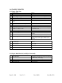
Table of Contents
Paragraph
Description
Page
Table of Contents
2
List of Amendments
4
1.0
1.1
Description
Denomination of Cylinders
5
8
2.0
2.1
2.2
2.3
2.4
2.5
2.6
2.7
Technical Data
Dimensions & Weights
Normal Equipment
Performance Data
Fuel Consumption
Fuel & Lubricant
Cooling System
Operating Speeds & Limits
9
9
9
9
9
9
10
10
3.0
Performance Graphs
11
4.0
4.1
4.2
4.3
4.4
4.5
4.6
4.7
Operating Instructions
Pre-Start Checks
Starting Procedure
Warm-Up Period, Ground Test
Take-Off
Engine Stop
Engine Stop & Start During Flight
Addition } Early Operation of Engine
12
12
12
12
12
13
13
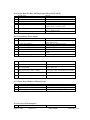
5.0
5.1
5.2
5.3
5.4
5.5
5.6
5.7
5.8
Checks on Engine & Installation
Daily Checks
Periodic Checks
Check After Initial 25 Hours
50 Hours Check
100 Hours Check
TBO
Engine Preservation
Operation in Winter
14
14
14
15
16
16
16
17
19
6.0
6.1
6.2
6.3
6.4
Maintenance
Lubrication System
Air Intake Filter
Carburettor Adjustment
Compression Check
21
21
21
21
21
Page No: 2
Issue No: 4
Date: 240103
Issued By: PJA
6.5
6.6
6.7
6.8
6.9
6.10
Spark Plugs
Exhaust System
Bolts & Nuts
Tappet Adjustment
Tachometer and Sender
Additional Checks
7.0
7.1
7.2
7.3
7.4
7.5
7.6
7.7
Service & Repair
24
Engine Overhaul and TBO
Engine Removal Procedure
Disassembly
2200 Engine Overhaul
1 Subassembly A - Crankshaft Prop Mount and Con rods
2 Subassembly B - Crankcase and Camshaft
3 Subassembly C - Pistons, Cylinders and Cylinder Heads
4 Subassembly D - Sump and Oil Pump
5 Subassembly E - Flywheel and Ignition Coils & Alternator
& Alternator Operation
6 Subassembly F - Gear Case
7 Subassembly G - Fuel Pump & Carburettor
& Carburettor Operation
8 Subassembly H - Final assembly of subassemblies
9 Run in
Engine Installation and First 25 hours
Prop Strike Inspection
Build Sheets and Run in programme
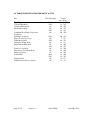
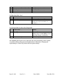
8.0
Table of Lubricants
87
9.0
9.1
9.2
9.3
9.4
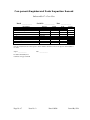
Torque Specifications
Prescribed Sealants and Primers
New Tolerances
Maximum Allowable Clearances (Wear Limits)
Electrical System Specifications
88
89
90
91
92
10.0
10.1
10.2
Trouble Shooting
Engine Won't Start
Engine Idles Unsteadily After Warm-Up
Period: Smoky Exhaust Emission
Engine Runs Erratically or Misfires Occasionally
Engine Runs Too Hot, Oil Temperature above 110oC (230oF)
Unsatisfactory Power Output
Low Oil Pressure
Engine Keeps Running with Ignition OFF
Excessive Oil Consumption
Knocking Under Load
Engine Hard to Start at Low Temperature
93
93
10.3
10.4
10.5
10.6
10.7
10.8
10.9
10.10
Page No: 3
Issue No: 4
22
22
22
23
23
23
Date: 240103
24
25
26
29
30
33
35
42
44
49
50
56
65
66
67
68
93
93
94
94
94
94
95
95
95
Issued By: PJA
11.0
Engine Warranty Form
Engine Warranty Form
102
103
List of Amendments
Page
Page No: 4
Amendment
Issue No: 4
Date
Date: 240103
Issue
Issued By: PJA
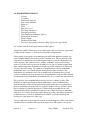
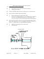
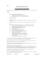
1.0 DESCRIPTION OF DESIGN
4 Stroke
4 Cylinder
Horizontally Opposed
One Central Camshaft
Pushrods
OHV
Ram Air Cooled
Wet Sump Lubrication
Direct Propeller Drive
Dual Transistorised Magneto Ignition
Integrated AC Generator
Electric Starter
Mechanical Fuel Pump
Pressure Compensating Carburettor (Bing Type 64\32 or type 94/40)
It is said that "aircraft are designed around available engines".
Jabiru believe that the Jabiru range of very light engines will now offer new opportunities
for light aircraft designers, to develop a new generation of light aircraft.
Jabiru engines are designed to be manufactured in small batch quantities using the very
latest Computer Numerically Controlled (CNC) machine tools. The vast majority of the
components are manufactured in Southern Queensland in a network of high technology
small companies. The crankcase halves, cylinder, crankshaft, starter motor housings,
gearbox cover (the gearbox powers the distributor rotors) and coil mounts together with
many smaller components are machined using the latest CNC machine tools. The sump
(oil pan) is the only casting. The cylinders are machined from solid bar 4140 chrome
molybdenum alloy steel, with the pistons running directly in the steel bores. The
crankshaft is also machined from solid bar 4140 chrome molybdenum alloy steel, the
journals of which are precision ground prior to being Magnaflux inspected. The camshaft
is manufactured from 4140 chrome molybdenum alloy steel. (journals and cams nitrided).
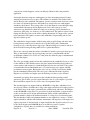
The propeller is direct crankshaft driven and does not use a reduction gearbox. This
facilitates its light-weight design and keeps maintenance costs to a minimum. The
crankshaft features a removable propeller flange which enables the easy replacement of
the front crankshaft seal and provides for a propeller shaft extension to be fitted, should
this be required for particular applications. Cylinder heads are machined from solid
aluminium billet which is purchased directly from one of Australia's largest aluminium
companies, as is all alloy used in the engine, thereby providing a substantive quality trail
to material source. Conrods are machined from 4140 alloy steel, the 45mm big end
bearings are of the automotive slipper type.
Various components of the engines are sourced from many Suppliers. These items include
camshaft followers, and the bendix gear in the starter motor. The ignition coils are also
Page No: 5
Issue No: 4
Date: 240103
Issued By: PJA
sourced from outside Suppliers, and are modified by Jabiru for their own particular
application.
An integral alternator using rare earth magnets, provides alternating current for battery
charging and electrical accessory drive. The alternator is attached to the flywheel and is
driven directly by the crankshaft. The ignition system is a transistorised electronic system;
two fixed coils mounted adjacent to the flywheel are energised by rare earth magnets
attached to the flywheel. The passing of the coils by the magnets creates the high voltage
current which is then transported by high tension leads to the centre post of two
automotive type distributors (which are simply rotors and caps) before distribution to
automotive spark plugs, two in the top of each cylinder head. The ignition system is fixed
timing and, therefore, removes the need for timing adjustment. It is suppressed to prevent
radio interference. The ignition system is fully redundant, self-generating and does not
depend on battery power.
The crankshaft is designed with a double bearing at the propeller flange end and a main
bearing between each big end; it therefore does not have flying webs. 48mm main
bearings are also of the automotive slipper type. Thrust bearings are located for and aft of
the front double bearing allowing either tractor or pusher installation.
Pistons are sourced in Australia and are re-machined to include a piston pin circlip groove.
They are fitted with 3 rings, the top rings being cast iron to complement the chrome
molybdenum cylinder bores. Valves are 7mm (stem dia) which are purpose manufactured
for the Jabiru engine.
The valve gear includes pushrods from the camshaft from the camshaft followers to valve
rockers which are CNC machined from steel plate, induction hardened and polished on
contact surfaces and mounted on a shaft through a teflon bronze-steel bush. Valve guides
are manufactured from aluminium/bronze, as is found in larger aero engines and high
performance racing engines. Replaceable valve seats are of nickel steel and are shrunk
into the aluminium cylinder heads. The valve gear is lubricated from the oil gallery.
Engines use solid lifters and require periodic checking of rocker to valve clearance.
An internal gear pump, direct mounted on the camshaft and incorporating a small
automotive spin-on filter, provides engine lubrication. An oil cooler adapter is provided.
Most installations require an oil cooler to meet oil temperature limits.
The standard engines are supplied with two RAMAIR cooling ducts, which have been
developed by Jabiru to facilitate the cooling of the engine and direct air from the propeller
to the critical areas of the engine, particularly the cylinder heads and barrels. The fitment
of these RAMAIR cooling ducts is a great bonus for the home builder or engine installer,
as they obviate the need to design and manufacture baffles and the establishment of a
plennum chamber, which is the traditional method of cooling air-cooled aircraft engines.
The fact that these baffles and plennum chamber are not required also ensures a "cleaner"
engine installation, which in turn facilitates maintenance and inspection of the engine and
engine component. So the hard work of engine installation has largely been done for you
by the Jabiru design team. RAMAIR ducts are available for tractor or pusher
configurations. Special ducts are available for certain installations.
Page No: 6
Issue No: 4
Date: 240103
Issued By: PJA
The engine is fitted with a 1.5 kw starter motor, which is also manufactured by Jabiru and
provides very effective starting. The engine has very low vibration levels,
however it is also supported by four large rubber shock mounts attached to the engine
mounts at the rear of the engine. An optional bed mount is available.
The fuel induction system comprises a BING pressure compensating carburettor.
Following carburation, the fuel/air mixture is transported through a swept plenum
chamber bolted to the sump casting, in which the mixture is warmed prior to entering
short induction tubes attached to the cylinder heads.
An effective stainless steel exhaust and muffler system is fitted as standard equipment,
ensuring very quiet operations, which in the Jabiru aircraft have been measured at 62dB at
1000' full power flyover (for 2200 engine).
For those owners wanting to fit vacuum instruments to their aircraft the Jabiru engine
design includes a vacuum pump drive, direct mounted through a coupling on the rear of
the crankshaft.
The Jabiru engine is manufactured within an Australian Civil Aviation Safety Authority
(CASA) approved Quality Assurance System to exacting standards.
Jabiru recommend a TBO of 1000 hours of engines to s/n 709. From s/n 710 TBO has
been extended to 2000 hours with a top end overhaul done at 1000 hours, certain
conditions do apply for this situation. A Guaranteed Fixed Price Overhaul Plan* is
offered with both engines. Contact your regional distributor or Jabiru Aircraft for details.
Top End overhauls are also available on later model engines.
Jabiru engine Warranty* is 200 hours or 12 months (whichever comes first) from date of
sale or from date of independently verified first flight.
*Conditions Apply
Page No: 7
Issue No: 4
Date: 240103
Issued By: PJA
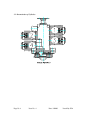
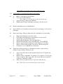
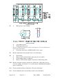
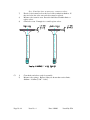
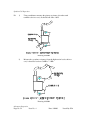
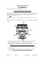
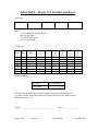
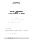
1.1 Denomination of Cylinders
Page No: 8
Issue No: 4
Date: 240103
Issued By: PJA
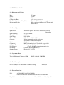
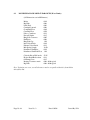
2.0 TECHNICAL DATA
2.1 Dimensions and Weights
Bore:
Stroke:
Displacement:
Compression Ratio:
Direction of Rotation on Prop Shaft:
Engine Curb Weight:
97.5 mm
74 mm
2209 cc
8.3:1 s/n 1004 onwards have 8:1
Clockwise Pilot's view, tractor applications.
60 kg complete with Engine Oil, Exhaust and
Starter Motor.
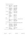
2.2 Normal Equipment
Ignition Unit:
Jabiru dual ignition - breakerless transistorised. Battery
Independent
25 degrees BTDC
1-3-2-4
NGK D9EA
0.55 - 0.6mm (0.022" - 0.024")
Jabiru, permanently excited single phase
AC generator with rectifier/regulator
10 amps (continuous)
BING constant depression Type 64/32 or type 94/40
1 x folder paper cartridge
0.1 mm (100 Micron) maximum particle size.
Camshaft driven diaphragm type
Electric 12 V / 1.5 kW
Ignition Timing:
Firing Order:
Spark Plugs:
Electrode Gap:
Generator:
DC Output:
Carburettor:
Air Intake Filter:
Fuel Filtration:
Fuel Pump:
Starting System:
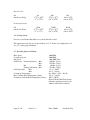
2.3 Performance Data
Take Off/Maximum Continuous RPM
60 kW (80 hp) @ 3300 RPM
2.4 Fuel Consumption
Fuel Consumption @ Takeoff/Max Continuous Rating
21 litres/hr
2.5 Fuel and Lubricant
Fuel:
Page No: 9
AVGAS 100 LL & AVGAS 100/130
Leaded and Unleaded Automotive Gasoline above 95 Octane Ron
Issue No: 4
Date: 240103
Issued By: PJA
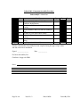
Run in Period
Oil
Outside Air Temp
80
-17oC to 25oC
(1o to 77oF)
100
15oC to 35oC
(59o to 95oF)
120
Above 35oC
(Above 95oF)
W80
-17oC to 25oC
(1o to 77of)
W100
15oC to 35oC
(59o to 95oF)
W120
Above 35oC
(Above 95oF)
Normal Operations
Oil
Outside Air Temp
2.6 Cooling System
Free air cooled. Ensure that baffles are correctly fitted & located.
The required pressure drop across the cylinders at 1.3 Vs in take off configuration is 4.3
cm (1.7") water gauge, minimum.
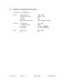
2.7 Operating Speeds and Limits
Max. Speed
Continuous Speed
Idle Speed:
Oil Pressure: Normal Operations
Min
Max
Idle
Min
Starting & Warm up Max
Oil Temperature:
Min.
Max.
Continuous Temperature:
Max. Cylinder Head Temperature (Climb)
Continuous Cylinder Head Temperature (Cruise)
3300 RPM
3300 RPM
900 RPM (Hot)
220 kPa (31 psi)
525 kPa (76 psi)
80 kPa (11 psi)
525 kPa (76 psi)
15 oC (59oF)
118 oC (244of)
80 - 100 oC (176o - 212oF)
175 oC (348oF)
150oC (302oF)
(Read Cylinder Head Temperature
under the spark plug nearest to the
exhaust on the hottest cylinder).
Page No: 10
Date: 240103
Issue No: 4
Issued By: PJA
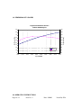
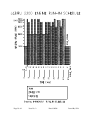
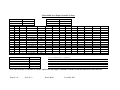
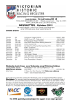
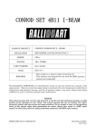
3.0 PERFORMANCE GRAPHS
90
160
80
150
70
140
60
130
50
120
40
110
30
100
20
Hp
Torque
10
0
1500
1700
1900
2100
2300
2500
2700
2900
3100
Torque (ft lbs)
Corr Power (Hp)
Engine Performance Curves
Jabiru 2200A Engine
90
80
70
3300
Speed (RPM)
4.0 OPERATING INSTRUCTIONS
Page No: 11
Issue No: 4
Date: 240103
Issued By: PJA
To ensure that the engine operates reliably, carefully observe all of the operating &
maintenance instructions.
4.1 Pre-Start Checks
Daily Checks (See Paragraph 5.1)
Move throttle position to FULL & check for ease of movement over the entire range.
4.2 Starting Procedure
Fuel Tap
Choke
Fuel Pump
Throttle
Master
Ignition
Starter
OPEN
ON (in cold conditions)
ON for 10 seconds then off
CLOSED to Stop
ON
BOTH ON
PRESS
Attention: Activate Starter for a max. 20 seconds, followed by a cooling period of 1
minute.
When engine runs, adjust throttle to achieve smooth running at approximately 1200 RPM.
Deactivate Choke. Check Oil Pressure has risen within 5 seconds - if not, shut down. It is
stongly advised to close choke while cranking on first attempt. To much choke will cause
over fueling in the venturi and loss of start. It is strongly recommended to crank the
engine to obtain oil pressure following an oil change before attempting to start.
4.3 Warming Up Period, Ground Test
Start the warming up period with the engine running at 1200 RPM. Continue at 2000
RPM depending on ambient temperature, until oil temperature reaches 15oC (59oF).
Check the two ignition circuits at 2000 RPM. Note: - RPM with only one ignition should
not drop by more than 100 RPM.
DO NOT apply full power until CHT reaches 100 oC (212oF)
DO NOT allow cylinder heads to rise above 150o during ground running.
4.4 Take-Off
Page No: 12
Issue No: 4
Date: 240103
Issued By: PJA
Climb with the engine at maximum continuous power. Observe Oil & Cylinder Head
Temperatures & Oil Pressure Limits must not be exceeded ! ( Max. continuous RPM at
Full Throttle is 3300 RPM ).
4.5 Engine Stop
In normal conditions, cooling down the engine during descent & taxiing will permit the
engine to be stopped by switching OFF the ignitions.
4.6 Engine Stop and Start During Flight
Reduce power to 2000 RPM to cool engine for 30 seconds, then to idle. Switch ignitions
OFF. Starting procedure is the same as ground starting, without choke for a warm engine
& with choke for a cold engine. Note: Engine cools quickly with propeller stopped in
flight. Choke will therefore normally be needed to restart.
Page No: 13
Issue No: 4
Date: 240103
Issued By: PJA
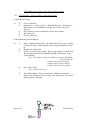
4.7
Addition} Early Operation of Engine
JA B IR U EN G IN E N O TES
NE W E NGI NE NOT E S :
T hi s engi ne has been gr ound r un to a s peci fi c r un i n pr ogr am and
i s r eady for fl i ght . I t has been I NH I B I T E D how ever i f you i ntend t o
s tor e for any l ength of ti me pl eas e r efer to 5 .7 S ecti on 3 of
I NS T R U CT I ON AND MAI NT E NANCE MANU AL . R emovi ng s par k
pl ugs and t ur ni ng over w i l l hel p per i odi cal l y. B efor e i ni t i al s tar t,
oi l engi ne 2 .3 l i t r es (w i t h cool er ) r emove one pl ug per head
act i vat e s t ar ter to r emove ex ces s i nhi bi tor . Once oi l pr es s ur e i s
obt ai ned r epl ace pl ugs and conti nue s t ar t -up s equence.
T he fol l ow i ng ar e ti ps to ens ur e a l ong l i fe.
1 . OI L
U s e a non-compounded AVI AT I ON oi l :¬ Aer o S hel l 1 0 0
¬ Mobi l R ed B and
¬ B P Avi ati on Oi l 1 0 0
U s e for 2 0 -2 5 hour s .
Dr ai n and r epl ace w i t h a compounded oi l :¬ Aer o S hel l W1 0 0
¬ Aer o S hel l 1 5 W5 0 (for cool er cl i mates )
¬ Mobi l Aer o 1 0 0 (S AE 5 0 )
¬ B P Aer o Oi l D1 0 0 /B P Mul t i gr ade Aer o Oi l D S AE 2 0 W 5 0
¬ Aer o S hel l W 1 0 0 P l us
T he nor mal r unni ng oi l s ar e deter gent and as hl es s di s per s ant
types . S ee MAI NT E NANCE S E CT I ON 5 .3
2 . Add
2 L i t r es (w i t hout oi l cool er )
2 .3 l i t r es (w i t h an oi l cool er )
3 . Avoi d pr ol onged gr ound r unni ng at el evated R P M. E ngi ne can
be over heated, r emember ai r duct s ar e des i gned for i n fl i ght
cool i ng. NOT E : r emove AL L pl as ti c bungs on engi ne.
E X H AU S T (4 ) CAR B Y (2 ) OI L VE NT (1 ) F U E L P U MP (1 )
4 . DO T AK E OF F AT F U L L P OWE R .
F or the fi r s t few tak e offs cl i mb at a hi gher ai r s peed. R educe
pow er at cr os s w i nd l eg and s hal l ow cl i mb (l ow er nos e).
Page No: 14
Issue No: 4
Date: 240103
Issued By: PJA
5 . VAR Y your R P M w hen fl yi ng.
6 . Avoi d hi gh nos e al ti t ude cont i nual cl i mbs . T he hi gher t he cl i mb
out s peed the better for engi ne cool i ng. No l ow s peed hi gh
nos e al ti tude cl i mb out s .
7.
R i ng bed i n i s accompl i s hed bet t er at 7 5 % pow er and above. Avoi d heat
bui l d up. Moni tor CH T and oi l temps . Var y R P M. I ni t i al t emps w i l l be
el evat ed due t o fr i ct i on of a new engi ne.
8 . CI R CU I T WOR K i s pos s i bl y a good s equence for i ni ti al r un i n
w or k . Abbr evi at e ci r cui ts i ni ti al l y, s tep cl i mb, cl i mb s hal l ow .
No gl i de appr oaches . Gr adual l y r educe pow er . Avoi d s udden
heat i ng up and s udden cool i ng dow n.
9 . R E T OR QU E heads as s ugges ted on w ar ni ng s heet .
2 4 ft l b and .0 1 0 ” val ve cl ear ance al l done col d. S ubs equent
tor qui ng of ar ound 2 2 to 2 4 s eems to hel p i n s ett l i ng dow n
head bol ts and heads .
1 0 . Don’t B AB Y Y OU R E NGI N E but moni t or car eful l y CH T and oi l
t emp i ni t i al l y es peci al l y dur i ng t he fi r s t few hour s of
oper ati on.
R emember engi nes need t o be fl ow n. T hey ar e des i gned for
t hi s pur pos e. Do not us e ful l pow er befor e CH T r eaches 1 0 0 oC.
T he pur pos e of br eaking in an engine cor r ect ly is t o ens ur e a long r eliable
lif e. All moving par t s need f r eeing up es pecially pis t on r ings t o cylinder
w alls . T his is bes t accomplis hed w hen t he gr eat es t B .M.E .P . (B r eak Mean
E f f ect ive P r es s ur e) occur s . T hat is at 7 5 % pow er and above. Car ef ul
monit or ing by t he pilot is needed dur ing t his init ial per iod t o ens ur e long lif e
of t he engine and it s component s .
F ai l ur e to oper at e at r eal i s ti c pow er s et ti ngs coul d be
det r i ment al to engi ne condi ti on.
Page No: 15
Issue No: 4
Date: 240103
Issued By: PJA
1 1 . Do not us e any type of aut omoti ve oi l . T hes e oi l s have not
been bl ended for t he pur pos e of ai r cool ed aer o engi ne
oper ati on and w i l l be det r i ment al t o i ts oper ati on.
1 2 . U s e AVGAS 1 0 0 L L or the hi ghes t Octane Mogas above 9 5
cont ai ni ng l ead. E ngi nes not s hi mmed on the cyl i nder bas e
s houl d onl y be r un on AVGAS .
1 3 . When you change oi l fr om the “r un i n” type to t he “nor mal ” oi l
at or ar ound 2 5 hr s r epl ace oi l fi l ter . Y ou may w ant t o cut the
fi l ter open for i ns pecti on. I t i s us ual i n J abi r u engi nes to fi nd
a s mal l amount of al umi ni um but defi ni tel y no metal . I f
bear i ng met al i s pr es ent contact the J abi r u S er vi ce
Depar t ment.
1 4 . Wi t h i gni t i on and mas ter OF F and thr ott l e cl os ed tur n t he
pr op by hand and obs er ve engi ne for odd noi s es or heavy
movement s .
Check for r egul ar compr es s i ons , i f i r r egul ar fi r s tl y check
tappet adj us t ment. Oper at i on w i th i ncor r ectl y adj us ted
tappets w i t h r es ul t i n damage to val ves , val ve s eat s , gui des
and over head gear .
HEAD TORQUING/VALVE SETTING
Y our t ens i on w r ench s houl d be accur at e. I t s houl d have had s ome
met hod of cal i br ati on. T hey can var y t o manufact ur er s cl ai ms .
2 4 f t lb on head bolt s
.0 1 0 ” on valve clear ance cold
E ar l y heads r equi r e a 1 /2 i nch r i ng s panner and 3 /1 6 al l en k ey.
L at er engi nes us e a 9 /1 6 s ock et and 3 /1 6 al l en k ey or bl ade
s cr ew dr i ver .
E as i es t method of s et ti ng val ves r equi r es you to pul l the pr op
unt i l ex haus t val ve on No.1 cyl i nder i s ful l y depr es s ed. Not e t he
O’cl ock pos i ti on. R ot ate pr op 3 6 0 o and adj us t val ve. (T hi s puts the
cam and l i ft er at 1 8 0 o t o the peak l i ft). R epeat for each val ve.
H eads and val ves s houl d be done at l eas t tw i ce at 5 hr s and 1 0
hr s on a new engi ne.
Page No: 16
Issue No: 4
Date: 240103
Issued By: PJA
R emember to go over ex haus t cap s cr ew s . T hey ar e fi tt ed w i th
s hak epr oof w as her s to pr event l oos eni ng.
AIR DUCTS
P er i odi c r es ear ch and devel opment does caus e at t i me changes
to occur . Ones s uppl i ed need t o be fi tt ed. S ee i ns tr ucti ons
manual .
FILTERS
I ns pecti ons dow n the t r ack ar e a mus t for fuel and ai r fi l ter s .
Condi ti ons w i l l di ct ate w hen changed. T he ai r box has a r ubber
fl ap to gi ve par t i al i ns pecti on of fi l t er .
SPARK PLUGS
NGK D9 E A ar e r ecommended.
P l ug gap of ar ound .0 2 2 ” to .0 2 4 ”. R emember pl ugs ar e i ns tal l ed
at ar ound 8 ft l b or gi ven 1 /2 t ur n aft er contact w i t h head.
1 8 mm P l ug s panner us ed.
COMPRESSION TESTING
Condi ti on of compr es s i on can be done by a compr es s i on gauge.
Wi de open thr ott l e, engi ne w ar m. T ur n over on s tar ter . B el ow 9 0
P S I w oul d i ndi cate r emoval of head and pos s i bl y cyl i nder .
P R E S S U R E DI F F E R E NT I AL T E S T (L eak dow n)
T hi s i s a much bett er tes t for condi ti on of r i ngs , bor e, head
s eal i ng and val ve. E ngi ne i n w ar m to hot condi t i on. T hi s i s t he
nor mal tes t us ed i n avi at i on r equi r i ng s peci fi c equi pment for t he
j ob. P r es s ur e i nput of 8 0 P S I ; a s econd gauge r eads the
di ffer ent i al w hen s uppl yi ng 8 0 P S I . T hi s i s done w i th pi s ton on
T DC on t he fi r i ng s tr ok e. P r op needs to be r es tr ai ned. T he
di ffer ent i al cut off i s 8 0 /6 0 . P r obl ems can be bet ter i denti fi ed eg.
¬
¬
¬
¬
B L OW B Y (CR ANK CAS E VE NT ) - R I NGS , B OR E S E AL
L E AK I NG F R OM CAR B Y - I NT AK E VAL VE S E AL
L E AK I NG F R OM E X H AU S T - E X H AU S T VAL VE S E AL
H E AD L E AK - H E AD GAS K E T OR H E AD T O CY L I NDE R S E AL
Cor r ecti on w or k can then be car r i ed out.
COIL GAP
B es t done w i th a pi ece of pl as ti c or thi n car d of a t hi ck nes s .0 1 0 ”.
Cut i nt o a s tr i p appr ox i matel y 1 5 mm w i de.
Page No: 17
Issue No: 4
Date: 240103
Issued By: PJA
P l ace bet w een magnets on fl yw heel and coi l . Check bot h s i des ,
that i s each coi l to each magnet (4 check s ).
STARTING
A w ar m i dl e of ar ound 9 5 0 R P M w i l l aut omat i cal l y cr eat e the r i ght
s tar t i ng envi r onment. I dl e s et s cr ew may have t o be adj us ted.
Car by has been factor y s et . Nor mal s t ar t r equi r es thr ott l e cl os ed,
that i s the i dl e cr i t er i a has j us t cr ack ed the butter fl y i n the t hr oat
body and al s o appl y chok e. T he engi ne i s di ffi cul t t o s t ar t i f
thr ott l e i s cr ack ed open s omew hat.
As t he engi ne i s cr ank ed t he chok e s houl d be pus hed off. E ngi ne
s houl d fi r e. T he chok e i s onl y us ed for a col d s tar t. P r ol onged
cr ank i ng w i th chok e w i l l onl y “fl ood” the i ntak e s ys tem mak i ng
s tar t i ng di ffi cul t . S houl d t hi s occur , l eave or cl ear the s ys tem on
ful l thr ot tl e momentar i l y (mags off). Cr ank i ng s peed i f too s l ow
(poor batt er y or s tar ter faul t) w i l l pr event magnet o oper ati on.
J ump s tar ti ng (w i th car e) w i l l poi nt tow ar ds poor batt er y
condi t i on or faul ty al ter nat or char gi ng. F ur ther t es t i ng w oul d then
be r equi r ed i n thes e ar eas to i denti fy the pr obl em.
POSSIBLE PROBLEMS
S ee “T r oubl e S hooti ng” S ecti on of 1 0 .0 of Mai ntenance Manual .
I t i s unus ual for a pr obl em to occur how ever a few of “common”
type ar e l i s ted.
1 . L OW OI L P R E S S U R E
A s udden dr op of pr es s ur e us ual l y i s caus ed by a s mal l pi ece of
for ei gn matt er bei ng l odged under t he r el i ef val ve. S i mpl y r emove
oi l fi l t er and cool er adaptor (i f fi t ted). R emove matt er by
depr es s i ng pl unger or r emovi ng r el i ef mechani s m. R epl ace and
check oper at i on by gr ound r un. I f l ow pr es s ur e per s i s ts the
pr obl em w i l l need fur ther i nves t i gat i on.
We s tr ongl y r ecommend the fi tti ng of an appr oved oi l cool er to
J abi r u engi nes .
2 . F L I CK I NG OF OI L P R E S S U R E GAU GE
I t i s not uncommon for the J abi r u engi ne t o di s pl ay fl i ck i ng of t he
needl e poi nter for br i ef per i ods but s ti l l w i t hi n nor mal oper ati ng
Page No: 18
Issue No: 4
Date: 240103
Issued By: PJA
r egi ons . I f i t conti nues , check cont i nui ty of s ender l ead and or
pos s i bl e s ender change. (We ar e as s umi ng oi l l evel i s OK ).
3 . CH T
P os s i bl e not r eadi ng can be caus e by a br eak i n the s ender w i r es
or i ncor r ect pol ar i t y. H i gh r eadi ngs can r es ul t w i t h poor l y centr ed
s ender under t he s par k pl ug. Nor mal cr ui s e CH T s houl d not
ex ceed 1 5 0 oC and cl i mb mus t not ex ceed 1 7 5 oC. Ai r ducts
s uppl i ed at pr es ent gi ve r es ul ts bel ow thes e fi gur es .
4. R P M
T acho’s may need adj us t ment w hen a new engi ne i s fi tt ed.
I nduct ed magnet s ender uni t s r equi r e coi l gap to fl yw heel gear
teeth of .0 1 4 ” or .3 5 mm. T acho’s us i ng thi s s ender r equi r e a “pot ”
adj us tment, acces s thr ough out s i de of cas e.
T acho’s us i ng the magnet o as s ender r equi r es a s equence of
oper ati on for cor r ect i on. T hi s i nfor mat i on can be fax ed i f
r equi r ed.
L at er engi nes us e 2 t ags under t he r i ng gear i n conj unct i on w i th
the i nduct i on s ender .
5 . MAGNE T O CH E CK S
P os s i bl e caus es of abnor mal dr op coul d be l oos e l eads , faul t y
l eads , r otor butt ons , coi l gaps , s par k pl ugs .
6 . R OU GH CY L I NDE R R U NNI NG
Check pl ugs /val ve cl ear ance and t he i nduct i on s ys tem for
l oos enes s .
7 . CAR B Y B R E AT H E R
L at er model car bi es have a br as s fi tt i ng for venti ng. T hi s i s eas i l y
connected vi a a cl ear pl as ti c hos e t o a fi tt i ng s cr ew ed i nt o the
car by heat box . On ear l i er car bi es w e s uppl i ed a k i t for t hi s
pur pos e as no i nter nal car by fi tt i ng w as i ns tal l ed.
8 . L I MI T AT I ONS
War r ant y notes fol l ow .
J abi r u r ecommend T B O of 1 0 0 0 hr s . F r om s /n 7 1 0 T B O has
i ncr eas ed to 2 0 0 0 hour s w i th T op E nd at 1 0 0 0 . A guar ant eed
fi x ed pr i ce
Page No: 19
Issue No: 4
Date: 240103
Issued By: PJA
over haul ex i s t s t hr ough the J abi r u fact or y. War r ant y i s 2 0 0 hour s
or 1 2 mont hs w hi ch ever comes fi r s t .
CAR E F U L L Y R E AD MANU AL S S U P P L I E D
Page No: 20
Issue No: 4
Date: 240103
Issued By: PJA
5.0 CHECKS ON ENGINE & INSTALLATION
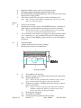
5.1 Daily Checks
* Ensure free movement of throttle & choke cables.
* Check Oil Level, replenish if necessary. Oil level should be between the MAX & MIN
marks - but must never be below the MIN mark. Before long periods of operation,
ensure that the level is at least at the mid position. Difference in the oil quantity between
MAX & MIN mark is 0.5 litres (0.528 US Quarts). See section 4.7 for first 25 hours of
Operation. Check oil level by screwing in cap fully before withdrawing. Overfilling is
detrimental to the engine.
* Check security of spark plugs, leads & electrical connections.
* Check lubrication & fuel system for leaks.
* Check exhaust system for security & leaks.
* With Ignition & Master OFF, and throttle closed, turn propeller by hand & observe
engine for odd noises or heavy movements. Check for regular compression. If irregular,
firstly check tappet adjustment (see para 6.8).
IMPORTANT
Prior to pulling through the propeller by hand, both ignition circuits & the Master must be
switched OFF, the brakes applied, throttle closed & the cockpit attended by a trained
person.
WARNING
A hot engine may fire with the ignition/s switched OFF.
CAUTION
Continued operation with incorrectly adjusted tappets will result in damage to valves,
valve seats, valve guides & overhead gear. Head torque and valve adjustment at 5/10 hrs
from initial start up.
* Prior to takeoff - follow the Starting & Warm Up procedure, observe the engine
behaviour & throttle response.
* Check temperatures & pressures. Conduct a short ground test at full power (a few
seconds) (consult aircraft Flight Manual). NOTE: Any prolonged running at full power
can cause engine damage while on the ground. Continual operation with leaky valves or
partially sealing exhaust gaskets will result in engine damage.
5.2 Periodic Checks
After the initial 25 hours, check in accordance with para. 5.3.
Page No: 21
Issue No: 4
Date: 240103
Issued By: PJA
After 50 hours of operation, check in accordance with para. 5.4 & thereafter after each 50
hours of operation.
After 100 hours of operation, check in accordance with para. 5.5 and thereafter after each
100 hours of operation.
At TBO, overhaul in accordance with para. 5.6.
5.3 Check After Initial 25 Hours
Details of specific operations are shown in Chapter 6 "Maintenance".
* Remove engine cowlings, check engine mounts.
* Thoroughly check engine for missing or loose bolts, nuts, pins, etc., & for abrasions.
* Check induction and exhaust flange for loose bolts.
* Check safety wires, cooling air ducts & baffles, ignition wiring & hose connections.
* Oil Change 2.0 litres. Use normal aviation running oil.
* Change oil filter. (First 25 hours only)
* Inspect old filter.
* Retorque cylinder head bolts (24 ft lbs) in diagonal pattern
* Check tappet clearance and adjust as necessary (refer Para 6.8).
(0.010" cold inlet and exhaust)
* Check exhaust system, check exhaust cap screw tensions and gasket condition.
* Check fuel system for leaks & abrasion.
* Check wiring for damage & for tightness.
* Engine test run.
Observe starting, warm up & acceleration behaviour to maximum RPM (10
seconds max)
Check temperatures & pressures.
Engine stop.
Page No: 22
Issue No: 4
Date: 240103
Issued By: PJA
5.4 50 Hours Check
Details of specific operations are shown in Chapter 6 "Maintenance".
* Conduct the items shown under 25 Hour Check at para. 5.3.
5.5 100 Hours Check
Details of specific operations are shown in Chapter 6 "Maintenance".
* Conduct the items shown under 25 Hour Check at para. 5.3.
* Renew spark plugs, if necessary.
5.6 TBO
Details of specific operations are shown in Chapter 6 "Maintenance".
* Engine Overhaul, in accordance with Service Bulletins
* Conduct the items shown under 25 Hour Check at para. 5.3.
* Check clearance on throttle valve shaft. If radial clearance exceeds 0.5mm (0.020"),
repair carburettor.
The overhaul work must be carried out to Jabiru specifications at an approved aeronautical
service facility or by an approved Jabiru Service Centre.
If necessary, changes to the TBO Limit due to operational experience, will be announced
by Jabiru in a Service Bulletin.
Page No: 23
Issue No: 4
Date: 240103
Issued By: PJA
5.7 Engine Preservation
The following procedures assume that the engine is installed in a Jabiru LSA airframe. For
other aircraft types, refer to the manufacturer's service manual. If the engine is not fitted to
an airframe, ignore those items referring to the airframe.
5.7.1 Flyable Storage
Flyable storage is defined as a maximum of 30 days non-operational storage.
Ensure that the engine has been stopped by turning off the fuel valve, thereby not leaving
any fuel in the carburettor bowl.
Every 7th day the propeller should be rotated through 5 revolutions, without running the
engine. Leave the propeller in the horizontal position to ensure even distribution of liquids
in the wood. If left in the vertical position, liquids will drain to the lower tip resulting in
an unbalanced propeller.
CAUTION
Ensure that the Master and Ignition Switches are OFF!
5.7.2 Returning Engine to Service
After flyable storage, returning the engine to service is accomplished by performing a
thorough pre-flight inspection. Ensure all protective covers are removed.
5.7.3 Temporary or Indefinite Storage
Temporary storage is defined as aircraft in non-operational status for a maximum of 90
days.
Treat as for flyable storage (see Paragraph 5.7.1), plus:
- For temporary storage, fill fuel tank with correct grade of fuel (to prevent
moisture accumulation).
- For indefinite storage, drain fuel tank, ensure carburettor bowl is empty by
running engine with fuel valve off until it stops or by draining bowl.
Then:
1. Disconnect spark plug leads and remove spark plugs from each cylinder.
2. Using a spray atomiser, spray the oil through the spark plug hole with the piston down,
then rotate until both valve are open and respray to coat the induction and exhaust
system. When all cylinders are treated leave prop horizontal and retreat each cylinder.
Page No: 24
Issue No: 4
Date: 240103
Issued By: PJA
NOTE: Use Shell Aero fluid 2UN (MIL-C-6529C Type 1) Corrosion Preventive
Concentrate or similar engine preservative.
CAUTION
Ensure that the Master and Ignition Switches are OFF!
3. Install spark plugs and connect leads.
4. Seal exhaust pipes. Attach a red streamer to each seal. DO NOT seal fuel tank
breather.
5. Attach a warning placard to the propeller stating that vents and breathers have been
sealed and prop should not be turned.
The engine must not be started with the seals in place.
5.7.4 Inspection During Storage
1. Generally inspect airframe and clean as necessary.
2. Inspect the interior of at least one cylinder through the spark plug hole for corrosion at
least once a month.
3. If, at the end of the 90 day period, the aircraft is to be continued in non-operational
storage -- repeat Steps 1-5 above (most will only need to be checked).
5.7.5 Returning Engine to Service
After temporary storage, the procedures for returning the aircraft to service are as follows:
1. Check battery and install.
2. Check carburettor air filter and service if necessary.
3. Remove warning placard from propeller.
4. Remove materials used to cover openings.
5. Remove, clean and gap spark plugs.
6. While spark plugs are removed, rotate propeller several revolutions to clear excess
preservative oil from cylinders.
CAUTION
Ensure that the Master and Ignition Switches are OFF!
8. Install spark plugs -- torque to 11 Nm (8 ft/lbs).
Page No: 25
Issue No: 4
Date: 240103
Issued By: PJA
9. Check fuel filter -- replace if necessary.
10. If returning to service after indefinite storage, fill fuel tank with correct grade of fuel.
11. Check fuel tank and fuel lines for moisture and sediment. Drain enough fuel to
eliminate any moisture and sediment.
12. Check fuel tank breather is clear.
13. Perform a thorough pre-flight inspection.
14. Start and warm engine.
5.8 Operation in Winter
It is recommended to carry out an engine service prior to the start of the cold season.
For selection of oil, consult the table of lubricants at Paragraph 2.5.
Follow the following advice for operation at extremely low temperatures:
5.8.1 Carburettor Icing
It is important to distinguish between two kinds of icing:
1) Icing due to water in fuel, and
2) Icing due to high air humidity.
Re 1)
Water in fuel will accumulate at the lower parts of the fuel system & can lead to freezing
of fuel lines, filters or jets. Remedies are:
- Drain, using fuel tank water drain.
- Ensure fuelling without traces of water. If in doubt, use a chamois as a filter.
- Install a generously sized water separator.
- Ensure that fuel lines do not permit the accumulation of water.
- Add up to 2% isopropyl to fuel. Note: Addition of alcohol raises vapour pressure
and may aggravate vapour lock in warm weather; this practice should be used
only when needed and not in warm weather.
- Prevent condensation of humidity, ie avoid temperature differences between the
aircraft & fuel.
Page No: 26
Issue No: 4
Date: 240103
Issued By: PJA
IMPORTANT
Fuels containing alcohol always carry a small amount of water in solution. In situations
where there are changes in temperature, or where there is an increase in alcohol content,
water (or a mixture of water & alcohol) may settle & could cause problems.
Re 2)
Carburettor icing due to humidity may occur in the carburettor venturi & leads to
performance loss due to changes in the mixture.
The only effective remedy is to preheat the intake air by use of the Carburettor Heat
Control.
WARNING
When using auto fuels, ensure all components of the fuel delivery system are cooled to
prevent fuel vaporization.
Page No: 27
Issue No: 4
Date: 240103
Issued By: PJA
6.0 MAINTENANCE
6.1 Lubrication System
Oil Change, Oil Filter Change, Visual Check for Leaks.
* Drain the oil while engine is still warm.
* Change the oil filter at 100 hour inspection.
* Fill with oil. Capacity is 2.3 litres (2.43 US Quarts)
* Check oil level. The MAX mark must not be exceeded.
* Use only registered brand oils meeting the specification detailed in Para. 2.5.
6.2 Air Intake Filter
Clean filter by removing from the intake housing & blowing compressed air against the
direction of the intake flow.
For operation in heavy dusty conditions, clean air filter at shorter intervals than
recommended for normal conditions.
A clogged filter will reduce engine performance as well as promote premature engine
wear.
6.3 Carburettor Adjustment
Idle stop screw is 7mm against throttle lever.
Open idle mixture screw approximately 1-1/4 turns, fine adjust for a smooth idle. The
determination of the main jet is carried out on a dyno at 107 ft above Mean Sea Level.
IMPORTANT
Check & oil carburettor joints & linkage
6.4 Compression Check
Measure compression using a compression tracer. Readings are taken with fully open
throttle valve at engine oil temperature between 30 & 70 degrees C (90 to 160 degrees F).
Page No: 28
Issue No: 4
Date: 240103
Issued By: PJA
If readings are below 6 bar (90 psi) a check of the pistons, cylinders, valves & cylinder
heads must be undertaken.
Alternatives:
* Pressure loss or leakage tester eg SUN or BOSCH tester; max. allowable pressure loss
is 25%.
* Checking by commonly used pressure difference method; place orifice of 1 mm ID and
3mm length between the two pressure gauges. This will give the same result as with the
above instrument. Max. pressure drop is 25%.
6.5 Spark Plugs
Do not use steel or brass brushes for cleaning & never sandblast plugs.
Clean with plastic brush in a solvent.
Check electrode gap & if necessary, adjust to 0.55 - 0.6mm (0.022" - 0.024") by carefully
bending the electrode. Recommended Plugs: NGK D9EA use suitable anti-seize on
thread.
IMPORTANT
Only tighten spark plugs on cold engine & only to the torque values shown in para. 9.0
using appropriate anti-seize compound
Note: When plugs are removed from a warm engine, the following are indicators:
Light Coloured to Brown :- Plug & calibration is correct.
Velvet Black:- Mixture too rich. Check choke. Insufficient air intake. Check for
clogged air filter.
Oily, Glossy Coating:- Misfiring. Too much oil in combustion chamber. Worn
cylinder & piston rings.
Whitish with Melt Droplets:- Mixture too lean. Leaking valves.
6.6 Exhaust System
Visual check for damage, leaks & general condition.
6.7 Bolts and Nuts
Check for tightness, re-torque if necessary (see para. 9.0).
Page No: 29
Issue No: 4
Date: 240103
Issued By: PJA
6.8 Tappet Adjustment
Tappets must be adjusted to: Inlet
Exhaust
0.254mm (.010")
0.254mm (.010")
Adjust the tappets when the engine is cold. Head torqued to 24 ft.lb. when cold. Carry out
this adjustment after five hours of operation and again after ten hours of operation. At the
25 hour inspection this is done again. There is no need to back off studs when checking,
we are trying to check if movement has occurred and seal of cylinder to head is in tact.
Bolts in the exhaust area may move on checking.
CAUTION
Continued operation with incorrectly adjusted tappets will result in damage to valves,
valve seats, valve guides & overhead gear.
6.9 Tachometer and Sender
Many apparent engine problems can be caused through inaccurate tachometers. Where
engine performance is observed to be outside limits, the tachometer should be checked
against a calibrated instrument. Tachometer sender gap is 0.4mm (0.016"). When using
two tags behind flywheel sender must have at least 60% covering by the tag. Ensure both
tags are equal distance from sender.
6.10 Additional Checks
Check engine for ease of starting. Conduct idle test run.
Page No: 30
Issue No: 4
Date: 240103
Issued By: PJA
7.0 SERVICE & REPAIR
7.1 Engine Overhaul and TBO
These are carried out only by the manufacturer, Jabiru Aircraft Pty Ltd or by a specifically
approved Jabiru Engine Service Centre (contact Jabiru for details).
The engine must be sent in a complete state, with logbook, to Jabiru (or the Approved
Service Centre) after reaching the TBO limit.
Changes to the TBO due to operational experience will be advised by Jabiru through
Service Bulletins.
It is recommended that engines prior to s/n 710 have full overhauls at or before 1000
hours. Very early engines were at 500 hours. Engines after s/n 710 have full overhauls at
2000 hours with a Top End being done at around 1000 hours. This is also subject to
certain conditions. Overhauls are influenced by condition.
Page No: 31
Issue No: 4
Date: 240103
Issued By: PJA
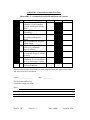
7.2
ENGINE REMOVAL PROCEDURE
No.
Operation
Tools
1
Remove Spinner and Propeller
Phillips Screwdriver
7/16" Socket
7/16" Spanner
2
Remove Carby Heat hose from Hot Box Muffler
Screwdriver
3
Remove Air Inlet Hose from Carburettor and blank
off Carburettor and Air Cleaner
Screwdriver
2 Plugs
4
Disconnect Throttle Cable
Long Nose Pliers
5
Disconnect Choke Lever
Long Nose Pliers
6
Remove Oil Breather Line
Screwdriver
7
Remove Fuel Line from Fuel Pump and plug Fuel
Line and Fuel Pump
Screwdriver
1/4" Plugs
8
Remove starter Motor Cable from Solenoid
7/16" R/OE
9
Disconnect Earth at Battery
10mm R/OE
10
Remove Oil Pressure Gauge Lead
-
11
Remove Oil Temperature Gauge Lead
-
12
Remove Hourmeter Lead
Screwdriver
13
Remove Cylinder Head Temperature Gauge Lead
-
14
Remove Exhaust Gas temperature Gauge Lead
-
15
Remove Tacho Lead
-
16
Remove Left and Right Ignition Coil Leads
-
17
Remove Muffler Assy
3/16" Ball End Allen
Key
18
Undo Engine Mount Bolts
7/16" Tube Socket
7/16" Spanner
19
Remove Engine from Engine Mount Frame
-
Page No: 32
Issue No: 4
Date: 240103
Issued By: PJA
7.3
ENGINE DISASSEMBLY
No.
Operation
1
Mount Engine on an engine stand in vertical position
2
Remove Spark Plugs
Spark Plug Socket
3
Remove Oil Pressure Sensor
17mm Spanner
4
Remove Oil Filter
-
5
Oil Pressure Valve may be removed by removing
snap ring (1)
Snap Ring Pliers
6
Extract Valve Seat (1), Valve (1), Spring (1)
-
7
Remove Oil Pump Assembly (Housing, Rotor, Stator
& Backing Plate)
7/32" Allen Key
8
Remove 4 capscrews in front oil seal carrier and break
seal on crankcase
3/16" Allen Key
9
Remove Fuel Line and Carburettor
Screwdriver
10
Remove Fuel Pump, Gasket and Push Rod
7/32" Allen Key
11
Remove Distributor Cap Clamps, Caps and Rotors
5/32" Allen Key
12
Remove Starter Motor
7/32" Allen Key
13
Remove Alternator Mount
7/16" Socket
5/16 Ring O/End
Spanner
14
Remove Ignition Coils from Alternator Mount
3/16" Allen Key
15
Remove Flywheel
3/16" Allen Key
16
Remove Gearbox Cover
3/16" Allen Key
17
Remove Engine Mount Plate
7/32" & 3/16" Allen
Key
18
Remove Crankshaft Timing Gear
-
19
Remove Lower Induction Pipes
Screwdriver
Page No: 33
Tools
Issue No: 4
Date: 240103
Issued By: PJA
20
Remove Sump
3/16" Allen Key
21
Remove Exhaust and Induction Pipes
22
Remove Tappet Covers
3/16" Allen Key
23
Remove Rocker Blocks and Push Rods
(From S/N 225 rocker blocks were not used)
1/2" Spanner
1/2" Socket
5/32" Allen Key
1/4" Allen Key
24
Remove Cylinder Head
7/32" Allen Key
1/2" Socket
25
Remove Push Rod Tubes
-
26
Remove Cylinder
7/16" Crowsfoot
3/16" Allen Key
Removal of Piston
27
Remove 1 Wrist Pin Circlip
Long Nose Pliers
28
Remove Wrist Pin (keep pin matched with its piston)
-
29
Remove Piston Rings (keep rings matched with its piston) -
30
Repeat Operations 27-30 on other pistons if required.
-
Crankcase Disassembly
31
Remove main Stud Nuts on Front 2 studs
7/16" Socket
32
Double check that every bolt is removed and sump,
gear case engine mount plate, oil pump and
Front Oil Seal Carrier is removed
-
33
Tap Crankcase slightly and open Crankcase by
removing half Crankcase
Plastic Mallet
34
Remove both Crankcase Halves of Crankshaft and
Remove Cam Shaft
-
35
Remove Valve Lifters (8)
Note - Keep valve lifters matched to each
Crankcase half.
-
36
Remove Thrust Washers (front and rear)
- 2 without tang on right half case
Page No: 34
Issue No: 4
Date: 240103
Issued By: PJA
- 2 with tang on left half case
Note - visually check for marks or scratches
- keep matched to their seats
-
37
Remove Main Bearing Inserts (12)
Note - visually check for marks or scratches
- keep matched to seats
38
Remove Crankcase dowels. Remove O'Rings and Discard Note - do not attempt to remove studs as they
are loctited in with 620 loctite
39
Remove Oil Gallery Plugs and Oil Pressure Sender.
Remove Oil Relief Valve.
Cylinder Head Disassembly
40
Remove Valve Springs and Valves
41
-
-
Valve Spring
Compressor
Remove Push Rod Circlips and O'Rings
Internal Circlip Pliers
Gearbox Cover Disassembly
42
Remove Distributor Shafts
-
43
-
Remove Oil Seals
Crankshaft & Camshaft Disassembly
44
Remove Bolts from Conrod
¼ allen key/10mm
Socket
Note - Rods will need to be heated
3/8 Ratchet
- Big End Bolts are Discarded on Removal Hot Air Gun Rags
45
Remove Rod Bearing Inserts
Note - visually inspect for marks and scratches
- keep matched to their seats
46
Remove Camshaft Gears. Discard Camshaft Bolts.
Remove welsh plug in rear of camshaft.
7.4
2200 ENGINE OVERHAUL
-
Inspection and Assembly of Sub-Assemblies
Page No: 35
Issue No: 4
Date: 240103
Issued By: PJA
1
Sub-Assembly A - Crankshaft, Prop Mount and Con Rods.
2
Sub-Assembly B - Crankcase and Camshaft.
3
Sub-Assembly C - Pistons, Cylinders and Cylinder Heads.
4
Sub-Assembly D - Sump and Oil Pump
5
Sub-Assembly E - Flywheel, Ignition Coils and Alternator
6
Sub-Assembly F - Gear Case
7
Fuel Pump and Carburettor
8
Final Assembly of Sub-assemblies
9
Run In:
Engines can be run in statically using suitable mount structure and very
large
specially constructed air ducts or in the airframe in flight with extreme care. Run
In program can be found at the end of the build sheets (see also early run notes
section 4.7).
10.
Overhaul:
The overhaul of any engine is an exacting science. Approved Jabiru
centres as well as Jabiru can provide this service.
Page No: 36
Issue No: 4
Date: 240103
service
Issued By: PJA
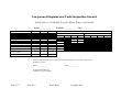
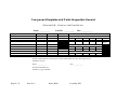
Jabiru 2200 Component Inspection and Assembly Procedure
7.4.1
Sub-Assembly A - Crankshaft, Prop Mount and ConRods
A1
1)
2)
3)
4)
Remove welsh plugs from crankshaft
Clean conrods and crankshaft
Note - Make sure all old loctite is removed from threads
Strip paint off prop flange and crankshaft.
Magnet particle inspect crankshaft , prop flange, cam and conrods.
A2
Measure crankshaft and record in Build Sheet.
A3
Inspect Oil Holes for Cleanliness and insert new front welsh plugs (2 off) and rear
welsh plug.
A4
Inspect prop flange. Paint prop flange and end of crankshaft to prevent rusting.
A5
1)
2)
3)
4)
5)
6)
7)
8)
A6
Temporarily mount prop flange to crankshaft and mount to stand vertically.
(Flange is removed later to fit front oil seal)
A7
1)
2)
3)
Magnet particle Inspect conrods for cracks.
Fit bearings with a light smear of bearing blue on back of shells.
Torque Caps to 18 lbs (with new bolts)
Measure Big End Bearings. Record in Build Sheet.
Measure Piston Pin Bore. Record in Build Sheet. Check CRUSH.
Remove caps and check bearing back contact (Must be at least 90%)
Remove all blue and thoroughly clean surfaces. Refit bearing shells.
Clearance as close to 0.05mm is recommended.
Spray conrod bolts and conrod bolt threads with Loctite 7471 primer and
allow to dry.
Mount conrods to crankshaft. Use plenty of oil on journals. Closest to prop
flange is number 1. Pins to prop drive. Use Loctite 620 on rods and bolts
torque up to 24.0 NM (18 ft/lbs)
Wipe off excess locktite at bases of cap screws on the end cap.
Note: Alloy rods are not reused but replaced with steel type
Page No: 37
Issue No: 4
Date: 240103
Issued By: PJA
Drawing 9429063
A8
1)
2)
3)
Clean and visually inspect camshaft.
Measure journal diameter.
Measure lobe lift.
Drawing 9433064
4)
5)
6)
7)
Page No: 38
Inspect fuel pump lobe for wear.
Spray camshaft rear gears and bolts with Loctite 7471 Primer.
Fit gears and new bolts. Use Loctite 620 torque to 8 ft lbs & Lock Wire.
Fit end welsh plug.
Issue No: 4
Date: 240103
Issued By: PJA
Drawing 9448064
A9
Stage Inspection by 2nd person of Sub-Assembly
Page No: 39
Issue No: 4
Date: 240103
Issued By: PJA
7.4.2
2200 Component Inspection and Assembly Procedure
Sub-Assembly B – Crankcase and Camshaft
B1
1)
2)
Clean crankcase, remove old Loctite and clean oil gallerys.
Visually inspect crankcase.
B2
Fit inner stud O Rings with a small smear of rubber grease or relevant lubricant.
B3
Inspect all studs for tightness threads and stretching
B4
1)
2)
B5
Fit oil relief valve assembly, oil pressure sender and front plug/hourmeter switch.
Relief washer should have a bevel to accept plunger (relief poppet) To increase oil
pressure 1 or 2 AN4 washers can be placed behind the relief spring.
B6
1)
2)
Check oil suction pipe for security, replace oring.
Check conrod welsh plugs (They don't need to beremoved for overhaul. If
removing a conrod in the field the plug has to be removed first to gain
access to conrod bolts.) Steel conrods are removed from cylinder direction.
Lightly blue bearing shells and one crankcase half.
Fit bearing shells.
Drawing 9435064
Page No: 40
Issue No: 4
Date: 240103
Issued By: PJA
B7
1)
Drawing 9441064
Make spacers as per drawing.
Drawing 9442064
2)
Join crankcase halves.
3)
Put through studs in case.
Note the cylinders by themselves can be used as spacers. It is just a bit harder to
measure the main tunnels.
4)
Fit old nuts and torque to 40 NM (30 ft/lbs) in two stages.
B8
Measure main tunnel and cam tunnel and record in build sheet.
B9
1)
2)
3)
4)
B10
Measure cam lifters and bores and record on build sheet. Check Lifter face for
excessive scuffing. Oil and refit. Use a small amount of Molybdenum disulphide
grease on lifter faces.
B11
Check cam shaft end float in both halves. Record in build sheet.
B12
Check crankshaft end float in both halves and record in build sheet.
Page No: 41
Disassemble.
Remove shells and check back contact (must be at least 90%).
Check mating surface on crankcase.
Remove all blue and thoroughly clean surfaces. Refit bearing shells.
Issue No: 4
Date: 240103
Issued By: PJA
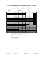
Jabiru 2200 Component Inspection and Assembly Procedure
7.4.3
Sub-Assembly C - Pistons, Cylinders and Cylinder Heads
Cylinder Head Clean Up
C1
1)
2)
3)
4)
5)
Clean oil off heads.
Dip heads in a cold dip solvent (i.e. Redik dkt Degreaser - Decarboniser Paint stripper) as per manufactures instructions to remove all carbon
deposits.
Note. The heads can be bead blasted, but care must be taken.
Wire buff valves.
Clean all other parts.
Cylinder Head Inspection and Repair
C2
1)
2)
3)
4)
5)
Page No: 42
Inspect cylinder head for flatness. If sealing surface show signs of leakage
it may need refacing. When refacing, remove only the minimum to clean
up.
Measure valve guide wear.
If wear is excessive remove guides. Measure valve guide bore in the head.
The new guide must have at least 0.05mm (0.002") interference on the
outside diameter.
Note - The standard guide has no dimples in top (P.N.4518064) In
(P.N. 4519064) Ex
0.05mm (0.002") has one dimple
0.05mm (0.004") has two dimples
0.05mm (0.006") has three dimples
Press guides back in.
Note - Oil hole must go up
Special Note Guides: Guides are installed at 7.05mm bore diameter.
Guides from 7.08mm can cause oil usage in the engine (max. valve stem to
guide clearance is 0.12mm).
Issue No: 4
Date: 240103
Issued By: PJA
5)
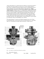
Mount head up and cut seats as per drawing
Note - When cutting seats cut enough to clean up but try to remove as little as possible.
This will give maximum number of overhauls on heads. The above diagram gives
general valve seat cut geometry. Changes have occurred to production engines.
S/N: 01 – 208 used above geometry. S/N: 209 –743 used wider contact seat area.
Engines 745 + used seat width cut from approved dwg. 4797004(I) and
4790004(E). Above valve diameters change S/N: 189 on.
6)
Page No: 43
Use ground and serviceable valves to check seat contact.
Issue No: 4
Date: 240103
Issued By: PJA
7)
8)
9)
Note - If machine has a vacuum tester, vacuum test valves.
Heads of valves must be above the level of the combustion chamber. If
they are below, the valve seats and valves must be replaced.
Measure valve stem for wear. Record in build sheet if within limits or
replace valves.
Grind valve seats. If margin is too small, replace valves.
Drawing 9444064
C3
1)
2)
Page No: 44
Clean heads and valves ready for assembly.
Measure valve springs. Replace if they are shorter than service limits.
40.0mm – 41.8mm (1.580" - 1.688")
Issue No: 4
Date: 240103
Issued By: PJA
3)
4)
Drawing 9443064
Inspect valve spring seats, valve spring retainers and valve collets. Replace
any that show signs of wear.
Lube valves well. Install valves, valve spring seats, springs, retainers and
collets.
Note: All engines have the same spring retainer on exhaust and inlet valve.
Drawing 94470641/2
Page No: 45
Issue No: 4
Date: 240103
Issued By: PJA
C4
Install Push Rod Tube O'Rings with a small amount of rubber grease.
Rocker Assembly
C5
1)
2)
3)
4)
5)
6)
7)
8)
9)
10)
11)
12)
Page No: 46
Disassemble and clean off all carbon.
Inspect rocker tip for wear. Replace any with excessive wear.
Measure bushes and record on build sheet.
If over service limits, replace.
Drawing 9449064
Clean off old Loctite from rocker bore.
Press in Bushes.
Note - The width of the bushes is critical for the correct amount of
end float. so they must be pushed right home.
- By putting the outer (wider flange) bushes to the left makes
a left bush and vice versa. Always keep rockers matched
i.e. left stays left and right stays right.
Put a small amount of Loctite 290 (wickin) on bushes to lock them on.
Ream bushes with an adjustable ream to dia 12.03mm - 12.05mm
(0.474" - 0.475").
Measure rocker shafts for wear and inspect for scratching, scuffing etc.
Record in Build Sheet.
Inspect rocker blocks.
Note - If the clamp capscrew comes loose it will let the shaft rock.
Any blocks like this must be replaced.
Assemble rocker block.
Actions 5 – 8 refer to earlier bushed rockers up to engine 118. Engines
from 189 onwards use either 12mm or 15mm wide GLASIER type bush.
These were pushed in to fit (friction fit, no compound used to lock). Bush
join goes to top of rocker.
Issue No: 4
Date: 240103
Issued By: PJA
13)
14)
Cylinders
C6
1)
2)
Drawing 9449064
Put capscrew through clamp hole and check rocker end float. Must be 0.1
to 0.4mm (0.004" to 0.010"). Face off outside bushes to adjust.
Clean up, oil well and reassemble.
Clean and visually inspect.
Mount cylinders in honing machine by base and hone with Sunnen mm
33-J85 Stone
Drawing 9436064
3)
Page No: 47
Measure and record in Build Sheet
Issue No: 4
Date: 240103
Issued By: PJA
4)
5)
6)
7)
Pistons
C7
1)
2)
3)
C8
1)
2)
3)
Bead blast cylinder outer to remove all old paint and rust.
Etch prime and paint with high temperature black paint.
Run 5/16 UNF Tap through head threads to remove all beads and to insure
that head bolts torque up fully.
Clean in kero then in hot soapy water to remove all honing oil etc.
Note: Once cleaned, oil up cylinders straight away. Store in a cool dry
place in a sealed container.
Clean oil out of pistons.
Dip Pistons in cold dip solvent (i.e. Redik DKT degreaser - decarboniser paint stripper) as per manufacturers instructions to remove all carbon.
Note: The head of the piston can be bead blasted, but never bead blast
the ring grooves, piston skirt and piston pin bores.
Use an old ring to clean carbon out of ring grooves but care must be taken
not to scratch grooves. Any scratching will cause Gas Leakage past the
rings. A piece of 2mm (0.080") perspex can also be used as it is kinder to
the pistons.
Clean thoroughly.
Visually inspect pistons for cracks or damage.
Measure pistons and record in build sheet.
Drawing 9434064
4)
(i)
(ii)
(iii)
(iv)
(v)
(vi)
(vii)
Page No: 48
Clean inhibitor off new rings.
Measure end gap of rings in the cylinder and record in build sheet.
Fit rings with dots up
Note: End of oil ring expanded must be butted together. Piston
rings orientated with joins opposite and not in thrust line.
Fit pistons in cylinders. Oil Ring should only just enter so piston
pin can be fitted later.
Note: Arrows on inside of pistons point in direction of rotation.
Oil Rings and pistons and bore well. Also notch on the
piston crown faces the Propeller Flange.
Fit front piston pin circlip.
Fit cylinder base O Ring.
Seal up in plastic bags ready for final assembly.
Issue No: 4
Date: 240103
Issued By: PJA
Jabiru 2200 Component Inspection and Assembly Procedure
7.4.4
Sub-Assembly D - Sump and Oil Pump
Sump
D1
1)
2)
D2
Remove induction O Rings.
D3
Inspect carburettor coupling replace if it is damaged or showing signs of
deterioration.
Note: It is very important that the carburettor and coupling are free of oil.
If there is any oil present at all, it is possible for the carburettor to
slip out of the coupling or if the clamp is not positioned to the
rubber edge facing the carby
D4
Fit new induction O Rings to Induction Pipes.
Oil Pump
D5
1)
2)
Clean sump and remove all gasket eliminator.
Inspect oil pick up.
Inspect oil pump inner and outer for damage to rotor surfaces.
Measure
rotor clearance.
Drawing 9440064
Housing to Outer Rotor clearance 0.07mm to 0.14mm (0.003" to 0.006")
Inner Rotor to Outer Rotor 0.07mm to 0.14mm (0.003" to 0.006")
3)
Page No: 49
Fit Inner Rotor into Outer Rotor. Using straight edge check end clearance.
End Clearance 0.03mm to 0.006mm (0.0015" to 0.003")
Issue No: 4
Date: 240103
Issued By: PJA
Drawing 9428064
Page No: 50
Issue No: 4
Date: 240103
Issued By: PJA
Jabiru 2200 Component Inspection and Assembly Procedure
7.4.5
Sub-Assembly E - Flywheel & Ignition Coils & Alternator & Alternator Operation
Flywheel Inspection
E1
Inspect ring gear for damaged teeth
E2
Use a spring scale and a prop cap screw as per drawing to test ignition magnet
strength. Pull off should be 1.5 to 2.5 kg (3.3 to 5.5 lbs)
Drawing 9437064
E3
Use spring scale and prop cap screw as in E2 to test alternator magnets. Pull off
should be 1.5 to 2.5 kg (3.3 to 5.5 lbs).
Page No: 51
Issue No: 4
Drawing 9438064
Date: 240103
Issued By: PJA
Ignition Coil Inspection
E4
1)
Using a multimeter measure the primary resistance (from the earth
terminal to the iron core). It should be 0.8 R to 1.0 R.
Drawing 9439064
2)
Measure the secondary resistance (from the high tension lead to the iron
core) it should be between 5.9 KR to 7.1 KR.
Drawing 9439064
Alternator Inspection
Page No: 52
Issue No: 4
Date: 240103
Issued By: PJA
E5
1)
Use multimeter to test resistance of windings. Resistance should be
0.5 to 1.1 R.
2)
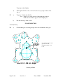
Use multi meter to test resistance to ground. Resistance should be infinite.
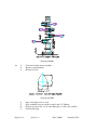
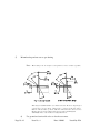
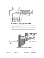
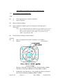
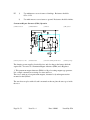
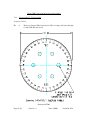
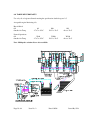
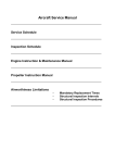
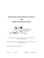
Permanent Magnet Alternator (PMA) Operation
(1) Master Switch
(3) Main Bus Bar
(5) Battery
(7) Regulator
(2)Voltage Reference Line
(4) Fusible Link
(6) Permanent Magent Alternator
(8) Charge Lamp
The charging system supplies electrical devices and also charges the battery while the
engine runs. It consists of a Permanent Magnet Alternator (PMA) and a Regulator.
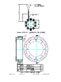
1. This permanent magnet alternator (PMA) is a 10 pole rotating magnet type generator.
It is a simple construction consisting of a stator and rotor.
The rotor is made up of ten permanent magnets, alternator body and magnet retainer
mounted on the flywheel.
The stator has ten poles with coils and is mounted on the rear plate the stator goes inside
the rotor.
Page No: 53
Issue No: 4
Date: 240103
Issued By: PJA
Page No: 54
Issue No: 4
Date: 240103
Issued By: PJA
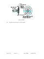
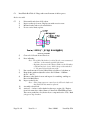
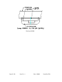
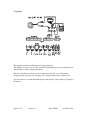
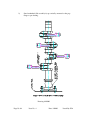
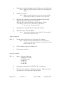
2. Regulator
The regulator performs rectification and voltage regulation.
The regulator converts A.C. into D.C. which flows through the power consuming circuits
and the battery, and also charges the battery.
If however, the battery voltage exceeds a certain level, the D.C. is cut off from the
charging circuit to prevent over charging. An isolating switch or fuse could be used.
For best results it is recommended that positive and negative of the regulator go directly to
the battery.
Page No: 55
Issue No: 4
Date: 240103
Issued By: PJA
Jabiru 2200 Component Inspection and Assembly
7.4.6
Sub-Assembly F - Gear Case
F1
Remove distributor shaft seals and rotor seal and discard.
F2
F3
Inspect Distributor shaft posts for signs of leaking.
Note: If there is no signs of leaking don't disassemble. But if it is leaking
disassemble and clean off old master gasket. Inspect surfaces and
reassemble.
Clean gear case distributor shaft and engine mount plate.
F4
Measure distributor shafts and record on build sheet.
F5
Measure distributor shaft posts and record in build sheet.
F6
Fit shafts into gearcase and using a straight edge and feeler gauge measure end
float. Record in build sheet.
F7
Visually inspect gears for wear.
F8
Fit seals to gear case. Use suitable seal lubricant.
F9
Lube shafts and fit to gear case.
F10
Fit rotors, rotors are glued to shafts.
F11
Visually inspect engine mount plate for
F12
Seal up and store for final assembly.
Page No: 56
Issue No: 4
1) Damaged Threads
2) Wear from distributor shafts.
Date: 240103
Issued By: PJA
Jabiru 2200 Component Inspection and Assembly
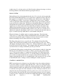
7.4.7
Sub-Assembly G - Fuel Pump and Carburettor and Carburettor Operation
Fuel Pump
The fuel pump on the 2200 engine is replaced as a complete unit at overhaul. It can be
inspected for faults by removing the top half.
Things to look for are: 1) Stuck or leaking valves
2) Torn diaphragm
3) Weak springs
4) Broken actuating lever.
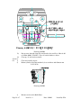
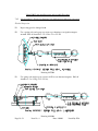
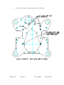
Carburettor Operation
The BING constant depression carburettor type 64-3 or 94/40 comprises a cross draught
butterfly-valve carburettor with variable choke tube, double-float system arranged
centrally below the carburettor venturi and a rotary-valve type starting carburettor. It
features a throttle slide which is suspended from a roller diaphragm and projects into the
venturi. It changes the smallest cross-section ("choke tube") of the venturi as a function of
the vacuum at this point.
Early throttle valve diameter is 36mm, later is 42mm
MOUNTING
The carburettor is secured to the engine using a 52mm diameter push-on connection which
takes a flexible connecting piece with clamps. On the intake side the carburettor is
provided with a socket having a diameter of 55mm and a length of 12mm for connecting
an air filter or intake silencer.
FUEL INTAKE CONTROL
The float (40) of the carburettor consists of two plastic float elements joined by a metal
hinge. The float is arranged centrally below the carburettor choke tube so that the
carburettor can be tilted very far in all directions without impairing operation. The object
of the float is to maintain the fuel level in the float chamber (44) constant. When the fuel
has reached a specified level in the float chamber, then the float (40) mounted on pin (41)
is lifted until the float needle (42) is pressed against the seat of the float needle valve, thus
preventing any further supply of fuel. When the engine draws in fuel from the carburettor,
the level in the float chamber (44) drops and so does the float. The float needle then
opens the valve again and allows fuel to flow in from the tank. The float needle valve
regulates the fuel supply in conjunction with the float but it does not act as a stop valve
when the engine is at a standstill. Minute foreign bodies may be deposited between valve
Page No: 57
Issue No: 4
Date: 240103
Issued By: PJA
seat and needle tip, thus preventing complete closure of the valve. When stopping the
engine, therefore, the fuel cock on the tank should always be closed. In addition the fuel
should be filtered before it reaches the carburettor. The filter should be selected so that
foreign bodies greater than 0.1mm are filtered out and the fuel supply is not impeded to
too great an extent.
The float needle (42) contains a spring-loaded plunger which contacts the float hinge.
This absorbs vibrations on the float (40). In addition the float needle (42) is connected to
the float hinge by the retaining spring (43) to prevent it from moving between float and
valve seat and thus reducing the fuel supply. Spring and retaining guide make a
considerable contribution towards keeping the fuel level in the float chamber constant.
When fitting a new float, the fuel level must be adjusted. When doing this care must be
taken to ensure that the fuel needle spring is not compressed by the float weight. It is
therefore advisable to put the carburettor in a horizontal position until the float just
contacts the float needle. In this position the point on the float hinge is set in such a way
that the float top edges are parallel to the top edge of the float chamber.
The float chamber (44) is secured to the carburettor housing by a spring yoke (45). A seal
(46) is provided between float chamber and carburettor housing. The space above the fuel
level is connected to atmosphere by two ducts. When these ducts are blocked, an air
cushion forms above the fuel. The fuel will not lift the float sufficiently to close the
needle valve and the carburettor overflows.
The float chamber (44) incorporates an overflow pipe to allow fuel to drain off if the
specified level in the float chamber is exceeded substantially due to a leaking needle
valve.
MAIN REGULATING SYSTEM WITH PRESSURE REGULATOR
The amount of mixture drawn in by the engine and thus its performance is determined by
the cross-sectional area in the choke tube which is opened by the throttle valve (23). The
throttle valve is secured to the valve shaft (24) by two screws (25). The end projecting
from the carburettor housing carries the throttle levers (27) + (28) which are secured by
the nut (3) and washer (29) to which the Bowden cable operating the throttle shaft is
attached. The sealing ring (26) provides the seal between valve shaft and housing. The
retaining arm (31) attached to the carburettor housing by means of screws (32) and
washers (33) engages the notch in the valve shaft and thus prevents it from moving in
axial direction. The return spring (35) whose action opposes the Bowden cable is attached
between a bent-over tab at the lower end of the retaining arm and the throttle lever (28). If
the throttle valve (23) is opened while the engine is running, the increased air flow in the
choke tube results in a vacuum building up at the outlet of the needle jet (3) which draws
fuel from the float chamber through the jet system. At low speeds and in particular in the
case of four-stroke engines, this vacuum is not sufficient for an adequate fuel supply; it
must therefore be increased artificially by using a pressure regulator. For this purpose the
BING constant depression carburettor type 94 is provided with a plunger (13) operating in
conjunction with a diaphragm (16); which reduces the cross-sectional area or the needle
Page No: 58
Issue No: 4
Date: 240103
Issued By: PJA
jet outlet by virtue of its own weight or, in some applications with the additional pressure
from a spring (22), and thus increases air velocity and vacuum at this point.
The plunger (13) is located centrally in the cover (20) which is secured to the carburettor
housing by screws (21). The diaphragm (16) is connected to the plunger (13) by a
retaining ring (17) and four screws (18) and washers (19) each. The vacuum in the choke
tube acts on the top of the diaphragm and the plunger via a bore (U) in the plunger (13)
and attempts to lift the plunger against its own weight and spring (22). The considerably
lower vacuum between air filter and carburettor is applied to the underside of the
diaphragm via duct (V) as a reference pressure.
If the throttle valve (23) is opened when the plunger (13) is closed, then a vacuum will
build up in the small cross-section at the bottom of the plunger (13) which is sufficient to
provide a supply of fuel. The weight of the plunger (13) and the force of the spring (22)
are matched in such a way that this vacuum will be maintained with increasing speed until
the plunger has fully opened the carburettor cross-section. From this point onwards the
carburettor acts as a throttle valve carburettor with fixed choke tube. The vacuum
increases with increasing speed.
The space in the cover (20) above the plunger guide is vented through bore (D). Its
diameter is designed in such a way that it acts as a restrictor for air flowing in and out and
therefore acts as a vibration damper for the plunger.
On its way from the float chamber to the choke tube the fuel passes through the main jet
(1), the jet carrier (10) and the needle jet (3); as it leaves the needle jet it is pre-mixed with
air which is brought in from the air filter via an air duct (Z) and the atomiser (2) in an
annular flow around the needle jet. This air flow assists the atomising process to form
minute fuel droplets and thus favourably affects the fuel distribution in the intake
manifold and combustion in the engine.
The conical section of the jet needle (4) which is secured to the plunger (13) with the
retaining spring (14) and the serrated washer (15) engages into the needle jet (3).
Depending on the dimension of the flat cone at the end of the jet needle, the annular gap
between jet needle and needle jet is enlarged or decreased and thus the fuel supply is
throttled to a lesser or greater extent. The jet needle (4) can be located in the plunger (13)
in four different positions which, similarly to the jet needle cone, affect the amount of fuel
drawn in. For example "needle position 3" means that the jet needle has been suspended
from the retaining spring (14) with the third notch from the top. To achieve the height
adjustment the jet needle is turned through 90o and pushed up or down, the retaining
spring engaging the next notch in the jet needle. If the needle is suspended higher up, this
will result in a richer mixture and vice versa.
In short the main regulating system is set using main jets and needle jets of various
diameters and also jet needles, plungers and pistons of various types.
Between main jet (1) and nozzle stock (10) a washer (12) is provided which, together with
the float chamber, forms an annular gap. In particularly severe operating conditions this
ensures that the fuel is not spun away from the main jet.
Page No: 59
Issue No: 4
Date: 240103
Issued By: PJA
A rubber ring (11) seals the nozzle stock (10 off from the carburettor housing to avoid any
fuel being drawn in via the thread and thus bypassing the main jet.
IDLING SYSTEM
During idling and low-load running the throttle valve (23) is closed to such an extent that
the air flow underneath the plunger (13) no longer forms a sufficient vacuum. The fuel is
then supplied via an auxiliary system, the idling system, which consists of the idling jet
(5), the idling air jet (LLD) - no spare part - and the mixture control screw (7) which is
sealed off against the carburettor housing by the rubber ring (9) and secured by spring (8)
to prevent it from becoming slack. The fuel passes through the idling jet (5) whose bore
will determine the amount of fuel. Behind the jet bore the fuel mixes with air which is
supplied via cross ducts in the jet throat from the idling air channel, the amount of air
admitted being determined by the size of the idling air jet at the inlet of this duct. This
initial mixture then flows through the idling outlet bore (LA), the cross-sectional area of
which can be adjusted by the mixture control screw (7); it then reaches the choke tube via
bypass or transition passages (BP) where it is mixed further with pure air.
Idling should always be with the engine at operating temperature. First the mixture
control screw (7) is turned fully clockwise and then backed off by the number of turns
specified for the particular engine. Turning in clockwise direction results in a leaner
mixture and turning in anti-clockwise direction in a richer mixture.
The idling setting quoted serves as a guide only. The optimum will generally differ
slightly. First select the desired idling speed by using the idling stop screw (34). When
subsequently adjusting the mixture control screw - starting from the basic setting - a speed
drop will be noticed in both directions. The optimum setting will generally be found halfway between the two settings at which this speed drop was noticed.
To facilitate the idling setting on engines having several carburettors where it is important
that they are evenly adjusted, it is possible to connect a pressure gauge (in the simplest
case a "U-tube pressure gauge") to a nipple below the throttle valve shaft bearing point
which is normally closed off by screw (39). To select the idling speed, the idling screw
(34) is in this case adjusted until the same vacuum is indicated for all carburettors. By
slightly opening the throttle valve via a turning handle or the accelerator it is also possible
to adjust Bowden cables or linkages evenly by making this vacuum comparison.
STARTING CARBURETTOR
BING constant depression carburettor is provided with a rotary valve starting carburettor
as an aid for staring a cold engine using a Bowden cable. A disc (47) resting against the
carburettor housing is turned via a shaft in the starting carburettor housing (48) so that the
starting carburettor chamber into which air enters from the air filter side of the carburettor
is connected to the engine side of the carburettor via a duct. The airport in the disc (47) is
shaped in such a way that depending on the disc position, more or less air is drawn in. At
the same time the disc opens the fuel system of the starting carburettor via bores matched
to the disc position. The fuel flows from the float chamber through the starting jet into the
Page No: 60
Issue No: 4
Date: 240103
Issued By: PJA
vented starting chamber also contained in the float chamber (44) and from there through a
riser where it is pre-mixed with air via transverse bores, into the starting carburettor.
There it forms a particularly rich mixture with the air drawn in, and this mixture bypasses
the main carburettor to flow into the intake manifold of the engine direct. During
starting the throttle valve has to be closed to make sufficient vacuum available for the
starting carburettor. When the engine is at a standstill and also during normal operation
the fuel level in the float chamber compartment incorporating the riser will be the same as
in the rest of the float chamber. When starting with opened-up starting carburettor, the
fuel will initially be drawn in from this compartment which forms a very rich mixture.
The fuel supplied subsequently will only be the amount allowed through by the starting
jet. This ensures that, once the engine has started, it is not supplied with an excessively
rich mixture and stalled. The starting carburettor is therefore matched to any given engine
by modifying the starting jet and matching the space behind it.
The starting carburettor is secured to the carburettor housing by four screws (51) and
protected against ingress of dirt and water by the seal (50) between the two. The starting
shaft is also sealed against the starting carburettor housing by a rubber ring (49).
Carburettor Overhaul
Note: As a guide to overhaul read carburettor operation.
G1
Disassemble carburettor
Page No: 61
Issue No: 4
Date: 240103
Issued By: PJA
G2
Using over haul kit replace all components
G3
Record jet size
G4
Record needle position
G5
Reassemble carburettor
Page No: 62
Issue No: 4
Date: 240103
Issued By: PJA
Jabiru 2200 Component Inspection and Assembly
7.4.8
Sub-Assembly H - Final Assembly
Crankcase Joining
H1
a)
Photocopy Degree Wheel (increase by 226% to bring to full size) then glue
to stiff cardboard and cut out.
Drawing 9427063
Page No: 63
Issue No: 4
Date: 240103
Issued By: PJA
b)
Stand crankshaft (Sub assembly A) up vertically, mounted on the prop
flange as per drawing.
Drawing 9429063
Page No: 64
Issue No: 4
Date: 240103
Issued By: PJA
H2
H3
H4
c)
a)
Apply Loctite 515 to left side of the crankcase.
Fit cam shaft to left side
b)
Inspect
c)
You will need 1)
2)
3)
4)
5)
6)
7)
8)
9)
a)
Stage Inspection
b)
Oil all bearing, crank and camshaft
c)
Fit halves over crankshaft assembly and squeeze up by hand.
a)
Using spacers and plain nuts on rear studs and belleville washers and
MS21042L6 nuts on the front studs pull the crankcase together (but don't
do up tight)
b)
Remove rear nuts
1)
2)
3)
4)
5)
6)
7)
Bearing shell in position
Loctite on all areas
O Rings in
Piston/Cylinder Assembly complete
Thrust washers in position
Dowels in
Lifter are in with moly grease on faces
An extra person
4 7/16 Ring Open End spanners
2 9/16 Ring Open End spanners
2 3/8 Plain grade 5 nuts
2 3/8 Belleville Washers
18 through stud nuts (MS21042L6)
6 through studs
Torque wench
7/16 x 3/8 drive 2" extension
(snap on no fres 14)
10)
Long Nose Pliers
Note: An extra person makes it easier to bolt up and also can cross check
work.
H5
Put all through studs in
H6
a)
Fit piston/cylinder assemblies to No. 1 & 2 conrods
b)
Fit circlips cross check circlips for correct fit. Push cylinders home.
c)
Put cylinder base nuts (MS21042L6) on. Using 2 7/16 ring spanners do
up each side together.
If one nut goes on more than 3 turns put the 3/8 plain nut on top of it and
use a 9/16 ring spanner to hold the nut, locking up the stud.
Page No: 65
Issue No: 4
Date: 240103
Issued By: PJA
Torque up by hand lightly.
H7
d)
Turn engine 1/2 turn so No. 3 & 4 conrod are out. repeat procedure on No.
3 & 4.
a)
Torque to 15 ft lbs then 30 ft lbs.
Note: Keep an eye on the amount of thread through each nut.
Both sides should have approx 2 turns hanging out.
b)
Put anti sabotarge. Paint on nuts.
Camshaft Timing
H8
a)
STAGE INSPECTION
Fit crankshaft gear as drawing and put one bolt in crankshaft to hold gear.
Note: Timing marks on cam
gear are on 2 teeth.
Crankgear marked on one
tooth.
Drawing 9432064
Page No: 66
Issue No: 4
Date: 240103
Issued By: PJA
b)
Mount a dial indicator on cylinder with the plunger on the center of the
piston.
c)
Zero the indicator at T.D.C.
d)
Fix a wire pointer of the oil seal bolt hole and roughly set to T.D.C.
e)
Turn 1/4 turn backwards then forward until the piston is 2mm from T.D.C.
Note degrees.
Turn past T.D.C. to 2mm down from T.D.C. Note degrees.
Add two together then divide by 2 and set pointer at this (with piston down
2mm)
Note: The crank is mounted to turn the engine in direction of
rotation turn crankcase anti clockwise viewed from rear.
f)
Repeat again to check.
Note: It is important to find T.D.C. accurately as it is the datum
for setting the cam timing and ignition timing.
g)
Set dial indicator up to measure lift on No. 1 exhaust. Set to 0 on max lift.
h)
Turn 1/4 turn backwards then turn until 0.5mm (0.020") from peak note
degrees continue turning until 0.5mm (0.020") after peak.
Note: Always turn in direction of rotation to eliminate back lash in
gears.
i)
Calculate total degrees and divide by 2 to find peak. Peak should be 70o72o after B.D.C.
j)
The cam shaft gear has 22 teeth and 6 bolt holes, so if it needs adjusting.
Move the gear around and re check. Record final measurement in build
sheet.
Head Fitting
H9
a)
Insure * All O Rings are place and greased
* Have all head bolts
* Head Gaskets
* Push rod tubes
* Push Rods
* Rocker Blocks
* Loctite 515
* Loctite 626
b)
Fit heads by hand.
Page No: 67
Issue No: 4
Date: 240103
Issued By: PJA
c)
Push the push rod tube through the head and all the way home. Fit circlips.
Note: Make sure outside of tubes are smooth or it will damage the
O Rings.
d)
Oil Push rods and fit.
Note: Make sure ball end of push rod is in the socket of the lifter.
It also helps if the lifter is on the base circle of the lobe.
e)
Put loctite 515 on the base of the rocker block and fit long bolt torque
lightly by hand (heads with separate rocker block).
Put loctite 262 on rocker block cap screw and torque to 16 ft lbs.
Note: Engine serial no: 225 on do not have rocker blocks.
¼” unc cap screw is torqued to 8 ft lb
f)
Torque heads to 16 nm then 32 nm (12 ft lbs then 24 ft lbs).
g)
Adjust all valves to 0.25 mm (0.010").
Note: Valves must be adjusted with the lifter 180o to the peak lift
to ensure it is on the base circle.
Sump and Induction
H10
a)
Fit sump using loctite 515 on faces and loctite 242 on threads.
Note: Because the engine mount plate goes on the sump and
crankcase it is important to make sure the sump is level with
the rear crank case face.
b)
Fit 3 & 4 induction pipe to heads then 1 & 2
c)
Fit lower pipes and hoses
Gear Case and Rear
H11
a)
Insure *
*
*
*
*
*
b)
Turn engine around until it is 25o B.T.D.C. No. 1 compression
c)
Put loctite 515 on crankcase. Fit engine mount plate. Make sure 2 inside
cap screws are in. Use loctite 242 on all cap screws.
Page No: 68
Gear case is fitted up
Backing plate is ready
All bolts are ready
Loctite 515
Loctite 242
Loctite 262
Issue No: 4
Date: 240103
Issued By: PJA
d)
Put loctite on gear case and point rotors to No: 1 Position.
Note: It is recommended that rotors are attached with small amount of silastic or 5 minute
araldite/flox mix. This will prevent them from loosening. This still allows rotors to be
removed when necessary.
Page No: 69
Issue No: 4
Date: 240103
Issued By: PJA
Drawing 9431064
Note: When gear case goes on
1)
Make sure No. 1 is 25o before T.D.C. compression.
Both valves should be seated.
2)
The rotors point to the No. 1 position on the rotor
caps.
Fit cap screws with loctite 242 and torque.
H12
a)
Fit flywheel with the magnets horizontal (they then should line up with the
coils).
Note: The small hole in the flywheel will line up with the hole in
the crankcase. (It may not line up with the hole in the gear
if it has been moved for cam timing.) Put loctite 262 on new
flywheel cap screws and torque to 20 nm (15 ft lbs).
b)
c)
Fit coil mount posts and alternator mount.
Fit coils and set gap to 0.25mm (0.010")
Page No: 70
Issue No: 4
Date: 240103
Issued By: PJA
Note: A strip of 0.25mm (0.010") card is best because it is not a
magnet. Coil direction lead follows prop rotation.
H13
Fit Carburettor assembly
Note: It is very important to make sure hose clamp is at the outside end of
coupling, the coupling and carby are free of oil and the carburettor
goes fully into coupling, clamp is of 10mm wide stainless type.
H14
Fit Fuel Pump Assembly
Note: Use loctite 242 on cap screws. Use molybdenum disulphide grease
on push rod.
Oil Pump
H15
H16
a)
Put loctite 515 on back face of oil pump backing plate and fit.
b)
Fit woodruff key
c)
Fit inner gear to camshaft.
d)
Fit outer gear to housing and fill with oil.
e)
Fit O Ring
f)
Fit Oil pump on. Use loctite 242 on cap screws.
Note: Before torquing up, rotate engine carefully to ensure oil
pump is not binding. If oil pump binds it can sheer the end
of camshaft.
Fit exhaust system. Use a little anti seize on cap screws and shake proof washers.
Front Seal & Flange
H17
a)
Remove from vertical stand and mount on engine mount stand.
b)
Remove prop flange.
c)
Clean off oil from sealing surfaces.
d)
Use loctite 515 on crankshaft seal carrier to crankface and loctite on cap
screws. Put a little grease on seal. Install seal.
e)
Prime crankshaft and new prop flange bolts with loctite primer. Using
loctite 262 fit flange and torque to 40 nm (30 ft lbs).
e)
Wire flange,
Page No: 71
Issue No: 4
Date: 240103
Issued By: PJA
CAUTION if for any reason prop flange or prop has been damaged rear flywheel
capscrews should be replaced.
7.4.9
Engine Run In
The Jabiru engine is run in on a DYNOMOMETER and cooled with fan driven air. In
the absence of a DYNO controlled run, engines can be run in in the airframe. Very large
air ducts must be constructed to get adequate airflow for cooling in the static situation.
The flying air ducts must not be used for this purpose. Extreme care must be taken with
the cylinder head temps if run in is done in the airframe. Engine run in procedure allows
progressive build up of the B.M.E.P. (break mean effective pressure) in the cylinders
while carefully limiting the heat build up. In essence short amounts of hard work
increasing in intensity while limiting the heat build up is the format. This can be seen in
detail after the engine build sheets. All engines are run in before delivery including
overhauled engines as well. When delivered they are ready for flight.
Run Procedure to be used only if engine has not been run-in.
1)
Mount Engine on test rig (See engine installation)
2)
Fill with non detergent oil.
3)
Remove spark plugs and wind over until oil pressure is reached.
4)
Fit plugs and cooling ducts.
5)
Run in.
Follow run in program.
6)
Cool down (at least 12 hours)
7)
Retorque heads
8)
Adjust valves
9)
Rerun
10)
Check leak down
Note: There is a run in program and run in checklist to fill out.
Page No: 72
Issue No: 4
Date: 240103
Issued By: PJA
7.5
Engine Installation
Operation
1)
Fit engine to engine mount
2)
Torque engine mount bolts up
7/16 Tube Socket
7/16 Ring Open End
Spanner
3)
Fit muffler (if not already fitted) and fit carburettor
3/16 Ball End Allen
Key
Tools
heat muff and hose.
4)
Connect left and right ignition coils leads
5)
Connect Tacho sender
6)
Connect exhaust gas temp (if fitted)
7)
Connect cylinder head sender
18mm Spark Plug
socket
8)
Connect hourmeter
Screw Driver
9)
Connect oil temp gauge sender
10)
Connect oil pressure gauge sender
11)
Connect starter
7/16 Ring Open End
Spanner
12)
Connect Battery
10mm Ring Open End
Spanner
13)
Connect fuel line
Screw Driver
14)
Connect Oil Breather
Screw Driver
15)
Connect Choke Cable
Long Nose Pliers
16)
Connect Throttle Cable
Long Nose Pliers
17)
Connect Air Inlet
Screw Driver
18)
Fit Propeller and spinner
7/16 Ring Open End
Spanner
Page No: 73
Issue No: 4
Date: 240103
Issued By: PJA
Phillips Screw Driver
3/16 Allen Key
19)
Fit Cooling Ducts
20)
Prime Fuel system with electric pump and inspect
for leaks
21)
Check for oil. Fill if needed.
22)
Wind over to get oil pressure
23)
Start and inspect for leaks
24)
Test Fly
Note: First flight is a test flight so fly conservatively
25)
Remove Cowls and inspect for anything loose, rubbing or leaking.
26)
After 5, 10 and possibly 15 hours retorque heads, adjust valves and inspect engine
installation. Heads torqued to 24 (22) ft. lb. and valve clearance 0.010”.
27)
After 25 hours retorque heads, adjust valves and inspect engine installation.
Change oil and filter. Cut filter open and inspect. Check engine leak down.
28)
If oil consumption is stable fill with W100 (W80 in cold conditions and W120 in
very hot conditions). If it is still using oil remain on run in oil.
7.6
Prop Strike Inspection
2.3L oil (2.43 US
quarts)
After ground contact of a wooden propeller, check the crankshaft flange for run-out at the
front seal surface. If run-out is evident, the engine will have to be stripped and crankshaft
checked for cracks.
If an engine stoppage due to force is not recorded in the logbook and not advised to Jabiru,
the liability for all subsequent and consequential damage will remain with the owner.
This applies to both prior to and after engine overhaul.
7.7
Build Sheets and Run In Programme
Included with the build sheets are
* Pre Run Check List
* Run In Programme
* Post Run Checklist
Photocopy all documents and use photocopies to fill in. When complete, fax to Jabiru
Aircraft so all documents can be kept up to date. This helps us provide a better service to
our customers if we know what our engine is in and what has been done to it.
Fax Number Within Australia
Outside Australia
Page No: 74
Issue No: 4
07 4155 2669
+ 61 7 4155 2669
Date: 240103
Issued By: PJA
Jabiru Aircraft Pty Ltd
WARNING
This engine has been run in and is ready for flight.
DO NOT GROUND RUN THIS ENGINE
This engine has been inhibited and the oil system drained. Before first start of new engine, remove 1 spark
plug from each head. Add the required run-in oil to sump (2.3 litres), engine must have oil cooler fitted.
Press starter to obtain oil pressure and to throw out excess inhibiting oil in cylinders. Replace plugs.
NOTE: ALL plastic bungs must be removed
At each 5 hours for first 15 hours check tappet clearances (0.010" cold) and cylinder head bolt torque (24
ft.lbs/32nm).
Note: New style heads have a 1/8 NPT plug to be unscrewed to uncover head bolt No. 5. After torquing
reset plug.
¬ For the first 25 hours of operation, add 2 litres of Shell 100 oil. After 25 hours drain oil, retorque
cylinder head bolts to 24 ft lbs and check valve clearances (inlet and exhaust 0.010" cold).
¬ Use 2 litres of W100 oil for normal operation or W80 oil for cold weather operation.
¬ Shell also manufacture a multigrade oil Aeroshell 15W50 which is particularly suited for operations in
¬
¬
cold climates.
UNDER NO CIRCUMSTANCES USE AUTOMOTIVE OIL IN THIS ENGINE.
Use only oils which are designed for Air Cooled Aero Engines.
Some brands of automotive oils have been shown to cause very rapid cylinder wear. This will not be
covered under warranty.
Operate engine only on AVGAS 100LL or highest octane available MOGAS above 95 octane
containing lead. Failure to do so could result in engine damage and void warranty.
*USE OF OIL/FUEL ADDITIVES VOID WARRANTY
Page No: 75
Issue No: 4
Date: 240103
Issued By: PJA
Jabiru 2200 – Component Assembly Procedure
Subassembly A – Crankshaft, Propeller Mount Flange and Conrods
No.
A1
A2
A3
A4
A5
A6
A7
Stage
1
A8
Details
Inspect for Burrs, Oil Holes,
Chamfers; Clean Crankshaft,
Conrods and Propeller Mount
Plate
Inspect Oil Holes and Insert
Welch Plugs
Measure Crankshaft (refer to
Goods Inwards Inspection
Sheet)
Inspect and Measure Propeller
Mount Flange
Inspect and Measure Conrods
(refer to Goods Inwards
Inspection Sheet)
Mount Propeller Mount Flange
to crankshaft Torque to 30ft.lbs/
Lockwire
Fit the Conrods to the
Crankshaft; Use Loctite 620 on
the bolts and torque to 18ft.lbs
Stage Inspection of Assembly –
Conrods/Crankshaft
Sign
Sign
Date
I hereby certify that the subassembly has been completed using the approved procedures
and data; and is fit for installation.
Signed: _______________
Date: ____________
For Jabiru Aircraft Pty Ltd
Certificate of Approval #3501
Notes:
Page No: 76
Issue No: 4
Date: 240103
Issued By: PJA
C om ponentR egister and Parts Inspection R ecord
Subassembly A – Crankshaft, Propeller Mount Flange and Conrods
Batch ____________
Description
Crankshaft
Propeller Mount Flange
Part No
Batch
Item
Serial No ____________
Mains
1
4644082
4525064
Date ____________
Details
2
3
4
5
6
Big End
1
B/E Dia
Conrod
1
2
3
4
Conrod SHCS
5/16 x 1” UNF
Bearings ACL
4651183
4651183
4651183
4651183
4B8290
I hereby certify that the above listed parts conform with the dimensions, have been engraved, and
installed as recorded.
Signed ____________
Date ____________
For Jabiru Aircraft Pty Ltd
Certificate of Approval #3501
Page No: 77
Issue No: 2
Date:130598
Issued By: PJA
2
3
4
Jabiru 2200 – Component Assembly Procedure
Subassembly B – Crankcase and Camshaft Assembly
No.
B1
B2
B3
B4
B5
B6
B7
B8
B9
B10
B11
B12
Details
Inspect case, deburr, clean, check oil holes
Fit inner stud “O” rings
Fit all studs
Fit outer oil suction and conrod welch plugs
Fit oil relief valve, oil pressure sender and
pressure switch
Fit bearing shells (12)
Assemble and torque to 30 ft.lbs
Measure main tunnel and camshaft bearings
Measure Cam Follower Bores
Fit Lifters
Check Camshaft End Float
Check Crankshaft End Float
Sign
Date
I hereby certify that the subassembly has been completed using the approved procedures
and data; and is fit for installation.
Signed: _______________
Date: ____________
For Jabiru Aircraft Pty Ltd
Certificate of Approval #3501
Notes:
Page No: 78
Issue No: 2
Date:130598
Issued By: PJA
C om ponentR egister and Parts Inspection R ecord
Subassembly B – Crankcase and Camshaft Assy
Batch ____________
Description
Crankcase LS
Crankcase RS
Camshaft
Studs – Long Barrel
Part No
4308052
4309052
4279042
4291044
Studs – Short Barrel
Studs – Front
Outer Gear
Inner Gear
Crankshaft Gear
Main Bearings
4292044
4293044
4333054
4066123
4643084
5M1869
Serial No. ____________
Batch
Date ____________
Item
Details
1
2
3
Cam
1
2
3
Cam Followers
LHS
RHS
Signed ____________
Date ____________
For Jabiru Aircraft Pty Ltd
Certificate of Approval #3501
Issue No: 2
5
6
Cam
Tunnel
I hereby certify that the above listed parts conform with the dimensions, have been engraved, and
installed as recorded.
Page No: 79
4
Date:130598
Issued By: PJA
4
5
Jabiru 2200 – Component Assembly Procedure
Subassembly C – Pistons, Cylinders and Cylinder Heads
No.
C1
C2
C3
C4
C5
C6
C7
C8
C9
C10
Details
Clean and deburr all parts
Record all measurements
Install pushrod tube “O” Rings
Check valve seats, fit spring retainers, install
valves
Fit intake pipes to heads
Complete rocker shafts and rocker assemblies
Fit cylinder base “O” rings
Fit front circlip
Check ring end gaps, fit rings to pistons
Install piston assembly to cylinder just clear of
the oil ring
Sign
Date
I hereby certify that the subassembly has been completed using the approved procedures
and data; and is fit for installation.
Signed: _______________
Date: ____________
For Jabiru Aircraft Pty Ltd
Certificate of Approval #3501
Notes:
Page No: 80
Issue No: 2
Date:130598
Issued By: PJA
C om ponentR egister and Parts Inspection R ecord
Subassembly C – Pistons, Cylinders and Cylinder Heads
Batch ____________
Description
Serial No. ____________
Part No
Head 1
2
3
4
4577062
457806N
4577062
457806N
Cylinder 1
2
3
4
4554062
4554062
4554062
4554062
Piston 1
2
3
4
4685083
4685083
4685083
4685083
Rockers LH
RH
Gudgeon Pin
4647084
464808N
4299054
Batch
Date ____________
Item
Details
Inlet
Guides
Outlet
Bore
Length
Dia
Ring Gap
Top
Bottom
I hereby certify that the above listed parts conform with the dimensions,
have been engraved, and installed as recorded.
Signed ____________
Date ____________
For Jabiru Aircraft Pty Ltd
Certificate of Approval #3501
Page No: 81
Issue No: 2
Date:130598
Issued By: PJA
Jabiru 2200 – Component Assembly Procedure
Subassembly D - Sump
No.
D1
D2
Details
Deburr and wash sump, inspect for defects
Fit oil temperature sender
Sign
Date
I hereby certify that the subassembly has been completed using the approved procedures
and data; and is fit for installation.
Signed: _______________
Date: ____________
For Jabiru Aircraft Pty Ltd
Certificate of Approval #3501
Notes:
Page No: 82
Issue No: 2
Date:130598
Issued By: PJA
C om ponentR egister and Parts Inspection R ecord
Subassembly D – Sump
Batch ____________
Description
Sump
Part No
4630072
Serial No. ____________
Batch
Date ____________
Item
Details
I hereby certify that the above listed parts conform with the dimensions, have
been engraved, and installed as recorded.
Signed ____________ Date ____________
Page No: 83
Issue No: 2
Date:130598
Issued By: PJA
Jabiru 2200 – Component Assembly Procedure
Subassembly E – Flywheel and Ignition Coils
No.
E1
E2
E3
E4
E5
Details
Sign
Deburr and Clean
Fit magnets using silastic
Using loctite 620 fit the ring gear
Fit the alternator rotor
Fit the plugs to the ignition coils
Date
I hereby certify that the subassembly has been completed using the approved procedures
and data; and is fit for installation.
Signed: _______________
Date: ____________
For Jabiru Aircraft Pty Ltd
Certificate of Approval #3501
Notes:
Page No: 84
Issue No: 2
Date:130598
Issued By: PJA
C om ponentR egister and Parts Inspection R ecord
Subassembly E – Flywheel Assy
Batch ____________
Description
Flywheel
Ring Gear
Coil 1
2
Serial No. ____________
Part No
4645183
4066423
PI10522N
PI10522N
Batch
Date ____________
Item
Details
I hereby certify that the above listed parts conform with the dimensions,
have been engraved, and installed as recorded.
Signed ____________
Date ____________
For Jabiru Aircraft Pty Ltd
Certificate of Approval #3501
Page No: 85
Issue No: 2
Date:130598
Issued By: PJA
Jabiru 2200 – Component Assembly Procedure
Subassembly F – Gear Case
No.
F1
F2
F3
F4
F5
F6
F7
Stage 2
F8
Details
Deburr, clean and inspect all of the gears
Measure the shaft post internal diameters and the
distributor shaft diameters
Using loctite 515 fit the shaft posts to the gear
housing
Fit the distributor shaft seals and rear crankshaft
seal
Fit shafts to gears with 24 hour araldite
Fit the distributor shafts and gears to the gear
housing
Check end clearance of distributor shaft to case
flange
Stage Inspection of Assembly
Sign
Sign
Date
I hereby certify that the subassembly has been completed using the approved procedures
and data; and is fit for installation.
Signed: _______________
Date: ____________
For Jabiru Aircraft Pty Ltd
Certificate of Approval #3501
Notes:
Page No: 86
Issue No: 2
Date:130598
Issued By: PJA
C om ponentR egister and Parts Inspection R ecord
Subassembly F – Gear Case
Batch ____________
Serial No. ____________
Description
Part No
Distributor Mount Spacer 1
2
Distributor Drive Shaft 1
2
4632074
4632074
4332154
4332154
Gear Housing
Distributor Gear 1
2
4631073
4333054
4333054
Date ____________
Batch
Item
Details
Dia
I hereby certify that the above listed parts conform with the dimensions, have been engraved, and installed as
recorded.
Signed ____________
Date ____________
For Jabiru Aircraft Pty Ltd
Certificate of Approval #3501
Page No: 87
Issue No: 2
Date:130598
Issued By: PJA
Jabiru 2200 – Component Assembly Procedure
Subassembly G – Fuel Pump and Carburettor
No.
G1
G2
G3
G4
G5
G6
G7
G8
G9
G10
Details
Fuel Pump – Disassembly
Drill hole in spacer and insert breather
Final assembly checked for correct flow
Drill and tap upper half for 90o elbow and fit
Clean and reassemble
Carburettor needle position
Fit fuel line
Remove bowl and check jet size
Reassembly bowl
Fuel pump and carby engraved
Sign
Date
I hereby certify that the subassembly has been completed using the approved procedures
and data; and is fit for installation.
Signed: _______________
Date: ____________
For Jabiru Aircraft Pty Ltd
Certificate of Approval #3501
Notes:
Page No: 88
Issue No: 2
Date:130598
Issued By: PJA
Jabiru 3300 – Component Assembly Procedure
Subassembly H – Final Assembly
No.
H1
H2
Stage 3
H3
H4
H5
H6
H7
Stage 4
H8
H9
H10
H11
H12
H13
H14
H15
H16
H17
Details
Apply Loctite 515 to crankcase halves; lubricate
where necessary
Locate camshaft and crankshaft in crankcase
half
Stage Inspection Pre-joining Crankcase
Locate crankcase half over crankshaft and
camshaft
Tension front (2) and rear (2) studs
Fit oil pump assembly and front seal housing
Place all through bolts in crankcase
Fit piston and cylinder assemblies and check
circlips
Stage Inspection Piston/Circlips
Tension the cylinder base studs to 25 ft.lbs then
30 ft.lbs
Fit sump
Fit heads to cylinder torque 12 ft.lbs / 24 ft.lbs
Fit push rod and valve gear. Set gap to 0.10”
(0.25mm)
Check camshaft timing DEGREES
Fit fuel pump
Fit engine mount plate and gearbox housing
Fit flywheel alternator mount plate and ignition
coils and lead
Fit carby assembly
Fit exhaust system
Sign
Sign
Date
I hereby certify that the subassembly has been completed using the approved procedures
and data; and is fit for installation.
Signed: _______________
Date: ____________
For Jabiru Aircraft Pty Ltd
Certificate of Approval #3501
Notes:
Page No: 89
Issue No: 2
Date:130598
Issued By: PJA
Jabiru 2200A – Engine Test Schedule and Report
Engine s/n:
Date
Run-in
Temp
Wind
QNH
Humidity
Use Test Rig #1, Test Propeller #J1
Run into the Wind
Use Schedule Provided
Oil – Aeroshell 100
Test Results
Time
[min]
Start
Time
Oil Press
[kPa]
Oil Temp
[oC]
EGT
[oC]
CHT
#1
[oC]
CHT
#2
[oC]
CHT
#3
[oC]
CHT
#4
[oC]
0
30
45
60
90
105
120
Maximum RPM: ___________
Fuel Grade
Fuel Consumption
Avgas 100LL
L
I hereby certify that this engine has been tested in accordance with the approved
procedures and the Jabiru Aircraft Pty Ltd, Engines Division, Policy and Procedures
Manual and is fit for use.
Signed: _____________________________________
Page No: 90
Issue No: 2
Date: _________________
Date:130598
Issued By: PJA
Page No: 91
Issue No: 2
Date:130598
Issued By: PJA
Jabiru 2200A Aero Engine Ground Test Form
Date
Operator
Block
Seq
1
2
3
4
5
6
7
8
9
10
Start Time
Finish Time
Total
Time
11
Duration
5
5
5
5
5
5
5
15
5
60
5
Condition
Start and Idle
Take-Off Power
Cooling Run
Take-Off Power
Cooling Run
Take-Off Power
Cooling Run
75% Power
Cooling Run
Max Cont Power
Full/2000/Full
2500/2800/Full
2500/Full
Full/2500
Cooling Run
Record of Replenishments
Start Fuel Quantity
Fuel Added
Finish Fuel Quantity
Fuel Used During Block
Oil Added
RPM
1200
2500/Full
1200
Full
1500/2000
Full
2000
2800
2000
Rec.RPM
CHT 1
CHT 2
CHT 3
CHT 4
EGT
Oil Temp
Oil Press
Current
15 mins
30 mins
45 mins
60 mins
1200
Record of Maintenance or Adjustment:
Note: This chart gives a run time of 2 hours, engines now take approx. 50 minutes with this format but with shorter time intervals.
Page No: 92
Issue No: 2
Date:130598
Issued By: PJA
Run-In Checks
1.
Preliminary
Paperwork Complete
Sufficient Fuel
Correct Oil Level
All Connections Correct and Secure
2.
Start Run
Start Time
End Time
3.
Ignition Checks (repeat a couple of times for each side)
Left Side
1000/2000 rpm
Right Side
1000/2000 rpm
4.
Oil Leaks
Check Visually
5.
Instruments
Working and Correct Range
6.
Idle
Check idle screw (3/4 to 1 turn out)
7.
General Running
Smoothness
Noises
Manifold Sealing
8.
Oil Pressure and Temp
9.
Check Ignition light to Tacho Test Rig (Top End RPM)
10.
Check alternator Charging Voltage
_____________
_____________
Jabiru 2200A – Engine Post Run Procedure
SIGN
DATE
1. Heads retorqued 32 Nm (24 ft/lb). Valves Adjusted.
2. Check induction/exhaust bolts.
3. Any changes to be made.
4. Rerun, check for oil leaks and/or any modifications made (oil
pressure/leaks etc).
5. Check charging rate of alternator
Volts
6. Leak Down
80
80
80
80
Cyl 1
2
3
4
7. Check all paper work
8. Drain fuel/oil. Prepare for Shipment.
Page No: 93
Issue No: 2
Date:130598
Issued By: PJA
8.0 TABLE OF LUBRICANTS
Use only oils of registered brands meeting the specification detailed at para. 2.5.
Acceptable engine lubricating oils:
Run in Period
Oil
Outside Air Temp
80
-17oC to 25oC
100
15oC to 35oC
120
Above 35oC
Normal Operations
Oil
Outside Air Temp
W80
-17oC to 25oC
W100
15oC to 35oC
W120
Above 35oC
Note: Multigrade aviation oils are also available.
Page No: 94
Issue No: 2
Date:130598
Issued By: PJA
9.0 TORQUE SPECIFICATION FOR BOLTS & NUTS
Part
Nom. Dia (mm)
Spark Plugs
Cylinder Head Bolts
Crankcase Main Studs
Flywheel/Gear Bolts
Crankshaft Prop Flange Cap Screws
(Lockwire)
Oil Pump Cap Screws
Tappet Cover Cap Screws
Starter Motor Bolts
Carburettor Flange Bolts
Engine Mount Plate Bolts
12mm
5/16"
3/8"
1/4"
5/16”
3/8"
Propeller Bolts
Camshaft Gear Bolts (Lockwire)
5/16"
1/4"
5/16"
1/4"
1/4"
5/16"
1/4"
1/4"
1/4"
8mm
5/16”
1/4"
1/4"
Page No: 95
Date:130598
Gearbox Cover Bolts
Alternator & Coil Mount Bolts
Sump Cap Screws
Conrod Bolts
Issue No: 2
Torque
nm (ft.lbs)
11 (8)
34 (24)
40 (30)
20 (15)
24 (18)
40 (30)
20
7
20
11
14
16
14
14
14
14
24
9.5
11
(15)
(5)
(15)
(8)
(10)
(12)
(10)
(10)
(10)
(10)
(18)
(7)
(8)
Issued By: PJA
9.1
PRESCRIBED SEALANTS AND PRIMERS
Item
Main Bearing Studs
Conrod Bolts
Oil Pump Bolts
Sump Plate Bolts
Engine Mount Bolts
Gearbox Cover Bolts
Spark Plugs NGK D9EA*
Spark Plug Lubricant
Prop Mount
Flywheel
Camshaft
*
Sealant
Loctite 620
Loctite 620
Loctite 243
Loctite 243
Loctite 243
Loctite 243
Loctite “Nickel Anti -Seize”
Loctite 262
Loctite 262
Loctite 262
**
Tighten to finger tight to seat, then with plug socket turn an additional 1/2 turn
(8 ft/lbs) for a new plug.
All gasket areas use Loctite 'Gasket Eliminator' 515
9.2
NEW TOLERANCES
Page No: 96
Issue No: 2
Date:130598
Issued By: PJA
(All Dimensions are in Millimetres)
Crankshaft
Mains Journals
Big Ends Journals
Thrust Face
47.938 to 47.918
44.988 to 45.000
56.95 to 57.05
Crankcase
Main Bearings
Cam Bearings
Cam Thrust Face
Lifter Bores
Crank Thrust
47.975 to 48.005
20.00 to 20.020
14.95 to 15.10
9.000 to 9.050
56.65 to 56.85
Con Rods
Big Ends
Little Ends
Length Between
Bore Radius
45.028 to 45.070
23.005 to 23.015
74.485 to 74.498
Cam Shaft
Journals
Valve Lift
Fuel Pump Lift
Thrust Faces
19.96 to 19.97
6.900 to 7.100
2.45 to 2.55
15.18 to 15.25
Lifter
Stems
8.965 to 8.990
Pistons
Dia
Sidering Clearance
Pin Dia
Ring End Gap
97.50 to 97.53
0.01 to 0.02
22.990 to 23.000
0.400 to 1.000
Height 64.00 – 65.50
Cylinder Bore Dia
97.59 to 97.61
Length over flanges(A)106.450 to 106.500 (B) 106.950 – 107.00
Valve
Stem Dia Inlet
Stem Dia Exhaust
Guide I.D. Inlet
Guide I.D. Exhaust
Spring Free length
6.970 to 6.990
6.970 to 6.990
7.040 to 7.050
7.040 to 7.050
39.5 to 42
Distributor
Shaft dia
Shaft Post I.D.
Shaft End Float
14.940 to 14.970
15.00 to 15.03
1mm
Note: Early engine components can exhibit slight variations to these new tolerances but still be serviceable.
Page No: 97
Issue No: 2
Date:130598
Issued By: PJA
9.3
MAXIMUM ALLOWABLE CLEARANCES (Wear Limits)
(All Dimensions are in Millimetres)
Mains
Big Ends
Little Ends
Camshaft Journals
Crank End Float
Cam End Float
Lifter - Crankcase
Piston/Cylinder
Ring Side Clearance
Pin/Piston
Ring End Gap
Inlet Valve/Guide
Exhaust Valve/Guide
Min Spring Length
Distributor Shaft/Post
Distributor Shaft End Float
0.10
0.08
0.03
0.08
0.80
0.50
0.12
0.15
0.05
0.04
1.20
0.10
0.12
39.50
0.10
1.20
Cylinder Dia at Half stroke
Rocker Shaft/Rocker Arm
Oil Pump Gears
Bearing Clearances main
Big Ends
97.65
0.18
0.15
0.04 – 0.09 typical
0.04 – 0.06 typical
Note: Variation can occur, overall tolerances may be acceptable with advice from Jabiru
Aircraft Pty Ltd.
Page No: 98
Issue No: 2
Date:130598
Issued By: PJA
9.4
ELECTRICAL SYSTEMS SPECIFICATIONS
(All Dimensions are in Millimetres)
Ignition
Primary Resistance
Secondary Resistance
Coil Gap
Plug Gap
Ignition Harness Resistance
8.8R to 1.0R
5.9kR to 7.1kR
0.27
0.55
6.7kR per 300mm of length
Alternator
Coil Resistance
Coil Earth Resistance
A.C. Output
D.C. Output
0.5 to 1.1R
Infinite
30 VAC at 3000 RPM
14.2 VDA at 3000 RPM
Tacho
Coil Resistance
Gap
160 to 170R
0.4
Page No: 99
Issue No: 2
Date:130598
Issued By: PJA
10.0 TROUBLE SHOOTING
10.1 Engine Won't Start
12)
13)
14)
Possible Cause
Ignition OFF
Spark plug gap too large
Closed fuel tap or clogged filter
No fuel in tank
Wrongly connected high tension leads
Starting Speed too low, faulty or discharged
battery
Coil to Magnet gap too wide
High tension leads loose or damaged
Dampness in distributors
Spark plugs damp due to condensation
Plug face wet by fuel due to excessive actuation
of choke or overflow of carb
Float valve dirty or jammed
Jets in carb. clogged
Water in carb.
15)
16)
Insufficient compression
Engine damage
1)
2)
3)
4)
5)
6)
7)
8)
9)
10)
11)
Remedy
Switch ON
Adjust gap to 0.6-0.7mm or renew plugs
Open tap, renew filter, check fuel system for leaks
Refuel
Connect as shown on leads
Recharge or replace battery
Adjust to 0.4mm (0.016")
Check or renew connections
Thoroughly dry internally
Thoroughly dry both inside and outside of plugs
Dry spark plugs, trace possible faults in fuel system
or over flow of carb.
Clean or renew float valve
Clean jets
Drain & clean carb.,fuel line & filter. Water drain
fuel tank
Trace pressure loss & repair if necessary
Inspect oil strainer filter & oil filter for metallic
particles. If present, an engine overhaul may be
necessary.
Possible Cause
Remedy
1)
Choke activated
Close choke
2)
Float valve dirty, jammed or worn
Clean or renew float valve
3)
Intake manifold leak
Tighten all connections, renew faulty items
10.3 Engine Runs Erratically or Misfires Occasionally
1)
Possible Cause
Spark plug failure
2)
3)
4)
Faulty HT leads
Faulty ignition unit
Clogged fuel filter
Page No: 100
Remedy
Check plugs, clean inside & outside, adjust electrode
gap. If necessary, renew plugs
Dry damp leads, renew damaged leads
Renew ignition unit
Renew fuel filter
Issue No: 2
Date:130598
Issued By: PJA
10.4 Engine Runs Too Hot - Oil Temperature Above 110oC (230oF)
1)
2)
3)
4)
5)
Possible Cause
Too much oil in crankcase
Low oil level
Poor quality oil
Clogged oil filter
Excessive piston blow by
6)
Faulty bearings
7)
Faulty oil temperature gauge
Remedy
Check oil level & adjust if necessary
Check oil level & add oil if necessary
Oil change, use specified oil
Change filter
Common reason: worn or sticking piston rings,
complete engine overhaul necessary
If metallic particles are present in oil, complete
engine overhaul necessary
Exchange gauge
10.5 Unsatisfactory Power Output
1)
Possible Cause
Ignition failure
2)
3)
4)
5)
6)
Too much oil in crankcase
Insufficient fuel supply
Fuel not according to specifications
Incorrect throttle adjustment
Leak in air intake
7)
Carby diaphragm damage
Remedy
Check ignition circuits; check wiring and pick-ups;
replace ignition units.
Check oil level & adjust if necessary
Check fuel supply system
Re-fuel with specified fuel
Re-adjust throttle fitting
Check and tighten all connections, check carby
sockets.
renew diaphragm
Possible Cause
Remedy
1)
Insufficient oil in sump
Check oil level & replenish as necessary
2)
High oil temperature
Refer to Para. 10.4
3)
Faulty pressure gauge, sender or wiring
Check gauge, sender & wiring. Renew as necessary.
4)
Faulty crankshaft bearings
Engine overhaul
5)
Relief valve not sealing
Inspect, replace back after cleaning
10.7 Engine Keeps Running with Ignition Off
1)
2)
3)
Possible Cause
Idle speed too high
Faulty ignition switch
Overheated engine
10.8 Excessive Oil Consumption
Possible Cause
Page No: 101
Issue No: 2
Remedy
Adjust to proper idle speed (900 RPM)
Check switch & cables. Repair/replace as necessary
Conduct cooling run at 900 RPM
Remedy
Date:130598
Issued By: PJA
1)
2)
3)
4)
Worn, broken or wrongly fitted piston rings
Poor oil quality
Worn valve guides
Oil leaks
10.9 Knocking Under Load
Possible Cause
1) Octane rating of fuel too low
2) Spark plug fitted without sealing washer
3) Heavy carbon deposits
Repair/engine overhaul necessary
Oil change, use specified oil
Repair of cylinder head necessary
Seal leaks
Remedy
Use fuel with higher octane rating
Ensure one sealing washer on each plug
Remove cylinder heads & in combustion
chamber remove deposits. Determine oil
consumption.
10.10 Engine Hard to Start at Low Temperature
Possible Cause
1) Starting speed too low
2) High oil pressure
3) Low battery charge
Remedy
Preheat engine
At very low temperatures, a pressure
reading of up to around 500 kpa doesn't
necessarily indicate a malfunction
Fit fully charged battery
Note: Running this engine on low octane fuel will cause piston damage and in extreme
case failure of the top ring gland or holed piston due to detonation. Changing the
engine tuning to a leaner air fuel mix will cause piston damage.
Page No: 102
Issue No: 2
Date:130598
Issued By: PJA
11.0
JABIRU AIRCRAFT PTY LTD
NEW ENGINE WARRANTY
Jabiru Aircraft Pty Ltd, hereinafter JABIRU warrants that it will make good without charge, any defect which appears in
this engine.
Provided:
1.
the defect has been notified in writing to JABIRU:
(a)
before the engine has operated a total of 200 hours or,
(b)
within twelve (12) months of the date of delivery of the engine
to the first retail purchaser or from the date of independent Authority
authenticated first flight.
whichever comes first, and
2.
the engine has been delivered to a JABIRU Approved Service Centre or such other service facility as advised
by JABIRU, and
3.
the engine has been installed in an aircraft type in accordance with a JABIRU approved installation system,
and
4.
JABIRU has determined that the defect complained of is one of workmanship and is not caused by:
(a)
misuse or abuse of the engine such as by operation outside the approved Flight Manual, or
Maintenance and Operation Manual, etc, or by neglect
(b)
improper installation, including overheating.
(c)
operation of the engine after it is known to be defective
(d)
accident or deliberate act
(e)
atmospheric fallout or flood, hail, salt, wind, etc.
(f)
failure to carry out proper maintenance service
(g)
use of incorrect types and/or grades of fuel, oil or lubricants
(h)
alteration or modification of the engine by any party not
authorised in writing by JABIRU
(i)
the fitting of parts or accessories not marketed by JABIRU
(j)
any work carried out on the engine by someone other than an
Authorised JABIRU Service Centre or someone else authorised
by JABIRU in writing,
the use of any engine oil or fuel additive’s or oil stabiliser’s
(k)
B Y J AB I R U (or as ot her w i s e deci ded by J AB I R U ) MAK I NG GOOD T H E DE F E CT
B Y R E P AI R OR , AT T H E OP T I ON OF J AB I R U , B Y R E P L ACE ME NT .
Excluded from this Warranty are service items such as engine tuning, adjustments, replacement of air and oil filters,
spark plugs, etc which are required as part of normal engine maintenance.
This Warranty is given to the person who is entitled to possession of the engine whether as owner, lessee or otherwise
and is given in addition to all right conferred by law on that person.
Warranty repairs do not extend the original warranty.
Due to the substantial number of problems that can arise due to installation errors, JABIRU shall not be liable for any
labour and/or service charges for removal, reinstallation and adjustment which are the responsibility of the buyer and are
not covered by this Warranty. Consequential damages and freight costs are also not covered by this Warranty.
JABIRU makes no representation that this engine is suitable for installation in any particular aircraft and the
responsibility for determining such suitability rests without the Buyer.
Under no condition shall JABIRU or a JABIRU Authorised Service Centre be liable for any contingent costs through the
engine or aircraft being out of service for whatever reason.
Page No: 103
Issue No: 1
Date:220100
Issued By: PJA
SPECIAL NOTICE TO OWNERS
AVAILABILITY OF SERVICE AND PARTS AFTER WARRANTY
JABIRU Aircraft Pty Ltd maintains a substantial stock of spare parts and operates a Service Exchange Programme in
respect to some components. Every endeavour is made to ensure that JABIRU carries adequate stocks of service parts
and that Authorised Service Agents are equipped to provide satisfactory service, but JABIRU does not make any
promise that after the expiration of the warranty such parts or service will be available, or available at any specific
location or at any particular time.
UNAUTHORISED STATEMENTS IN RELATION TO JABIRU PRODUCTS
No JABIRU Authorised Service Centre or other person is authorised or permitted to give or make any statement
assertion or undertaking in relation to the quality, performance, characteristics, descriptions or fitness for any purpose of
any JABIRU product or in connection with the supply of any JABIRU product, which is at variance with any written
statement assertion or undertaking on any of these subjects given or made by JABIRU in its published sales literature,
and the company does not accept any such unauthorised action.
WARRANTY ON JABIRU REPLACEMENT PARTS
JABIRU warrants in respect of JABIRU parts and accessories required as replacement parts, that it will make good by
repair or at its option by replacement any defect occurring in any such JABIRU parts and accessories within twelve (12)
months from the date of acquisition. Normal wear and tear is excluded. This warranty does not cover those parts listed
as exclusions in the New Engine Warranty and is subject to the same general exclusions.
Page No: 104
Issue No: 1
Date:220100
Issued By: PJA
JAB IR U W AR R AN TY: C LAIM FO R M
FROM:__________________________________DATE:____________
ENGINE PARTS:
AIRFRAME PARTS:
❏
❏
ENGINE NUMBER:_________________ AIRFRAME KIT NUMBER:__________
PART NUMBER:___________________ TOTAL HOURS:____________________
OWNER:__________________________ PREVIOUS OWNER:________________
PART DESCRIPTION:___________________________________________________
_______________________________________________________________________
CLAIM:________________________________________________________________
FAULTY GOODS RETURNED: YES
❏
NO
❏
COURIER Co. REF NO:__________
ALL GOODS THAT ARE BOXED AND HAVE TO PASS THROUGH CUSTOMS HAVE
TO BE CLEANED AND FREE FROM CONTAMINATION WITH A STATEMENT
ATTACHED SPECIFING HOW THEY WERE CLEANED AND THAT THEY ARE
FREE OF DIRT AND GRASS SEEDS. IF THEY ARE NOT CLEANED TO CUSTOMS
SATISFACTION AN EXTRA CLEANING CHARGE WILL APPLY.
IF WARRANTY CLAIM IS NOT COMPLETELY AND CORRECTLY
COMPLETED WARRANTY MAY BE REFUSED.
OFFICE USE ONLY
APPROVED
❏
NOT APPROVED
❏
REASON
____________________________________________________________
____________________________________________________________
PRINTED NAME:______________________________________
SIGNED: __________________________
DATED:___________________________
DATE:________________________________________________
Page No: 105
Issue No: 1
Date:220100
Issued By: PJA